final project report
TRANSCRIPT

2015
Shawn Orton Brandon Hall
AUTOMATIC BOX CLOSER/STAMPER Operation of an Automatic Box Closer and Stamper performed by the use of an Offset Crank Slide, Crank-Rocker and a Cam operated mechanism. Evaluation of the devices including how each is used, where they are used, and diagrams showing analysis of the mechanisms.

Automatic Box Closer and Stamper
1
Table of Contents
Content Page
Table of Contents 1
Mechanisms Use Report 2
Cams 2
Crank Rocker 2
Offset Crank Slider 2
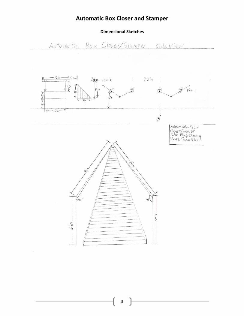
Dimensional Sketches 3
Side View 3
Flap Closer Poles 3
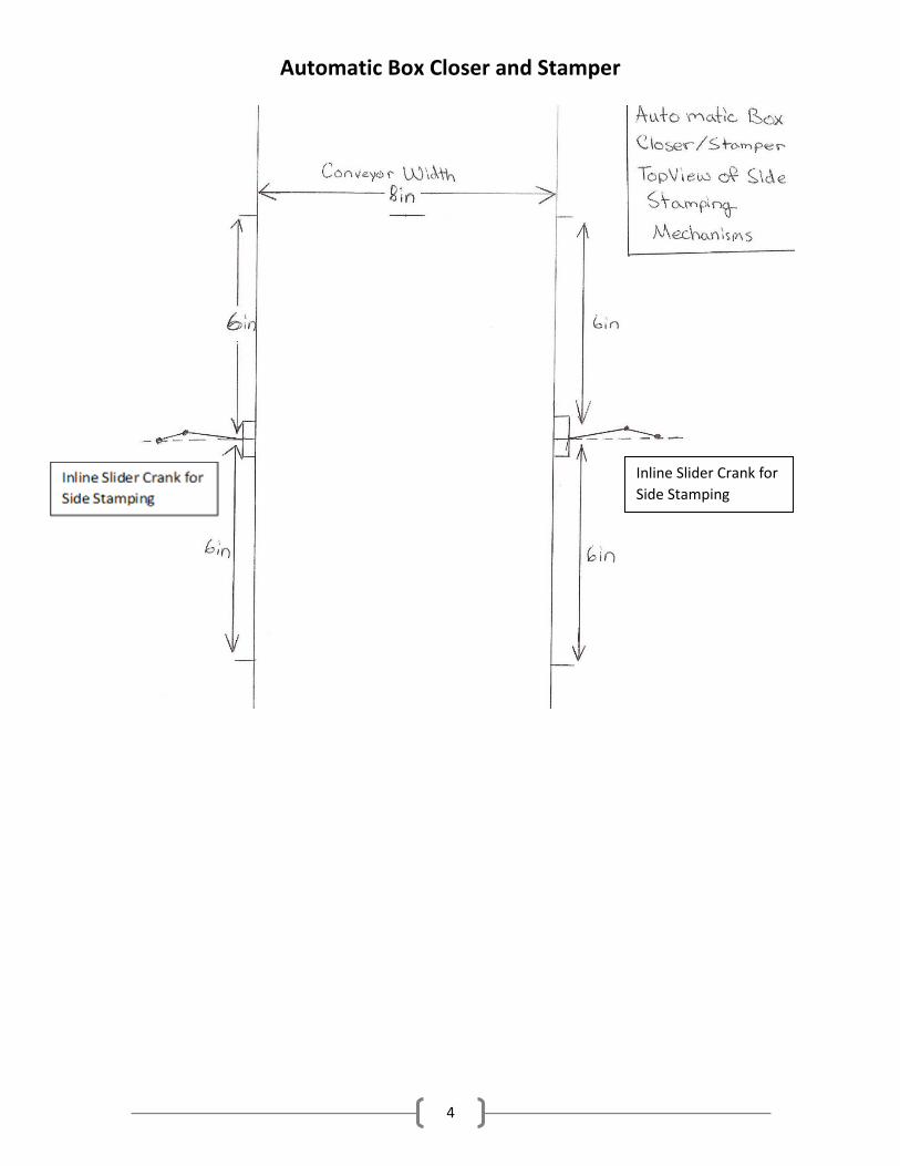
Top View of Side Stampers 4
Kinematic Diagrams 5
Offset Crank Slider 5
Crank Rocker 5 & 6
Inline Crank Slider 6
Calculations and Graphical Position Analysis 7
Inline Crank Slider 7
Offset Crank Slider 7
Crank Rocker 8
Displacement Vs. Time Diagrams 9
Flap Cams 9
Taping Cam 10
Crank Rocker 11
Offset Crank Slider 11
Diverter 12

Automatic Box Closer and Stamper
2
Mechanism Uses
The first step in the process is to stop the box with a slider-crank for 2 seconds. Then a
single camshaft with two cams located 12 inches apart to provide a drop of 4 inches in order to
close the initial flaps. The stroke will have a distance of 4 inches. The drive speed of the
camshaft will run at 30 rpm with a timing of 1.5 seconds to completely rise and fall. Once the
flaps are closed the box will continue down the rollers and pass through two bars located 4
inches from the end of the shaft at a 45° angle on each side to automatically fold the side flaps.
Afterwards the box moves on to the taping process.
The taping procedure happens in 0.67 seconds after the flaps are lowered. This happens
by the way of another cam which starts 2 inches below the top surface fully lifted to make
initial contact with the side of the box. The cam then rotates to the base circle and runs the
length of the box. Once to the end the cam then returns to the fully lifted position to finish
taping. This whole process consumes six seconds with rise and fall of each being one second.
The dwell to tape the length of the box is four seconds.
After the completion of the taping the box continues along until it is stopped by the
offset slider crank. The offset slider crank acts as a stopping mechanism performing a linear
motion from underneath the rollers to rise up hold the box for final stamping. The box stopper
will go through a stroke of 4.04 inches. This will hold the box over a period of 2 seconds while
the final stamping occurs which is how long it takes to complete a cycle.
Once stopped, the crank rockers located on the leading and trailing ends of the box
swing down to stamp the ends. At the same time a crank slider on each side of the box will
place the side stamps. Both stamping crank rockers are mounted ten inches above the
conveyor. The crank rockers operate with a throw of 98.3 degrees from fully retracted to the
fully extended stamping position. The crank rockers are both operating at 30 RPM speed the
crank rotates and then resets. The velocity of the stamping head is 25.1 in/sec. The rollers on
the line are running at a constant velocity of 3 in/sec with 10 sec between boxes. In order to
stamp the sides an inline slider crank is installed on each side of the conveyor. These are
centered at six inches horizontally from the stopper while being mounted at three inches in the
vertical position. The side stampers run at 30 rpm when triggered to operate. The stroke for
them is one inch total with a half inch each way.
At the end of our conveyor it will split into two directions separating the finished boxes
into two different lots. The diverter will be operated by a motor attached to an arm that swings
back and forth each time the stop plate makes a cycle. So each time the stopper from the
stamping process starts to rise the diverter motor switches sides and dwells at that position
until the next cycle begins.
Automatic Box Closer and Stamper
3
Dimensional Sketches
Automatic Box Closer and Stamper
4
Inline Slider Crank for
Side Stamping

Automatic Box Closer and Stamper
5
Kinematic Diagrams

Automatic Box Closer and Stamper
6

Automatic Box Closer and Stamper
7
Calculations and Graphical Position Analysis

Automatic Box Closer and Stamper
8

Automatic Box Closer and Stamper
9
Displacement Vs. Time Diagrams
Flap Cam Diagrams

Automatic Box Closer and Stamper
10
Taping Cam Diagram

Automatic Box Closer and Stamper
11

Automatic Box Closer and Stamper
12
Diverter