final presentation
TRANSCRIPT

Design and Fabrication of a Compact Multi-Design and Fabrication of a Compact Multi-Band Planar Inverted-F Antenna with Band Planar Inverted-F Antenna with
Reduced SARReduced SAR
Presented By :
Hrudya
M.Tec ECE

ObjectivesObjectives
The objectives of the work are as follows:
1
AbstractAbstract PIFA antenna structure is one of the most promising candidate in the
category of antennas used in handheld devices.
The proposed antenna is simulated with commercially available
software CST microwave studio.
The dimensions of the antenna is designed and optimized to meet the
required characteristics.
2

Planar Inverted-F Antenna Planar Inverted-F Antenna (PIFA)(PIFA)
3

PIFA from MonopolePIFA from Monopole
4

PIFA as a PIFA as a /4 Antennaλ/4 Antennaλ
5

Principle of operationPrinciple of operation
6
The patch acts approximately as a resonant cavity (short circuit
walls on top bottom and side, open-circuit walls on the other side).
If the antenna is excited at a resonant frequency, a strong field is set
up inside the cavity, and a strong current on the surface of the
patch.
The electric fields that extend out from the open circuit edge of
PIFA (called fringing felids ) causes PIFA to radiate.
This produces significant radiation.

Feeding techniqueFeeding technique
7
Basic Equation Basic Equation
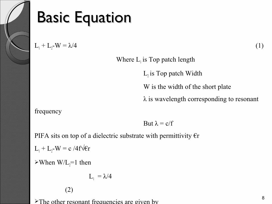
L1 + L2-W = λ/4 (1)
Where L1 is Top patch length
L2 is Top patch Width
W is the width of the short plate
λ is wavelength corresponding to resonant
frequency
But λ = c/f
PIFA sits on top of a dielectric substrate with permittivity €r
L1 + L2-W = c /4f√€r
When W/L2=1 then
L1 = λ/4
(2)
The other resonant frequencies are given by
L3+W3 = c /4f√€r
(3)
L4+W4 = c /4f√€r
(4)
8
Advantages
9
The Low weight and small volume.
Low fabrication cost.
Mechanically robust.
Capable of dual and triple frequency operations.
Geometry allows electronic peripherals to wedge in between the
spaces .

SAR and StandardsSAR and Standards SAR (Specific absorption rate) - Rate at which radiation is absorbed
by human body, measured in watts per kg (W/kg).
When the body is exposed to high frequency radiation, because of the absorption of energy heat is generated and is carried away by the thermo regulatory mechanism of body
In India, max. SAR limit for cell phones is 1.6W/Kg
It has a safety margin of 3 to 4
Quantity determined when the tests for the certification of electronic wireless equipment are performed.
10

SARSAR SAR represents the power (i.e. the energy rate) absorbed by the unitary
mass of substance (m).
Practical methods to determine SAR are suggested by
where
E represents the root mean square value of the electric field strength inside the body and
, and are the physical properties of the material , specific heat capacity, electric conductivity and mass density respectively 11
Software used to design the Software used to design the antennaantenna
12
CST MICROWAVE STUDIO is part of the
CST DESIGN STUDIO suite.
CST MICROWAVE STUDIO is a full-
featured software package for
electromagnetic analysis and design in the
high frequency range
It offers a number of different solvers for
different types of application

SIMULATIONS & SIMULATIONS & RESULTSRESULTS
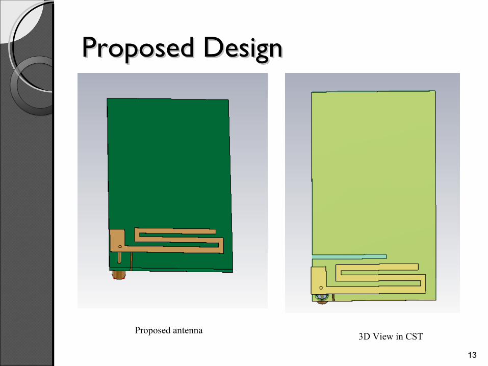
Proposed Design Proposed Design
3D View in CST
13
Proposed antenna

Detailed DimensionsDetailed Dimensions
14
Detailed Dimensions of top radiating patch
Detailed Dimensions of ground plane

Simulated Return Loss (S11)Simulated Return Loss (S11)
15

Simulated 3D Radiation Pattern – Simulated 3D Radiation Pattern – First BandFirst Band
16
Radiation pattern in the xyz plane Radiation pattern in the xy-z plane
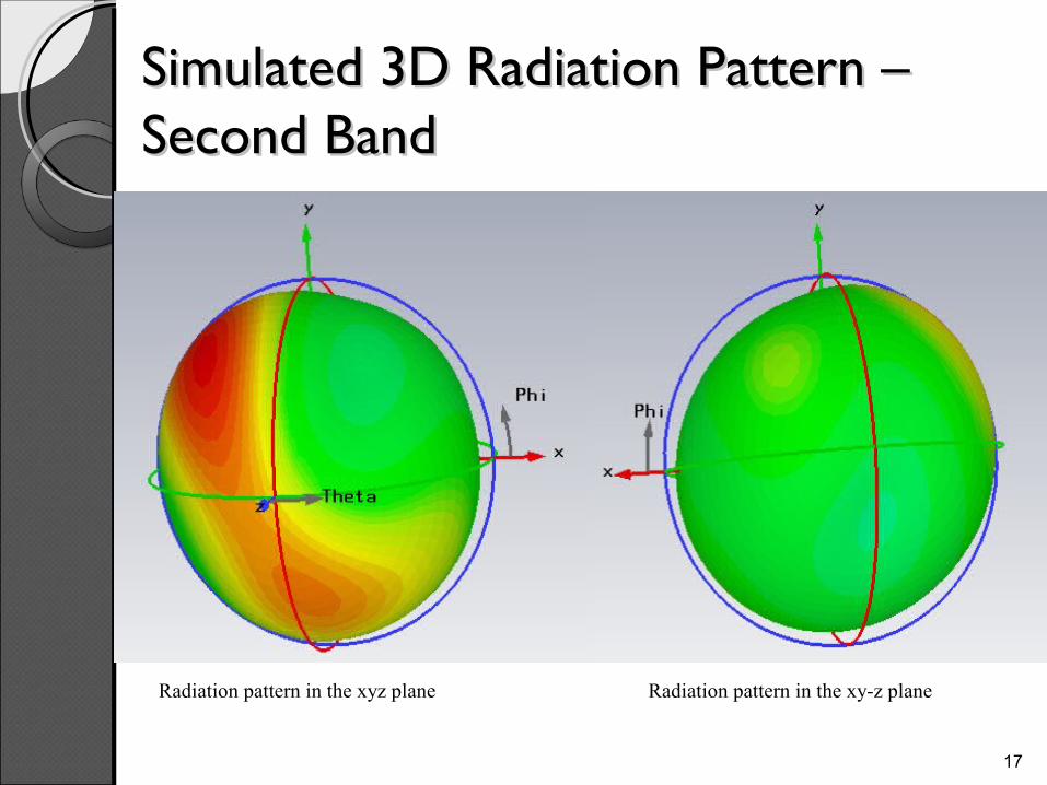
Simulated 3D Radiation Pattern – Simulated 3D Radiation Pattern – Second BandSecond Band
17
Radiation pattern in the xyz plane Radiation pattern in the xy-z plane

Simulated 3D Radiation Pattern – Simulated 3D Radiation Pattern – Third BandThird Band
18
Radiation pattern in the xyz planec Radiation pattern in the xy-z plane

SAR Testing in CST SAR Testing in CST
19
CST MWS version 2011 is used for modeling
and SAR analysis.
Standard Anthropomorphic Model (SAM)
head is a homogeneous model of the human
head composed of two parts: fluid and shell
SAM is filled with head tissue equivalent
materials and represents the average material
properties of the head.
The advantage of this model is that it
approximates real-life laboratory
measurements.
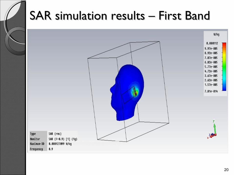
SAR simulation results – First BandSAR simulation results – First Band
20

SAR simulation results – First BandSAR simulation results – First Band
21

SAR simulation results – Second BandSAR simulation results – Second Band
22

SAR simulation results – Second BandSAR simulation results – Second Band
23
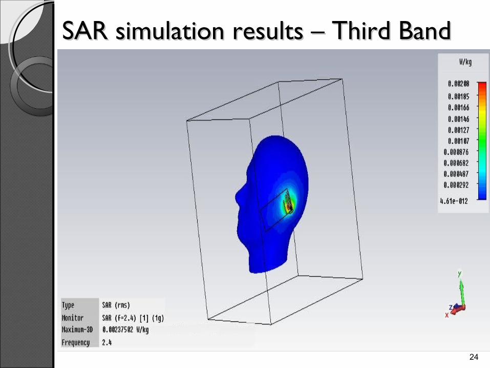
SAR simulation results – Third BandSAR simulation results – Third Band
24

SAR simulation results – Third BandSAR simulation results – Third Band
25

HARDWARE HARDWARE IMPLEMENTATION & IMPLEMENTATION &
RESULTSRESULTS

Fabricated AntennaFabricated Antenna
26
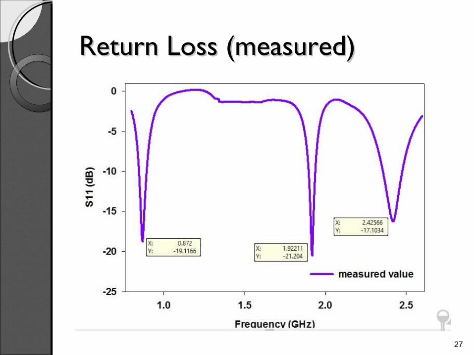
Return Loss (measured)Return Loss (measured)
27

Radiation Pattern (measured in xy Radiation Pattern (measured in xy plane)plane)
28
First Band
Second Band
Third Band

Radiation Pattern (measured in yz Radiation Pattern (measured in yz plane)plane)
29
First Band
Second Band
Third Band

CONCLUSIONCONCLUSION
Conclusion and Future Scope Conclusion and Future Scope
30
Few conclusions drawn from this work are:
Agreement between simulation results and measurement data is
good.
The designed multi-band antenna, built on PIFA structure, is very
sensitive to any changes to the dimensions of the structure including
the ground plane.
Only precise fabrication can yield the simulated results . Even small
changes in dimensions can affect the performance significantly.
Future Scope:
The design proposed here can be extended by adding more number
of bands .

ApplicationsApplications
31
The proposed antenna covers GSM 900 , GSM 1900, Bluetooth and
Wi-Fi band.
Can be used in mobile communication system.

ReferencesReferences[1] Kin-Lu Wong, “Planar Antennas for Wireless Communication”, Published John Wiley & Sons, Inc., Chapter: 2,
Page(s): 26-65, 2003.
[2] P. S. Hall, E. Lee, and C. T. P. Song, “Planar inverted-F antennas,” in Printed Antennas for Wireless Communications, R. Waterhouse, Ed. Hoboken, NJ: Wiley, 2007, ch. 7
[3] Naveen Kumar , Garima Saini ,A Novel Low profile Planar Inverted-F Antenna (PIFA) for Mobile Handsets,International Journal of Scientific and Research Publications, Volume 3, Issue 3, March 2013.
[4] Hang Wong, Kwai-Man Luk, Chi Hou Chan, QuanXue, Kwok Kan So, HauWah Lai, “Small antennas in Wireless Communications”, Proceedings of the IEEE Journal, July 2012.
[5] Ray J.A, Chaudhuri S.R.B., “A review of PIFA technology”, IEEE Indian Antenna week (IAW),Dec. 2011.
[6] Belhadef, Y.; BoukliHacene, N., “PIFAS antennas design for mobile communications”, 7th IEEE International Workshop on Systems, Signal Processing and their Applications (WOSSPA), May 2011.
[7] SinhyungJeon, Hyengcheul Choi, and Hyeongdong Kim, “Hybrid Planar Inverted-F Antenna with a T-shaped slot on the ground plane”, ETRI Journal, Vol. 31, October 2009.
[8] Krzysztofik, W.J.; Skikiewicz, A., “Tapered PIFA Antenna for Handsets Terminals”, 17th IEEE International Conference on Microwaves, Radar and Wireless Communications (MIKON), May 2008.
32
