final hardware report
TRANSCRIPT
1
DESIGN OF SOLAR POWERED WOOD CUTTER
HARDWARE PROJECT
(MEE218)
BACHELOR OF TECHNOLOGY
in
MECHANICAL ENGINEERING
by
PARTH TYAGI (13BME0156)
ASHUTOSH KHUSHU (13BME0177)
SIDDHANT SHRIVASTVA (13BME0296)
School of Mechanical Engineering

2
DECLARATION BY THE CANDIDATES
We, Parth Tyagi, Ashutosh Khushu and myself, Siddhant Shrivastava hereby
declare that the hardware project titled ‘Solar Wood Cutter’ made by us in
Vellore Institute of Technology, Vellore is a record of bonafide project work
carried out by us under the supervision of Prof. Bikash Routh. I also declare
that the work done in this project has not be submitted and will not be submitted
for the award of any other degree or diploma in this university or any other.
Place: Vellore
Date: 29/09/16

3
School of Mechanical Engineering
CERTIFICATE
This is to certify that the project report entitled Solar Wood Cutter” submitted
by Siddhant Shrivastava (13BME0296), Ashutosh Khushu (13BME0177) and
Parth Tyagi (13BME0156) to Vellore Institute of Technology University,
Vellore, in partial fulfilment of the requirement for the award of the degree of B
Tech in Mechanical Engineering is a record of bona fide work carried out by
them under my guidance. The project fulfils the requirements as per the
regulations of this Institute and in my opinion meets the necessary standards for
submission. The contents of this report have not been submitted and will not be
submitted either in part or in full, for the award of any other degree or diploma
and the same is certified.
Guide Examiner

4
ACKNOWLEDGEMENT
We would like to thank our Project guide Prof Bikash Routh and also our
project reviewer Dr. Balan A.S.S for the successful completion of this project.
Their constant help and guidance helped us overcome our adversities and
obstacles which we faced during our project. Their innovative solutions to our
problems helped us in places that we were stuck in and because of those
solutions we have our project complete and in running condition today.
Place: Vellore
Date: 29/09/16
5
TABLE OF CONTENTS
CHAPTER TOPIC PAGE NO.
1 Introduction and
Literature Survey
6
Solar Panel 7
Motor 7
Four bar Linkage 8
Studies 9
Objectives 9
2 Methodology 10
Bill of Materials 10
Material Selection 10
3 Results and Discussions 11
4 Conclusion and Scope
for Future Work
12
Reference 12

6
Chapter 1
Introduction
With the slowly but gradually diminishing natural non-renewable resources due to the
ever increasing demand of energy by the population of the world, it is of utmost
importance to develop new methods to harness the energy generation capabilities of
renewable energy sources. With sunlight being an infinite source of energy,
harnessing sunlight is definitely one of the most important methods to generate energy
in the near future. With solar panels being the primary way of harnessing the sun’s
energy, it is important to develop efficient solar panels which can create and sustain
enough energy to be used on a wide scale. This is the reason we chose this topic as
there is likely to be a wide demand for renewable sources of energy in the future.
The main components of our working model are:-
1. Solar panel - A solar panel is made up of several photovoltaic cells. These cells
convert sunlight to energy by the photovoltaic effect.
The photovoltaic effect is the creation of voltage or electric current in a material
upon exposure to sunlight. It is a physical and chemical phenomenon.
2. Circuit – Our circuit consists of a battery, a switch and a motor.
3. Motor – Our motor utilizes a crank and rocker mechanism for the linear motion of
the saw. When the crank rotates in the clockwise direction, it makes the saw
perform a linear motion. We made the crank as the shortest link.
4. Saw – Our saw utilizes the material high speed steel.
Solar Panel Battery Motor
K
e
y
Crank-
rocker
mechanis
m
7
Literature Survey
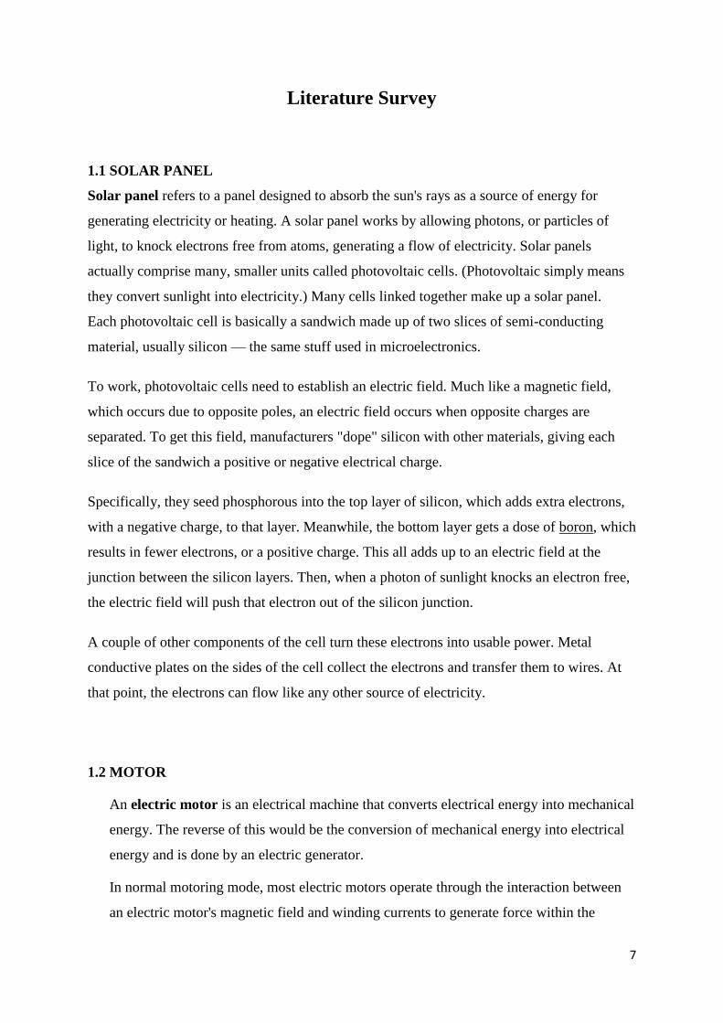
1.1 SOLAR PANEL
Solar panel refers to a panel designed to absorb the sun's rays as a source of energy for
generating electricity or heating. A solar panel works by allowing photons, or particles of
light, to knock electrons free from atoms, generating a flow of electricity. Solar panels
actually comprise many, smaller units called photovoltaic cells. (Photovoltaic simply means
they convert sunlight into electricity.) Many cells linked together make up a solar panel.
Each photovoltaic cell is basically a sandwich made up of two slices of semi-conducting
material, usually silicon — the same stuff used in microelectronics.
To work, photovoltaic cells need to establish an electric field. Much like a magnetic field,
which occurs due to opposite poles, an electric field occurs when opposite charges are
separated. To get this field, manufacturers "dope" silicon with other materials, giving each
slice of the sandwich a positive or negative electrical charge.
Specifically, they seed phosphorous into the top layer of silicon, which adds extra electrons,
with a negative charge, to that layer. Meanwhile, the bottom layer gets a dose of boron, which
results in fewer electrons, or a positive charge. This all adds up to an electric field at the
junction between the silicon layers. Then, when a photon of sunlight knocks an electron free,
the electric field will push that electron out of the silicon junction.
A couple of other components of the cell turn these electrons into usable power. Metal
conductive plates on the sides of the cell collect the electrons and transfer them to wires. At
that point, the electrons can flow like any other source of electricity.
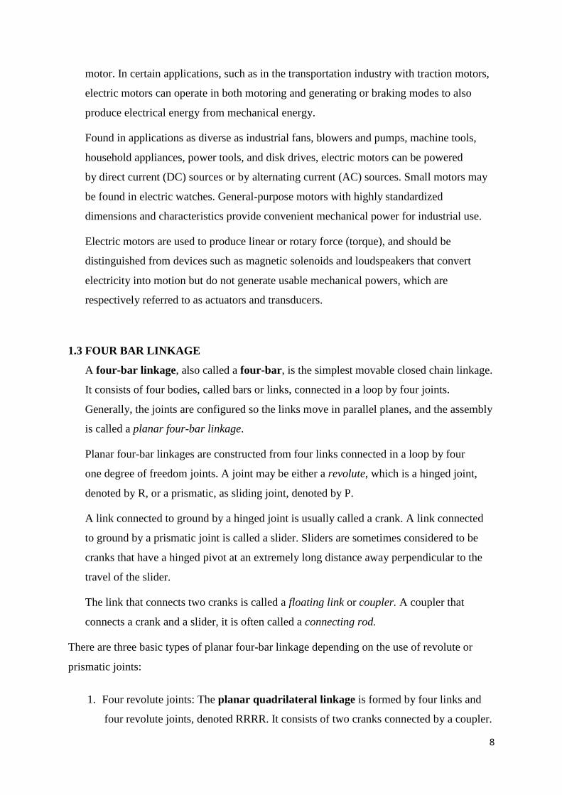
1.2 MOTOR
An electric motor is an electrical machine that converts electrical energy into mechanical
energy. The reverse of this would be the conversion of mechanical energy into electrical
energy and is done by an electric generator.
In normal motoring mode, most electric motors operate through the interaction between
an electric motor's magnetic field and winding currents to generate force within the
8
motor. In certain applications, such as in the transportation industry with traction motors,
electric motors can operate in both motoring and generating or braking modes to also
produce electrical energy from mechanical energy.
Found in applications as diverse as industrial fans, blowers and pumps, machine tools,
household appliances, power tools, and disk drives, electric motors can be powered
by direct current (DC) sources or by alternating current (AC) sources. Small motors may
be found in electric watches. General-purpose motors with highly standardized
dimensions and characteristics provide convenient mechanical power for industrial use.
Electric motors are used to produce linear or rotary force (torque), and should be
distinguished from devices such as magnetic solenoids and loudspeakers that convert
electricity into motion but do not generate usable mechanical powers, which are
respectively referred to as actuators and transducers.
1.3 FOUR BAR LINKAGE
A four-bar linkage, also called a four-bar, is the simplest movable closed chain linkage.
It consists of four bodies, called bars or links, connected in a loop by four joints.
Generally, the joints are configured so the links move in parallel planes, and the assembly
is called a planar four-bar linkage.
Planar four-bar linkages are constructed from four links connected in a loop by four
one degree of freedom joints. A joint may be either a revolute, which is a hinged joint,
denoted by R, or a prismatic, as sliding joint, denoted by P.
A link connected to ground by a hinged joint is usually called a crank. A link connected
to ground by a prismatic joint is called a slider. Sliders are sometimes considered to be
cranks that have a hinged pivot at an extremely long distance away perpendicular to the
travel of the slider.
The link that connects two cranks is called a floating link or coupler. A coupler that
connects a crank and a slider, it is often called a connecting rod.
There are three basic types of planar four-bar linkage depending on the use of revolute or
prismatic joints:
1. Four revolute joints: The planar quadrilateral linkage is formed by four links and
four revolute joints, denoted RRRR. It consists of two cranks connected by a coupler.

9
2. Three revolute joints and a prismatic joint: The slider-crank linkage is constructed
from four links connected by three revolute and one prismatic joint, or RRRP. It can
be constructed with crank and a slider connected by the connecting rod. Or it can be
constructed as a two cranks with the slider acting as the coupler, known as
an inverted slider-crank.
3. Two revolute joints and two prismatic joints: The double slider is a PRRP
linkage. This linkage is constructed by connecting two sliders with a coupler link. If
the directions of movement of the two sliders are perpendicular then the trajectories
of the points in the coupler are ellipses and the linkage is known as an elliptical
trammel, or the Trammel of Archimedes.
1.4 STUDIES
The following are the papers we surveyed and studied:-
• Fabrication Of Solar Wood And Metal Cutting Hacksaw
• Design And Development Of Metal/Wood Cutting Tool By Using Solar Energy by
Archan B. Patel, Sagar R. Amrelia and Keyur S. Denpiya
Based on these papers, we found out the following:-
1. They have used a rack and pinion mechanism to actuate the linear motion of the saw.
We have used a crank rocker mechanism for the same purpose.
2. They have used a 230 V battery to power the motor but in our model, the motor is
powered solely by the solar panel.
1.5 OBJECTIVES
• Designing a system which makes the Wood cutter based motor running through solar
energy.
• The mechanised wood-cutter design is according to the present market demand and to
fulfil criteria customer needs.
It should be designed to crest a product in the market so that it will more quality and
innovative.
10
Chapter 2
Methodology
2.1 BILL OF MATERIALS
DENSO 12 VOLT DC MOTOR
12V 3 Amp Rechargeable Battery
BIPICO Hacksaw Blade
IFI Tech Super Bright 3 W Solar Panel
On-off-on Switch
Cast Iron frame
2.2 MATERIAL SELECTION
PROPERTIES GREY CI NODULAR CI AUSTEMPERED
CI
YOUNG’S
MODULUS
1 3 2
YIELD STRENGTH 1 2 3
STRENGTH TO
WEIGHT RATIO
3 2 1
THERMAL
EXPANSION
3 3 1
TOTAL 8 10 7
The material chosen for the frame, using above comparison, is Nodular Cast Iron.
11
Chapter 3
Results and Discussions
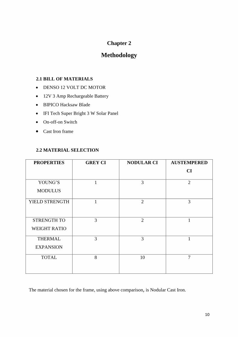
While working on this project we learnt the working of solar panel with charging setup. We
learnt the mechanism of usage of the panel. We were also successful in making the solar wood
cutter although its power output is slightly less which meant that we had to find batteries and
solar panels of higher capacity so that the rpm of the motor would have been high which would
have meant more power output and thus more efficiency. We also learnt about the crank rocker
mechanism and how it works.
3.1 BASIC LAYOUT
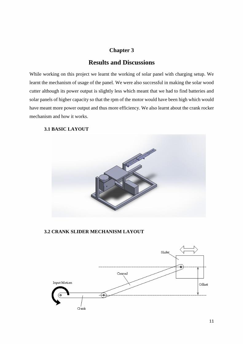
3.2 CRANK SLIDER MECHANISM LAYOUT

12
Chapter 4
Conclusion and Scope for Future Work
The solar wood cutter was made and the components are assembled and the working prototype
is found to be operational. It is designed to cut small pieces of wood. The following changes
can be made to improve the design and efficiency of the apparatus:-
• The length of the hacksaw can be made smaller. This will also result in a more rigid
setup as the holders on the two ends will be closer to one another.
• Decreasing the length of the connecting rod will help in increasing the speed of the
operation.
• Making an apparatus which can make the solar panel swivel in either direction will
solve the issue of lower energy generation when the sun is not exactly at the top of the
panel.
4.1 REFERENCE
• http://www.madehow.com/Volume-3/Saw.html
• http://encyclobeamia.solarbotics.net/articles/photovoltaic.html
• http://www.ecomall.com/greenshopping/solarpanels.htm
• www.makeitfrom.com
• Wikipedia and Google