final draft etsi en 302 686 v1.1 · transport systems (its). its communications may comprise...
TRANSCRIPT

Final draft ETSI EN 302 686 V1.1.0 (2010-12)
Harmonized European Standard (Telecommunications series)
Intelligent Transport Systems (ITS);Radiocommunications equipment operating
in the 63 GHz to 64 GHz frequency band;Harmonized EN covering the essential requirements
of article 3.2 of the R&TTE Directive

ETSI
Final draft ETSI EN 302 686 V1.1.0 (2010-12)2
Reference DEN/ERM-TG37-008
Keywords ITS, radio, regulation, testing
ETSI
650 Route des Lucioles F-06921 Sophia Antipolis Cedex - FRANCE
Tel.: +33 4 92 94 42 00 Fax: +33 4 93 65 47 16
Siret N° 348 623 562 00017 - NAF 742 C
Association à but non lucratif enregistrée à la Sous-Préfecture de Grasse (06) N° 7803/88
Important notice
Individual copies of the present document can be downloaded from: http://www.etsi.org
The present document may be made available in more than one electronic version or in print. In any case of existing or perceived difference in contents between such versions, the reference version is the Portable Document Format (PDF).
In case of dispute, the reference shall be the printing on ETSI printers of the PDF version kept on a specific network drive within ETSI Secretariat.
Users of the present document should be aware that the document may be subject to revision or change of status. Information on the current status of this and other ETSI documents is available at
http://portal.etsi.org/tb/status/status.asp
If you find errors in the present document, please send your comment to one of the following services: http://portal.etsi.org/chaircor/ETSI_support.asp
Copyright Notification
No part may be reproduced except as authorized by written permission. The copyright and the foregoing restriction extend to reproduction in all media.
© European Telecommunications Standards Institute 2010.
All rights reserved.
DECTTM, PLUGTESTSTM, UMTSTM, TIPHONTM, the TIPHON logo and the ETSI logo are Trade Marks of ETSI registered for the benefit of its Members.
3GPPTM is a Trade Mark of ETSI registered for the benefit of its Members and of the 3GPP Organizational Partners. LTE™ is a Trade Mark of ETSI currently being registered
for the benefit of its Members and of the 3GPP Organizational Partners. GSM® and the GSM logo are Trade Marks registered and owned by the GSM Association.

ETSI
Final draft ETSI EN 302 686 V1.1.0 (2010-12)3
Contents
Intellectual Property Rights ................................................................................................................................ 5
Foreword ............................................................................................................................................................. 5
Introduction ........................................................................................................................................................ 5
1 Scope ........................................................................................................................................................ 6
2 References ................................................................................................................................................ 7
2.1 Normative references ......................................................................................................................................... 7
2.2 Informative references ........................................................................................................................................ 7
3 Definitions, symbols and abbreviations ................................................................................................... 8
3.1 Definitions .......................................................................................................................................................... 8
3.2 Symbols .............................................................................................................................................................. 8
3.3 Abbreviations ..................................................................................................................................................... 9
4 Technical requirements specifications ..................................................................................................... 9
4.1 General requirements ......................................................................................................................................... 9
4.1.1 Receiver category ......................................................................................................................................... 9
4.2 Presentation of equipment for testing purposes .................................................................................................. 9
4.2.1 Choice of model for testing ........................................................................................................................ 10
4.2.2 Testing of equipment with alternative power levels ................................................................................... 10
4.3 Mechanical and electrical design ...................................................................................................................... 10
4.3.1 General ........................................................................................................................................................ 10
4.3.2 Controls ...................................................................................................................................................... 10
4.3.3 Transmitter shut-off facility ........................................................................................................................ 10
4.3.4 Receiver automatic switch-off .................................................................................................................... 10
4.3.5 Marking (equipment identification) ............................................................................................................ 10
4.3.5.1 Equipment identification ....................................................................................................................... 10
4.3.5.2 Marking ................................................................................................................................................. 11
4.4 Auxiliary test equipment .................................................................................................................................. 11
4.5 General requirements for RF cables ................................................................................................................. 11
4.6 RF waveguides ................................................................................................................................................. 12
4.6.1 Wave Guide Attenuators ............................................................................................................................. 12
4.7 External harmonic mixers ................................................................................................................................ 12
4.7.1 Introduction................................................................................................................................................. 12
4.7.2 Signal identification .................................................................................................................................... 13
4.7.3 Measurement hints ...................................................................................................................................... 14
4.8 Interpretation of the measurement results ........................................................................................................ 14
4.8.1 Conversion loss data and measurement uncertainty ................................................................................... 15
5 Test conditions, power sources and ambient temperatures .................................................................... 16
5.1 Normal and extreme test conditions ................................................................................................................. 16
5.2 Test power source ............................................................................................................................................. 16
5.2.1 External test power source .......................................................................................................................... 16
5.2.2 Internal test power source ........................................................................................................................... 17
5.3 Normal test conditions ...................................................................................................................................... 17
5.3.1 Normal temperature and humidity .............................................................................................................. 17
5.3.2 Normal test power source ........................................................................................................................... 17
5.3.2.1 Mains voltage ........................................................................................................................................ 17
5.3.2.2 Other power sources .............................................................................................................................. 17
5.4 Extreme test conditions .................................................................................................................................... 17
5.4.1 Extreme temperatures ................................................................................................................................. 17
5.4.2 Extreme test source voltages ....................................................................................................................... 17
5.4.2.1 Mains voltage ........................................................................................................................................ 17
5.4.2.2 Regulated lead-acid battery power sources ........................................................................................... 17
5.4.2.3 Power sources using other types of batteries ......................................................................................... 18
5.4.2.4 Other power sources .............................................................................................................................. 18

ETSI
Final draft ETSI EN 302 686 V1.1.0 (2010-12)4
6 General conditions .................................................................................................................................. 18
6.1 Normal test signals and test modulation ........................................................................................................... 18
6.1.1 Normal test signals for data ........................................................................................................................ 19
6.1.2 Product Information .................................................................................................................................... 19
6.1.3 Testing of frequency agile or hopping equipment ...................................................................................... 19
6.2 Test sites and general arrangements for radiated measurements ...................................................................... 19
6.2.1 Test fixture .................................................................................................................................................. 19
6.2.1.1 Requirements ........................................................................................................................................ 19
6.2.1.2 Calibration ............................................................................................................................................. 20
6.2.1.3 Test Sites and general arrangement ....................................................................................................... 21
6.2.1.3.1 Open Area Test Site (OATS) ........................................................................................................... 21
6.2.1.3.2 Other test sites ................................................................................................................................. 22
6.2.1.3.3 Semi-Anechoic Rooms with a conductive Ground Plane ................................................................ 22
6.2.1.3.4 Fully Anechoic Rooms (FAR) ......................................................................................................... 23
6.2.1.3.5 Minimum requirements for test sites for measurements above 18 GHz .......................................... 25
6.3 Measuring receiver ........................................................................................................................................... 26
6.4 Antennas ........................................................................................................................................................... 27
6.4.1 Test antenna ................................................................................................................................................ 27
6.4.2 Substitution antenna .................................................................................................................................... 27
6.4.3 Signalling antenna ...................................................................................................................................... 28
7 Methods of measurement and limits for transmitter parameters ............................................................ 28
7.1 RF output power (mean e.i.r.p.) ....................................................................................................................... 28
7.1.1 Definition .................................................................................................................................................... 28
7.1.2 Limit ........................................................................................................................................................... 28
7.1.3 Conformance............................................................................................................................................... 29
7.2 Permitted range of operating frequencies ......................................................................................................... 29
7.2.1 Definition .................................................................................................................................................... 29
7.2.2 Method of measurement ............................................................................................................................. 29
7.2.3 Method of measurement for equipment using FHSS modulation ............................................................... 30
7.2.4 Limit ........................................................................................................................................................... 30
7.3 Unwanted emissions in the spurious domain.................................................................................................... 31
7.3.1 Definition .................................................................................................................................................... 31
7.3.2 Method of measurement - radiated unwanted emissions ............................................................................ 31
7.3.3 Limits .......................................................................................................................................................... 32
8 Receiver .................................................................................................................................................. 32
8.1 Unwanted emissions ......................................................................................................................................... 32
8.1.1 Definition .................................................................................................................................................... 32
8.1.2 Method of measurement radiated unwanted components ........................................................................... 33
8.1.3 Limits .......................................................................................................................................................... 33
Annex A (normative): HS Requirements and conformance Test specifications Table (HS-RTT) ................................................................................................................ 34
Annex B (normative): Radiated measurements ................................................................................ 36
B.1 Substitution method ................................................................................................................................ 36
B.1.1 Principle of the substitution measurement method ........................................................................................... 36
B.2 Pre-Substitution method ......................................................................................................................... 37
B.2.1 Principle of radiated power measurement based on site attenuation (Pre-Substitution) ................................... 37
Annex C (informative): Atmospheric absorptions and material dependent attenuations ............... 39
C.1 Atmospheric absorptions ........................................................................................................................ 39
C.2 Material dependent attenuations ............................................................................................................. 41
Annex D (informative): The EN title in the official languages ........................................................... 43
History .............................................................................................................................................................. 44

ETSI
Final draft ETSI EN 302 686 V1.1.0 (2010-12)5
Intellectual Property Rights IPRs essential or potentially essential to the present document may have been declared to ETSI. The information pertaining to these essential IPRs, if any, is publicly available for ETSI members and non-members, and can be found in ETSI SR 000 314: "Intellectual Property Rights (IPRs); Essential, or potentially Essential, IPRs notified to ETSI in respect of ETSI standards", which is available from the ETSI Secretariat. Latest updates are available on the ETSI Web server (http://webapp.etsi.org/IPR/home.asp).
Pursuant to the ETSI IPR Policy, no investigation, including IPR searches, has been carried out by ETSI. No guarantee can be given as to the existence of other IPRs not referenced in ETSI SR 000 314 (or the updates on the ETSI Web server) which are, or may be, or may become, essential to the present document.
Foreword This Harmonized European Standard (Telecommunications series) has been produced by ETSI Technical Committee Electromagnetic compatibility and Radio spectrum Matters (ERM), and is now submitted for the Vote phase of the ETSI standards Two-step Approval Procedure.
For non-EU countries, the present document may be used for regulatory (Type Approval) purposes.
The present document has been produced by ETSI in response to a mandate from the European Commission issued under Council Directive 98/34/EC (as amended) [i.4] laying down a procedure for the provision of information in the field of technical standards and regulations.
The present document is intended to become a Harmonized Standard, the reference of which will be published in the Official Journal of the European Communities referencing the Directive 1999/5/EC [i.9] of the European Parliament and of the Council of 9 March 1999 on radio equipment and telecommunications terminal equipment and the mutual recognition of their conformity ("the R&TTE Directive").
The requirements relevant to Directive 1999/5/EC [i.9] are summarised in annex A.
Equipment compliant with the present document can be intended for fitment into road vehicles, therefore it is subject to automotive EMC type approval and Directive 95/54/EC [i.7]. For use on vehicles outside the scope of Directive 95/54/EC [i.7], compliance with an EMC directive/standard appropriate for that use is required.
Proposed national transposition dates
Date of latest announcement of this EN (doa): 3 months after ETSI publication
Date of latest publication of new National Standard or endorsement of this EN (dop/e):
6 months after doa
Date of withdrawal of any conflicting National Standard (dow): 18 months after doa
Introduction The present document is part of a set of standards developed by ETSI and is designed to fit in a modular structure to cover all radio and telecommunications terminal equipment within the scope of the R&TTE Directive. The modular structure is shown in EG 201 399 [i.8].

ETSI
Final draft ETSI EN 302 686 V1.1.0 (2010-12)6
1 Scope The present document applies to corporate communications using radio transmitters and receivers for Intelligent Transport Systems (ITS). ITS communications may comprise vehicle-to-vehicle, vehicle-to-infrastructure and infrastructure-to-vehicle.
The equipment is comprised of a transmitter and associated encoder and modulator and/or a receiver and associated demodulator and decoder. The types of equipment covered by the present document are as follows:
• OnBoard Equipment (OBE equipment fitted with an integral or dedicated antenna(s), intended for use in vehicles, e.g. a road or a rail vehicle).
• Road Side Equipment (RSE equipment fitted with an antenna socket, integral or dedicated antenna(s), normally used as a fixed station); e.g. a road or rail infrastructure.
These networks operate over a short range with very wideband communications using a variety of directional medium and high gain antennas to enable a high degree of spectrum reuse, and may use a flexible bandwidth scheme under which they normally operate in a wideband mode, and periodically reduce their bandwidth (e.g. for antenna training and other activities).
The technical characteristics of these applications are described in TR 102 400 [i.1], where ITS applications in the 63 GHz to 64 GHz band is described. The present document is also in line with the results of the of the spectrum compatibility study in the CEPT ECC Report 113 [i.3].
These radio equipment types are capable of operating in all or any part of the frequency bands given in table 1.
Table 1: Radiocommunications service frequency bands
Radiocommunications service frequency bands Transmit 63 GHz to 64 GHz Receive 63 GHz to 64 GHz
The present document is intended to cover the provisions of Directive 1999/5/EC [i.9] (R&TTE Directive), article 3.2, which states that "….. radio equipment shall be so constructed that it effectively uses the spectrum allocated to terrestrial/space radio communications and orbital resources so as to avoid harmful interference".
In addition to the present document, other ENs that specify technical requirements in respect of essential requirements under other parts of article 3 of the R&TTE Directive may apply to equipment within the scope of the present document.
NOTE: A list of such ENs is included on the web site http://www.newapproach.org.

ETSI
Final draft ETSI EN 302 686 V1.1.0 (2010-12)7
2 References References are either specific (identified by date of publication and/or edition number or version number) or non-specific. For specific references, only the cited version applies. For non-specific references, the latest version of the reference document (including any amendments) applies.
Referenced documents which are not found to be publicly available in the expected location might be found at http://docbox.etsi.org/Reference.
NOTE: While any hyperlinks included in this clause were valid at the time of publication ETSI cannot guarantee their long term validity.
2.1 Normative references The following referenced documents are necessary for the application of the present document.
[1] ETSI TR 100 028 (all parts) (V1.4.1): "Electromagnetic compatibility and Radio spectrum matters (ERM); Uncertainties in the measurement of mobile radio equipment characteristics".
[2] CISPR 16 (2006) (parts 1-1, 1-4 and 1-5): "Specification for radio disturbance and immunity measuring apparatus and methods; Part 1: Radio disturbance and immunity measuring apparatus".
[3] ITU-T Recommendation O.153 (1992): "Basic parameters for the measurement of error performance at bit rates below the primary rate".
[4] ETSI TR 102 273 (all parts) (V1.2.1): "Electromagnetic compatibility and Radio spectrum Matters (ERM); Improvement on Radiated Methods of Measurement (using test site) and evaluation of the corresponding measurement uncertainties".
2.2 Informative references The following referenced documents are not necessary for the application of the present document but they assist the user with regard to a particular subject area.
[i.1] ETSI TR 102 400 (V1.2.1): "Electromagnetic compatibility and Radio spectrum Matters (ERM); Short Range Devices (SRD); Intelligent Transport Systems (ITS); Road Traffic and Transport Telematics (RTTT); Technical characteristics for communications equipment in the frequency band from 63 GHz to 64 GHz; System Reference Document".
[i.2] ETSI TS 103 051: "Electromagnetic compatibility and Radio spectrum Matters (ERM); Expanded measurement uncertainty for the measurement of radiated electromagnetic fields".
[i.3] CEPT ECC Report 113: "Compatibility studies around 63 GHz between Intelligent Transportation Systems (ITS) and other systems".
[i.4] Directive 98/34/EC of the European Parliament and of the Council of 22 June 1998 laying down a procedure for the provision of information in the field of technical standards and regulations.
[i.5] ETSI TS 103 052: "Electromagnetic compatibility and Radio spectrum Matters (ERM); Radiated measurement methods and general arrangements for test sites up to 100 GHz".
[i.6] CEPT/ERC Recommendation 74-01 (2005): "Unwanted emissions in the spurious domain".
[i.7] Commission Directive 95/54/EC of 31 October 1995 adapting to technical progress Council Directive 72/245/EEC on the approximation of the laws of the Member States relating to the suppression of radio interference produced by spark-ignition engines fitted to motor vehicles and amending Directive 70/156/EEC on the approximation of the laws of the Member States relating to the type-approval of motor vehicles and their trailers.
[i.8] ETSI EG 201 399: "Electromagnetic compatibility and Radio spectrum Matters (ERM); A guide to the production of Harmonized Standards for application under the R&TTE Directive".

ETSI
Final draft ETSI EN 302 686 V1.1.0 (2010-12)8
[i.9] Directive 1999/5/EC of the European Parliament and of the Council of 9 March 1999 on radio equipment and telecommunications terminal equipment and the mutual recognition of their conformity (R&TTE Directive).
[i.10] ITU-R Recommendation P.676-5 (2001): "Attenuation by atmospheric gases".
3 Definitions, symbols and abbreviations
3.1 Definitions For the purposes of the present document, the terms and definitions given in the R&TTE Directive [i.9] and the following apply:
channel separation: minimum separation (in MHz) between the centre frequencies of two adjacent channels in the channel plan of the radio equipment
environmental profile: declared range of environmental conditions under which equipment within the scope of the present document is required to be compliant
integral antenna: antenna which is declared to be part of the radio equipment by the supplier
NOTE 1: In some cases, it may not be possible to remove an integral antenna or expose an antenna connector without changing the output characteristics of the radio equipment.
NOTE 2: Even with an integral antenna, it might still be possible to separate the antenna from the equipment using a special tool.
mean power: when applied to a modulated signal, this is the power (transmitted or received) in a bandwidth
necessary bandwidth: width of the frequency band which is just sufficient to ensure the transmission of information at the rate and with the quality required under specified conditions
smart antenna systems: equipment that combines multiple transmit and/or receive antenna elements with a signal processing function to increase its radiation and/or reception capabilities
NOTE: This includes techniques such as spatial multiplexing, beam forming, cyclic delay diversity, etc.
3.2 Symbols For the purposes of the present document, the following symbols apply:
dBc spectral density relative to the maximum spectral power density of the transmitted signal dBm decibel relative to one milliwatt dBr decibel relative to a given maximum power level GHz thousand millions of cycles kHz thousands of cycles μs millionths of seconds

ETSI
Final draft ETSI EN 302 686 V1.1.0 (2010-12)9
3.3 Abbreviations For the purposes of the present document, the following abbreviations apply:
e.i.r.p. equivalent isotropically radiated power emf electromotive force EUT Equipment Under Testing FAR Fully Anechoic Room FH Frequency Hopping FHSS Frequency Hopping Spread Spectrum FMCW Frequency Modulated Carrier Wave FSK Frequency Shift Keying FSL Free Space Loss IF Intermediate Frequency LO Local Oscillator NSA Normalized Site Attenuatio OATS Open Area Test Site PDL spectral Power Density Limit R&TTE Radio equipment and Telecommunications Terminal Equipment RBw Resolution Bandwidth RF Radio Frequency RMS Root Mean Square Rx Receiver Tx Transmitter VBW Video Bandwidth VSWR Voltage Standing Wave Ratio
4 Technical requirements specifications
4.1 General requirements
4.1.1 Receiver category
For ITS equipment in the scope of the present document, there is no need to distinguish between different receiver categories.
4.2 Presentation of equipment for testing purposes Equipment submitted for testing, where applicable, shall fulfil the requirements of the present document on all frequencies over which it is intended to operate.
Where appropriate, testing shall be carried out on suitable frequencies for the equipment concerned.
If equipment is designed to operate with different carrier powers, measurements of each transmitter parameter shall be performed at the highest power level at which the transmitter is intended to operate.
Additionally, technical documentation and operating manuals, sufficient to allow testing to be performed, shall be available.
A test fixture for equipment with an integral antenna may be supplied (see clause 6.2.1).
To simplify and harmonize the testing procedures between the different testing laboratories, measurements shall be performed, according to the present document, on samples of equipment defined in clause 4.2.1.
These clauses are intended to give confidence that the requirements set out in the present document have been met without the necessity of performing measurements on all frequencies.

ETSI
Final draft ETSI EN 302 686 V1.1.0 (2010-12)10
The provider shall declare the frequency range(s), the range of operation conditions and power requirements, as applicable, in order to establish the appropriate test conditions.
4.2.1 Choice of model for testing
One or more samples of the equipment, as appropriate, shall be tested.
Stand alone equipment shall be tested complete with any ancillary equipment needed for testing.
If equipment has several optional features, considered not to affect the RF parameters then the tests need only to be performed on the equipment configured with that combination of features considered to be the most complex.
4.2.2 Testing of equipment with alternative power levels
If a family of equipment has alternative output power levels provided by the use of separate power modules or add on stages, or additionally has alternative frequency coverage, then all these shall be declared. Each module or add on stage shall be tested in combination with the equipment. The necessary samples and tests shall be based on the requirements of clause 4. As a minimum, measurements of the radiated power (e.i.r.p.) and unwanted emissions shall be performed for each combination and shall be stated in the test report.
4.3 Mechanical and electrical design
4.3.1 General
The equipment tested shall be designed, constructed and manufactured in accordance with good engineering practice and with the aim of minimizing harmful interference to other equipment and services.
Transmitters and receivers may be individual or combination units.
4.3.2 Controls
Those controls which, if maladjusted, might increase the interfering potentialities of the equipment shall not be easily accessible to the user.
4.3.3 Transmitter shut-off facility
If the transmitter is equipped with an automatic transmitter shut-off facility, it should be made inoperative for the duration of the test. In the case this not possible, a proper test method shall be described and documented.
4.3.4 Receiver automatic switch-off
If the receiver is equipped with a battery-saving circuit for automatic switch-off, this circuit shall be made inoperative for the duration of the tests. In the case this not possible, a proper test method shall be described and documented.
4.3.5 Marking (equipment identification)
4.3.5.1 Equipment identification
The marking shall include as a minimum:
• the name of the manufacturer or his trademark;
• the type designation.

ETSI
Final draft ETSI EN 302 686 V1.1.0 (2010-12)11
4.3.5.2 Marking
The equipment shall be marked in a visible place. This marking shall be legible and durable. In cases where the equipment is too small to carry the marking, it is sufficient to provide the relevant information in the users' manual.
4.4 Auxiliary test equipment All necessary test signal sources and set-up information shall accompany the equipment when it is submitted for testing.
The following product information shall be provided by the manufacturer:
• the type of modulation technology implemented in the equipment (e.g. FMCW or pulsed);
• the operating frequency range(s) of the equipment;
• the intended combination of the transmitter/transceiver and its antenna and their corresponding e.i.r.p. levels in the main beam;
• the nominal power supply voltages of the radio equipment;
• for FMCW, FH, FSK or similar carrier based modulation schemes, it is important to describe the modulation parameters in order to ensure that the right settings of the measuring receiver are used. Important parameters are the modulation period, deviation or dwell times within a modulation period, rate of modulation (Hz/s);
• the implementation of features such as gating, hopping or stepped frequency hopping;
• the implementation of any mitigation techniques such as duty cycle;
• for pulsed equipment, the Pulse Repetition Frequency PRF shall be stated.
4.5 General requirements for RF cables All RF cables including their connectors at both ends used within the measurement arrangements and set-ups shall be of coaxial or waveguide type featuring within the frequency range they are used:
• a VSWR of less than 1,2 at either end;
• a shielding loss in excess of 60 dB.
When using coaxial cables for frequencies above 40 GHz attenuation features increase significantly and decrease of return loss due to mismatching caused by joints at RF connectors and impedance errors shall be considered.
All RF cables and waveguide interconnects shall be routed suitably in order to reduce impacts on antenna radiation pattern, antenna gain, antenna impedance. Table 2 provides some information about connector systems that can be used in connection with the cables.
Table 2: Connector systems
Connector System Frequency Recommended coupling torque N 18 GHz 0,68 Nm to 1,13 Nm
SMA 18 GHz (some up to 26 GHz)
~ 0,56 Nm
3,50 mm 26,5 GHz 0,8 Nm to 1,1 Nm 2,92 mm 40 GHz
(some up to 46 GHz) 0,8 Nm to 1,1 Nm
2,40 mm 50 GHz (some up to 60 GHz)
0,8 Nm to 1,1 Nm
1,85 mm 65 GHz (some up to 75 GHz)
0,8 Nm to1,1 Nm

ETSI
Final draft ETSI EN 302 686 V1.1.0 (2010-12)12
4.6 RF waveguides Wired signal transmission in the millimeter range is preferably realized by means of waveguides because they offer low attenuation and high reproducibility. Unlike coaxial cables, the frequency range in which waveguides can be used is limited also towards lower frequencies (highpass filter characteristics). Wave propagation in the waveguide is not possible below a certain cutoff frequency where attenuation of the waveguide is very high. Beyond a certain upper frequency limit, several wave propagation modes are possible so that the behaviour of the waveguide is no longer unambiguous. In the unambiguous range of a rectangular waveguide, only H10 waves are capable of propagation.
The dimensions of rectangular and circular waveguides are defined by international standards such as 153-IEC for various frequency ranges. These frequency ranges are also referred to as waveguide bands. They are designated using different capital letters depending on the standard. Table 3 provides an overview of the different waveguide bands together with the designations of the associated waveguides and flanges.
For rectangular waveguides, which are mostly used in measurements, harmonic mixers with matching flanges are available for extending the frequency coverage of measuring receivers. Table 3 provides some information on waveguides.
Table 3: Waveguide bands and associated waveguides
Band Frequency in GHz
Designations Internal dimensions of
waveguide
Designations of frequently used flanges
MIL-W-85 EIA 153-
IEC RCSC
(British) in mm in inches
MIL-F-3922
UG-XXX/U equivalent (reference)
Remarks
Ka 26,5 to 40,0 3-006 WR-28 R320 WG-22 7,11 x 3,56
0,280 x 0,140
54-006 68-002
67B-005
UG-559/U
UG-381/U
Rectangular Rectangular
Round Q 33,0 to 55,0 3-010 WR-22 R400 WG-23 5,69 x
2,84 0,224 x 0,112 67B-006 UG-383/U Round
U 40,0 to 60,0 3-014 WR-19 R500 WG-24 4,78 x 2,388
0,188 x 0,094 67B-007 UG-383/U-M Round
V 50,0 to 75,0 3-017 WR-15 R620 WG-25 3,759 x 1,879
0,148 x 0,074 67B-008 UG-385/U Round
E 60,0 to 90,0 3-020 WR-12 R740 WG-26 3,099 x 1,549
0,122 x 0,061 67B-009 UG-387/U Round
W 75,0 to 110,0
3-023 WR-10 R900 WG-27 2,540 x 1,270
0,100 x 0,050 67B-010 UG-383/U-M Round
As waveguides are rigid, it is unpractical to set up connections between antenna and measuring receiver with waveguides. Either a waveguide transition to coaxial cable is used or - at higher frequencies - the harmonic mixer is used for frequency extension of the measuring receiver and is directly mounted at the antenna.
4.6.1 Wave Guide Attenuators
Due to the fact that external harmonic mixers can only be fed with low RF power it may be necessary to attenuate input powers in defined manner using wave guide attenuators. These attenuators shall be calibrated and suitable to handle corresponding powers.
4.7 External harmonic mixers
4.7.1 Introduction
Measuring receivers (test receivers or spectrum analyzers) with coaxial input are commercially available up to 67 GHz. The frequency range is extended from 40 GHz to 67 GHz up to 100 GHz and beyond by means of external harmonic mixers. Harmonic mixers are used because the fundamental mixing commonly employed in the lower frequency range is too complex and expensive or requires components such as preselectors which are not available. Harmonic mixers are waveguide based and have a frequency range matching the waveguide bands. They must not be used outside these bands for calibrated measurements.

ETSI
Final draft ETSI EN 302 686 V1.1.0 (2010-12)13
In harmonic mixers, a harmonic of the local oscillator (LO) is used for signal conversion to a lower intermediate frequency (IF). The advantage of this method is that the frequency range of the local oscillator may be much lower than with fundamental mixing, where the LO frequency must be of the same order (with low IF) or much higher (with high IF) than the input signal (RF).The harmonics are generated in the mixer because of its nonlinearity and are used for conversion. The signal converted to the IF is coupled out of the line which is also used for feeding the LO signal.
To obtain low conversion loss of the external mixer, the order of the harmonic used for converting the input signal should be as low as possible. For this, the frequency range of the local oscillator must be as high as possible. LO frequency ranges are for example 3 GHz to 6 GHz or 7 GHz to 15 GHz. IF frequencies are in the range from 320 MHz to about 700 MHz. If the measured air interface is wider than the IF bandwidth, then it is advisable to split the measurement in several frequency ranges, i.e. a one step total RF output power measurement should not be performed.
Because of the great frequency spacing between the LO and the IF signal, the two signals can be separated by means of a simple diplexer. The diplexer may be realized as part of the mixer or the spectrum analyzer, or as a separate component. Mixers with an integrated diplexer are also referred to as three-port mixers, mixers without diplexers as two-port mixers. Figure 1 shows an example where a diplexer is used to convey both, the IF and LO frequencies.
Figure 1: Set-up of measurement receiver, diplexer and mixer
4.7.2 Signal identification
A setup with Harmonic mixers without pre-selection displays always a pair of signals with a spacing of 2 x fIF, as there is no image suppression. For a modulated signal with a bandwidth of > 2 x fIF both, wanted and image response overlap and cannot be separated any more.
Depending on the width of the analyzed frequency bands additional responses created from other harmonics may be displayed. In these cases it has to be determined by signal identification techniques, which of the displayed responses are false responses. Signal identification techniques implemented in spectrum analyzers are based on the fact that only responses corresponding to the selected number of harmonic show a frequency spacing of 2 x fIF.
This can be used for automated signal identification: apart from the actual measurement sweep, in which the lower sideband is defined as "wanted", a reference sweep is performed. For the reference sweep, the frequency of the LO signal is tuned such that the user-selected harmonic of the LO signal (order m´) is shifted downwards by 2 x fIF relative
to the measurement sweep.

ETSI
Final draft ETSI EN 302 686 V1.1.0 (2010-12)14
Parameters which influence the signal identification routines are:
• Number of harmonic: the higher the harmonic number the more false responses will be created. A high LO frequency range which results in a lower harmonic number for a given frequency range is desirable.
• IF Frequency: the higher the IF frequency of the spectrum analyzer, the greater the spacing at which image frequency response is displayed on the frequency axis. For a single modulated or unmodulated input signal displayed on the frequency axis, an image-free range of 2 x fIF is obtained around this signal in which no
signal identification is necessary.
4.7.3 Measurement hints
To obtain accurate and reproducible results, the following points should be observed:
• A low-loss cable with a substantially flat frequency response should be used for feeding the LO signal to the mixer. The conversion loss of the mixer is normally specified for a defined LO level. It is therefore important to maintain this level at the LO port of the mixer in order to achieve the desired accuracy. This is especially essential if the antenna/ mixer combination is located away from the measuring receiver.
• In level correction on the spectrum analyzer, the insertion loss of the cable used for tapping the IF signal is to be taken into account.
• If an external diplexer is used for connecting a two-port mixer, the insertion loss of the IF path of the diplexer is to be taken into account in level correction on the spectrum analyzer.
Additional information on radiated measurements up to 100 GHz is available in TS 103 052 [i.5].
4.8 Interpretation of the measurement results The interpretation of the results for the measurements described in the present document shall be as follows:
1) the measured value related to the corresponding limit shall be used to decide whether an equipment meets the requirements of the present document;
2) the measurement uncertainty value for the measurement of each parameter shall be recorded;
3) the recorded value of the measurement uncertainty shall be wherever possible, for each measurement, equal to or lower than the figures in table 4.
For the test methods, according to the present document, the measurement uncertainty figures shall be calculated in accordance with the guidance provided in TR 100 028 [1] and shall correspond to an expansion factor (coverage factor) k = 1,96 or k = 2 (which provide confidence levels of respectively 95 % and 95,45 % in the case where the distributions characterizing the actual measurement uncertainties are normal (Gaussian)).
ETSI
Final draft ETSI EN 302 686 V1.1.0 (2010-12)15
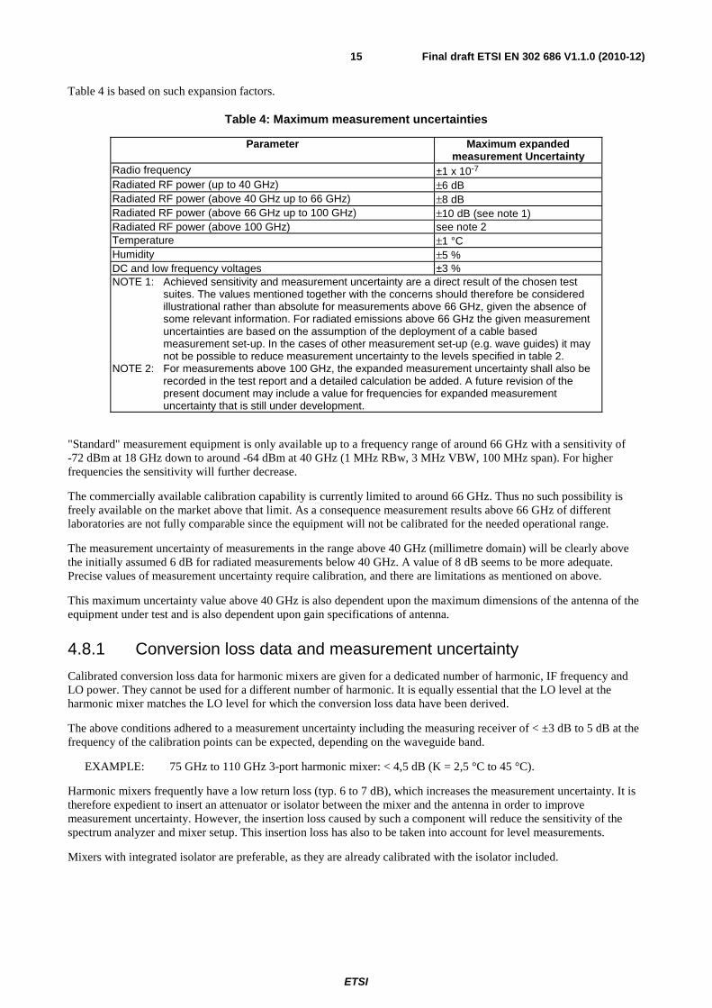
Table 4 is based on such expansion factors.
Table 4: Maximum measurement uncertainties
Parameter Maximum expanded measurement Uncertainty
Radio frequency ±1 x 10⁻⁷ Radiated RF power (up to 40 GHz) ±6 dB Radiated RF power (above 40 GHz up to 66 GHz) ±8 dB Radiated RF power (above 66 GHz up to 100 GHz) ±10 dB (see note 1) Radiated RF power (above 100 GHz) see note 2 Temperature ±1 °C Humidity ±5 % DC and low frequency voltages ±3 % NOTE 1: Achieved sensitivity and measurement uncertainty are a direct result of the chosen test
suites. The values mentioned together with the concerns should therefore be considered illustrational rather than absolute for measurements above 66 GHz, given the absence of some relevant information. For radiated emissions above 66 GHz the given measurement uncertainties are based on the assumption of the deployment of a cable based measurement set-up. In the cases of other measurement set-up (e.g. wave guides) it may not be possible to reduce measurement uncertainty to the levels specified in table 2.
NOTE 2: For measurements above 100 GHz, the expanded measurement uncertainty shall also be recorded in the test report and a detailed calculation be added. A future revision of the present document may include a value for frequencies for expanded measurement uncertainty that is still under development.
"Standard" measurement equipment is only available up to a frequency range of around 66 GHz with a sensitivity of -72 dBm at 18 GHz down to around -64 dBm at 40 GHz (1 MHz RBw, 3 MHz VBW, 100 MHz span). For higher frequencies the sensitivity will further decrease.
The commercially available calibration capability is currently limited to around 66 GHz. Thus no such possibility is freely available on the market above that limit. As a consequence measurement results above 66 GHz of different laboratories are not fully comparable since the equipment will not be calibrated for the needed operational range.
The measurement uncertainty of measurements in the range above 40 GHz (millimetre domain) will be clearly above the initially assumed 6 dB for radiated measurements below 40 GHz. A value of 8 dB seems to be more adequate. Precise values of measurement uncertainty require calibration, and there are limitations as mentioned on above.
This maximum uncertainty value above 40 GHz is also dependent upon the maximum dimensions of the antenna of the equipment under test and is also dependent upon gain specifications of antenna.
4.8.1 Conversion loss data and measurement uncertainty
Calibrated conversion loss data for harmonic mixers are given for a dedicated number of harmonic, IF frequency and LO power. They cannot be used for a different number of harmonic. It is equally essential that the LO level at the harmonic mixer matches the LO level for which the conversion loss data have been derived.
The above conditions adhered to a measurement uncertainty including the measuring receiver of < ±3 dB to 5 dB at the frequency of the calibration points can be expected, depending on the waveguide band.
EXAMPLE: 75 GHz to 110 GHz 3-port harmonic mixer: < 4,5 dB (K = 2,5 °C to 45 °C).
Harmonic mixers frequently have a low return loss (typ. 6 to 7 dB), which increases the measurement uncertainty. It is therefore expedient to insert an attenuator or isolator between the mixer and the antenna in order to improve measurement uncertainty. However, the insertion loss caused by such a component will reduce the sensitivity of the spectrum analyzer and mixer setup. This insertion loss has also to be taken into account for level measurements.
Mixers with integrated isolator are preferable, as they are already calibrated with the isolator included.

ETSI
Final draft ETSI EN 302 686 V1.1.0 (2010-12)16
As frequency ranges increase it may be difficult to conclude a maximum allowable value for the expanded measurement uncertainty due to lack of knowledge of the new methods of test and determining the uncertainty components:
• The commercially available calibration capability is limited to around 66 GHz. Thus no such possibility is freely available on the market above that limit. As a consequence measurement results above 66 GHz of different labs are not fully comparable since the equipment will not be calibrated for the needed operational range and also for radiated unwanted emission measurements above the operational range.
• The expanded measurement uncertainty of measurements in the range between 66 GHz and 100 GHz will be clearly above the values valid for below 66 GHz. Precise values of expanded measurement uncertainty require calibration, and there are limitations as mentioned above.
• In general it has to be mentioned that these values become the higher the frequency will become the more a guideline.
• Starting from around 66 GHz the limits of coaxial systems are reached and the frontend has to switch to wave guide based technologies adding an additional attenuation and also decreasing the sensitivity. Commercially available analyzers can only measure up to around 66 GHz, thus making the use of external mixers unavoidable.
Guidance is provided in TS 103 051 [i.2] that presents an evaluation of maximum acceptable measurement uncertainty for Radio Frequency (RF) electromagnetic field (emf) measurements for the frequency range from 30 MHz to 100 GHz for inclusion within ETSI documents on radio products used for compliance testing.
5 Test conditions, power sources and ambient temperatures
5.1 Normal and extreme test conditions Testing shall be made under normal test conditions, and also, where stated, under extreme test conditions.
The test conditions and procedures shall be as specified in clauses 5.2 to 5.4.
5.2 Test power source The equipment shall be tested using the appropriate test power source as specified in clauses 5.2.1 or 5.2.2. Where equipment can be powered using either external or internal power sources, then the equipment shall be tested using the external power source as specified in clause 5.2.1 then repeated using the internal power source as specified in clause 5.2.2.
The test power source used shall be stated in the test report.
5.2.1 External test power source
During testing, the power source of the equipment shall be replaced by an external test power source capable of producing normal and extreme test voltages as specified in clauses 5.3.2 and 5.4.2. The internal impedance of the external test power source shall be low enough for its effect on the test results to be negligible. For the purpose of the tests, the voltage of the external test power source shall be measured at the input terminals of the equipment. The external test power source shall be suitably de-coupled and applied as close to the equipment battery terminals as practicable. For radiated measurements, any external power leads should be so arranged so as not to affect the measurements.
During tests, the test power source voltages shall be within a tolerance of < ±1 % relative to the voltage at the beginning of each test. The value of this tolerance can be critical for certain measurements. Using a smaller tolerance will provide a better uncertainty value for these measurements.

ETSI
Final draft ETSI EN 302 686 V1.1.0 (2010-12)17
5.2.2 Internal test power source
For radiated measurements on portable equipment with integral antenna, fully charged internal batteries should be used. The batteries used should be as supplied or recommended by the provider. If internal batteries are used, at the end of each test the voltage shall be within a tolerance of < ±5 % relative to the voltage at the beginning of each test. Where this is not appropriate, a note to this effect shall be appended to the test report.
Where a test fixture is used, an external power supply at the required voltage may replace the supplied or recommended internal batteries. This shall be stated on the test report.
5.3 Normal test conditions
5.3.1 Normal temperature and humidity
The normal temperature and humidity conditions for tests shall be any convenient combination of temperature and humidity within the following ranges:
- temperature +15 °C to +35 °C;
- relative humidity 20 % to 75 %.
When it is impracticable to carry out tests under these conditions, a note to this effect, stating the ambient temperature and relative humidity during the tests, shall be added to the test report.
5.3.2 Normal test power source
5.3.2.1 Mains voltage
The normal test voltage for equipment to be connected to the mains shall be the nominal mains voltage. For the purpose of the present document, the nominal voltage shall be the declared voltage, or any of the declared voltages, for which the equipment was designed.
The frequency of the test power source corresponding to the ac mains shall be between 49 Hz and 51 Hz.
5.3.2.2 Other power sources
For operation from other power sources or types of battery (primary or secondary), the normal test voltage shall be that declared by the equipment provider and agreed by the accredited test laboratory. Such values shall be stated in the test report.
5.4 Extreme test conditions
5.4.1 Extreme temperatures
No testing shall be performed at extreme temperatures.
5.4.2 Extreme test source voltages
5.4.2.1 Mains voltage
The extreme test voltages for equipment to be connected to an ac mains source shall be the nominal mains voltage ±10 %. For equipment that operates over a range of mains voltages clause 5.4.2.4 applies.
5.4.2.2 Regulated lead-acid battery power sources
When the radio equipment is intended for operation from the usual type of regulated lead-acid battery power sources the extreme test voltages shall be 1,3 and 0,9 multiplied by the nominal voltage of the battery (6 V, 12 V, etc.).

ETSI
Final draft ETSI EN 302 686 V1.1.0 (2010-12)18
For float charge applications using "gel-cell" type batteries the extreme voltage shall be 1,15 and 0,85 multiplied by the nominal voltage of the declared battery voltage.
5.4.2.3 Power sources using other types of batteries
The lower extreme test voltages for equipment with power sources using batteries shall be as follows:
• or equipment with a battery indicator, the end point voltage as indicated;
• for equipment without a battery indicator the following end point voltages shall be used:
- for the Leclanché or the lithium type of battery:
� 0,85 multiplied by the nominal voltage of the battery.
- for the nickel-cadmium type of battery:
� 0,9 multiplied by the nominal voltage of the battery.
• for other types of battery or equipment, the lower extreme test voltage for the discharged condition shall be declared by the equipment provider.
The nominal voltage is considered to be the upper extreme test voltage in this case.
5.4.2.4 Other power sources
For equipment using other power sources, or capable of being operated from a variety of power sources, the extreme test voltages shall be those agreed between the equipment provider and the test laboratory. This shall be recorded in the test report.
6 General conditions
6.1 Normal test signals and test modulation The test modulating signal is a signal which modulates a carrier, is dependent upon the type of equipment under test and also the measurement to be performed. Modulation test signals only apply to products with an external modulation connector. For equipment without an external modulation connector, normal operating modulation shall be used.
Where appropriate, a test signal shall be used with the following characteristics:
- representative of normal operation;
- causes greatest occupied RF bandwidth.
For equipment using intermittent transmissions the test signal shall be such that:
- the generated RF signal is the same for each transmission;
- transmissions occur regularly in time;
- sequences of transmissions can be accurately repeated.
Details of the test signal shall be recorded in the test report.
Normal operating modulation shall be used, where there is no provision for external test modulation.

ETSI
Final draft ETSI EN 302 686 V1.1.0 (2010-12)19
6.1.1 Normal test signals for data
Where the equipment has an external connection for general data modulation, the normal test signals are specified as follows:
D-M2: a test signal representing a pseudo-random bit sequence of at least 511 bits in accordance with ITU-T Recommendation O.153 [3]. This sequence shall be continuously repeated. If the sequence cannot be continuously repeated, the actual method used shall be stated in the test report.
D-M3: a test signal shall be agreed between the test laboratory and the provider in case selective messages are used and are generated or decoded within the equipment. The agreed test signal may be formatted and may contain error detection and correction.
6.1.2 Product Information
The following information shall be stated by the manufacturer in order to carry out the test suites and/or to declare compliance to technical requirements for which no conformance test is included in the present document.
a) The channel plan(s), being the centre frequencies that the EUT is capable of tuning. If the equipment is capable of supporting multiple channel plans in the course of normal operation (e.g. offering different sizes of normal wideband operation), each distinct channel plan and its related occupied bandwidth for normal wideband operation must be stated.
b) The test modulation(s) used by the EUT.
c) The medium access protocol(s) used by the EUT.
d) The integral antenna design used by the equipment and measures to prevent the user from connecting a different antenna.
6.1.3 Testing of frequency agile or hopping equipment
Where possible, tests shall be carried out on a frequency within ±20 ppm of the highest frequency hop and of the lowest frequency hop.
For frequency hopping equipment specifically, three different tests shall be made under the conditions stated above:
a) The hopping sequence is stopped and the equipment is tested at two different channels as stated above.
b) The hopping sequence is in function and the equipment is tested with two hopping channels as stated above, the channels shall be visited sequentially and the number of visits to each shall be equal.
c) The hopping sequence is in normal function and the equipment is tested with all hopping channels as declared by the provider.
6.2 Test sites and general arrangements for radiated measurements
6.2.1 Test fixture
6.2.1.1 Requirements
The test fixture for radio equipment operating in the relevant frequency range shall enable the EUT to be physically supported, together with a wave-guide horn antenna Rx, which is used to measure the transmitted energy, in a fixed physical relationship to the EUT or calibration antenna Tx (see figure 2). The test fixture shall be designed for use in an anechoic environment and allow certain measurements to be performed in the far field, i.e. at a distance greater than 2d2/λ , where d is the largest dimension of the antenna aperture of the EUT.

ETSI
Final draft ETSI EN 302 686 V1.1.0 (2010-12)20
The test fixture shall incorporate at least one RF connector, a device for electromagnetic coupling to the EUT and a means for repeatable positioning of the EUT. Its compactness shall enable the whole assembly to be accommodated within a test chamber, usually a climatic facility. The circuitry associated with the RF coupling device shall not contain active or non-linear components.
Only after it has been verified that the test fixture does not affect performance of the EUT, the EUT can be confidently tested.
At set-up, the EUT shall be aligned in the test fixture so that the maximum power is detected at the coupled output (see also clause 7.1). Orientation of the horn antenna will take into account the polarization of the EUT.
In addition, the test fixture shall provide a connection to an external power supply.
The test fixture shall be provided by the provider together with a full description, which shall meet the approval of the selected accredited test laboratory.
The performance characteristics of the test fixture shall be measured and shall be approved by the accredited test laboratory. It shall conform to the following basic parameters:
• the gain of the waveguide horn shall not exceed 20 dB;
• the minimum distance between the transmitting and receiving antenna shall guarantee mutual far field conditions (distance greater than 2d2/λ , where d is the largest dimension of the antenna aperture of the EUT);
NOTE 1: Information on uncertainty contributions, and verification procedures are detailed in clauses 5 and 6, respectively, of TR 102 273-6 [4].
NOTE 2: The far field conditions of the test setup have to be carefully verified in the frequency band covered by the present document. The Voltage Standing Wave Ratio (VSWR) at the waveguide flange at which measurements are made should not be greater than 1,5.
• the performance of the test fixture when mounted in the anechoic chamber or in a temperature chamber, shall be unaffected by the proximity of surrounding objects or people inside the chamber. The performance shall be reproducible if the EUT is removed and then replaced;
• the performance of the test fixture shall remain within the defined limits of the calibration report, when the test conditions are varied over the limits described in clauses 5.3 and 5.4.
The characteristics and calibration of the test fixture shall be included in a calibration report.
6.2.1.2 Calibration
The calibration of the test fixture establishes the relationship between the detected output from the test fixture, and the transmitted power (as sampled at the position of the antenna) from the EUT in the test fixture. This can be achieved by using a calibrated horn with a gain of equal to or less than 20 dB, fed from an external signal source, in place of the EUT to determine the variations in detected power with temperature and over frequency.
The calibration of the test fixture shall be carried out by either the provider of the EUT or the accredited test laboratory. The results shall be approved by the accredited test laboratory.
The calibration should be carried out over the operating frequency band, at least three frequencies, for the declared polarization of the EUT.

ETSI
Final draft ETSI EN 302 686 V1.1.0 (2010-12)21
WaveguideHorn
Waveguide InterfaceFlange
EquipmentUnder Test
50 c
m to
60
cm
50 cm to 60 cm
15 cm Pyramidabsorber
Figure 2: Example of the test fixture
6.2.1.3 Test Sites and general arrangement
6.2.1.3.1 Open Area Test Site (OATS)
An Open Area Test Site comprises a turntable at one end and an antenna mast of variable height at the other set above a ground plane which, in the ideal case, is perfectly conducting and of infinite extent. In practice, whilst good conductivity can be achieved, the ground plane size has to be limited. A typical Open Area Test Site is shown in figure 3.
Range length 3 m or 10 m
Turntable
Ground plane
Dipole antennas
Antenna mast
Figure 3: A typical Open Area Test Site
The ground plane creates a wanted reflection path, such that the signal received by the receiving antenna is the sum of the signals received from the direct and reflected transmission paths. The phasing of these two signals creates a unique received level for each height of the transmitting antenna (or EUT) and the receiving antenna above the ground plane.
In practice, the antenna mast provides a variable height facility so that the elevation of the test antenna can be optimized for maximum coupled signal in conjunction with the turntable for azimuth angle.

ETSI
Final draft ETSI EN 302 686 V1.1.0 (2010-12)22
Both absolute and relative measurements can be performed on an Open Area Test Site. Where absolute measurements are to be carried out, or where the test site is to be used for accredited measurements, the Open Area Test Site should be verified. Verification involves comparison of the measured performance to that of an ideal theoretical site, with acceptability being decided on the basis of the differences not exceeding some pre-determined limits.
The Open Area Test Site has been, historically, the reference site upon which the majority, if not all, of the specification limits have been set. The ground plane was originally introduced to provide uniformity of ground conditions, between test sites, during testing.
6.2.1.3.2 Other test sites
The test sites described below are equipped with absorbers for attenuation of reflections. These absorbers' efficiency is subject to a lower and an upper cut-off frequency. For the use at higher frequencies suitability of these test sites has to be verified with regard to attenuation of reflections, resonances in connection with the chamber as well as imaging.
6.2.1.3.3 Semi-Anechoic Rooms with a conductive Ground Plane
A Semi-Anechoic Room with a conductive Ground Plane is an enclosure, usually shielded, whose internal walls and ceiling are covered with radio absorbing material, normally of the pyramidal urethane foam type. The floor, which is metallic, is not covered and forms the ground plane. The room usually contains an antenna mast at one end and a turntable at the other. A typical Semi-Anechoic Room with a conductive Ground Plane is shown in figure 4.
Range length 3 m or 10 mTurntable
Testantenna
Antenna mast
Ground plane
Radioabsorbingmaterial
Figure 4: A typical Anechoic Chamber with a Ground Plane
This type of test room attempts to simulate an ideal Open Area Test Site (historically, the reference site upon which the majority, if not all, of the specification limits have been set) whose primary characteristic is a perfectly conducting ground plane of infinite extent.
The room shielding and radio absorbing material work together to provide a controlled environment for testing purposes. The shielding provides a test space with reduced levels of interference from ambient signals and other outside effects, whilst the radio absorbing material minimizes unwanted reflections from the walls and ceiling which can influence the measurements.

ETSI
Final draft ETSI EN 302 686 V1.1.0 (2010-12)23
In practice whilst it is relatively easy for shielding to provide high levels (80 dB to 140 dB) of ambient interference rejection (normally making ambient interference negligible), no design of radio absorbing material satisfies the requirement of complete absorption of all the incident power. For example it cannot be perfectly manufactured and installed and its return loss (a measure of its efficiency) varies with frequency, angle of incidence and in some cases, is influenced by high power levels of incident radio energy. To improve the return loss over a broader frequency range, ferrite tiles, ferrite grids and hybrids of urethane foam and ferrite tiles are used with varying degrees of success.
The ground plane creates the wanted reflection path, such that the signal received by the receiving antenna is the sum of the signals received from the direct and reflected transmission paths. The phasing of these two signals creates a unique received signal level for each height of the transmitting antenna (or EUT) and the receiving antenna above the ground plane.
In practice, the antenna mast provides a variable height facility so that the elevation of the test antenna can be optimized for maximum coupled signal in conjunction with the turntable for azimuth angle, between antennas, or, between an EUT and a test antenna.
Both absolute and relative measurements can be performed in a Semi-Anechoic Room with a Ground Plane. Where absolute measurements are to be carried out, or where the test facility is to be used for accredited measurements, the chamber should be verified. Verification involves comparison of the measured performance to that of an ideal theoretical room, with acceptability being decided on the basis of the differences not exceeding some pre-determined limits.
6.2.1.3.4 Fully Anechoic Rooms (FAR)
A FullyAnechoic Room is an enclosure whose internal walls, floor and ceiling are covered with radio absorbing material, normally of the pyramidal urethane foam type. It is normally shielded against local ambients. The room contains an antenna support at one end and a turntable at the other. A typical Anechoic Room is shown in figure 5 with dipole antennas at both ends.
Range length 3m or 10 m
Turntable
Antenna support
Antenna support
Radioabsorbingmaterial
Dipole antennas
Figure 5: A typical Anechoic Chamber
The room shielding and radio absorbing material work together to provide a controlled environment for testing purposes. This type of test room attempts to simulate free space conditions. The shielding provides a test space, with reduced levels of interference from ambient signals and other outside effects, whilst the radio absorbing material minimizes unwanted reflections from the walls, floor and ceiling which could influence the measurements.

ETSI
Final draft ETSI EN 302 686 V1.1.0 (2010-12)24
In practice whilst it is relatively easy for the shielding to provide high levels (80 dB to 140 dB) of ambient interference rejection (normally making ambient interference negligible), no design of radio absorbing material satisfies the requirement of complete absorption of all the incident power. For example it cannot be perfectly manufactured and installed and its return loss (a measure of its efficiency) varies with frequency, angle of incidence and in some cases, is influenced by high power levels of incident radio energy. To improve the return loss over a broader frequency range, ferrite tiles, ferrite grids and hybrids of urethane foam and ferrite tiles are used with varying degrees of success.
The Anechoic Room generally has several advantages over other test facilities. There is minimal ambient interference, minimal floor, ceiling and wall reflections and it is independent of the weather. It does however have some disadvantages which include limited measuring distance (due to available room size, cost, etc.) and limited lower frequency usage due to the size of the room and the pyramidal absorbers.
Both absolute and relative measurements can be performed in a Fully Anechoic Room. Where absolute measurements are to be carried out, or where the test facility is to be used for accredited measurements, the room should be verified. Verification involves comparison of the measured performance to that of an ideal theoretical chamber, with acceptability being decided on the basis of the maximum difference between the two.
A typical anechoic chamber is shown in figure 6. This type of test chamber attempts to simulate free space conditions.
Absorber
Absorber
Abs
orbe
r
Abs
orbe
r
Reference points
Test antenna
h
dd1 d2
d4
d6
d3
d5
Non-conductive supports
EUT
ϕ
θ
Shielding
γ
Figure 6: Typical anechoic chamber
The chamber contains suitable antenna supports on both ends.
The supports carrying the test antenna and EUT shall be made of a low micro-wave loss material featuring a low value of its relative permittivity.
The anechoic chamber shall be shielded. Internal walls, floor and ceiling shall be covered with radio absorbing material. The shielding and return loss for perpendicular wave incidence vs. frequency. In the measurement frequency range it shall meet:
• 105 dB shielding loss;
• 30 dB return loss.
Both absolute and relative measurements can be performed in an anechoic chamber. Where absolute measurements are to be carried out the chamber shall be verified.
The shielded anechoic chamber test site shall be calibrated and validated for the frequency range being applicable.

ETSI
Final draft ETSI EN 302 686 V1.1.0 (2010-12)25
NOTE 1: Information on uncertainty contributions, and verification procedures are detailed in clauses 5 and 6, respectively, of TR 102 273-2 [4].
NOTE 2: The presented test fixture and procedures are based on the best practice in lower frequency bands. The setup might need to be adapted to the specific need of the millimetre wave systems especially above 100 GHz. The measurement reports should clearly document the used setup of the test fixture. The presented test fixture is mainly intended to be used for power measurements as defined in the scope of the present document.
When measuring in an anechoic chamber above 1 GHz and without a height scan of the "comparison antenna", instead of performing 360° increments with a turntable the EUT would have to be moved orthogonally around all its surfaces in order to measure the maximum radiated RF power due to the narrow antenna pattern occurring at high frequencies.
6.2.1.3.5 Minimum requirements for test sites for measurements above 18 GHz
Generally the test site shall be adequate to allow for testing in the far field of the EUT. The test site should therefore consist of an electromagnetic anechoic room where either at least the ground surface is covered with radio absorbing material or up to six surrounding surfaces are covered with radio absorbing material. The absorbing material shall have a minimum attenuation of 30 dB. It shall be verified that reflections are sufficiently reduced. The test site shall have the following dimensions:
• Width of 2 meters.
• Length of 3 meters.
• Height of 2 meters (only applicable for a room with more than one reflecting surface).
Highly directional receiving antennas help in reducing reflections. The use of standard gain horn antennas is recommended. It shall be noted that if the antenna aperture is smaller than the EUT, sufficient measurements in both azimuth and elevation shall be conducted in order to ensure that the maximum radiation is determined.
The measuring distance shall be selected in such way that antenna coupling effects are avoided. A distance of at least 0,5 m is therefore recommended. The EUT may be positioned at any height that minimizes reflections from the floor.
Due to high loss of coaxial cables at higher frequencies, the connection from the receiving antenna to the measuring receiver should not exceed 1 m, thus making it necessary to place the measuring receiver very close. This is especially the case when using external harmonic mixers with very short connections to the measuring receiver. Therefore the measuring receiver should somehow be covered with radio absorbing material in direction to the measuring field in order to reduce reflections. Figure 7 shows an example of a test site above 18 GHz with one reflecting surface.
Receiving antenna or harmonic mixer with antenna
Measuring receiver
Radio absorbing material
EUT
Non conductive material
Coaxial cable
Site attenuation
Figure 7: Example of a test site above 18 GHz with one reflecting surface

ETSI
Final draft ETSI EN 302 686 V1.1.0 (2010-12)26
The site attenuation of the test site can be determined. Should the test site in its characteristics be nearly ideal, it may be possible to use the theoretical Free Space Loss (FSL) as site attenuation as shown in the examples in the tables 5 to 7.
Table 5: Example of Free Space Loss at 1 m distance
Measuring distance/m f/GHz λ/ 1 m [FSL]/dB
1
24,2 0,01239 60,12 48,4 0,006198 66,14 72,6 0,004132 69,66 96,8 0,003099 72,16
Table 6: Example of Free Space Loss at 0,5 m distance
Measuring distance/m f/GHz λ/ 1 m [FSL]/dB
0,5
24,2 0,012397 54,1 48,4 0,006198 60,12 72,6 0,004132 63,64 96,8 0,003099 66,14
Table 7: Example of Free Space Loss at 0,25 m distance
Measuring distance/m f/GHz λ/ 1 m [FSL]/dB
0,25 72,6 0,004132 57,62 96,8 0,003099 60,12
Whereas:
λ = c/f
[FSL] = 10 log (4πr/λ)2
6.3 Measuring receiver The term "measuring receiver" refers to a frequency-selective voltmeter or a spectrum analyser. The measurement bandwidth of the measuring receiver shall, where possible, be according to CISPR 16 [2]. In order to obtain the required sensitivity, a narrower measurement bandwidth may be necessary. In such cases, this shall be stated in the test report form. The bandwidth of the measuring receiver and the deployed detectors shall be as given in table 8.
Table 8: Measurement receiver parameters
Frequency range: (f) Measuring receiver bandwidth Detector 30 MHz ≤ f ≤ 1 000 MHz 100 kHz or 120 kHz peak/RMS (see note 1) 1 000 MHZ < f ≤ 40GHz 1 MHz peak/RMS
f > 40 GHz 1 MHz (see note 2) peak/RMS NOTE 1: With the values from the peak and the RMS detector the quasi peak value can be calculated for
particular measurement applications. NOTE 2: The actual frequency accuracy shall be taken into account to determine the minimum
measurement bandwidth possible.
In case a narrower measurement bandwidth was used, the following conversion formula has to be applied:
MEASUREDBW
BWrefAB log10+=

ETSI
Final draft ETSI EN 302 686 V1.1.0 (2010-12)27
Where:
• A is the value at the narrower measurement bandwidth;
• B is the value referred to the reference bandwidth; or
• use the measured value, A, directly if the measured spectrum is a discrete spectral line. (A discrete spectrum line is defined as a narrow peak with a level of at least 6 dB above the average level inside the measurement bandwidth.)
6.4 Antennas
6.4.1 Test antenna
A test antenna is always used in radiated test methods. In emission tests (i.e. effective radiated power, radiated spurious emissions) the test antenna is used to detect the field from the EUT in one stage of the measurement and from the substitution antenna in the other stage. For tests of receiver parameter of EUTs with integrated or dedicated antennas (i.e. sensitivity, blocking, adjacent channel selectivity, etc.) the test antenna is used to radiate a field to the EUT or to the substitution antenna.
The test antenna should be mounted on a support capable of allowing the antenna to be used in either horizontal or vertical polarization. On ground plane sites (i.e. anechoic chambers with ground planes and Open Area Test Sites), the test antenna should additionally allow the height of its centre above the ground to be varied over the specified range (usually 1 m to 4 m).
For the test in the frequency range from 30 MHz to 1 000 MHz a biconical and a log periodical dipole array antenna or combination thereof (commonly termed "log periodic") could be used to cover the entire band. Above 1 000 MHz waveguide horns are recommended although, again, log periodic could be used.
The length of the test antenna along the measurement axis shall not exceed 20 % of the measuring distance. Furthermore the distance between the lower extremity of the measuring antenna and the ground shall be at least 300 mm.
NOTE 1: The gain of a horn antenna is generally expressed relative to an isotropic radiator.
For radiated measurements of transmitters, the test antenna is connected to a calibrated measuring receiver capable of being tuned to any frequency under investigation. The test antenna is connected to a calibrated signal generator for receiver parameter tests.
NOTE 2: The use of filters may be necessary in order to suppress certain wanted signals.
6.4.2 Substitution antenna
The substitution antenna is used to replace the EUT for tests in which transmitting parameters (i.e. effective radiated power, radiated spurious emissions) are being measured. In this case the antenna acts as a reference radiator to transmit a known radiated power.
The substitution antenna is also used to measure a certain field at the position of the EUT for receiver parameter measurements.
In the frequency band 30 MHz to 1 000 MHz, the substitution antenna should be a λ/2 dipole antenna. For frequencies of 80 MHz and above, the dipoles should have their arm lengths set for resonance at the frequency of test. Below 80 MHz, shortened arm lengths are recommended. Where a shortened dipole antenna is used at these frequencies, details of the type of antenna used shall be included with the results of the tests and correction factors shall be taken into account. For measurements above 1 000 MHz, a standard gain horn or calibrated horn antenna is recommended although, log periodic could be used.
The centre of this antenna shall coincide with the reference point of the EUT it has replaced. This reference point shall be the volume centre of the sample when its antenna is mounted inside the cabinet or the point where an outside antenna is connected to the cabinet. The distance between the lower extremity of the dipole and the ground shall be at least 300 mm. Usually the centre of a horn antenna is defined as the aperture plane.

ETSI
Final draft ETSI EN 302 686 V1.1.0 (2010-12)28
For radiated measurements of transmitter parameters or receiver spurious emission the substitution antenna is connected to a calibrated signal generator capable to generate levels to any frequencies under investigation.
The substitution antenna shall be connected to a calibrated measuring receiver when the site is used for the measurement of receiver parameters. The signal generator and the receiver shall be connected to the antenna through suitable matching and balancing networks.
The substitution antenna shall be moved through a distance of ±0,1 m in the direction of the test antenna as well as in the two directions perpendicular to this first direction to find the position of maximum response.
6.4.3 Signalling antenna
In certain cases the EUT requires some signalling in order to provide its operating or test modes which can be affected by a corresponding signalling antenna. It shall be ensured that this antenna has no coupling effects against the test or substitution antenna.
7 Methods of measurement and limits for transmitter parameters
Where the transmitter is designed with adjustable carrier power clause 4.2.2 applies.
When performing transmitter tests on equipment designed for intermittent operation it may be necessary to exceed the duty cycle associated with normal operation. The maximum transmit on-time shall be stated by the test laboratory where applicable. This on-time shall not be exceeded and details shall be stated in the test report.
For frequency hopping spread spectrum (FHSS) the equipment shall be programmed so that measurements can be performed on selected single carrier or hop frequencies as described in clause 6.1.3.
Only radiated measurements shall be performed.
The equipment shall fulfil the requirements of the stated measurements.
7.1 RF output power (mean e.i.r.p.)
7.1.1 Definition
The RF output power is the mean equivalent isotropic radiated power (e.i.r.p.) for the equipment during a transmission burst. The mean e.i.r.p. refers to the highest power level of the transmitter power control range during the transmission cycle if the transmitter power control is implemented.
7.1.2 Limit
The maximum RF output power is applicable to the system as a whole when operated at the highest stated power level. For a smart antenna system and directional antennas, the limit applies to the configuration which results in the highest e.i.r.p..
The maximum RF output power in normal wideband operation shall be limited by usage as indicated in table 9.
Table 9: RF output power limit
Frequency Bands RF output power Application Notes
63 GHz to 64 GHz 40 dBm e.i.r.p. Non-specific ITS An antenna gain of at least 20 dBi is
included

ETSI
Final draft ETSI EN 302 686 V1.1.0 (2010-12)29
7.1.3 Conformance
The RF output power, subject to the conditions outlined in clause 5, shall be measured using a test site as described in clause 6 shall be measured and recorded for conformance. These measurements shall be performed under both normal and extreme operating conditions.
The centre frequency of all equipment shall be verified as being in the specified bands.
Step 1:
a) Using suitable attenuators, the measurement equipment shall be coupled to a matched diode detector or equivalent thereof. The output of the diode detector shall be connected to the vertical channel of an oscilloscope or equivalent power measurement equipment.
b) The combination of the diode detector and the oscilloscope shall be capable of faithfully reproducing the duty cycle of the transmitter output signal.
c) The observed duty cycle of the transmitter (Tx on / (Tx on + Tx off)) shall be noted as x (0,1 < x ≤ 1), and recorded in the test report. For the purpose of testing, the equipment shall be operated with a duty cycle that is equal to or greater than 0,1.
Step 2:
a) The RF output power of the transmitter when operated at the highest power level shall be measured using a spectrum analyser with an integration factor that exceeds the repetition period of the transmitter by a factor of 5 or more. The used detector shall be a RMS detector with averaging. The observed value shall be noted as "A" (in dBm).
b) The e.i.r.p. shall be calculated from the above measured power output A (in dBm) and the observed duty cycle x according to the formula below shall be recorded.
c) PH = A + 10 × log10 (1 / x).
7.2 Permitted range of operating frequencies The frequency range of the equipment is determined by the lowest and highest frequencies occupied by the power envelope in accordance with table 9.
FH is the highest frequency of the power envelope. It is the frequency furthest above the frequency of maximum power
where the output power envelope drops below the level of -29 dBm / 200 MHz.
FL is the lowest frequency of the power envelope. It is the frequency furthest below the frequency of maximum power
where the output power drops below the level of -29 dBm / 200 MHz.
The power envelope shall contain the occupied bandwidth representing at least 99 % of the emissions energy.
The occupied and necessary bandwidths of the transmitter shall be specified. Where differing modes of emission are available, all modes and their associated bandwidths shall be stated.
7.2.1 Definition
The permitted range of operating frequencies includes all frequencies on which the equipment may operate within an assigned frequency band. The operating frequency range shall be declared by the manufacturer.
The range of frequencies, determined by clause 7.1.2, table 9, shall be specified in the test report.
7.2.2 Method of measurement
The method of measurement for equipment employing FHSS and stepped frequency modulation is given in clause 7.2.3.
Using applicable measurement procedures the frequency range(s) shall be measured and recorded in the test report.

ETSI
Final draft ETSI EN 302 686 V1.1.0 (2010-12)30
Where applicable, during these measurements the test data sequence as specified in clauses 6.1 and 6.1.1 shall be used. The transmitter power level shall be set to the rated power level.
These measurements shall be performed under both normal and extreme operating conditions except for the occupied bandwidth assessment for which measurement at normal operating conditions is sufficient.
The measurement procedure shall be as follows:
a) put the spectrum analyser in video averaging mode with a minimum of 50 sweeps selected;
b) select the lowest operating frequency of the equipment under test and activate the transmitter with modulation applied. The RF emission of the equipment shall be displayed on the spectrum analyser;
c) using the marker of the spectrum analyser, find the lowest frequency below the operating frequency at which the spectral power density drops below the level given in clause 7.2. This frequency shall be recorded in the test report;
d) select the highest operating frequency of the equipment under test and find the highest frequency at which the spectral power density drops below the value given in clause 7.2. This frequency shall be recorded in the test report;
e) the difference between the frequencies measured in steps c) and d) is the operating frequency range. It shall be recorded in the test report.
This measurement shall be repeated for each frequency range declared by the manufacturer (in case of several sub-frequency ranges within the 63 GHz to 64 GHz frequency band).
7.2.3 Method of measurement for equipment using FHSS modulation
Using an applicable measurement procedure the frequency range of the equipment shall be measured and recorded in the test report.
During these measurements the test data sequence, as specified in clause 6.1, shall be used.
The transmitter power level shall be set to the rated power level.
These measurements shall be performed under both normal and extreme operating conditions.
The measurement procedure shall be as follows:
a) put the spectrum analyser in video averaging mode with a minimum of 50 sweeps selected;
b) select the lowest hop frequency of the equipment under test and activate the transmitter with modulation applied;
c) find the lowest frequency below the operating frequency at which the spectral power density drops below the level given in clause 7.2. This frequency shall be recorded in the test report;
d) select the highest hop frequency of the equipment under test and find the highest frequency at which the spectral power density drops below the level given in clause 7.2. This frequency shall be recorded in the test report;
e) the difference between the frequencies measured in steps c) and d) is the frequency range. It shall be recorded in the test report.
This measurement shall be repeated for each frequency range declared by the manufacturer (in case of several sub-frequency ranges within the 63 GHz to 64 GHz frequency band).
7.2.4 Limit
The width of the power spectrum envelope is fH - fL for a given operating frequency. In equipment that allows
adjustment or selection of different operating frequencies, the power envelope takes up different positions in the allowed band. The frequency range is determined by the lowest value of fL and the highest value of fH resulting from
the adjustment of the equipment to the lowest and highest operating frequencies.
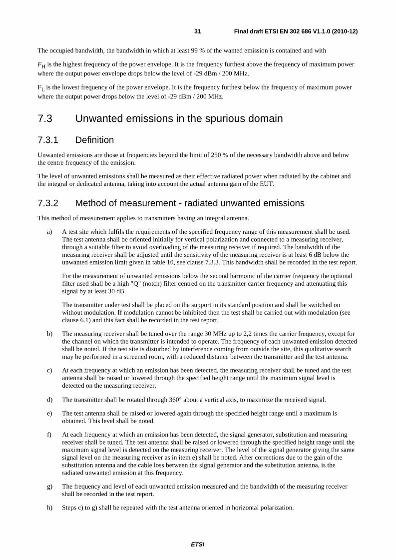
ETSI
Final draft ETSI EN 302 686 V1.1.0 (2010-12)31
The occupied bandwidth, the bandwidth in which at least 99 % of the wanted emission is contained and with
FH is the highest frequency of the power envelope. It is the frequency furthest above the frequency of maximum power
where the output power envelope drops below the level of -29 dBm / 200 MHz.
FL is the lowest frequency of the power envelope. It is the frequency furthest below the frequency of maximum power
where the output power drops below the level of -29 dBm / 200 MHz.
7.3 Unwanted emissions in the spurious domain
7.3.1 Definition
Unwanted emissions are those at frequencies beyond the limit of 250 % of the necessary bandwidth above and below the centre frequency of the emission.
The level of unwanted emissions shall be measured as their effective radiated power when radiated by the cabinet and the integral or dedicated antenna, taking into account the actual antenna gain of the EUT.
7.3.2 Method of measurement - radiated unwanted emissions
This method of measurement applies to transmitters having an integral antenna.
a) A test site which fulfils the requirements of the specified frequency range of this measurement shall be used. The test antenna shall be oriented initially for vertical polarization and connected to a measuring receiver, through a suitable filter to avoid overloading of the measuring receiver if required. The bandwidth of the measuring receiver shall be adjusted until the sensitivity of the measuring receiver is at least 6 dB below the unwanted emission limit given in table 10, see clause 7.3.3. This bandwidth shall be recorded in the test report.
For the measurement of unwanted emissions below the second harmonic of the carrier frequency the optional filter used shall be a high "Q" (notch) filter centred on the transmitter carrier frequency and attenuating this signal by at least 30 dB.
The transmitter under test shall be placed on the support in its standard position and shall be switched on without modulation. If modulation cannot be inhibited then the test shall be carried out with modulation (see clause 6.1) and this fact shall be recorded in the test report.
b) The measuring receiver shall be tuned over the range 30 MHz up to 2,2 times the carrier frequency, except for the channel on which the transmitter is intended to operate. The frequency of each unwanted emission detected shall be noted. If the test site is disturbed by interference coming from outside the site, this qualitative search may be performed in a screened room, with a reduced distance between the transmitter and the test antenna.
c) At each frequency at which an emission has been detected, the measuring receiver shall be tuned and the test antenna shall be raised or lowered through the specified height range until the maximum signal level is detected on the measuring receiver.
d) The transmitter shall be rotated through 360° about a vertical axis, to maximize the received signal.
e) The test antenna shall be raised or lowered again through the specified height range until a maximum is obtained. This level shall be noted.
f) At each frequency at which an emission has been detected, the signal generator, substitution and measuring receiver shall be tuned. The test antenna shall be raised or lowered through the specified height range until the maximum signal level is detected on the measuring receiver. The level of the signal generator giving the same signal level on the measuring receiver as in item e) shall be noted. After corrections due to the gain of the substitution antenna and the cable loss between the signal generator and the substitution antenna, is the radiated unwanted emission at this frequency.
g) The frequency and level of each unwanted emission measured and the bandwidth of the measuring receiver shall be recorded in the test report.
h) Steps c) to g) shall be repeated with the test antenna oriented in horizontal polarization.

ETSI
Final draft ETSI EN 302 686 V1.1.0 (2010-12)32
i) If a user accessible power adjustment is provided then the tests in steps c) to h) shall be repeated at the lowest power setting available.
j) Steps c) to h) shall be repeated with the transmitter in the standby condition if this option is available.
The sensitivity of the spectrum analyser should be such that the noise floor is at least 6 dB below the limits given in table 10. To improve the sensitivity of the measuring receiver, the measurement bandwidth can be reduced or the measurement distance can be reduced. If this is not practical anymore, the achievable measurement noise floor shall be recorded and reported.
In accordance with recommends 3) of ERC/REC 74.01 [i.6], the spurious domain emission limits are applicable up to the second harmonic. However, for practical measurement purposes only, the frequency range of spurious emissions may be restricted. This shall be recorded in the test report.
7.3.3 Limits
The power of any unwanted emission in the spurious domain shall not exceed the values given in table 10 assuming a 0 dBi antenna gain.
Table 10: Unwanted emissions
Frequency ranges
47 MHz to 74 MHz 87,5 MHz to 108 MHz 174 MHz to 230 MHz 470 MHz to 862 MHz
(see note 1)
Other frequencies ≤ 1 000 MHz (see note 1)
F > 1 000 MHz (see notes 1 and 2)
State
Operating 4 nW (-54 dBm) 250 nW (-36 dBm) 1 μW (-30 dBm) Standby 2 nW (-57 dBm) 2 nW (-57 dBm) 20 nW (-47 dBm)
NOTE 1: The applicable measurement bandwidth for frequencies below 1 GHz is 100 kHz while the applicable measurement bandwidth for frequencies above 1 GHz is 1 MHz.
NOTE 2: The upper frequency limit for unwanted emissions is to include the second harmonic of the EUT. However, for practical measurement purposes only, the frequency range of spurious emissions may be restricted. This shall be recorded in the test report.
8 Receiver If the receiver is equipped with a battery-saving circuit, this circuit shall be made inoperative for the duration of the tests.
8.1 Unwanted emissions These requirements do not apply to receivers used in combination with permanently co-located transmitters continuously transmitting.
8.1.1 Definition
Unwanted radiations from the receiver are components at any frequency, radiated by the equipment and antenna.
The level of unwanted radiations shall be measured by their effective radiated power when radiated by the cabinet and the integral or dedicated antenna.

ETSI
Final draft ETSI EN 302 686 V1.1.0 (2010-12)33
8.1.2 Method of measurement radiated unwanted components
a) A test site which fulfils the requirements of the specified frequency range of this measurement shall be used. The test antenna shall be oriented initially for vertical polarization and connected to a measuring receiver. The bandwidth of the measuring receiver shall be adjusted until the sensitivity of the measuring receiver is at least 6 dB below the unwanted emission limit given in clause 8.1.3. This bandwidth shall be recorded in the test report.
The receiver under test shall be placed on the support in its standard position.
b) The measuring receiver shall be tuned over the range 30 MHz up to 2,2 times the carrier frequency. The frequency of each unwanted component shall be noted. If the test site is disturbed by radiation coming from outside the site, this qualitative search may be performed in a screened room with reduced distance between the transmitter and the test antenna.
c) At each frequency at which a component has been detected, the measuring receiver shall be tuned and the test antenna shall be raised or lowered through the specified height range until the maximum signal level is detected on the measuring receiver.
d) The receiver shall be rotated up to 360° about a vertical axis, to maximize the received signal.
e) The test antenna shall be raised or lowered again through the specified height range until a maximum is obtained. This level shall be noted.
f) At each frequency at which a component has been detected, the signal generator, substitution antenna and measuring receiver shall be tuned. The test antenna shall be raised or lowered through the specified height range until the maximum signal level is detected on the measuring receiver. The level of the signal generator giving the same signal level on the measuring receiver as in step e) shall be noted. This level, after correction due to the gain of the substitution antenna and the cable loss, is the radiated unwanted component at this frequency.
g) The frequency and level of each unwanted emission measured and the bandwidth of the measuring receiver shall be recorded in the test report.
h) Measurements b) to g) shall be repeated with the test antenna oriented in horizontal polarization.
In accordance with of ERC/REC 74.01 [i.6], the spurious domain emission limits are applicable up to the second harmonic. To improve the sensitivity of the measuring receiver, the measurement bandwidth can be reduced or the measurement distance can be reduced. If this is not practical anymore, the achievable measurement noise floor shall be recorded and reported, i.e. for practical measurement purposes only, the frequency range of spurious emissions may be restricted. This shall be recorded in the test report.
8.1.3 Limits
The power of any unwanted emission:
1) shall not exceed 2 nW (-57 dBm) in the range 30 MHz to 1 GHz;
2) shall not exceed 20 nW (-47 dBm in reference measurement bandwidth of 1 MHz) on frequencies above 1 GHz. The upper frequency is to include the second harmonic of the EUT.
The measured unwanted emissions shall be stated in the test report.

ETSI
Final draft ETSI EN 302 686 V1.1.0 (2010-12)34
Annex A (normative): HS Requirements and conformance Test specifications Table (HS-RTT) The HS Requirements and conformance Test specifications Table (HS-RTT) in table A.1 serves a number of purposes, as follows:
• it provides a statement of all the requirements in words and by cross reference to (a) specific clause(s) in the present document or to (a) specific clause(s) in (a) specific referenced document(s);
• it provides a statement of all the test procedures corresponding to those requirements by cross reference to (a) specific clause(s) in the present document or to (a) specific clause(s) in (a) specific referenced document(s);
• it qualifies each requirement to be either:
- Unconditional: meaning that the requirement applies in all circumstances; or
- Conditional: meaning that the requirement is dependent on the manufacturer having chosen to support optional functionality defined within the schedule;
• in the case of Conditional requirements, it associates the requirement with the particular optional service or functionality;
• it qualifies each test procedure to be either:
- Essential: meaning that it is included with the Essential Radio Test Suite and therefore the requirement shall be demonstrated to be met in accordance with the referenced procedures;
- Other: meaning that the test procedure is illustrative but other means of demonstrating compliance with the requirement are permitted.
Table A.1: HS Requirements and conformance Test specifications Table (HS-RTT)
Harmonized Standard EN 302 686 The following requirements and test specifications are relevant to the presumption of conformity
under article 3.2 of the R&TTE Directive Requirement Requirement Conditionality Test Specification
No Description Reference: Clause No
U/C Condition E/O Reference: Clause No
1 RF output power (mean e.i.r.p.)
7.1.2 U E 7.1.3
2 Permitted range of operating frequencies
7.2.4 U E 7.2.2 or 7.2.3
3 Transmitter unwanted emissions in the spurious domain
7.3.3 U E 7.3.2
4 Receiver spurious components 8.1.3 U E 8.1.2
Key to columns:
Requirement:
No A unique identifier for one row of the table which may be used to identify a requirement or its test specification.
Description A textual reference to the requirement.
Clause Number Identification of clause(s) defining the requirement in the present document unless another document is referenced explicitly.

ETSI
Final draft ETSI EN 302 686 V1.1.0 (2010-12)35
Requirement Conditionality:
U/C Indicates whether the requirement is to be unconditionally applicable (U) or is conditional upon the manufacturers claimed functionality of the equipment (C).
Condition Explains the conditions when the requirement shall or shall not be applicable for a technical requirement which is classified "conditional".
Test Specification:
E/O Indicates whether the test specification forms part of the Essential Radio Test Suite (E) or whether it is one of the Other Test Suite (O).
NOTE: All tests whether "E" or "O" are relevant to the requirements. Rows designated "E" collectively make up the Essential Radio Test Suite; those designated "O" make up the Other Test Suite; for those designated "X" there is no test specified corresponding to the requirement. The completion of all tests classified "E" as specified with satisfactory outcomes is a necessary condition for a presumption of conformity. Compliance with requirements associated with tests classified "O" is a necessary condition for presumption of conformity, although conformance with the requirement may be claimed by an equivalent test or by manufacturer's assertion supported by appropriate entries in the technical construction file.
Clause Number Identification of clause(s) defining the test specification in the present document unless another document is referenced explicitly Where no test is specified (that is, where the previous field is "X") this field remains blank.

ETSI
Final draft ETSI EN 302 686 V1.1.0 (2010-12)36
Annex B (normative): Radiated measurements
B.1 Substitution method The substitution method can be used even without proven suitability of the test site since the errors of the test site at certain frequencies are constant and become compensated by the substitution. Accuracy of the substitution predominantly depends on the accuracy of the RF source's indicator and the exact gain specification of the substitution antenna.
B.1.1 Principle of the substitution measurement method When assessing the radiated power with the substitution method the peak power is evaluated. Due to a vast compensation of the failure impacts of the "comparison test site" the measurement uncertainty can be significantly reduced. Disadvantage of this method is that it causes increased time expenditure when a lot of values have to be determined for a EUT.
On the one hand a substitution test site comprises a suitable "comparison test site" (blue boxes). This site consists of an antenna without factors (1), whereas this antenna shall provide sufficient aperture angle, a height adjustable support (2), an antenna cable (3) as well as an indicator (4) consisting of a measuring receiver or a spectrum analyzer or a power meter.
Figure B.1: Illustration of the first step of the substitution method
In the first step of the substitution method the maximum radiated level of an EUT is determined. This level has no unit and does not represent a measured value. It just shows an indication value.
The substitution test site (red box) consists of an unmodulated generator, variable in frequency and power, with a power that is traceable due to calibration or alternatively a calibrated power meter (1), a suitable 50 Ohm cable with indication of the cable loss (2), a suitable, calibrated attenuator (3) for coercive adaption to the antenna, consisting of real active resistances, an antenna support without influence on the test result (4) as well as a standard dipole up to 1 GHz or respectively an antenna with indication of the calibrated, isotropic gain (5).
EUT
1
2
3
4
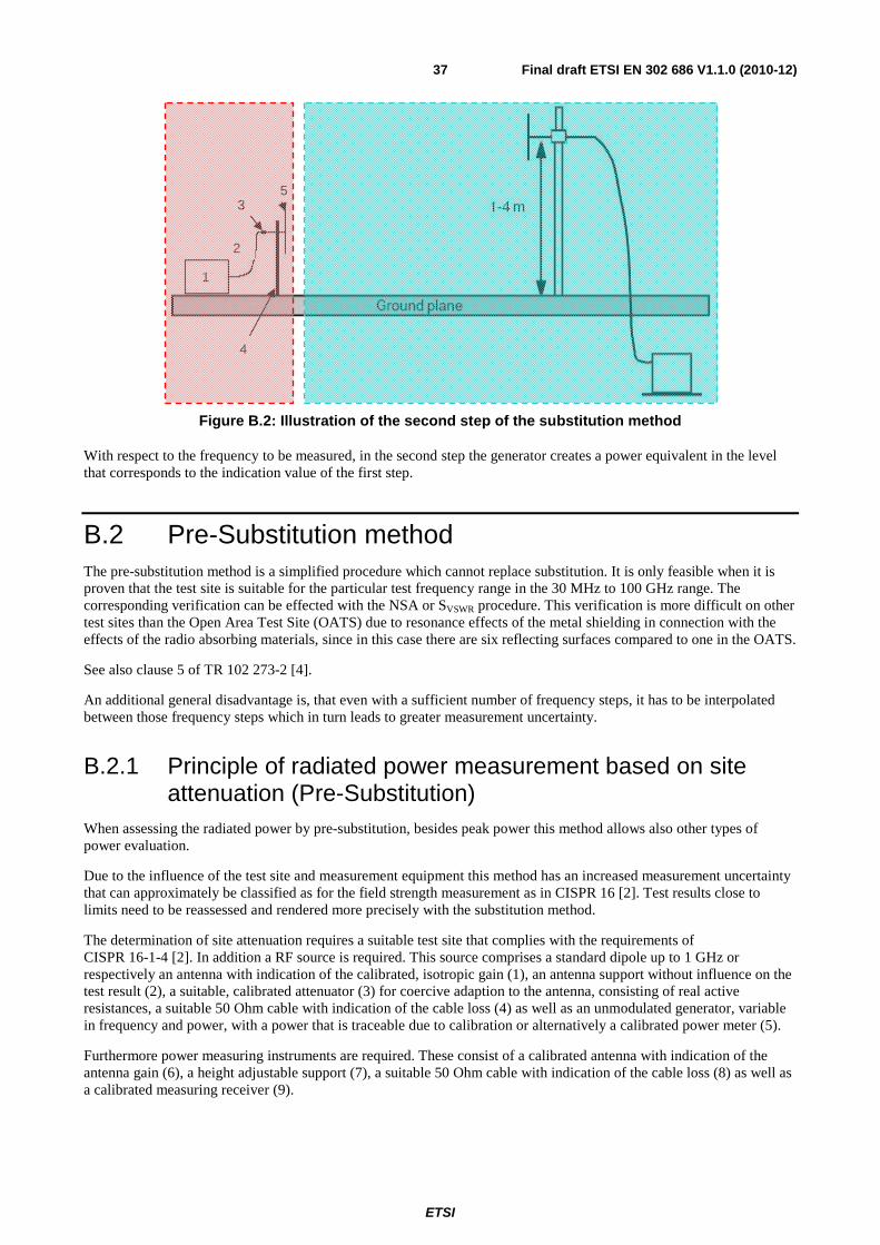
ETSI
Final draft ETSI EN 302 686 V1.1.0 (2010-12)37
Figure B.2: Illustration of the second step of the substitution method
With respect to the frequency to be measured, in the second step the generator creates a power equivalent in the level that corresponds to the indication value of the first step.
B.2 Pre-Substitution method The pre-substitution method is a simplified procedure which cannot replace substitution. It is only feasible when it is proven that the test site is suitable for the particular test frequency range in the 30 MHz to 100 GHz range. The corresponding verification can be effected with the NSA or SVSWR procedure. This verification is more difficult on other test sites than the Open Area Test Site (OATS) due to resonance effects of the metal shielding in connection with the effects of the radio absorbing materials, since in this case there are six reflecting surfaces compared to one in the OATS.
See also clause 5 of TR 102 273-2 [4].
An additional general disadvantage is, that even with a sufficient number of frequency steps, it has to be interpolated between those frequency steps which in turn leads to greater measurement uncertainty.
B.2.1 Principle of radiated power measurement based on site attenuation (Pre-Substitution)
When assessing the radiated power by pre-substitution, besides peak power this method allows also other types of power evaluation.
Due to the influence of the test site and measurement equipment this method has an increased measurement uncertainty that can approximately be classified as for the field strength measurement as in CISPR 16 [2]. Test results close to limits need to be reassessed and rendered more precisely with the substitution method.
The determination of site attenuation requires a suitable test site that complies with the requirements of CISPR 16-1-4 [2]. In addition a RF source is required. This source comprises a standard dipole up to 1 GHz or respectively an antenna with indication of the calibrated, isotropic gain (1), an antenna support without influence on the test result (2), a suitable, calibrated attenuator (3) for coercive adaption to the antenna, consisting of real active resistances, a suitable 50 Ohm cable with indication of the cable loss (4) as well as an unmodulated generator, variable in frequency and power, with a power that is traceable due to calibration or alternatively a calibrated power meter (5).
Furthermore power measuring instruments are required. These consist of a calibrated antenna with indication of the antenna gain (6), a height adjustable support (7), a suitable 50 Ohm cable with indication of the cable loss (8) as well as a calibrated measuring receiver (9).
1
3
4
5
2

ETSI
Final draft ETSI EN 302 686 V1.1.0 (2010-12)38
As far as possible the antenna (1) shall be mounted in the height in which the EUT will be placed for the actual measurement according to the test specification. It shall be regarded that the polarity of both antennas used needs to be equal. A known radiated power will then be created at the RF source. The measuring antenna will be adjusted to the height at which the highest power is indicated at the receiver (9). This power will be noted. The difference between transmission power and received power in dB is the site attenuation. The determination of site attenuation shall be effected with a sufficient number of frequency steps in the observed frequency range while the values shall be noted in a list.
Figure B.3: Example of a test site for measurements based on site attenuation
Figure B.4: Example of a test site for measurements based on site attenuation
In a real test the radiated power is determined by addition of the metered value in dBW with the site attenuation in dBW.
Site attenuation in dB
EUT
5
3
2
1
4
9
6
7
8

ETSI
Final draft ETSI EN 302 686 V1.1.0 (2010-12)39
Annex C (informative): Atmospheric absorptions and material dependent attenuations In the 60 GHz frequency range the specific absorptions and material attenuations are an important factor for the compatibility of the different services potentially sharing the same operational band. In this annex an overview over the relevant parameters will be given for different materials and the atmospheric absorption.
C.1 Atmospheric absorptions With higher frequencies the effect of the atmospheric absorption gets more and more important in the investigation of the coexistence behaviour of short range wireless systems. In figure C.1 the specific absorption in the band between 1 GHz and 350 GHz is depicted. The diagram shows the absorption behaviour of dry air, of H2O and the combination of
both. It can be seen that under normal conditions the absorption due to H2O is the most significant effect. Only in two
spectral regions around 60 GHz and 120 GHz the dry air already shows a very significant absorption behaviour. That means these absorptions are independent of the amount of H2O in the air. Especially the absorption peak around 60
GHz will be used to increase the isolation behaviour between different wireless systems. The absorption peak around 60 GHz originates from several oxygen absorption lines. A more detailed description of the behaviour around 60 GHz is depicted in figure C.2 for different altitudes between 0 km (see level) and 20 km. Especially the 20 km diagram shows nicely the different absorption lines. The absorption peak around 60 GHz reaches 16 dB/km.

ETSI
Final draft ETSI EN 302 686 V1.1.0 (2010-12)40
Figure C.1: Specific attenuation due to atmospheric gases in the band 1 GHz to 350 GHz in dB/km

ETSI
Final draft ETSI EN 302 686 V1.1.0 (2010-12)41
Figure C.2: Specific Atmospheric attenuation in the band 50 GHz to 70 GHz for different altitudes (0 km, 5 km, 10 km, 15 km and 20 km) [i.10]
C.2 Material dependent attenuations The material dependent attenuation does also increase with the operational frequency. Typical attenuations for different materials are depicted in figure C.3 for the frequency range between 3 GHz and 200 GHz. These effects are important when coexistence scenarios are investigated between indoor and outdoor systems.

ETSI
Final draft ETSI EN 302 686 V1.1.0 (2010-12)42
Figure C.3: Material Absorption at High Frequency in the frequency range from 3 GHz to 200 GHz in dB

ETSI
Final draft ETSI EN 302 686 V1.1.0 (2010-12)43
Annex D (informative): The EN title in the official languages The enlargement of the European Union (EU) resulted in a requirement from the EU for a larger number of languages for the translation of the titles of Harmonized Standards and mandated ENs that are to be listed in the Official Journal to support the implementation of this legislation.
For this reason the title translation concerning the present document can be consulted via the e-approval application.

ETSI
Final draft ETSI EN 302 686 V1.1.0 (2010-12)44
History Document history
V1.0.0 July 2010 Public Enquiry PE 20101125: 2010-07-28 to 2010-11-25
V1.1.0 December 2010 Vote V 20110130: 2010-12-01 to 2011-01-31