final design review - cal poly
TRANSCRIPT
1
2 DEGREE OF FREEDOM ROBOTIC LEG
FINAL DESIGN REVIEW
NOVEMBER 5, 2020
Team Capy
Henry Terrell [email protected]
Adan Martinez-Cruz [email protected]
Oded Tzori [email protected]
Prepared for Dr. Siyuan Xing
Department of Mechanical Engineering
California Polytechnic State University, San Luis Obispo

EXECUTIVE SUMMARY
The Cal Poly Mechatronics Department does not have a quadruped robot to use for
research and teaching. This robotic technology is developing in private companies and other
research institutions, and it will have a large impact on the robotics industry. Professor Xing
proposed the project to build a 2 Degree of Freedom robotic leg that can accurately jump 10 cm.
The ‘hip’ will be attached to a stand and only be allowed to move vertically. Team Capy was
tasked with taking Cal Poly’s first step into the race for quadruped technology by completing the
mechanical design of a robotic leg.
This document details Team Capy’s entire Robotic Leg design process over the course of
one year. This includes the research, the preliminary designs, the further development of those
designs, the manufacturing process, and the team’s conclusions and recommendations for the
project moving forward. This paper details only the first step into building a fully functioning
quadruped; there is a lot of work to do in the future. We have given recommendations on how to
further adapt the design for a control system and continue this project in the future

TABLE OF CONTENTS
1. INTRODUCTION ………………………………………………………………………… 1
2. BACKGROUND ………………………………………………………………………… 1
2.1 SPONSOR INTERVIEWS ………………………………………………… 1
2.2 PRODUCT RESEARCH ………………………………………………………… 2
2.3 TECHNICAL RESEARCH ………………………………………………… 4
3. OBJECTIVES ………………………………………………………………………… 4
3.1 PROBLEM STATEMENT ………………………………………………… 4
3.2 CUSTOMER NEEDS & WANTS ………………………………………… 5
3.3 QUALITY FUNCTION DEPLOYMENT ………………………………… 6
3.4 EDITS MADE TO EXPECTATIONS & DELIVERABLES ………………… 8
4. CONCEPT DESIGN ………………………………………………………………… 8
5. FINAL DESIGN ………………………………………………………………………… 15
6. MANUFACTURING PLAN ………………………………………………………… 24
6.1 FABRICATION ………………………………………………………………… 24
6.2 ASSEMBLY ………………………………………………………………… 27
7. DESIGN VERIFICATION PLAN ………………………………………………… 30
8. PROJECT MANAGEMENT ………………………………………………………… 31
9. CONCLUSION ………………………………………………………………………… 34
WORKS CITED ………………………………………………………………………… 38
APPENDIX A: RELEVANT PATENTS ………………………………………………… A1
APPENDIX B: ACTUATOR SPECIFICATIONS ………………………………………… B1
APPENDIX C: QUALITY FUNCTION DEPLOYMENT ………………………………… C1
APPENDIX D: DECISION MATRICES ………………………………………………… D1
APPENDIX E: GANTT CHART …………………………………………………………. E1
APPENDIX F: PRELIMINARY ANALYSIS …………………………………………. F1
APPENDIX G: LEG DESIGN SKETCHES …………………………………………. G1
APPENDIX H: FMEA …………………………………………………………………. H1
APPENDIX I: BILL OF MATERIALS ……………………………………………….… I1
APPENDIX J: SIGNED EXPECTATIONS & DELIVERABLES …………………………. J1
APPENDIX K: ROBOTIC LEG DRAWING PACKAGE ……………………………….… K1
APPENDIX L: TEST STAND DRAWING PACKAGE ……………………………….… L1

LIST OF FIGURES
Figure 1. Boston Dynamics Robots ………………………………………………………… 2
Figure 2. UC Berkeley Jumping Robot ………………………………………………… 3
Figure 3. Interactive Dog Toy ………………………………………………………… 3
Figure 4. Expected robotic leg assembly (Prof Xing) ………………………………… 5
Figure 5. Sketch of “2 Guide Wire in Tension” Stand Design ………………………… 9
Figure 6. Sketch of 4-Bar Linkage Lower Leg Actuator ………………………………… 9
Figure 7. Sketch of Gear Track with Lever Arm Leg Actuator ………………………… 10
Figure 8. Sketch of “2 Guide Wire in Tension” Stand Design ………………………… 11
Figure 9. Sketch of “Diamond Track with Bearings” Stand Design ………………… 11
Figure 10. Sketch of “Pole with Keyway and Cylindrical Slider” Stand Design ………… 12
Figure 11. “2 Guided wires in Tension” Stand CAD Model ………………………… 12
Figure 12. Fusion Model of Leg Actuators ………………………………………… 13
Figure 13. FEA of “2 Guided Wires in Tension” Test Stand ………………………… 14
Figure 14. Robotic Leg Final Design ………………………………………………… 15
Figure 15. Exploded View Robotic Leg ………………………………………………… 15
Figure 16. Updated Test Stand CAD ………………………………………………………… 16
Figure 17. FEA of Inner Shaft ………………………………………………………… 17
Figure 18. FEA of Lower Leg ………………………………………………………… 18
Figure 19. Final Leg Design, CAD Model ………………………………………………… 19
Figure 20. Final Motor Casing Design, CAD Model ………………………………… 21
Figure 21. Final Test Stand Design, CAD ModeL ………………………………………… 22
LIST OF TABLES
Table 1. Patent List and Useful Qualities ………………………………………………… 4
Table 2. Summary of Customer Needs and Wants ………………………………………… 5
Table 3. Engineering Specifications Summary and Target Values ………………………… 6
Table 4. Bill of materials for final leg design ………………………………………… 19
Table 5. Bill of materials for final motor casing design ………………………………… 21
Table 6. Bill of materials for final test stand design ………………………………………… 22
Table 7. Deliverable Schedule for 2020 ………………………………………………… 31

1
1. INTRODUCTION
Professor Xing, an assistant professor at Cal Poly, proposed the 2 DOF Robotic Leg
project for this quarter’s senior project class. The project is to build a robotic leg attached at the
hip to a stand, which will be used as a teaching tool and eventually help develop Cal Poly’s very
own robotic quadruped. Since this project has multiple uses after its completion, there are
multiple customers that it must perform well for: the Cal Poly Mechanical Engineering
(ME) Department, the ME Lab instructors, and the students. The Scope of Work (Sections 2 &
3) is composed of 2 main sections: Background and Objectives. The Background covers all
research regarding similar products and dynamic systems while the Objectives outline the
problem statement and the team’s objectives required to complete this project. The following
sections are comprised Team Capy’s process of achieving those objectives throughout the year-
long project. This is described in detail and broken into the following sections: Concept Design,
Final Design, Manufacturing plan, Design Verification Plan, Project Management, and
Conclusion. This project’s scope has significantly changed throughout the year, resulting in a
very iterative design process that led to excellent results. This document details every step of that
process, leading to the development of the final design and its manufacturing process.
2. BACKGROUND
To gain a better understanding of the scope of work for this project, the background
research comprised of three main sections: sponsor interviews, product research and technical
research. The sponsor interviews were held to learn more about the customer wants and needs.
The product research focused on learning about similar products, projects and their successes.
The technical research includes patents and literature regarding component advantages and
specifications.
2.1 SPONSOR INTERVIEWS
Team Capy interviewed the project sponsors, Professor Xing and Charlie Refvem, to
obtain a better understanding of their vision for the project, any restrictions the project may face,
and the scope of work that needs to be done. During this meeting, Professor Xing clarified that
“the goal of the project is to be used at Cal Poly for research and lab education”, as well as
reassuring the project is “80% mechanical, [there is] not too much coding”. Other topics of
discussion were:
Long Term Goals:
▪ 1Create a quadruped robot for research and educational purposes
1 This goal extends past this current senior project team.
2
▪ Design and produce a 2-degree-of-freedom robotic leg that can repeatedly
jump 10 centimeters
▪ The budget for the project is $600
▪ Engineer a stand for safe, repeatable testing
Short Term Goals:
▪ Choose a scale
▪ Partition and organize future work early
Areas of Advice, Research Suggestions:
▪ Iterate often
▪ Use 2 motors on top
▪ Learn from current ‘competitors’
▪ Avoid bottlenecks by partitioning work
▪ Look into 3D printing parts
Professor Xing did an analysis of the dynamic forces of a robotic leg with motors at the
hip and ended the meeting by noting that a complicated but eventual addition to implement
would be variable weight sensors.
2.2 PRODUCT RESEARCH
The product research examined products resembling the 2-DOF robotic leg for expanding
the list of potential solutions and seeing how previous teams advanced through their project.
Reviewed below are some of the products and teams researched, chosen for their fame and/or
similarity.
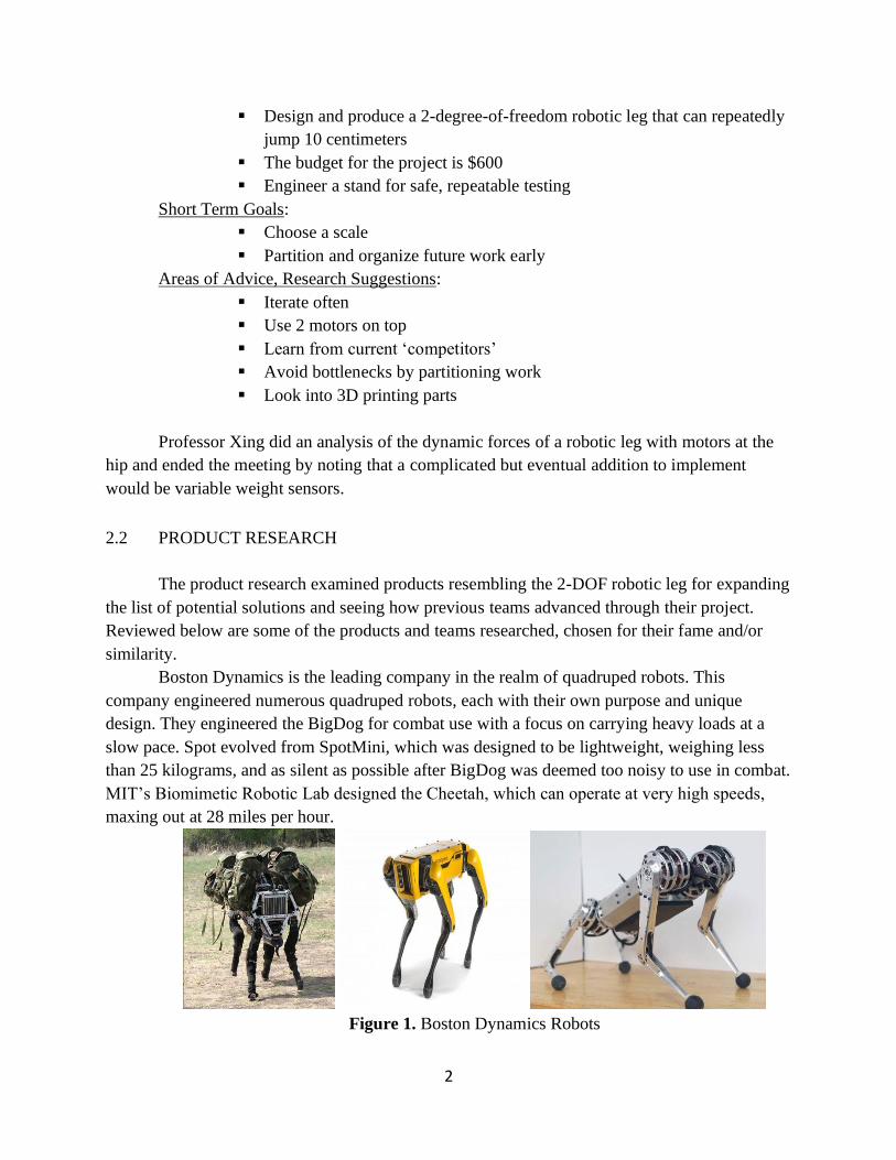
Boston Dynamics is the leading company in the realm of quadruped robots. This
company engineered numerous quadruped robots, each with their own purpose and unique
design. They engineered the BigDog for combat use with a focus on carrying heavy loads at a
slow pace. Spot evolved from SpotMini, which was designed to be lightweight, weighing less
than 25 kilograms, and as silent as possible after BigDog was deemed too noisy to use in combat.
MIT’s Biomimetic Robotic Lab designed the Cheetah, which can operate at very high speeds,
maxing out at 28 miles per hour.
Figure 1. Boston Dynamics Robots
3
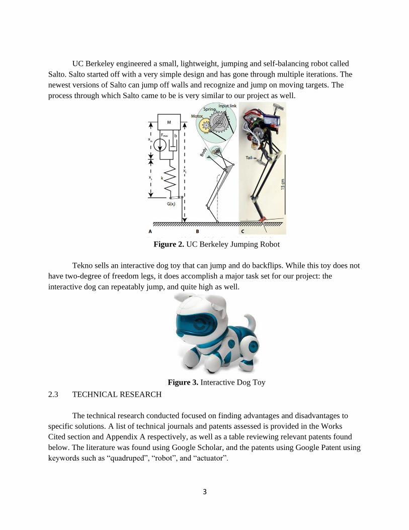
UC Berkeley engineered a small, lightweight, jumping and self-balancing robot called
Salto. Salto started off with a very simple design and has gone through multiple iterations. The
newest versions of Salto can jump off walls and recognize and jump on moving targets. The
process through which Salto came to be is very similar to our project as well.
Figure 2. UC Berkeley Jumping Robot
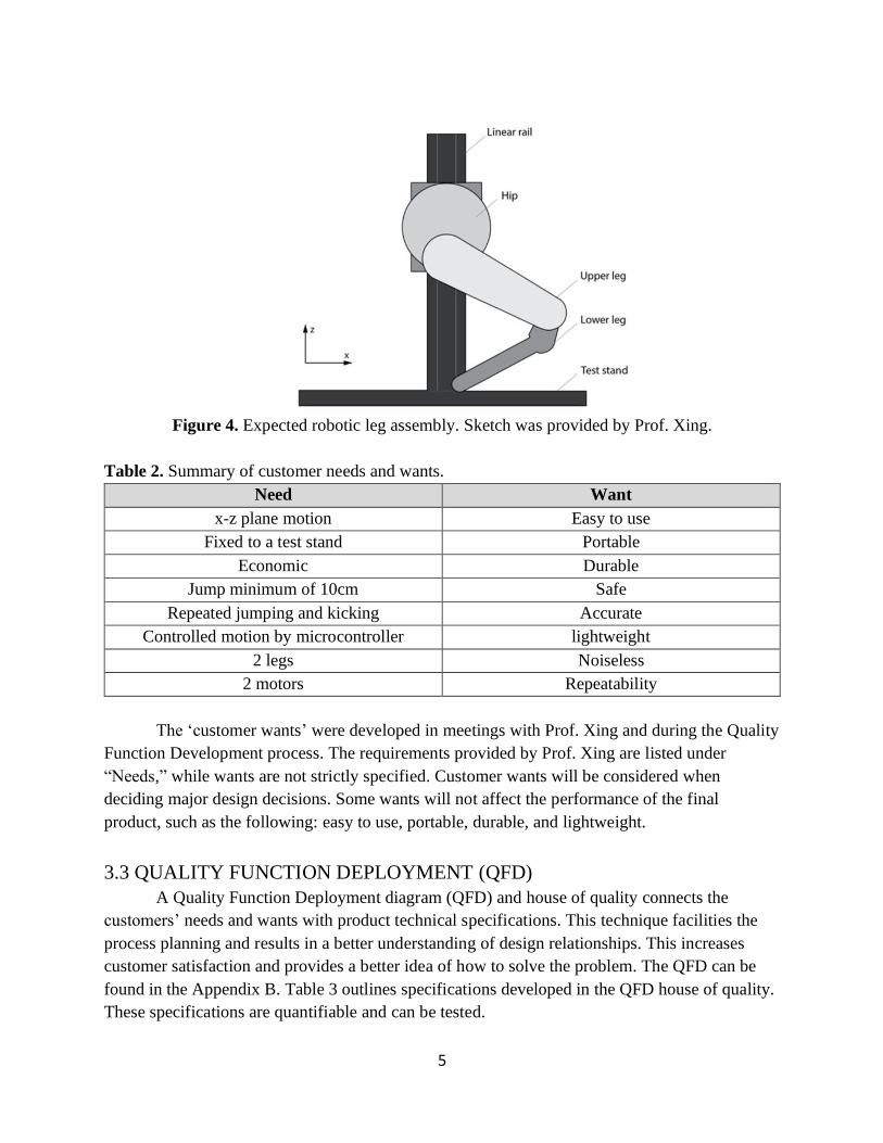
Tekno sells an interactive dog toy that can jump and do backflips. While this toy does not
have two-degree of freedom legs, it does accomplish a major task set for our project: the
interactive dog can repeatably jump, and quite high as well.
Figure 3. Interactive Dog Toy
2.3 TECHNICAL RESEARCH
The technical research conducted focused on finding advantages and disadvantages to
specific solutions. A list of technical journals and patents assessed is provided in the Works
Cited section and Appendix A respectively, as well as a table reviewing relevant patents found
below. The literature was found using Google Scholar, and the patents using Google Patent using
keywords such as “quadruped”, “robot”, and “actuator”.

4
Following the initial sponsor meeting, Professor Xing decided to supply Team Capy with
two joint actuators and their specifications, as seen in Appendix B. With this new information,
the scope of technical research currently remains on motor specifications, simulating equations
of motion, and finding potential materials.
Table 1. Patent List and Useful Qualities
Patent Name Patent Number Main Contributions
A Quadruped Legged Robot
Driven by Linear Actuators
WO200808448
0A1
• Strong claim for linear actuator use
• Similar leg design
Single Leg Mechanism of a
Quadruped Robot CN106627831A
• Use of belt and pulley system
• Description of accurate gear ratio
Single actuator per leg
robotic hexapod US6481513B2
• Unique, simple design
• Better understanding of actuator
capabilities and controls
Walking Mechanism for
Four-Foot Robot Driven and
Controlled by Cams
CN202038387U • Use of DC Servo motor for high
accuracy
Running Robot Having Four
Legs KR101373740B
• Design uses four-bar linkage
• Incorporation of gear-pulley system
3. OBJECTIVES
3.1 PROBLEM STATEMENT
The Cal Poly Mechatronics Department does not have a quadruped robot to use for
research and as a teaching tool. To kickstart this massive project, Professor Xing and the
department have tasked Team Capy with building a 2 Degree of Freedom robotic leg attached to
a stand at the hip. The final product must use two electric motors to accurately jump 10 cm or
more, while costing less than $600.
3.2 CUSTOMER NEEDS & WANTS
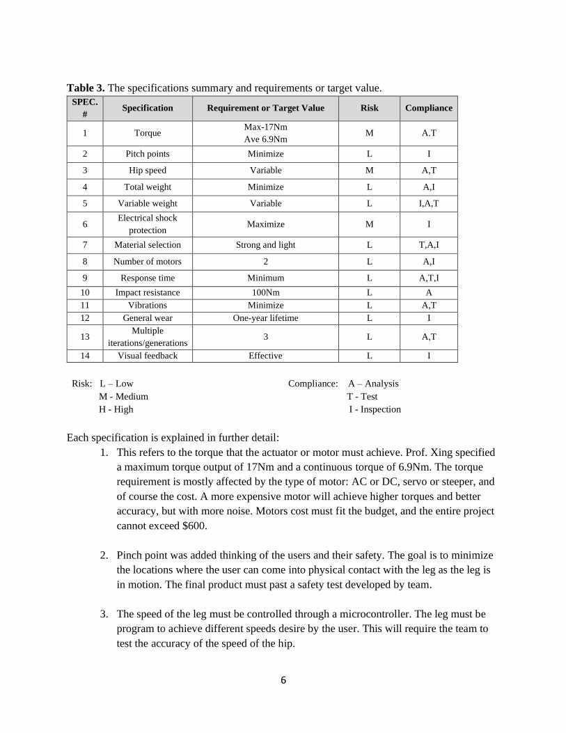
Prof. Xing gave Team Capy the project’s minimum requirements and provided a sketch
of the expected final product (see Figure 2). The leg’s motion will be constrained to the x-z
plane. It will be composed of two actuated joints, each with their own motor, and encoders to
read the angle of each joint. The hip of the leg will be connected to a vertical rail on the test
stand. A microcontroller will control the motors, and consequently the motion of the robot. The
main goal of this robot is to accurately and repeatedly jump 10 cm on command. The leg must be
able to perform several tasks such as kicking and repeated jumping. Table 2 outlines a summary
of the customer needs and wants.
5
Figure 4. Expected robotic leg assembly. Sketch was provided by Prof. Xing.
Table 2. Summary of customer needs and wants.
Need Want
x-z plane motion Easy to use
Fixed to a test stand Portable
Economic Durable
Jump minimum of 10cm Safe
Repeated jumping and kicking Accurate
Controlled motion by microcontroller lightweight
2 legs Noiseless
2 motors Repeatability
The ‘customer wants’ were developed in meetings with Prof. Xing and during the Quality
Function Development process. The requirements provided by Prof. Xing are listed under
“Needs,” while wants are not strictly specified. Customer wants will be considered when
deciding major design decisions. Some wants will not affect the performance of the final
product, such as the following: easy to use, portable, durable, and lightweight.
3.3 QUALITY FUNCTION DEPLOYMENT (QFD)
A Quality Function Deployment diagram (QFD) and house of quality connects the
customers’ needs and wants with product technical specifications. This technique facilities the
process planning and results in a better understanding of design relationships. This increases
customer satisfaction and provides a better idea of how to solve the problem. The QFD can be
found in the Appendix B. Table 3 outlines specifications developed in the QFD house of quality.
These specifications are quantifiable and can be tested.
6
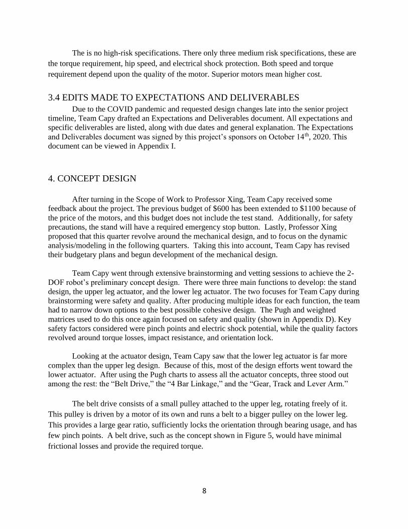
Table 3. The specifications summary and requirements or target value.
SPEC.
# Specification Requirement or Target Value Risk Compliance
1 Torque Max-17Nm
Ave 6.9Nm M A.T
2 Pitch points Minimize L I
3 Hip speed Variable M A,T
4 Total weight Minimize L A,I
5 Variable weight Variable L I,A,T
6 Electrical shock
protection Maximize M I
7 Material selection Strong and light L T,A,I
8 Number of motors 2 L A,I
9 Response time Minimum L A,T,I
10 Impact resistance 100Nm L A
11 Vibrations Minimize L A,T
12 General wear One-year lifetime L I
13 Multiple
iterations/generations 3 L A,T
14 Visual feedback Effective L I
Risk: L – Low
M - Medium
H - High
Compliance: A – Analysis
T - Test
I - Inspection
Each specification is explained in further detail:
1. This refers to the torque that the actuator or motor must achieve. Prof. Xing specified
a maximum torque output of 17Nm and a continuous torque of 6.9Nm. The torque
requirement is mostly affected by the type of motor: AC or DC, servo or steeper, and
of course the cost. A more expensive motor will achieve higher torques and better
accuracy, but with more noise. Motors cost must fit the budget, and the entire project
cannot exceed $600.
2. Pinch point was added thinking of the users and their safety. The goal is to minimize
the locations where the user can come into physical contact with the leg as the leg is
in motion. The final product must past a safety test developed by team.
3. The speed of the leg must be controlled through a microcontroller. The leg must be
program to achieve different speeds desire by the user. This will require the team to
test the accuracy of the speed of the hip.

7
4. The goal is to minimize the total weight of the quadruped leg and test stand. The test
stand should weight more than the leg. This is because during operations the test
stand cannot move as this will affect the balance of the assembly. This allow the
portability of the assembly.
5. There will be a variable weight in the assembly. The goal is to concentrate most of
the weight at the hip leg. The leg material selection will also affect the weight
variations.
6. Since the leg is going to be power electrically, an electrical shock safety protection
must be implemented to the leg. This will improve the overall safe handling of the
device.
7. Since one of the goals is to make the device durable, it therefore must be made of
high strength material. The material must have lightweight because of the weight
considerations. The goal is to optimize the materials.
8. Prof. Xing requested the leg to have two motors. Both located at the hip. This will
play a role in scaling the device.
9. The goal it to minimize the time response of the device. When the user wishes to
execute a motion, the leg must perform effectively to those commands.
10. The assembly should be able to withstand a drop test. This will be performed via
computer software. A 100N force will be applied at the assembly and study the
locations of critical stresses. This location can then be reinforced or redesign for
superior strength.
11. The vibrations created by the motors are ought to be reduce. This will ensure the
durability of the device. To minimize the vibrations the device must operation under
the natural frequency.
12. General gear refers to the wear generated overtime. The goal is to minimize wear by
studying location where there are rough surfaces in contact and heat generated by
frictional contact.
13. Visual feedback is added to allow user to know that the device is safe and ready to
operate with a luminous signal.
8
The is no high-risk specifications. There only three medium risk specifications, these are
the torque requirement, hip speed, and electrical shock protection. Both speed and torque
requirement depend upon the quality of the motor. Superior motors mean higher cost.
3.4 EDITS MADE TO EXPECTATIONS AND DELIVERABLES
Due to the COVID pandemic and requested design changes late into the senior project
timeline, Team Capy drafted an Expectations and Deliverables document. All expectations and
specific deliverables are listed, along with due dates and general explanation. The Expectations
and Deliverables document was signed by this project’s sponsors on October 14th, 2020. This
document can be viewed in Appendix I.
4. CONCEPT DESIGN
After turning in the Scope of Work to Professor Xing, Team Capy received some
feedback about the project. The previous budget of $600 has been extended to $1100 because of
the price of the motors, and this budget does not include the test stand. Additionally, for safety
precautions, the stand will have a required emergency stop button. Lastly, Professor Xing
proposed that this quarter revolve around the mechanical design, and to focus on the dynamic
analysis/modeling in the following quarters. Taking this into account, Team Capy has revised
their budgetary plans and begun development of the mechanical design.
Team Capy went through extensive brainstorming and vetting sessions to achieve the 2-
DOF robot’s preliminary concept design. There were three main functions to develop: the stand
design, the upper leg actuator, and the lower leg actuator. The two focuses for Team Capy during
brainstorming were safety and quality. After producing multiple ideas for each function, the team
had to narrow down options to the best possible cohesive design. The Pugh and weighted
matrices used to do this once again focused on safety and quality (shown in Appendix D). Key
safety factors considered were pinch points and electric shock potential, while the quality factors
revolved around torque losses, impact resistance, and orientation lock.
Looking at the actuator design, Team Capy saw that the lower leg actuator is far more
complex than the upper leg design. Because of this, most of the design efforts went toward the
lower actuator. After using the Pugh charts to assess all the actuator concepts, three stood out
among the rest: the “Belt Drive,” the “4 Bar Linkage,” and the “Gear, Track and Lever Arm.”
The belt drive consists of a small pulley attached to the upper leg, rotating freely of it.
This pulley is driven by a motor of its own and runs a belt to a bigger pulley on the lower leg.
This provides a large gear ratio, sufficiently locks the orientation through bearing usage, and has
few pinch points. A belt drive, such as the concept shown in Figure 5, would have minimal
frictional losses and provide the required torque.

9
Figure 5: Sketch of Belt Drive Lower Leg Actuator
The second-best design was the “4-bar linkage” (see Figure 6). This system involves
having the lower leg motion controlled by a motor that is located at the hip. The motor provides
a torque to the gear that is fixed to bar 1. As bar 1 rotates with a radial velocity, it pushes bar 2 to
move in the radial direction. In consequence, bar 2 applies a torque to bar 4 which pivots around
the joint with bar 3. The torque provided by the motor controls the contraction or expansion of
the legs.
Figure 6: Sketch of 4-Bar Linkage Lower Leg Actuator
This design mainly stands out in material selection, torque required, torque losses, and
orientation lock. The design allows the option to select from many materials such as steel, wood,
and plastic. A minimum amount of torque is required to cause the system to move because of the
minimal torque losses. The design also provides a good orientation lock which is important in
maintaining a controlled jump. This eliminates the need to modify the design to only move in the
XZ motion.

10
The “Gear Track and Lever Arm” is a unique design that was brought forward during the
first brainstorming session. A gear that is spun by the motor is in contact with a track that runs
back and forth as the gear spins. The track is connected at its end to the lower leg knee joint
rotates the lower leg as a lever.
Figure 7: Sketch of Gear Track with Lever Arm Leg Actuator
There are many strengths to this design, including variable design decisions and general
aesthetics. However, the design ultimately lost out because of its lack of safety and inability to
lock orientation. While the gear track connected to a lever arm looks unique, it generates a lot of
pinch points. Team Capy also envisions a difficulty in maintaining contact between the gear and
the track as the actuator is operating.
When focusing on the stand, there were a few key design points that had to be met: the
stand has to allow vertical motion while restricting all other translation and rotation, it must
provide minimal frictional losses, it must be easy to set up, and it must have as few pinch points
as possible. Using the Pugh and weighted matrices to help choose the best design, the top
contenders were “2 Guide Strings in Tension” in 1st place, “Diamond Track with Bearings” in
2nd, and “Pole with Keyway and Cylindrical Slider” in 3rd (as shown in Appendix D).
The “2 Guide Strings in Tension” design allows for the hip to slide vertically along two
tightly wound wires. The two wires negate any unnecessary rotational or translational movement.
The connection between the hip to the wires is crucial as it is a potential source of pinch points
and friction losses. While a definitive design has not been reached, Team Capy has been
11
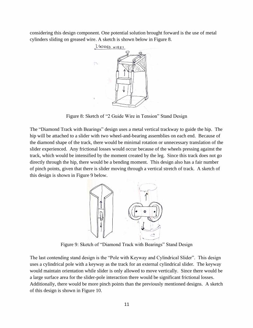
considering this design component. One potential solution brought forward is the use of metal
cylinders sliding on greased wire. A sketch is shown below in Figure 8.
Figure 8: Sketch of “2 Guide Wire in Tension” Stand Design
The “Diamond Track with Bearings” design uses a metal vertical trackway to guide the hip. The
hip will be attached to a slider with two wheel-and-bearing assemblies on each end. Because of
the diamond shape of the track, there would be minimal rotation or unnecessary translation of the
slider experienced. Any frictional losses would occur because of the wheels pressing against the
track, which would be intensified by the moment created by the leg. Since this track does not go
directly through the hip, there would be a bending moment. This design also has a fair number
of pinch points, given that there is slider moving through a vertical stretch of track. A sketch of
this design is shown in Figure 9 below.
Figure 9: Sketch of “Diamond Track with Bearings” Stand Design
The last contending stand design is the “Pole with Keyway and Cylindrical Slider”. This design
uses a cylindrical pole with a keyway as the track for an external cylindrical slider. The keyway
would maintain orientation while slider is only allowed to move vertically. Since there would be
a large surface area for the slider-pole interaction there would be significant frictional losses.
Additionally, there would be more pinch points than the previously mentioned designs. A sketch
of this design is shown in Figure 10.
12
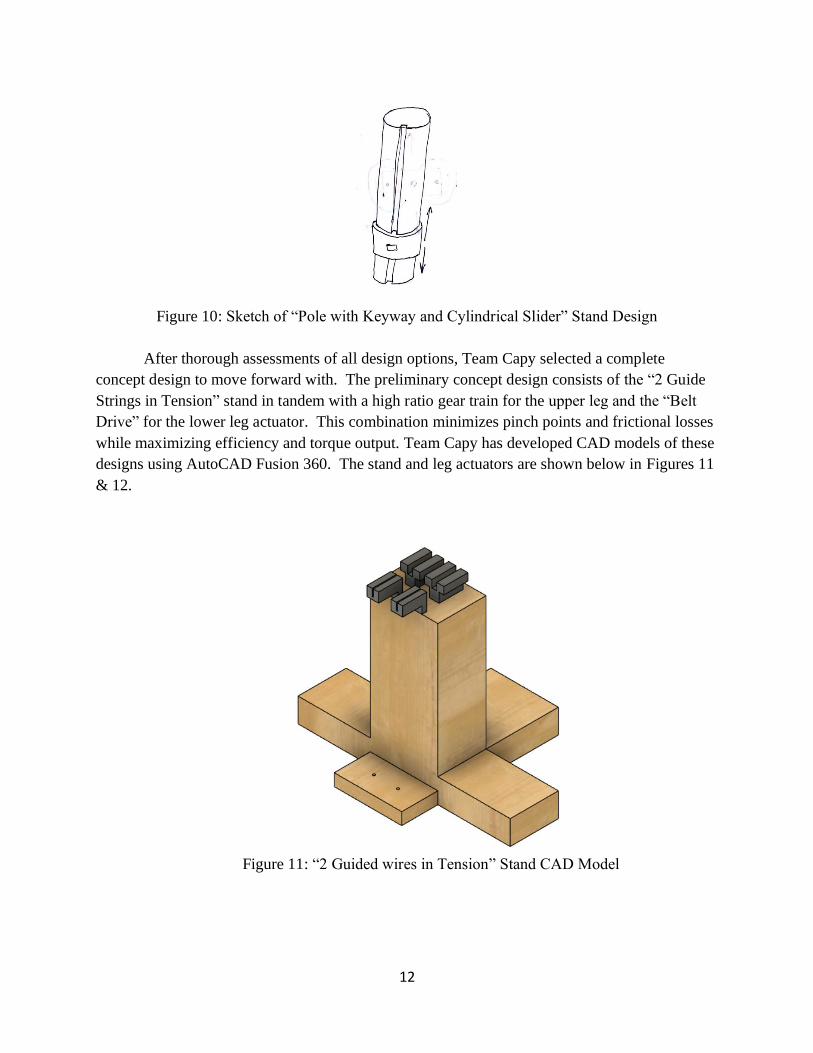
Figure 10: Sketch of “Pole with Keyway and Cylindrical Slider” Stand Design
After thorough assessments of all design options, Team Capy selected a complete
concept design to move forward with. The preliminary concept design consists of the “2 Guide
Strings in Tension” stand in tandem with a high ratio gear train for the upper leg and the “Belt
Drive” for the lower leg actuator. This combination minimizes pinch points and frictional losses
while maximizing efficiency and torque output. Team Capy has developed CAD models of these
designs using AutoCAD Fusion 360. The stand and leg actuators are shown below in Figures 11
& 12.
Figure 11: “2 Guided wires in Tension” Stand CAD Model

13
Figure 12: Fusion Model of Leg Actuators
The stand will mostly be made of wood but use metal connectors to guide and hold the
wires in tension. Not pictured are tightening mechanisms connected to the Y-shaped metal
connectors. Currently Team Capy is thinking of using guitar machine head to tighten the wires.
The leg assembly will be printed with plastic, which is be easy to manufacture using 3D Printing.
Team Capy can use 3D Printing to manufacture the complex geometries of the leg actuators. The
specific plastic has not yet been decided, with more research needed to be performed. Some
considerations in choosing the correct plastic include impact resistance, lifespan, and cost.
Not pictured in the CAD models are the strings of the test stand or a connection to the hip
to allow for guidance from the strings. The connection to the hip for the strings is not a top
priority actively but has been considered by Team Capy. A realistic solution currently brought
forward is a flat plate connected at the top of the hip with holes for the guide strings. A potential
addition to the scope of the project enabled by this design is the addition of variable weight. With
a flat top and guide strings, weighted circular disks can be stacked on top of the hip. This
addition would be exciting but would the largely affect the computational simulation.
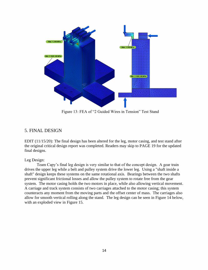
Shown below in Figure 13 are two captures of the chosen test stand design during a
simulated static stress analysis. The study materials were edited such that the lower body has
properties similar to pine wood, and the bodies attached at the top have the properties of steel.
Contacts were automatically generated as well as a three-way constraint applied to the bottom
face. The load arrows seen are all equal to 20 Newtons and represent points where the string
applies most stress to the stand.
14
Figure 13: FEA of “2 Guided Wires in Tension” Test Stand
5. FINAL DESIGN
EDIT (11/15/20): The final design has been altered for the leg, motor casing, and test stand after
the original critical design report was completed. Readers may skip to PAGE 19 for the updated
final designs.
Leg Design:
Team Capy’s final leg design is very similar to that of the concept design. A gear train
drives the upper leg while a belt and pulley system drive the lower leg. Using a "shaft inside a
shaft" design keeps these systems on the same rotational axis. Bearings between the two shafts
prevent significant frictional losses and allow the pulley system to rotate free from the gear
system. The motor casing holds the two motors in place, while also allowing vertical movement.
A carriage and track system consists of two carriages attached to the motor casing; this system
counteracts any moment from the moving parts and the offset center of mass. The carriages also
allow for smooth vertical rolling along the stand. The leg design can be seen in Figure 14 below,
with an exploded view in Figure 15.

15
Figure 14: Robot Leg Final Design
Figure 15: Exploded view Robotic Leg

16
The significant changes from the concept design are the gear/pulley ratios, the type of pulleys,
and the motor casing. After analyzing the pulley setup and the torque output, Team Capy
decided to optimize the pulleys to maximize rotational velocity instead of maximizing the torque.
The motors have a very high torque output relative to the weight of the system, and our target is
hip speed. Hip speed is more important than torque output because the hip needs to reach a
critical velocity to jump the desired height. Team Capy settled on a gear ratio of 1.5 for both the
pulleys and the gears. Additionally, Team Capy switched from a flat belt drive setup to a timing
belt system. Timing belts use teethed belts to reduce friction, allow for more effective direction
changing, and prevent slippage in high-stress applications. The concept design had not yet
finalized a motor casing design. The final motor casing supports both motors while allowing
unrestricted movement along only the vertical axis. This stand design and setup restrict all other
five degrees of freedom.
Stand Design:
Since finishing the test stand concept design, Team Capy has implemented changes into
the final design. After a design change request by the sponsor, the new test stand is now designed
to guide the hip via guide rails. These guide rails are mounted on square steel tubing that makes
up the frame, as seen below in Figure 15. The implemented changes from a wooden stand to a
steel frame exist for two reasons. Primarily, amidst the current pandemic (COVID-19), it is
advised that Team Capy pre-purchase as many materials as possible, as discussed further in the
next section. Also, the guide rails must be parallel to one another, which will be much easier to
Figure 16. Updated Test Stand CAD
17
Team Capy did not decide on guide rails for the first concept design, nor were guide rails
the first solution after being asked to implement a vertical slider attachment. Initially, Team
Capy investigated camera sliders as an option for a vertical slider mechanism. The sliders have
minimal friction and can carry an impressive load. What the camera sliders lacked was the
capability to attach a non-camera object. Ultimately, Team Capy chose to use guide rails because
there would be fewer moving parts and easier, more secure attachment to the carriages.
Not pictured is a secure holding for a power source. Team Capy has received
specifications of a current power source that may be used. Since the primary scope of the project
remains mechanical design, the securing of the power source will be done after the completion of
a mechanical product.
Safety:
There are many moving parts in this assembly, so safety is a big concern. Team Capy
decided to encase the entire robotic leg and test stand in an acrylic box. This will allow users to
see the functioning robot but not be able to touch it during operation. The system will be wired
so that this box must be in place for the system to run. This simple solution takes care of all
possible mechanical injuries.
As for maintenance, the only foreseeable areas to look at are belt wear and bearing
friction. These main sources of error come from many cycles of usage under high stress, and
external factors such as dirt, etc.. The timing belt we chose has steel cords reinforcing it to
provide both short and long-term strength so the belt does not stretch. The source of wear here is
the teeth on the belt. After many stressful cycles, these will wear and introduce slippage to the
system. The bearings we chose are sealed ball bearings, so they retain their grease and block dirt
from entering the system. Although these are a long-term solution, they should also be oiled to
remain as friction free as possible.
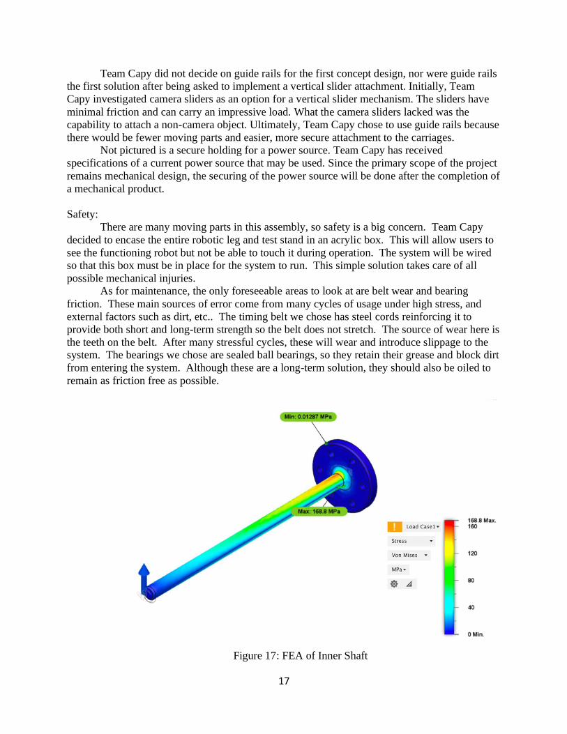
Figure 17: FEA of Inner Shaft

18
Figure 18: FEA of Lower Leg
Figures 17 & 18 show the Finite Element Analysis of the Inner shaft and lower leg. The
lower leg is very thick and is no danger of plastically deforming. The inner shaft, however, is
fairly thin and experiences a lot of stress relative to its size. After doing this analysis, Team
Capy has decided to reduce the load on the inner shaft by reducing the weight of the legs. We
will do this by strategically cutting sections out of the upper and inner leg so it would retain its
structural integrity while being a much lighter component. Due to COVID-19 complications,
machining the sections on the leg must be delayed.
Attached as Appendix H is the FMEA chart Team Capy created before the PDR. While
the design of the legs and test stand changed a few times, with new components added, Team
Capy notes that the core functionality of the project never veered off course, in part by
understanding the potential areas for failure early on.
The bill of materials is attached as two Excel sheets Appendix I; the first regarding parts
for the hip and leg assemblies, the second for the test stand. In total there are over 230 individual
parts, roughly 200 of which assemble the test stand. Noticeably, the test stand is much more
expensive than than the leg and hip assembly, ≈$2500 and $500 respectively. There are two main
reasons why the test stand design is so expensive. First, expensive parts such as the guide rails
and carriages are sourced from McMaster-Carr for their high quality. Our sponsor Professor
Xing expressed interest in experiencing minimal mechanical friction. The second reason is that
the test stand assembly also lists money for an encoder and pressure pad. While $750 is set aside
for these two measuring devices, they are not the primary focus of the scope of the project and
will be added after the mechanical product is fully functional.
EDIT: 11/18/20
The final leg design evolved over summer to further reduce weight, reduce part count, add a belt
tensioning mechanism, and prepare for simpler fabrication and assembly due to the COVID 19
pandemic. A few key changes occurred: a switch from aluminum to polycarbonate for the leg,
the addition of lightning holes to, the use of smaller composite pulleys, and the addition of a
19
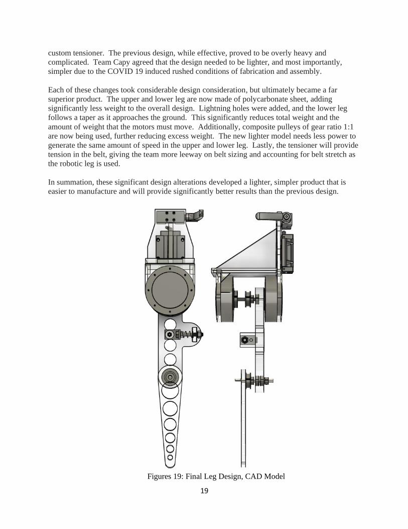
custom tensioner. The previous design, while effective, proved to be overly heavy and
complicated. Team Capy agreed that the design needed to be lighter, and most importantly,
simpler due to the COVID 19 induced rushed conditions of fabrication and assembly.
Each of these changes took considerable design consideration, but ultimately became a far
superior product. The upper and lower leg are now made of polycarbonate sheet, adding
significantly less weight to the overall design. Lightning holes were added, and the lower leg
follows a taper as it approaches the ground. This significantly reduces total weight and the
amount of weight that the motors must move. Additionally, composite pulleys of gear ratio 1:1
are now being used, further reducing excess weight. The new lighter model needs less power to
generate the same amount of speed in the upper and lower leg. Lastly, the tensioner will provide
tension in the belt, giving the team more leeway on belt sizing and accounting for belt stretch as
the robotic leg is used.
In summation, these significant design alterations developed a lighter, simpler product that is
easier to manufacture and will provide significantly better results than the previous design.
Figures 19: Final Leg Design, CAD Model
20
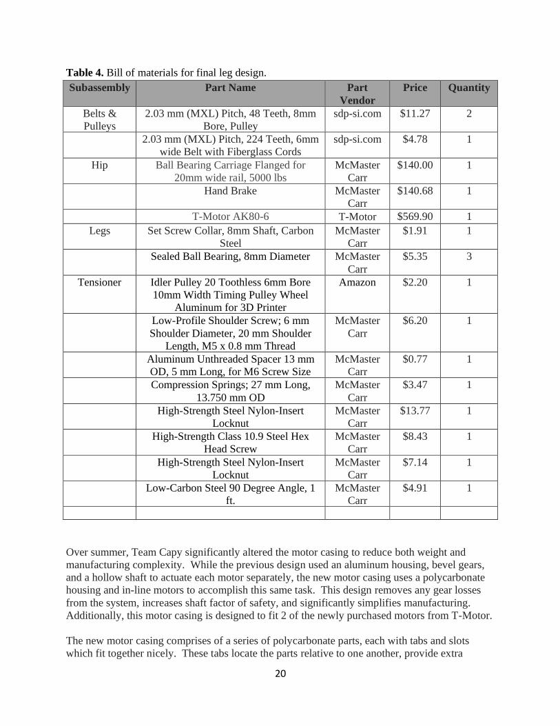
Table 4. Bill of materials for final leg design.
Subassembly Part Name Part
Vendor
Price Quantity
Belts &
Pulleys
2.03 mm (MXL) Pitch, 48 Teeth, 8mm
Bore, Pulley
sdp-si.com $11.27 2
2.03 mm (MXL) Pitch, 224 Teeth, 6mm
wide Belt with Fiberglass Cords
sdp-si.com $4.78 1
Hip Ball Bearing Carriage Flanged for
20mm wide rail, 5000 lbs
McMaster
Carr
$140.00 1
Hand Brake McMaster
Carr
$140.68 1
T-Motor AK80-6 T-Motor $569.90 1
Legs Set Screw Collar, 8mm Shaft, Carbon
Steel
McMaster
Carr
$1.91 1
Sealed Ball Bearing, 8mm Diameter McMaster
Carr
$5.35 3
Tensioner Idler Pulley 20 Toothless 6mm Bore
10mm Width Timing Pulley Wheel
Aluminum for 3D Printer
Amazon $2.20 1
Low-Profile Shoulder Screw; 6 mm
Shoulder Diameter, 20 mm Shoulder
Length, M5 x 0.8 mm Thread
McMaster
Carr
$6.20 1
Aluminum Unthreaded Spacer 13 mm
OD, 5 mm Long, for M6 Screw Size
McMaster
Carr
$0.77 1
Compression Springs; 27 mm Long,
13.750 mm OD
McMaster
Carr
$3.47 1
High-Strength Steel Nylon-Insert
Locknut
McMaster
Carr
$13.77 1
High-Strength Class 10.9 Steel Hex
Head Screw
McMaster
Carr
$8.43 1
High-Strength Steel Nylon-Insert
Locknut
McMaster
Carr
$7.14 1
Low-Carbon Steel 90 Degree Angle, 1
ft.
McMaster
Carr
$4.91 1
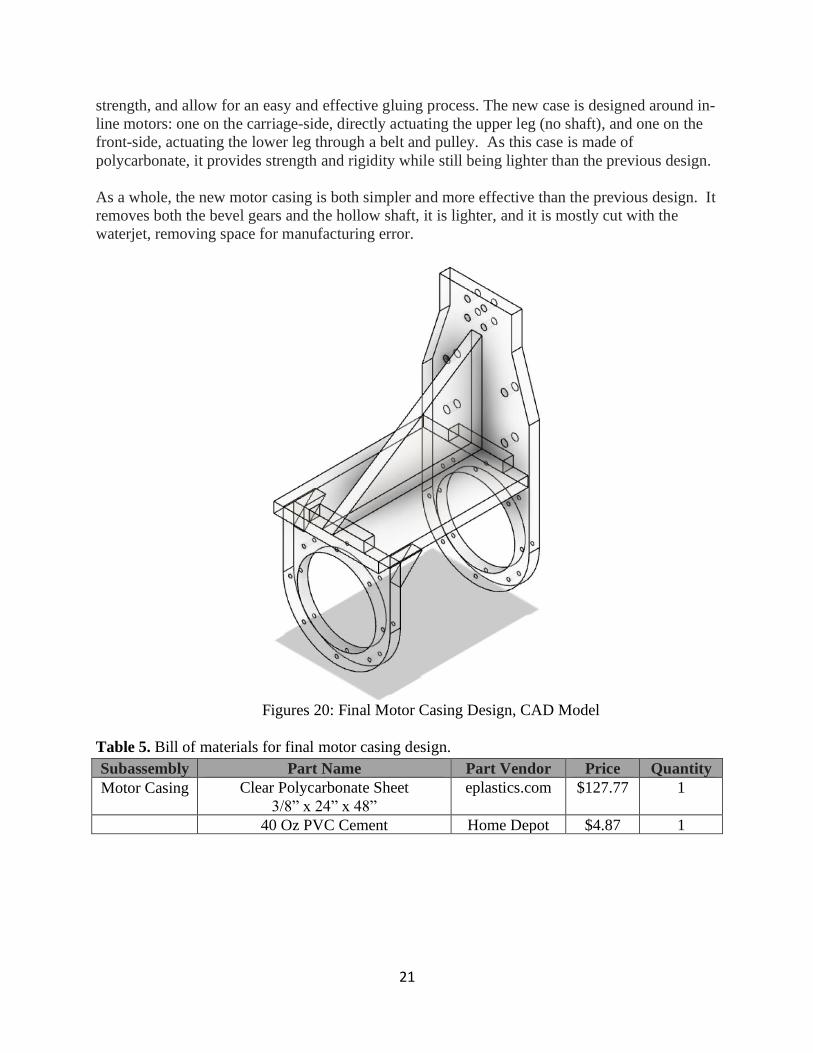
Over summer, Team Capy significantly altered the motor casing to reduce both weight and
manufacturing complexity. While the previous design used an aluminum housing, bevel gears,
and a hollow shaft to actuate each motor separately, the new motor casing uses a polycarbonate
housing and in-line motors to accomplish this same task. This design removes any gear losses
from the system, increases shaft factor of safety, and significantly simplifies manufacturing.
Additionally, this motor casing is designed to fit 2 of the newly purchased motors from T-Motor.
The new motor casing comprises of a series of polycarbonate parts, each with tabs and slots
which fit together nicely. These tabs locate the parts relative to one another, provide extra
21
strength, and allow for an easy and effective gluing process. The new case is designed around in-
line motors: one on the carriage-side, directly actuating the upper leg (no shaft), and one on the
front-side, actuating the lower leg through a belt and pulley. As this case is made of
polycarbonate, it provides strength and rigidity while still being lighter than the previous design.
As a whole, the new motor casing is both simpler and more effective than the previous design. It
removes both the bevel gears and the hollow shaft, it is lighter, and it is mostly cut with the
waterjet, removing space for manufacturing error.
Figures 20: Final Motor Casing Design, CAD Model
Table 5. Bill of materials for final motor casing design.
Subassembly Part Name Part Vendor Price Quantity
Motor Casing Clear Polycarbonate Sheet
3/8” x 24” x 48”
eplastics.com $127.77 1
40 Oz PVC Cement Home Depot $4.87 1
22
Final Test Stand Design:
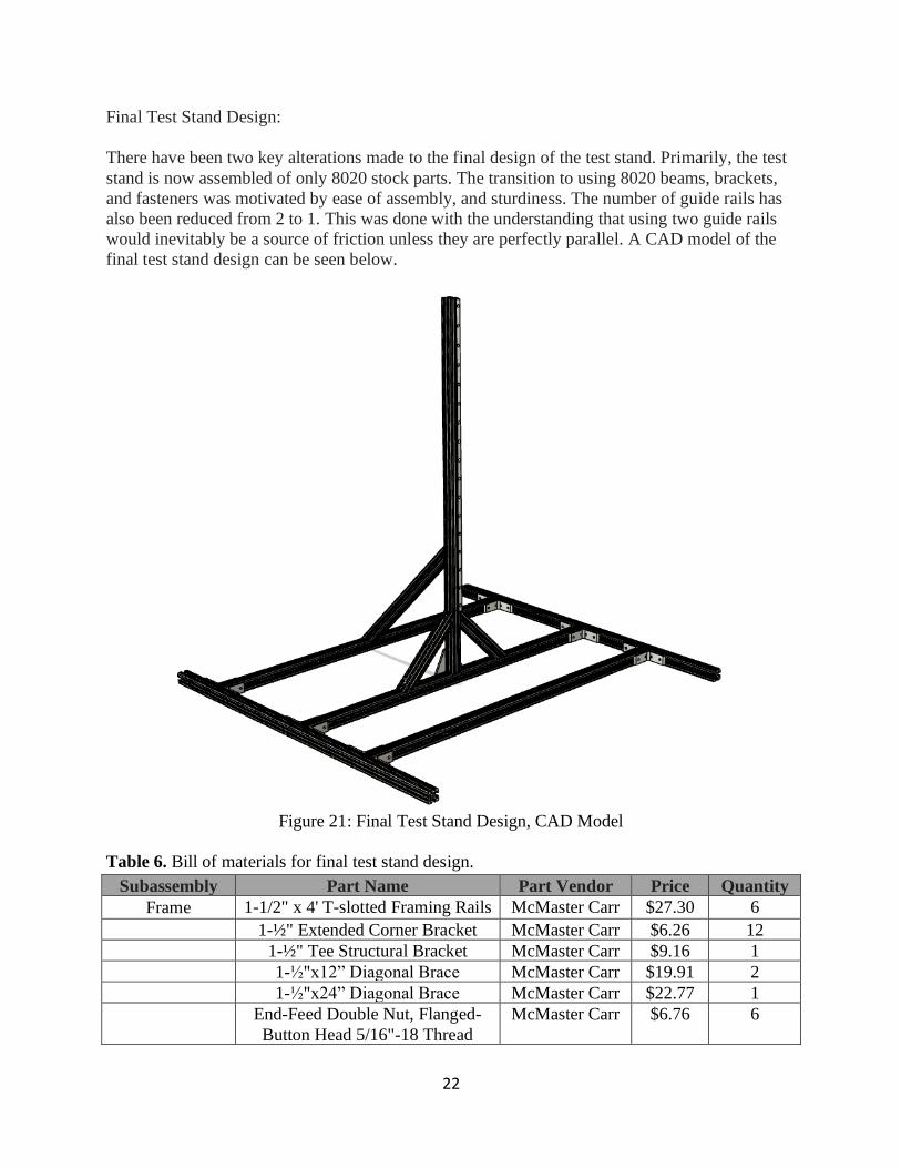
There have been two key alterations made to the final design of the test stand. Primarily, the test
stand is now assembled of only 8020 stock parts. The transition to using 8020 beams, brackets,
and fasteners was motivated by ease of assembly, and sturdiness. The number of guide rails has
also been reduced from 2 to 1. This was done with the understanding that using two guide rails
would inevitably be a source of friction unless they are perfectly parallel. A CAD model of the
final test stand design can be seen below.
Figure 21: Final Test Stand Design, CAD Model
Table 6. Bill of materials for final test stand design.
Subassembly Part Name Part Vendor Price Quantity
Frame 1-1/2" x 4' T-slotted Framing Rails McMaster Carr $27.30 6
1-½" Extended Corner Bracket McMaster Carr $6.26 12
1-½" Tee Structural Bracket McMaster Carr $9.16 1
1-½"x12” Diagonal Brace McMaster Carr $19.91 2
1-½"x24” Diagonal Brace McMaster Carr $22.77 1
End-Feed Double Nut, Flanged-
Button Head 5/16"-18 Thread
McMaster Carr $6.76 6

23
Carriage Guide Guide Rail, 20mm wide McMaster Carr $400 1
M6-1.0 x 18mm Socket Head Cap
Screws Metric
McMaster Carr $8.49 1
T-Slotted Framing, End-Feed
Single Nut, M6 Thread, for 30 mm
Single Rail
McMaster Carr $8.06 1
Final Resources Design:
Along with the physical deliverable, Team Capy is also handing over some virtual resources and
files. For CAD and drawings, Autodesk Fusion 360 was used. Team Capy will be sharing the
following folders: “Final Files”, “Subcomponents”, “Non-Final Files”, and “DXF Files”.
• The “Final Files” folder will be all the final models and drawings pertaining to the 2DoF
robotic leg. That includes the models and drawings for the final leg, motor casing, and
test stand design.
• The “Subcomponents” folder holds all the models for subcomponents used for the leg
design; motors, timing belt, ball bearing. (Nested within “Final Files”)
• The “Non-Final Files” folder contains all the models, drawings, and all rough drafts done
on Fusion leading up to the final models.
• The “DXF files” are used for cutting parts on the waterjet. The drawings are of the legs,
the motor casing parts, and the shaft base.
6. MANUFACTURING PLAN
Approaching the end of Spring quarter and Summer months, it became abundantly clear
that the COVID pandemic was here to stay for the time being. As such, Team Capy made above
the changes to the design with hopes of decreasing fabrication requirements. Following the
fabrication section of the manufacturing plan all assembly procedures are listed. Before each
procedure there are lists depicting the tools, materials, safety measures, and equipment necessary
to advance.
6.1 FABRICATION
Team Capy opted for a design that requires very little fabrication and mostly assembly.
Most of the fabrication revolve around the leg and casing. The stand had no fabrication except of
the landing pad. The leg subcomponents that required fabrication are the tensioner, upper leg
motor shaft and lower leg shaft connector. All other leg and motor casing components were cut
and assemble. The following lists tools required, raw material used, especial equipment needed,
and fabrication procedure.
Leg:
24
For the leg fabrication the following tools and equipment were crucial for fabricating the leg
components.
Tools list:
Waterjet, MIG welder machine, circular saw, Bridgepoint mill, chop saw, router, drill press, vise,
clamps, grinder, metric drill bits, sandpaper, PVC cement and measuring stick.
Raw Material:
90° angle steel bar, Polycarbonate sheet, M8 steel rod.
Equipment list:
Wear appropriate clothing, safety glasses, earmuffs, face shield, appropriate welding gadgets and
gear.
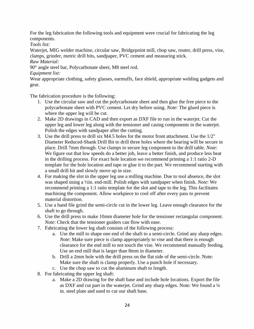
The fabrication procedure is the following:
1. Use the circular saw and cut the polycarbonate sheet and then glue the free piece to the
polycarbonate sheet with PVC cement. Let dry before using. Note: The glued piece is
where the upper leg will be cut.
2. Make 2D drawings in CAD and then export as DXF file to run in the waterjet. Cut the
upper leg and lower leg along with the tensioner and casing components in the waterjet.
Polish the edges with sandpaper after the cutting.
3. Use the drill press to drill six M4.5 holes for the motor front attachment. Use the 1/2"
Diameter Reduced-Shank Drill Bit to drill three holes where the bearing will be secure in
place. Drill 7mm through. Use clamps to secure leg component to the drill table. Note:
We figure out that low speeds do a better job, leave a better finish, and produce less heat
in the drilling process. For exact hole location we recommend printing a 1:1 ratio 2-D
template for the hole location and tape or glue it to the part. We recommend starting with
a small drill bit and slowly move up in size.
4. For making the slot in the upper leg use a milling machine. Due to tool absence, the slot
was shaped using a ½in. end-mill. Polish edges with sandpaper when finish. Note: We
recommend printing a 1:1 ratio template for the slot and tape to the leg. This facilitates
machining the component. Allow workpiece to cool off after every pass to prevent
material distortion.
5. Use a hand file grind the semi-circle cut in the lower leg. Leave enough clearance for the
shaft to go through.
6. Use the drill press to make 10mm diameter hole for the tensioner rectangular component.
Note: Check that the tensioner guiders can flow with ease.
7. Fabricating the lower leg shaft consists of the following process:
a. Use the mill to shape one end of the shaft to a semi-circle. Grind any sharp edges.
Note: Make sure piece is clamp appropriately to vise and that there is enough
clearance for the end mill to not touch the vise. We recommend manually feeding.
Use an end mill that is larger than 8mm in diameter.
b. Drill a 2mm hole with the drill press on the flat side of the semi-circle. Note:
Make sure the shaft is clamp properly. Use a punch hole if necessary.
c. Use the chop saw to cut the aluminum shaft to length.
8. For fabricating the upper leg shaft:
a. Make a 2D drawing for the shaft base and include hole locations. Export the file
as DXF and cut part in the waterjet. Grind any sharp edges. Note: We found a ¼
in. steel plate and used to cut our shaft base.
25
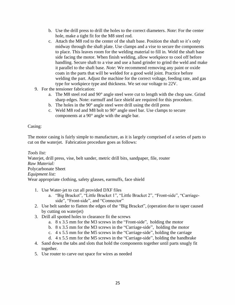
b. Use the drill press to drill the holes to the correct diameters. Note: For the center
hole, make a tight fit for the M8 steel rod.
c. Attach the M8 rod to the center of the shaft base. Position the shaft so it’s only
midway through the shaft plate. Use clamps and a vise to secure the components
to place. This leaves room for the welding material to fill in. Weld the shaft base
side facing the motor. When finish welding, allow workpiece to cool off before
handling. Secure shaft to a vise and use a hand grinder to grind the weld and make
it parallel to the shaft base. Note: We recommend removing any paint or oxide
coats in the parts that will be welded for a good weld joint. Practice before
welding the part. Adjust the machine for the correct voltage, feeding rate, and gas
type for workpiece type and thickness. We set our voltage to 22V.
9. For the tensioner fabrication:
a. The M8 steel rod and 90° angle steel were cut to length with the chop saw. Grind
sharp edges. Note: earmuff and face shield are required for this procedure.
b. The holes in the 90° angle steel were drill using the drill press
c. Weld M8 rod and M8 bolt to 90° angle steel bar. Use clamps to secure
components at a 90° angle with the angle bar.
Casing:
The motor casing is fairly simple to manufacture, as it is largely comprised of a series of parts to
cut on the waterjet. Fabrication procedure goes as follows:
Tools list:
Waterjet, drill press, vise, belt sander, metric drill bits, sandpaper, file, router
Raw Material:
Polycarbonate Sheet
Equipment list:
Wear appropriate clothing, safety glasses, earmuffs, face shield
1. Use Water-jet to cut all provided DXF files
a. “Big Bracket”, “Little Bracket 1”, “Little Bracket 2”, “Front-side”, “Carriage-
side”, “Front-side”, and “Connector”
2. Use belt sander to flatten the edges of the “Big Bracket”, (operation due to taper caused
by cutting on waterjet)
3. Drill all spotted holes to clearance fit the screws
a. 8 x 3.5 mm for the M3 screws in the “Front-side”, holding the motor
b. 8 x 3.5 mm for the M3 screws in the “Carriage-side”, holding the motor
c. 4 x 5.5 mm for the M5 screws in the “Carriage-side”, holding the carriage
d. 4 x 5.5 mm for the M5 screws in the “Carriage-side”, holding the handbrake
4. Sand down the tabs and slots that hold the components together until parts snugly fit
together.
5. Use router to carve out space for wires as needed
26
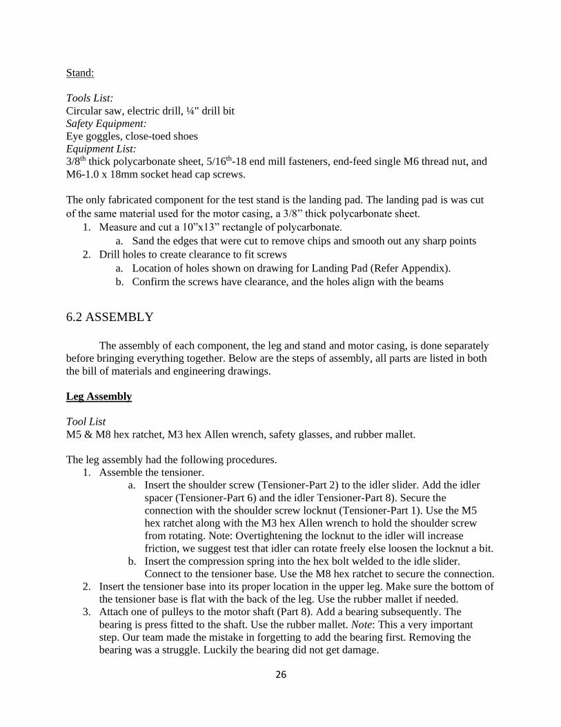
Stand:
Tools List:
Circular saw, electric drill, ¼" drill bit
Safety Equipment:
Eye goggles, close-toed shoes
Equipment List:
3/8th thick polycarbonate sheet, 5/16th-18 end mill fasteners, end-feed single M6 thread nut, and
M6-1.0 x 18mm socket head cap screws.
The only fabricated component for the test stand is the landing pad. The landing pad is was cut
of the same material used for the motor casing, a 3/8” thick polycarbonate sheet.
1. Measure and cut a 10”x13” rectangle of polycarbonate.
a. Sand the edges that were cut to remove chips and smooth out any sharp points
2. Drill holes to create clearance to fit screws
a. Location of holes shown on drawing for Landing Pad (Refer Appendix).
b. Confirm the screws have clearance, and the holes align with the beams
6.2 ASSEMBLY
The assembly of each component, the leg and stand and motor casing, is done separately
before bringing everything together. Below are the steps of assembly, all parts are listed in both
the bill of materials and engineering drawings.
Leg Assembly
Tool List
M5 & M8 hex ratchet, M3 hex Allen wrench, safety glasses, and rubber mallet.
The leg assembly had the following procedures.
1. Assemble the tensioner.
a. Insert the shoulder screw (Tensioner-Part 2) to the idler slider. Add the idler
spacer (Tensioner-Part 6) and the idler Tensioner-Part 8). Secure the
connection with the shoulder screw locknut (Tensioner-Part 1). Use the M5
hex ratchet along with the M3 hex Allen wrench to hold the shoulder screw
from rotating. Note: Overtightening the locknut to the idler will increase
friction, we suggest test that idler can rotate freely else loosen the locknut a bit.
b. Insert the compression spring into the hex bolt welded to the idle slider.
Connect to the tensioner base. Use the M8 hex ratchet to secure the connection.
2. Insert the tensioner base into its proper location in the upper leg. Make sure the bottom of
the tensioner base is flat with the back of the leg. Use the rubber mallet if needed.
3. Attach one of pulleys to the motor shaft (Part 8). Add a bearing subsequently. The
bearing is press fitted to the shaft. Use the rubber mallet. Note: This a very important
step. Our team made the mistake in forgetting to add the bearing first. Removing the
bearing was a struggle. Luckily the bearing did not get damage.
27
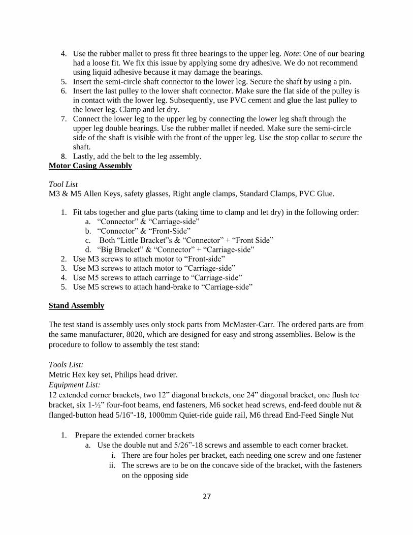
4. Use the rubber mallet to press fit three bearings to the upper leg. Note: One of our bearing
had a loose fit. We fix this issue by applying some dry adhesive. We do not recommend
using liquid adhesive because it may damage the bearings.
5. Insert the semi-circle shaft connector to the lower leg. Secure the shaft by using a pin.
6. Insert the last pulley to the lower shaft connector. Make sure the flat side of the pulley is
in contact with the lower leg. Subsequently, use PVC cement and glue the last pulley to
the lower leg. Clamp and let dry.
7. Connect the lower leg to the upper leg by connecting the lower leg shaft through the
upper leg double bearings. Use the rubber mallet if needed. Make sure the semi-circle
side of the shaft is visible with the front of the upper leg. Use the stop collar to secure the
shaft.
8. Lastly, add the belt to the leg assembly. Motor Casing Assembly
Tool List
M3 & M5 Allen Keys, safety glasses, Right angle clamps, Standard Clamps, PVC Glue.
1. Fit tabs together and glue parts (taking time to clamp and let dry) in the following order:
a. “Connector” & “Carriage-side”
b. “Connector” & “Front-Side”
c. Both “Little Bracket”s & “Connector” + “Front Side”
d. “Big Bracket” & “Connector” + “Carriage-side”
2. Use M3 screws to attach motor to “Front-side”
3. Use M3 screws to attach motor to “Carriage-side”
4. Use M5 screws to attach carriage to “Carriage-side”
5. Use M5 screws to attach hand-brake to “Carriage-side”
Stand Assembly
The test stand is assembly uses only stock parts from McMaster-Carr. The ordered parts are from
the same manufacturer, 8020, which are designed for easy and strong assemblies. Below is the
procedure to follow to assembly the test stand:
Tools List:
Metric Hex key set, Philips head driver.
Equipment List:
12 extended corner brackets, two 12” diagonal brackets, one 24” diagonal bracket, one flush tee
bracket, six 1-½” four-foot beams, end fasteners, M6 socket head screws, end-feed double nut &
flanged-button head 5/16"-18, 1000mm Quiet-ride guide rail, M6 thread End-Feed Single Nut
1. Prepare the extended corner brackets
a. Use the double nut and 5/26”-18 screws and assemble to each corner bracket.
i. There are four holes per bracket, each needing one screw and one fastener
ii. The screws are to be on the concave side of the bracket, with the fasteners
on the opposing side
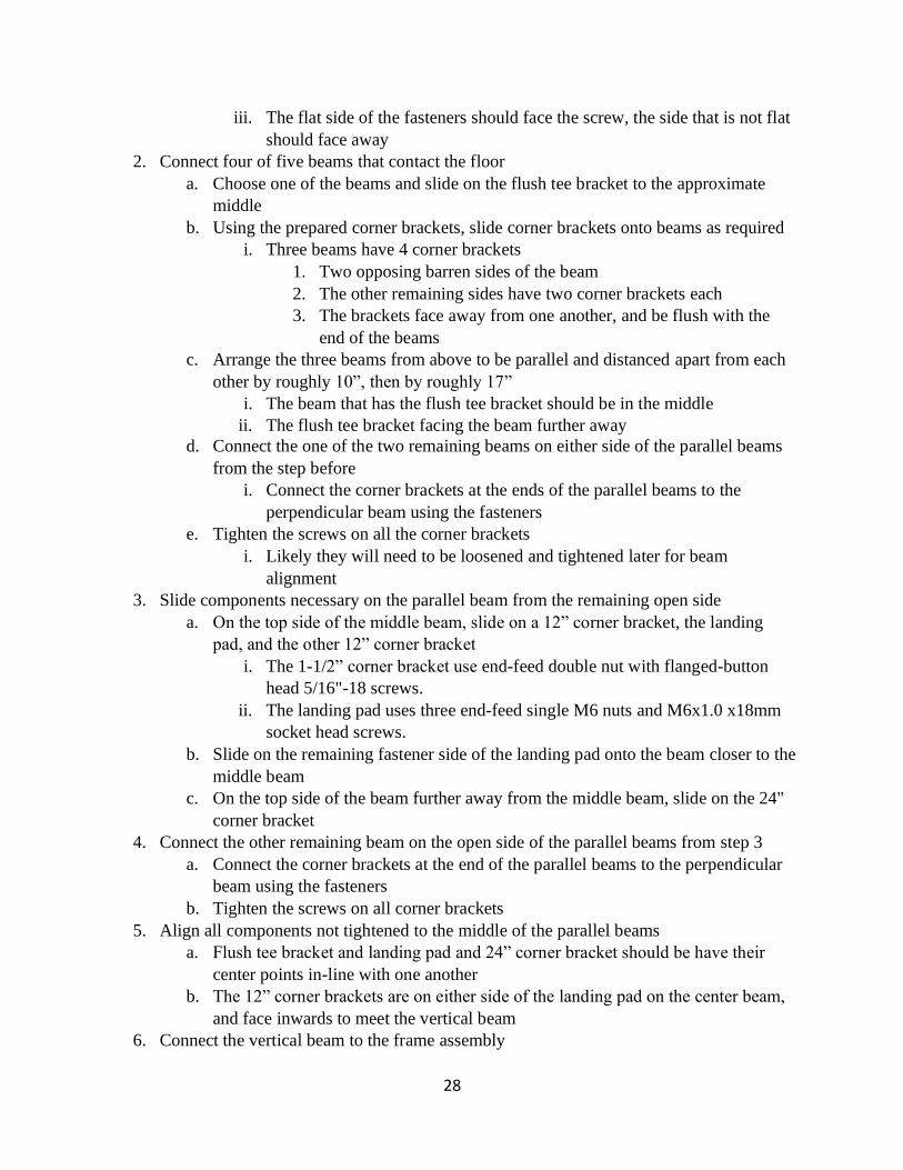
28
iii. The flat side of the fasteners should face the screw, the side that is not flat
should face away
2. Connect four of five beams that contact the floor
a. Choose one of the beams and slide on the flush tee bracket to the approximate
middle
b. Using the prepared corner brackets, slide corner brackets onto beams as required
i. Three beams have 4 corner brackets
1. Two opposing barren sides of the beam
2. The other remaining sides have two corner brackets each
3. The brackets face away from one another, and be flush with the
end of the beams
c. Arrange the three beams from above to be parallel and distanced apart from each
other by roughly 10”, then by roughly 17”
i. The beam that has the flush tee bracket should be in the middle
ii. The flush tee bracket facing the beam further away
d. Connect the one of the two remaining beams on either side of the parallel beams
from the step before
i. Connect the corner brackets at the ends of the parallel beams to the
perpendicular beam using the fasteners
e. Tighten the screws on all the corner brackets
i. Likely they will need to be loosened and tightened later for beam
alignment
3. Slide components necessary on the parallel beam from the remaining open side
a. On the top side of the middle beam, slide on a 12” corner bracket, the landing
pad, and the other 12” corner bracket
i. The 1-1/2” corner bracket use end-feed double nut with flanged-button
head 5/16"-18 screws.
ii. The landing pad uses three end-feed single M6 nuts and M6x1.0 x18mm
socket head screws.
b. Slide on the remaining fastener side of the landing pad onto the beam closer to the
middle beam
c. On the top side of the beam further away from the middle beam, slide on the 24"
corner bracket
4. Connect the other remaining beam on the open side of the parallel beams from step 3
a. Connect the corner brackets at the end of the parallel beams to the perpendicular
beam using the fasteners
b. Tighten the screws on all corner brackets
5. Align all components not tightened to the middle of the parallel beams
a. Flush tee bracket and landing pad and 24” corner bracket should be have their
center points in-line with one another
b. The 12” corner brackets are on either side of the landing pad on the center beam,
and face inwards to meet the vertical beam
6. Connect the vertical beam to the frame assembly

29
a. Align the vertical beam where all the components from the step before set
b. Slide the vertical beam to be connected to all the components listed, eventually
resting on top of the landing pad
i. First slide in the fasteners for the 24” corner bracket
ii. Then slide in the fasteners on either side for the 12” corner bracket
iii. Lastly slide the vertical beam to be connected to the flush tee bracket
c. Tighten all the connections to the vertical beam, and on stand
i. You may need to loosen and re-tighten a few times to ensure
perpendicular alignment at corners
7. Connect the guide rail to the vertical beam
a. Prepare the guide rail for attachment by connecting M6x1.0 x 18mm socket head
screws with end-feed single M6 nuts through each hole on the rail
b. Slide the fasteners on the guide rail down the vertical beam, on the same side the
landing pad is sticking out.
c. Tighten the guide rail to a desired range. Team Capy recommends connecting the
guide to come parallel with the top of the vertical support. This gives maximum
range for the leg to jump.
Full Assembly
The leg connects to the casing via the front of the motors. The upper leg is screwed in directly
and through the shaft with the M4 screws. The leg is then attached to the guide rail. The
following list require tools and procedures.
1. Connecting legs to hip
a. Use six M4-0.7 X 14mm screws to directly secure the front of the motor to the
upper leg. A Phillip drive tool is needed for this procedure.
b. Use M4x10mm hex socket head screws and hex Allen keys to connect the upper
leg shaft to the front of the motor.
2. Connecting leg & hip to test stand.
a. Slide the carriage to the guide rail. Make sure the brake is fully open. Secure the
leg by using the brake at any time. Note: We suggest cleaning the guide rail with a
clean fabric before connecting the carriage.
7. DESIGN VERIFICATION PLAN
Due to the COVID-19 crisis, it was impossible to build a prototype and run testing on a
physical model during spring quarter. Therefore, current testing is based on finite element
analysis through Fusion 360. Individual finite element analysis will be performed on the robotic
leg assembly.
For the leg assembly there are multiple components that must be verified to withstand variable
impact load. These components include the inner shaft, and the upper and lower leg. With the
30
help of FEA, multiple simulated situations were tested on the leg design. These were performed
by fixing individual components and applying impact loads one by one. The lower leg was a
large focus since there is minimal flexibility and a lot of impact. Similarly, the inner shaft on the
upper leg is a potential snap hazard. Members from Team Capy used a spreadsheet generated in
a previous class to determine the location and size of bearings needed for the inner shaft. Team
Capy did not see any potential failures and expects all components to work properly.
Team Capy was not able to test the stand assembly through FEA. When attempting to auto-
generate contacts it became clear that there are too many nuts and bolts for FEA to run and be
accurate. There are two concerns relating the test stand: 1) will the weight of the full leg design
with motors bend the guide rails, and 2) will the kicking motion cause the test stand to topple
sideways. Since the guide rails will be screwed into steel beams, and the whole leg design
weighs less than 10 kg, there is no doubt that the steel beams, and as such the guide rails, will
remain straight. The test stand itself weighs over 22 kg, not including the power source to be
added. Once parts are purchased and the first and last test stand prototype built, testing for
sideways toppling will occur. In the real possibility that the test stand topples, perpendicular
beams will be connected to the horizontal beams.
Once the legs and test stand are assembled, there are more testing that needs to be. Primarily the
10-centimeter jump test. Discussions with our Sponsor Professor Xing ended at an understanding
that we want to test for accurate repeatability. That is jumping the same height, 10 centimeters or
more, over and over. Team Capy aims to also add variable weight capability to the hip via a
weight rack attached to the motor casing. Similarly, Team Capy wants to investigate the signal
response time of the leg as well as its landing pattern. This will help improve the computer
simulation for future versions of this project to come.
EDIT (11/5/20): The following sections were added as required by the Expectations and
Deliverables document. Before the creation of the document, the project sponsors notified Team
Capy that the control simulation will not be ready for the motors. As such, uncertainty testing for
the accuracy and success of the leg is not possible. Below we discuss the range of motion of the
leg, and in the Conclusion & Recommendations section two recommended ways to track and
analyze motion.
The legs and test stand have constraints that limit the possible motion of the system. The current
test stand allows the leg to jump a maximum height of 1000 mm. That is the length of the guide
rail, which the hip carriage attaches to. The height of the jump will be dependent on the
acceleration of the motors and the angles to which the legs rotate. There are angle restraints for
each leg. The top leg has roughly 270 degrees of rotation, constrained by the width of the motor
casing. The bottom leg has a much larger area of rotation, which is also affected by the angle of
the upper leg. At a rough estimate, the lower leg has 300 degrees of rotation, constrained on one
end by the tensioner and on the other by the upper leg.
8. PROJECT MANAGEMENT
This project will take place over the next 3 quarters (30 weeks), with each quarter
dedicated to a different stage of project development. Put simply, the first quarter is dedicated to
31
research, project planning, and initial analysis and ideation. The second quarter focuses on
development of these ideas and production of rough functioning prototypes. The third quarter
centers around refining the product and presenting a final design. There are key project
deliverables within each quarter that guide the team to achieve these long-term objectives.
Winter Quarter:
After defining the problem, thoroughly researching it, and creating objectives to guide
our process, Winter quarter starts focus on initial product development. For Team Capy, this
includes dynamic analysis of the inverted pendulum system, a gear schematic for transmitting
torque to the two moving parts of the robot and developing an initial concept model to show the
practicality of these ideas.
After the Scope of Work, the team will know their plan of action and complete all a
number of tasks before the presentation at the end of the quarter: Preliminary Design Review
(PDR). Team Capy will develop the robot’s functional design and begin modelling and assessing
the concept.
Spring Quarter:
Spring quarter is focused on “hashing out the details”. This involves reviewing the
design, building, testing, and reviewing again. The main goal of the section of Senior Project is
to develop the product into something very close to a finished design. By doing detailed analysis
and iterating through the design process, Team Capy will develop a functional design of the 2
DOF robot by the end of this quarter.
Fall Quarter:
The last quarter of Senior project is dedicated to the finishing touches on the robot
design, prototyping, and development of the final product. Much of this quarter is focused solely
on building the final design and testing it. After this is completed, Team Capy will write the
final report and deliver the finished product to the sponsor.
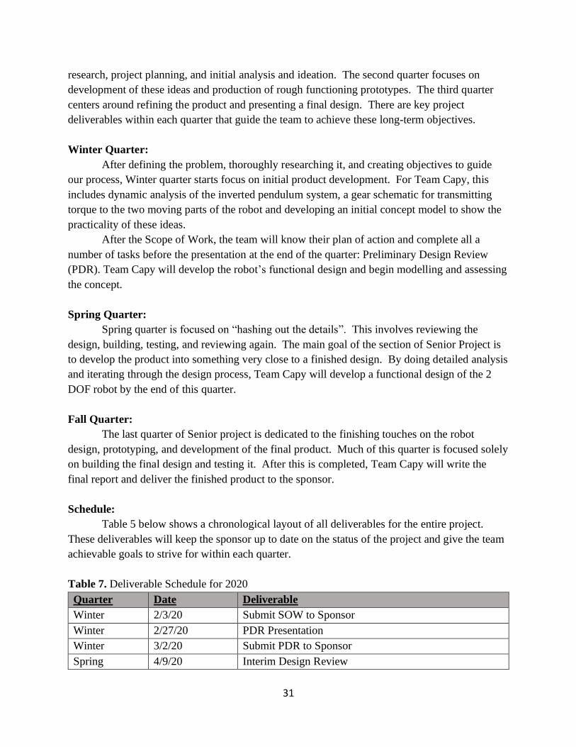
Schedule:
Table 5 below shows a chronological layout of all deliverables for the entire project.
These deliverables will keep the sponsor up to date on the status of the project and give the team
achievable goals to strive for within each quarter.
Table 7. Deliverable Schedule for 2020
Quarter Date Deliverable
Winter 2/3/20 Submit SOW to Sponsor
Winter 2/27/20 PDR Presentation
Winter 3/2/20 Submit PDR to Sponsor
Spring 4/9/20 Interim Design Review
32
Spring 4/30/20 CDR Presentation
Spring 5/4/20 Submit CDR to Sponsor
Spring 6/4/20 Manufacturing & Test Review
Fall 10/20/20 Confirmation Prototype Review
Fall 11/24/20 FDR Presentation
Fall 11/27/20 Senior Project Expo
EDIT- 2/24/2020
Moving forward from PDR, Team Capy will work to develop the project for Interim
Design Review and Critical Design Review. This will involve further developing intricate
design details and finishing a prototype. Additionally, Spring quarter will involve dynamic
analysis of the system and beginning simulation and programming for the final product. This
quarter will house a majority of the finer detail development and end with a functional
simulation and mechanical design.
EDIT – 3/12/20
After presenting and sharing the PDR with the project sponsor Professor Simon Xing,
Team Capy received the following feedback. Xing suggested that the hip design for the legs
includes some casing for the motors to prevent large impacts. Similarly, Team Capy is strongly
encouraged to consider friction effects because of incorrect gear ratios seen as impedance to the
motor. Professor Xing has also asked for additional requirements not originally listed in the
Scope of Work. These include a force sensor on either the “foot” of the leg or the landing pad of
the test stand, as well as a position measurement device to know the hips position and velocity at
all times. Sponsor Xing was very pleased with the presentation and the direction of the project
thus far.
EDIT – 5/12/20
As of early May, there has been a change in the Scope of the project. New requirements
were brought to light which led to a complete redesign of the test stand. The leg design
remained on the same development path after PDR. This change was unexpected and came very
late in the design process, but after a lot of work, ultimately resulted in an improved design.
EDIT – 11/19/20
The senior project process worked well for us as a team. While the year was not without
flaws for Team Capy, the resources available to us and the direction we were given were a great
benefit to completing the deliverables. A specific process that Team Capy found very helpful and
used many times over is weighted decision matrices.
Team Capy redesigned the final design of the leg, casing and test stand over summer.
That is generally very late for design work to be done. While everything came together in the
end, for our next project we have all agreed that there needs to be more communication in the

33
opening quarter for sponsors to accept, reject or advise on, concept designs. In our next design
project, we will focus on increased communication to get designs approved early in the process.
Another element Team Capy did not consider until approaching the end of the senior
project experience is testing. The scope of the project deliverables did change drastically in
October, however there was no plan in place for testing. As a team we have discussed this as an
oversight on our end and noted that a part of designing a project is also designing measurable
testing methods.
9. CONCLUSION & RECOMMENDATIONS
The Scope of Work is meant to showcase Team Capy’s understanding of the problem and
goals to move forward on the project. Additionally, it is a tool to correspond with Professor
Xing to make sure the team’s problem assessment and goals align with his. Our goal over the
next year is to develop a 2 Degree of Freedom robotic leg that can accurately jump 10 cm or
more, while costing less than $600. This project is the basis upon which Cal Poly will build a
full quadruped robot to use for both research and teaching. After thorough research of
quadrupedal robots and general biomimetic-leg mechanics, the design of Cal Poly’s 2DOF robot
leg has a clear route ahead of it. The next steps are to select a scale based on selected actuator
capabilities, develop a mathematical model (Equations of Motion) of the two-bar system, and
finish a preliminary design for the product. The results of these objectives will make up the body
of our next deliverable, due on February 27: Preliminary Design Review (PDR).
EDIT- 2/24/2020
Team Capy has developed a preliminary mechanical concept design. This design is
composed of a wire-guide stand, gears connecting the motors to the actuators, a gear-set actuator
for the upper leg, and a belt-drive for the lower leg actuator. The budget has been raised to
$1100, excluding the stand, because of the motor requirements and costs. Looking toward CDR,
Team Capy will further develop the concept design according to PDR critique. The team will
build and test a prototype and return to the design phase based on the results.
EDIT – 11/19/20
The deliverable for the past year was to develop of 2 degree of freedom robotic leg that
can accurately jump 10 centimeters while costing less than $600. Included within that phrasing is
a testing mechanism. Team Capy succeeded in developing a 2 degree of freedom robotic leg,
while spending much more than $600 dollars and without confirming whether the leg jumps.
Very early in the project process the budget was increased to $3000, and it became clear that the
controls simulation and electronics were not going to be ready for Team Capy to connect to.
Team Capy is very content with the state of the project today. As a team it was
understood that we are the first of many projects to be working towards the greater goal of
building a quadruped robot at Cal Poly. With that understanding, we are confident that our

34
project provides clear paths, and abilities to improve on and achieve the goal. Primarily we are
proud of the test stand. After many unique ideas and designs, we finally achieved to design and
build an easy to assemble, sturdy, long-lasting test stand. We are confident that this test stand
will be used to analyze many leg and motor designs.
Team Capy did not achieve to connect electronics and test the leg. In retrospect, the
project proposal of designing a leg as well as controls simulation might have been out of reach.
We believe that was good for us as a team, because we reached for a goal further than what we
eventually reached. While there is the negative viewpoint of not having achieved all we set out to
do, the glass half full viewpoint which we choose to see is that we designed and built a better leg
and test stand because we knew of the next steps.
Had Team Capy had a re-do with this project, we would increase communication efforts
with our sponsors. The design changes that happened late in the process were encouraged by our
sponsors, and led to better, more effective designs. While the senior project process is meant as a
learning tool for the students more so than a project labor bank for sponsors, our sponsors guided
us towards options and design ideas we did not know existed. There is a thin line between the
sponsors telling us what to do and suggesting we look for a different solution. During the process
Team Capy did not feel our sponsors overstepped in recommending ideas, as such we would
have increased communications looking back.
Listed below are recommendations for future teams and our sponsors:
Recommended Design of Acrylic Casing:
Team Capy suggests utilizing an acrylic casing for safety when operating the leg on the test
stand. While the legs are safe, an additional layer of safety will ensure that during operation it is
not possible for a bystander to get pinched or electrocuted. Using clear acrylic will allow
operators to still see what is happening. Implementing a switch will require the acrylic box to be
in place before movement is possible, forcing the safety precaution to be used.
The following BOM is based on the recommendation made above. Specifically, the amount of
acrylic casing calculated for surrounds the entire test stand on all 5 sides (not bottom). The next
team leading this project should plan to revisit these measurements and vendor.
Subassembly Part Name Part Vendor Price Quantity
Acrylic Casing 48” x 96” x 1/8” Clear
Acrylic Sheet
Home Depot $129.00 5
Recommended Methods of Data Collection
Data collection is required in order to complete a feedback loop for the control system. By
collecting specific location data, one can extrapolate velocity, acceleration and further
displacement derivatives of the specific parts they are looking at. Based on this output, the
control system will be able to modulate the motors’ torque inputs to the desired specification.
Team Capy recommends that the next projects utilize one of two methods to analyze the motion
35
of the Robotic Leg. The first is by using a slow-motion camera and specific background set up to
capture frames of the legs and motor casing at different positions. The second recommendation is
to use non-contact encoders. The decision of which method to use should be influenced by the
budget of the next team.
Using a camera to capture slow motion videos of the leg in motion is the inexpensive yet
complicated way to analyze the motion of the leg. Using rudimentary dynamics equations and
treating the legs as rigid bodies, the position, velocity, and acceleration vectors (in addition to
further position derivatives) can be extrapolated. This can be done by comparing the different leg
angles by stepping time in addition to monitoring motor casing location.
Surprisingly, any modern (iPhone 8 and on) Apple phone camera has the capability to capture
slow motion video at 240 frames per second, but may not be able to feed live information to a
control system. That framerate is more than enough to be able to accurately analyze the motion
of the legs; we recommend finding a way to use the iPhone in this system or purchasing a camera
with comparable framerate to capture and send location data to the control system. We
recommend using a background with a scale that accounts for the location of the leg relative to
the camera, the distance between robotic leg and background, and is easy to read against. An
example background is a grid in which the boxes get increase in area proportionally to the
distance from the camera’s center of view.
A non-contact, optical, linear encoder is another option for collecting the location data of the leg.
It would be far more accurate than the camera method but would only give one datapoint: motor
casing location. This method would be much easier to incorporate into the control system as it
simply outputs a voltage based on the encoder’s location. The motor casing velocity,
acceleration, and further derivatives could be extrapolated from this datapoint. The input torque
from the motors can be modulated based on this single output.
Optical linear encoders are both very accurate and far less expensive than their magnetic
counterparts. The price depends on three main factors: accuracy, length, and application. The
most expensive ones have industrial applications and are built to withstand much higher loads
than are required for our use case. We recommend basing the encoder decision around length, as
any encoder that size should provide more than enough accuracy and toughness for this
application. The chosen encoder must span the 4 ft length of the guide rail.
The next team’s design choice will be between these two options, deciding between the accuracy
and the amount of the system they want to define. In an optimal scenario, an encoder would be
used to measure the motor casing location while a camera monitors the legs’ rotational position
(velocity, acceleration, etc.).
Recommended Part Comparison
Due to restrictions set by the pandemic, Team Capy was forced to fabricate and assemble mostly
off campus. As such we did not have access to many measuring devices such as a scale or
calipers. We recommend that the next team to take over weigh, measure and compare the

36
fabricated components against the values the CAD models indicate. Knowing the real weight and
dimensions will greatly help in motion analysis.
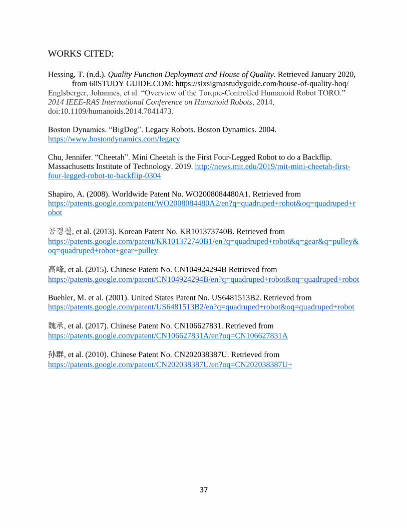
37
WORKS CITED:
Hessing, T. (n.d.). Quality Function Deployment and House of Quality. Retrieved January 2020,
from 60STUDY GUIDE.COM: https://sixsigmastudyguide.com/house-of-quality-hoq/
Englsberger, Johannes, et al. “Overview of the Torque-Controlled Humanoid Robot TORO.”
2014 IEEE-RAS International Conference on Humanoid Robots, 2014,
doi:10.1109/humanoids.2014.7041473.
Boston Dynamics. “BigDog”. Legacy Robots. Boston Dynamics. 2004.
https://www.bostondynamics.com/legacy
Chu, Jennifer. “Cheetah”. Mini Cheetah is the First Four-Legged Robot to do a Backflip.
Massachusetts Institute of Technology. 2019. http://news.mit.edu/2019/mit-mini-cheetah-first-
four-legged-robot-to-backflip-0304
Shapiro, A. (2008). Worldwide Patent No. WO2008084480A1. Retrieved from
https://patents.google.com/patent/WO2008084480A2/en?q=quadruped+robot&oq=quadruped+r
obot
공경철, et al. (2013). Korean Patent No. KR101373740B. Retrieved from
https://patents.google.com/patent/KR101372740B1/en?q=quadruped+robot&q=gear&q=pulley&
oq=quadruped+robot+gear+pulley
高峰, et al. (2015). Chinese Patent No. CN104924294B Retrieved from
https://patents.google.com/patent/CN104924294B/en?q=quadruped+robot&oq=quadruped+robot
Buehler, M. et al. (2001). United States Patent No. US6481513B2. Retrieved from
https://patents.google.com/patent/US6481513B2/en?q=quadruped+robot&oq=quadruped+robot
魏承, et al. (2017). Chinese Patent No. CN106627831. Retrieved from
https://patents.google.com/patent/CN106627831A/en?oq=CN106627831A
孙群, et al. (2010). Chinese Patent No. CN202038387U. Retrieved from
https://patents.google.com/patent/CN202038387U/en?oq=CN202038387U+
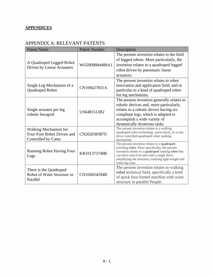
A - 1
APPENDICES
APPENDIX A: RELEVANT PATENTS
Patent Name Patent Number Description
A Quadruped Legged Robot
Driven by Linear Actuators WO2008084480A1
The present invention relates to the field
of legged robots. More particularly, the
invention relates to a quadruped legged
robot driven by pneumatic linear
actuators.
Single Leg Mechanism of a
Quadruped Robot CN106627831A
The present invention relates to robot
innovation and application field, and in
particular to a kind of quadruped robot
list leg mechanism.
Single actuator per leg
robotic hexapod US6481513B2
The present invention generally relates to
robotic devices and, more particularly,
relates to a robotic device having six
compliant legs, which is adapted to
accomplish a wide variety of
dynamically dexterous tasks
Walking Mechanism for
Four-Foot Robot Driven and
Controlled by Cams
CN202038387U
The present invention relates to a walking
quadruped robot technology, particularly, to a cam
drive controlled quadruped robot walking mechanism.
Running Robot Having Four
Legs KR101373740B
The present invention relates to a quadruped
traveling robot. More specifically, the present invention relates to a quadruped running robot that
can drive each foot unit with a single drive,
simplifying the structure, realizing light weight and
reducing costs.
There is the Quadruped
Robot of Waist Structure in
Parallel
CN104924294B
The present invention relates to walking
robot technical field, specifically a kind
of quick four-footed machine with waist
structure in parallel People.

B - 1
APPENDIX B: ACTUATOR SPECIFICATIONS

C - 1
APPENDIX C: QUALITY FUNCTION DEPLOYMENT
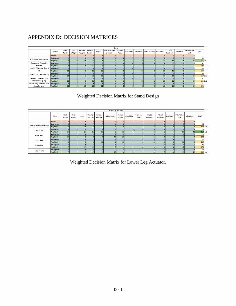
D - 1
APPENDIX D: DECISION MATRICES
Weighted Decision Matrix for Stand Design
Weighted Decision Matrix for Lower Leg Actuator.
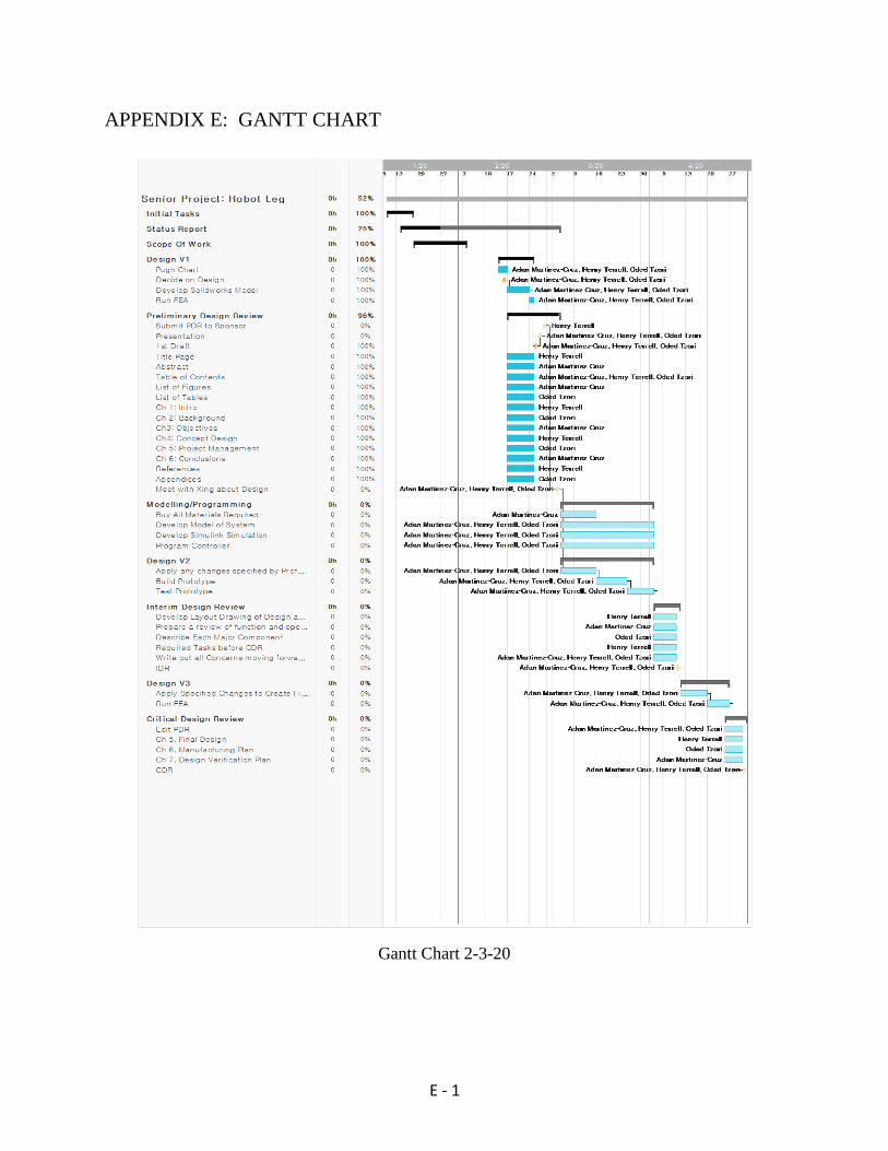
E - 1
APPENDIX E: GANTT CHART
Gantt Chart 2-3-20
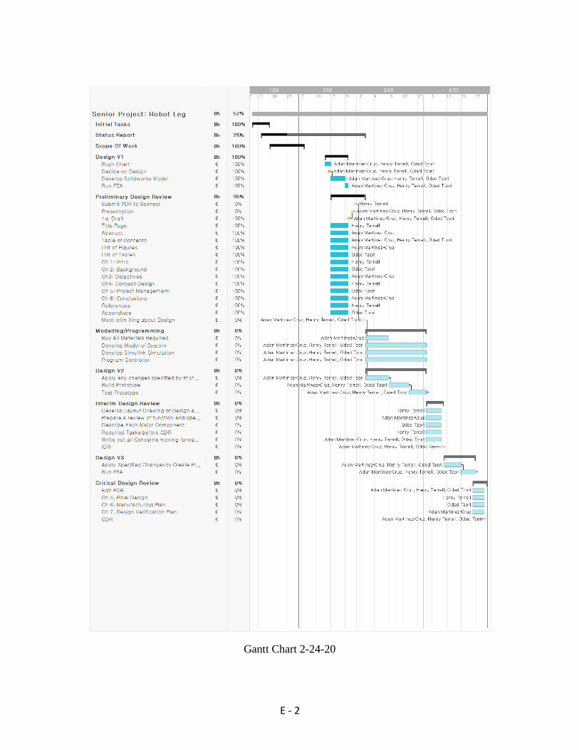
E - 2
Gantt Chart 2-24-20
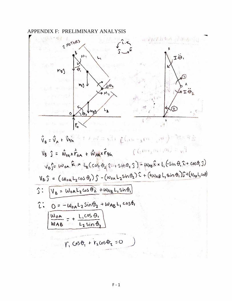
F - 1
APPENDIX F: PRELIMINARY ANALYSIS
Scanned with CamScanner
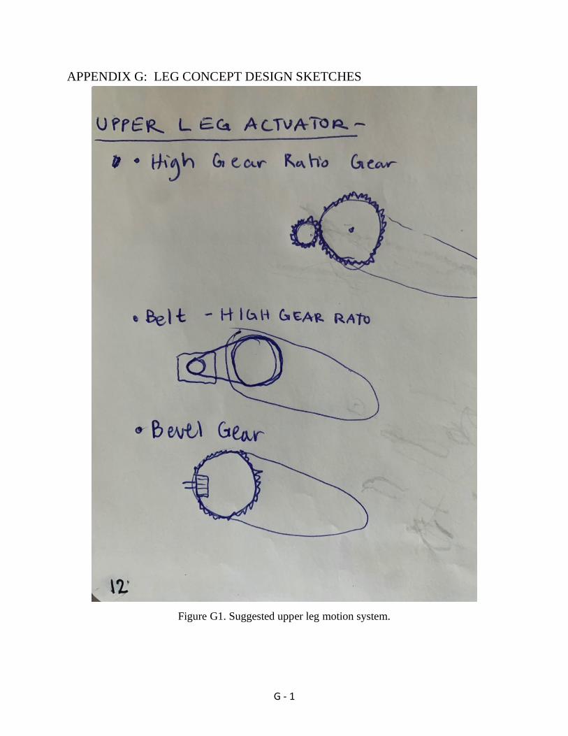
G - 1
APPENDIX G: LEG CONCEPT DESIGN SKETCHES
Figure G1. Suggested upper leg motion system.
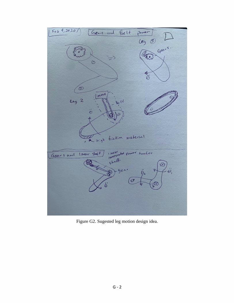
G - 2
Figure G2. Sugested leg motion design idea.

G - 3
Figure G3. Lower leg concept idea.
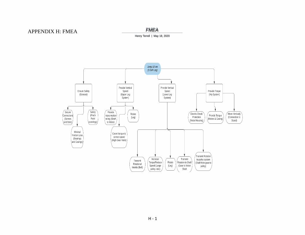
H - 1
APPENDIX H: FMEA
F M E A H e n r y
T e r r e l l | M a y
1 8 , 2 0 2 0

I - 1
APPENDIX I: BILL OF MATERIALS

J - 1
APPENDIX J: SIGNED EXPECTATIONS & DELIVERABLES

J - 2
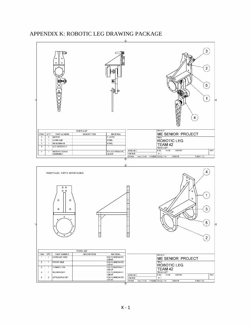
K - 1
APPENDIX K: ROBOTIC LEG DRAWING PACKAGE

K - 2
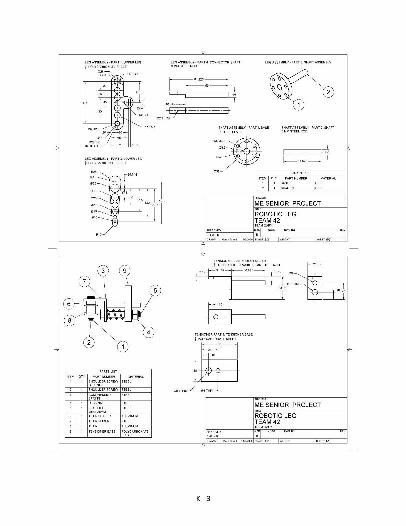
K - 3
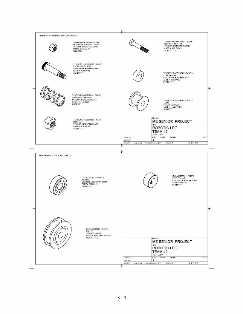
K - 4
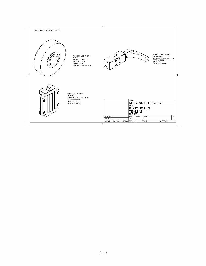
K - 5

L - 1
APPENDIX L: TEST STAND DRAWING PACKAGE

L - 2
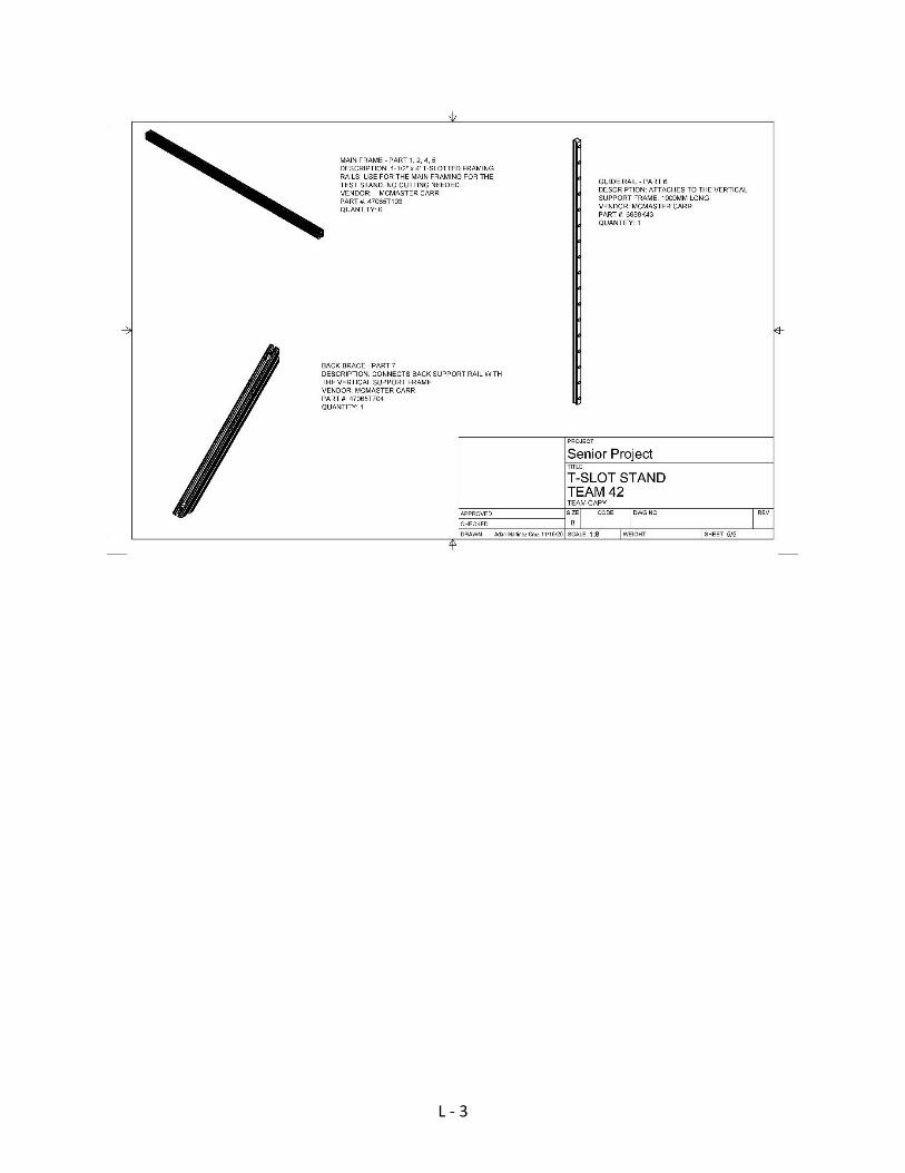
L - 3