final coop report
TRANSCRIPT
King Fahd University of Petroleum & Minerals
College of Applied Engineering
Electrical Engineering Department
COOP Final Report
Pipeline leak Detection System
SAUDI ARAMCO
Done by: Ahmad Abdulhadi Alnakhli
ID# 200953090
Advisor: Dr. Mohammad K. Alghamdi
1/3/2015

i
ABSTRACT
This report will introduce a full description of training organization, the department I
have worked with and our activities and a complete discussion of two case studies I have
done in my cooperative training program with Saudi Arabian Oil Company during the
period from June 11, 2014 through December 31, 2014. The unit I have worked with
project management team which was rolled under pipelines and communications projects
department. They are responsible of organizing projects assigned to them following
proper management skills.
This report is divided into five chapters starting with a brief background about Saudi
Armaco and its history, passing through training activates done in 28 week of the
program and finalizing in three chapters that include a description of pipeline leak
detection system generally at the beginning and ending with complete description of two
case studies of two measurement types of leaks occurring in pipeline field.
The first case study is about acoustic sensors and its application for measuring pipeline
leaks technique used by Saudi Aramco in pipeline rehabilitation project to enhance the
safety and fast response of hazardous events. Furthermore, this report is introducing
instrumentation features used and communication system responsible for alerting control
room of any leak event. The second case study is an explanation of different type of
measurement using the mean of fiber optic sensing which can be used generally in pipes
containing hydrocarbon content by measuring its temperature variations.

ii
ACKNOWLEDGMENTS
Firstly, I thank Allah for his guidance and kindness protection through my whole life.
Also I thank my parents for their support and their continues care of me starting from the
day I have born until now they were always by my side guiding and supporting in every
step I am taking through my life.
I would like to thank my university King Fahd University of Petroleum & Minerals that
gave continues well-education not only in science and engineering things but also in
ways of communicating with people who are came from different societies. Giving me
such assignment of training was gratefully helpful for me to practice the real job and
applying my know lodgment.
Also I would like to thank SAUDI ARAMCO company which gave this opportunity of
working with qualified engineers and to learn from them all the aspects that I needed
during my training program.
Special thanks to Eng. Ahmed Alnemr and Eng. Jafar Alali. Seriously without their
helpful gaudiness and support I would not be able to accomplish my training tasks. Thank
you Ahmed and Jafar. Also, I would like to thank Eng. Sami Mohammed who was my
COOP advisor in the company. Thank you Mr. Sami.
My deep appreciation and special thanks also for my KFUPM COOP advisor Dr.
Mohammed Al-ghamdi. He was always there to answer any concerns I had during my
training.
Finally, I really have enjoyed this experience and gain from so much learning that I will
be using in my future life.
King Fahd University of Petroleum and Minerals, Dhahran
Electrical Engineering Department
iii
Table of Contents Page #
ABSTRACT ..................................................................................................... i
ACKNOWLEDGMENTS ............................................................................ ii
CHAPTER 1: INTRODUCTION: ............................................................... 1
1.1: Objectives and Motivations ............................................................. 1
1.2: Environment contamination and Risks: ......................................... 1
CHAPTER 2: Training Organization and COOP Assignment: ............... 3
2.1: Training Organization (SAUDI ARAMCO): ......................................... 3
2.2: Pipelines and Communications Projects Department: ..................... 3
2.3: My COOP Plan and Training Activates: ....................................... 4
2.3.1: Project Management Team: ......................................................... 4
2.3.2: Sites Visit: ................................................................................... 5
2.3.3: Attending meeting: ...................................................................... 8
2.3.4: E-learning Courses: ...................................................................... 9
2.3.5: Familiarizing with drawings of the projects: ................................ 9
2.3.6: Required Tasks: ......................................................................... 10
Chapter 3: Introduction to pipeline leak detection system ..................... 12
3.1: PLDS System: ................................................................................ 12
3.1.1: PLDS layers: .............................................................................. 13
3.2: Sensitivity Study ............................................................................ 14
3.2.1: Sensitivity: ................................................................................. 14
3.2.2: Reliability: ................................................................................. 15
3.2.3: Accuracy: ................................................................................... 15
3.2.4: Robustness: ................................................................................ 16
3.3: Leak Causes: .................................................................................. 16
3.4: PLDS technologies: ........................................................................ 17
iv
Chapter 4: Case Study I: Acoustic Pressure Wave Leak Detection
System: .......................................................................................................... 18
4.1:Introduction: ................................................................................... 18
4.3: System components: ...................................................................... 20
4.3.1: Pressure Sensors: ....................................................................... 20
4.3.2: Field Signal Processing (FSP): ................................................... 21
4.3.3: Control Center: .......................................................................... 23
4.4: APLDS operation principles: ........................................................ 25
4.4.1:System Advantages ..................................................................... 26
Chapter 5: Case Study II: Fiber Optic Sensing in Pipeline Projects: .... 27
5.1: Introduction: .................................................................................. 27
5.2: Distributed Temperature Sensing: ............................................... 28
5.3: DTS components: ........................................................................... 29
5.4: Principle of operation: ................................................................... 31
5.4.1: Leakage detection: ..................................................................... 32
5.5:Fiber optic features: ....................................................................... 33
5.6:Fiber Optics Positioning: ................................................................ 34
Conclusions & Recommendations: ............................................................ 35
References ..................................................................................................... 37
APPENDIX A ............................................................................................... 38
APPENDIX B ............................................................................................... 40
APPENDIX C ............................................................................................... 42
APPENDIX D ............................................................................................... 44

v
List of Figures
Figure 1- Control Cabinet ................................................................................................................ 6
Figure 2- Motor Operated Valve at the site ..................................................................................... 7
Figure 3 - Example of weakly progress meeting ............................................................................. 8
Figure 4- Electrical Classification Report Cover page .................................................................. 11
Figure 5- LDS block diagram ........................................................................................................... 11
Figure 6- Acoustic Pipeline Leak Detection System (block diagram) ............................................. 19
Figure 7 - WIKA E10 E-10 pressure sensor ..................................................................................... 20
Figure 8 - WIKA E10 E-11 pressure sensor .................................................................................... 20
Figure 9 - FSP ................................................................................................................................ 21
Figure 10 - WaveAlert field Processor .......................................................................................... 23
Figure 11 - Typical Configuration of APLDS [6] .......................................................................... 24
Figure 12 - PLDS system drawing [8] ........................................................................................... 24
Figure 13 - propagated light spectrum ........................................................................................... 28
Figure 14- DTS basic components ................................................................................................. 29
Figure 15 - Fiber Optic Cable .......................................................................................................... 33
Figure 16 - Cables positioning for buried pipeline ........................................................................ 34
Figure 17 - cable positioning when pipe contains gas ................................................................... 34
Figure 18 - Training Plan_page1 ................................................................................................... 40
Figure 19- Training Plan_page2 .................................................................................................... 41
Figure 20 - Certificate of Training Completion ............................................................................. 44

vi
List of Tables
Table 1 - MOV technical specifications .......................................................................................... 7
Table 2 - sensitivity Requirements for Liquid & Gas .................................................................... 15
Table 3 - Pressure Sensors Spicifications ...................................................................................... 21
Table 4- Advantages of APLS ....................................................................................................... 26
Table 5- Fiber Optic Sensor (Tech. Spec.) ..................................................................................... 30
Table 6- Location Classes 1 ........................................................................................................... 42
Table 7 - Location Classes 2 .......................................................................................................... 42
Table 8 - Location Classes 3 .......................................................................................................... 42
Table 9 - Location Classes 4 .......................................................................................................... 42
1
CHAPTER 1: INTRODUCTION:
1.1: Objectives and Motivations
Pipeline networks are the most economic and safest mode of transportation for oil, gases
and other fluid products. As a means of long-distance transport, pipelines have to fulfill
high demands of safety [4]. Short pipeline distances have also a risk to face leaks
conditions. Therefore, Saudi Aramco as an example of oil companies that deal with
multiple types of pipelines to connect different regions all over the kingdom area for
supplying fuel that classified some times as extremely hazardous materials. Therefore
they consider delivering it safely is a competitive challenge. Over the years there was
several ways of controlling the safety of pipes leaks that developed by the company itself
or a contractor party.
Instrumentation engineers have to fulfill and sustain cretin features and characteristics of
each product introduced by whatever party considering all procedures and standard that
have been sit up by Saudi Aramco. Therefore leak detection pipeline leak detection has
an essential role for every pipeline project nowadays.
1.2: Environment contamination and Risks:
Due to the rapid increase in the number of pipeline being designed and constructed, the
demand of finding the safest mode to detect and control leaks in transported hazardous
and toxic products carried in pipelines is highly needed. While Small leaks have the
potential to turn into an expensive and dangerous event if not detected and stopped in
time, risks can also include risk to equipments, personnel safety, environmental
contamination, production losses, cleanup and medical expenses.

2
This report is going to discuss and explain two types of technologies used worldwide to
detect and locate leaks in pipeline.

3
CHAPTER 2: Training Organization and COOP Assignment:
2.1: Training Organization (SAUDI ARAMCO):
The company that I had the opportunity to do my cooperative training program is Saudi
Arabian Oil Company (Saudi Aramco). Saudi Aramco, a fully integrated, global
petroleum and chemicals enterprise, is the state-owned oil company of the Kingdom of
Saudi Arabia.
Throughout 80-year history the company has become a world leader in hydrocarbons
exploration, production, refining, distribution, shipping and marketing. Saudi Aramco has
introduced proven conventional crude oil and condensate reserves of 260.2 billion
barrels. Moreover, Saudi Aramco average daily crude production in 2013 was 9.4 million
barrels per day. During my training period I have assigned to work with in Pipelines &
Communications Projects Department that located in Dammam Office Building.
2.2: Pipelines and Communications Projects Department:
The department I have assigned to work with is pipelines and communications projects
department. This department is responsible for handling the piping and communication
project from the zero level up to hand in projects completed. To illustrate, the department
has to find and handle with every task to complete a certain projects. As an example of
those tasks is to get the suitable contractors for designing and construct projects and order
all the materials that each project will need.
To complete a certain project the department should divide the work to different
members of the department to work as a team. For example, material specialist team
responsible for order and purchase the materials for the project. Other teams are highly
4
needed and included during processing different projects such as project management
team, cost estimation, construction team and others. During my cooperative training
program I have worked with Saudi Aramco Project Management Team (PMT) where
they was responsible of handling pipelines projects in eastern area.
2.3: My COOP Plan and Training Activates:
As a beginning of my training activates I have learned and accomplished different tasks and
activities that usually focused in understanding the job nature in the department. In this
section of the report a list of activities, assignments and tasks that were completed during my
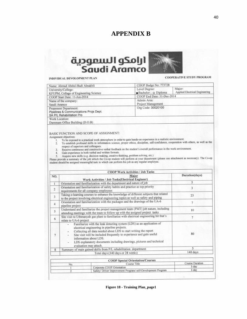
training program will be introduced. The scheduled training plan is listed in Appendix B.
2.3.1: Project Management Team:
During the first period of the training I have worked as a member of Saudi Aramco
Project Management Team (SAPMT). A project management team is a team whose
members usually belong to different groups, functions and are assigned to activities for
the same project. A team can be divided into sub-teams according to need.
Most project teams require involvement from more than one department; therefore most
project teams can be classified as cross functional team. The project management team
usually consists of a variety of members often working under the direction of a project
manager or a senior member of the organization. As a member of the PMT you need to
have the right combination of skills, abilities and personality types to achieve
collaborative tension. Teams can be formulated in a variety of ways. The most common
method is at the discretion of a senior member of the organization. At this team my job
5
was to follow up with the drawings of the project assigned to them focusing in the
electrical parts in the drawings.
2.3.2: Sites Visit:
As a PMT member we were assigned to visit different sites of the project frequently. Those
visit are assigned to us to be able to familiarize and understand the job nature technically.
Contractors with Saudi Aramco need to visit the sites from time to time and we as a PMT we
should arrange those sites visit for them to complete the design level of the project. During
the training period we have completed several sites visit that included different locations
divided into three periods. In each site visit I have to get familiar to several devices and
machines and make comments on my own notebook.
1) At the first period, Qatif-junction was visited. The visit was consist of three different
locations which are entering cabinet in communication tower there to see the new
fiber optic systems included recently under rehabilitation of the pipeline project in
that area. Moreover, Juaymh-junction and Shadqm gas plant were also included in
our schedule.
2) At the second period of the training:
Ras Tanoura refinery (RT-Gart-1) was visited by the team. The purpose of the visit was
to check whether there is an available room in the control cabinet to install external
panels for BI-768 project. Figure 1 showing a sample of one cabinet that have installed
pnales.

6
Note: We found that there is confusion between PMT member and technicians there that
causes us to arrange later visit to get the final decision from RT-GATR-1.
Figure 1- Control Cabinet
7
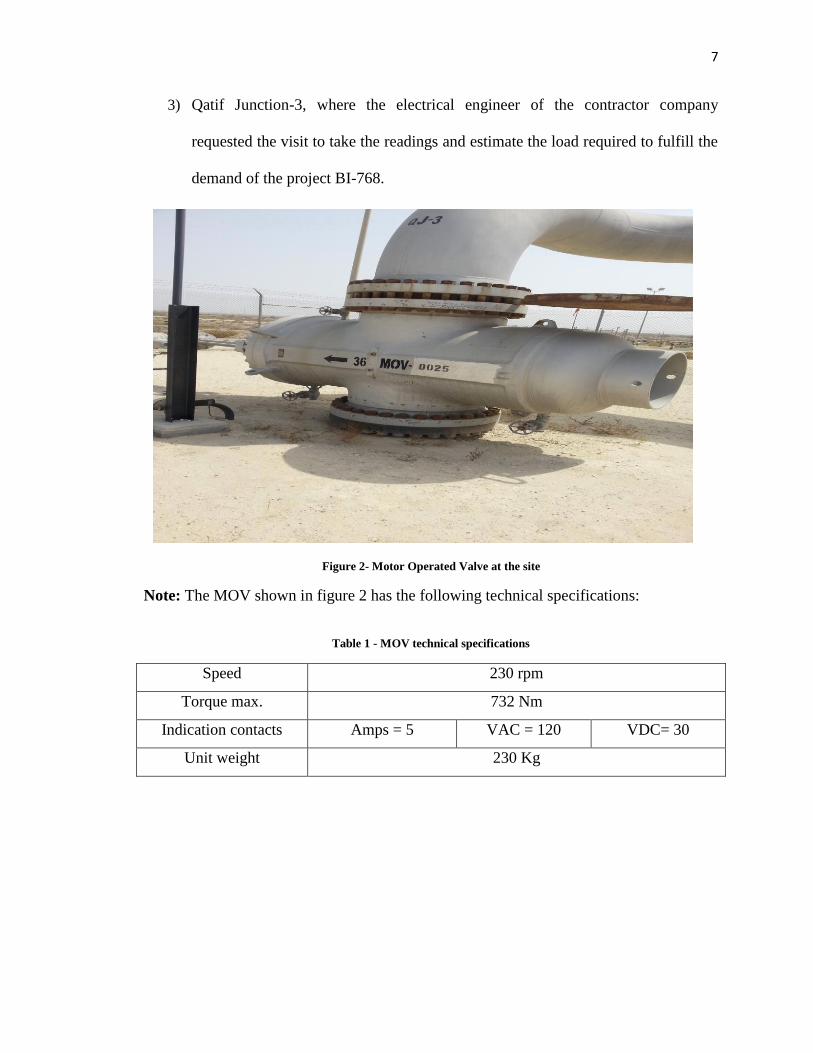
3) Qatif Junction-3, where the electrical engineer of the contractor company
requested the visit to take the readings and estimate the load required to fulfill the
demand of the project BI-768.
Note: The MOV shown in figure 2 has the following technical specifications:
Table 1 - MOV technical specifications
Speed 230 rpm
Torque max. 732 Nm
Indication contacts Amps = 5 VAC = 120 VDC= 30
Unit weight 230 Kg
Figure 2- Motor Operated Valve at the site

8
2.3.3: Attending meeting:
Starting from the second weak I have involved in the weekly meeting that summarize and
report the completed tasks during that week and discuss the uncompleted ones to follow up
with the contractor company as an essential part of SAPMT job. As an example, in the fourth
week the meeting was discussing some issues about the materials and how they are going to
order it at the exact time.
Weakly progress meeting: every Thursday we conduct a meeting with the
contracting company (SLFE) to follow up with the pending items in the design
level of the project. In figure 3, my name is shown in the attendance list.
Figure 3 - Example of weakly progress meeting
9
At 25th
of November in the last period of the training I have been introduced to an
expert in instrumentation engineering who was part of the team designed the leak
detection system (my cases study). A short meeting was done in the beginning,
then I had the chance to set with him many times which was tremendous help for
me to understand and complete my case study.
2.3.4: E-learning Courses:
Starting from the second week I get access to Saudi Aramco system. The courses were
selected during the training was to enhance my knowledge about different topics related
to the project I am included in. the main focus of E-courses was to involve general
electrical engineering topics as well as safety and piping background. They are short
courses usually completed in 2 hours.
E-learning Courses included:
- Fall protection
- Electric hazards
- Troubleshooting for Electric circuits
- H2S (Hydrogen Sulfide) awareness
- Saudi Aramco Safety handbook
- Motor operated valve description
- Circuit breakers
2.3.5: Familiarizing with drawings of the projects:
During the first period I have go over the packages and design drawings of the UA-6 project.
They consist of Saudi Aramco standards and schematic drawing of project areas technical
specification of certain topics. Moreover the design drawing of the design drawings of PLDS
that included two case studies I have selected were reviewed.
10
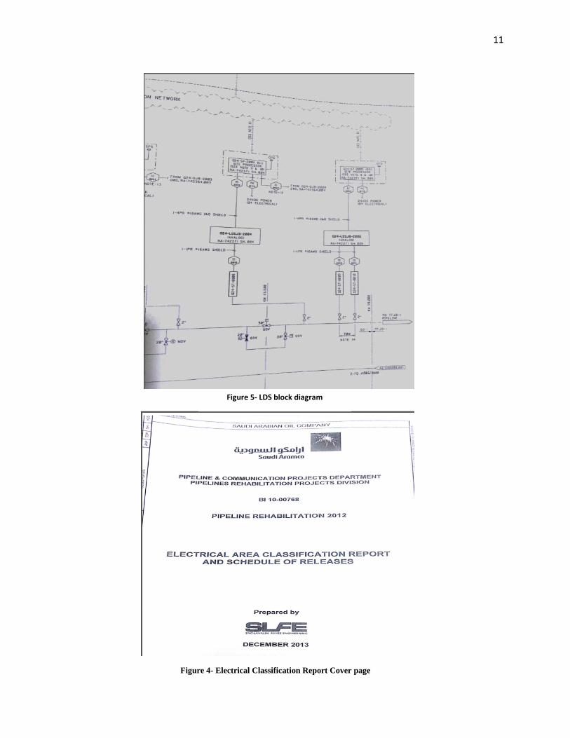
MR. Ahmed Alnemer who is a project engineer working with SAPMT saw that assigning
me read and write comments on the electrical area classification report done by SLFE.
The report was explaining the electrical classification in different areas of the project and
is specifying the work that should SAPMT be responsible for. For example, as you can
see from figure 5 PLDS block diagram is shown in detailed manner including how to
connect and figure the system. The following two figures are taken from the drawings
report.
2.3.6: Required Tasks:
During my second period on the training I was asked to prepare a presentation and report
about leak detection system and deliver it to my supervisor Mr. Sami Ismail and I may
publish it and present it in front of the project manager. The task is completely done and I
have delivered it to Mr. Sami. However, project manager Mr. Alsoqur could not make a
time to see my presentation.
11
Figure 4- Electrical Classification Report Cover page
Figure 5- LDS block diagram
12
Chapter 3: Introduction to pipeline leak detection system
3.1: PLDS System:
Pipeline Leak Detection System (PLDS) is a system comprising field sensors, means of
communications, field data collection and processing devices capable of detecting and
locating leaks along pipelines networks, managing nuisance without affecting
performance for specified PLDS application and generating leak events and displaying
system status information to pipeline control committee. In the coming sections and
chapters I may use several phrases related to pipeline engineering which you can find its
definitions in Appendix A [1]
PLDS is an integration of hardware and software, including sub-systems and components
parts, which as a whole, is capable of meeting the required performance level. Those
PLDS requirements can be summarized as the following according to Saudi Aramco
Engineering Standards (SAES-Z-003).
Firstly, PLDS have to detect the leaks when they occur, determine the location of the
leak, estimate the magnitude and this system has to be developed with an alert system of
leak events. According to SAES-Z-003 the selection of PLDS technology for onshore
pipelines network should meet the minimum performances list required which are listed
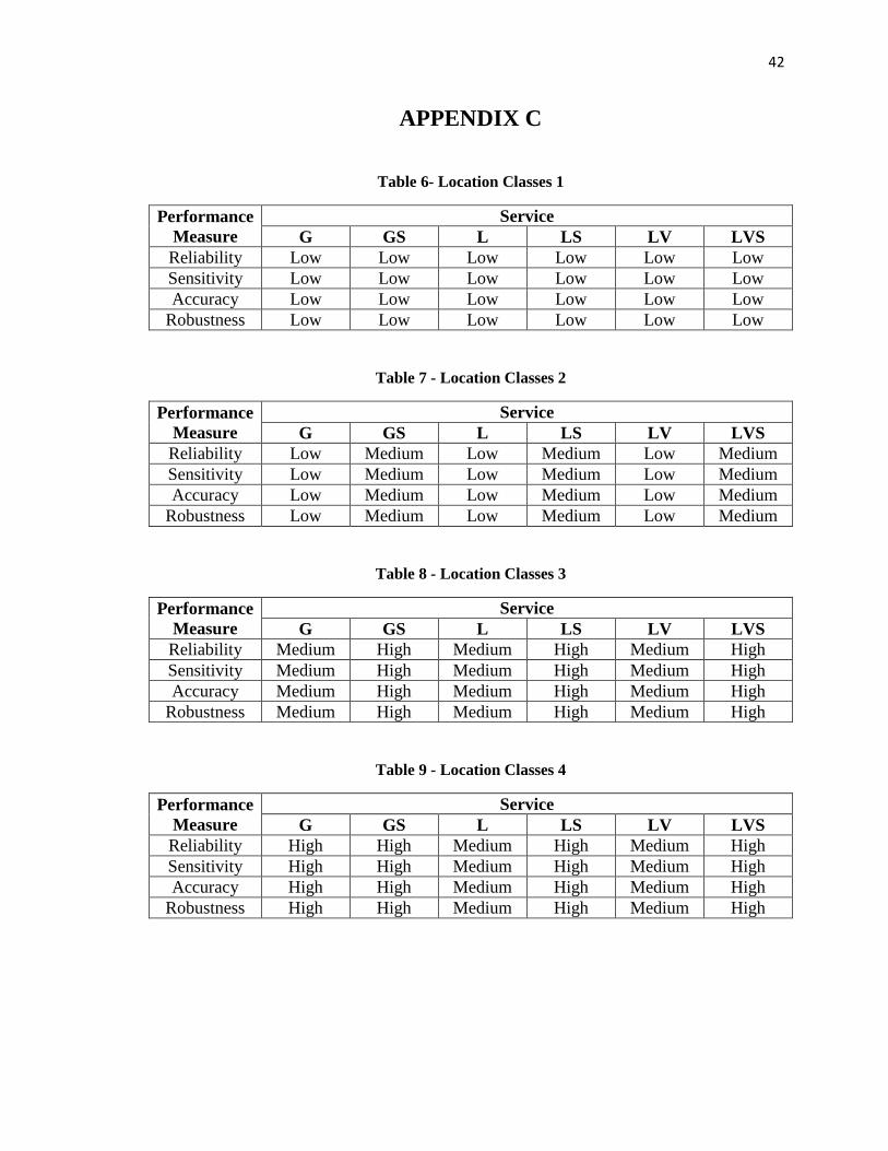
at table 2 through table 5 in Appendix C. Furthermore, a study of risk assessment shall be
done to evaluate the impact of major leak events on the neighboring community and
environments. This study has to consider the minimum amount of product leaked and its
impact on the surrounding areas until total isolation is received. Therefore, it will give
reasonable results for determining the required leak detection system performance listed
13
in table 2 to table 5 in Appendix C. The selection of technology will be used in detecting
should be approved by Process and Control System Department (P&CSD) during each
project proposal phase that cover leaking detection system considering communication
infrastructure, monitoring system and field instrumentation. Also, pressure, temperature,
density and flow of the pipeline should be considered beside pipeline configuration and
pipeline fluid type in selecting PLDS technology. For operating certain technology its
operating requirements shall be studied to give the high system performance. In the next
section, operating requirements (performance criteria) will be discussed. [2]
3.1.1: PLDS layers:
A PLDS is built on three layers:
1- Field layer: Field devices, including field instrumentation and data collection
devices or field processing unit. Instrumentation equipments include sensors,
cables, flow meters and pressure transducers which are classified either externally
or internally instruments. They measure parameters of the pipeline such as
pressure, temperature, flow of the fluid and the appearance of hydrocarbons. [4]
2- Communication layer: communication devices and links (i.e. protocols and
interface software). Supervisory Control and Data Acquisition (SCADA) is a
computer based system used in leak detection system for monitoring, processing,
transmitting, communicating and displaying data for the pipeline control
sectors.[4]
3- Central processing and display devices, including associated software & security
requirements.
14
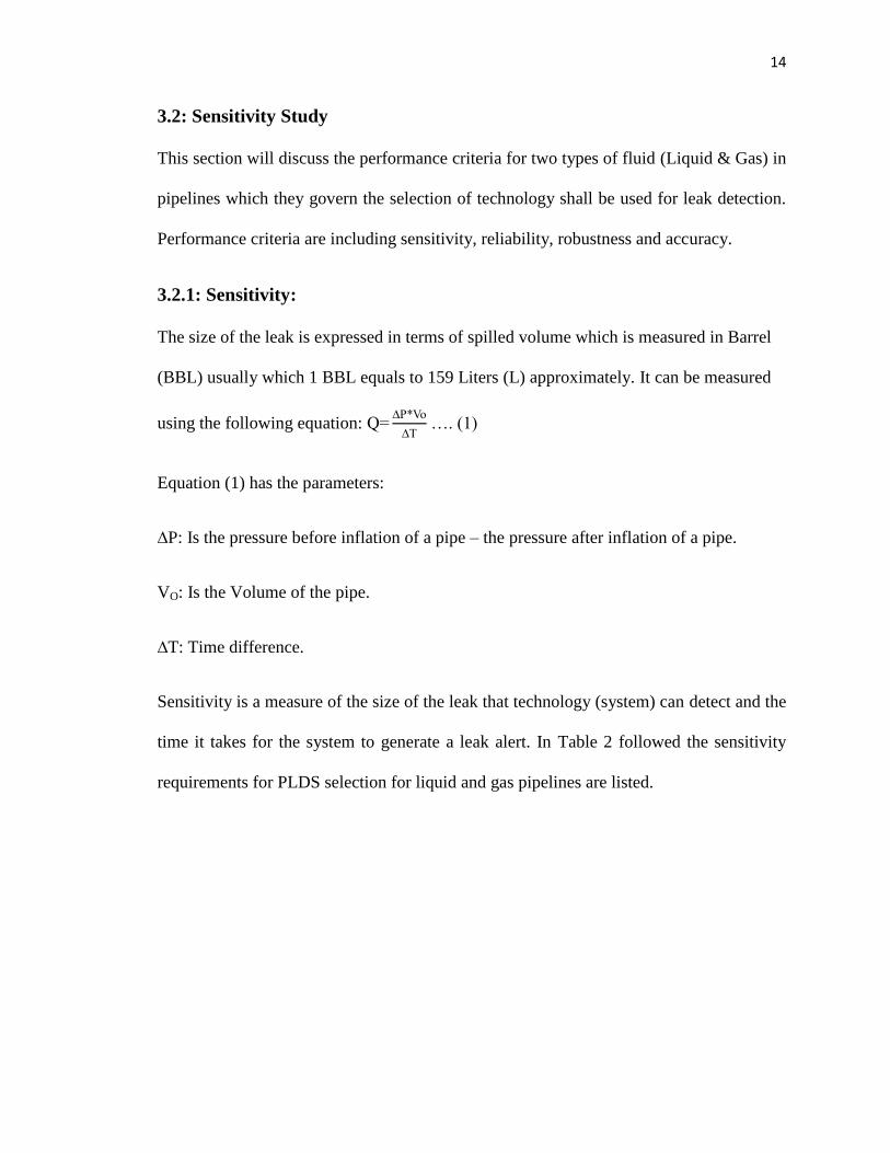
3.2: Sensitivity Study
This section will discuss the performance criteria for two types of fluid (Liquid & Gas) in
pipelines which they govern the selection of technology shall be used for leak detection.
Performance criteria are including sensitivity, reliability, robustness and accuracy.
3.2.1: Sensitivity:
The size of the leak is expressed in terms of spilled volume which is measured in Barrel
(BBL) usually which 1 BBL equals to 159 Liters (L) approximately. It can be measured
using the following equation:
…. (1)
Equation (1) has the parameters:
P: Is the pressure before inflation of a pipe – the pressure after inflation of a pipe.
VO: Is the Volume of the pipe.
T: Time difference.
Sensitivity is a measure of the size of the leak that technology (system) can detect and the
time it takes for the system to generate a leak alert. In Table 2 followed the sensitivity
requirements for PLDS selection for liquid and gas pipelines are listed.
15
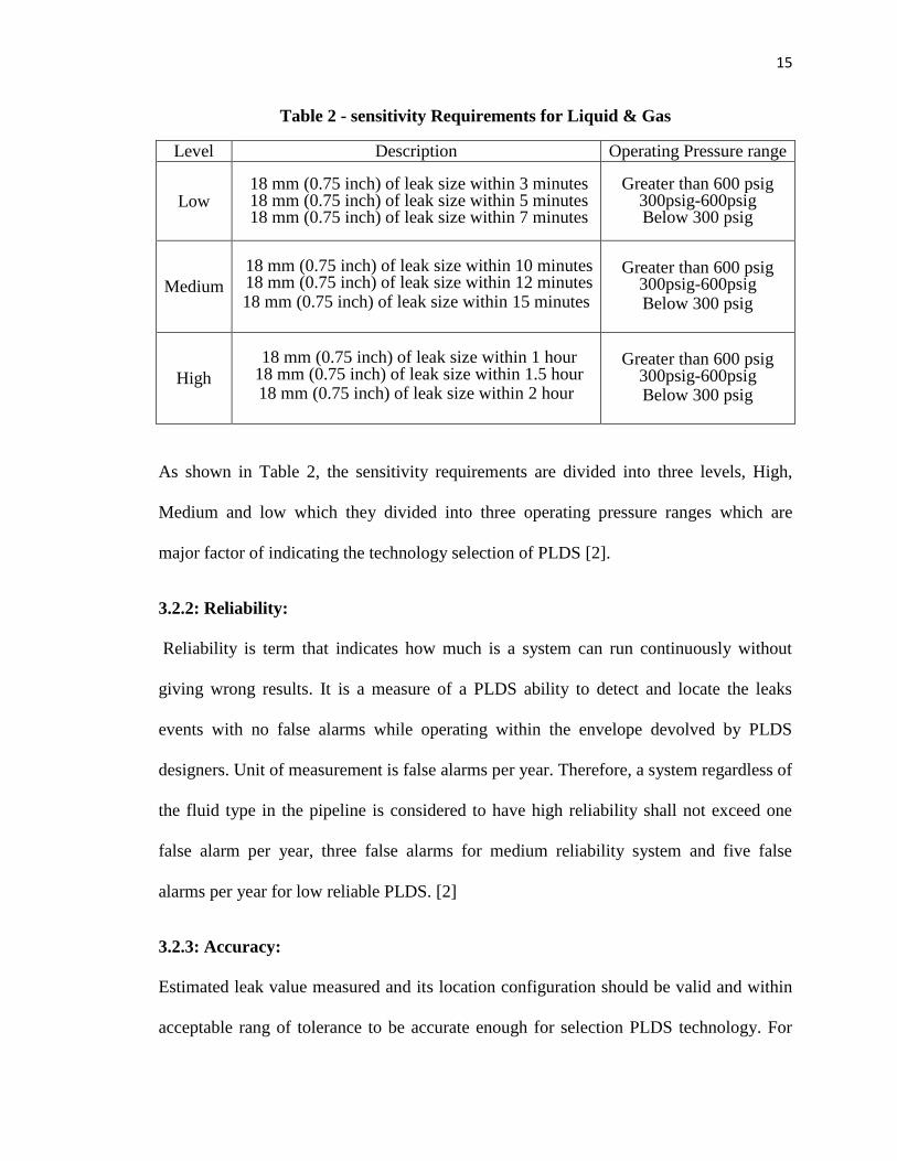
Table 2 - sensitivity Requirements for Liquid & Gas
Level Description Operating Pressure range
Low 18 mm (0.75 inch) of leak size within 3 minutes 18 mm (0.75 inch) of leak size within 5 minutes 18 mm (0.75 inch) of leak size within 7 minutes
Greater than 600 psig 300psig-600psig Below 300 psig
Medium
18 mm (0.75 inch) of leak size within 10 minutes 18 mm (0.75 inch) of leak size within 12 minutes 18 mm (0.75 inch) of leak size within 15 minutes
Greater than 600 psig 300psig-600psig Below 300 psig
High
18 mm (0.75 inch) of leak size within 1 hour
18 mm (0.75 inch) of leak size within 1.5 hour 18 mm (0.75 inch) of leak size within 2 hour
Greater than 600 psig 300psig-600psig Below 300 psig
As shown in Table 2, the sensitivity requirements are divided into three levels, High,
Medium and low which they divided into three operating pressure ranges which are
major factor of indicating the technology selection of PLDS [2].
3.2.2: Reliability:
Reliability is term that indicates how much is a system can run continuously without
giving wrong results. It is a measure of a PLDS ability to detect and locate the leaks
events with no false alarms while operating within the envelope devolved by PLDS
designers. Unit of measurement is false alarms per year. Therefore, a system regardless of
the fluid type in the pipeline is considered to have high reliability shall not exceed one
false alarm per year, three false alarms for medium reliability system and five false
alarms per year for low reliable PLDS. [2]
3.2.3: Accuracy:
Estimated leak value measured and its location configuration should be valid and within
acceptable rang of tolerance to be accurate enough for selection PLDS technology. For

16
high accurate level the system should not exceed ± 200 meters of its actual location, ±
1000 meters for medium accuracy and ± 2000 meters for low accuracy. [2]
3.2.4: Robustness:
A PLDS should be able to function probably and provide useful information regardless of
conditions changed of the pipelines operation or when data is lost or suspected. If the
accuracy of the system is affected by losing communication link or field sensors meaning
that it reduces the accuracy are called a medium robustness system. Whereas if no
effective accuracy reduction happened to the system is considered to be high robust
system and low robust system if the system have failed to give an accurate results when
losing communication link or field sensors. [2]
3.3: Leak Causes:
a) Excavation:
Most significant leaks that do occur are caused by damage from nearby excavation
equipment, therefore it is critical to check prior to excavation to assure that there are no
buried pipelines in the vicinity.
b) Corrosion:
If a pipeline is not properly maintained, it can begin to corrode slowly due to oxidization
of the pipe wall, particularly at construction joints.
c) Others:
Include accidents, terrorism, and earth movement.

17
3.4: PLDS technologies:
Technologies of PLDS are divided into internally based LDS that used instrumentation
equipments are usually exist in the area such as pressure sensor and temperature sensors.
Their cost is slightly moderate than externally based LDS which are usually using high
sensitive and accurate sensors for measuring LDS that quite costly than internally.
Internally based LDS:
- Pressure/Flow monitoring
- Acoustic Pressure Waves
- Balancing methods
- RTTM methods
Externally based LDS:
- Digital Oil Leak Detection Cable
- Infrared radiometric pipeline
testing
- Fiber-optic leak detection
Currently Saudi Armaco is using the acoustic pressure waves system which I going to
discuss in my first case study and it is planning to bring the fiber-optic leak detection
system that I will introduce in my second case study. [1]

18
Chapter 4: Case Study I: Acoustic Pressure Wave Leak
Detection System:
4.1:Introduction:
Using the concept of wave refection when a change of mater characteristics such as
pressure wave, the technology of negative pressure wave refraction is used consequently
for detecting and locating pipelines leaks events. Considering the costly servicing of wide
regions after pipeline leaks Saudi Aramco is accomplishing this technique for immediate
leakage detection and to indicate its location further. According to Eng. Sami Mohammed
who was my COOP Advisor during my training, Acoustic pressure wave LDS is the only
method of detect and locate leaks trusted and used by Saudi Aramco in their pipeline
transmission projects. It is a developed technique that coincide with the company
standards, he said.
4.2: System Description:
Acoustic leak detection System (ALDS) is a compromised system to detect and locate the
leak used currently by Saudi Armco pipeline projects. This system working principle is
depending on the concept of the refracted wave occurred suddenly when a pipe wall is
cracked. To illustrate, when a sudden leak occurred in pipeline due to excavation for
example or one of the mentioned causes of leaks in section 3.3 a generated wave will
travel in opposite directions of the leak source (downstream and upstream) in the speed of
sound which can be detected using an acoustic sensors installed in both directions within
high accuracy and response. Both transducers will record the time they detect the signal
which lead to simple calculation of determining the location of the leak depending on the
19
time difference of the detected signals. The system is using high accuracy performance
and they are coincide with Saudi Aramco engineering standards for pipeline leak
detection system (SAES-Z-003) introduced in chapter 3 of the report. The system is used
widely for liquid pipelines content and rarely used in gas pipelines due to fast attenuation
of the pressure wave signal [5].
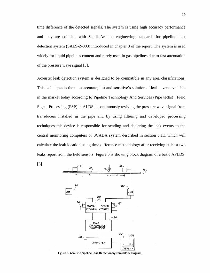
Acoustic leak detection system is designed to be compatible in any area classifications.
his techniques is the m st accurate, fast and sensitive’s s luti n f leaks event available
in the market today according to Pipeline Technology And Services (Pipe techs) . Field
Signal Processing (FSP) in ALDS is continuously reviving the pressure wave signal from
transducers installed in the pipe and by using filtering and developed processing
techniques this device is responsible for sending and declaring the leak events to the
central monitoring computers or SCADA system described in section 3.1.1 which will
calculate the leak location using time difference methodology after receiving at least two
leaks report from the field sensors. Figure 6 is showing block diagram of a basic APLDS.
[6]
Figure 6- Acoustic Pipeline Leak Detection System (block diagram)

20
4.3: System components:
4.3.1: Pressure Sensors:
Different types of pressure sensors with high sensitivity are used for detecting pressure
wave signals where the selection of these sensors are depending on the level of accuracy
and sensitive of the system, the classification area and the specifications of the pipe itself
such as its diameter , length and type of the pipe contents.
The sensor in figure 7 is provided by Pipe Techs company whereas the one in figure 8 is
provided by Acoustic System Incorporated (ASI) company which is the used sensor in
Saudi Aramco pipeline projects. They are responsible for data acquisition and
transmission of the pressure wave signals. Both sensors have the same technical
specification which are compatible with SAES. [6] [7]
Figure 8 - WIKA E10 E-11 pressure sensor Figure 7 - WIKA E10 E-10 pressure sensor

21
The following table is listing sensors features.
Table 3 - Pressure Sensors Spicifications
Table 3 shows the pressure sensors specification in pipeline projects for leak detection,
the voltage supplying will be feed up by FSP with the listed value. The span range means
that the two end sensors separation shall not be less than 80 meters. [6]
4.3.2: Field Signal Processing (FSP):
Field Signal Processing is powerful unit that is capable of monitoring real-time signal,
data acquisition and control processing. This component of the system should be
withstanding harsh environment conditions.
Figure 9 shows the FSP provided by the National Instrument Corporation (US-Based
facility). In the field, the FSP should be installed inside a cabinets which placed in field
equipment shelters.
Voltage Supply 10 – 30 V
Output signal Current signal: 4 – 20mA
Connection to FSP Two instrumentation cables
Sampling rate 1000 samples per seconds
Span range greater than 80 meters
Figure 9 - FSP

22
FSP operation
The FSP operation includes the following:
a- Data Acquisition
b- Electrical noise filtering
c- Pressure signal filtering
d- Communication
e- Time indicating
During losing of communication network, FSP will register all leaks event sorted in a
memory and then transmitted with a time indicator of each event to the control center as
soon as the network is back. It will read pressure signal at a sampling rate of 1ms after
passing the filtering level of analog and digital signals. Then, the signal will be averaged
to 20 readings per second and used to create a signal profile to compare it with mask
signal (original) to indicate the pressure wave leaks on it. Global Positioning system
(GPS) is used to synchronized al time stamping in the system to get more accurate
results. Moreover, in the absence of leaks events, a profile will be sent continuously to
the control center indicating the state of the pipe. [6]
WaveAlert field processor
WaveAlert field processor is an example of FSP that will be used to convert analog
signals to its digital form using A/D converters, create correlation profile and compare it
with threshold to perform the system test and using GPS for synchronization. This devise
is provided by ASI under the following specifications:
1) Standard input / outputs including 4-20 ma, dry contact relays, optically isolated
inputs
2) Robust, high reliability, industrial temperature design for in oil and gas industry
3) Low maintenance
4) Easy installation
5) Easy replacement
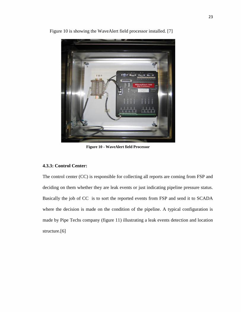
23
Figure 10 is showing the WaveAlert field processor installed. [7]
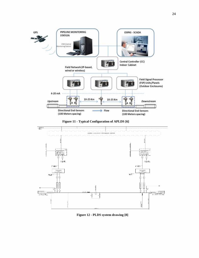
4.3.3: Control Center:
The control center (CC) is responsible for collecting all reports are coming from FSP and
deciding on them whether they are leak events or just indicating pipeline pressure status.
Basically the job of CC is to sort the reported events from FSP and send it to SCADA
where the decision is made on the condition of the pipeline. A typical configuration is
made by Pipe Techs company (figure 11) illustrating a leak events detection and location
structure.[6]
Figure 10 - WaveAlert field Processor
24
Figure 11 - Typical Configuration of APLDS [6]
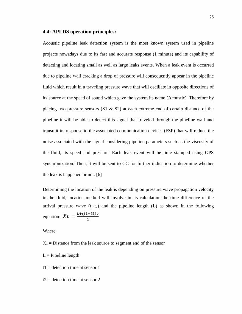
Figure 12 - PLDS system drawing [8]
25
4.4: APLDS operation principles:
Acoustic pipeline leak detection system is the most known system used in pipeline
projects nowadays due to its fast and accurate response (1 minute) and its capability of
detecting and locating small as well as large leaks events. When a leak event is occurred
due to pipeline wall cracking a drop of pressure will consequently appear in the pipeline
fluid which result in a traveling pressure wave that will oscillate in opposite directions of
its source at the speed of sound which gave the system its name (Acoustic). Therefore by
placing two pressure sensors (S1 & S2) at each extreme end of certain distance of the
pipeline it will be able to detect this signal that traveled through the pipeline wall and
transmit its response to the associated communication devices (FSP) that will reduce the
noise associated with the signal considering pipeline parameters such as the viscosity of
the fluid, its speed and pressure. Each leak event will be time stamped using GPS
synchronization. Then, it will be sent to CC for further indication to determine whether
the leak is happened or not. [6]
Determining the location of the leak is depending on pressure wave propagation velocity
in the fluid, location method will involve in its calculation the time difference of the
arrival pressure wave (t1-t2) and the pipeline length (L) as shown in the following
equation:
Where:
Xv = Distance from the leak source to segment end of the sensor
L = Pipeline length
t1 = detection time at sensor 1
t2 = detection time at sensor 2
26
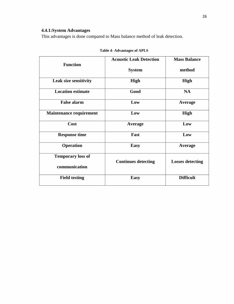
4.4.1:System Advantages
This advantages is done compared to Mass balance method of leak detection.
Table 4- Advantages of APLS
Function
Acoustic Leak Detection
System
Mass Balance
method
Leak size sensitivity High High
Location estimate Good NA
False alarm Low Average
Maintenance requirement Low High
Cost Average Low
Response time Fast Low
Operation Easy Average
Temporary loss of
communication
Continues detecting Losses detecting
Field testing Easy Difficult
27
Chapter 5: Case Study II: Fiber Optic Sensing in Pipeline
Projects:
5.1: Introduction:
Pipeline can often face hazardous cases to the environment since they contains hazardous
material such as gas or oil. That pipeline failure can cause economic and environmental
damage. Furthermore, the pipeline itself can face problem such as corrosion, erosion and
fatigue due to that failure. Therefore it bring a serious challenge to face that huge
consequences before they happened by finding the right solution to detect any leak in a
pipeline, locate it and even stop it.
In the second case study another method of detecting leaks in pipeline networks will be
introduced and described in details. The method is using linear fiber optics which will
detect the leak depending on the temperature varying on temperature profile of the pipe
wall over long distance when a leak is occurring. This method is very useful over other
methods of detecting the leak when the goal is to detect and locate the leak over long
distances reaching to 50KM pipeline network. When it comes to Kilometric pipeline
length it become highly cost affected and almost impossible to use the discreet sensing
such as Acoustic leak detection due to the large number of sensors is going to be installed
and the complex data acquisition will be used.
28
5.2: Distributed Temperature Sensing:
It is an optoelectronic system measure temperature by means of optical fibers working as
linear sensors. Rather than detecting at a single point, temperature is measured through a
fiber optical cable which will lead to a higher accuracy of detecting over long distance
pipelines. The temperature will affect the fiber glass changing the light transmission
characteristic in the fibers. As a result of that, the external physical parameters
(temperature) that changing the fibers characteristics can be localized which means that
fiber optics is going to be working as linear sensors. [8]
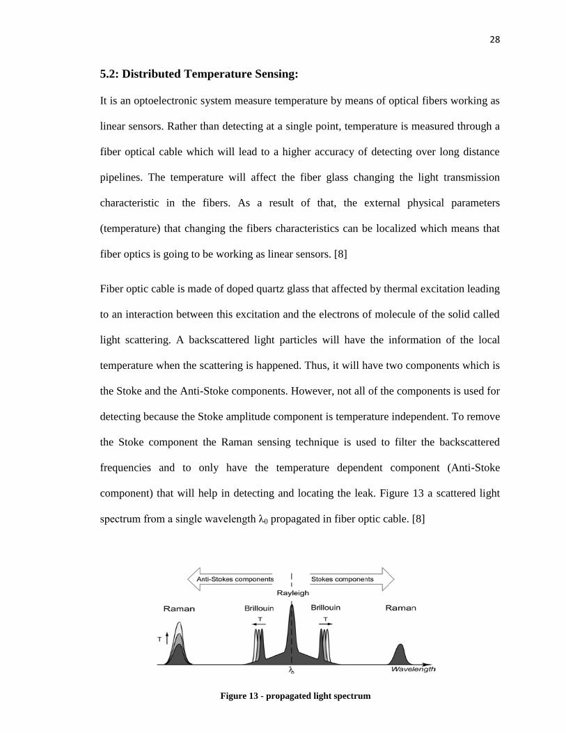
Fiber optic cable is made of doped quartz glass that affected by thermal excitation leading
to an interaction between this excitation and the electrons of molecule of the solid called
light scattering. A backscattered light particles will have the information of the local
temperature when the scattering is happened. Thus, it will have two components which is
the Stoke and the Anti-Stoke components. However, not all of the components is used for
detecting because the Stoke amplitude component is temperature independent. To remove
the Stoke component the Raman sensing technique is used to filter the backscattered
frequencies and to only have the temperature dependent component (Anti-Stoke
component) that will help in detecting and locating the leak. Figure 13 a scattered light
spectrum fr m a single wavelength λ0 propagated in fiber optic cable. [8]
Figure 13 - propagated light spectrum

29
5.3: DTS components:
components of temperature measurement system include a controller that consist of a
high frequency mixer, laser source, optical module, micro-processor unit and a receiver.
Moreover, line-shaped fiber optic cable made out from quartz glass to function as
temperature sensors. Noticing that the system has a few components that can be
implemented over a large area as shown in figure 14, the system has an advantage over
other detecting system. Fiber optics system has no moving parts which is considered to
be easier in operation and maintenance. Moreover, as it is linear-shaped cables it is more
convenient to use it for long distance pipelines. Also these cables have high immunity to
electromagnetic waves distortion which will decrease interfering signals with background
noise dramatically. It is a passive system have no active electronics component along the
cables, used in hazardous areas safely and have high reliability over long terms. [8]
Figure 14- DTS basic components

30
Fiber optic sensors (Technical specifications):
Table 5- Fiber Optic Sensor (Tech. Spec.)
Measurement Range Up to 30 km, 100 km using range extenders
Temperature
Measurement Range -220°C to +500°C
Temperature Resolution 0.1 °C
Temperature Accuracy ±1 °C
Power Supply 115 or 235 VAC, max. 400 W
Operating Temperature 0 to +40°C
In Table 5, a sample product of fiber optic sensors is examined and providing its
technical information. This sensor characteristic is provided by Environmental System
and Services.

31
5.4: Principle of operation:
Fiber optics sables should be positioned along the pipeline length and a source of light
such as laser beams or Light Emitting diodes (LEDs) is injected through the cables. The
lighting beam will be scattered in the fibers and Raman Stoke and Anti-Stoke
components will be appeared and measured when it returns to the emitting source
originally. Raman technique of measurement depend on the intensity of the light which is
related to the temperature of the optical medium. The relationship of measuring the
temperature in optical fiber is given in the following equation. [10]
Where :
vo : Wave number of incident light
vk: Wave number shift of material
h: lanck’s c nstant
k: Boltzmann's constant
c : speed of light in optical fiber
T absolute temperature
Ia : intensity of anti-Stokes light
Is intensity of Stokes light
Measuring the intensity of Raman scattered wave will lead the fiber optic sensor to
measure the temperature in the portion where the light scattered. Therefore, this
technique is used for detecting leaks in pipeline by measuring the temperature changed
due to the leak. [10]
32
Temperature will be sensed by optical fibers not only in a certain point but in continues
line working as linear sensors which will reflect the pipeline profile. As long as the
distance of the pipe is increased a high accuracy of sensing will be reached.
5.4.1: Leakage detection:
Leakage detection using fiber optic distributed temperature mentoring can either detect
local warming in the pipe or cooling in I depending in the type of product transported in
the pipeline. For example:
Gas expansion lead to cooling temperature variation.
Liquid content ( crude oil ) or heating system will lead to warming variation
In both cases the fiber optic system will sense the action and that change will be affected
the general profile of the pipeline. Furthermore, due to the geometry of the fiber optic and
its low propagation loss characteristic monitoring pipe leakage will be excellent for a
long distance. [9]
Localizing Temperature Change:
To localize temperature changing two factors of measurement can be considered. The
first is the space or few meters around the leak event. Secondly, time of the leak event is
included to localize a certain leak event. [9]
33
Environment temperature and actual leak temperature:
Problem Description:
how does fiber optic systems discriminate between actual leakage temperature and
environmental temperature varying?
Solution:
fiber optic system should work relative to the no leak status. For example, the system
will measure the temperature profile in the no leak event and over the time if there is a
notable change in the envelope of the profile with certain increase in the temperature,
then it is leakage status.
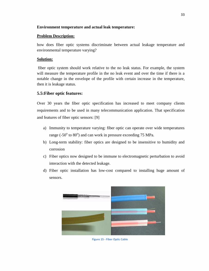
5.5:Fiber optic features:
Over 30 years the fiber optic specification has increased to meet company clients
requirements and to be used in many telecommunication application. That specification
and features of fiber optic sensors: [9]
a) Immunity to temperature varying: fiber optic can operate over wide temperatures
range (-50o to 80
o) and can work in pressure exceeding 75 MPa.
b) Long-term stability: fiber optics are designed to be insensitive to humidity and
corrosion
c) Fiber optics now designed to be immune to electromagnetic perturbation to avoid
interaction with the detected leakage.
d) Fiber optic installation has low-cost compared to installing huge amount of
sensors.
Figure 15 - Fiber Optic Cable

34
5.6:Fiber Optics Positioning:
A fiber optic should be placed in the right position to sustain accurate leakage detection.
For a buried pipeline, the proper place to position the cables is under the pipe and not in
direct contact to the pipe as shown in figure 16. This is to collect as much as possible of
the leaking oil independently of its location. Additionally, for a pipeline installed under
the water, when a leakage happen the oil will tend to flow directed up, in this case the
cable position is reversed.
As mentioned in section 5.4.1 that gas expansion would cool the pipeline and its
surroundings, so in this case the best position is to put the cables in direct contact with
pipeline as shown in figure 17
Figure 16 - Cables positioning for buried pipeline
Figure 17 - cable positioning when pipe contains gas
35
Conclusions & Recommendations:
Pipelines recently are the safest method to delivering gas and crude oil. Therefore the risk
must be handled to avoid loss of life, environmental contamination and costly shutdown.
The future goal of pipeline leak detection system is to improve new technologies to gain
more accurate leak alarm and location maintaining the proper techniques used for
detecting and locating leaks in pipeline projects.
The Training experience was very helpful to gain such information about pipeline leak
detection system techniques I have discussed two of them. The first discussion was my
first case study which is a real system implemented and installed in some Sarudi Armaco
pipeline projects. I have learned how the system is working and how are instrumentation
engineers have to think when the handle such projects considering that all parameters and
features of the system including its cost and long term maintenance and operation. The
second discussion includes the fiber optic sensing case study which is a widely studied
topic and is being processes trying to improve its features more so it may replace the
acoustic method in pipeline projects especially in term of cost effectiveness compared
between the two topics.
During my training with Project Management Team, I have gained useful skill that may
help in future job such as how to communicate with different sections and departments in
the organization during such team projects, to be punctual at work and avoiding any
delay of tasks to avoid its circumstances. Also, this opportunity gave me the chance to
see real applications of my major during our site visits such small circuit breakers used

36
for ensure the safety in supplied power for pipeline projects and how to do circuit
troubleshooting in electrical circuits that can be applied in my future job.

37
References [1] Saudi Aramco. Engineering Procedure (SAEP-747). Pipeline leak detection
system.4 March 2014
[2] Saudi Aramco. Engineering Standards (SAES-Z-003). Pipeline leak detection
system. 28 August 2013
[3] Maurino De Febbo, R&D Manager, Asel-Tech Inc., Houston, TX, USA. A new
generation of leak-detection systems for pipelines. March 2013. Retrieved from
Pipelines International
[4] Technical Review of Leak Detection Technologies. Volume I. Crude oil
transmission pipelines. Retrieved from Alaska Department of Environmental
Conservation
[5] Prof. Dr.-Ing. Gerhard Geiger. Principle of leak detection. Retrieved from
KROHNE Oil & Gas
[6] Pipeline Technologies & Services. Company products. Retrieved from
http://www.pipetechs.com
[7] Acoustic System Incorporated. Detect pipeline leaks at the speed of sound.
Retrieved from http://www.wavealert.com/
[8] Ashim Mishra, Ashwani Soni. (2011). Leakage Detection using Fiber Optics
Distributed Temperature Sensing
[9] O.lida, D.Onoda, S.Kono. Expansion of Measuring Range for a Fiber-optic
Distributed Temperature Sensors Applications to Commercial Plants.

38
APPENDIX A
- GLOSSARY:
Area of interest: A specific operational, engineering, performance of maintenance or
economical feature of a PLDS product which can potentially benefit Saudi Aramco.
Pipeline Types: The type of the pipeline is determined by the type of fluid flowing in the
line.
Leak Location Method: A process including measuring and processing of pipeline
variables which will indicated the location of a leak.
Leak Event: when leak occur physically.
Leak wave: A sudden leak will create a dynamic wave.
Pressure wave detection: It is a leak detection method depends on measuring and
processing leak waves signals developed from pipeline leak.
Pressure wave location: a method of determining the leak location by finding the travel
time of a leak wave from its source to a known location point of measurement. The wave
velocity is approximately within the speed of sound.
Sensitivity Study: it a study to indicate the level of sensitivity, reliability, accuracy and
robustness for pre-determined performance selection and installing conditions.
Workstation: Group of PCs associated with monitors screen, keyboards and other
peripheral devices used to interface with human machine for maintenance and
engineering functions

39
Networked Pipelines: Highly integrated transmission and distribution grids to transport
products.
Background Noise (Nuisance): an unwanted measured signal that affect the
performance of measurements. These signals are created by non-leak sources (e.g.,
environment conditions, pipeline operating conditions such as pumps, compressors,
flares, etc.).
Creeping leak: pipeline leak that are developed gradually due to localized corrosion or
pipe wall cracking.
Data collection device (field processor): collecting and processing different
measurements and sending data to other components of pipeline leak detection system for
detecting and locating leak process.
Hydrocarbon: organic compound consist of hydrogen and carbon. It is naturally found
in crude oil.
40
APPENDIX B
Figure 18 - Training Plan_page1

41
Figure 19- Training Plan_page2
42
APPENDIX C
Table 6- Location Classes 1
Performance
Measure
Service
G GS L LS LV LVS
Reliability Low Low Low Low Low Low
Sensitivity Low Low Low Low Low Low
Accuracy Low Low Low Low Low Low
Robustness Low Low Low Low Low Low
Table 7 - Location Classes 2
Performance
Measure
Service
G GS L LS LV LVS
Reliability Low Medium Low Medium Low Medium
Sensitivity Low Medium Low Medium Low Medium
Accuracy Low Medium Low Medium Low Medium
Robustness Low Medium Low Medium Low Medium
Table 8 - Location Classes 3
Performance
Measure
Service
G GS L LS LV LVS
Reliability Medium High Medium High Medium High
Sensitivity Medium High Medium High Medium High
Accuracy Medium High Medium High Medium High
Robustness Medium High Medium High Medium High
Table 9 - Location Classes 4
Performance
Measure
Service
G GS L LS LV LVS
Reliability High High Medium High Medium High
Sensitivity High High Medium High Medium High
Accuracy High High Medium High Medium High
Robustness High High Medium High Medium High

43
APPENDIX C
Class Definition:
Class 1: locations that its population density index within any 1 Kilometer is 10 or less
Class 2: locations which its population density index is 11 through 30 or crossing
secondary highways.
Class 3: locations that its population density index is more than 30.
Class 4: Locations including hospitals, school, hotel or prison or similar areas.
Terminologies:
G Sweet gas (treated gas)
GS Sour gas (gas concentration Hydrogen Sulfide (H2S > 1%)
L sweet liquid (stabilized crude < 300 ppm H2S)
LS Sour liquid (Untreated Hydrocarbon) > 300 ppm H2S
LV Volatile sweet liquids < 300 ppm H2S
LVS Volatile sour liquids > 300 ppm H2S
PPM: Part Per Million. Scaling can be by saying 1 ppm is like 1 inch in 16 miles.
44
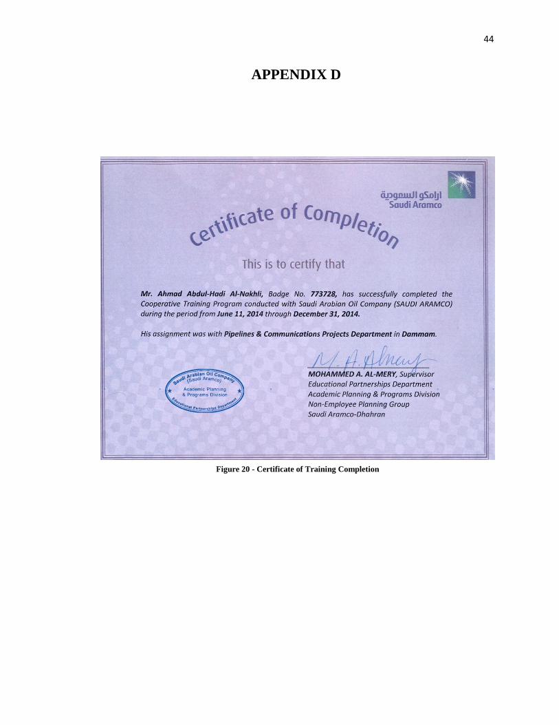
APPENDIX D
Figure 20 - Certificate of Training Completion