final construction plansrepublicconstructioncorp.com/wp-content/uploads/2016/10/complete... ·...
TRANSCRIPT

CAROLTON LN
VO
LU
NT
EE
R R
D
TH
OR
OU
GH
BR
ED
LN
SW 57TH ST
SW
168T
H A
VE
SW
170T
H A
VE
SW 37TH ST
SW 38TH ST
S
W
3
8
T
H
S
T
SUNSET DRSW 51ST ST
SW 56TH ST
W PALOMINO DR
E
M
E
R
A
L
D
E
S
T
A
T
E
S
D
R
RU
BY
LK
HE
RO
N R
IDG
E L
N
SW 41ST ST
RUBY LAKE
N S
AX
ON
CIR
SA
XO
N C
IR N
SA
XO
N C
IR S
S S
AX
ON
CIR
C
AS
TLE
G
AT
E A
VE
C
A
S
T
L
E
G
A
T
E
A
V
E
BERKSHIRE CT
STRATFORD CT
F
A
L
C
O
N
S
L
E
A
D
R
W
W
F
A
L
C
O
N
S
L
E
A
D
R
SW 61ST ST
SW 59TH ST
P
O
IN
T
E
W
E
S
T
D
R
HA
WK
HU
RS
T A
VE
E
W
A
T
E
R
F
O
R
D
D
R
SW 52ND PL
SW 53RD CT
SW
167T
H A
VE
SW 61ST PL
W S
AX
ON
C
IR
SA
XO
N C
IR
W
SW
151S
T A
VE
S
W
1
5
1
S
T
A
V
E
S
A
N
D
Y
R
I
D
G
E
D
R
WE
ST
C
IT
Y D
R
K
I
N
G
A
R
T
H
U
R
A
V
E
LA
NC
ELO
T LN
SW 47TH CT
SAPPHIRE S
T
GR
EE
N M
EA
DO
WS
D
R
D
U
R
H
A
M
L
N
P
A
L
M
P
L
B
R
I
S
T
O
L
L
N
AS
CO
T T
ER
VIS
TA
W
AY
R
IC
K
C
A
S
E
H
O
N
D
A
W
A
Y
SU
RR
EY
CIR
W W
AT
ER
FO
RD
D
R
S
A
P
P
H
I
R
E
D
R
T
U
R
Q
U
O
IS
E
T
R
L
S
T
A
G
H
O
R
N
L
N
S
U
P
E
R
IO
R
B
LV
D
NORFOLK LN
DERBY CT
SO
ME
RS
ET
LN
DIAMOND PL
DIA
MO
ND
PL
SW 49TH CT
N
IG
H
T
H
A
W
K
D
R
A
M
B
E
R
L
N
SW
173R
D W
AY
SW
173R
D W
AY
SW 53RD ST
W
A
T
E
R
F
O
R
D
D
R
S
S
W
A
T
E
R
F
O
R
D
D
R
SA
N S
IM
EO
N C
IR
B
R
I
G
H
T
O
N
L
N
M
E
A
D
H
A
V
E
N
S
T
P
I
N
E
R
I
D
G
E
L
N
SW 51ST MNR
SW 51ST MNR
S
W
51S
T
M
N
R
M
A
G
N
O
L
IA
R
ID
G
E
D
R
F
O
X
R
I
D
G
E
D
R
S
A
P
P
H
I
R
E
P
L
BELLA DR
S
A
P
P
H
I
R
E
T
E
R
D
I
A
M
O
N
D
D
R
AM
BE
R W
AY
SW
161S
T A
VE
Q
U
E
E
N
L
A
K
E
T
E
R
G
R
A
P
E
V
IN
E
W
A
Y
D
O
G
W
O
O
D
C
I
R
SA
PP
HIR
E IS
LE
AMBER LK
T
A
T
E
N
S
H
A
L
L
T
R
L
O
S
P
R
E
Y
C
T
FO
X H
OLW
AMBER
BAY DR
YO
RK
LN
DIA
MO
ND
HE
AD
DR
M
A
N
C
H
E
S
T
E
R
L
N
F
A
L
C
O
N
R
ID
G
E
C
IR
C
R
O
S
S
B
IL
L
L
N
R
O
U
N
D
T
A
B
L
E
R
D
E
E
R
O
U
N
D
T
A
B
L
E
R
D
P
L
Y
M
O
U
T
H
L
N
L
E
E
D
S
L
N
S
A
P
P
H
I
R
E
B
N
D
W S
UR
RE
Y C
IR
SA
PP
HIR
E LK
S
A
N
S
I
M
E
O
N
L
N
SA
PP
HIR
E LN
G
R
E
E
N
B
R
I
A
R
L
N
S
A
N
D
E
R
L
I
N
G
L
N
B
R
IA
R
W
O
O
D
W
A
Y
BR
IAR
W
O
O
D M
NR
G
R
E
E
N
B
R
I
A
R
L
N
EP
SO
M LN
P
I
N
E
R
I
D
G
E
C
T
DE
VO
N LN
R
O
U
N
D
T
A
B
L
E
R
D
SU
RR
EY
C
IR
E
F
O
X
H
E
A
T
H
D
R
SW
159T
H A
VE
C
IN
N
A
M
O
N
W
A
Y
S
W
1
5
3
R
D
A
V
E
L
A
U
R
E
L
R
I
D
G
E
C
I
R
W
I
N
D
O
V
E
R
W
A
Y
N
E
W
C
A
S
T
L
E
L
N
DIA
MO
ND
W
AY
AMBER LAKE
H
A
W
K
S
C
T
S
A
B
A
L
R
ID
G
E
C
IR
ONEIDA PL
M
A
H
O
G
A
N
Y
R
I
D
G
E
D
R
R
O
U
N
D
T
A
B
L
E
R
D
S
S
A
P
P
H
IR
E
C
O
V
E
SAPPHIRE CT
T
H
O
R
N
B
L
U
F
F
A
V
E
TH
IS
TLE
DO
WN
T
ER
P
I
N
E
R
I
D
G
E
D
R
LA
NC
ELO
T C
T
CAR
RIA
GE C
T
C
O
N
D
O
R
C
T
W
I
N
K
F
I
E
L
D
W
A
Y
SEDGEWYCK CIR NN SEDGEWYCK CIR
CH
ES
TE
R LN
D
IA
M
O
N
D
R
O
W
T
U
R
N
S
T
O
N
E
C
T
C
A
N
T
E
R
B
U
R
Y
C
T
MA
RT
IN
C
T
C
R
E
S
T
W
O
O
D
C
I
R
SW
IN
DE
N LN
RAVENSWICKE MNR
CO
BB
LE
ST
ON
E C
T
CO
RN
W
ALL LN
P
O
R
T
S
M
O
U
T
H
L
N
DIA
MO
ND
P
OIN
T LN
V
IL
L
A
G
E
D
R
DIA
MO
ND
P
OIN
TE
LN
SW
149T
H A
VE
W
H
E
T
S
T
O
N
E
W
A
Y
K
N
I
G
H
T
H
U
R
S
T
W
A
Y
O
S
P
R
E
Y
D
R
EMERALD WAY
RA
VE
NS
W
IC
KE
T
ER
CA
RR
IA
GE
LN
SAPPHIRE SPRINGS
SW
160T
H T
ER
F
O
X
R
U
N
C
T
W
A
T
E
R
M
I
L
L
R
D
D
I
A
M
O
N
D
C
A
Y
SW
158T
H W
AY
E
A
G
L
E
C
T
CAYUGA CIR
NW 61ST ST
SENECA CIR
E
M
E
R
A
L
D
C
O
V
E
R
D
S
TO
N
E
R
ID
G
E
W
A
Y
CO
BB
LE
ST
ON
E LN
B
L
O
S
S
O
M
L
N
O
P
A
L
C
R
E
E
K
D
R
BE
EC
HW
OO
D C
IR
B
O
S
T
O
N
C
T
SAPPHIRE MNR
L
A
U
R
E
L
R
I
D
G
E
D
R
S
W
1
5
3
R
D
T
E
R
SW
149T
H T
ER
C
L
O
V
E
R
D
A
L
E
C
T
H
E
R
O
N
R
ID
G
E
D
R
S
A
N
S
IM
E
O
N
D
R
S
W
1
5
0
T
H
W
A
Y
E
A
G
L
E
B
R
O
O
K
C
T
F
O
X
G
L
O
V
E
L
N
SW
148T
H T
ER
L
A
N
C
E
P
O
I
N
T
P
L
F
O
X
G
L
O
V
E
L
N
P
I
N
E
C
R
E
S
T
C
T
C
H
I
L
L
I
N
G
S
W
O
R
T
H
C
T
W
I
N
K
F
I
E
L
D
C
I
R
G
R
I
F
F
I
N
R
D
R
A
M
P
SW 62ND ST
SW
142N
D A
VE
SW 50TH CT
SW 48TH ST
G
R
I
F
F
I
N
R
D
R
A
M
P
AC
CE
SS
RD
SW 49TH ST
E
M
E
R
A
L
D
P
A
R
K
C
I
R
SW 54TH PL
EMERALD PARK CIR
SW 59TH CT
S
W
5
1
S
T
S
T
SW 40TH ST
SW 54TH PL
SW
49T
H S
T
SW 48TH ST
SW 62ND ST
SW 61ST CT
GR
IF
FIN
R
D
SW 39TH ST
SW
160T
H A
VE
I
7
5
R
A
M
P
SW 51ST ST
SW 61ST CT
S
W
5
1
S
T
C
T
AC
CE
SS
R
D
A
C
C
E
S
S
R
D
SW 49TH ST
G
R
IF
F
IN
R
D
R
A
M
P
SW 45TH ST
STIRLING RD
S POST RD
SW 60TH ST
WE
ST
ON
R
D
HA
NC
OC
K R
D
SW
154T
H A
VE
SW
160T
H A
VE
SW
172N
D A
VE
SW
178T
H A
VE
SW
166T
H A
VE
DY
KE
S R
D
BO
Y S
CO
UT
R
D
SW
163R
D A
VE
SW
164T
H T
ER
SW 58TH ST
SW 49TH ST
SW 52ND CT
SW
145T
H A
VE
SW
162N
D A
VE
SW
148T
H A
VE
VO
LU
NT
EE
R R
D
SW 54TH ST
SW 59TH CT
SW 48TH ST
SW 46TH ST
GR
IF
FIN
R
D R
AM
P
N
R
I
D
G
E
D
R
SW 61ST CT
SW 56TH ST
E
M
E
R
A
LD
P
A
R
K
C
IR
HUNTRIDGE RD
P
O
N
D
R
I
D
G
E
C
I
R
C
AS
TLE
G
AT
E A
VE
LAKE LN
SW 61ST ST
MARVIN LN
SW
150T
H A
VE
WINDSOR BLVD
DOVER CT
DIA
MO
ND
T
ER
PEDIGREE LN
I
7
5
R
A
M
P
SW 54TH ST
ACCESS RD
SW 50TH ST
SW 45TH ST
SW
148T
H A
VE
SW 41ST ST
SW 49TH ST
SW 61ST CT
S POST RD
GRIFFIN RD
STIRLING RD
I-75
3132
3029
3334
2827
ThoroughbredLane Headwalls
FINAL CONSTRUCTION PLANS
FOR
CALUSA CORNERS PARK IMPROVEMENTS
TOWN OF SOUTHWEST RANCHES, BROWARD COUNTY, FLORIDA
PREPARED FOR:
TOWN OF SOUTHWEST RANCHES
13400 GRIFFIN ROAD
SOUTHWEST RANCHES, FL 33330
VICINITY MAP
CALUSA CORNERS
PARK
PROJECT No. 08711.07 09/10/15
301 East Atlantic Boulevard
Pompano Beach, Florida 33060-6643
(954) 788-3400; FAX (954) 788-3500
State of Florida Certificate of
Authorization Number - 7928THESE PLANS MAY HAVE BEEN
REDUCED IN SIZE BY REPRODUCTION.
THIS MUST BE CONSIDERED WHEN
OBTAINING SCALED DATA.
W. Palm
Beach
Fort
Lauderdale
F
L
O
R
I
D
A
Key West
Tallahassee
Pensacola
Orlando
Rockledge
Tampa
St. Petersburg
Miami
Daytona Beach
Gainesville
St. Augustine
Jacksonville
TOWN OF SOUTHWEST RANCHES
BROWARD COUNTY
ALL ELEVATIONS SHOWN ON THESE PLANS
ARE BASED ON NAVD 1988 DATUM
DIFFERENCE
+1.64 FEET
ELEV.
1.64'
0.00'
DATUM
NGVD 1929
NAVD 1988
FEMA EL. - ZONE AH (EL. 6) AND
ZONE AH (EL. 5)
S 33, T 50S, R 40E

GI-001
05/01/15
NT
S
MG
MG
SW
LE
GE
ND
1
D
2 3
C
4 5
A
B
SHEET
IDENTIFICATION
DA
TE
PROJECT NO.
DA
TE
:
SC
ALE
:
DR
AW
N B
Y:
DE
SIG
N B
Y:
CH
EC
KE
D B
Y:
RE
VIS
IO
N
CA
LU
SA
C
OR
NE
RS
PA
RK
IM
PR
OV
EM
EN
TS
08711.07
TO
WN
o
f S
OU
TH
WE
ST
R
AN
CH
ES
B
RO
WA
RD
C
OU
NT
Y
301 E
ast A
tlantic B
oulevard
Pom
pano B
each, F
lorida 33060-6643
(954) 788-3400; F
AX
(954) 788-3500
State of F
lorida C
ertificate of
Authorization N
um
ber - 7928
Dra
win
g n
am
e: N
:\0
8'\0
87
11
.0
7 C
alu
sa
C
orn
ers P
ark - S
W R
an
ch
es\E
ng
in
ee
rin
g\C
ad
d\C
on
stru
ctio
n D
ra
win
gs\0
87
11
.0
7-G
I-0
XX
.d
wg
L
ayo
ut N
am
e: G
I-0
01
P
lo
tte
d b
y: m
grin
ba
nk P
lo
tte
d o
n: D
ec 1
4, 2
01
5 - 1
0:3
8a
m
Dra
win
g n
am
e: N
:\0
8'\0
87
11
.0
7 C
alu
sa
C
orn
ers P
ark - S
W R
an
ch
es\E
ng
in
ee
rin
g\C
ad
d\C
on
stru
ctio
n D
ra
win
gs\0
87
11
.0
7-G
I-0
XX
.d
wg
L
ayo
ut N
am
e: G
I-0
01
P
lo
tte
d b
y: m
grin
ba
nk P
lo
tte
d o
n: D
ec 1
4, 2
01
5 - 1
0:3
8a
m
SHEET
(F
OR
T
HE
F
IR
M)
ST
EP
HE
N D
. W
ILLIA
MS
, P
.E
.
FLO
RID
A R
EG
. N
O. 32090
General Symbols
Existing Proposed Description
Centerline & Baseline of Survey or Construction
Building Access (ADA)
Building Access (NON-ADA)
Driveway Turnout Identification (Per FDOT Index 515) w/
Drive Width
Sidewalk Curb Ramp (Per FDOT Index 304)
Proposed Section Marker
Flag Pole
GPS Point
Hay Bales
Mail Box
Major Contour Elevation
Minor Contour Elevation
Parking Meter
Property Line
Grade Elevation
Top Of Curb Elevation/Pavement Elevation
Soil Test Boring Hole
Survey Bench Mark
Line Types
Existing Proposed Description
County Bound
Demolition Line
Easement Line
Property Line
Limited Access Line/Non-Vehicular Access
Railroad
Right Of Way
Canal Or Drainage Ditch
Shore Line
Tree Line
Aerial Communication Line
Underground Communication Line
Underground Storm Drain Line (Double Line 24" And Over
Underground Sanitary Line
Aerial Electric Line
Underground Electric
Underground Water Line
Underground Force Main
Gate
Chain Link Fence
Wood Fence
Metal Rail Fence
Silt Fence
Staked Turbidity Barrier
Turbidity Barrier
Guard Rail
Roadway Centerline
2 - 4 Skip
3 - 9 Skip
6- 10 Skip
10 - 30 Skip
10 - 10 - 20 Skip
Curb
Curb And Gutter
Landscaping
Existing Proposed
Description
Bush
Tree
Palm Tree
Paving and Grading
Existing Proposed Description
Flow Directional Arrow
Pavement Marking Arrows
Stop Bar
Concrete Sidewalk
Jogging Path
Pavement Area
Existing Pavement/Concrete/ Landscape Removal Area
Milling And Resurfacing
Detectable Warning (Truncated Domes) Per Florida
Accessibility Code
Soil Tracking Prevention Device
Drainage / Utilities
Existing Proposed Description
Catch Basin
Yard Drain
Exfiltration Trench
` Catch Basin With Filter Fabric Insert
Curb Type 5
Curb Type 6
Pipe Culvert - Mitered End Section
Pipe Culvert - Straight Endwall
Pipe Culvert - U - Type Endwall
Manhole - Communication, Electric, Gas, Drn, San Sew
Valve Box - Gas, `San. Sew, Water, Non-Potable Water
22.5 degree Bend
45 degree Bend
90 degree Bend
Utility Crossing
Fire Hydrant
Proposed Bacteriological Sampling Point
Pump Station
Grease Trap
Septic Tank
Drainage Well
Monitoring Well
Water Well
Sanitary Sewer Cleanout
Back Flow Preventor
Junction Box
Electric Handhole
Electric Meter
Water Meter
Gate Valve
Guy wire
Light Pole
Relocated Or Adjusted Light Pole
Wood Power Pole
Concrete Utility Pole
Traffic Signal Pole (Concrete, Wood, Metal)
Pedestrian Signal Head (Pole Or Pedestal Mounted)
Post Mounted Sign
Street Sign
High Mast Lighting Tower
Controller Cabinet (Base Mounted)
Controller Cabinet (Pole Mounted)
Traffic Signal Head (Span Wire Mounted)
Traffic Signal Head (Pedestal Mounted)
Traffic Signal Head (Mast Arm Mounted)
Abbreviations
General
AADT
Annual Average Daily Traffic
ABAN Abandon
ADJ
Adjust
APPROX.
Approximate
A.C.
Asphalt Concrete
ACCM PIPE
Asphalt Coated Corrugated Metal Pipe
BIT. Bituminous
BC Back Of Curb
BD. Bound
BL Baseline
BLDG
Building
BM Benchmark
BO
By Others
BOS
Bottom Of Slope
BR.
Bridge
CAP
Corrugated Aluminum Pipe
CB Catch Basin
CBCI Catch Basin With Curb Inlet
CC Cement Concrete
CCM
Cement Concrete Masonry
CEM Cement
CI Curb Inlet
CIP
Cast Iron Pipe
CLF Chain Link Fence
CL Centerline
CMP
Corrugated Metal Pipe
CO.
County
CONC Concrete
CONT Continuous
CONST Construction
CR GR Crown Grade
DHV
Design Hourly Volume
DI
Drop Inlet
DIA Diameter
DIP
Ductile Iron Pipe
DWY
Driveway
ELEV (OR EL.)
Elevation
EMB Embankment
EOP
Edge Of Pavement
EXIST (OR EX) Existing
EXC Excavation
F&C Frame And Cover
F&G Frame And Grate
FDN. Foundation
FLDSTN Fieldstone
GAR
Garage
GD Ground
GI Gutter Inlet
GIP
Galvanized Iron Pipe
GRAN Granite
GRAV Gravel
GRD Guard
GV Gate Valve
HDW Headwall
HMA
Hot Mix Asphalt
HOR Horizontal
HYD
Hydrant
INV Invert
JCT Junction
L
Length Of Curve
LB Leach Basin
LP
Light Pole
LT Left
MAX Maximum
MB Mailbox
MH Manhole
MIN Minimum
NIC Not In Contract
NO. Number
PC Point Of Curvature
PCC
Point Of Compound Curvature
P.G.L. Profile Grade Line
Abbreviations ContinuedPI Point Of Intersection
POC Point On Curve
POT
Point On Tangent
PRC Point Of Reverse CurvaturePROJ ProjectPROP Proposed
PT Point Of TangencyPVC Point Of Vertical CurvaturePVI Point Of Vertical IntersectionPVT Point Of Vertical TangencyPVMT PavementPWW Paved Water WayR Radius Of CurvatureR&D Remove And Dispose
RCP Reinforced Concrete PipeRD RoadRDWY RoadwayREM RemoveRET RetainRET WALL Retaining Wall
ROW Right Of WayRR RailroadR&R Remove And ResetRT RightSHLD ShoulderSMH Sewer ManholeST StreetSTA StationSSD Stopping Sight DistanceSW SidewalkT Tangent Distance Of Curve/Truck %TAN TangentTEMP Temporary
TC Top Of CurbTOS Top Of Slope
TYP TypicalUP Utility PoleVAR VariesVERT VerticalVC Vertical CurveWCR Wheel Chair Ramp
WIP Wrought Iron Pipe
WM Water Meter/Water MainX-SECT Cross Section
Traffic SignalCAB. CabinetCCVE Closed Circuit Video Equipment
DW Steady Don't WalkFDW Flashing Don't Walk
FR Flashing Circular Red
FRL Flashing Red Left ArrowFRR Flashing Red Right Arrow
FY Flashing Circular Amber
FYL Flashing Amber Left ArrowFYR Flashing Amber Right ArrowG Steady Circular Green
GL Steady Green Left ArrowGR Steady Green Right ArrowGSL Steady Green Slash Left ArrowGSR Steady Green Slash Right Arrow
GV Steady Green Vertical ArrowOL OverlapPED PedestrianPTZ Pan, Tile, ZoomR Steady Circular Red
RL Steady Red Left Arrow
RR Steady Red Right Arrow
TR SIG Traffic SignalTSC Traffic Signal Conduit
W Steady WalkY Steady Circular Amber
YL Steady Amber Left Arrow
A-1
24' WIDE
A-1
24' WIDE
14.48
MB
MB
__
CC
x
CC
x
SDSD
x
SS
SS
x
EE
x
WW
x
FM
FM
x
X XX X
SFSF
_ _
CBCB
CB
CB
DWDW
COCO
EE
x
X
X-X
X XX X
PS
#
PS
#
GTGT
STST
14.48
14.98
02
N: 623025.4322
E: 850262.1786
Coordinate values shown on proposed improvements
are relative to the coordinate values indicated on the
Right-of-Way, property corners or reference monument
GI-002
05/01/15
NT
S
MG
MG
SW
CO
NS
TR
UC
TIO
N S
PE
CIF
IC
AT
IO
NS
1
D
2 3
C
4 5
A
B
SHEET
IDENTIFICATION
DA
TE
PROJECT NO.
DA
TE
:
SC
ALE
:
DR
AW
N B
Y:
DE
SIG
N B
Y:
CH
EC
KE
D B
Y:
RE
VIS
IO
N
CA
LU
SA
C
OR
NE
RS
PA
RK
IM
PR
OV
EM
EN
TS
08711.07
TO
WN
of S
OU
TH
WE
ST
R
AN
CH
ES
B
RO
WA
RD
C
OU
NT
Y
301 E
ast A
tlantic B
oulevard
Pom
pano B
each, F
lorida 33060-6643
(954) 788-3400; F
AX
(954) 788-3500
State of F
lorida C
ertificate of
Authorization N
um
ber - 7928
Dra
win
g n
am
e: N
:\0
8'\0
87
11
.0
7 C
alu
sa
C
orn
ers P
ark - S
W R
an
ch
es\E
ng
in
ee
rin
g\C
ad
d\C
on
stru
ctio
n D
ra
win
gs\0
87
11
.0
7-G
I-0
XX
.d
wg
L
ayo
ut N
am
e: G
I-0
02
P
lo
tte
d b
y: p
wrig
ht P
lo
tte
d o
n: S
ep
1
5, 2
01
6 - 4
:1
9p
m
Dra
win
g n
am
e: N
:\0
8'\0
87
11
.0
7 C
alu
sa
C
orn
ers P
ark - S
W R
an
ch
es\E
ng
in
ee
rin
g\C
ad
d\C
on
stru
ctio
n D
ra
win
gs\0
87
11
.0
7-G
I-0
XX
.d
wg
L
ayo
ut N
am
e: G
I-0
02
P
lo
tte
d b
y: p
wrig
ht P
lo
tte
d o
n: S
ep
1
5, 2
01
6 - 4
:1
9p
m
SHEET
(F
OR
T
HE
F
IR
M)
ST
EP
HE
N D
. W
IL
LIA
MS
, P
.E
.
FL
OR
ID
A R
EG
. N
O. 3
20
90
03
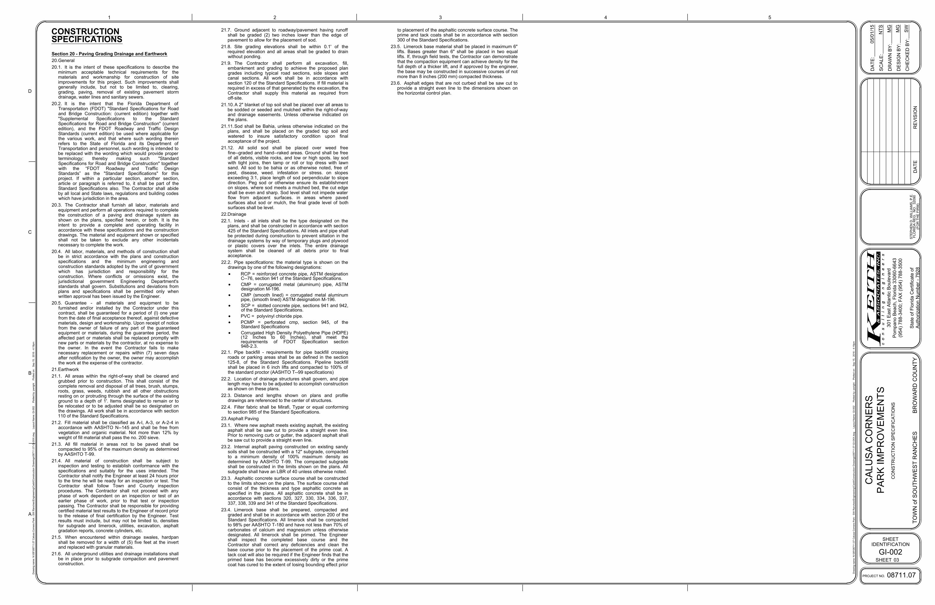
CONSTRUCTION
SPECIFICATIONS
Section 20 - Paving Grading Drainage and Earthwork
20.General
20.1. It is the intent of these specifications to describe the
minimum acceptable technical requirements for the
materials and workmanship for construction of site
improvements for this project. Such improvements shall
generally include, but not to be limited to, clearing,
grading, paving, removal of existing pavement storm
drainage, water lines and sanitary sewers.
20.2. It is the intent that the Florida Department of
Transportation (FDOT) "Standard Specifications for Road
and Bridge Construction: (current edition) together with
"Supplemental Specifications to the Standard
Specifications for Road and Bridge Construction" (current
edition), and the FDOT Roadway and Traffic Design
Standards (current edition) be used where applicable for
the various work, and that where such wording therein
refers to the State of Florida and its Department of
Transportation and personnel, such wording is intended to
be replaced with the wording which would provide proper
terminology; thereby making such "Standard
Specifications for Road and Bridge Construction" together
with the “FDOT Roadway and Traffic Design
Standards” as the "Standard Specifications" for this
project. If within a particular section, another section,
article or paragraph is referred to, it shall be part of the
Standard Specifications also. The Contractor shall abide
by all local and State laws, regulations and building codes
which have jurisdiction in the area.
20.3. The Contractor shall furnish all labor, materials and
equipment and perform all operations required to complete
the construction of a paving and drainage system as
shown on the plans, specified herein, or both. It is the
intent to provide a complete and operating facility in
accordance with these specifications and the construction
drawings. The material and equipment shown or specified
shall not be taken to exclude any other incidentals
necessary to complete the work.
20.4. All labor, materials, and methods of construction shall
be in strict accordance with the plans and construction
specifications and the minimum engineering and
construction standards adopted by the unit of government
which has jurisdiction and responsibility for the
construction. Where conflicts or omissions exist, the
jurisdictional government Engineering Department's
standards shall govern. Substitutions and deviations from
plans and specifications shall be permitted only when
written approval has been issued by the Engineer.
20.5. Guarantee - all materials and equipment to be
furnished and/or installed by the Contractor under this
contract, shall be guaranteed for a period of (l) one year
from the date of final acceptance thereof, against defective
materials, design and workmanship. Upon receipt of notice
from the owner of failure of any part of the guaranteed
equipment or materials, during the guarantee period, the
affected part or materials shall be replaced promptly with
new parts or materials by the contractor, at no expense to
the owner. In the event the Contractor fails to make
necessary replacement or repairs within (7) seven days
after notification by the owner, the owner may accomplish
the work at the expense of the contractor.
21.Earthwork
21.1. All areas within the right-of-way shall be cleared and
grubbed prior to construction. This shall consist of the
complete removal and disposal of all trees, brush, stumps,
roots, grass, weeds, rubbish and all other obstructions
resting on or protruding through the surface of the existing
ground to a depth of 1'. Items designated to remain or to
be relocated or to be adjusted shall be so designated on
the drawings. All work shall be in accordance with section
110 of the Standard Specifications.
21.2. Fill material shall be classified as A-l, A-3, or A-2-4 in
accordance with AASHTO N--145 and shall be free from
vegetation and organic material. Not more than 12% by
weight of fill material shall pass the no. 200 sieve.
21.3. All fill material in areas not to be paved shall be
compacted to 95% of the maximum density as determined
by AASHTO T-99.
21.4. All material of construction shall be subject to
inspection and testing to establish conformance with the
specifications and suitably for the uses intended. The
Contractor shall notify the Engineer at least 24 hours prior
to the time he will be ready for an inspection or test. The
Contractor shall follow Town and County inspection
procedures. The Contractor shall not proceed with any
phase of work dependent on an inspection or test of an
earlier phase of work, prior to that test or inspection
passing. The Contractor shall be responsible for providing
certified material test results to the Engineer of record prior
to the release of final certification by the Engineer. Test
results must include, but may not be limited to, densities
for subgrade and limerock, utilities, excavation, asphalt
gradation reports, concrete cylinders, etc.
21.5. When encountered within drainage swales, hardpan
shall be removed for a width of (5) five feet at the invert
and replaced with granular materials.
21.6. All underground utilities and drainage installations shall
be in place prior to subgrade compaction and pavement
construction.
21.7. Ground adjacent to roadway/pavement having runoff
shall be graded (2) two inches lower than the edge of
pavement to allow for the placement of sod.
21.8. Site grading elevations shall be within 0.1' of the
required elevation and all areas shall be graded to drain
without ponding.
21.9. The Contractor shall perform all excavation, fill,
embankment and grading to achieve the proposed plan
grades including typical road sections, side slopes and
canal sections. All work shall be in accordance with
section 120 of the Standard Specifications. If fill material is
required in excess of that generated by the excavation, the
Contractor shall supply this material as required from
off-site.
21.10.A 2" blanket of top soil shall be placed over all areas to
be sodded or seeded and mulched within the right-of-way
and drainage easements. Unless otherwise indicated on
the plans.
21.11.Sod shall be Bahia, unless otherwise indicated on the
plans, and shall be placed on the graded top soil and
watered to insure satisfactory condition upon final
acceptance of the project.
21.12. All solid sod shall be placed over weed free
fine--graded and hand--raked areas. Ground shall be free
of all debris, visible rocks, and low or high spots. lay sod
with tight joins, then tamp or roll or top dress with lawn
sand. All sod to be bahia or as otherwise noted, free of
pest, disease, weed. infestation or stress. on slopes
exceeding 3:1, place length of sod perpendicular to slope
direction. Peg sod or otherwise ensure its establishment
on slopes. where sod meets a mulched bed, the cut edge
shall be even and sharp. Sod level shall not impede water
flow from adjacent surfaces. in areas where paved
surfaces abut sod or mulch, the final grade level of both
surfaces shall be level.
22.Drainage
22.1. Inlets - all inlets shall be the type designated on the
plans, and shall be constructed in accordance with section
425 of the Standard Specifications. All inlets and pipe shall
be protected during construction to prevent siltation in the
drainage systems by way of temporary plugs and plywood
or plastic covers over the inlets. The entire drainage
system shall be cleaned of all debris prior to final
acceptance.
22.2. Pipe specifications: the material type is shown on the
drawings by one of the following designations:
· RCP = reinforced concrete pipe, ASTM designation
C--76, section 941 of the Standard Specifications.
· CMP = corrugated metal (aluminum) pipe, ASTM
designation M-196.
· CMP (smooth lined) = corrugated metal aluminum
pipe, (smooth lined) ASTM designation M-196.
· SCP = slotted concrete pipe, sections 941 and 942,
of the Standard Specifications.
· PVC = polyvinyl chloride pipe.
· PCMP = perforated cmp, section 945, of the
Standard Specifications
· Corrugated High Density Polyethylene Pipe (HDPE)
(12 Inches to 60 Inches), shall meet the
requirements of FDOT Specification section
948-2.3.
22.1. Pipe backfill - requirements for pipe backfill crossing
roads or parking areas shall be as defined in the section
125-8, of the Standard Specifications. Pipeline backfill
shall be placed in 6 inch lifts and compacted to 100% of
the standard proctor (AASHTO T--99 specifications)
22.2. Location of drainage structures shall govern, and pipe
length may have to be adjusted to accomplish construction
as shown on these plans.
22.3. Distance and lengths shown on plans and profile
drawings are referenced to the center of structures.
22.4. Filter fabric shall be Mirafi, Typar or equal conforming
to section 985 of the Standard Specifications.
23.Asphalt Paving
23.1. Where new asphalt meets existing asphalt, the existing
asphalt shall be saw cut to provide a straight even line.
Prior to removing curb or gutter, the adjacent asphalt shall
be saw cut to provide a straight even line.
23.2. Internal asphalt paving constructed on existing sandy
soils shall be constructed with a 12" subgrade, compacted
to a minimum density of 100% maximum density as
determined by AASHTO T-99. The compacted subgrade
shall be constructed in the limits shown on the plans. All
subgrade shall have an LBR of 40 unless otherwise noted.
23.3. Asphaltic concrete surface course shall be constructed
to the limits shown on the plans. The surface course shall
consist of the thickness and type asphaltic concrete as
specified in the plans. All asphaltic concrete shall be in
accordance with sections 320, 327, 330, 334, 336, 337,
337, 338, 339 and 341 of the Standard Specifications.
23.4. Limerock base shall be prepared, compacted and
graded and shall be in accordance with section 200 of the
Standard Specifications. All limerock shall be compacted
to 98% per AASHTO T-180 and have not less than 70% of
carbonates of calcium and magnesium unless otherwise
designated. All limerock shall be primed. The Engineer
shall inspect the completed base course and the
Contractor shall correct any deficiencies and clean the
base course prior to the placement of the prime coat. A
tack coat will also be required if the Engineer finds that the
primed base has become excessively dirty or the prime
coat has cured to the extent of losing bounding effect prior
to placement of the asphaltic concrete surface course. The
prime and tack coats shall be in accordance with section
300 of the Standard Specifications.
23.5. Limerock base material shall be placed in maximum 6"
lifts. Bases greater than 6" shall be placed in two equal
lifts. If, through field tests, the Contractor can demonstrate
that the compaction equipment can achieve density for the
full depth of a thicker lift, and if approved by the engineer,
the base may be constructed in successive courses of not
more than 8 inches (200 mm) compacted thickness.
23.6. Asphalt edges that are not curbed shall be saw cut to
provide a straight even line to the dimensions shown on
the horizontal control plan.

GI-003
05/01/15
NT
S
MG
MG
SW
GE
NE
RA
L N
OT
ES
1
D
2 3
C
4 5
A
B
SHEET
IDENTIFICATION
DA
TE
PROJECT NO.
DA
TE
:
SC
ALE
:
DR
AW
N B
Y:
DE
SIG
N B
Y:
CH
EC
KE
D B
Y:
RE
VIS
IO
N
CA
LU
SA
C
OR
NE
RS
PA
RK
IM
PR
OV
EM
EN
TS
08711.07
TO
WN
of S
OU
TH
WE
ST
R
AN
CH
ES
B
RO
WA
RD
C
OU
NT
Y
301 E
ast A
tlantic B
oulevard
Pom
pano B
each, F
lorida 33060-6643
(954) 788-3400; F
AX
(954) 788-3500
State of F
lorida C
ertificate of
Authorization N
um
ber - 7928
Dra
win
g n
am
e: N
:\0
8'\0
87
11
.0
7 C
alu
sa
C
orn
ers P
ark - S
W R
an
ch
es\E
ng
in
ee
rin
g\C
ad
d\C
on
stru
ctio
n D
ra
win
gs\0
87
11
.0
7-G
I-0
XX
.d
wg
L
ayo
ut N
am
e: G
I-0
03
P
lo
tte
d b
y: p
wrig
ht P
lo
tte
d o
n: S
ep
1
5, 2
01
6 - 4
:2
0p
m
Dra
win
g n
am
e: N
:\0
8'\0
87
11
.0
7 C
alu
sa
C
orn
ers P
ark - S
W R
an
ch
es\E
ng
in
ee
rin
g\C
ad
d\C
on
stru
ctio
n D
ra
win
gs\0
87
11
.0
7-G
I-0
XX
.d
wg
L
ayo
ut N
am
e: G
I-0
03
P
lo
tte
d b
y: p
wrig
ht P
lo
tte
d o
n: S
ep
1
5, 2
01
6 - 4
:2
0p
m
SHEET
(F
OR
T
HE
F
IR
M)
ST
EP
HE
N D
. W
IL
LIA
MS
, P
.E
.
FL
OR
ID
A R
EG
. N
O. 3
20
90
04
General NotesThis construction project may or may not include all itemscovered by these notes and specifications, i.e. paving, grading,drainage lines, water lines, or sanitary sewer lines. See plansfor detailed project scope. Notes and specifications on thissheet refer to paving, grading, drainage, water, and sanitarysewer, and are intended for this projects scope of work andfor reference purposes for other work items that may berequired due to unforeseen existing conditions or requiredremedial work.
1. Specific Site Notes1.1. County and “Town” in these notes refers to County and
Town in which project resides.1.2. State in these notes refers to the State of Florida.1.3. Existing topographic information in the plans is based on
survey data and best available information. See projectsurvey and notes on plan sheets regarding the source ofthe topographic information.
2. Applicable Codes2.1. All construction and materials shall conform to the
standards and specifications of the Town, county, and allother jurisdictional, State and national codes whereapplicable.
2.2. In the event of a conflict between the general notes andconstruction specifications in these plans, and thecontract documents and specifications in thespecification booklet, the contractor shall submit writtenrequest for clarification.
2.3. All construction shall be done in a safe manner and instrict compliance with all the requirements of theFederal occupational safety and health act of 1970, andall State and jurisdictional safety and health regulations.
2.4. The contractor shall be required to comply with Federal,State, County, and Town laws, codes, and regulations.
2.5. All handicap accessible areas to conform to therequirements of the Americans with Disabilities Act(ADA), State ADA codes, and Florida Building Code ADAcodes latest edition.
2.6. Trench safety act2.6.1. All trench excavation shall be performed in
accordance with chapter 90-96 of the laws of Florida(the trench safety act).
2.6.2. All trench excavation in excess of 5 feet in depthshall be undertaken in accordance with O.S.H.A.standard 29 cfr. Section 1926.650 subpart p.
2.6.3. The contractor shall submit with his contract acompleted, signed, and notarized copy of the trenchsafety act compliance statement. The contractorshall also submit a separate cost item identifying thecost of compliance with the applicable trench safetycodes.
2.6.4. A trench safety system, if required, shall be designedby the excavation contractor utilizing a specialtyengineer as required.
3. Construction Notes:3.1. Contractor shall tie to existing grade by evenly sloping
from closest proposed grade provided to existing gradeat limits of work, unless otherwise noted on the plans. Ifno limit of work line is indicated, slope to adjacentproperty line or right-of-way line, as applicable.
3.2. The contractor shall use care when cutting the existingasphalt pavement and during excavations, so that theexisting catch basins and grates that are to remain willnot be damaged.
3.3. The contractor shall maintain the roadway slope whenresurfacing the roadway. The edge of pavement shallmatch the new gutter lip per FDOT index 300.
3.4. The new sidewalk shall be constructed in accordancewith the given elevations and at the proper slopesdepicted in the specifications, details and standards.Existing driveways and other features shall be matchedwhen possible as directed by the engineer.
3.5. Radii shown are to the edge of pavement.3.6. All bench mark monuments within the limits of
construction shall be protected and referenced by thecontractor in the same way as public land corners.
3.7. All excess material is to be disposed by the contractorwithin 72 hours.
3.8. In areas where the base is exposed by the millingoperation, the contractor shall restore the base to itsoriginal thickness and structural capaTown beforepaving over such areas. This includes but is not limitedto restoring original degree of compaction, moisturecontent, composition, stability, and intended slope. Ifpaving will not take place the same day the base isexposed and reworked, the base shall be sealedaccording to the governing standards and specifications.Any additional work resulting from the contractor'sfailure to protect the exposed base as stated above inorder to restore the original structural capaTown shallbe the contractor's cost.
3.9. The contractor is to maintain existing signage duringconstruction operations, in order to facilitate emergencyvehicle traffic.
3.10. The topographic survey included with this set of plansreflects pre-demolition conditions and does not reflectthe site conditions after demolition. The contractor isfully and solely responsible in determining the requiredearthwork for the proposed development of the site.This includes, but is not limited to, anyexcavation/dredge and fill activities required at anyphase of the project. The contractor shall use the finalapproved (released for construction) plans, surveys,geotechnical reports, and any other availableinformation for determining the amount ofexcavation/dredging and filling required. Any quantitiesincluded in the approved permits were estimated by theengineer for purposes of obtaining the permit and underno circumstances shall be used by the contractor in lieuof performing their own earthwork calculations requiredfor cost estimating and bidding the project.
3.11. The contractor shall be responsible for reading andfamiliarizing themselves with any and all availablegeotechnical reports prepared by others and/or anyrecommendations written or implied by thegeotechnical engineer for this project. The geotechnicalconditions and recommendations outlined in thesereports are in force and in full effect as part of theproposed improvements. The contractor is responsiblefor ensuring that all the work associated with thisproject is in compliance with the geotechnical engineer'srecommendations. Keith and associates, Inc. is notresponsible for the suitability or unsuitability of the soilsencountered. It is the contractor's responsibility toensure that the means and methods of constructionused can and will allow for the successful completion ofthe required site improvements.
3.12. The contractor shall ensure that the availablegeotechnical information is sufficient for his completeunderstanding of the soil conditions for the site. Ifadditional geotechnical investigation is required by thecontractor, this additional work shall be consideredincidental to the contract and no additionalcompensation shall be allowed. However, if thecontractor considers a change order is required it shallbe submitted to the owner and/or engineer. The ownerand/or engineer will at their own discretion review andapprove the change order, unless the work is consideredincidental to the successful completion of the project.
3.13. The contractor shall be responsible for the repair andrestoration of existing pavement, pipes, conduits,sprinkler heads, cables, etc., and landscaped areasdamaged as a result of the contractor's operationsand/or those of his subcontractors and shall restore atno additional cost.
3.14. The contractor shall not bring any hazardous materialsonto the project. Should the contractor require such forperforming the contracted work, the contractor shallrequest, in writing, permission from the owner, Townand engineer. The contractor shall provide the owner,Town and engineer with a copy of the material safetydata sheet (MSDS) for each hazardous materialproposed for use. The project engineer shall coordinatewith the owner and Town prior to issuing writtenapproval to the contractor. Because state law does nottreat petroleum products that are properlycontainerized and intended for equipment use as ahazardous material, such products do not need a MSDSsubmittal.
3.15. Any known or suspected hazardous material found onthe project by the contractor shall be immediatelyreported to the Town and/or engineer, who shall directthe contractor to protect the area of known orsuspected contamination from further access. The Townand/or engineer are to notify the owner/engineer of thediscovery. The owner/engineer will arrange forinvestigation, identification, and remediation of thehazardous material. The contractor shall not return tothe area of contamination until approval is provided bythe project engineer; the owner/engineer will advise theproject engineer.
3.16. The contractor shall contact the appropriate Townengineering inspector between the hours of 8-8:30 a.m.and 3:30-4 p.m., and 48 hours in advance of the event tonotify the Town of construction start up, or to scheduleall required tests and inspections including finalwalk-throughs.
4. Preconstruction Responsibilities4.1. All utility / access easements to be secured prior to
construction.4.2. No construction may commence until the appropriate
permits have been obtained from all municipal, State,County, and Federal agencies.
4.3. All required governmental agency building permits to beobtained by the contractor prior to any constructionactivity. The contractor shall be responsible to pay allassociated permit fees including but not limited to water
connection, sewer connection and meter fees andrequest for reimbursement.
4.4. Contractor to coordinate construction scheduling forconnection to the existing water and sewer lines withthe utility department that owns and/or maintains thewater and sewer lines.
4.5. Prior to the start of construction, the owner shall submitan NPDES construction general permit (CGP) “notice ofintent (N.O.I.) to use Generic Permit for storm waterdischarge from construction activities form (DEP form62-621.300(4)(b)) to FDEP notices center. The contractorwill be responsible for (1) implementation of the stormwater pollution prevention plan (SWPPP) that wasrequired to be developed prior to NOI submittal, and (2)retention of records required by the permit, includingretention of a copy of the SWPPP at the constructionsite from the date of project initiation to the date offinal site stabilization. A “notice of termination (N.O.T.)of generic permit coverage” form (DEP form62-621.300(6)) must be submitted to FDEP todiscontinue permit coverage, subsequent to completionof construction. For additional information see FDEPwebsite: http://www.dep.state.fl.us/water/ stormwater/npdes.
4.6. Prior to construction or installation, 5 sets of shopdrawings shall be submitted for review as required forthe following items listed below, but not limited to:· Drainage: Catch basins, manholes, headwalls,
grates/tops, yard drains.· Water: Fire hydrants, valves, backflow preventer,
DDCV, meter box.· Sewer: Manholes, lift stations (wetwell, hatches,
valves, pump data, electrical panel)4.6.1. Catalogue literature shall be submitted for
drainage, water and sewer pipes, fittings, and appurtenances.
4.6.2. Prior to submitting shop drawings to the engineer, the contractor shall review and approve the drawings, and shall note in red any deviations from the engineer's plans or specifications.
4.6.3. Individual shop drawings for all precast structuresare required. Catalogue literature will not beaccepted for precast structures.
4.1. Contractor to submit maintenance of traffic plan(s) inaccordance with FDOT and Broward countyrequirements, and submit for approval prior tobeginning construction.
5. Inspections / Testing:5.1. The contractor shall notify in writing the owner, the
County, the engineer of record, & any othergovernmental agencies having jurisdiction at least 48hours prior to beginning construction and prior torequired inspections of the following items, whereapplicable:· Clearing and earthwork· Storm drainage systems· Sanitary sewer systems· Water distribution systems· Subgrade· Limerock base· Asphalt or concrete pavement· Sidewalks, concrete flatwork/curbing· Landscaping· Pavement marking and signage· Signalization· Site lighting· Electrical and communication lines· Utility conduits· Irrigation· Final
5.2. The owner, engineer, and jurisdictional permittingagencies may make inspections of the work at any time.The contractor shall cooperate fully with all inspections.
5.3. Testing - all testing required by the plans andspecifications shall be performed by a licensed / FDOTqualified testing company. Required test for asphalt andlimerock shall be taken at the direction of the engineeror the jurisdictional governmental agency in accordancewith the plans and specifications.
6. Temporary Facilities6.1. It shall be the contractor's responsibility to arrange for
or supply temporary water service, sanitary facilities,communications, and electriTown, for his operationsand works, cost included under mobilization.
6.2. Contractor shall construct temporary fencing to secureconstruction areas at all times, cost included inmobilization.
6.3. Contractor to obtain a secure staging area and obtain allnecessary approvals from the owner.
6.4. Contractor shall construct and maintain temporarystreet lighting as required to light the constructionproject limits at all times, to at least the same lightingintensity levels as the existing conditions, before thestart of construction, cost included in maintenance oftraffic.
6.5. The contractor shall maintain access to adjacentproperties at all times.
7. Project Progress and Closeout7.1. During construction, the project site and all adjacent
areas shall be maintained in a neat and clean manner,and upon final clean-up, the project site shall be leftclear of all surplus material or trash. The paved areasshall be broom swept clean.
7.2. The contractor shall restore or replace any public orprivate property (such as highway, driveway, walkway,and landscaping), damaged by his work, equipment, oremployees, to a condition at least equal to that existingimmediately prior to the beginning of construction.Suitable materials and methods shall be used for suchrestoration.
7.3. Material or debris shall be hauled in accordance withNPDES permit and jurisdictional laws.
7.4. All land survey property monuments or permanentreference markers, removed or destroyed by thecontractor during construction shall be restored by aState of Florida registered land surveyor at thecontractor's expense.
7.5. All unpaved surfaces disturbed as a result ofconstruction activities shall be graded, sodded, &restored to a condition equal to or better than thatwhich existed before the construction.
8. Project record documents:8.1. During the daily progress of the job, the contractor shall
record on his set of construction drawings the location,length, material and elevation of any facility not builtaccording to plans. This copy of the “as-built” shall besubmitted with the contractor's pay request andquantities.
8.2. Upon completion of drainage improvements andlimerock base construction (at least 48 hours beforeplacing asphalt pavement) the contractor shall furnishthe engineer of record "as-built" plans for theseimprovements, showing the locations and pertinentgrades of all drainage installations and the finished rockgrades of the road crown and edges of pavement at 50foot intervals, including locations and elevations of allhigh and low points.
8.3. Upon completion of construction, and prior to finalpayment, the contractor shall submit to the engineer ofrecord one complete set of all "as-built" contractdrawings. These drawings shall be marked to show"as-built" construction changes, dimensions, locations,and elevations of all improvements.
8.4. “As-built” drawings of water lines and force mains shallinclude the following information:
8.4.1. Top of pipe elevations every 100 LF.8.4.2. Locations and elevations of all fittings including
bends, tees, gate valves, double detector checkvalves, fire hydrants, and appurtenances.
8.4.3. All connections to existing lines.8.4.4. Ends of all water services at the buildings where the
water service terminates.8.5. “As-built” drawings of gravity sanitary sewer lines shall
include the following information:8.5.1. Rim elevations, invert elevations, length of piping
between structures, and slopes.8.5.2. The stub ends and cleanouts of all sewer laterals
shall be located horizontally and vertically.8.6. “As-built” drawings of all drainage lines shall include the
following information:8.6.1. Rim elevation, invert elevation, length of piping
between structures, and control structure elevationsif applicable.
8.6.2. The size of the lines.8.6.3. Drainage well structure shall include, but not be
limited to, top of casing elevation, top and bottomelevations of the baffle walls, rim elevations and pipeinverts.
8.7. “As-built” drawings of parking lot areas shall include thefollowing:
8.7.1. Rock elevations at all high, and low points, and atenough intermediate points to confirm slopeconsistency.
8.7.2. Rock elevations and concrete base elevations shallbe taken at all locations where there is a finish gradeelevation shown on the design plans.
8.7.3. All catch basin and manhole rim elevations.8.7.4. Finish grade elevations in island areas.8.7.5. “As-built” elevations shall be taken on all paved and
unpaved swales, prior to placement of asphalt ortopsoil / sod, atenough intermediate points to
confirm slope consistency and conformance to theplan details.
8.8. Lake and canal bank “as-built” drawings shall include akey sheet of the lake for the location of cross sections.Lake and canal bank cross sections shall be plotted at aminimum of every 100 lf, unless otherwise specified.“as-built” drawings shall consist of the location andelevation of the top of bank, edge of water, and thedeep cut line, with the distance between each shown onthe drawing.
8.9. Retention area “as-built” elevations shall be taken at thebottom of the retention area and at the top of bank. Ifthere are contours indicated on the design plans, thenthey shall be included in “as-built” drawings as well.
8.10. Upon completion of the work, the contractor shallprepare “as-built” drawings on full size, 24" x 36" sheets.All "as-built" information shall be put on the latestengineering drawings. Eight (8) sets of blue or black linedrawings shall be submitted. These drawings shall besigned and sealed by a Florida registered professionalengineer or land surveyor.
8.11. An electronic copy of these "as-built" drawings shall besubmitted to the engineer of record in AutoCAD, version2008 or later.
9. Utility Notes9.1. Contractor is responsible for utility verification prior to
fabrication.9.2. The contractor is advised that properties adjacent to the
project have electric, telephone, gas, water and/orsewer service laterals which may not be shown in plans.The contractor must request the location of these lateralservices from the utility companies. The additional costof excavating, installing, back filling and compactingaround these lateral services must be included in the bidrelated item for the work being done.
9.3. The contractor shall use hand digging when excavatingnear existing utilities. Extreme caution shall be exercisedby the contractor while excavating, installing, backfillingor compacting around the utilities. The cost is to beincluded in related bid item for work being performed.The contractor shall be responsible for the damages toany utility without additional compensation.
9.4. The contractor shall notify and obtain an undergroundclearance from all utility companies and governmentalagencies at least 48 hours prior to beginning anyconstruction. The contractor shall obtain aSunshine811.com Certification clearance number andfield markings at least 48 hours prior to beginning anyexcavation.· Prior to commencement of any excavation, the
contractor shall comply with Florida statute 553.851for the protection of underground gas pipelines.
· Town of Pompano Beach (954) 786-4060· Florida Power and Light (800) 868-9554 / (305)
552-2931· AT&T Distribution (954) 723-2540· Comcast Cable (954) 447-8405· FDOT (954) 847-2690
9.5. For street excavation or closing or for alteration ofaccess to public or private property, the contractor shallnotify:· Roadway jurisdictional engineering / public works
authority.· County transit authority· School board transportation authority· Jurisdictional fire department dispatch· Jurisdictional police department(s)
9.6. The contractor shall use extreme caution working under,over, and around existing electric lines. The contractorshall contact the electric provider company to verifylocations, voltage, and required clearances, onsite, inright-of-ways, and in easements, prior to anyconstruction in the vicinity of existing lines.
9.7. Location and size of all existing utilities and topography(facilities) as shown on construction drawings are drawnfrom available records. The engineer assumes noresponsibility for the accuracy of the facilities shown orfor any facility not shown. It is the contractor'sresponsibility to determine the exact location (vertical &horizontal) of any existing utilities and topography priorto construction. The contractor shall verify theelevations and locations of all existing facilities, incoordination with all utility companies, prior tobeginning any construction operations. This work by thecontractor shall be considered incidental to the contractand no additional compensation shall be allowed. If anexisting facility is found to conflict with the proposedconstruction, the contractor shall immediately notify theowner so that appropriate measures can be taken toresolve the conflict.
9.8. The contractor shall coordinate the work with othercontractors in the area and any other undergroundutility companies required. The contractor shall
coordinate relocation of all existing utilities withapplicable utility companies.
10.Signing and Pavement Markings10.1. All signing and pavement markings installed as part of
these plans shall conform to the Federal highwayadministration (FHWA) “manual on uniform trafficcontrol devices” (MUTCD) and FDOT design standards asa minimum criteria.
10.2. All sign locations shall be field verified by the engineer,prior to sign post fabrication, to ensure proper locationand spacing is achieved (i.e., offset from travel lines. Thefield verification shall ensure that there are no utilityconflicts. Adjustments shall and can be made by theengineer if proper location and spacing is not met or ifutility conflicts are incurred.
10.3. Match existing pavement markings at the limits ofconstruction.
10.4. Removal of the existing pavement markings shall beaccomplished by water blasting or other approvedmethods determined by the engineer.
10.5. Incorrectly placed paint or thermoplastic pavementmarkings over friction course will be removed by millingand replacing the friction course a minimum width of 18in at the contractor's expense. The engineer mayapprove an alternative method if it can be demonstratedto completely remove the markings without damagingthe asphalt.
10.6. Place all retro-reflective pavement markers inaccordance with standard index 17352 and / or asshown in the plans.
10.7. Shop drawings are required for all sign panels shown inthe guide sign work sheets and sign details sheets.
10.8. All sign panels, sign supports, and structures to bedemolished shall become the property of the contractor.
10.9. W/r rpm denotes bi-directional white/red reflectivepavement marker.
10.10.Caution should be exercised while relocating existingsigns to prevent unnecessary damage to signs. If the signis damaged beyond use, as determined by the engineer,signs shall be replaced by the contractor at his expense.
10.11.All existing signs that conflict with constructionoperations shall be removed, stockpiled, and relocatedby the contractor. Sign removal shall be directed by theengineer.
10.12.Relocated sign support system must meet the currentdesign standard.
10.13.The contractor shall provide an inventory of existingsigns to remain or to be relocated prior to starting thejob and forward this list to the engineer. Contractor shallnotify if there are any missing or damage signs that theplans show to remain or to be relocated.
10.14.All roadway and parking lot pavement markings shall bethermoplastic in accordance with FDOT specificationssection 711.
10.15.Hand dig the first four feet of sign foundation.10.16.All signs shall meet all of the following:
· Meet the criteria outlined in Section 2A.08 of the2009 MUTCD
· Meet the specifications outlined in Section 700 and994 of the latest FDOT Standard Specifications.
· Consist of materials certified to meet theretroreflective sheeting requirements outlined in thecurrent version of ASTM D4956 for type-XIretroreflective sheeting materials made with prisims,except for school zone and pedestrian signs whichshall be comprised of retroreflective fluorescentyellow-green sheeting certified to meet ASTM D4956Type IV retroreflective sheeting materials.
· Consist of retroreflective sheeting materials that havea valid FDOT Approved Product List (APL) certificationfor specification 700 Highway Signing for FDOTsheeting Type XI (or type IV for school and pedestriansigns).
10.1. Use countersunk screws when using mechanicalfasteners to attach sign panels to wind beams, bracketsand splice plates for single and multi-post signs.
10.2. Patch attachment hardware, such as countersunkscrews or rivet heads, with retro reflective buttons thatmatch the color and sheeting material of the finishedsign panel including the background, legend or border.
10.3. Ensure the outside corner of sign is concentric withborder. Ensure white borders are mounted parallel tothe edge of the sign. Ensure black borders are recessedfrom the edge of the sign.
10.4. Lay out permanent final striping that leaves no visiblemarks at time of final acceptance.

FLOOD ZONE LINE
FLOOD ZONE AH (EL. 6)
FLOOD ZONE AH (EL. 5)
25
5'
36'
32'
CONST. 5' WIDE,
ASPHALT SIDEWALK
CONST. (2) ADA
PARKING SPACES
CONTRACTOR TO CUT
AND TERMINATE FENCE AND
INSTALL NEW PVC GATE
1.50%
175'
113.93'
PROPOSED 12' x 12' CONCRETE
PAD AND PORTER SHELTER
STRUCTURE MODEL SQR12TGSS,
OR APPROVED EQUAL.
(SEE DETAIL SHEET CP-501)
SAW CUT AND
MATCH EXISTING
PAVEMENT ELEV.
SF
SF
SF
SF
SF
SF
SF
SF
SF
SF
SF
SF
SF
SF
SF
SF
SF
SF
SF
SF
SF
INSTALL SILT FENCE PER FLORIDA
STORMWATER EROSION AND
SEDIMENTATION CONTROL
INSPECTOR'S MANUAL (TYP.)
INSTALL SILT FENCE PER FLORIDA
STORMWATER EROSION AND
SEDIMENTATION CONTROL
INSPECTOR'S MANUAL (TYP.)
CONTRACTOR TO
INSTALL ADA PARKING
SIGN (TYP.)
PROPERTY
LINE
LAND USE BREAKDOWN
SIDEWALKS = 826 s.f.
CONC. PAD = 144 s.f.
PLAYGROUND = 1,152 s.f.
PARKING SPACES = 522 s.f.
PROPERTY = 513,898 s.f.
A
CP-502
A
CP-502
B
B
CP-502
CONST. 50 LF-GUARDRAIL
PER FDOT INDEX No. 400 WITH
TYPE II END ANCHORAGE PER
FDOT INDEX 400.
1'
1'
NOTE:
1. CONTRACTOR TO SUPPLY REQUIRED SOIL TESTING,
FOUNDATION DESIGN, WINDLOAD CALCULATIONS AND
CERTIFICATIONS AS REQUIRED BY THE FLORIDA
BUILDING CODE FOR SPECIFIED SHELTER. ALL
DRAWINGS AND CALCULATIONS TO BE CERTIFIED BY
A FLORIDA REGISTERED ENGINEER.
2. CONTRACTOR TO RETURN ALL PORTIONS OF
FENCE THAT ARE REMOVED TO THE TOWN OF
SOUTHWEST RANCHES.
6.89'
7.28'
ALL ELEVATIONS SHOWN ON THESE PLANS
ARE BASED ON NAVD 1988 DATUM
DIFFERENCE
+1.64 FEET
ELEV.
1.64'
0.00'
DATUM
NGVD 1929
NAVD 1988
FEMA EL. - ZONE AH (EL. 6) AND
ZONE AH (EL. 5)
5% MAX SLOPE
PROPOSED 36'x32'x1'
ENGINEERED WOOD
FIBER PLAYGROUND,
OR APPROVED EQUAL.
CONTRACTOR TO INSTALL
PLAYWORLD 8' SINGLE POST
SWING ASSEMBLY & ADD-A-BAY,
OR APPROVED EQUAL.
CONTRACTOR TO
INSTALL 25'x20'x12'
APOLLO SHADE
STRUCTURE, OR
APPROVED EQUAL.
(ADD ALT. #1)
SLOPE TO EXIST.
GRADE 4:1 MAX
AND RE-SOD AS
REQUIRED (TYP.)
SLOPE TO EXIST.
GRADE 4:1 MAX
AND RE-SOD AS
REQUIRED (TYP.)
SLOPE TO EXIST. GRADE
4:1 MAX AND RE-SOD
AS REQUIRED (TYP.)
SLOPE TO EXIST.
GRADE 4:1 MAX AND
RE-SOD AS REQUIRED (TYP.)
SLOPE TO EXIST. GRADE
4:1 MAX AND RE-SOD
AS REQUIRED (TYP.)
SD
CONST. 97 LF
SOLID 6" PVC
(ADD ALT. #2)
CONST. 36 LF EXFILTRATION
TRENCH (TYP.) W/ SLOTTED 6" PVC
INV. ELEV. = 3.70
(SEE DETAIL SHEET CP-501)
(ADD ALT. #2)
SD
SD
CONST. 8" YARD DRAIN
GRATE ELEV. = 3.50
(ADD ALT. #2)
CONST. 12"
CONCRETE
COLLAR
(ADD ALT. #2)
10'
90'
CONST. SWALE
BOTTOM EL. = 3.50
(ADD ALT. #2)
CONST. DETECTABLE
WARNINGS PER FDOT
INDEX 304
CP-101
09/10/2015
AS
N
OT
ED
MG
MG
SW
PA
VE
ME
NT
M
AR
KIN
G A
ND
S
IG
NA
GE
P
LA
N
ER
OS
IO
N C
ON
TR
OL, P
AV
IN
G, G
RA
DIN
G, D
RA
IN
AG
E,
1
D
2 3
C
4 5
A
B
SHEET
IDENTIFICATION
DA
TE
PROJECT NO.
DA
TE
:
SC
ALE
:
DR
AW
N B
Y:
DE
SIG
N B
Y:
CH
EC
KE
D B
Y:
RE
VIS
IO
N
CA
LU
SA
C
OR
NE
RS
PA
RK
IM
PR
OV
EM
EN
TS
08711.07
TO
WN
of S
OU
TH
WE
ST
R
AN
CH
ES
B
RO
WA
RD
C
OU
NT
Y
301 E
ast A
tlantic B
oulevard
Pom
pano B
each, F
lorida 33060-6643
(954) 788-3400; F
AX
(954) 788-3500
State of F
lorida C
ertificate of
Authorization N
um
ber - 7928
Dra
win
g n
am
e: N
:\0
8'\0
87
11
.0
7 C
alu
sa
C
orn
ers P
ark - S
W R
an
ch
es\E
ng
in
ee
rin
g\C
ad
d\C
on
stru
ctio
n D
ra
win
gs\0
87
11
.0
7-C
P-1
XX
.d
wg
L
ayo
ut N
am
e: C
P-1
01
P
lo
tte
d b
y: m
Grin
ba
nk P
lo
tte
d o
n: S
ep
2
0, 2
01
6 - 1
2:2
2p
m
Dra
win
g n
am
e: N
:\0
8'\0
87
11
.0
7 C
alu
sa
C
orn
ers P
ark - S
W R
an
ch
es\E
ng
in
ee
rin
g\C
ad
d\C
on
stru
ctio
n D
ra
win
gs\0
87
11
.0
7-C
P-1
XX
.d
wg
L
ayo
ut N
am
e: C
P-1
01
P
lo
tte
d b
y: m
Grin
ba
nk P
lo
tte
d o
n: S
ep
2
0, 2
01
6 - 1
2:2
2p
m
SHEET
(F
OR
T
HE
F
IR
M)
ST
EP
HE
N D
. W
IL
LIA
MS
, P
.E
.
FL
OR
ID
A R
EG
. N
O. 3
20
90
06
N
SCALE: 1"=20'
GRAPHIC SCALE
NOTE: PRINTED DRAWING SIZE MAY HAVE
CHANGED FROM ORIGINAL.
VERIFY SCALE USING BAR SCALE ABOVE.
0 20 40
LOCATION MAP
DY
KE
S R
OA
D
GRIFFIN ROAD
HAWKES BLUFF AVE.
10
/2
2/1
5R
EV
IS
ED
P
ER
S
BD
D C
OM
ME
NT
S
11
/3
0/1
5R
EV
IS
ED
P
ER
S
BD
D C
OM
ME
NT
S
PLAYGROUND FIBER MATERIAL
12
/2
3/1
5R
EV
IS
ED
P
ER
T
OW
N C
OM
ME
NT
S
06
/1
3/1
6R
EV
IS
ED
P
ER
B
ID
A
DD
EN
DU
M
09
/0
6/1
6R
EV
IS
ED
P
ER
T
OW
N C
OM
ME
NT
S
PLAYGROUND EQUIPMENT
(OR APPROVED EQUAL)
ITEM DESCRIPTION
ZZXX0295
ZZXX0296
ZZXX0260
ZZXX0265
MANUFACTURER
PLAYWORLD
PLAYWORLD
PLAYWORLD
PLAYWORLD
8' SINGLE POST SWING ASSEMBLY
8' SINGLE POST SWING ADD-A-BAY
BELT SEAT w/ SILVER SHLD CHAIN (8' RAIL)
INFANT SEAT w/ SILVER SHLD CHAIN (8' RAIL)
APOLLO APOLLO 25'x20'x12' ENTRY SHADE
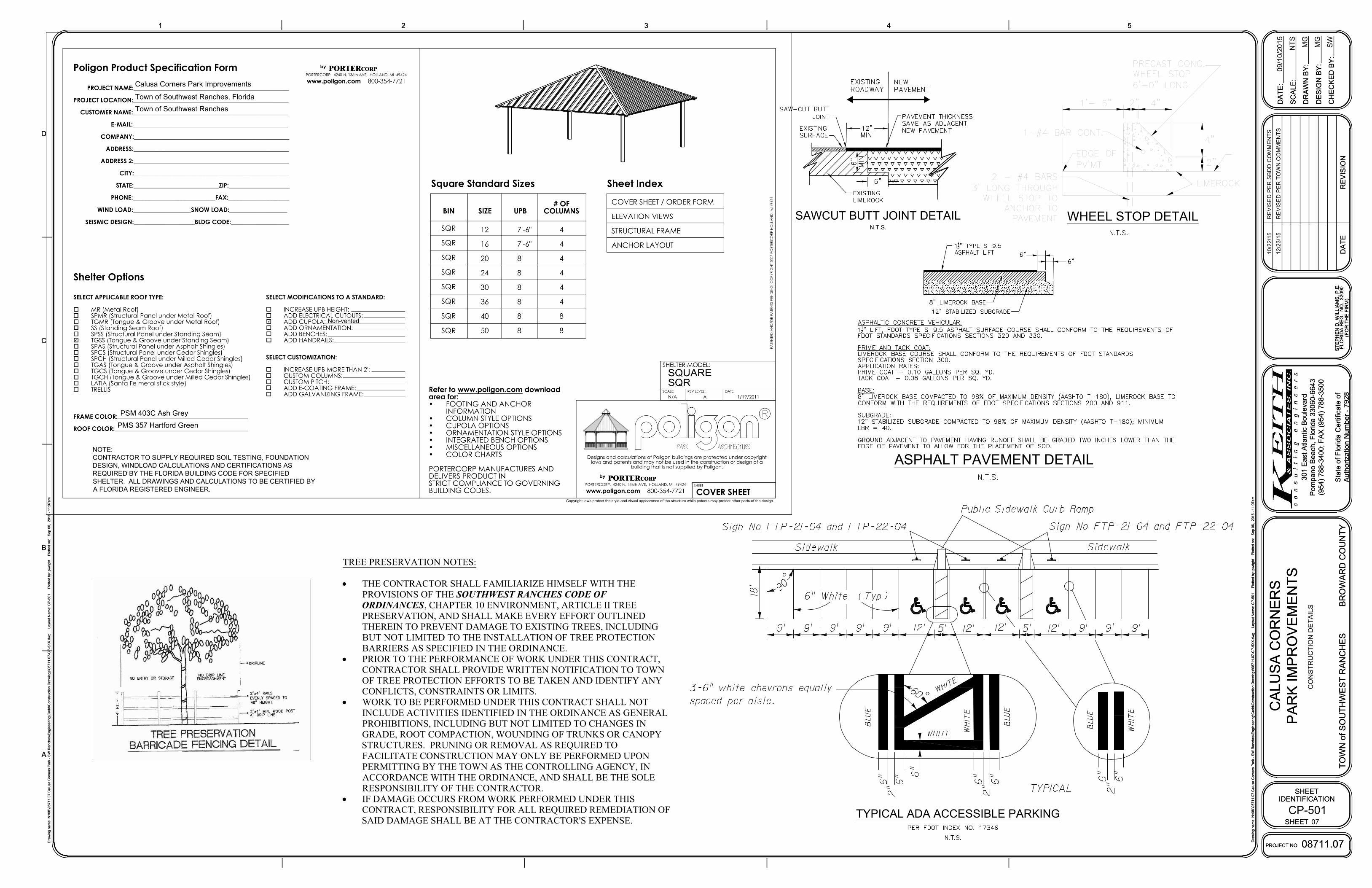
WHEEL STOP DETAILSAWCUT BUTT JOINT DETAIL
N.T.S.
ASPHALT PAVEMENT DETAIL
TYPICAL ADA ACCESSIBLE PARKING
NOTE:
CONTRACTOR TO SUPPLY REQUIRED SOIL TESTING, FOUNDATION
DESIGN, WINDLOAD CALCULATIONS AND CERTIFICATIONS AS
REQUIRED BY THE FLORIDA BUILDING CODE FOR SPECIFIED
SHELTER. ALL DRAWINGS AND CALCULATIONS TO BE CERTIFIED BY
A FLORIDA REGISTERED ENGINEER.
CP-501
09/10/2015
NT
S
MG
MG
SW
CO
NS
TR
UC
TIO
N D
ET
AILS
1
D
2 3
C
4 5
A
B
SHEET
IDENTIFICATION
DA
TE
PROJECT NO.
DA
TE
:
SC
ALE
:
DR
AW
N B
Y:
DE
SIG
N B
Y:
CH
EC
KE
D B
Y:
RE
VIS
IO
N
CA
LU
SA
C
OR
NE
RS
PA
RK
IM
PR
OV
EM
EN
TS
08711.07
TO
WN
of S
OU
TH
WE
ST
R
AN
CH
ES
B
RO
WA
RD
C
OU
NT
Y
301 E
ast A
tlantic B
oulevard
Pom
pano B
each, F
lorida 33060-6643
(954) 788-3400; F
AX
(954) 788-3500
State of F
lorida C
ertificate of
Authorization N
um
ber - 7928
Dra
win
g n
am
e: N
:\0
8'\0
87
11
.0
7 C
alu
sa
C
orn
ers P
ark - S
W R
an
ch
es\E
ng
in
ee
rin
g\C
ad
d\C
on
stru
ctio
n D
ra
win
gs\0
87
11
.0
7-C
P-5
XX
.d
wg
L
ayo
ut N
am
e: C
P-5
01
P
lo
tte
d b
y: p
wrig
ht P
lo
tte
d o
n: S
ep
0
6, 2
01
6 - 1
1:0
7a
m
Dra
win
g n
am
e: N
:\0
8'\0
87
11
.0
7 C
alu
sa
C
orn
ers P
ark - S
W R
an
ch
es\E
ng
in
ee
rin
g\C
ad
d\C
on
stru
ctio
n D
ra
win
gs\0
87
11
.0
7-C
P-5
XX
.d
wg
L
ayo
ut N
am
e: C
P-5
01
P
lo
tte
d b
y: p
wrig
ht P
lo
tte
d o
n: S
ep
0
6, 2
01
6 - 1
1:0
7a
m
SHEET
(F
OR
T
HE
F
IR
M)
ST
EP
HE
N D
. W
IL
LIA
MS
, P
.E
.
FL
OR
ID
A R
EG
. N
O. 3
20
90
07
1
D
2 3
C
4 5
A
B
SHEET
IDENTIFICATION
DA
TE
PROJECT NO.
DA
TE
:
SC
ALE
:
DR
AW
N B
Y:
DE
SIG
N B
Y:
CH
EC
KE
D B
Y:
RE
VIS
IO
N
CA
LU
SA
C
OR
NE
RS
PA
RK
IM
PR
OV
EM
EN
TS
08711.07
TO
WN
of S
OU
TH
WE
ST
R
AN
CH
ES
B
RO
WA
RD
C
OU
NT
Y
301 E
ast A
tlantic B
oulevard
Pom
pano B
each, F
lorida 33060-6643
(954) 788-3400; F
AX
(954) 788-3500
State of F
lorida C
ertificate of
Authorization N
um
ber - 7928
Dra
win
g n
am
e: N
:\0
8'\0
87
11
.0
7 C
alu
sa
C
orn
ers P
ark - S
W R
an
ch
es\E
ng
in
ee
rin
g\C
ad
d\C
on
stru
ctio
n D
ra
win
gs\0
87
11
.0
7-C
P-5
XX
.d
wg
L
ayo
ut N
am
e: C
P-5
01
P
lo
tte
d b
y: p
wrig
ht P
lo
tte
d o
n: S
ep
0
6, 2
01
6 - 1
1:0
7a
m
Dra
win
g n
am
e: N
:\0
8'\0
87
11
.0
7 C
alu
sa
C
orn
ers P
ark - S
W R
an
ch
es\E
ng
in
ee
rin
g\C
ad
d\C
on
stru
ctio
n D
ra
win
gs\0
87
11
.0
7-C
P-5
XX
.d
wg
L
ayo
ut N
am
e: C
P-5
01
P
lo
tte
d b
y: p
wrig
ht P
lo
tte
d o
n: S
ep
0
6, 2
01
6 - 1
1:0
7a
m
SHEET
(F
OR
T
HE
F
IR
M)
ST
EP
HE
N D
. W
IL
LIA
MS
, P
.E
.
FL
OR
ID
A R
EG
. N
O. 3
20
90
10
/2
2/1
5R
EV
IS
ED
P
ER
S
BD
D C
OM
ME
NT
S
TREE PRESERVATION NOTES:
· THE CONTRACTOR SHALL FAMILIARIZE HIMSELF WITH THEPROVISIONS OF THE SOUTHWEST RANCHES CODE OFORDINANCES, CHAPTER 10 ENVIRONMENT, ARTICLE II TREEPRESERVATION, AND SHALL MAKE EVERY EFFORT OUTLINEDTHEREIN TO PREVENT DAMAGE TO EXISTING TREES, INCLUDINGBUT NOT LIMITED TO THE INSTALLATION OF TREE PROTECTIONBARRIERS AS SPECIFIED IN THE ORDINANCE.
· PRIOR TO THE PERFORMANCE OF WORK UNDER THIS CONTRACT,CONTRACTOR SHALL PROVIDE WRITTEN NOTIFICATION TO TOWNOF TREE PROTECTION EFFORTS TO BE TAKEN AND IDENTIFY ANYCONFLICTS, CONSTRAINTS OR LIMITS.
· WORK TO BE PERFORMED UNDER THIS CONTRACT SHALL NOTINCLUDE ACTIVITIES IDENTIFIED IN THE ORDINANCE AS GENERALPROHIBITIONS, INCLUDING BUT NOT LIMITED TO CHANGES INGRADE, ROOT COMPACTION, WOUNDING OF TRUNKS OR CANOPYSTRUCTURES. PRUNING OR REMOVAL AS REQUIRED TOFACILITATE CONSTRUCTION MAY ONLY BE PERFORMED UPONPERMITTING BY THE TOWN AS THE CONTROLLING AGENCY, INACCORDANCE WITH THE ORDINANCE, AND SHALL BE THE SOLERESPONSIBILITY OF THE CONTRACTOR.
· IF DAMAGE OCCURS FROM WORK PERFORMED UNDER THISCONTRACT, RESPONSIBILITY FOR ALL REQUIRED REMEDIATION OFSAID DAMAGE SHALL BE AT THE CONTRACTOR'S EXPENSE.
12
/2
3/1
5R
EV
IS
ED
P
ER
T
OW
N C
OM
ME
NT
S
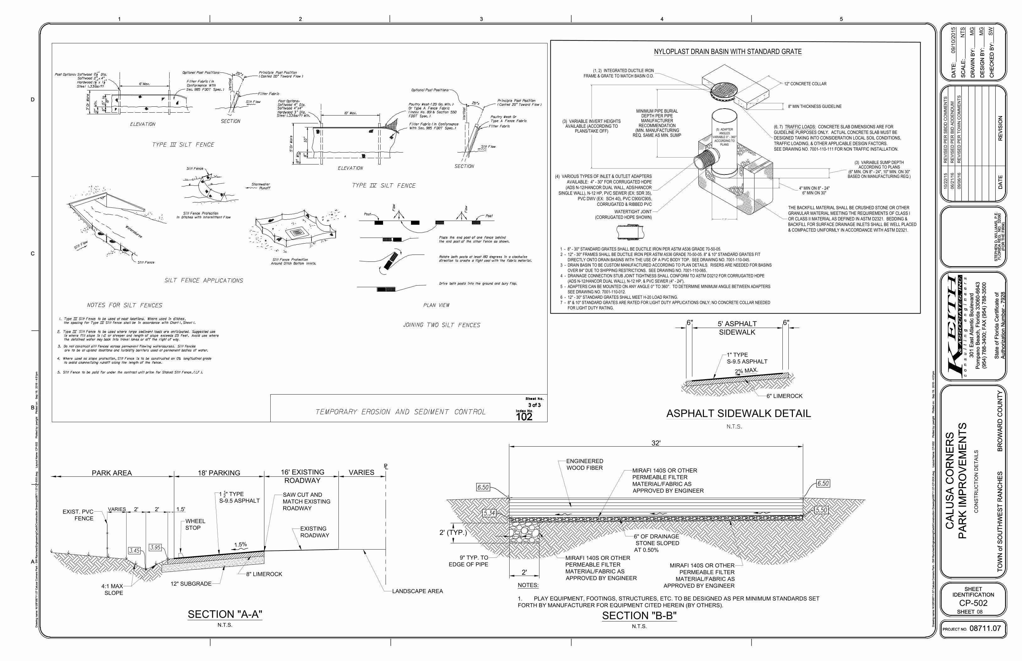
32'
MIRAFI 140S OR OTHER
PERMEABLE FILTER
MATERIAL/FABRIC AS
APPROVED BY ENGINEER
ENGINEERED
WOOD FIBER
MIRAFI 140S OR OTHER
PERMEABLE FILTER
MATERIAL/FABRIC AS
APPROVED BY ENGINEER
SECTION "B-B"
N.T.S.
NOTES:
1. PLAY EQUIPMENT, FOOTINGS, STRUCTURES, ETC. TO BE DESIGNED AS PER MINIMUM STANDARDS SET
FORTH BY MANUFACTURER FOR EQUIPMENT CITED HEREIN (BY OTHERS).
1
1
2
" TYPE
S-9.5 ASPHALT
EXISTING
ROADWAY
SAW CUT AND
MATCH EXISTING
ROADWAY
18' PARKING
1.5
%
12" SUBGRADE
8" LIMEROCK
16' EXISTING
ROADWAY
PARK AREA
SECTION "A-A"
N.T.S.
P
L
LANDSCAPE AREA
XX
EXIST. PVC
FENCE
WHEEL
STOP
VARIES
(5) ADAPTERANGLES
VARIABLE 0° - 360°ACCORDING TO
PLANS
8" - 30"
12" CONCRETE COLLAR
8" MIN THICKNESS GUIDELINE
(3) VARIABLE SUMP DEPTHACCORDING TO PLANS
(6" MIN. ON 8" - 24", 10" MIN. ON 30"BASED ON MANUFACTURING REQ.)
4" MIN ON 8" - 24"6" MIN ON 30"
MINIMUM PIPE BURIALDEPTH PER PIPEMANUFACTURER
RECOMMENDATION(MIN. MANUFACTURING
REQ. SAME AS MIN. SUMP)
(3) VARIABLE INVERT HEIGHTSAVAILABLE (ACCORDING TO
PLANS/TAKE OFF)
THE BACKFILL MATERIAL SHALL BE CRUSHED STONE OR OTHERGRANULAR MATERIAL MEETING THE REQUIREMENTS OF CLASS IOR CLASS II MATERIAL AS DEFINED IN ASTM D2321. BEDDING &BACKFILL FOR SURFACE DRAINAGE INLETS SHALL BE WELL PLACED& COMPACTED UNIFORMLY IN ACCORDANCE WITH ASTM D2321.
WATERTIGHT JOINT(CORRUGATED HDPE SHOWN)
NYLOPLAST DRAIN BASIN WITH STANDARD GRATE
1 - 8" - 30" STANDARD GRATES SHALL BE DUCTILE IRON PER ASTM A536 GRADE 70-50-05.2 - 12" - 30" FRAMES SHALL BE DUCTILE IRON PER ASTM A536 GRADE 70-50-05. 8" & 10" STANDARD GRATES FIT DIRECTLY ONTO DRAIN BASINS WITH THE USE OF A PVC BODY TOP. SEE DRAWING NO. 7001-110-045.3 - DRAIN BASIN TO BE CUSTOM MANUFACTURED ACCORDING TO PLAN DETAILS. RISERS ARE NEEDED FOR BASINS OVER 84" DUE TO SHIPPING RESTRICTIONS. SEE DRAWING NO. 7001-110-065.4 - DRAINAGE CONNECTION STUB JOINT TIGHTNESS SHALL CONFORM TO ASTM D3212 FOR CORRUGATED HDPE (ADS N-12/HANCOR DUAL WALL), N-12 HP, & PVC SEWER (4" - 24").5 - ADAPTERS CAN BE MOUNTED ON ANY ANGLE 0° TO 360°. TO DETERMINE MINIMUM ANGLE BETWEEN ADAPTERS SEE DRAWING NO. 7001-110-012.6 - 12" - 30" STANDARD GRATES SHALL MEET H-20 LOAD RATING.7 - 8" & 10" STANDARD GRATES ARE RATED FOR LIGHT DUTY APPLICATIONS ONLY; NO CONCRETE COLLAR NEEDED FOR LIGHT DUTY RATING.
(6, 7) TRAFFIC LOADS: CONCRETE SLAB DIMENSIONS ARE FORGUIDELINE PURPOSES ONLY. ACTUAL CONCRETE SLAB MUST BEDESIGNED TAKING INTO CONSIDERATION LOCAL SOIL CONDITIONS,TRAFFIC LOADING, & OTHER APPLICABLE DESIGN FACTORS.SEE DRAWING NO. 7001-110-111 FOR NON TRAFFIC INSTALLATION.
(1, 2) INTEGRATED DUCTILE IRONFRAME & GRATE TO MATCH BASIN O.D.
(4) VARIOUS TYPES OF INLET & OUTLET ADAPTERSAVAILABLE: 4" - 30" FOR CORRUGATED HDPE
(ADS N-12/HANCOR DUAL WALL, ADS/HANCORSINGLE WALL), N-12 HP, PVC SEWER (EX: SDR 35),
PVC DWV (EX: SCH 40), PVC C900/C905,CORRUGATED & RIBBED PVC
1" TYPE
S-9.5 ASPHALT
6" LIMEROCK
5' ASPHALT
SIDEWALK
ASPHALT SIDEWALK DETAIL
2%
MA
X.
6"6"
4:1 MAX
SLOPE
2' 2' 1.5'VARIES
6" OF DRAINAGE
STONE SLOPED
AT 0.50%
2'
2' (TYP.)
MIRAFI 140S OR OTHER
PERMEABLE FILTER
MATERIAL/FABRIC AS
APPROVED BY ENGINEER
9" TYP. TO
EDGE OF PIPE
CP-502
09/10/2015
NT
S
MG
MG
SW
CO
NS
TR
UC
TIO
N D
ET
AILS
1
D
2 3
C
4 5
A
B
SHEET
IDENTIFICATION
DA
TE
PROJECT NO.
DA
TE
:
SC
ALE
:
DR
AW
N B
Y:
DE
SIG
N B
Y:
CH
EC
KE
D B
Y:
RE
VIS
IO
N
CA
LU
SA
C
OR
NE
RS
PA
RK
IM
PR
OV
EM
EN
TS
08711.07
TO
WN
of S
OU
TH
WE
ST
R
AN
CH
ES
B
RO
WA
RD
C
OU
NT
Y
301 E
ast A
tlantic B
oulevard
Pom
pano B
each, F
lorida 33060-6643
(954) 788-3400; F
AX
(954) 788-3500
State of F
lorida C
ertificate of
Authorization N
um
ber - 7928
Dra
win
g n
am
e: N
:\0
8'\0
87
11
.0
7 C
alu
sa
C
orn
ers P
ark - S
W R
an
ch
es\E
ng
in
ee
rin
g\C
ad
d\C
on
stru
ctio
n D
ra
win
gs\0
87
11
.0
7-C
P-5
XX
.d
wg
L
ayo
ut N
am
e: C
P-5
02
P
lo
tte
d b
y: p
wrig
ht P
lo
tte
d o
n: S
ep
1
9, 2
01
6 - 4
:5
1p
m
Dra
win
g n
am
e: N
:\0
8'\0
87
11
.0
7 C
alu
sa
C
orn
ers P
ark - S
W R
an
ch
es\E
ng
in
ee
rin
g\C
ad
d\C
on
stru
ctio
n D
ra
win
gs\0
87
11
.0
7-C
P-5
XX
.d
wg
L
ayo
ut N
am
e: C
P-5
02
P
lo
tte
d b
y: p
wrig
ht P
lo
tte
d o
n: S
ep
1
9, 2
01
6 - 4
:5
1p
m
SHEET
(F
OR
T
HE
F
IR
M)
ST
EP
HE
N D
. W
IL
LIA
MS
, P
.E
.
FL
OR
ID
A R
EG
. N
O. 3
20
90
08
1
D
2 3
C
4 5
A
B
SHEET
IDENTIFICATION
DA
TE
PROJECT NO.
DA
TE
:
SC
ALE
:
DR
AW
N B
Y:
DE
SIG
N B
Y:
CH
EC
KE
D B
Y:
RE
VIS
IO
N
CA
LU
SA
C
OR
NE
RS
PA
RK
IM
PR
OV
EM
EN
TS
08711.07
TO
WN
of S
OU
TH
WE
ST
R
AN
CH
ES
B
RO
WA
RD
C
OU
NT
Y
301 E
ast A
tlantic B
oulevard
Pom
pano B
each, F
lorida 33060-6643
(954) 788-3400; F
AX
(954) 788-3500
State of F
lorida C
ertificate of
Authorization N
um
ber - 7928
Dra
win
g n
am
e: N
:\0
8'\0
87
11
.0
7 C
alu
sa
C
orn
ers P
ark - S
W R
an
ch
es\E
ng
in
ee
rin
g\C
ad
d\C
on
stru
ctio
n D
ra
win
gs\0
87
11
.0
7-C
P-5
XX
.d
wg
L
ayo
ut N
am
e: C
P-5
02
P
lo
tte
d b
y: p
wrig
ht P
lo
tte
d o
n: S
ep
1
9, 2
01
6 - 4
:5
1p
m
Dra
win
g n
am
e: N
:\0
8'\0
87
11
.0
7 C
alu
sa
C
orn
ers P
ark - S
W R
an
ch
es\E
ng
in
ee
rin
g\C
ad
d\C
on
stru
ctio
n D
ra
win
gs\0
87
11
.0
7-C
P-5
XX
.d
wg
L
ayo
ut N
am
e: C
P-5
02
P
lo
tte
d b
y: p
wrig
ht P
lo
tte
d o
n: S
ep
1
9, 2
01
6 - 4
:5
1p
m
SHEET
(F
OR
T
HE
F
IR
M)
ST
EP
HE
N D
. W
IL
LIA
MS
, P
.E
.
FL
OR
ID
A R
EG
. N
O. 3
20
90
10
/2
2/1
5R
EV
IS
ED
P
ER
S
BD
D C
OM
ME
NT
S
06
/2
1/1
6R
EV
IS
ED
P
ER
B
ID
A
DD
EN
DU
M
09
/0
6/1
6R
EV
IS
ED
P
ER
T
OW
N C
OM
ME
NT
S

CP-503
08711.07
10/22/15 REVISED PER SBDD COMMENTS1