fin al operation and maintenanc e manual - fmc …projects.fmcti.cl/mmh/manual de operacion/manual...
TRANSCRIPT

FIN
FMC Techn
NAL OPERAT
nologies Chile L
TION AND MA
ORDEN D
FMC
Ltda. Callao #2
AINTENANC
E COMPRA
C TECHNOL
970 Oficina 70
E MANUAL –
H336073-PM
OGIES PROJ
04 Edificio Stud
– MINA MINIS
M031/A 45011
JECT B6042
dio Las Condes
STRO HALES
90525
Fono: 56‐2‐22
S PROJECT
2320825

11/10 1
X1 X 2 X 3
Y4
Y5
Y1
Y2Y3
Y
et
O
Technical ManualTechnical Manual
Design, Installation,Operation andMaintenance
Design, Installation,Operation andMaintenance

11/102

11/10 1
Table of ConTenTs DESIGN ...........................................................................3 Introduction ................................................................4 Beltwall Products .......................................................5 Corrugated Sidewalls .........................................5 Beltwall Cleats ...................................................6 Beltwall Cross-Rigid Belting ...............................9 Initial Considerations ..............................................12 The Choice for Beltwall ....................................12 Material Characteristic Considerations ............12 ConveyorConfigurations .................................13 Design Considerations ............................................16 Belt Speed .......................................................16 BeltProfiles ......................................................18 Belt Horsepower ..............................................21 Belt Tension Ratings ........................................21 Belt End Preparation ........................................22 Conveyor Components and Design .......................24 Pulleys and Bend Sections ..............................24 DeflectionWheels ............................................28 Idlers ................................................................29 Slider Beds.......................................................35 Guide/Training Idlers ........................................35 Take-Up Arrangements ....................................36 Inspection/Access Panels ................................36 Belt Cleaning....................................................37 Cleat Spillage Plates ........................................43 Assistance and Drawing Review ............................44 CorrugatedSidewallSampleSpecifications .........45 Design Information Data Sheet ..............................47 INSTALLATION ...................................................................49 Belt Storage ..............................................................50 Belt Installation ........................................................51 Belt Splicing .............................................................56 Beltwall Packaging Options ....................................61 OPERATIONS & MAINTENANCE ......................................63 Troubleshooting .......................................................69 Preventive Maintenance Checklist .........................73 GLOSSARY ........................................................................75
This publication is intended to provide general guidelines pertaining to the design, installation, operation, and maintenance of Beltwall belting manufactured by Beltwall Division, Beltservice Corporation. All information is given in good faith and is offered as a guide only. The user of this information must determine the suitability of this information for his/her own purposes. Beltservice Corporation and its Beltwall Division shall have no liability whatsoever for any error or omission in the contents of this publication, or for any loss or damage which may result from reliance by any person on such contents. All products are subject to Beltwall’s term of sale.

11/102

11/10 3
Design
11/104
INTRODUCTION
Beltwall® belting offers the most advanced conveying concept available in the industry today.
The ability to change planes of travel in an extremely short distance and elevate at any angle up
to and including 90 degrees allows the conveyor designer a nearly unlimited range of engineering
options.
The design and selection of Beltwall belting and conveyors present unique requirements
thatmustbecarefullyfollowedinordertorealizethefullpotentialoftheBeltwallconcept.While
most standard and conventional conveyor design techniques are applicable, there are additional
considerations which are necessary to ensure the successful operation of any Beltwall system.
However, while unique, these considerations are quite simple in both their design and
application. The basic selection and design techniques outlined in this manual, when followed
closely, will provide the foundation for a solid application of Beltwall technology and will allow
successful and continuing service from Beltwall belting with minimal maintenance.
The standards depicted here are based upon the results of years of design, testing, evaluation,
and the experience gained from thousands of successful installations in virtually every industry
throughout the world. These techniques are, however, intended exclusively for use with Beltwall
belting. The design and manufacturing standards inherent only in Beltwall belts may not be
appropriate for the products of other manufacturers, and therefore should only be used for
belting designed and manufactured by Beltwall Division, Beltservice Corporation.

11/10 5
BELTWALL PRODUCTS
BELTWALL CORRUGATED SIDEWALLS
Beltwall offers a full line of corrugated sidewalls in a complete line-up of small sizes and
compounds. Heights range from 1 inch (25mm) to 16 inches (400mm) including all standard
metric sizes with compounds in Black Standard, Black Oil Resistant, Black High Heat Resistant,
BlackFlameRetardant(FR),BlackHighOilResistant,andWhiteOilandFatResistant(FDA),
to handle a full range of capacities and material characteristics
BELTWALL CORRUGATED SIDEWALLS
Eachcompoundisspeciallyformulatedforextremelyhighflexlifeandabrasionresistance.
Microscopicstrengtheningfibersarecompoundedintotherubberforhighcutandtearresistance
under even the most severe operating conditions. All Beltwall sidewalls 6” and taller also have a
fabric ply embedded in the vertical sections for unsurpassed strength and durability.
Pulley Diameter In Inches
Height In
Inches
WallWidth (in.)
Pitch(in.)
Black Std/ High Heat
Oil Resistant/ FR/ White
4 1 8
4 2/1-1 8
2
1-1/2 1
6 88 2/1-2 12
01 3 12
01 4 145
2 1-1/2
12 16
61 6 20
02 8 2410
3-1/8 2-1/2
24 30
63 21 48
164-1/8 3-1/2
42 54
Pulley Diameter In millimeters
HeightIn
mm
WallWidth (mm.)
Pitch(mm)
Black Std/ High Heat
Oil Resistant/ FR/ White
201 52 152
201 83 152
51
38 25
152 203 302 46 305
452 67 305
452 201 355127
51 38
305 406
604 251 508
805 302 610254
79 64
610 762
419 503 1,219
406105 89
1,066 1,371
Height 1"25 mm
1 1/2"38 mm
2"51 mm
2 1/2"64 mm
3"76 mm
4"102 mm
5"127 mm
6"152 mm
8"203 mm
10"254 mm
12"305 mm
16"406 mm

11/106
BELTWALL CLEATS
A complete array of cleat styles and sizes complements the Beltwall sidewalls for conveying
any capacity at any angle. The cleats are also available in Black Standard, Black Oil Resistant,
BlackHighHeatResistant,BlackFlameRetardant(FR),BlackHighOilResistant,andWhiteOil
and Fat Resistant (FDA) compounds.
All Beltwall cleats are hot-molded to the belt covers by a unique, patented process that
greatly reduces the possibility of cleat separation during operation.
Straight “I” cleats are available in heights from 1/2” (13mm) through 15-1/4” (387mm). “I”
cleats are generally used on inclines up to 40 degrees. Standard heights through 5” (127mm) are
a one-piece rubber hot-molded construction. Those 5-1/2” (140mm) and taller are an unequalled
two-piece design with a “U” shaped hot-molded rubber foot into which a replaceable urethane
cleat blade is bolted. Under even the most abrasive conditions, the urethane blade construction
proves far superior to other materials. In the unlikely event of cleat damage, however, the blades
arereadilyrenewablebyremovingthebaseboltsandrefittingreplacementblades.
Beltwall “I” Cleats
Height 1"25 mm
1/2"13 mm
1-1/2"38 mm
2"51 mm
2-1/2"64 mm
3-1/2"89 mm
4-1/2"114 mm
5-1/2"140 mm
7-1/2"191 mm
9-1/2"241 mm11-1/4"286 mm
15-1/4"387 mm
I or I(B)I I or I(B) IB
( ) Indicates optional two-bolt attachment of cleats to sidewalls. B Denotes two-bolt attachment of cleats to sidewalls.

11/10 7
“I” cleats can be fastened to the sidewalls by means of bolt and bolt support arrangements for
additional belt stability where effective widths are 24” (610mm) or more with rubber cleats.
Sidewall Attachment to “I” Cleats
Scoop “C” cleats are available in heights from 1/2” (13mm) through 5” (127mm). “C” cleats
are used when additional capacity is required in steep angle applications up to and including 90
degrees. All “C” cleats are a one-piece rubber hot-molded construction.
It is not practical to attach “C” cleats to the sidewalls. Attachments to the sidewalls require the
alignment of a straight cleat section perpendicular to the belt surface and aligned with the inner
vertical section of the sidewall to prevent the radial misalignment of the cleat and sidewall as the
belt negotiates bends and pulleys.
Beltwall “C” Cleats
Height 1"25 mm
1-1/2"38 mm
2"51 mm
2-1/2"64 mm
3-1/2"89 mm
4-1/2"114 mm
C5"
127 mm

11/108
Combination “S” cleats are available in heights from 4 1/2” (114mm) through 15-1/4” (387mm).
“S”cleatsarespecifiedforhighercapacityapplicationsatanglesusuallygreaterthan40degrees.
A one-piece rubber hot-molded construction is available for heights through 5-1/2” (140mm),
and the two-piece design with a “U” shaped rubber hot-molded foot into which an angled cleat
blade is bolted is utilized for heights 5-1/2” (140mm) and taller. Either the one-piece or two-piece
construction is available for 5-1/2” (140mm) cleats.
Whiletheangledsectionofthe“S”shapeprovidesadditional“percleat”volumecapacity,
the vertical base section allows attachment to the sidewall by means of bolt and bolt support
arrangement for additional belt stability on designs with 24” (610mm) and more effective widths
between the walls with rubber cleats and on all inclined applications 75 degrees or steeper.
Forfine, free-flowingmaterials,specialsidecleatpartitionsareavailable incombinationwith
theattachmentof thesidewall toeliminateanyfluidizingormaterial leakageonsteep-angle
applications.
Beltwall “S” Cleats
Height 4-1/2"114 mm
5-1/2"140 mm
7- 1/2"191 mm
9-1/2"241 mm
11-1/4"286 mm
15-1/4"387 mm
SB
SS S or S(B)
( ) I ndicates optional two-bolt attachment of cleats to sidewalls. B D enotes two-bolt attachment of cleats to sidewalls.
Sidewall Attachment to “S” Cleats
( ) Indicates optional two-bolt attachment of cleats to sidewalls.B Denotes two-bolt attachment of cleats to sidewalls.
11/10 9
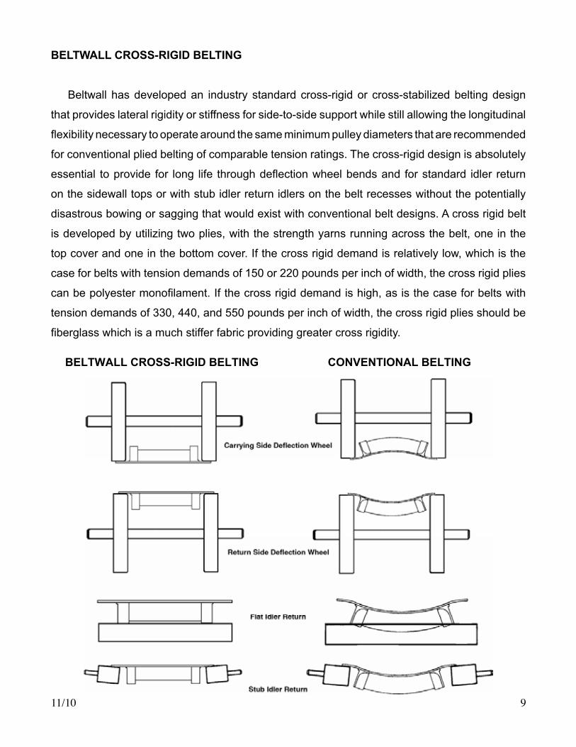
BELTWALL CROSS-RIGID BELTING
Beltwall has developed an industry standard cross-rigid or cross-stabilized belting design
that provides lateral rigidity or stiffness for side-to-side support while still allowing the longitudinal
flexibilitynecessarytooperatearoundthesameminimumpulleydiametersthatarerecommended
for conventional plied belting of comparable tension ratings. The cross-rigid design is absolutely
essential toprovide for long life throughdeflectionwheelbendsand forstandard idler return
on the sidewall tops or with stub idler return idlers on the belt recesses without the potentially
disastrous bowing or sagging that would exist with conventional belt designs. A cross rigid belt
is developed by utilizing two plies, with the strength yarns running across the belt, one in the
top cover and one in the bottom cover. If the cross rigid demand is relatively low, which is the
case for belts with tension demands of 150 or 220 pounds per inch of width, the cross rigid plies
canbepolyestermonofilament.Ifthecrossrigiddemandishigh,asisthecaseforbeltswith
tension demands of 330, 440, and 550 pounds per inch of width, the cross rigid plies should be
fiberglasswhichisamuchstifferfabricprovidinggreatercrossrigidity.
BELTWALL CROSS-RIGID BELTING CONVENTIONAL BELTING

11/1010
Beltwall cross-rigid belting is available in a full range of tension ratings in Black Standard,
Black Oil Resistant, Black High Oil Resistant, Black High Heat Resistant, Black Flame Retardant
(FR),andWhiteOilandFatResistant(FDA)compounds.Listedbelowisabriefdescriptionof
each compound:
1. Black standard is the most common rubber belt compound used in over 75% of all belting
applications. It provides excellent abrasion resistance and good cut and gouge resistance.
2. Black oil resistant is compounded to resist the effect of wood chips, moderately oily grain,
and waste water treatment applications.
3. Black high oil resistant is compounded for maximum resistance to mineral, animal, and
vegetableoils,oilysteelparts,crushedsoybeans,andtrashrecycling.Itisalsofireretardant.
4. Black high heat resistant is compounded to withstand temperatures between 180°F
(80°C) and 350°F (175°C). The base belt is compounded from EPDM rubber. Cleats up to 5-1/2”
(140mm) are also EPDM. Cleats over 5-1/2” (140mm) are high heat urethane bolted into an
EPDM cleat base. Sidewalls are butyl. Due to the concentration of material at the cleat base,
creating greater pressure on the belt than on conventional conveyor belts, it is necessary to use
high heat resistant belts at lower temperature 180°F (80°C) than for conventional belts. EPDM
and butyl compounds are also quite often used for chemical resistance. Please contact Beltwall
forspecificationassistance.
5.BlackflameRetardantFR-SBRiscompoundedtoselfextinguishwithin60secondsafter
aflameisremovedfromthebelt.
6. Stacker is Goodyear’s compound for superior abrasion resistance.
7. RMA-1 is recommended for severe cut and gouge resistance.
Each Beltwall cross rigid belt contains high modules longitudinal tension plies for a belt
carcass construction that withstands the most rigorous design applications.
Standard cover thicknesses are listed below. Because conveyed material is held static on the
Beltwall belt, cover thickness is typically less than that found on a conventional belt conveying
the same material. On a conventional belt, there is constant abrasion due to material movement
each time the belt climbs over an idler. Heavier covers, Stacker and RMA-1, are available if the
belt will be exposed to extremely abrasive materials such as copper or nickel ore or if the belt
willbeexposedtoheavyimpact.ConsultBeltwallforspecifics.

11/10 11
Note:
1.800PIWCrossrigidbeltsareavailableforhightensionL-shapedsystems.
2. Steel cable cross rigid belts with steel cross rigid plies are available for high tension
S-shaped systems.
3. Consult Beltwall for belt selection.
For horizontal systems without cleats, cross rigid belting is not necessary with center distances
less than 50 feet (15.25m) and sidewall heights below 4” (102mm). If the center distance between
pulleys is greater than 50 feet (15.25m) or the sidewalls are 4” (102mm) in height or more cross
rigid belting is necessary to prevent the sidewalls from dishing in on the return and abrading
against the return structure.
BELTWALL CROSS-RIGID BELTS SEILP LLAWTLEB
Belts Covers
Tensile
X-Rigid
Nominal Thickness
WorkingTensionPIW
051 mm 7.8 ”23/11 2 2 eraB x ”61/1 etihW 2251 XWBBWX1522BlkStandard5/64”x1/16” 2 2 7/16” 11.1 mm 150 BWX1522BlkOilResistant5/64”x1/16” 2 2 7/16” 11.1 mm 150 BWX2222BlkStandard1/8”x1/16” 2 2 15/32” 11.8 mm 220 BWX2222BlkOilResistant1/8”x1/16” 2 2 15/32” 11.8 mm 220 BWX2222BlkFlameRetardant(FR)1/8”x1/16”2 2 15/32” 11.8 mm 220 BWX2222BlkHighOilResistant1/8”x1/16” 2 2 15/32” 11.8 mm 220 BWX2222BlkHeatResistant3/16”x1/16” 2 2 9/16” 14.2 mm 220 BWX3332BlkStandard1/8”x1/16” 3 2 9/16” 14.2 mm 330 BWX3332BlkOilResistant1/8”x1/16” 3 2 9/16” 14.2 mm 330 BWX3332BlkFlameRetardant(FR)1/8”x1/16”3 2 9/16” 14.2 mm 330 BWX3332BlkHighOilResistant1/8”x1/16” 3 2 9/16” 14.2 mm 330 BWX3332BlkHeatResistant3/16”x1/16” 3 2 5/8” 15.9 mm 330 BWX4442BlkStandard1/8”x1/16” 4 2 5/8” 15.9 mm 440 BWX4442BlkOilResistant1/8”x1/16” 4 2 5/8” 15.9 mm 440 BWX4442BlkFlameRetardant(FR)1/8”x1/16”4 2 5/8” 15.9 mm 440 BWX4442BlkHighOilResistant1/8”x1/16” 4 2 5/8” 15.9 mm 440 BWX4442BlkHeatResistant3/16”x1/16” 4 2 23/32” 18.2 mm 440 BWX5552BlkStandard1/8”x1/16” 5 2 3/4” 19.0 mm 550 BWX5552OilResistant1/8”x1/16” 5 2 3/4” 19.0 mm 550 BWX5552FlameRetardant(FR)1/8”x1/16”5 2 3/4” 19.0 mm 550 BWX5552HighOilResistant1/8”x1/16” 5 2 3/4” 19.0 mm 550 BWX5552HeatResistant3/16”x1/16” 5 2 13/16" 20.6 mm 550
Cross Rigid Plies Tension Plies
Belt End View

11/1012
INITIAL CONSIDERATIONS
THE CHOICE FOR BELTWALL
Beltwall belting can be used in almost any application for transporting bulk materials. In every
instance, the Beltwall design virtually eliminates side spillage and can carry the capacities of
conventional troughed belts within a much narrower width.
However, the most valuable and cost-effective use of Beltwall is as an elevating device.
Whenevermaterialshavetobeliftedorelevated,Beltwallshouldbealogicalfirstconsideration.
Theoverallsavingsinstructure,conveyorcomponents,andfloororgroundspacecanusually
provide a very cost-effective alternative to conventional elevating means. Replacing up to three
separate systems (infeed, elevator, outfeed) with one eliminates transfer points, reduces material
degradation, increases versatility, and provides discharge capabilities at the very point of desired
delivery. Beltwall also provides long-term cost savings from a maintenance and replacement
standpoint as well.
MATERIAL CHARACTERISTIC CONSIDERATIONS
Beltwall belting is used in virtually every industry to convey almost any bulk material from
fine,dry,fluidicpowderstolarge-lumpminedminerals-fromfoodproductstowetcoal.When
considering Beltwall, of course all possible states of the material - wet or dry - must be taken into
account.
Saved Ground Space, Hardware,
and Structure
BELTWALL CONVEYOR SYSTEM VERSUS CONVENTIONAL BELT CONVEYOR

11/10 13
Loadinganddischargeoftheproductmustbeevaluatedwithregardtoeaseofmaterialflow,
maximum lump size, angle of repose and surcharge angle, oil or chemical content, moisture,
and temperature. It is critical in the consideration of Beltwall belting that the material can both be
loaded within the pockets and discharged acceptably.
CONVEYOR CONFIGURATIONS
The primary advantage of Beltwall belting is the design flexibility offered by its ability to
change planes quickly through a very small vertical curve and negotiate up to an including 90
degreeinclines.ThemostcommonBeltwallconveyorconfigurationsare:1.horizontal,2.straight
incline,3.reverseL-shaped,4.L-shaped,5.S-shaped,6.90degreeS-shaped,7.S-shaped
with angled infeed and/or discharge, 8. S-shaped with additional bends.
In addition to the elevating capabilities, the designer should also consider the ability of Beltwall
belts to reverse, as indicated by the directional arrows in both directions, and in some cases
become an excellent declining, even power-generative conveyor.
1. 2. 3. 4.
5. 6. 7. 8.
11/1014
The following design guidelines should be considered when determining the conveyor
configuration:
LOADING
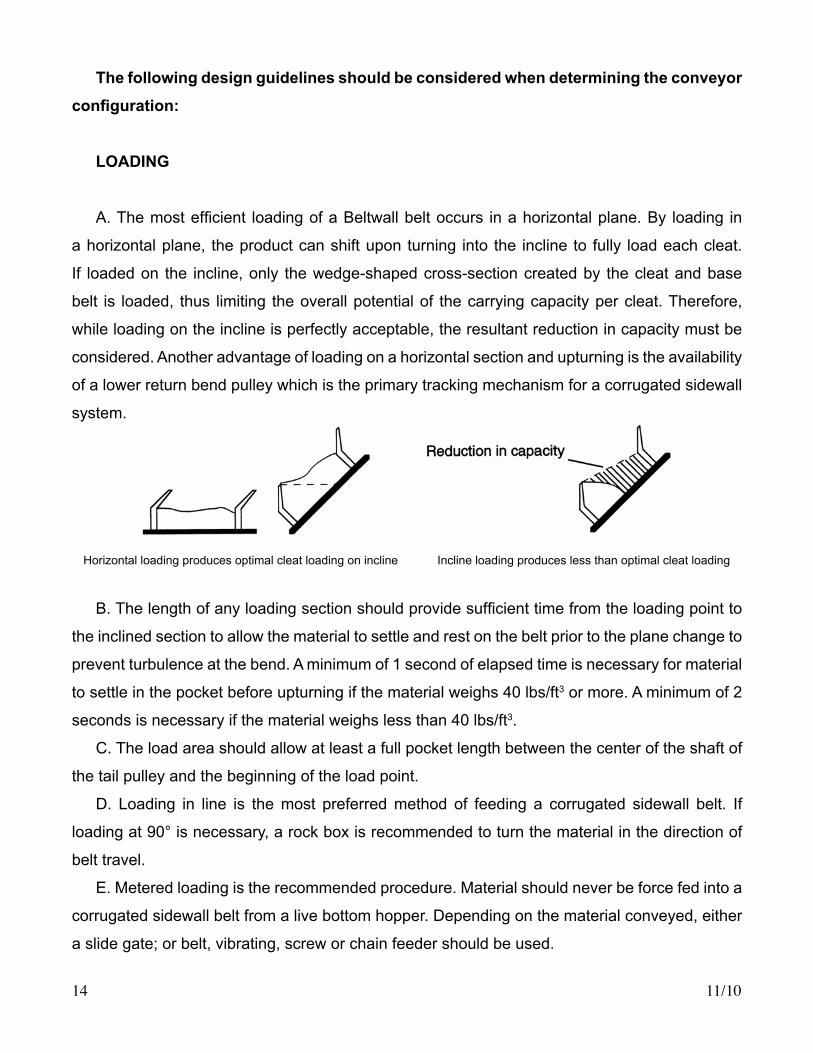
A.Themostefficient loadingofaBeltwallbeltoccurs inahorizontalplane.By loading in
a horizontal plane, the product can shift upon turning into the incline to fully load each cleat.
If loaded on the incline, only the wedge-shaped cross-section created by the cleat and base
belt is loaded, thus limiting the overall potential of the carrying capacity per cleat. Therefore,
while loading on the incline is perfectly acceptable, the resultant reduction in capacity must be
considered. Another advantage of loading on a horizontal section and upturning is the availability
of a lower return bend pulley which is the primary tracking mechanism for a corrugated sidewall
system.
B.Thelengthofanyloadingsectionshouldprovidesufficienttimefromtheloadingpointto
the inclined section to allow the material to settle and rest on the belt prior to the plane change to
prevent turbulence at the bend. A minimum of 1 second of elapsed time is necessary for material
to settle in the pocket before upturning if the material weighs 40 lbs/ft3 or more. A minimum of 2
seconds is necessary if the material weighs less than 40 lbs/ft3.
C. The load area should allow at least a full pocket length between the center of the shaft of
the tail pulley and the beginning of the load point.
D. Loading in line is themost preferredmethod of feeding a corrugated sidewall belt. If
loading at 90° is necessary, a rock box is recommended to turn the material in the direction of
belt travel.
E. Metered loading is the recommended procedure. Material should never be force fed into a
corrugated sidewall belt from a live bottom hopper. Depending on the material conveyed, either
a slide gate; or belt, vibrating, screw or chain feeder should be used.
Horizontal loading produces optimal cleat loading on incline Incline loading produces less than optimal cleat loading
11/10 15
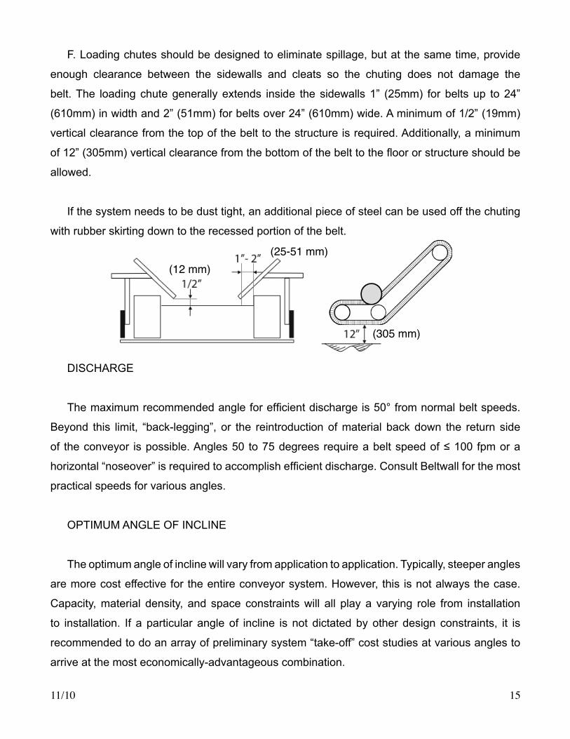
F.Loadingchutesshouldbedesignedtoeliminatespillage,butatthesametime,provide
enough clearance between the sidewalls and cleats so the chuting does not damage the
belt. The loading chute generally extends inside the sidewalls 1” (25mm) for belts up to 24”
(610mm) in width and 2” (51mm) for belts over 24” (610mm) wide. A minimum of 1/2” (19mm)
vertical clearance from the top of the belt to the structure is required. Additionally, a minimum
of12”(305mm)verticalclearancefromthebottomofthebelttothefloororstructureshouldbe
allowed.
If the system needs to be dust tight, an additional piece of steel can be used off the chuting
with rubber skirting down to the recessed portion of the belt.
DISCHARGE
Themaximumrecommendedangleforefficientdischargeis50°fromnormalbeltspeeds.
Beyond this limit, “back-legging”, or the reintroduction of material back down the return side
of theconveyor ispossible.Angles50 to75degreesrequireabeltspeedof≤100fpmora
horizontal“noseover”isrequiredtoaccomplishefficientdischarge.ConsultBeltwallforthemost
practical speeds for various angles.
OPTIMUMANGLEOFINCLINE
The optimum angle of incline will vary from application to application. Typically, steeper angles
are more cost effective for the entire conveyor system. However, this is not always the case.
Capacity, material density, and space constraints will all play a varying role from installation
to installation. If a particular angle of incline is not dictated by other design constraints, it is
recommended to do an array of preliminary system “take-off” cost studies at various angles to
arrive at the most economically-advantageous combination.

11/1016
DESIGN CONSIDERATIONS
BELT SPEED
Generally, the speed of a corrugated sidewall conveyor belt will be the same as the speed
of a conventional conveyor. However, Beltwall should always be consulted at speeds over 500
FPM (2.5m/sec). In addition, a dust collection expert should be consulted for conveying any
aerated or powdery material at speeds over 300 FPM (1.5m/sec.) to ensure the dust collection
system is capable of accepting any extra dusting caused by the cleats during loading. There are
several criteria beyond normal standards for belt speed determination that must be considered:
1.LOADING-Themostobviouscriteriaforbeltspeedconsiderationistheabilitytoloadthe
belt.OnBeltwallbeltsusingcleats,therequiredvolumeofmaterialmustbecapableoffilling
one cleat space or pocket before the next cleat passes the loading zone, thus eliminating the
“window” through which the material must pass.
The direction of loading - whether in line or angled to the center line of the Beltwall conveyor
- and the horizontal velocity of the material relative to the speed of the Beltwall belt - whether
falling straight down or trajected in line with the direction of travel of the Beltwall belt, have a
major effect on the ability to load the belt. As with all conveyors, the preferred method of loading
a Beltwall belt is in a direction in line with, and at a horizontal velocity equal to or slightly grater
than, the receiving belt.
One must also remember that material in general and lumps in particular are accelerated
instantaneously on a cleated Beltwall belt, and any resultant turbulence must be considered
Taking into account the length and width of the infeed area or opening, a gravimetric calculation
basedonthetotalverticaldropshouldbeperformedpriortofinalspeedselection.
2. TRAJECTORY - The two major areas of awareness that much be considered from a
trajectory standpoint are the discharge point and the noseover section.

11/10 17
The discharge point obviously is ultimately affected by the material trajectory in the design of
discharge chutes and clearances. The actual trajectory must take into consideration: 1. maximum
possible material depth (equal to the sidewall height), 2. belt speed, and 3. angle of discharge.
The discharge trajectory calculation is extremely important with Beltwall belting to prevent
the inadvertentplacementofbafflesorchutework thatwouldcausematerialor lumps tobe
deflectedbackagainstthebelt.Inthecaseofcleatedbelts,thereintroductionofmaterialinto
the cleated area can result in the “batting” of material out of the desired discharge area resulting
in both material carry-back and spillage as well as possible belt damage.
NOTE: Further discussion on discharge trajectories and calculations can be found in CEMA’s
Belt Conveyors for Bulk Materials.

11/1018
BELT PROFILES
Thethreemostcommonbeltprofileconstructionsare1.sidewallsmountedflushontheside
of thebasebeltwithoutcleatsforuse inhorizontalorslightly inclinedstraightconfigurations,
2.sidewallsmountedflushonthesideofthebeltwithcleatsbetweenthewallsforadditional
capacityonsteeperstraightinclines,and3.themostcommonprofile,sidewallsrecessedfrom
thebeltedge toallow forverticalbendsbymeansofdeflectioncomponentsandwithcleats
mounted between the walls for additional capacity.
In some cases, types 1 and 2 may be used with the sidewalls recessed to allow the use of
stub return idlers on wider belts or on heavier belts to prevent premature sidewall wear.
SIDEWALLRECESS
The sidewall recess should always be an absolute minimum of 10 percent of the sum of the
belt width plus the sidewall height.
In most cases, a larger than minimum recess is provided to allow for additional design comfort
andtoabsorbthetensionatthedownturndeflectionwheeloveragreaterarea;therebyallowing
the use of a lower tension belt.
Recess(R)≥.1 [ BeltWidth(BW)+SidewallHeight(H) ]
11/10 19
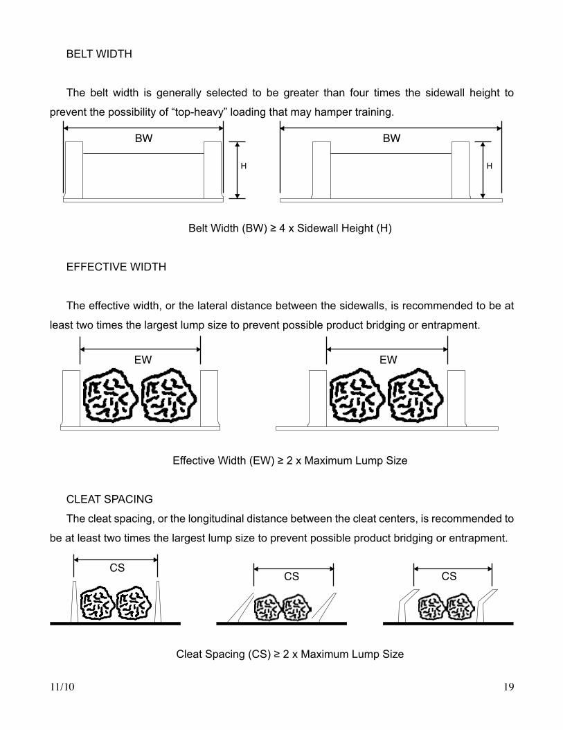
BELTWIDTH
The belt width is generally selected to be greater than four times the sidewall height to
prevent the possibility of “top-heavy” loading that may hamper training.
BeltWidth(BW)≥4xSidewallHeight(H)
EFFECTIVEWIDTH
The effective width, or the lateral distance between the sidewalls, is recommended to be at
least two times the largest lump size to prevent possible product bridging or entrapment.
EffectiveWidth(EW)≥2xMaximumLumpSize
CLEATSPACING
The cleat spacing, or the longitudinal distance between the cleat centers, is recommended to
be at least two times the largest lump size to prevent possible product bridging or entrapment.
CleatSpacing(CS)≥2xMaximumLumpSize
BW BW
H H
EW EW
CSCS CS
11/1020
Cleat spacing is always recommended to coincide with the pitch of the sidewall convolutions
in order to align the cleat with the vertical sidewall section and prevent material from spilling
around the cleat end through the convolution spaces.
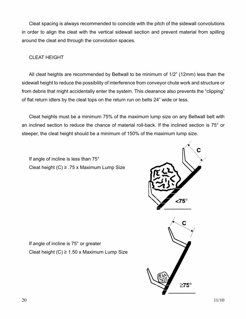
CLEATHEIGHT
All cleat heights are recommended by Beltwall to be minimum of 1/2” (12mm) less than the
sidewall height to reduce the possibility of interference from conveyor chute work and structure or
from debris that might accidentally enter the system. This clearance also prevents the “clipping”
offlatreturnidlersbythecleattopsonthereturnrunonbelts24”wideorless.
Cleat heights must be a minimum 75% of the maximum lump size on any Beltwall belt with
an inclined section to reduce the chance of material roll-back. If the inclined section is 75° or
steeper, the cleat height should be a minimum of 150% of the maximum lump size.
If angle of incline is less than 75°
Cleatheight(C)≥.75xMaximumLumpSize
If angle of incline is 75° or greater
Cleatheight(C)≥1.50xMaximumLumpSize

11/10 21
BELT HORSEPOWER
Belt horsepower calculations are based on standard CEMA formulas with slight differences
due to a lower friction factor since two bearings support the carrying idlers on a Beltwall belt
versus six bearings on the can idlers of a trough conveyor. Beltwall calculates only the running
horsepower, or the horsepower that must be delivered to the drive shaft during operation at the
full selected belt speed.
For motor horsepower selection, factors which also should be considered include start-up
acceleration time, possible start-up under full load, moisture, drive component losses, electric
motor logic circuitry, coupling design, possible power loss over lengthy electric motor cables,
operation temperature (Beltwall calculations assume temperature [Kt] factor of 1.0), loading the
belt to 100%, and any other external condition that might affect the operating conditions of the
system.
BELT TENSION RATINGS
TherearetwoareasofconsiderationforfinalBeltwallbasebelttensionratingselections:
1. The actual operating tensions at each point on the conveyor.
2. The cross-rigid limitations of each tension rating construction versus the selected belt width.
Under area 1 the actual operating tensions at each point along both the carrying and return
sides are checked to ensure the selected belt rating construction is adequate for all points under
all conditions. One of the most dramatic differences in tension rating selection occurs at the
concavebendsorupturnanddownturndeflectionpoints.Unlikeconventionalbelts,thedesigner
must remember that while total tensions in these areas are usually less than at the drive pulley,
thetensionstheremustbetotallysupportedbythedeflectionwheels,andthereforeonly the
recessed areas of the belt can be considered as the width of belt that must withstand the total
belt tension at that point. In other words, while the belt tensions at those points are generally
lower than at the drive or head pulley, the belt width used for the “tension per unit of width”
calculation is only a fraction of the total belt width. As a result, in the majority of cases, it is
thereforethedeflectionareas,ratherthanthedrivesections,thatbecomethedeterminingfactor
in the tension rating selection of the base belt.
11/1022
FINAL BELT SELECTION
There are a number of criteria which absolutely must be considered when selecting a
Beltwallbelt:capacity,materialcharacteristics,loading,conveyorconfiguration,manufacturing
constraints, and cost, just to name a few.
Thefirst-handapplicationexperienceandfamiliaritynecessaryforanaccurateanddependable
selection go beyond simple formulas and charts to assure a professional and cost-effective
selection. Beltwall provides this selection service by means of a computerized quotation process
that employs state-of-the-art technical information based upon years of both laboratory-tested
andfield-proventechniques.Thelargest,mostexperiencedtechnicalstaffintheindustrystands
ready to instantly provide the calculations and results necessary for the complete design of a
successful Beltwall system.
The Design Information Data Sheet provides a guide for the information necessary to
accurately select the optimal Beltwall design.
BELT END PREPARATIONS
The ends of a Beltwall belt can be joined in any conventional manner — either with mechanical
fastenersorvulcanizedsplices.Mechanicalfastenersareverycommonforfinallengthsofless
than 100 feet (30.5m). For longer belts, vulcanized splicing should be considered.
If mechanical fasteners are used, hinged-type constructions are preferred in order to allow the
belt to more evenly navigate the pulleys and bends sections. The additional strength inherent in
Beltwall cross-rigid belting provides outstanding fastener retention, and allows for the installation
or repair ease associated with mechanical fasteners.
Vulcanizedspliceareascanbepreparedatthefactoryforfieldcompletion,orspliceareas
canbesimplymarkedforfieldreferencewithanadditionalpulling“tab”onthebeltleadingedge
for installation assistance. The latter option is always recommended for belts over 100 feet
(30.5m) to prevent damage to the prepared lap areas during installation. Refer to page 56 thru
60 for splice preparation and vulcanizing instructions.

11/10 23
VULCANIZED SPLICE
1.Extrabasebeltmarkedforfieldinstallofvulcanizedsplice
a. Sidewalls will be left loose over the splice and will be cold bonded once the
splice is installed.
b.Cleatssuppliedlooseforfieldinstallationoverthesplice.Thesecleatsare
typicallycoldbondedbythefieldvulcanizer.Asanoptionforabusiveorsteel
cableapplications,Beltwallcansupplyamoldtothefieldvulcanizingcompany
for hot vulcanizing to the base belt loose two piece cleat bases between 5-1/2”
and 9” heights.
2. Vulcanized endless at the factory.
3.Beltendspreparedforfieldvulcanizing.Beltwalldoesnotrecommendthisoptiondue
to the possibility of contamination during shipping and damage during install.
MECHANICAL SPLICE
1. Fasteners factory installed. Various fasteners are available and selection is based
uponthebeltandapplication.Thesidewallsaretypicallybuttedforfieldbolting.
2. It is common on a conventional belt to trim belt edges in the mechanical fastener area.
This should never be done on a corrugated sidewall belt. On a system with bends, all
of the tension must be absorbed by the recess portion of the belt across the face width
ofthedeflectionwheel.Ifthebeltedgeistrimmedatthefastener,holdingabilityislost
causing fasteners to pull out.
SQUARE ENDS
1. Belts are cut with square ends. As an option, mechanical fasteners can be provided
looseforfieldinstallationortheendscanbepre-punchedforaparticularstyleoffastener.

11/1024
CONVEYOR COMPONENTS AND DESIGN
PULLEYS AND BEND SECTIONS
Beltwall cross rigid base belts are a very high-modulus/low-stretch construction. Straight
faced, curved crown, or trapezoidal crown pulleys are recommended for high tension systems
using Beltwall belts. Standard center crown pulleys, although commonly used on small systems,
will create more training problems than they prevent due to the lateral stiffness of the Beltwall
belt.
Standard wing-type pulleys may put unwanted stress on the cleats and sidewalls by means
of the small wing ends that may cause accentuated small radius bend patterns through the base
belt. In addition, corrugated sidewall belts are trained by adjusting the bend pulleys. If wing
pulleysareused,mostofthecontactbetweenthepulleyandbeltislost,makingitdifficulttotrain
the belt. Therefore, Beltwall recommends against the use of standard wing pulleys.
If the characteristics of a standard wing pulley are required, Beltwall recommends the use of
a standard “spiral-wing” design pulley.

11/10 25
It is common practice to use pulleys at the drive or head and at the tail. Pulleys are also used
atthelowerreturnbendonL-andS-shapedsystemsandatthenoseoveronS-shapedsystems
if the system is operating slow enough to prevent fountaining of the product. Standard pulley
laggings are acceptable as used on conventional conveyors.
Pulley Locations
The primary tracking mechanism for a corrugated sidewall belt is the lower return bend pulley.
Thebearingssupportingallpulleys(anddeflectionwheels)shouldbeadjustableinthesame
direction as the belt coming into the pulley. Jack bolts should be incorporated for adjustment and
the bearings should be mounted on slotted holes.
Noseover Rollercurve Location
Onlargersystems,themostpracticalconfigurationoftencombinestheuseofarollercurve
at the noseover section with standard pulleys at the other convex bend sections.

11/1026
The vertical curve radius of any convex bend, i.e., the noseover section, will be dictated by
the belt speed to prevent any material from becoming airborne and in effect “fountaining” in
those areas.
Minimum Noseover (Vertical Convex) Radius
Under Sized (Vertical Convex) Radius
NOTE:Theseformulasrequireiterationtofindthefinalnosecoverradius.
The maximum spacings for any rollercurve construction should be a maximum of 1-1/2 times
the individual roller diameter, or a maximum arc angle of 10 degrees, whichever is less.
V
V
s2
r ≥ g
Refer to page 27 for Rollercurve details.
s2
r ≥ g cos

11/10 27
Beltwall recommends a minimum 5 inch roll diameter for use in any rollercurve construction.
Rollercurveidlersmustbeselectedbaseduponshaftdeflectioninadditiontototalsupported
belt/productload.Live-shaftrollsarethemostcommonly-useddesignsinordertoadequately
support the high resultant loads due to belt tensions around the arc as well as the weight of the
material and belt.
Rollercurve Construction
ResultantLoad(peridler)=TotalResultantLoadatRollercurve
(# of idlers)
Never use a pulley to bend or snub a Beltwall belt across the sidewalls. The excessive
compression force on any sidewall top can cause premature wear and possible failure.
NOTE: Both the maximum angle and the maximum spacing must be considered.

11/1028
DEFLECTION WHEELS
Beltwallrecommendstheuseofdeflectionwheelassembliesatupturnanddownturnbend
sections.
DeflectionWheelLocations
Thedeflectionwheelsshouldbedesignedwithaclearancebetweentheinsideofthe
wheels and sidewalls of 15% of the recessed area of the belt or a minimum of 3/4” (19mm),
whichever is greater. Maximum clearance should be 2” (50mm).
Therecommendeddeflectionwheelconstructionincludestheaffixingofthewheelstothe
shaft, with the shaft mounted using outboard bearings or pillow blocks.
DeflectionWheelConstruction
Thediameterofthedeflectionwheelshouldbeatleastfourtimesthesidewallheight,noless
than 12” (305mm), to prevent the sidewall convolutions from rubbing together. The face width of
thedeflectionwheelshouldbeequaltoorgreaterthantherecess.
11/10 29
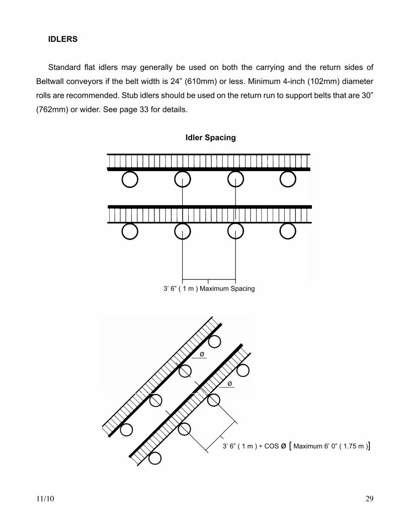
IDLERS
Standard flat idlersmay generally be used on both the carrying and the return sides of
Beltwall conveyors if the belt width is 24” (610mm) or less. Minimum 4-inch (102mm) diameter
rolls are recommended. Stub idlers should be used on the return run to support belts that are 30”
(762mm) or wider. See page 33 for details.
Idler Spacing
3’ 6” ( 1 m ) Maximum Spacing
3’ 6” ( 1 m ) ÷ COS ø [ Maximum 6’ 0” ( 1.75 m )]

11/1030
IDLER BACKING HEIGHT
wolla ot thgieh gnikcab reldI :ETON acol ot edis nruter te 1/4 x sidewall
,enil tnegnat woleb thgieh not to .) mm 46 ( ”2/1-2 deecxe
NOTE: Idler backing height to maintain return side level with tangent line in any section leading to a downturn deflection point.
TANGENT LINESTANGENT LINES
TANGENT LINES

11/10 31
IDLER BACKING HEIGHT (Continued)
t
NOTE: Idler backing height to allow return side to locate 1/4 x sidewall height below tangent line, not to exceed 2-1/2” ( 64 mm ).
NOTE: Idler backing height to allow return side to locate 1/4 x sidewall height below tangent line, not to exceed 2-1/2” ( 64 mm ).
TANGENT L
INES
TANGENT LINES

11/1032
RETURN IDLER LOCATION ADJACENT TO DRIVE OR RETURN BEND PULLEY
Neverlocatedaflatreturnidlercloserthan3feet(1m)“downstream”fromadrivepulleyor
a return bend pulley to prevent possible “whipsawing” or “buckling” against the idler.
3’ 0” Minimum(1 m)
3’ 0”
Minimum
(1 m)
3’ 0” Minimum(1 m)
3’ 0” Minimum(1 m)

11/10 33
Stub idlers are recommended for use on the return side for belts 30” (762mm) and wider. It
is preferred that the cans be compounded from urethane, or at least urethane lagged, to offer
greater protection to the belt should the idler bearing become frozen.
Stub Idler Section on Return Side
Notethestubidlersaregenerallyangleddowntowardthebeltcentertofacilitatethemodified
catenary shape of the suspended cross-rigid belt.
Stub idlers should not be angled down in any section immediately prior to a downturn
deflectionwheel,suchasthereturnsideofthedischargesectionofanS-shapedsystem.Stub
idlers are level from side to side to prevent any inadvertent outward canting of the sidewall that
mayresultininterferencewiththedeflectionwheel.
Consideration must be given to total idler load when sizing; include not only belt load but also
dynamic loads due to product loading, impact due to product accumulation on idler rolls, etc.
Idler design considerations include:
Bearing Design - Overhung double bearing type idlers may be used for most applications.
Double bearing (inboard/outboard) type idlers should be used for extremely heavy loadings.
Overhung Bearings Inboard / Outboard Bearings
11/1034
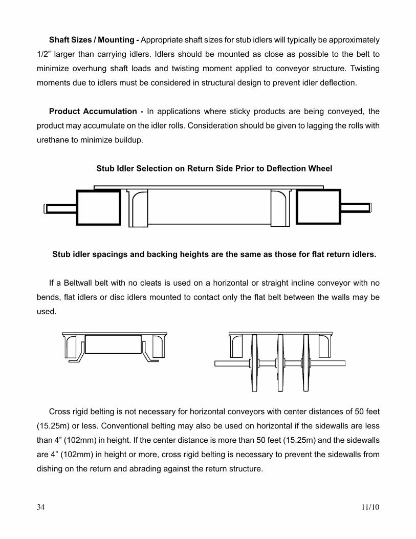
Shaft Sizes / Mounting - Appropriate shaft sizes for stub idlers will typically be approximately
1/2” larger than carrying idlers. Idlers should be mounted as close as possible to the belt to
minimize overhung shaft loads and twisting moment applied to conveyor structure. Twisting
momentsduetoidlersmustbeconsideredinstructuraldesigntopreventidlerdeflection.
Product Accumulation - In applications where sticky products are being conveyed, the
product may accumulate on the idler rolls. Consideration should be given to lagging the rolls with
urethane to minimize buildup.
StubIdlerSelectiononReturnSidePriortoDeflectionWheel
Stubidlerspacingsandbackingheightsarethesameasthoseforflatreturnidlers.
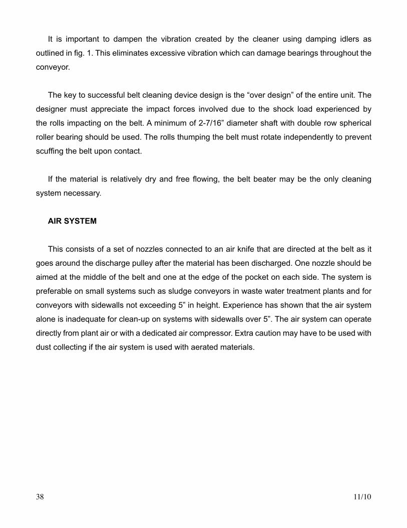
If a Beltwall belt with no cleats is used on a horizontal or straight incline conveyor with no
bends,flatidlersordiscidlersmountedtocontactonlytheflatbeltbetweenthewallsmaybe
used.
Cross rigid belting is not necessary for horizontal conveyors with center distances of 50 feet
(15.25m) or less. Conventional belting may also be used on horizontal if the sidewalls are less
than 4” (102mm) in height. If the center distance is more than 50 feet (15.25m) and the sidewalls
are 4” (102mm) in height or more, cross rigid belting is necessary to prevent the sidewalls from
dishing on the return and abrading against the return structure.

11/10 35
SLIDER BEDS
SliderbedreturnsarepermissibleonlywithUHMWcleats.TheUHMWcleatshouldbebolted
into a rubber cleat base vulcanized to the base belt. The cleat should extend 1/2” (13mm) higher
thanthesidewalltopreventanycontactofthesidewallandthereturnpan.AUHMWlinershould
beusedonthereturnpantoreduceabrasionoftheUHMWcleat.TheUHMWcleatmustbe
replaced when it abrades to the same height as the sidewall. If the cleats are not replaced at this
point, sidewall abrasion will cause premature sidewall failure.
GUIDE/TRAINING IDLERS
If a conveyor is level and true, the belt will track satisfactorily with no external guiding devices.
However, it is of course recognized there are those operating conditions that do indeed dictate
theuseofsomeformoftrainingdevice.Wheneverguiderollsortrainingdevicesareused,itis
absolutely necessary to understand that these units must be considered only as a secondary
and never as a primary means of training - there is no substitute for a level and true conveyor.
Operating personnel must be made aware that immediately upon the observance of the guide
or training devices becoming active, there is another condition occurring elsewhere to make the
beltmistrackatthatpoint.Thaterrantconditionmustimmediatelybeidentifiedandcorrected
to prevent the training device from exerting force on the belt for an extended period of time and
possibly causing belt damage. The guide idlers should have 1/8” (3mm) less clearance from the
beltedgesthantherecommendedclearancesforthesidewallsfromthedeflectionwheelsand
stub idlers.
If guide or training rolls are necessary, the optimum placement should be just prior to any bend
section, no nearer to the bend than two times the belt width, or 8 feet (2.4m), whichever is less,
wherever possible. Guide idlers should be either pneumatic tires or a minimum of 6” (152mm)
diameter cans compounded from rubber or urethane to protect the belt edge. Additionally, using
a pair of guide idlers on each side will minimize the point stress to the belt edge should it make
contact with the guide idlers.

11/1036
Optimum Guide Roll Placement
TAKE-UP ARRANGEMENTS
Beltwall recommends locating the take-up arrangement at the tail of the system. Screw-type
take-ups are the most common, but gravity and hydraulic units are employed with carriage-
mounted tail pulleys on systems of 200 feet or more in pulley center distance.
Although Beltwall cross-rigid belts have a very low stretch factor, it is still advisable to allow 2
to 3 percent of the total conveyor centers for take-up travel to facilitate the ease of installation and
splicing,aswellasprovidinganadditionalmarginofsafetyinspecifyingthefinalbeltlength.
INSPECTION/ACCESS PANELS
In order to allow inspection and/or service of all moving parts, inspection doors or some form
of easy access should be located at all pulleys, idlers and bend sections. Failure of mechanical
parts may cause immediate and severe belt damage. Inspection doors allow regular preventative
maintenance to avoid this situation.

11/10 37
BELT CLEANING
There are two locations on an S-shaped corrugated sidewall belt conveyor that may need
regular cleaning, (A) the head or drive section and (B) the lower return bend area and space
between it and the pulley.
CLEANING AT THE HEAD SECTION
A small quantity of moist material may stick to the belt after discharge at the head pulley. If
the material is not cleaned off the belt, it may build up in the lower area impending the belt travel
causing damage to the sidewalls and belt tracking problems.
Currently, the following methods of clean-up for the head end are available.
Standard Rotating Belt Cleaner
One effective method for cleaning a Beltwall belt is the use of a rotating belt cleaning device.
Commonly called “belt beaters” or “belt thumpers”, the units are used to impact the belt as little
as possible and still affect carry-over material discharge. The most common error in placement
and operations involves excessive impact that may cause belt damage or unwanted system
noiseandvibration.Generally,1/4”to3/8”deflectionissufficienttosatisfactorilydischargethe
material.(Seefig.1)
The rotating belt beater should be placed as close to the discharge pulley as possible and
run at a recommended speed of 500 RPM. Adjustments in both the vertical and horizontal planes
isdesired tooptimize thedischargeand toallow forminormodification in casesympathetic
harmonic frequency vibrations occur.
Figure 1. Rotating “Belt Beater” is a common method of cleaning beltwall belts at the head section of the conveyor.
11/1038
It is important to dampen the vibration created by the cleaner using damping idlers as
outlinedinfig.1.Thiseliminatesexcessivevibrationwhichcandamagebearingsthroughoutthe
conveyor.
The key to successful belt cleaning device design is the “over design” of the entire unit. The
designer must appreciate the impact forces involved due to the shock load experienced by
the rolls impacting on the belt. A minimum of 2-7/16” diameter shaft with double row spherical
roller bearing should be used. The rolls thumping the belt must rotate independently to prevent
scuffingthebeltuponcontact.
If thematerial is relativelydryand freeflowing, thebeltbeatermaybe theonlycleaning
system necessary.
AIR SYSTEM
This consists of a set of nozzles connected to an air knife that are directed at the belt as it
goes around the discharge pulley after the material has been discharged. One nozzle should be
aimed at the middle of the belt and one at the edge of the pocket on each side. The system is
preferable on small systems such as sludge conveyors in waste water treatment plants and for
conveyors with sidewalls not exceeding 5” in height. Experience has shown that the air system
alone is inadequate for clean-up on systems with sidewalls over 5”. The air system can operate
directly from plant air or with a dedicated air compressor. Extra caution may have to be used with
dust collecting if the air system is used with aerated materials.
11/10 39
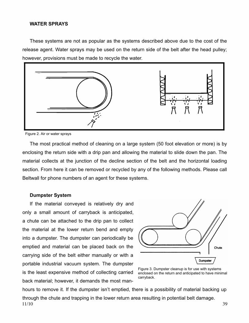
WATER SPRAYS
These systems are not as popular as the systems described above due to the cost of the
releaseagent.Waterspraysmaybeusedonthereturnsideofthebeltaftertheheadpulley;
however, provisions must be made to recycle the water.
The most practical method of cleaning on a large system (50 foot elevation or more) is by
enclosing the return side with a drip pan and allowing the material to slide down the pan. The
material collects at the junction of the decline section of the belt and the horizontal loading
section. From here it can be removed or recycled by any of the following methods. Please call
Beltwall for phone numbers of an agent for these systems.
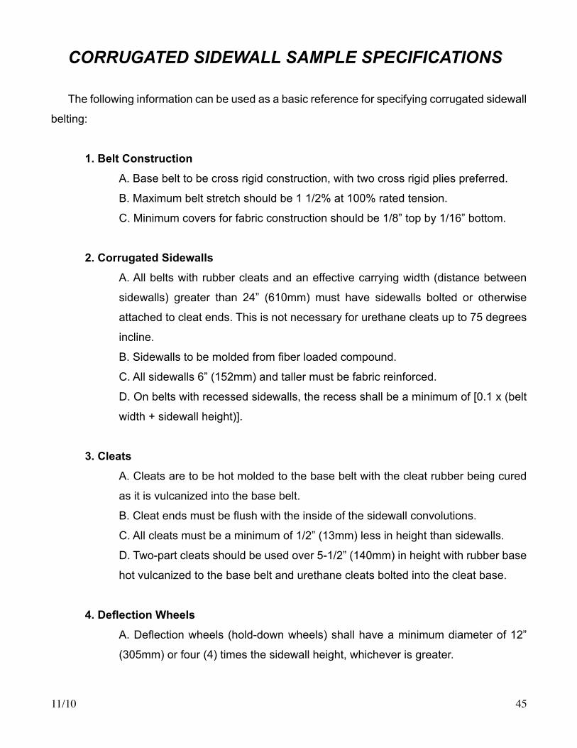
Dumpster System
If the material conveyed is relatively dry and
only a small amount of carryback is anticipated,
a chute can be attached to the drip pan to collect
the material at the lower return bend and empty
into a dumpster. The dumpster can periodically be
emptied and material can be placed back on the
carrying side of the belt either manually or with a
portable industrial vacuum system. The dumpster
is the least expensive method of collecting carried
back material; however, it demands the most man-
hours to remove it. If the dumpster isn’t emptied, there is a possibility of material backing up
through the chute and trapping in the lower return area resulting in potential belt damage.
Figure 2. Air or water sprays
Figure 3. Dumpster cleanup is for use with systems enclosed on the return and anticipated to have minimal carryback.

11/1040
Stationary Industrial Vacuum
If more carryback is anticipated than practical for a dumpster, a stationary recirculating
vacuum system can be used. The system can be connected to a chute for pulling the material out
of the lower bend area with the same unit
returning the material back onto the belt.
This type of system has the advantage of
being very low in maintenance and is less
costly than a portable industrial vacuum
system. A derivative of this system is
using the same dust collector as used on
the system for dust control. However, if
the carryback is great enough, it may take
an unacceptable amount of man hours
emptying bag houses. This type of system
is not practical with heavy materials (over 75 lbs/ft3), wet/sticky materials, or with materials
containing lumps.
Screw reclaim system
Another method of cleaning at the lower return is a combination of two screw conveyors;
one removes material from the lower return
area through a chute in the same position as
the chute in the same position as the chute
for the industrial vacuum described above,
another screw conveys back to the carrying
side of the belt. If the lower horizontal section
is longer than normal, a third screw can be
added along the length of this section. (See
Figure 5 above)
Figure 4. Vacuum cleanup systems handle more carryback than most dumpster systems and require little maintenance.
Figure 5. Screw reclaim system.

11/10 41
Recirculating Drag Conveyor
Another alternate clean-up method is a drag conveyor extending beyond the tail pulley,
elevating the material en masse, and discharging back on the belt. This system has the
disadvantage of being more expensive
than either the screw or stationary industrial
vacuum and normally experiences greater
maintenance cost. (See Figure 6)
Note: Some customers have tried a belt
conveyor slave driven from the lower return
bend around the tail pulley discharging the
material back on the carrying side of the
belt. Beltwall does not recommend this type of cleanup system since the tension to slave drive
the belt is different around the tail than it is at the lower return. Therefore, the greater pressure
around the tail causes the slave driven belt to crush the sidewalls resulting in premature sidewall
failure.
Circular Chain System
One more example of clean-up involves
cutting a section out of a lower return pan
and chuting the material into a circular chain
conveyorwithflightsthatrotatethematerial
to a discharge point above the conveyor, into
a chute, which places the material back onto
the carrying side of the belt. A small screw
conveyor can be used to feed the material
from the lower return bend pulley to the
circular chain.
Figure 6. A recirculating drag conveyor starting beyond the lower return.
Figure 7. Two views of a circular chain system.
Side View
End View

11/1042
Figure 8. View of a Pulley Shield
A
SECTION A-A
A
Enlarged View
Return Bend Pulley Shield
V-plows are mounted on the return side
of the belt prior to the lower return bend.
They remove destructive material from the
underside of the belt and discharge it to
both sides of the conveyor. This prevents
material from becoming trapped between
the pulley and belt, protects the belt from
puncture damage, and reduces build-up
on the pulley thereby reducing alignment
problems.
Recess Area Scraper
The scrapers are mounted in the
recessareapriortotheUpturndeflection
wheels. Positioned to lightly contact the
top cover and divert material off of the
belt, the scraper prevents material from
becoming “pinched” between the belt
anddeflectionwheel,thusprotectingthe
belt from damage. The inside edge of the
scraper should have the same offset from
thesidewallasthedeflectionwheel.The
scraper should be constructed of rubber
or urethane.
Figure 9. V iew of R ecess Area Scraper at Upturn DeflectionWheel

11/10 43
Cleat Spillage Plates
BeltwallCleatSpillagePlatesaredesignedtocontainsmall,granular,orfree-flowingmaterials
conveyed at incline angles greater than 75 degrees. Spillage plates are installed on each end
of the cleats, effectively blocking theadjacent sidewall convolutionandpreventing flowpast
the cleat into the following cleat pocket. Spillage plates are also occasionally used to prevent
product entrapment in the sidewall convolutions and subsequent carryback.
Shown above is a typical “C” cleat plate. Spillage plates also block extended
convolutions at the noseover, reducing product entrapment.

11/1044
Assistance and Drawing Review
Beltwall offers technical assistance and drawing review for mechanical components as a
standard service to all customers. Designers are strongly encouraged to utilize this resource
for the rapid return of information based on experience gained from thousands of successful
installations. Beltwall technical personnel are available for comments and review on all mechanical
aspects of the design, installation, and operation of any Beltwall.
System application recommendations, along with any other written or verbal information from Beltwall Division, Beltservice Corporation, is accurate and reliable. However, it is offered as a service only. No warranty is either expressed or implied, and Beltwall cannot assume any liability whatsoever regarding its use. The user of Beltwall products must determine for himself the suitability of such products and recommendations for his own purposes, or the specific purposes to which those products and recommendations may be applied.
11/10 45
CORRUGATED SIDEWALL SAMPLE SPECIFICATIONS
The following information can be used as a basic reference for specifying corrugated sidewall
belting:
1. Belt Construction
A. Base belt to be cross rigid construction, with two cross rigid plies preferred.
B. Maximum belt stretch should be 1 1/2% at 100% rated tension.
C. Minimum covers for fabric construction should be 1/8” top by 1/16” bottom.
2. Corrugated Sidewalls
A. All belts with rubber cleats and an effective carrying width (distance between
sidewalls) greater than 24” (610mm) must have sidewalls bolted or otherwise
attached to cleat ends. This is not necessary for urethane cleats up to 75 degrees
incline.
B.Sidewallstobemoldedfromfiberloadedcompound.
C. All sidewalls 6” (152mm) and taller must be fabric reinforced.
D. On belts with recessed sidewalls, the recess shall be a minimum of [0.1 x (belt
width+sidewallheight)].
3. Cleats
A. Cleats are to be hot molded to the base belt with the cleat rubber being cured
as it is vulcanized into the base belt.
B.Cleatendsmustbeflushwiththeinsideofthesidewallconvolutions.
C. All cleats must be a minimum of 1/2” (13mm) less in height than sidewalls.
D. Two-part cleats should be used over 5-1/2” (140mm) in height with rubber base
hot vulcanized to the base belt and urethane cleats bolted into the cleat base.
4.DeflectionWheels
A.Deflectionwheels(hold-downwheels)shallhaveaminimumdiameterof12”
(305mm) or four (4) times the sidewall height, whichever is greater.

11/1046
B.Innerdeflectionwheelsarenotrecommended.
C.Deflectionwheelsshallhaveafacewidthnolessthanthesidewallrecess.
D.Wheelsshallbespacedtoprovidesidewallclearanceoneachsideequalto3/4”
or .15 x sidewall recess; whichever is greater; with maximum of 2”.
E.Inneredgeofthedeflectionwheelshouldcontaina3/8”(10mm)radius.
5. Idlers
A. Idler spacings on both carrying and return sides shall be a maximum of 3’6”
(1m) on horizontal sections, and a maximum of [3’6” (1m) divided by COS (angle
of incline)] or 6’ (1.35m), whichever is less, on all inclined sections.
B. Stub idlers must be used on the return run on all systems with a belt width of
30” (762mm) and greater.
C. Idler diameter shall be 4” (102mm) minimum.
6. If self-cleaning pulleys are required on the tail, spiral wing pulleys may be used, but
never standard wing pulleys.
7. Standard snub pulleys should never be used. If snubbing is necessary, deflection
wheels should be used. Consult Beltwall.
8.Allpulleysshouldbeflatfaced,trapezoidal,orcurvedcrown.Centercrownpulleysare
never recommended with cross rigid belts.
9. If rollers are used for the noseover, there should be a minimum of 1 for every 10
degrees of incline plus 1 additional roller. Spacing of the rollers should be a maximum of
1.5 x roller diameter. Shaft sizing is to be based upon the resultant load.

11/10 47
Design Information Data Sheet
A C
BE
F°
D
DESIGN INFORMATION -- ALL BELTSMax. Temperature:
Oily Condition? Yes N o
Moisture? %
Belt Width Preference?
Belt Speed Preference?
CONFIGURATION
A
BE
C
F°
D
BE
A
F°
C
B
CF°
E
EXISTING BELTBelt Length
Belt Width (BW)
Sidewall Height (H)
Sidewall Recess (R)
Sidewall Width (SW)
Effective Width (EW)
Belt Speed
Belt Type
Covers
Cleat Height
Cleat Type
Cleat Spacing
Pulley Dia.
End Prep.
FIGURE 1 FIGURE 2 FIGURE 3 FIGURE 4 FIGURE 5
FIGURE NO.AB
CD
EF °
Material:
Required Capacity: (STPH)
Density: (lbs./cu. ft.)
Angle of Surcharge: °
Lump Size: Min. Max.
EW
C
BW
SWRR
H
Cleat Types
"I "S"" "C"

11/1048

11/10 49
Installation

11/1050
INTRODUCTION
The installation of a Beltwall belt must be carefully planned. Conventional methods of handling
andstringingmaybeinsufficientforallbutshort,narrowconveyorswithlessthantwovertical
bends.
Due to the unique shape, weight, and value of Beltwall belting, it is extremely important that
proper methods and equipment be utilized. Beltwall has prepared these suggestions to assist in
the successful installation for your application.
BELT STORAGE
For proper protection, Beltwall belting should be stored in its original shipping crate or
container until ready for installation.
Normally, the belts will be festooned back and forth along the length of the crating or container
inanaccordionfashion(Figure1).Thebeltwillbepackagedatthefactorywithsufficientsupports
to prevent settling or shifting during normal shipping and handling.
Packaging for Shipment and Storage
Figure 1
Please notify Beltwall if storage for longer than 1 year is anticipated.
Belts should be stored in dry, heated environments away from direct sunlight. Extreme
temperature variations can have an adverse effect on a belt over long periods of time. The ideal
storage range is between 50°F (10°C) and 70°F (21°C).
11/10 51
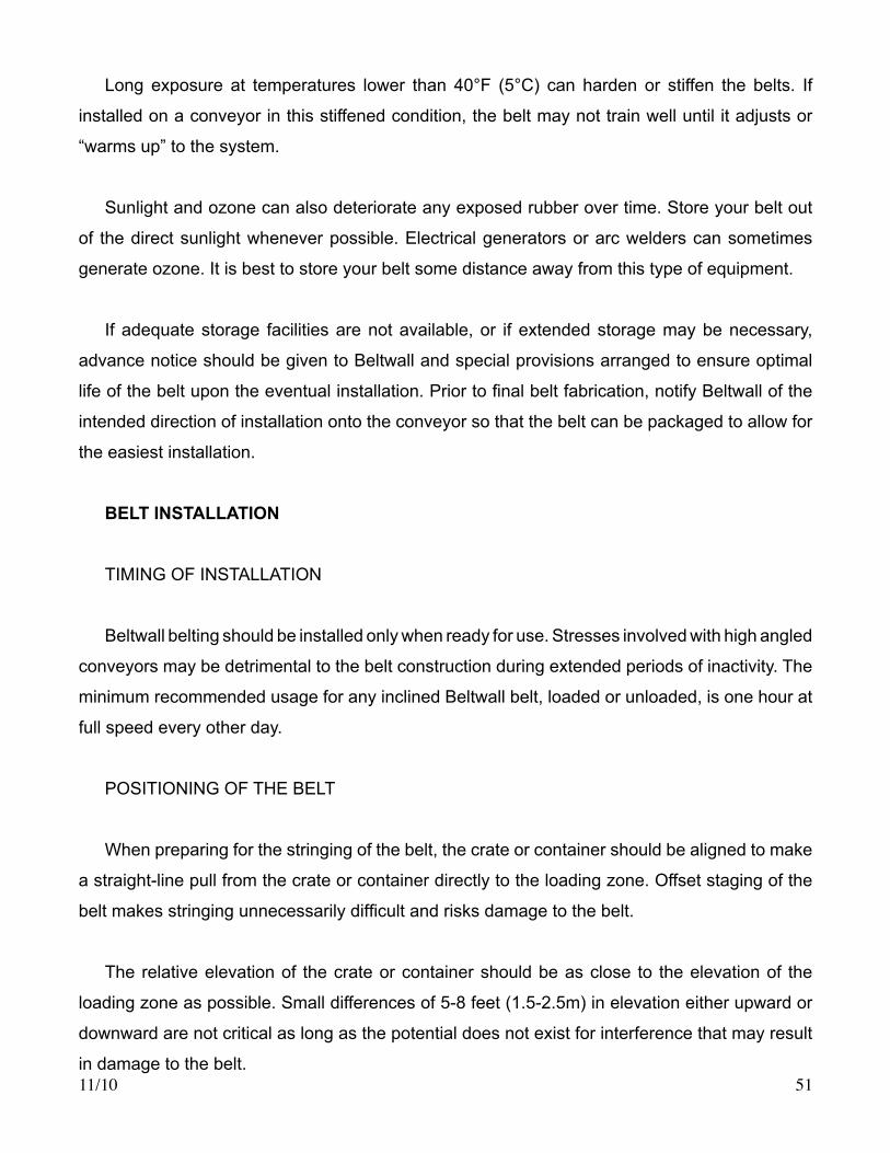
Long exposure at temperatures lower than 40°F (5°C) can harden or stiffen the belts. If
installed on a conveyor in this stiffened condition, the belt may not train well until it adjusts or
“warms up” to the system.
Sunlight and ozone can also deteriorate any exposed rubber over time. Store your belt out
of the direct sunlight whenever possible. Electrical generators or arc welders can sometimes
generate ozone. It is best to store your belt some distance away from this type of equipment.
If adequate storage facilities are not available, or if extended storage may be necessary,
advance notice should be given to Beltwall and special provisions arranged to ensure optimal
lifeofthebeltupontheeventualinstallation.Priortofinalbeltfabrication,notifyBeltwallofthe
intended direction of installation onto the conveyor so that the belt can be packaged to allow for
the easiest installation.
BELT INSTALLATION
TIMINGOFINSTALLATION
Beltwall belting should be installed only when ready for use. Stresses involved with high angled
conveyors may be detrimental to the belt construction during extended periods of inactivity. The
minimum recommended usage for any inclined Beltwall belt, loaded or unloaded, is one hour at
full speed every other day.
POSITIONINGOFTHEBELT
Whenpreparingforthestringingofthebelt,thecrateorcontainershouldbealignedtomake
a straight-line pull from the crate or container directly to the loading zone. Offset staging of the
beltmakesstringingunnecessarilydifficultandrisksdamagetothebelt.
The relative elevation of the crate or container should be as close to the elevation of the
loading zone as possible. Small differences of 5-8 feet (1.5-2.5m) in elevation either upward or
downward are not critical as long as the potential does not exist for interference that may result
in damage to the belt.

11/1052
The recommended, and certainly most common loading zones are at the tail or along the
lower horizontal section. Any plans for the erection of surrounding structural members, installation
of machinery, or assembly of conveyor components and covers should be scheduled to allow
for the location of the belting in this manner. In the event this preferred method is not practical,
the location of the belting for installation should allow for the adherence to these guidelines as
closely as possible, while remembering that the safest, fastest, and most economical location
for the splicing of the belt will be at the section with the lowest belt tensions - usually the loading
zone as described above.
CONVEYORALIGNMENT
The following items must be checked to ensure optimum belt performance:
A. The conveyor must be true relative to the center line.
B. The conveyor must be level from side to side.
C.Allcarryingandreturnidlers,deflectionwheelsandpulleysmustbesquarewiththe
frame. In addition, they must be perpendicular to the belt center line and parallel to one another.
D.Sufficientclearancemustbeprovidedonbothsides,underandbelowthehead,tail,
and bend sections.
E. Belt ends need to be examined to make sure they are squared.
F. To assure alignment of items A, B, and C, a survey instrument may be used to sight
a straight line parallel to direction of belt travel. Having completed this, make sure the
axesofpulleys,deflectionwheels,andcarryingandreturnidlersareperpendiculartothatline.
HANDLINGANDSECURINGBELTDURINGINSTALLATION
Remove any banding and packaging necessary to allow free access to the belt. Extreme care
should be given to prevent the binding or interference of the belt, sidewalls, or cleats with any of the
supports or braces used for packaging. Be aware there may be bracing hidden inside the walls that
cannot be seen from outside the crate or container. Determine the location of all packing materials prior
to any belt transfer to allow for the simultaneous removal of the packaging as each layer is lifted. Do
not remove the lower levels of bracing until necessary in order to continue providing support as long as
possible.

11/10 53
To avoid inadvertent damage, protect the belt from any sharp bends or folds at all times
during handling. Never place excessive weight on unsupported sections of belt or sidewall.
Supporttheloopsattheendofeachlayerwithsufficientlylargebendstopreventkinkingasyou
advance the belt.
There are a number of ways to pull/place the Beltwall belting onto the conveyor:
A. Thread a rope or cable opposite the direction of belt travel around the idlers and pulleys,
then link the rope or cable to the new belt by means of a lead plate or belt clamp to evenly
distributethetensionoverthewidthofthebeltfordrawingthebeltintoitsfinalposition.
B. Attach the new belt to the end of the old belt which has been cut for replacement and
use the old belt to pull the new belt into place.
C. Pull the belt in place by hand.
* Method A is the most preferred of all those available.
Only the smallest of Beltwall belts can be managed by hand onto the conveyor. Due to the
weight and length involved, most belts require the use of a hoisting source such as a crane, hoist,
puller, or vehicle with a winch. Additional lifting equipment is advised to aid in the simultaneous
lifting and pulling as the belt is gradually drawn from the crate or container to the loading zone
andfeed-inpointontotheconveyoraroundtoitsfinalpositionreadyforsplicing.(Figure2).
Lifting and Installation Equipment
Figure 2
11/1054
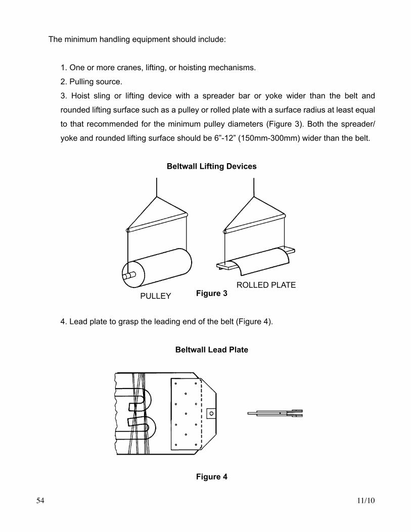
The minimum handling equipment should include:
1. One or more cranes, lifting, or hoisting mechanisms.
2. Pulling source.
3. Hoist sling or lifting device with a spreader bar or yoke wider than the belt and
rounded lifting surface such as a pulley or rolled plate with a surface radius at least equal
to that recommended for the minimum pulley diameters (Figure 3). Both the spreader/
yoke and rounded lifting surface should be 6”-12” (150mm-300mm) wider than the belt.
Beltwall Lifting Devices
Figure 3
4.Leadplatetograsptheleadingendofthebelt(Figure4).
Beltwall Lead Plate
Figure 4
PULLEYROLLEDPLATE

11/10 55
5. Holding clamp for providing a positive grip if necessary at mid-sections of the belt. The
holding clamp should be fabricated to straddle the sidewall and have a curved lifting surface like
the hoist sling or lifting device (Figure 5).
WARNING!!! If ordinary slings, chokers, or C-clamps are used instead of the appropriate
lifting devices and holding clamps, there is a greatly increased likelihood of permanent
belt damage!
Beltwall Holding and Lifting Clamp
Figure 5
6. Pulling cable or rope.
7. Feed table and/or support rollers for supporting the weight of the belt without dragging
from the crate or container to the loading zone. (Figure 2)
8. Guide sheaves for directing the pulley cable from the conveyor to the pulling source
and for directing the pulling cable through the upturn and downturn bend areas (Figure 2) without
damaging the shafting or putting undue stress on the belt. A special drum may also be used to
guide the pulling cable over the upturn and downturn shafts.
9. Protective sheave to protect pulley lagging as the pulling cable passes over the pulley
surfaces.
10.Feedrolls,similarindesigntodeflectionwheelassemblies,mountedonaframeand
temporarily mounted on the conveyor structure to guide the belt into the framework protecting
both the belt and the conveyor housing (Figure 2).
11. Tape or clip to anchor any excess sidewall lengths to the belt during stringing.

11/1056
DIRECTIONOFINSTALLATION
As previously discussed, the preferred method for stringing the belt is to pull the belt from the
tailorhorizontalloadingsectionalongtheconveyorprofileinthedirectionthebeltwilltravelin
operation (Figure 2).
It is understood some conveyors may not permit the preferred loading zone and installation
procedure. If feed-in is required from some other point, or if the belt is lowered from above the
conveyor, careful individual planning and study is absolutely necessary to ensure the proper
installation of Beltwall belting. In any case, the basic protection for the belt as outlined in these
instructions must still be carefully observed.
BELT SPLICING
Wheneverpossible,thebeltsplicingpointshouldbeatthelowerendoftheconveyor.This
permitstheconveyorstructuretosupportthebeltweightandsimplifiesinitialtensioningofthe
belt. Rigging for splicing the belt at any elevated point necessitates special belt clamping and
lashingprovisions.Sucharrangementsalsomakeitmoredifficult topulloutexcessslackso
the start-up setting of the take-up can be more accurately positioned to ensure the belt length
finishedontheconveyorisequaltothecalculatedlengthsupplied.
For hot vulcanized belt splices, the following provisions are required:
A. Access to both sides of the belt from a catwalk or platform.
B. At least 16 feet (5m) of work area along the belt length to permit fold back for preparing
the bottom side of the splice overlap.
C. Overhead clearance to permit workers to stand erect when rigging the vulcanizer and
related equipment.
D. Shelter from weather and temperature extremes.
E. Electric power supply for vulcanizer tools.
F.Liftingassistanceifvulcanizingequipmentcannotbeshifteddirectlyfromthetruckbed
into splicing position.
For mechanical belt splices, DO NOT TRIM the belt edges in the mechanical fastener area. The
fasteners must extend across the full width of the belt. On a system with bends, all of the tension
mustbeabsorbedbytherecessportionofthebeltacrossthefacewidthofthedeflectionwheel.If
the belt edge is trimmed at the fastener, holding ability is lost causing fasteners to pull out.