filter design (1)
DESCRIPTION
Filter Design (1). Jack Ou ES590. Outline. Butterworth LPF Design Example LPF to HPF Conversion LPF to BPF Conversion LPF to BRF Conversion. Butterworth Filter. (Attenuation of the Butterworth filter). Avoid ripples in the passband . - PowerPoint PPT PresentationTRANSCRIPT
Filter Design (1)
Jack OuES590

Outline
• Butterworth LPF Design Example• LPF to HPF Conversion• LPF to BPF Conversion• LPF to BRF Conversion
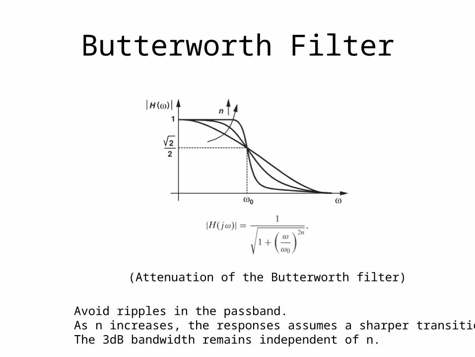
Butterworth Filter
Avoid ripples in the passband.As n increases, the responses assumes a sharper transition.The 3dB bandwidth remains independent of n.
(Attenuation of the Butterworth filter)
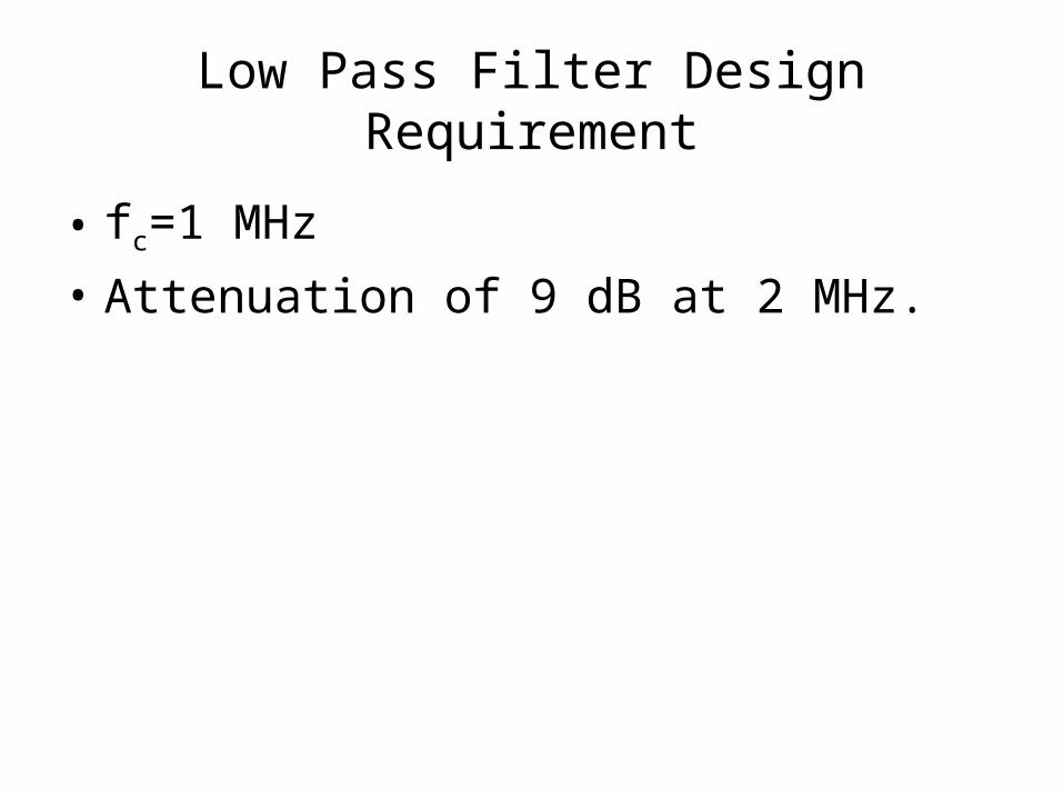
Low Pass Filter Design Requirement
• fc=1 MHz
• Attenuation of 9 dB at 2 MHz.
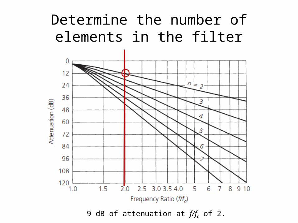
Determine the number of elements in the filter
9 dB of attenuation at f/fc of 2.

Low Pass Filter

Frequency and Impedance Scaling

Impedance Scaling

Simulation Results
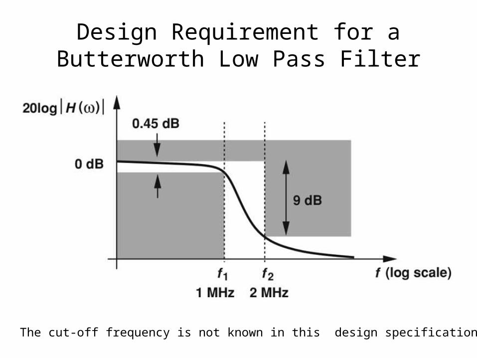
Design Requirement for a Butterworth Low Pass Filter
The cut-off frequency is not known in this design specification.

Design Process
Since f2=2f1, then n=3.
(fo=1.45 MHz)

Elementary Prototype Value
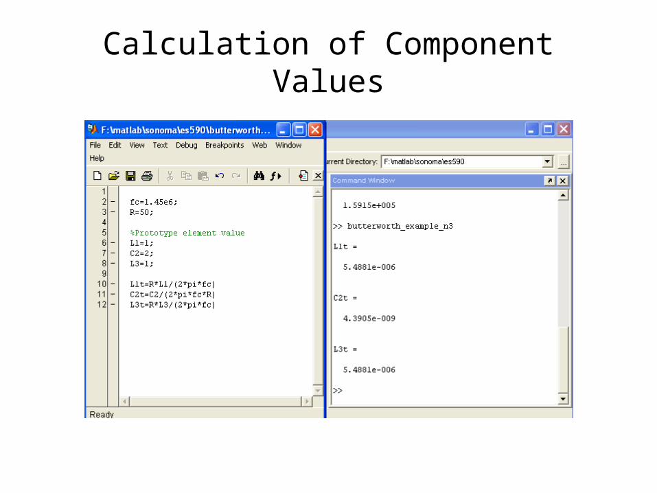
Calculation of Component Values

Simulation Results

LPF to HPF Conversion
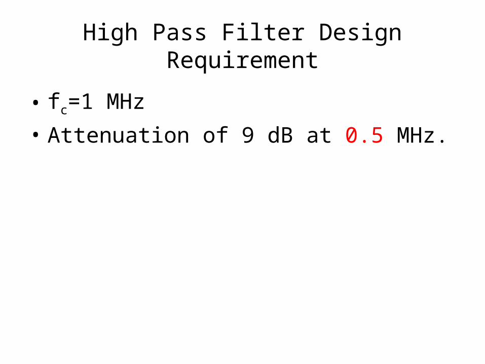
High Pass Filter Design Requirement
• fc=1 MHz
• Attenuation of 9 dB at 0.5 MHz.
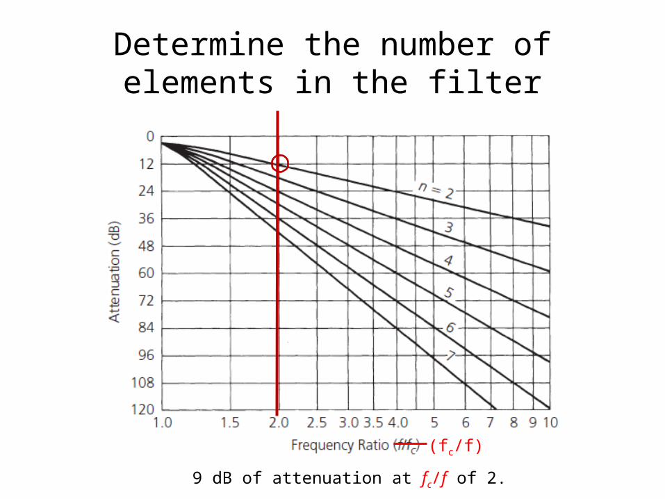
Determine the number of elements in the filter
9 dB of attenuation at fc/f of 2.
(fc/f)

Low Pass Filter
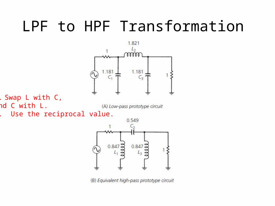
LPF to HPF Transformation
1. Swap L with C, and C with L.2. Use the reciprocal value.

Frequency and Impedance Scaling
(same as before)
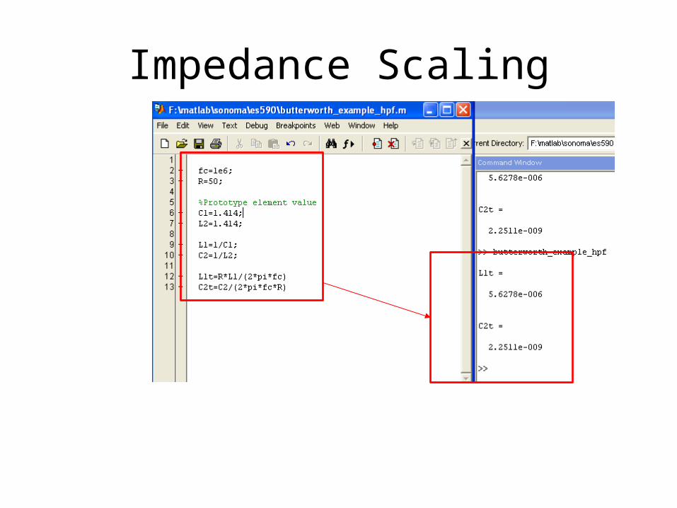
Impedance Scaling

HPF

LPF to BPF Conversion
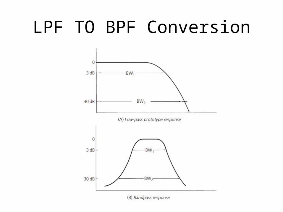
LPF TO BPF Conversion

Determine f3

Typical Bandpass Specifications
When a low-pass design is transformed into a bandpass design, the attenuation bandwidth ratios remain the same.

Determine n using f/fc
Transformation from LPF to BPF
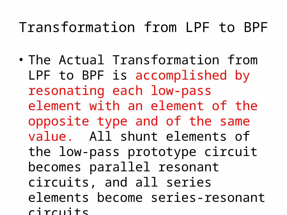
• The Actual Transformation from LPF to BPF is accomplished by resonating each low-pass element with an element of the opposite type and of the same value. All shunt elements of the low-pass prototype circuit becomes parallel resonant circuits, and all series elements become series-resonant circuits.

Transformation Example
Resonate each low-pass element with an element of the opposite type and of the same value.

Calculate Component Values

Fourth Order Butterworth Filter

Transformation
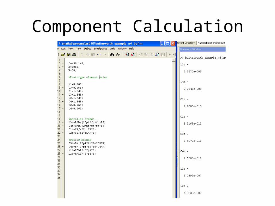
Component Calculation
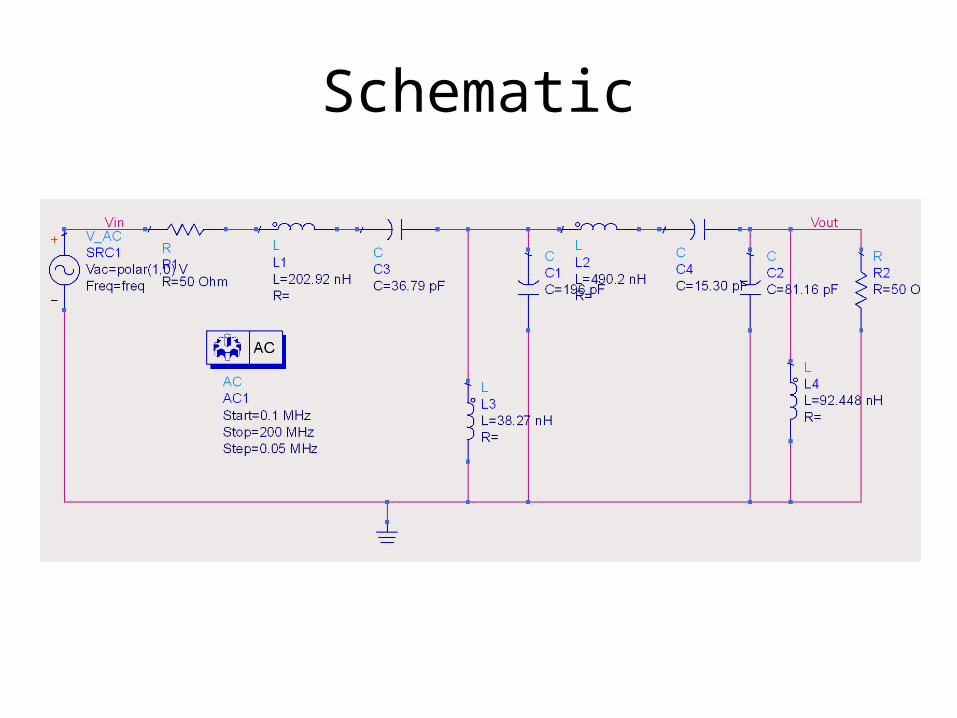
Schematic

Av on Log(f)

Av on Linear f
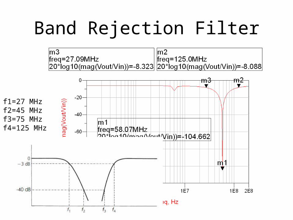
Band Rejection Filter
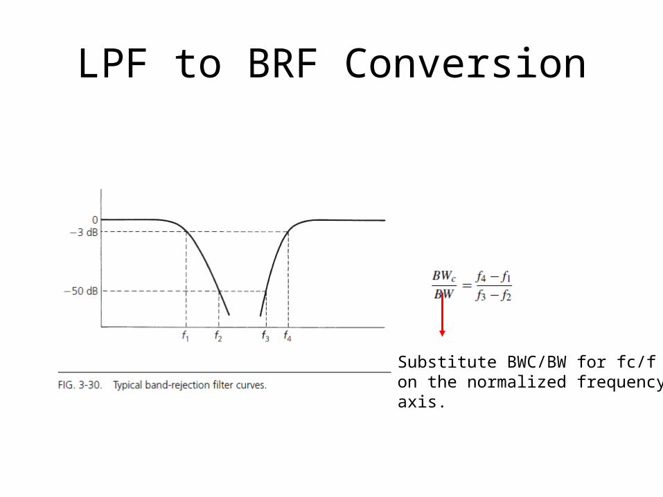
LPF to BRF Conversion
Substitute BWC/BW for fc/fon the normalized frequency axis.
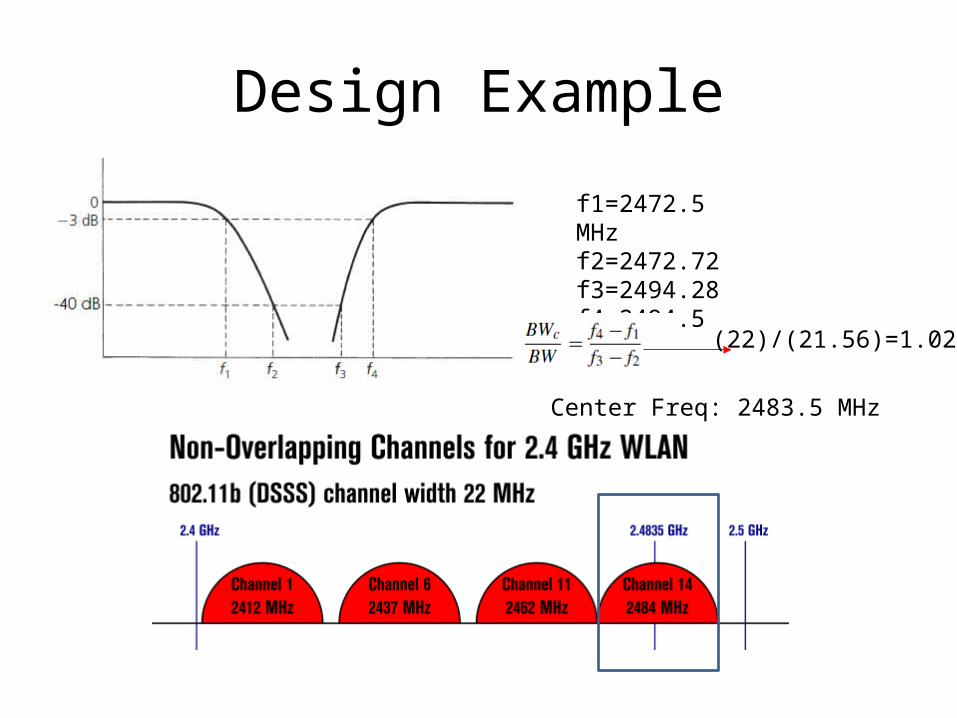
Design Example
f1=2472.5 MHzf2=2472.72f3=2494.28f4=2494.5 MHz (22)/(21.56)=1.0204
Center Freq: 2483.5 MHz
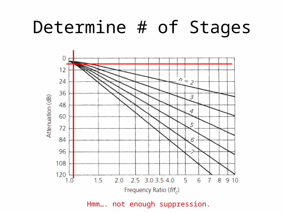
Determine # of Stages
Hmm…. not enough suppression.

Design Example
f1=27 MHzf2=45 MHzf3=75 MHzf4=125 MHz
(98)/(45)=2.1778Thus fc/f=2
Center Freq: 58.1 MHz

Determine # of Stages
fc/f

Transformation from LPF
Replace each shunt element with a shunt series resonant circuit.Replace each series element with a series parallel resonant circuit.Both elements in each of the resonant circuits have the same normalized value.
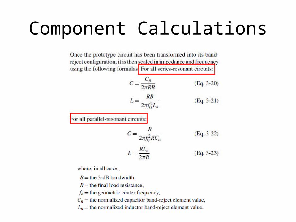
Component Calculations

Band Rejection Filter
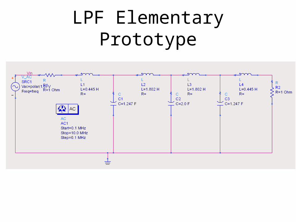
LPF Elementary Prototype
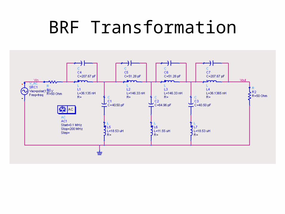
BRF Transformation
Band Rejection Filter
f1=27 MHzf2=45 MHzf3=75 MHzf4=125 MHz