filter control unit for speed-controlled pumps -...
TRANSCRIPT

Installation and Operating Instructions
-30 -Vario Filter control unit for speed-controlled pumps
Part no. 310.000.0535
Technical data:
Dimensions: 220mm x 220mm x 100mm
Operating voltage 230V/50Hz
Power consumption of control unit: approx. 5VA (depends on
operating mode)
Switching capacity: Pump: max. 8A / 1.0 kW (AC3)
Heater: max. 3A / 0.4 kW (AC3)
Dosing system: max. 3A / 0.4 kW (AC3)
Degree of protection: IP 40
Level sensors: Safety Extra Low Voltage (SELV)
Ambient temperature: 0-40°C
Air humidity 0-80% non-condensing
Connectable pumps
230V alternating-pump (rated current max. 8A)
Speck ECO-Touch pump
Speck ECO-Touch-Pro pump
Speck Badu-90-ECO-VS pump
Speck Badu-90-ECO-Motion pump
Pentair IntelliFlo pump
Pentair SuperFlo pump
Zodiac FloPro VS pump
UWE PMM pump

Operating instructions PC-30-Vario filter control unit Page: 2 (26)
Contents Operation: ....................................................................................................................................................... 3 Electrical connection ..................................................................................................................................... 4
Low-voltage lines ....................................................................................................................................... 4 Connecting the filter pump ......................................................................................................................... 4 Connecting a 230V AC filter pump without speed control ......................................................................... 5 Connecting a Speck ECO-Touch pump .................................................................................................... 5 Connecting a Speck ECO-Touch-Pro pump ............................................................................................. 5 Connecting a Speck ECO-VS pump .......................................................................................................... 6 Connecting a Speck Badu-90-ECO-Motion pump ..................................................................................... 6 Connecting a Pentair IntelliFlo pump ......................................................................................................... 7 Connecting a Pentair SuperFlo VS pump .................................................................................................. 7 Connecting a Zodiac FloPro VS pump ...................................................................................................... 7 Connecting the heater ............................................................................................................................... 8 Connecting the NR-12-TRS-2 water level controller ................................................................................. 8 Operating the PC-30-Vario without a NR-12-TRS-2 unit ........................................................................... 8 Connecting the dosing equipment ............................................................................................................. 8 Connecting the EUROTRONIK-10 for backwashing using a 6-way multiport valve .................................. 8 Operating the PC-30-Vario without a EUROTRONIK-10 unit .................................................................... 8 Connecting the sliding valves for backwashing ......................................................................................... 9 Connecting a swimming pool cover limit-switch ........................................................................................ 9 Temperature sensor .................................................................................................................................. 9 Frost protection ........................................................................................................................................ 10
Fuses............................................................................................................................................................. 10 ECO mode (energy saving mode) .............................................................................................................. 10 Controls on the front panel......................................................................................................................... 11
LCD display ............................................................................................................................................. 11 Operating mode selection ........................................................................................................................ 11 Pump indicator light ................................................................................................................................. 12 Heater indicator light ................................................................................................................................ 12 Heater switch ........................................................................................................................................... 12 Solar heater indicator light ....................................................................................................................... 12 Solar heater switch .................................................................................................................................. 12 Backwash using sliding valve .................................................................................................................. 12 Temperature selection ............................................................................................................................. 12 ECO temperature selection ..................................................................................................................... 13 Time setting ............................................................................................................................................. 13 Timer programming ................................................................................................................................. 13 ECO-timer programming ......................................................................................................................... 14 Backwash programming .......................................................................................................................... 15 Changing the language ............................................................................................................................ 15 Enabling frost protection mode ................................................................................................................ 15 INFO button ............................................................................................................................................. 15
Service Terminal .......................................................................................................................................... 16 Filter system operating mode .................................................................................................................. 16 Heater operating mode ............................................................................................................................ 17 Temperature at the solar sensor ............................................................................................................. 17 Temperature at the water sensor ............................................................................................................ 17 Set water temperature (target temperature) ............................................................................................ 17 Temperature reduction in Eco mode ....................................................................................................... 17 Switch-on temperature for solar heater ................................................................................................... 17 Switch-off temperature for solar heater ................................................................................................... 18 Temperature boost for swimming-pool water in solar mode ................................................................... 18 Maximum temperature ............................................................................................................................ 19 Heater hysteresis ..................................................................................................................................... 19 Solar heater hysteresis ............................................................................................................................ 19 Filter pump run-on after timed switch-off ................................................................................................. 20 Priority of temperature controller over timer ............................................................................................ 20 Priority for solar heater ............................................................................................................................ 21 Pump speed during solar operation ......................................................................................................... 21 Frost protection temperature (air temperature) ....................................................................................... 22 Frost protection temperature (water temperature) .................................................................................. 22

Operating instructions PC-30-Vario filter control unit Page: 3 (26)
Switch off pump during backwashing ...................................................................................................... 22 Pump operating time ............................................................................................................................... 23 ECO operating time ................................................................................................................................. 23 Heater operating time .............................................................................................................................. 23 Solar operating time................................................................................................................................. 23 Backwash counter (internal) .................................................................................................................... 23 Backwash counter (external) ................................................................................................................... 23 Forced switch-on of the NR-12-TRS-2 .................................................................................................... 23 EUROTRONIK-10 ................................................................................................................................... 24 locking...................................................................................................................................................... 24 Filter pump ............................................................................................................................................... 24 Solar system ............................................................................................................................................ 24 Heating .................................................................................................................................................... 25 Dosing equip. ........................................................................................................................................... 25 Backwash valve ....................................................................................................................................... 25 Clearwash valve ...................................................................................................................................... 25 Language ................................................................................................................................................. 26 Calibrating the temperature control system (sensor calibration) ............................................................. 26 Wiring diagram ........................................................................................................................................ 26
Pump stop ........................................................................................................................................................ 26 Backwash speed ............................................................................................................................................... 26 ECO speed ....................................................................................................................................................... 26 Mains 230V 50Hz ............................................................................................................................................... 26 Backwash valve 230V ........................................................................................................................................ 26 Clearwash valve 230V ........................................................................................................................................ 26 Solar actuator ................................................................................................................................................... 26 Winding protection switch .................................................................................................................................. 26 Heater 230V max.3A ........................................................................................................................................... 26 open ................................................................................................................................................................ 26 Limit switch for pool cover closed ............................................................................................................ 26
Operation:
The PC-30-Vario filter control unit is designed for timed on/off control of a 230V AC filter pump or speed-controlled filter pump (see wiring diagrams) according to a user-programmable control program.
Backwashing can be performed using a 6-way multiport valve and installed EUROTRONIK-10 controller or using slide valves and launched either manually or at a specific time or pressure.
While the filter pump is running, the swimming pool heater is controlled by the electronic temperature controller. During breaks in filter operation, the heater is automatically switched off by the internal interlock. The required water temperature for the swimming pool can be set on the front panel. The heater can also be switched off from here. A floating contact (terminals 26+27) and live contact
(terminal U2) are provided for the heater connection.
The microprocessor automatically enables the solar temperature controller when a solar temperature sensor is connected (part no. 3100000030). The free solar energy is then used as the preferred source for heating the swimming pool. The auxiliary heating is switched on automatically only when there is no energy being supplied by the solar heating system. If solar energy is available outside the filter operating periods (timer off), the solar heater will still start up along with the filter pump. The solar temperature sensor is suitable for use with direct flow solar collectors in which the swimming pool water flows directly through the absorbers. This control unit is not intended for use with other types of solar collectors. The
Operating instructions PC-30-Vario filter control unit Page: 4
absorber temperature must not exceed 80°C at the temperature sensor.
Connecting terminals are provided for an NR-12-TRS-2 electronic water level control unit (part no. 3030075020) for convenient automatic control of the water level in the swimming pool. This also protects the filter pump from any damage which might arise from running the filter installation without water.
The INFO button on the front panel can be used to change the user language and to retrieve various operating parameters.
Spare terminals are available for connecting additional devices such as chemical dosing equipment. Terminals 24+25 are floating contacts for custom use. The relay contact between terminals 24 and 25 is closed during the filter operating times and open outside the filter operating times. This contact is rated for a maximum voltage of 230V and a maximum current of 3A.
The connecting terminals for the winding protection switch are designed for connecting a thermal winding protection switch built into the filter-pump motor winding. If this switch opens, e.g. as a result of the motor winding getting too hot, the filter pump is switched off automatically along with the heater and dosing equipment. Once the winding protection switch closes after the motor winding has cooled down, the units are automatically switched back on. There is no need for a manual reset. The connecting terminals for the winding protection switch carry 230V.
Indicator lights in the front panel show when the filterpump and heater are running, allowing easy checking of the status.
ECO mode can be started automatically on closure of the swimming pool cover (limit-switch terminals 28 + 29).
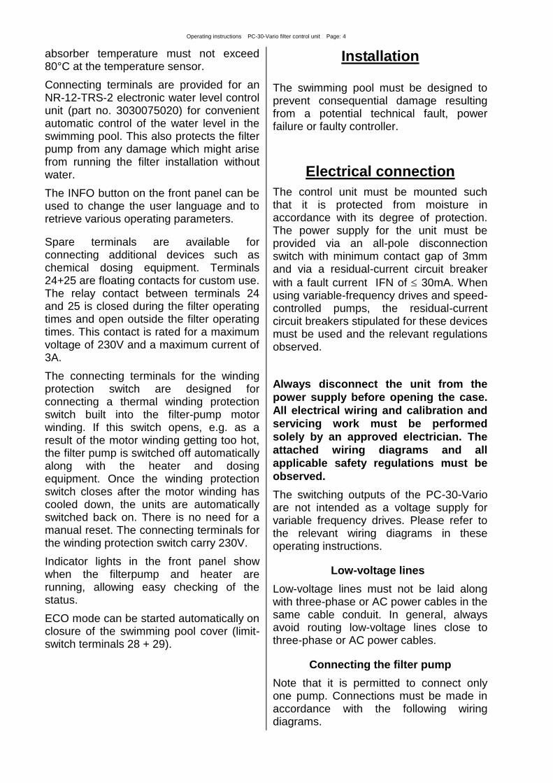
Installation
The swimming pool must be designed to prevent consequential damage resulting from a potential technical fault, power failure or faulty controller.
Electrical connection
The control unit must be mounted such that it is protected from moisture in accordance with its degree of protection. The power supply for the unit must be provided via an all-pole disconnection switch with minimum contact gap of 3mm and via a residual-current circuit breaker
with a fault current IFN of 30mA. When using variable-frequency drives and speed-controlled pumps, the residual-current circuit breakers stipulated for these devices must be used and the relevant regulations observed.
Always disconnect the unit from the
power supply before opening the case.
All electrical wiring and calibration and
servicing work must be performed
solely by an approved electrician. The
attached wiring diagrams and all
applicable safety regulations must be
observed.
The switching outputs of the PC-30-Vario are not intended as a voltage supply for variable frequency drives. Please refer to the relevant wiring diagrams in these operating instructions.
Low-voltage lines
Low-voltage lines must not be laid along with three-phase or AC power cables in the same cable conduit. In general, always avoid routing low-voltage lines close to three-phase or AC power cables.
Connecting the filter pump
Note that it is permitted to connect only one pump. Connections must be made in accordance with the following wiring diagrams.

Operating instructions PC-30-Vario filter control unit Page: 5
Connecting a 230V AC filter pump without speed control
The factory-inserted link between the two WPS terminals must be removed when connecting a pump fitted with a winding protection switch. If the pump does not have a winding protection switch, the link must remain screwed in place. These terminals are live and carry a mains voltage!
Connecting a Speck ECO-Touch pump
A Speck ECO-Touch pump can be connected directly to the PC-30-Vario unit. Connect the speed controller to terminals 15-20.
There must be a link inserted between the two WSK terminals (winding protection switch).
Always refer to the operating instructions for the pump.
Connecting a Speck ECO-Touch-Pro pump
A Speck ECO-Touch-Pro pump can be connected directly to the PC-30-Vario unit. Connect the speed controller to terminals 15-23.
A separate mains power supply must be provided for the pump. The power supply cannot be provided by the PC-30-Vario.
There must be a link inserted between the two WSK terminals (winding protection switch).
Always refer to the operating instructions for the pump.
Operating instructions PC-30-Vario filter control unit Page: 6
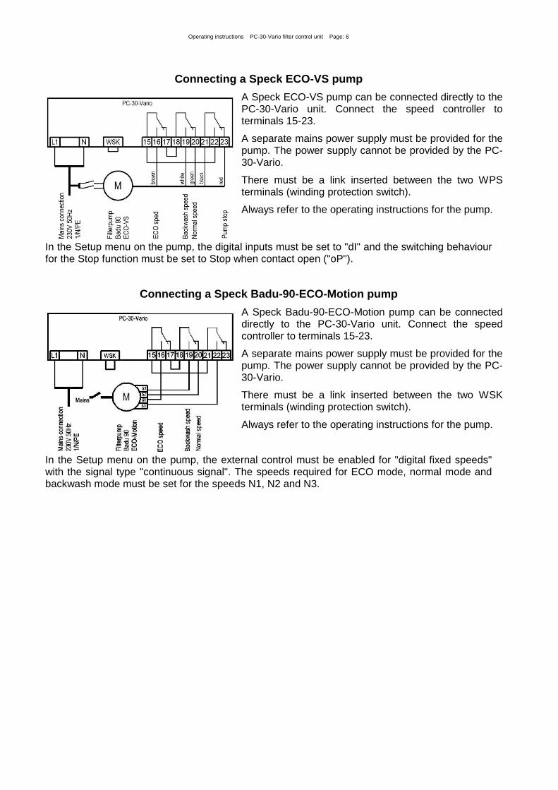
Connecting a Speck ECO-VS pump
A Speck ECO-VS pump can be connected directly to the PC-30-Vario unit. Connect the speed controller to terminals 15-23.
A separate mains power supply must be provided for the pump. The power supply cannot be provided by the PC-30-Vario.
There must be a link inserted between the two WPS terminals (winding protection switch).
Always refer to the operating instructions for the pump.
In the Setup menu on the pump, the digital inputs must be set to "dI" and the switching behaviour for the Stop function must be set to Stop when contact open ("oP").
Connecting a Speck Badu-90-ECO-Motion pump
A Speck Badu-90-ECO-Motion pump can be connected directly to the PC-30-Vario unit. Connect the speed controller to terminals 15-23.
A separate mains power supply must be provided for the pump. The power supply cannot be provided by the PC-30-Vario.
There must be a link inserted between the two WSK terminals (winding protection switch).
Always refer to the operating instructions for the pump.
In the Setup menu on the pump, the external control must be enabled for "digital fixed speeds" with the signal type "continuous signal". The speeds required for ECO mode, normal mode and backwash mode must be set for the speeds N1, N2 and N3.

Operating instructions PC-30-Vario filter control unit Page: 7
Connecting a Pentair IntelliFlo pump
An IntelliFlo pump can be controlled by the PC-30-Vario using the Pentair Intellicom controller. Connect the speed controller to terminals 15-20.
A separate mains power supply must be provided for the pump. The power supply cannot be provided by the PC-30-Vario.
There must be a link inserted between the two WSK terminals (winding protection switch).
Always refer to the operating instructions for the pump.
Connecting a Pentair SuperFlo VS pump
A SuperFlo VS pump can be controlled by the PC-30-Vario. Connect the speed controller to terminals 15-23.
A separate mains power supply must be provided for the pump. The power supply cannot be provided by the PC-30-Vario.
There must be a link inserted between the two WSK terminals (winding protection switch).
Always refer to the operating instructions for the pump.
Connecting a Zodiac FloPro VS pump
A Zodiac FloPro VS pump can be connected directly to the PC-30-Vario unit. Connect the speed controller to terminals 15-23.
A separate mains power supply must be provided for the pump. The power supply cannot be provided by the PC-30-Vario.
There must be a link inserted between the two WSK terminals (winding protection switch).
Always refer to the operating instructions for the pump.
On the pump, the speed controller must be connected to the designated terminals on the back of the user interface. The speeds required for ECO mode (level 1), normal mode (level 2) and backwash mode (level 3) must be assigned to speed levels 1 to 3.

Operating instructions PC-30-Vario filter control unit Page: 8
Connecting the heater
The terminal U2 is provided for the swimming pool heater. This output supplies 230V and is rated for a maximum load of 3A.
In addition, a floating contact is provided at terminals 26+27 (e.g. for controlling the boiler). This contact is rated for a maximum load of 230V, 3A.
An 230V solar actuator can be connected to terminals U5 and U6 for operating the solar heater. When solar heating is operating, the mains voltage is applied to terminal U6 and no voltage is applied to terminal U5.
Connecting the NR-12-TRS-2 water level controller
PC-30-Vario
NR-12-TRS-2
11 12 13 14
11 12 13 14
Water level control unit
A 4-wire connection is required for connecting the NR-12-TRS-2
water level controller. The wires must not be swapped over, i.e. they must be connected to the same terminal at each end. The NR-12-TRS-2 additionally requires a separate power supply.
Operating the PC-30-Vario without a NR-12-TRS-2 unit If the PC-30-Vario is intended to be operated without an NR-12-TRS-2 unit, terminals 13 and 14 must be connected together (with a link). Disconnect the connecting cable before doing so. The four terminals are live and carry a mains voltage.
Connecting the dosing equipment
PC-30-Vario
24 25
Dosing system
(floating contact)
max. 230V / 3A
A floating output is provided at terminals 24+25 for connecting the dosing equipment.
The contacts are rated for a maximum load of 230V, 3A.
Connecting the EUROTRONIK-10 for backwashing using a 6-way multiport valve
PC-30-Vario
EUROTRONIK-10
2 3 4 5
2 3 4 5
Backwash controller
A 4-wire connection is required for connecting the EUROTRONIK-10
backwash controller. The wires must not be swapped over, i.e. they must be connected to the same terminal at each end. The EUROTRONIK-10 additionally requires a separate power supply.
Operating the PC-30-Vario without a EUROTRONIK-10 unit If the PC-30-Vario is intended to be operated without an EUROTRONIK-10 unit, terminals 3 and 5 must be connected together (with a link). Disconnect the connecting cable before doing so. The four terminals are live and carry a mains voltage.
Operating instructions PC-30-Vario filter control unit Page: 9
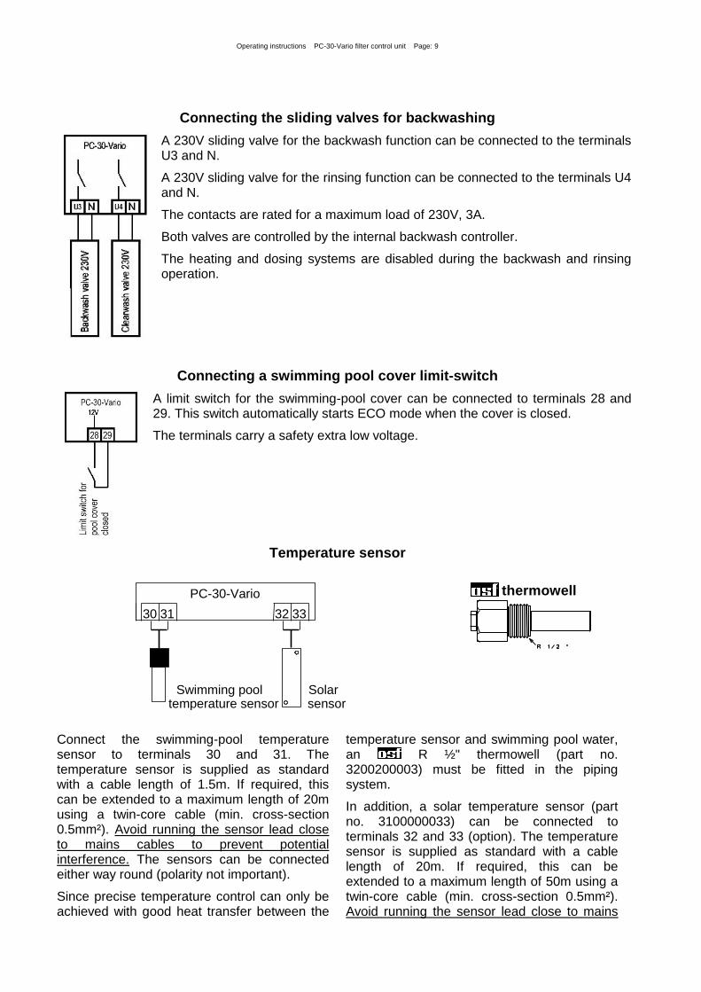
Connecting the sliding valves for backwashing
A 230V sliding valve for the backwash function can be connected to the terminals U3 and N.
A 230V sliding valve for the rinsing function can be connected to the terminals U4 and N.
The contacts are rated for a maximum load of 230V, 3A.
Both valves are controlled by the internal backwash controller.
The heating and dosing systems are disabled during the backwash and rinsing operation.
Connecting a swimming pool cover limit-switch
A limit switch for the swimming-pool cover can be connected to terminals 28 and 29. This switch automatically starts ECO mode when the cover is closed.
The terminals carry a safety extra low voltage.
Temperature sensor
temperature sensor
Swimming pool
30 31
sensor
Solar
32 33
PC-30-Vario
thermowell
Connect the swimming-pool temperature sensor to terminals 30 and 31. The temperature sensor is supplied as standard with a cable length of 1.5m. If required, this can be extended to a maximum length of 20m using a twin-core cable (min. cross-section 0.5mm²). Avoid running the sensor lead close to mains cables to prevent potential interference. The sensors can be connected either way round (polarity not important).
Since precise temperature control can only be achieved with good heat transfer between the
temperature sensor and swimming pool water, an R ½" thermowell (part no. 3200200003) must be fitted in the piping system.
In addition, a solar temperature sensor (part no. 3100000033) can be connected to terminals 32 and 33 (option). The temperature sensor is supplied as standard with a cable length of 20m. If required, this can be extended to a maximum length of 50m using a twin-core cable (min. cross-section 0.5mm²). Avoid running the sensor lead close to mains
Operating instructions PC-30-Vario filter control unit Page: 10
cables to prevent potential interference. The solar temperature sensor should be fitted at the solar collector output in good thermal
contact with the returning water flow. The temperature at the installation position for the temperature sensor must not exceed 80°C.
Frost protection
When the frost protection function is enabled, the temperature sensor connected to terminals 32 and 33 is used as the air temperature sensor for frost protection. Solar temperature control is disabled when frost protection is in use. In installations without solar heating, the frost-protection sensor should be installed in a
suitable position outdoors. Once the temperature at the temperature sensor drops below 0°C (factory setting), the filter system is activated. In this case, the temperature controller regulates the heater to a target temperature of 3°C.
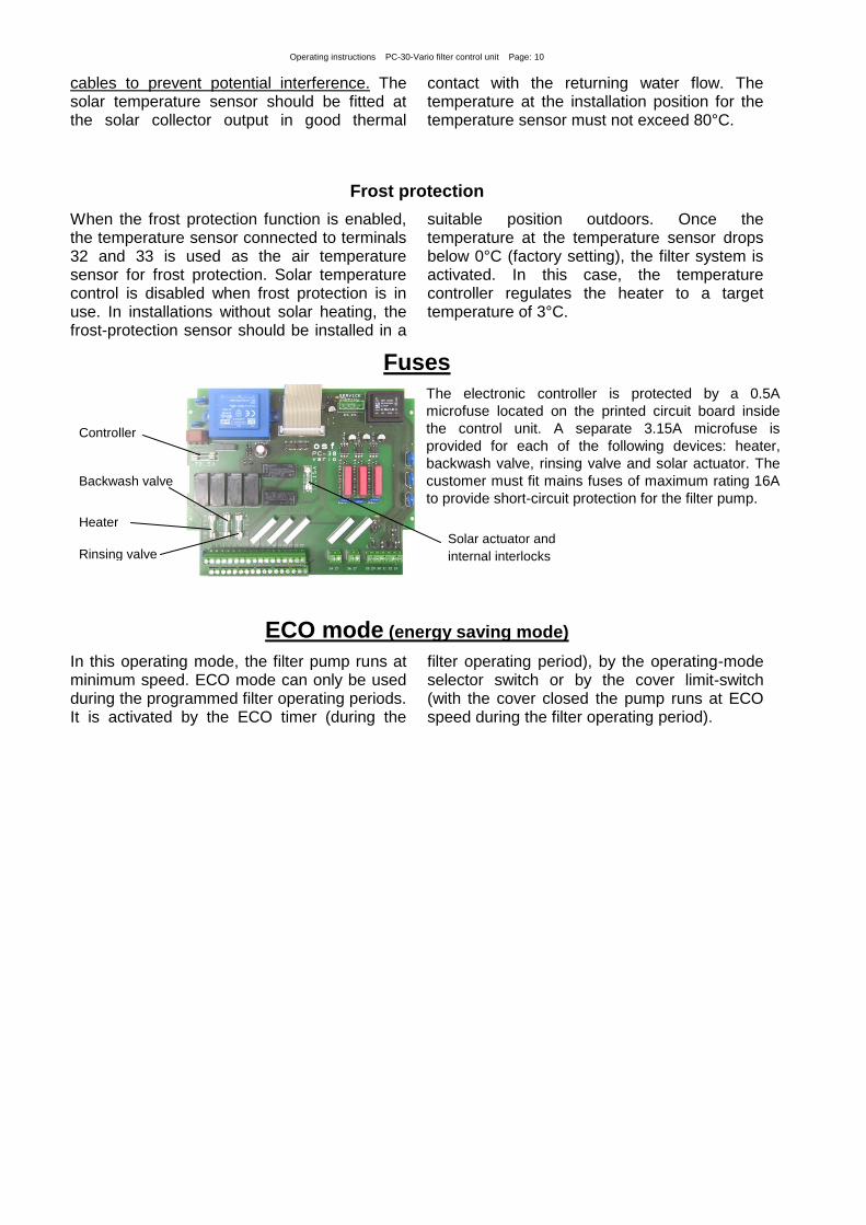
Fuses
The electronic controller is protected by a 0.5A
microfuse located on the printed circuit board inside
the control unit. A separate 3.15A microfuse is
provided for each of the following devices: heater,
backwash valve, rinsing valve and solar actuator. The
customer must fit mains fuses of maximum rating 16A
to provide short-circuit protection for the filter pump.
ECO mode (energy saving mode)
In this operating mode, the filter pump runs at minimum speed. ECO mode can only be used during the programmed filter operating periods. It is activated by the ECO timer (during the
filter operating period), by the operating-mode selector switch or by the cover limit-switch (with the cover closed the pump runs at ECO speed during the filter operating period).
Controller
Solar actuator and
internal interlocks
Heater
Backwash valve
Rinsing valve

Operating instructions for PC-30-Vario filter control unit Page: 11 (26)
Controls on the front panel
LCD display
23.4
Fr 14:46
°C
Standard operating display showing current time and water temperature.
level control
The filter pump has been switched on by the NR-12-TRS-2 water level controller.
6-way backwash
The filter pump has been switched on by the EUROTRONIK-10 backwash controller. (Heater is disabled.)
Pump locked
The filter pump has been switched off by the EUROTRONIK-10 controller or the NR-12-TRS-2 water level controller.
Back- washing
The filter pump is on because backwashing is in progress using the connected sliding valve. (Heater is disabled.)
Clear- washing
The filter pump is on because rinsing is in progress using the connected sliding valve. (Heater is disabled.)
pump
locked
The filter pump is off because the winding protection switch has tripped.
Fr 14:46 -----°
The temperature sensor for the water temperature appears to be faulty.
Operating mode selection
Press the button (several times if necessary) to select the operating mode.
Off/0 The control unit is off.
Caution! This does not disconnect the control unit from the power supply
Solar heater ON/OFF
Solar heater indicator light
Solar indicator light
Heater ON/OFF
Indicator light for backwash
using sliding valve
Backwash programming
"Decrease value" button
"Increase value" button
Temperature adjustment
Timer programming
Filter pump
indicator lights
ECO mode programming
Operating mode
indicator lights
Time setting
Operating mode
selection

Operating instructions PC-30-Vario filter control unit Page: 12
Automatic The filter system is switched on and off by the timer.
Eco When the timer is on, the filter pump runs at low speed.
Manual The filter system is running continuously.
Pump indicator light
These indicator lights indicate which mode the filter pump is running in.
Pump is disabled. It may have been switched off by the winding protection switch, by the water level controller or by the EUROTRONIK-10 controller.
All lights OFF: the filter pump is off.
BOTTOM light ON: the filter pump is running in ECO mode.
BOTTOM and CENTRE light ON: the filter pump is running at normal speed.
All 3 lights ON: the pump is running at maximum speed.
Heater indicator light
Heater switch
This indicator light shows the heater operating mode. The colour of the light indicates the heater operating mode:
off: the heater is off.
green: the heater is running.
red: the heater is disabled. You can use the button to switch the heater on or off.
Solar heater indicator light
Solar heater switch
If a solar sensor is connected to the controller, this indicator light shows the current operating state of the solar heater.
off: the solar heater is off (temperature controller).
green: the solar heater is running.
red: the solar heater is off (switch). You can use the button to switch the solar heater on or off.
Backwash using sliding valve
This indicator light shows whether a backwash operation using sliding valves is currently in progress.
Temperature selection
Use the button to select the water temperature for the swimming pool:
1. Press the button the display shows
24.5
water: °C
2. You can now use the and buttons to set the temperature you require in a range of 0°C to 40°C.
3. To save the required temperature, press the button again. If no button is

Operating instructions PC-30-Vario filter control unit Page: 13
pressed during an interval of more than 10 seconds when setting the temperature, the last temperature selected is saved automatically and the standard operating display reappears.
ECO temperature selection
Use the button to select the reduction in temperature for ECO mode:
1. Press the button twice the display shows
3.0
ECO descent
°C (scrolling text)
2. You can now use the and buttons to set the temperature reduction you require in a range of 0°C to 15°C.
3. To save the required temperature, press the button again. If no button is pressed during an interval of more than 10 seconds when setting the temperature, the last temperature selected is saved automatically and the standard operating display reappears.
Time setting
Use the button to set the current time:
1. Press the button the display shows
Sa 14:46 Time
and the minute display flashes.
2. You can now use the and buttons to set the minutes.
3. Press the button the hour display flashes.
4. You can now use the and buttons to set the hour.
5. Press the button the day of the week flashes.
6. You can now use the and buttons to set the day of the week.
To save the set time, press the button again. If no button is pressed during an interval of more than 10 seconds when setting the time, the last time displayed is saved automatically and the standard operating display reappears.
Timer programming
Use the button to program the built-in timer. Note that the switch-on time and the associated switch-off time must always be entered as a pair:
1. Press the button the display shows -----1.
if a switching time has not been programmed yet.
2. After pressing either button or , or if a switching time has been pre-
programmed, the display shows
0:00
0:00
1.
and the minutes in the top time display flash (switch-on time).
Note: you can press the button to adopt the current time.
3. You can now use the and buttons to set the minutes for the switch-on time you require.
4. Press the button again the hour for the switch-on time flashes
5. You can now use the and buttons to set the hour for the switch-on time you require.
6. Press the button again the minutes for the switch-off time flash
7. You can now use the and buttons to set the minutes for the switch-off time you require. Note: you can press the button to adopt the current time;
Operating instructions PC-30-Vario filter control unit Page: 14
pressing both and buttons at once adopts the previously set switch-on time.
8. Press the button again the hour for the switch-off time flashes
9. You can now use the and buttons to set the hour for the switch-off time you require.
10. Repeat steps 1-9 if you wish to program further switching times.
11. To save the switching times, press the button again. If no button is pressed during an interval of more than 10 seconds when setting the time, the last switching time displayed is saved automatically and the standard operating display reappears.
If switching times have been pre-programmed, they can be deleted using the button:
1. Press the button repeatedly until the switching time you wish to delete
appears in the display and the switch-on time is flashing
10:00
16:00
3.
. 2. Press both and buttons at once to delete the switching time.
ECO-timer programming
Use the button to program the built-in timer. Note that the switch-on time and the associated switch-off time must always be entered as a pair:
1. Press the button the display shows -----1.
if a switching time has not been programmed yet.
2. After pressing either button or , or if a switching time has already been
programmed, the display shows
0:00
0:00
1.
and the minutes in the top time display flash (switch-on time).
Note: you can press the button to adopt the current time.
3. You can now use the and buttons to set the minutes for the switch-on time you require.
4. Press the button again the hour for the switch-on time flashes
5. You can now use the and buttons to set the hour for the switch-on time you require.
6. Press the button again the minutes for the switch-off time flash
7. You can now use the and buttons to set the minutes for the switch-off time you require. Note: you can press the button to adopt the current time; pressing both and buttons at once adopts the previously set switch-on time.
8. Press the button again the hour for the switch-off time flashes
9. You can now use the and buttons to set the hour for the switch-off time you require.
10. Repeat steps 1-9 if you wish to program further switching times.
11. To save the switching times, press the button again. If no button is pressed during an interval of more than 10 seconds when setting the time, the last switching time displayed is saved automatically and the standard operating display reappears.
If switching times have been pre-programmed, they can be deleted using the button:
Operating instructions PC-30-Vario filter control unit Page: 15
1. Press the button repeatedly until the switching time you wish to delete
appears in the display and the switch-on time is flashing
10:00
16:00
3.
. 2. Press both and buttons at once to delete the switching time.
Backwash programming
Use the button to program backwashing using sliding valves.
1. After pressing the button once, you can use the and buttons to set the
length of the backwash operation
10 sec. backwash .
2. After pressing the button again, you can use the and buttons to set the
length of the rinsing operation
10 sec.
clearwas .
3. After pressing the button again, you can use the and buttons and the
button to set the start time for the combined backwash/rinse cycle
Mo 16:00
1. Start . Note: you can press the button to adopt the current time; pressing both and buttons at once deletes the cycle start time.
Pressing and holding the button for longer than 5 seconds will launch a backwash/rinse cycle.
Changing the language
Press the button several times until the display shows
English
Language
1. You can now use the and buttons to set the language.
2. To save the language you require, press the button again.
Enabling frost protection mode
23.4 Fr 14:46
°C *
Press the button several times until the display shows
OFF
Frost
1. You can now use the and buttons to enable/disable frost protection mode.
2. To save the operating mode you require, press the button again. When frost protection mode is on, a snowflake icon appears in the display.
INFO button
After pressing the INFO button, the display first shows the solar sensor temperature (if a solar sensor is connected):
37.6°C
Air
Pressing the INFO button successively will retrieve the following information:

Operating instructions PC-30-Vario filter control unit Page: 16
1. Solar temperature
2. Language setting (you can switch language by pressing the or button)
3. Frost protection (you can enable/disable frost protection by pressing the or button)
4. Filter pump operating-hours counter
5. ECO operating-hours counter
6. Heater operating-hours counter
7. Solar heater operating-hours counter
8. Software version
9. Sensor calibration
Service Terminal
An osf Service Terminal (part no. 3010000900) can be connected to the control unit. This terminal can be used to set the optimum control unit configuration for a particular swimming pool installation, for commissioning the control unit and for fault diagnosis. The connector for the Service Terminal is located on the printed circuit
board inside the control unit. Always disconnect the control unit
from the power supply before opening the case and plugging
in the Service Terminal. After switching on the control unit, the display on the Service Terminal shows the first 4 lines of the diagnostic text, e.g.:
Filtersystem off
Temp. reached
Water: 23.0°
Solar: 38.4°
Filter system operating mode
Heater operating mode
measured water temperature
measured collector temperature
Use the and buttons on the terminal to display other lines. If required, you can make
changes to the values in the top line after pressing the button on the terminal.
Filter system operating mode
This line shows the current operating mode of the filter system.
The following texts may be displayed:
Control unit off The control unit has been switched off using the button.
Filter system off The filter system is off.
Filter running The filter system has been switched on by the timer or the button on the front panel.
Run-on time The filter pump is still running after switching off the heater.
Forced switch-on The filter pump has been switched on by the EUROTRONIK-10 backwash controller or the NR-12-TRS-2 water level controller.
Priority mode The temperature controller has switched on the filter pump outside the set filter operating times because the temperature controller is operating in priority mode.
Pump disabled The filter pump has been temporarily switched off by the EUROTRONIK-10 controller or the NR-12-TRS-2 water level controller.
Connector
Operating instructions PC-30-Vario filter control unit Page: 17
Backwashing The filter pump is on because backwashing is in progress using the sliding valve.
Rinsing The filter pump is on because rinsing is in progress using the sliding valve.
Frost protection mode The filter pump is operating in frost protection mode.
Heater operating mode
This line shows the current operating mode of the temperature controller.
Controller off The heater has been switched off using the button.
Aux. heating off The heater is off outside the filter operating times.
Heater disabled The heater is off because the EUROTRONIK-10 controller has caused a forced switch-on.
Temp. reached The heater is off because the set target temperature has been reached.
Aux. heating on The heater is on because the water temperature is below the set target temperature.
Solar heater on The solar heater is on because the water temperature is below the set target temperature and the collector is warmer than the swimming-pool water.
Frost risk The heater is on in frost protection mode.
Temperature at the solar sensor
Display text: Solar:
Temperature at the water sensor
Display text: Water:
Set water temperature (target temperature) Display text: Set temp.
This line displays the target temperature that was set using the button on the front panel.
Temperature reduction in Eco mode
Display text: Eco temp. drop
This line displays the reduction in temperature for ECO mode that was set using the button on the front panel.
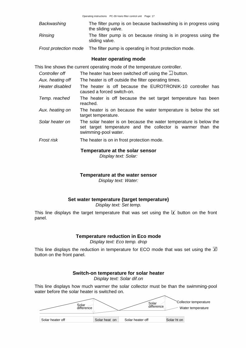
Switch-on temperature for solar heater Display text: Solar dif.on
This line displays how much warmer the solar collector must be than the swimming-pool water before the solar heater is switched on.
Solar
difference
Collector temperature
Water temperature
Solar heater off Solar heat on Solar heater off Solar ht on
Solar
difference
Operating instructions PC-30-Vario filter control unit Page: 18
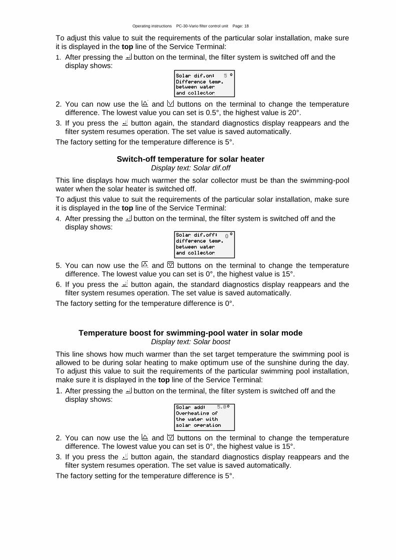
To adjust this value to suit the requirements of the particular solar installation, make sure
it is displayed in the top line of the Service Terminal:
1. After pressing the button on the terminal, the filter system is switched off and the display shows:
Solar dif.on: °
Difference temp.
between water
and collector
5
2. You can now use the and buttons on the terminal to change the temperature difference. The lowest value you can set is 0.5°, the highest value is 20°.
3. If you press the button again, the standard diagnostics display reappears and the filter system resumes operation. The set value is saved automatically.
The factory setting for the temperature difference is 5°.
Switch-off temperature for solar heater Display text: Solar dif.off
This line displays how much warmer the solar collector must be than the swimming-pool water when the solar heater is switched off.
To adjust this value to suit the requirements of the particular solar installation, make sure
it is displayed in the top line of the Service Terminal:
4. After pressing the button on the terminal, the filter system is switched off and the display shows:
Solar dif.off: °
difference temp.
between water
and collector
0
5. You can now use the and buttons on the terminal to change the temperature difference. The lowest value you can set is 0°, the highest value is 15°.
6. If you press the button again, the standard diagnostics display reappears and the filter system resumes operation. The set value is saved automatically.
The factory setting for the temperature difference is 0°.
Temperature boost for swimming-pool water in solar mode Display text: Solar boost
This line shows how much warmer than the set target temperature the swimming pool is allowed to be during solar heating to make optimum use of the sunshine during the day. To adjust this value to suit the requirements of the particular swimming pool installation,
make sure it is displayed in the top line of the Service Terminal:
1. After pressing the button on the terminal, the filter system is switched off and the display shows:
Solar add: °
Overheating of
the water with
solar operation
5.0
2. You can now use the and buttons on the terminal to change the temperature
difference. The lowest value you can set is 0°, the highest value is 15°.
3. If you press the button again, the standard diagnostics display reappears and the filter system resumes operation. The set value is saved automatically.
The factory setting for the temperature difference is 5°.

Operating instructions PC-30-Vario filter control unit Page: 19
Maximum temperature Display text: limit temp.
This line displays the maximum temperature at which the solar heater is switched off automatically for safety reasons irrespective of the set target value. To adjust this value to suit the requirements of the particular swimming pool installation, make sure it is displayed
in the top line of the Service Terminal:
1. After pressing the button on the terminal, the filter system is switched off and the display shows:
Temp limit: °
Maximum possible
water temp. with
solar operation
40.0
2. You can now use the and buttons on the terminal to change the temperature limit.
The lowest value you can set is 30°, the highest value is 50°.
3. If you press the button again, the standard diagnostics display reappears and the filter system resumes operation. The set value is saved automatically.
The factory setting for the maximum temperature is 40°. This temperature limit only affects the solar heater.
Heater hysteresis Display text: Min. heating:
This line shows the minimum length of time that the heater remains on or off under temperature control to avoid excessively short switching intervals. To adjust this value to
suit the requirements of the particular heating system, make sure it is displayed in the top line:
1. After pressing the button on the terminal, the filter system is switched off and the display shows:
Min. heating:
s Min. switching
time of the
heater
120
2. You can now use the and buttons on the terminal to change the minimum time in
10 second increments. The smallest value you can set is 10s, the largest value is 1800s.
3. If you press the button again, the standard diagnostics display reappears and the filter system resumes operation. The set value is saved automatically.
The time set here only affects the behaviour of the temperature controller. The auxiliary heating is switched off immediately, regardless of the set delay, when the filter pump is switched off. The factory setting for the minimum time is 2 minutes.
Solar heater hysteresis Display text: Min. solar:
This line shows the minimum length of time that the solar heater remains on or off under temperature control to avoid excessively short switching intervals. To adjust this value to suit the requirements of the particular solar installation, make sure it is displayed in the
top line:
1. After pressing the button on the terminal, the filter system is switched off and the display shows:
Min. solar: s
Min. switching
time of the
Solar heating
120
2. You can now use the and buttons on the terminal to change the minimum time in
10 second increments. The smallest value you can set is 10s, the largest value is 1800s.

Operating instructions PC-30-Vario filter control unit Page: 20
3. If you press the button again, the standard diagnostics display reappears and the filter system resumes operation. The set value is saved automatically.
The time set here only affects the behaviour of the temperature controller. The heater is switched off immediately, regardless of the set delay, when the filter pump is switched off. The factory setting for the minimum time is 2 minutes.
Filter pump run-on after timed switch-off Display text: subs. time:
This line displays how long the filter pump continues to run after the heater is switched off. To adjust this value to suit the requirements of the particular filter system, make sure it is
displayed in the top line:
1. After pressing the button on the terminal, the filter system is switched off and the display shows:
Subs. time: s
subsequent
running time of
the filter pump
0
2. You can now use the and buttons on the terminal to change the run-on time. The
smallest value you can set is 0s, the largest value is 1800s.
3. If you press the button again, the standard diagnostics display reappears and the filter system resumes operation. The set value is saved automatically.
The filter pump run-on is factory-set to off (run-on time = 0).
Priority of temperature controller over timer Display text: Heat. priori.
This line displays whether the temperature controller has priority over the settings for the filter operating times. In priority mode, the filter pump can be switched on by the temperature controller even outside the set filter operating times. Without priority, temperature control only operates during the filter operating times.
The following texts may be displayed:
Priority OFF Auxiliary heating only operates during the filter operating times.
Priority ON Temperature control also operates outside the filter operating times. If the water temperature drops below the set target temperature, the filter pump and auxiliary heating are switched on automatically
To enable/disable priority mode, make sure it is displayed in the top line of the Service Terminal:
1. After pressing the button on the terminal, the filter system is switched off and the display shows:
Heat. priori: OFF
Priority circuit
of caloric
heater
2. You can now use the button on the terminal to enable priority mode, and the
button to disable it again.
3. If you press the button again, the standard diagnostics display reappears and the filter system resumes operation.
The priority mode for auxiliary heating is factory-set to off.
Operating instructions PC-30-Vario filter control unit Page: 21
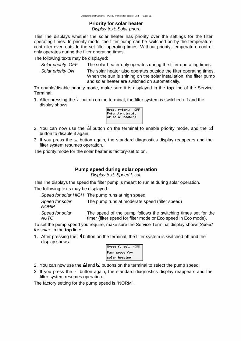
Priority for solar heater Display text: Solar priori.
This line displays whether the solar heater has priority over the settings for the filter operating times. In priority mode, the filter pump can be switched on by the temperature controller even outside the set filter operating times. Without priority, temperature control only operates during the filter operating times.
The following texts may be displayed:
Solar priority OFF The solar heater only operates during the filter operating times.
Solar priority ON The solar heater also operates outside the filter operating times. When the sun is shining on the solar installation, the filter pump and solar heater are switched on automatically.
To enable/disable priority mode, make sure it is displayed in the top line of the Service Terminal:
1. After pressing the button on the terminal, the filter system is switched off and the display shows:
Heat. priori: OFF
Priority circuit
of solar heating
2. You can now use the button on the terminal to enable priority mode, and the
button to disable it again.
3. If you press the button again, the standard diagnostics display reappears and the filter system resumes operation.
The priority mode for the solar heater is factory-set to on.
Pump speed during solar operation Display text: Speed f. sol.
This line displays the speed the filter pump is meant to run at during solar operation.
The following texts may be displayed:
Speed for solar HIGH The pump runs at high speed.
Speed for solar NORM
The pump runs at moderate speed (filter speed)
Speed for solar AUTO
The speed of the pump follows the switching times set for the timer (filter speed for filter mode or Eco speed in Eco mode).
To set the pump speed you require, make sure the Service Terminal display shows Speed
for solar: in the top line:
1. After pressing the button on the terminal, the filter system is switched off and the display shows:
Speed f. sol. NORM
Pump speed for
solar heating
2. You can now use the and buttons on the terminal to select the pump speed.
3. If you press the button again, the standard diagnostics display reappears and the filter system resumes operation.
The factory setting for the pump speed is "NORM".
Operating instructions PC-30-Vario filter control unit Page: 22
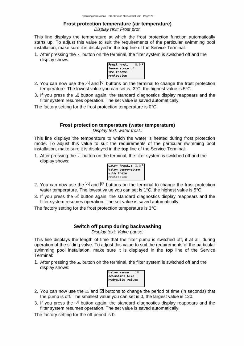
Frost protection temperature (air temperature) Display text: Frost prot.
This line displays the temperature at which the frost protection function automatically starts up. To adjust this value to suit the requirements of the particular swimming pool
installation, make sure it is displayed in the top line of the Service Terminal:
1. After pressing the button on the terminal, the filter system is switched off and the display shows:
Frost prot. °
Temperature of
the freeze
protection
0.0
2. You can now use the and buttons on the terminal to change the frost protection
temperature. The lowest value you can set is -3°C, the highest value is 5°C.
3. If you press the button again, the standard diagnostics display reappears and the filter system resumes operation. The set value is saved automatically.
The factory setting for the frost protection temperature is 0°C.
Frost protection temperature (water temperature) Display text: water frost.:
This line displays the temperature to which the water is heated during frost protection mode. To adjust this value to suit the requirements of the particular swimming pool
installation, make sure it is displayed in the top line of the Service Terminal:
1. After pressing the button on the terminal, the filter system is switched off and the display shows:
water frost.: °
Water temperature
with freze
protection
3.0
2. You can now use the and buttons on the terminal to change the frost protection
water temperature. The lowest value you can set is 1°C, the highest value is 5°C.
3. If you press the button again, the standard diagnostics display reappears and the filter system resumes operation. The set value is saved automatically.
The factory setting for the frost protection temperature is 3°C.
Switch off pump during backwashing Display text: Valve pause:
This line displays the length of time that the filter pump is switched off, if at all, during operation of the sliding valve. To adjust this value to suit the requirements of the particular
swimming pool installation, make sure it is displayed in the top line of the Service Terminal:
1. After pressing the button on the terminal, the filter system is switched off and the display shows:
Valve pause
actuating time
hydraulic valves
10
2. You can now use the and buttons to change the period of time (in seconds) that
the pump is off. The smallest value you can set is 0, the largest value is 120.
3. If you press the button again, the standard diagnostics display reappears and the filter system resumes operation. The set value is saved automatically.
The factory setting for the off period is 0.
Operating instructions PC-30-Vario filter control unit Page: 23
Pump operating time
Display text: Pump time:
This line shows the total number of operating hours for the filter pump.
ECO operating time
Display text: Eco time:
This line shows the total number of operating hours for Eco mode.
Heater operating time
Display text: Heat. time:
This line shows the total number of operating hours for the heater.
Solar operating time
Display text: Solar time:
This line shows the total number of operating hours for the solar heater.
Backwash counter (internal)
Display text: In.backwash:
This line displays how often a backwash operation using sliding valves has been launched.
Backwash counter (external)
Display text: Ex.backwash:
This line displays how often a backwash operation has been started by the EUROTRONIK-10 controller.
The following display lines help the Service Engineer to check the input signals and output relays of the filter control unit.
Forced switch-on of the NR-12-TRS-2
Display text: Forced start:
This line displays whether the NR-12-TRS-2 water level controller has requested a forced switch-on.
The following texts may be displayed:
Forced switch-on OFF No forced switch-on or terminals 11 and 12 not connected
Forced switch-on ON Forced switch-on requested or terminals 11 and 12 connected

Operating instructions PC-30-Vario filter control unit Page: 24
EUROTRONIK-10
This line displays whether the EUROTRONIK-10 controller is switching on the filter pump during backwashing or rinsing.
The following texts may be displayed:
EUROTRONIK OFF No switch-on command from the EUROTRONIK-10
EUROTRONIK ON The EUROTRONIK-10 has switched on the filter pump
locking
This line displays whether the filter system has been disabled by the EUROTRONIK-10, the NR-12-TRS-2 or the winding protection switch.
The following texts may be displayed:
locking OFF The pump is off (one of the contacts is open).
locking ON Pump operation is enabled (all interlock contacts are closed)
The following lines are used for manual control of the output relays.
Filter pump
When the operating status of the filter pump is displayed in the top line of the Service Terminal, you can enable/disable the pump manually:
1. After pressing the button on the terminal, the filter system is switched off and the display shows:
Filter pump: OFF
Pump can be
operated
manually
2. You can now use the and buttons on the terminal to switch the filter pump into the following operating modes: ON, OFF, ECO, MAX
3. If you press the button again, the standard diagnostics display reappears and the filter system resumes operation.
Solar system
When the operating status of the solar heater is displayed in the top line of the Service Terminal, you can enable/disable the solar heater manually:
1. After pressing the button on the terminal, the filter system is switched off and the display shows:
Solar system
MANUAL OPERATION
Actuator: OFF
Pump: OFF
2. You can now use the button on the terminal to switch on the solar heater, and the button to switch it off again. After switching on the solar heater, the display shows:
Solar system
MANUAL OPERATION
Actuator: ON
Pump: OFF
3. You can now use the button to switch on the filter pump as well. After switching on the filter pump, the display shows:
Solar system
MANUAL OPERATION
Actuator: ON
Pump: ON
Operating instructions PC-30-Vario filter control unit Page: 25
4. If you press the button again, the standard diagnostics display reappears and the filter system resumes operation.
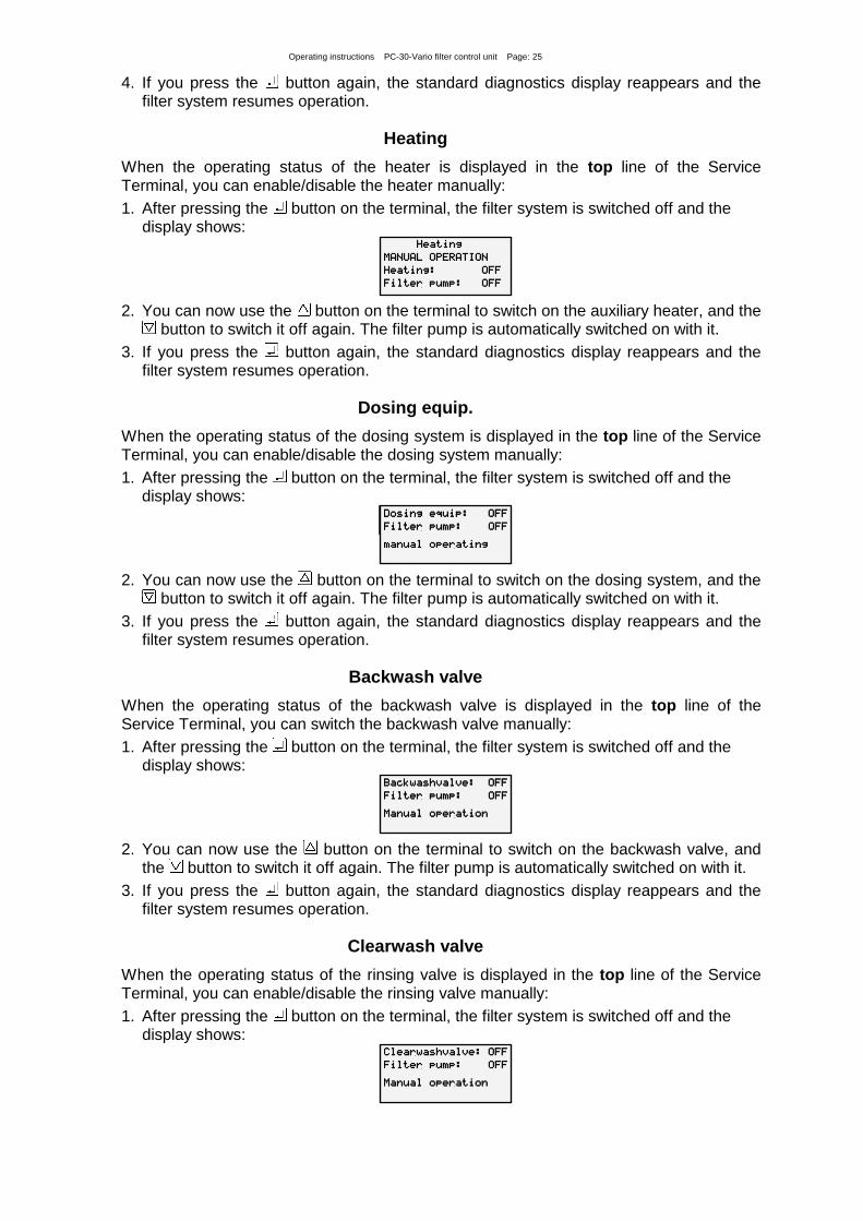
Heating
When the operating status of the heater is displayed in the top line of the Service Terminal, you can enable/disable the heater manually:
1. After pressing the button on the terminal, the filter system is switched off and the display shows:
Heating
MANUAL OPERATION
Heating: OFF
Filter pump: OFF
2. You can now use the button on the terminal to switch on the auxiliary heater, and the button to switch it off again. The filter pump is automatically switched on with it.
3. If you press the button again, the standard diagnostics display reappears and the filter system resumes operation.
Dosing equip.
When the operating status of the dosing system is displayed in the top line of the Service Terminal, you can enable/disable the dosing system manually:
1. After pressing the button on the terminal, the filter system is switched off and the display shows:
Solar system
MANUAL OPERATION
Actuator: ON
Pump: OFF
Dosing equip: OFF
Filter pump: OFF
manual operating
2. You can now use the button on the terminal to switch on the dosing system, and the button to switch it off again. The filter pump is automatically switched on with it.
3. If you press the button again, the standard diagnostics display reappears and the filter system resumes operation.
Backwash valve
When the operating status of the backwash valve is displayed in the top line of the Service Terminal, you can switch the backwash valve manually:
1. After pressing the button on the terminal, the filter system is switched off and the display shows:
Backwashvalve: OFF
Filter pump: OFF
Manual operation
2. You can now use the button on the terminal to switch on the backwash valve, and the button to switch it off again. The filter pump is automatically switched on with it.
3. If you press the button again, the standard diagnostics display reappears and the filter system resumes operation.
Clearwash valve
When the operating status of the rinsing valve is displayed in the top line of the Service Terminal, you can enable/disable the rinsing valve manually:
1. After pressing the button on the terminal, the filter system is switched off and the display shows:
Clearwashvalve: OFF
Filter pump: OFF
Manual operation

Operating instructions PC-30-Vario filter control unit Page: 26
2. You can now use the button on the terminal to switch on the rinsing valve, and the button to switch it off again. The filter pump is automatically switched on with it.
3. If you press the button again, the standard diagnostics display reappears and the filter system resumes operation.
Language
When Language is displayed in the top line of the Service Terminal, you can toggle the language setting:
1. After pressing the button, the display shows the following text:
Language
selection
Deutsch English
2. You can now use the and buttons on the terminal to select the language.
3. If you press the button again, the standard diagnostics display reappears.
Calibrating the temperature control system (sensor calibration)
The electronic temperature controller and the temperature sensors have been calibrated in the factory to work correctly together. If one of the sensors is replaced or a sensor lead is lengthened, the system may need to be recalibrated using the Info button on the control unit. Since the solar temperature controller only works properly when the sensors are calibrated accurately, this calibration should be performed solely by a trained Service Engineer.
Wiring diagram
Relax and enjoy your swimming pool!
Hansjürgen Meier
Elektrotechnik und Elektronik GmbH & Co KG
Eichendorffstraße 6
D-32339 Espelkamp
Email: [email protected]
Internet: www.osf.de
Subject to changes June 2018
Sensor
water
temp.
Sensor
solar
temp.
* Remove link if NR-12-TRS-2 and/or
EUROTRONIK-10 connected
L
N
U1 U2 U3 U4 U5 U6 2 3 4 5 WSK 11 12 13 14 15 16 17 18 19 20 21 22 23 24 25 26 27 28 29 30 31 32 33
N
Hea
ter
230V
max
.3A
Win
ding
pr
otec
tion
switc
h
clos
e
d op
en
N N N N
Solar
actuator
Cle
arw
ash
valv
e 23
0V
Bac
kwas
h va
lve
230V
Mai
ns 2
30V
50H
z
Eurotronik-10
NR-12-TRS-2
NR-12-
TRS-2
* *
M~
230V
EC
O s
peed
Bac
kwas
h sp
eed
Pum
p st
op
Dosin
g s
yste
m
flo
atin
g c
onta
ct
Heate
r
flo
atin
g c
onta
ct
Lim
it s
witch
for
pool cover
clo
sed
12V~
PC-30-Vario