filleting sharp edges of multi-partitioned volume finite
TRANSCRIPT

HAL Id: hal-01118671https://hal.archives-ouvertes.fr/hal-01118671
Submitted on 1 Apr 2015
HAL is a multi-disciplinary open accessarchive for the deposit and dissemination of sci-entific research documents, whether they are pub-lished or not. The documents may come fromteaching and research institutions in France orabroad, or from public or private research centers.
L’archive ouverte pluridisciplinaire HAL, estdestinée au dépôt et à la diffusion de documentsscientifiques de niveau recherche, publiés ou non,émanant des établissements d’enseignement et derecherche français ou étrangers, des laboratoirespublics ou privés.
Filleting sharp edges of multi-partitioned volume finiteelement meshes
Ruding Lou, Jean-Philippe Pernot, Franca Giannnini, Philippe Veron, BiancaFalcidieno
To cite this version:Ruding Lou, Jean-Philippe Pernot, Franca Giannnini, Philippe Veron, Bianca Falcidieno. Filletingsharp edges of multi-partitioned volume finite element meshes. Engineering Computations, 2015, 32(1), pp.129-154. �10.1108/EC-03-2013-0074�. �hal-01118671�

Filleting sharp edges ofmulti-partitioned volumefinite element meshes
Ruding LouInstitut Image – Le2i UMR CNRS 6306, Arts et Metiers ParisTech,
Chalon-sur-Saone, FranceJean-Philippe Pernot
CNRS-LSIS, Arts et Metiers ParisTech, Aix-en-Provence, FranceFranca Giannini
IMATI-CNR, Consiglio Nazionale delle Ricerche, Genoa, ItalyPhilippe Veron
CNRS-LSIS, Arts et Metiers ParisTech, Aix-en-Provence, France, andBianca Falcidieno
IMATI-CNR, Consiglio Nazionale delle Ricerche, Genoa, Italy
AbstractPurpose – The purpose of this paper is to set up a new framework to enable direct modifications ofvolume meshes enriched with semantic information associated to multiple partitions. An instance offilleting operator is prototyped under this framework and presented in the paper.Design/methodology/approach – In this paper, a generic mesh modification operator has beendesigned and a new instance of this operator for filleting finite element (FE) sharp edges of tetrahedralmulti-partitioned meshes is also pro-posed. The filleting operator works in two main steps. The outerskin of the tetrahedral mesh is first deformed to round user-specified sharp edges while satisfyingconstraints relative to the shape of the so-called Virtual Group Boundaries. Then, in the filleting area,the positions of the inner nodes are relaxed to improve the aspect ratio of the mesh elements.Findings – The classical mainstream methodology for product behaviour optimization involves therepetition of four steps: CAD modelling, meshing of CAD models, enrichment of models with FEsimulation semantics and FEA. This paper highlights how this methodology could be simplified bytwo steps: simulation model modification and FEA. The authors set up a new framework to enabledirect modifications of volume meshes enriched with semantic information associated to multiplepartitions and the corresponding fillet operator is devised.Research limitations/implications – The proposed framework shows only a paradigm of directmodifications of semantic enriched meshes. It could be further more improved by adding or changingthe modules inside. The fillet operator does not take into account the exact radius imposed by user.With this proposed fillet operator the mesh element density may not be enough high to obtain wishedsmoothness.Originality/value – This paper fulfils an identified industry need to speed up the product behaviouranalysis process by directly modifying the simulation semantic enriched meshes.Keywords Computer aided design, FE analysis, Fillet, Finite element mesh, Sharp edge,Tetrahedral mesh
NomenclatureCAD: Computer Aided DesignFEA: Finite Element Analysis
BC: Boundary ConditionVGB: Virtual Group Boundary

1. IntroductionComputer-aided tools provide important improvements both in cost and performance inall the product life cycle activities, from design to manufacturing, distribution, disposaland maintenance. In the last decades they have been collected in the so-called PLMsystems which additionally provide suitable means for the organization and archival ofthe produced data. Among them, Finite Element Analysis (FEA) plays a key role forevaluating design solutions in the context of product design and maintenance. Actually,FEA helps reducing costs while minimising the number of physical prototypes andshortening the time to market in case of new products. Actually, it reduces many costsdue to the experimental validation steps of a newly designed solution. The virtualprototyping enables the assessment of various optimized solutions and reducestime-consuming and expensive physical prototyping. Therefore the process is improvednot only by reducing the cost but also allowing the evaluation of more alternativesand consequently the achievement of better quality products and solutions. All theseadvantages are very valuable for competitive engineering and efficient industrialmaintenance studies. Since FEA represents a key element for industrial companies usingnumerical studies, improving the FEAworkflow is crucial to further reduce time and costwhile preserving the quality of numerical studies.
Classically, the mainstream methodology for product behaviour analysis involves therepetition of four steps: CAD modelling, meshing of CAD models, enrichment of modelswith finite element (FE) simulation semantics, and the FE analysis. The specification ofsimulation semantics often consists in defining the material behaviour law, the boundaryconditions (BCs) in terms of loads, fixations, etc. Figure 1(a)-(d) show an example of thisprocess illustrating these four steps for the design of a hook. The simulation semanticsdefined on the FE model of the hook are: steel material, fixation of the upper part andloading (Figure 1(c)). On this example, the FEA result indicates a stress concentration onthe designed structure. Figure 1(e) presents the zoom of the initially designed CAD model,and the corresponding FEA result is shown in Figure 1(f ). As usual, the stress
CAD(a) (b)
(c)(d)
(e) (f)
(g) (h)
MESH Sharp edges
CAD FEA
Filleting
Stress concentration
FEA SEMANTICS
load
fix
Note: Sharp edges induce a stress concentration (e), (f) that is decreased when filleting theedges (g), (h)
Figure 1.Example of a hookdesign using theclassical CAEloop (a-d)

concentrates around the sharp edges of the structure near the BC application zone. In thecase of this specific hook, the local stress constraints can reach 153 MPa. To avoid thisstress concentration problem, a solution consists in filleting the corresponding sharpedges. Therefore, the CADmodel is locally modified (Figure 1(g)), the FEmesh is recreatedand all the BCs are redefined. The new FEA result (Figure 1(h)) shows a reduction of thestress in the problematic area around 20 per cent for a given mesh finesse.
Even if such a modification process has now become very common for optimizingthe shape of products, it still suffers from some drawbacks. Actually, the FE modelpreparation steps (steps 1-3) as well as the simulation step (step 4) are time-consuming.This is even more true when considering that the design process normally requiresa succession of optimization loops where the identified four steps are repeated severaltimes before converging to the optimal solution. Unfortunately, even a small change inthe CAD model requires the updating of all the other steps with several repeatedactions. These aspects are addressed in Lou et al. (2010a, b)). Recently, an alternativemethod to FEA has appeared (Cottrell et al., 2009). Isogeometric Analysis allowsperforming FE simulations directly on CAD-models. This innovative product designevaluation mode would not need anymore the transfer from a geometry-oriented designmodel to a FE-based computational model. However, in industrial practises, the CADmodel is not necessarily available and it is mandatory to develop a new approach ofdoing the modifications directly on FE models without going back to the CAD models.Thanks to the last it is possible to generate and to evaluate alternative solutionsdirectly on enriched meshes.
Therefore, to reduce the time of the numerical study and to avoid going back tothe CAD models during the optimization design process, we have been working on thedefinition of a general CAD-less fast prototyping approach (Lou et al., 2010b). In thispaper, the various modules of our CAD-less approach are restructured to betterhighlight the “generic” character of the proposed CAD-less operator working directlyon enriched FE meshes. A newly developed instance of the generalized operator is alsopresented here. It concerns a filleting operator directly rounding 2D (triangular) and 3D(tetrahedral) enriched FE meshes along user-specified sharp edges. The proposedoperator is based on a local mesh deformation technique detailed in the paper.This approach can be integrated in advanced systems used within a PLM environment,where the versions of the considered alternative solutions, possibly sharing the sameset of FEA semantic information, can be stored. Our current focus is on the directmodification of the FEA model, and not on the management aspect of the exploited andobtained data resulting from the modification.
Our paper is organized as follows. Related works are analysed in Section 2, accordingto some pertinent criteria introduced in Section 2.1. The complete architecture of theCAD-less operator framework is presented (Section 3). Then, the mesh filleting operator,i.e. an instance of our generic operator, is detailed (Section 4). Finally, the application ofthe filleting operator on both triangle and tetrahedral meshes is illustrated (Section 5).At the end, the conclusion and future works are discussed.
2. State-of-the-art2.1 Hypotheses and restrictionsAs stated in the introduction, this paper neither addresses the way FE semantics (BCs,material behaviour laws, etc.) can be associated to geometric entities, nor how thosecrucial information can be updated and exchanged during the simulation modelpreparation steps. In spite of this, we assume that the semantic information has been

attached to the FE meshes through the use of multiple partitions, and we elaborate onthe way those enriched meshes can be directly shaped and filleted without going backto the CAD model. In this sense, all the discussions and references to the way such aprocess could be set up in a more interoperable manner are skipped since it wouldrequire a standalone paper to present and analyse all the existing and on-goingapproaches. In addition, we do not address the way the initial mesh is obtained andpotentially refined. Moreover, we do not address isogeometric analysis nor mesh-lessapproaches discussed in the introduction. Instead, we focus more on the geometricapproaches as well as on the way these methods can work on already existingsemantically enriched meshes
2.2 Adopted analysis criteria for the analysis of mesh operator for FE simulationClearly, to be really efficient and avoid multiple and time-consuming iterative updatesof CAD models as well as tedious re-meshing steps of potentially complex parts andproducts, such a CAD-less framework cannot only consider the geometric aspects.Also the treatment of the semantics, associated to the geometric entities throughthe use of partitions and groups, has to be considered. Actually, the link between thegeometric entities and the semantic information often results from the specificationof an intermediate layer made of groups. FE groups can contain nodes, edges, facesand 3D elements (e.g. tetrahedrons, hexahedra) as well as a mix of them. To perform anaccurate state-of-the-art survey in this domain, two categories of criteria have beenidentified and detailed hereunder. Each approach is then analysed according to thosecriteria and a symbol “+” (resp. “−”) is used when the approach meet (resp. does notmeet) a criterion.
Considering the geometric aspects of the direct mesh modification operators, fivecriteria can be used to analyse the proposed approaches:
(1) Local vs global modifications: this criterion is used to discriminate approaches thatwould modify locally the mesh from those modifying it globally. For example,a method that would re-mesh entirely the inner part of a volume mesh does notmeet this criterion (a-), whereas an approach whose modification can be restrictedto a subpart of the mesh will meet this criterion (a+). Actually, enriched FE mesheshave often been tuned and validated with respect to experimental results. It istherefore crucial to limit as much as possible the extent of the changes so that themodelling hypotheses and local adaptations remain valid.
(2) Preservation of the initial shape: even if the operator affects a subpart of the mesh(a+), it is important to do so that the type of the external skin of the mesh is notaffected and remains the same. For example, the insertion of a through hole insidea cube-like tetrahedral mesh should keep the six outer faces planar (b+) withoutintroducing any displacements of the outer triangles out of the six planes (b−).
(3) Aspect ratio of the mesh elements: this criterion is used to qualify themodifications with respect to the evolution of the aspect ratio of the meshelements in the modified area. The aspect ratio measures the deviation betweena mesh element and an ideal one having all its edges of equal length. When theaspect ratio is equal to 1, the element is considered as ideal. When the aspectratio is equal to 0, it means that the element is flat and has no volume and noarea. Thus, long, thin and skinny elements have a low aspect ratio (Ciarlet,1978). The aspect ratios of the modified elements can remain the same or can be
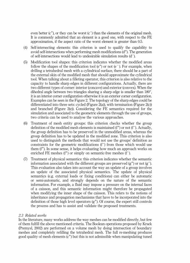
even better (c+), or they can be worst (c−) than the elements of the original mesh.It is commonly admitted that an element is a good one, with respect to the FEapproximation, if the aspect ratio of the worst element is greater than 0.5.
(4) Self-intersecting elements: this criterion is used to qualify the capability toavoid self-intersections when performing mesh modifications (d+). The generationof self-intersections would lead to undesirable simulation results (d−).
(5) Modification tool shapes: this criterion indicates whether the modified areasfollow the shapes of the modification tool (e+) or not (e�). For example, whendrilling a tetrahedral mesh with a cylindrical surface, there should be a part ofthe external skin of the modified mesh that should approximate the cylindricaltool. When talking about a filleting operator, this criterion is also relative to thecapacity to handle sharp edges in different configurations. Actually, there aretwo different types of corner: interior (concave) and exterior (convex). When thedihedral angle between two triangles sharing a sharp edge is smaller than 180°,it is an interior corner configuration otherwise it is an exterior corner configuration.Examples can be seen in the Figure 2. The topology of the sharp edges could bedifferentiated into three sets: cycled (Figure 2(a)), with termination (Figure 2(c))and branched (Figure 2(e)). Considering the FE semantics required for thesimulation and associated to the geometric elements through the use of groups,two criteria can be used to analyse the various approaches.
(6) Treatment of mesh entity groups: this criterion checks whether the groupdefinition of the modified mesh elements is maintained (f+) or not (f−). Actually,the group definition has to be preserved in the unmodified areas, whereas thegroup definition has to be updated in the modified zone. This criterion is alsoused to distinguish the methods that would not use the groups’ definition asconstraints for the geometric modifications (f−) from those which would usethem (f+). In some sense, it helps evaluating how much an approach works onenriched FE meshes (f+) or simply on semantic-free meshes (f−).
(7) Treatment of physical semantics: this criterion indicates whether the semanticinformation associated with the different groups are preserved (g+) or not (g−).This evaluation also takes into account the way an update of a group involvesan update of the associated physical semantics. The update of physicalsemantics (e.g. external loads or fixing conditions) can either be automaticor semi-automatic, and strongly depends on the nature of the semanticinformation. For example, a fluid may impose a pressure on the internal facesof a caisson, and this semantic information might therefore be propagatedwhen modifying the inner shape of the caisson. This refers to the notions ofinheritance and propagation mechanisms that have to be incorporated into thedefinition of those high level operators (g+). Of course, the expert still controlsthe process and has to assist and validate the proposed treatments.
2.3 Related worksIn the literature, many works address the way meshes can be modified directly, but fewof them fulfill the above mentioned criteria. The Boolean operations proposed by Krsek(Premysl, 2002) are performed on a volume mesh by doing intersection of boundarymeshes and completely refilling the tetrahedral mesh. The full re-meshing producesgood quality of mesh elements (c+) but this is not admissible when manipulating tuned

Cycle
(a) (b)
(c) (d)
(e) (f)
Interior corner
Interior corner
Branched node
Termination
90°
90°
Exterior corner270°
Figure 2.Examples of exteriorcorner (c) and interiorcorner (a and c).Sharp edge in a ring(a), sharp edge withterminations (c) andmultiple sharp edgebranches
FE meshes for which only local modifications are allowed (a−). Similarly, an approachto insert crack feature into a volume mesh has been designed in Bremberg and Dhondt(2008). The intersection between the crack tool surface mesh and the boundary meshof the volume mesh is computed and a complete re-meshing is performed. The qualityof the mesh elements and the shape of the modification tool are checked (c+, e+) but themodifications are not local (a−).
The Boolean operations performed on triangle meshes (Biermann et al., 2001)uses the Loop’s subdivision technique (Loop, 1987) in order to approximate theintersection. The shape of the intersection zone is not exact (e−). The intersectionrepairing in case of mesh offsetting ( Jung et al., 2004) and the mesh cutting approachproposed in Dakowicz and Gold (2005) ensure local modifications on mesh (a+)but do not satisfy the criterion relative to the quality of the mesh elements (c−).Turini et al. (2006) have proposed cutting mesh approach that directly subdivides andremoves mesh elements in contact with the tool, in order to approximate the cuttingpath Turini et al., 2006. The quality of the mesh elements is not ensured (c−) and theshape of the modification tool is not respected (e−). Chouadria et al. (2006) have proposedan approach for the treatment of digital mock-up assemblies (Chouadria and Veron,2006). The modifications are local (a+) but self-intersecting elements are not avoided(d−). The operator proposed by Chen (2007) overcomes difficulties in many degeneratedcases such as the two input models being in contact only on an edge. The conversionfrom surface model to volumetric is necessary and the quality of the produced trianglesis not addressed (c−).
Concerning the filleting of sharp edges, several approaches refer to as meshoffsetting and mesh filleting. Generally speaking, the mesh offsetting technique cannotensure local modifications (a−) and it cannot be applicable when there are interior andexterior corners on a model (e−). A surface mesh offsetting approach for scaling upthe model is presented in Kim et al. (2004). It allows producing rounded feature on aconvex sharp corner. The presented method does not take care of the quality of themesh elements (c−) and it does not avoid self-intersecting elements (d−). In addition,the offsetting is not a local modification (a−). The operator does not cover the sharpedges that are concave because after offsetting it would produce self-intersectingconfigurations. Moreover, using this approach, it is difficult to treat complex sharpedge terminations (e−), i.e. configurations where sharp edges do not form a simple loop(Figure 2(c)). The proposed mesh offset method is then extended to manufacturingoperators, e.g. material cutting (Kim and Yang, 2005). The material removing froma model is realized by offsetting the surface.
Another polygonal mesh filleting operator based on offsetting is also proposedby Chen et al. (2005). They propose two steps surface offsetting: shrinking and growing.The round transition surface is generated by growing up the shrunken mesh model.Therefore the method would change locally the fillet zone (a+). By the way, no meshelement quality optimization is performed (c−). In addition with their method it isdifficult to fillet sharp edge terminations (e−). Further offsetting (growing andshrinking) are proposed by Pavic and Kobbelt (2008) allowing to preserve thefeatures of models (b+). The uniformity of arbitrary offset distance is maintained inChen and Wang (2011).
In Hui and Lai (2006), a subdivision technique is used for smoothing a transitionzone in a blended model. For blending two meshes, the intersection mesh elementsare removed and a rough transition mesh is created to connect the two models.This created mediator mesh is subdivided until the transition from one to the

other is smooth enough. Mesh refinement plus geometric fairing algorithm isproposed in Igarashi and Hughes (2003). These techniques could be used to filleta sharp edge on a mechanical model and the modification could be constrainedin a local zone (a+). But it is anyhow difficult to cover the case of sharp edgeterminations (e−).
Surface mesh rounding/blending operations using the rolling-ball method aredefined in Lee et al. (2001), Liu et al. (2005). These methods create blending surface byusing rolling-ball method commonly applied for creating blends between two surfacesin a B-Rep model. The blending surface is then meshed and used to replace the part ofthe mesh to be rounded. The modification is local (a+) and the quality of the producedmesh is good (c+). Configurations involving creases (concave sharp edge) are handled.However, sharp edge terminations and multiple-branches sharp edges cases (Figure 2)refer to as complex configurations not fully supported (e−). In the computer graphicsand animation domains, several blending approaches have also been proposed but theydo not really meet the requirements we have in mechanical engineering ( Jin et al., 2006;Whited and Rossignac, 2009) since the mechanical fillet shape could not be ensured (e−).Finally, it is important to highlight that none of the above mentioned approaches is ableto handle the semantics attached to the mesh elements (f−, g−). Actually, they act on thegeometric models without taking care of the associated semantics. The methodsmodifying locally the mesh will preserve the group definition only in the non-modifiedarea whereas those changing completely the mesh will lose all the group definition.Table I summary all above analysis of all related works according to the declaredcriteria. Our ambition in the current paper is to design an operator having more “plus”according to each criteria. Moreover, when considering the filleting operation, one cannotice that very few methods works on tetrahedral meshes. Thus, the treatment ofenriched meshes and the treatment of tetrahedral meshes are two major contributionsof this paper.
CriteriaRef. a. b. c. d. e. f. g.
Premysl (2002) ⊖ ⊕ ⊖ ⊖ ⊖Bremberg and Dhondt (2008) ⊖ ⊕ ⊕ ⊖ ⊖Biermann et al. (2001) ⊖ ⊖ ⊖Jung et al. (2004) ⊕ ⊖ ⊖ ⊖Dakowicz and Gold (2005) ⊕ ⊖ ⊖ ⊖Turini et al. (2006) ⊖ ⊖ ⊖ ⊖Chouadria and Veron (2006) ⊕ ⊖ ⊖ ⊖Chen (2007) ⊖ ⊖ ⊖Kim et al. (2004) ⊖ ⊖ ⊖ ⊖ ⊖ ⊖Kim and Yang (2005) ⊖ ⊖ ⊖ ⊖Chen et al. (2005) ⊕ ⊖ ⊖ ⊖ ⊖Pavic and Kobbelt (2008) ⊖ ⊕ ⊖ ⊖ ⊖Chen and Wang (2011) ⊖ ⊖ ⊖ ⊖Hui and Lai (2006) ⊕ ⊖ ⊖ ⊖Igarashi and Hughes (2003) ⊕ ⊖ ⊖ ⊖Lee et al. (2001) ⊕ ⊕ ⊖ ⊖ ⊖Liu et al. (2005) ⊕ ⊕ ⊖ ⊖ ⊖Jin et al. (2006) ⊖ ⊖ ⊖Whited and Rossignac (2009) ⊖ ⊖ ⊖
Table I.Bibliographyanalysis

3. CAD-less mesh operator3.1 General structure of the operatorThe approach proposed in this paper is particularly efficient when prototyping localstructural modifications, since it avoids redoing the entire FE mesh semantic enrichment.It is not only very suitable when the original CAD model is not available, as in the case ofmaintenance, but also for the preliminary design phases where many alternative solutionsoften have to be tested. The concept of the CAD-less framework has been proposed in Louet al. (2010b) and is improved in this paper to better highlight the “generic” character of theCAD-less operators. This framework consists in a general operator structure which relieson sub-operators treating various aspects of the three levels of information (geometry andtopology of the mesh, FE mesh group and FE simulation semantics) characterising a FEAmesh model. Gathered together in this generic operator, these sub-operators performspecific changes and/or evaluations of the enriched mesh. Figure 3 illustrates the workflowof the proposed CAD-less framework working on FE mesh models.
3.2 Details of the operator phases and componentsThe general operator workflow consists of three main phases: information processing,geometric processing and semantic processing (Figure 3). The input model givesinformation of 3 levels: geometry, group and semantics. These information will be usedalong the three phases (arrows ➀, ➂ and ➄ of Figure 3).
The first phase analyses the initial FE mesh to compute all the information usefulfor performing the planned mesh modification (Lou et al., 2009, 2010). The informationcomputed includes: boundaries of different categories of the mesh groups contained in theinput FE mesh and necessary to link the FE simulation semantics to the mesh elements(see Lou et al., 2009), object shape characteristics, different zones of the mesh required forlocal mesh deformation process, etc. The considered shape characteristics correspond toparticular features such as sharp edges (Lesage et al., 2005) and basic surface shapeslike planes, spheres and cylinders (Attene et al., 2006). The identified mesh zones are:the modification area, the unchanged area and the transition zone between them.The transition zone is the nth neighbourhood of the modification area computed by
Informationprocessing
Semantics
Evaluation of
Group boundary
Elementary group Topologymodification
Semanticspreservation
1
2
3
4
5
SemanticstransformationDeformation
Quality control
Shape characteristics(sharp edges,type of surfaces)
Transition zone
Intersection
Group
Geometry
Geometricmodification
Semanticstransfer
Figure 3.Three level workflow
of the CAD lessframework for
manipulating FEAmesh models

using the mesh connectivity. When the modification is achieved as part addition orremoval, the modification area, delimited by the intersection computed between twomeshes, must be merged or subtracted (Lou et al., 2010a). All information produced inthis phase will be used in the two following phases (arrow ➁ of Figure 3).
The second phase performs the actual geometric modifications on the mesh. It takesinto account all three levels of information from the initial mesh models (arrows➀,➂ and➄ of Figure 3) and the information resulting from the first processing phase (arrow ➁ ofFigure 3). At this stage, semantic information evaluated in the first stage can be used forspecifying constraints during the mesh modification. The topologic modification consistsin adding or removing mesh elements whereas the deformation consists in repositioningthe mesh nodes. These modifications are either imposed by a specific mesh operation orlaunched by quality control. The quality control includes the checking of both the aspectratio and self-intersection of mesh elements. The modification should preserve as muchas possible the group and/or shape characteristics that are computed in the informationprocessing module. To this aim, some prior checks on the mesh can allow a better-qualityresults. Actually, they can allow the identification of possible problematic cases wheremesh refinements would be desirable to obtain compatibility between the mesh elementsize and the extension of the planned operation. A typical example is the case imposingvery restricted rounded shapes on mesh areas with large size elements. This phasegenerates geometric elements that will be used also later on in the last phase (arrow ➃of Figure 3).
The third phase aims at transferring the FE simulation semantics through the use ofpreservation and transformation mechanisms. Being given the evaluation of the semanticsin the first phase (arrows ➁ of Figure 3) as well as the modified geometry (arrow ➃ ofFigure 3), this phase interacts with the semantics definition. The semantics preservationcan correspond to the adequate re-assignment of semantics onto the re-meshed area.Depending on the applied modification and/or the nature of the semantics itself, a simplere-assignment is not possible but a transformation of the semantics is needed, e.g. whenthe numerical values associated change during the modification process.
3.3 Instances of the generic operatorTo illustrate the generality of this CAD-less framework, various instances of meshmodification operators have been prototyped taking into account the criteria listed inSection 2. In Lou et al. (2010a), we describe the implemented operator for merging twomeshes, while Lou et al. (2010b) presents the drilling and cracking operators for complex 2Dand 3D FE meshes. In this paper, a new instance of the CAD-less operator is presented.It allows the filleting of sharp edges in semantically enriched FEmeshes.With this operatorthe FEA expert can rapidly generate fillets along edges presenting stress concentration,without having to go back to the original CAD model and, consequently, without havingto waste time in the re-creation of the corresponding FE model. It is an extension ofa previous work (Lou et al., 2012) wherein the filleting of multi-partitioned FE tetrahedralmeshes was not possible. Here, our method can fillet FE volume meshes composed ofmultiple volume partitions that are used to constrain a two-steps deformation process.
4. Proposed mesh filleting operatorRoughly speaking, filleting a mesh consists in converting the outer skin neighbouringa set of identified sharp edges into a smooth rounded area. As already stated on theexample of the hook (Figure 1), the stress concentrates much more in the sharp areasthan in the smooth ones. Therefore, such a filleting operation can be used to improve

the mechanical behaviour of a structure. Moreover, such an operation can also be usedto assess accurately the local stress on an idealized shape. For example, the shapeof a welding joint is often simplified and do not always represent the exact shapes.This may lead to inaccurate simulation results.
Therefore, to help engineers directly prototyping an accurate FEA model withoutgoing back to the CAD model, having an efficient CAD-less filleting operator candrastically speed up the model preparation steps and also improve the accuracy of theresults. As already stated in Section 2, this operator should not only work at the level ofthe geometric models, but also while exploiting and handling the FE semanticinformation attached through the use of groups. The proposed sharp edge filletingoperator performs the following steps that are detailed in the next subsections:
(1) Identification of the sharp edges to be rounded from user-specified referenceedges (Section 4.1, Figure 4(a)).
(2) Identification of the filleting area using the concept of neighbour range tocontrol the extent of the fillet (Section 4.2, Figure 4(b)). The filleting areacontains volume elements (e.g. tetrahedra).
(3) Filleting area outer skin deformation (Section 4.5, Figure 4(c)). Here, only the verticeslocated on the skin of the filleting area are free to move. Therefore, the filleting areainner vertices do not move which may lead to local self-intersections.
(4) Filleting area inner volume relaxation to remove potentially self-intersectingconfigurations and optimize the aspect ratio of the inner elements (Section 4.6,Figure 4(d)).
From a mechanic point of view, the sharp feature present at an exterior (convex) corneris considered as different from the one at an interior (concave) corner. However, ourmesh filleting operator covers the two cases and treats them in a unique way which isnot affected by concavity/convexity issues. More precisely, no differences can be seenwhen treating the two cases, except for the third step where the internal tetrahedronscould stay out of the model hull when it is an exterior corner. Considering the verysimple cube (Figure 4(c)), the surface deformation will let the model hull boundinga smaller volume and the internal elements are visible from outside. But this behaviouris controlled and it is discussed in Sections 4.5 and 4.6
4.1 Sharp edges identificationTo avoid a tedious manual selection of a set of connected edges to be filleted, adedicated algorithm has been designed. As for the filleting operation on a continuousCAD model, the idea is to start from a user-specified reference edge and propagate untilmeeting a stop criterion. Here, the propagation from an edge to its surrounding edges isdriven by a user-specified threshold relative to the discrete curvature of the edges.Therefore, the way the curvature of an edge is computed is presented (Section 4.1.1)before developing the overall propagation algorithm (Section 4.1.2).
4.1.1 Discrete curvatures estimation. Among the available approaches forcomputing discrete curvatures on a polyhedral mesh (Lesage et al., 2005; Gatzke andGrimm, 2006; Mao et al., 2011), the one of Lesage et al. (2005) is interesting since it isinvariant to the underlying triangulation and it can be implemented rapidly. In thiswork, we have extended their approach that was initially designed for estimatingdiscrete curvature at a node.

(a)
(b)
(c
)(d
)
Sha
rp e
dges
Fill
etin
g ar
eaIn
tern
alel
emen
ts F
inal
ble
nd
Out
er s
kin
defo
rmat
ion
Fill
etin
g ar
ea
defin
ition
Inte
rnal
mes
h de
form
atio
nS
harp
edg
e id
entif
icat
ion
Figure 4.Example of enrichedmesh filletingworkflow

The discrete Gaussian curvature at a node p is given by the following formula whereinαi is the angle of the i
th triangle (fi ) connected to the node p (Figure 5(a)):
IKp ¼2p�P
iai
14UPiaj�1
8UPia2i cot aið Þ (1)
Similarly, the discrete mean curvature at the node p is given by the following formulawherein βj is the dihedral angle along the jth edge (ej) connected to the nodep (Figure 5(b)):
IHp ¼32U
PjbjP
iai
(2)
Finally, the discrete absolute curvature is given by the following equation:
IKabsUp ¼ 4I 2Hp�2IKp (3)
In the proposed approach, the discrete curvature at a node p is estimated by computingits discrete absolute curvature (Equation 3). Then, the discrete curvature of an edge e iscomputed while taking the smallest discrete absolute curvature of the two end nodes ofthe considered edge.
4.1.2 Edge propagation algorithm. The following recursive algorithm 1 has beenspecifically designed to propagate a reference edge and ends up with a list of connectedsharp edges.
Since on a discrete mesh, all the edges can potentially be considered as sharp edges,a threshold is used to filter out the smooth edges. The filtering is performed whilecomparing the discrete absolute curvature of an edge to this user-specified threshold.This parameter is also used to take into account numerical noise due to the meshdiscretisation, especially when it has not been generated from a CAD model. Beforelaunching the algorithm, the reference edge is added to the list of sharp edges and thefollowing command is executed:
sharpEdges (reference, threshold, sharp edges)At the end, the propagation algorithm stops on one of following configurations:• a so-called end node is shared by only one sharp edge (Figures 6(a) and (b));
fi
ej
n1
n1n2
n2ej
βj
p
αi
(a) (b)
Figure 5.The angle αi of a
triangle fi connectedto a reference node p(a), and the dihedral
angle βj of a referenceedge ej (b)

End notes
Ref. edge
Ref. edge
Ref. edgeCASE 1
CASE 2
CASE 3
loop
Branch nodes
(a) (b)
(c) (d)
(e) (f)
Note: When repeating it several times, all sharp edges can beselected (a), (c), (e)
Figure 6.The propagationalgorithm mayend on differentconfigurations(b), (d), (f)

• a so-called branch node is shared by more than two sharp edges (Figures 6(b) and(c)); and
• a new identified sharp edge was already selected thus forming a loop of sharpedges (Figures 6(e) and 6(f )).
Once the user sees the result, he/she can then still extend the propogation whilerestarting several times the process with other reference edges:
Algorithm 1: sharp edges identification
4.2 Definition of the filleting areaOnce a connected set of sharp edges has been selected, the filleting area is defined withelements of the neighbourhood. Actually, the nodes surrounding the identified sharpedges can be easily collected while going through the mesh data structure whichcontains all the information relative to the connections between the mesh geometricentities. These nodes will be used in the deformation process presented in the nextsubsection. The recursive algorithm 2 illustrates this filleting area definition process.Initially, nodes staying on the identified sharp edges are put into the two lists labelledarea and actual. An initially empty list is declared as preced. To control the size of thefilleting area, the user gives the number r of neighbour ranges which represents in adiscrete manner the radius of the fillet to be generated. The call to the algorithm 2 isperformed as follows:
filletArea (area, actual, preced, r )At the end of the algorithm, all nodes staying in the filleting area are added in the
list area. Therefore, in the prototyped filleting operator, the radius of the fillet is notimposed directly, even if it would not be difficult to extend it to take into account

a specific radius. Note that for a volume mesh the filleting area is specified by the skinand interior nodes around the sharp edges to be filleted:
Algorithm 2: Filleting area definition
In Figure 7, starting from a set of selected sharp edges, nodes are identified in areas ofdifferent sizes. The nodes in red colour are the ones connected directly to the sharp edges.The algorithm founds the nodes displayed in other colours by using successively r¼ 2, 3,4 and 5.
4.3 Treatment of the groupsGroups are used to enrich FE meshes with semantic information relative to thesimulation process (BCs, material behaviour laws, etc.). To preserve the shape ofthe groups (criterion f of Section 2.2), the so-called Virtual Group Boundaries (VGB)have been proposed (Lou et al., 2009). VGB can be extracted in a pre-processing steptogether with the identification of the type of shape on which the nodes lie (Figure 2).In a 2D mesh (resp. 3D), the VGB is a set of connected edges (resp. faces). Such a VGBbounds the smallest surface (resp. volume) in a 2D (resp. 3D) mesh (Lou et al., 2009)enclosing the group elements. During the mesh modification process, it is importantto maintain the shape of these VGB so that semantics can still have the meaningas on the initial configuration. In the prototyped filleting operator, the shape of theVGB is maintain through the use of multiple constraints which take partto the definition of the deformation problem presented in the next subsection. Forexample, if the VGB of a group is identified as a cylinder, during the deformation,the nodes contained in this VGB will be constrained to stay on the identifiedcylindrical surface.
Finally, complex simulation models involving configurations where several groupsoverlap has also been taken into account through the use of Elementary Groups
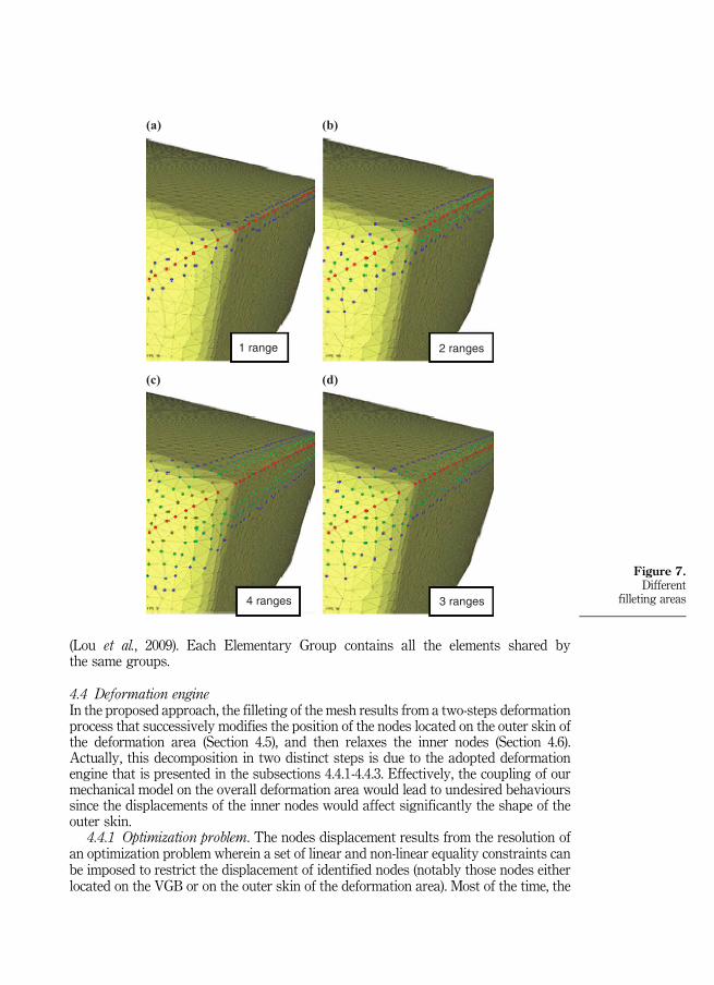
(Lou et al., 2009). Each Elementary Group contains all the elements shared bythe same groups.
4.4 Deformation engineIn the proposed approach, the filleting of the mesh results from a two-steps deformationprocess that successively modifies the position of the nodes located on the outer skin ofthe deformation area (Section 4.5), and then relaxes the inner nodes (Section 4.6).Actually, this decomposition in two distinct steps is due to the adopted deformationengine that is presented in the subsections 4.4.1-4.4.3. Effectively, the coupling of ourmechanical model on the overall deformation area would lead to undesired behaviourssince the displacements of the inner nodes would affect significantly the shape of theouter skin.
4.4.1 Optimization problem. The nodes displacement results from the resolution ofan optimization problem wherein a set of linear and non-linear equality constraints canbe imposed to restrict the displacement of identified nodes (notably those nodes eitherlocated on the VGB or on the outer skin of the deformation area). Most of the time, the
(a) (b)
(c) (d)
1 range 2 ranges
3 ranges4 ranges
Figure 7.Different
filleting areas

system to solve is under-constrained and an additional functional has to be minimizedthus defining a complete optimization problem:
G xð Þ ¼ 0
min/ xð Þ
((4)
wherein the vector x gathers together the coordinates of the free nodes (i.e. the nodeslocated in the deformation area), G(x)¼ 0 is the set of equations constraining some ofthe nodes, and ϕ(x) is the function to be minimized.
4.4.2 Objective functions. To produce realistic and smooth fillet, the adoptedobjective functions are built on top of a linear mechanical model of bar networkscoupled to the nodes and edges of the mesh (Pernot et al., 2006). Each edge can be seenas a spring with a null initial length li and with a stiffness qi. Therefore, to maintain thestructure in its initial static equilibrium state, external forces have to be applied tothe nodes and so that:
F ¼ gðxÞ (5)
wherein g is a linear mapping function linking the external forces F to the coordinatesof the free nodes x. At the opposite, the position of the free nodes can be obtained fromthe values of the external forces while using ɡ−1. In our implementation, the positions ofthe free nodes are considered as the unknown of the optimization problem.
To generate smooth fillet between the deformation area in the blocked area of themesh, two objective functions are here considered:
(1) the sum of the squared forces applied to the free nodes only:
/ xð Þ ¼ Sfreef2i (6)
(2) the sum of the squared forces applied to both the free and blocked nodes :
/ xð Þ ¼ Sfreef2i þSblockedf
2i (7)
The example of Figure 8(a) shows a simple structure made of eleven nodes forming aright angle. The four black nodes are blocked and all the other nodes are free to move.As illustrated, to maintain the initial static equilibrium state, three external forces areapplied. The minimization of the external forces applied to the free nodes (Equation 6)tends to produce a shape that has a minimal area (actually a minimal length in this 1Dexample) as illustrated on Figure 8(b). This minimization is called relaxation since itenables a repositioning of the nodes that minimizes all the forces applied to the structure.If the second objective function (Equation 7) is applied, the sharp corner is rounded with
(a) (b) (c)
Figure 8.Initial mesh (a) andresulting deformationaccording to thefree nodes (b) andall nodes (c)

respect to the area defined by the number of free nodes (Figure 8(c)). This minimizationtends to minimize the curvature variation between the blocked and free areas.
4.4.3 Constraints specification. To be able to maintain de shape of the VBG,geometric constraints are added to the optimization problem (equation 4). In the actualimplementation, free nodes are constrained to stay on planes, spheres and cylinders oron any intersection of these basic primitives:
Gp xið Þ ¼ xi�cð ÞUn ¼ 0
Gs xið Þ ¼ xi�cð Þ2�r2 ¼ 0
Gc xið Þ ¼ xi�cð Þ n̂½ �2�r2 ¼ 0(8)
wherein xi is the point that is constrained. The planar constraint restricts thedisplacement of xi to the plane defined by a point c and a normal n. The sphericalconstraint imposes xi to lie on a sphere of radius r centred in c. Finally, the cylindricalconstraint restricts the displacement of xi to a cylinder defined by its radius r and axisn going through a point c.
4.5 Surface mesh deformationAs introduced in Section 4.4, the filleting operator works in two successive deformationsteps: the outer skin deformation and the inner volume mesh relaxation. Both steps areapplied on the identified deformation area gathering together mesh elements in thesurrounding of identified sharp edges.
The first step aims at repositioning the nodes located on the outer skin of thedeformation area to smooth the normal evolution between the initial and deformedareas. Such a smoothing is obtained while using the objective function of Equation 7.This is illustrated on the example of Figure 9 which shows a section of a filleting area ofa tetrahedral mesh. The two cases of convex sharp corner (upper) and concave sharp
Blocked nodesInternal External
Sharp
Stretched
Interior
Sharp
(a) (b) (c)
(d) (e) (f)
Volume filleting area
Skindeformation
Interiorrelaxation
Figure 9.Two-step constrained
deformation fortetrahedral mesh
filleting for convexcorner (a), (b), (c)
and concavecorner (d), (e), (f)

corner (lower) are both illustrated in the Figure 9. Figure 9(a) and (d) correspond to theinitial configuration before deformation. The black edges are internal and the red edgesare skin elements. As illustrated on Figure 9(b) and (e), solely the nodes located on theskin of the deformation area are free to move. As highlighted on Figure 3 (c), solely theouter skin of the deformation area is smoothed thus producing several intersectionsbetween the skin and the inner elements (in dark on Figure 9) which have not yet beenrelaxed. In the Figure 9 (b) the same phenomena can be seen: some sharp edgeneighbour internal elements are coming out from the skin. In an opposite way, when thesharp corner is concave at beginning (Figure 9 (d)), the internal elements close to thesharp edges are stretched after the model skin deformation.
During the deformation process, some of the free nodes are also constrained to stayon certain surfaces in order to preserve the shape of the initial model and the VGB. Asstated in Section 3.2, before modifying the FE meshes our CAD-less framework willcompute the primitive surfaces for the initial models as well as for the VGB (Section4.3). The constraints are defined on the free nodes using the equations developed inSection 4.4.3. Thus the shapes of the model and of the groups can be preserved.
Figure 10 compares the results of deformation with and without constraints for theexample already illustrated in Figure 3. During the skin rounding deformation, thegroup boundary consists of a set of yellow edges that separate the two groups. TheVGB shape is broken (Figure 10 (a)) when the free nodes have moved withoutconstraints whereas the constrained deformation allows to preserve the shape of VGB(Figure 10 (b)).
Beside the shape of VGB the shape of the initial model is also concerned in thisexample. All the nodes on the two lateral sides should stay on the lateral plans in orderto keep the initial shape. If any constraints is defined on the free nodes (Figure 10 (c))the initial shape is broken and the lateral sharp curves (yellow edges) disappearedwhich should not be filleted. Figure 10 (d) shows the deformation under constraintswhere the lateral surface bounded by the yellow edges are kept planar.
4.6 Volume mesh relaxationIn the second deformation step, the nodes of the deformation area that have beenblocked during the first step are now free to move to adapt their positions inside thevolume mesh, whereas the nodes of the outer skin are now blocked. Here, we use theobjective function of Equation 6 to relax the positions of the nodes.
Coming back to the example of Figure 9, and after the outer skin deformation step(Figure 9 (b) and (e)), the volume mesh relaxation step is performed so that the positionof the deformation area inner nodes are relaxed (Figure 9(c) and (f )). Here, no constraintsare applied, and the optimization problem consists in the minimization of a quadraticfunction. On the example of Figure 3, a similar configuration is obtained on the innernodes of a volume deformation area. On this example, the inner free nodes are relaxed,and some of them are also constrained to stay on the plane defined by the VGB betweenthe two partitions (Figure 4(d)). The Figure 10(f ) displays solely the red volume groupand the faces bounded by the yellow edges composing the constrained VGB. If noconstraint is defined on the free nodes, the VGB faces close to the filleting area have losttheir initial shape (Figure 10(e)).
5. Results on academic and industrial examplesIn this section we report the results of the filleting operator applied to both academicand industrial semantically enriched parts.
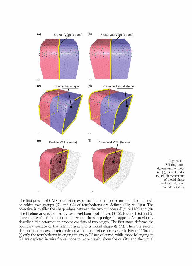
The first presented CAD-less filleting experimentation is applied on a tetrahedral mesh,on which two groups (G1 and G2) of tetrahedrons are defined (Figure 11(a)). Theobjective is to fillet the sharp edges between the two cylinders (Figure 11(b) and (d)).The filleting area is defined by two neighbourhood ranges (§ 4.2). Figure 11(c) and (e)show the result of the deformation where the sharp edges disappear. As previouslydescribed, the deformation process consists of two stages. The first stage deforms theboundary surface of the filleting area into a round shape (§ 4.5). Then the seconddeformation relaxes the tetrahedrons within the filleting area (§ 4.6). In Figure 11(b) and(c) only the tetrahedrons belonging to group G2 are coloured, while those belonging toG1 are depicted in wire frame mode to more clearly show the quality and the actual
(a) Preserved VGB (edges)Broken VGB (edges)
Preserved initial shape
(b)
(c) (d)
(e) (f)
Broken initial shape
Preserved VGB (faces)Broken VGB (faces)
Figure 10.Filleting mesh
deformation without(a), (c), (e) and under(b), (d), (f) constraints
of model shapeand virtual groupboundary (VGB)

group association in the resulting mesh. As depicted, the triangles defining the groupboundary of G1 and G2 (cf. VGB in Section 4.3) are inside the model and still maintaintheir initial shape (e.g. a plane in the present case).
In the second example, the presented CAD-less filleting experimentation is applied on atetrahedral mesh on which three groups (G1, G2 and G3) of tetrahedron are defined(Figure 12(a)). The sharp edge to round is between the group G2 and G3 (Figure 12(c)).Figure 12(b) shows the partial view of the initial model interior. In this example 5neighbourhood ranges are defined as filleting area (Figure 12(c)). The nodes selected in thefilleting area are displayed as bold green and blue points. Figure 12(e) shows the result ofthe deformation. The first stage deforms the boundary surface of the filleting area into around shape (Figure 12(d)) and any node inside is moved at this stage. Then, the seconddeformation repositions the internal nodes to relax the stretched tetrahedrons due tosurface deformation (Figure 12(f )). In this example the virtual group boundaries (VGB) thatare inside the model and separate the two groups G2 and G3maintain their initial shape (asshown in Figure 12(f )). At the same time, those external VGB nodes belonging to thefilleted area have been constrained to simultaneously be on the round shape defined by thefillet and on the planar surface defined the original VGB of the G2 and G3.
The third example (Figure 13(a)) consists in filleting sharp edges inside a caissonmodel. This model contains four tetrahedral groups that are displayed in four differentcolours. Figures 13(b), (c) and (d) give top views from the model. The sharp edges aredisplayed in Figure 13(c) and correspond to the connection with the bottom face ofcaisson interior. On the partial view on the model where only the red group is displayed
(d)
(e)
(b)
(c)
G1
G2
sharp edgesVGB
(a)
Figure 11.CAD-less filletingon a partitionedtetrahedral mesh
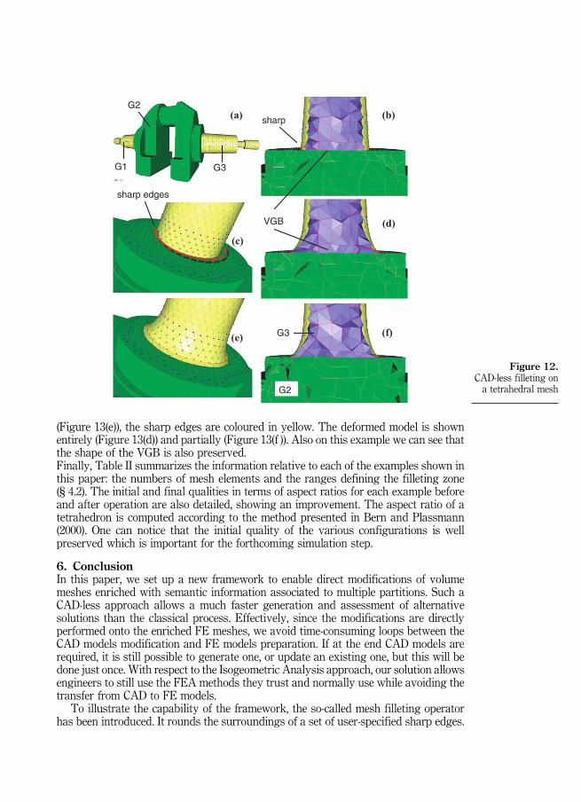
(Figure 13(e)), the sharp edges are coloured in yellow. The deformed model is shownentirely (Figure 13(d)) and partially (Figure 13(f )). Also on this example we can see thatthe shape of the VGB is also preserved.Finally, Table II summarizes the information relative to each of the examples shown inthis paper: the numbers of mesh elements and the ranges defining the filleting zone(§ 4.2). The initial and final qualities in terms of aspect ratios for each example beforeand after operation are also detailed, showing an improvement. The aspect ratio of atetrahedron is computed according to the method presented in Bern and Plassmann(2000). One can notice that the initial quality of the various configurations is wellpreserved which is important for the forthcoming simulation step.
6. ConclusionIn this paper, we set up a new framework to enable direct modifications of volumemeshes enriched with semantic information associated to multiple partitions. Such aCAD-less approach allows a much faster generation and assessment of alternativesolutions than the classical process. Effectively, since the modifications are directlyperformed onto the enriched FE meshes, we avoid time-consuming loops between theCAD models modification and FE models preparation. If at the end CAD models arerequired, it is still possible to generate one, or update an existing one, but this will bedone just once. With respect to the Isogeometric Analysis approach, our solution allowsengineers to still use the FEA methods they trust and normally use while avoiding thetransfer from CAD to FE models.
To illustrate the capability of the framework, the so-called mesh filleting operatorhas been introduced. It rounds the surroundings of a set of user-specified sharp edges.
(a) (b)
(c) (d)
(e)
G2
G1 G3
sharp edges
VGB
sharp
G2
G3 (f)
Figure 12.CAD-less filleting ona tetrahedral mesh

The final shape results from a two-step deformation process which first workson the skin of the mesh before relaxing inner nodes in an identified deformation area.During the smoothing process, some nodes might have to fulfil additional constraintsdepending on whether they are located on a VGB or not. Therefore, this operator notonly works at the level of the mesh elements, but also takes into account semanticinformation attached to multiple partitions of the mesh. This is a real breakthrough inthe way FE meshes can be manipulated directly with respect to the existingapproaches, i.e. guaranteeing the mesh geometric quality and preserving the FEknowledge during the mesh modification steps.
However, several improvements are foreseen. At the geometric level, thedeformation area, i.e. the part of the mesh that has to be rounded, will be computed
(a)
(b)
(c)
(d)
(f)
(e)
Sharp edges
Figure 13.CAD-less filleting ona tetrahedral mesh
Meshes Cube Cylinder Meca CaissonCriteria (Figure 4) (Figure 11) (Figure 12) (Figure 13)
Nb. nodes 2,244 4,468 21,805 16,733Nb. tetras 9,598 18,938 92,985 66,777Range 3 2 5 3Qinit 0.698 0.675 0.705 0.657Qfinal 0.690 0.669 0.700 0.649
Table II.Comparison of theaspect ratio Q (Bernand Plassmann,2000) for the variousfilleted models

directly from a user-specified filleting radius. Actually, along the sharp edges, thenumber of ranges used to define the deformation area should vary according to thedensity of the surrounding mesh elements. To better approximate the user-specifiedfilleting radius, whatever the mesh density is, the use of mesh enrichment could beexploited. Moreover, new developments for overcoming problems due to noisy meshesin the sharp edges computation (i.e. propagation in the surrounding of a user-specifiedreference sharp edge) will be undertaken.
At the semantic level, future works concern the improvement of the treatment andtransfer of the semantic information through a set of rules such as inheritance,propagation, etc. Actually, the actual developed filleting operator does not yet work on theFE semantics attached to the groups but rather on the type of shape associated to VGBwhich is already an improvement in the way enriched FE meshes are manipulated.
Finally, such a modelling approach could also be extended to other operators or toother simulations such as topological optimization.
ReferencesAttene, M., Falcidieno, B. and Spagnuolo, M. (2006), “Hierarchical mesh segmentation based on
fitting primitives”, J. Visual Computer, Vol. 22 No. 3, pp. 181-193.Bern, M. and Plassmann, P. (2000), “Mesh generation”, in Sack, J.-R. and Urruita, J. (Eds),
Handbook of Computational Geometry, Elsevier Science Publishers B.V., North-Holland,Amsterdam, pp. 291-332.
Biermann, H., Kristjansson, D. and Zorin, D. (2001), “Approximate boolean operations onfree-form solids”, Proc. of the 28th Annual Conference on Computer graphics and InteractiveTechniques, SIGGRAPH ‘01, pp. 185-194.
Bremberg, D. and Dhondt, G. (2008), “Automatic crack-insertion for arbitrary crack growth”,Engineering Fracture Mechanics, Vol. 75 Nos 3/4, pp. 404-416.
Chen, Y. (2007), “Robust and accurate boolean operations on polygonal models”, Proc. of ASMEDesign Engineering Technical Conferences, Volume 2: 27th Computers and Information inEngineering Conference, Las Vegas, Nevada, 4–7 September.
Chen, Y. and Wang, C.C.L. (2011), “Uniform offsetting of polygonal model based on layereddepth-normal images”, Int. J. CAD, Vol. 43 No. 1, pp. 31-46.
Chen, Y., Wang, H., Rosen, D.-W. and Rossignac, J. (2005), “Filleting and rounding using a point-basedmethod”, Proc. of DETC'05, ASME Design Engineering Technical Conferences and Computersand Information in Engineering Conference, Long Beach, CA, 24-28 September, pp. 1-10.
Chouadria, R. and Veron, P. (2006), “Identifying and re-meshing contact interfaces in a polyhedralassembly for digital mock-up”, J. of Engineering with Computer, Vol. 22 No. 1, pp. 47-58.
Ciarlet, P.G. (1978), The Finite Element Method for Elliptic Problems, North-Holland, Amsterdam,New York, Oxford.
Cottrell, J.A., Hughes, T.J.R. and Bazilevs, Y. (2009), Isogeometric Analysis: Towards Integration ofCAD and FEM, John Wiley & Sons, Chichester.
Dakowicz, M. and Gold, C. (2005), “Interactive tin modification with a cutting tool”, Proc. of 4thISPRS Workshop on Dynamic and Multi-dimensional GIS, Pontypridd, Wales, pp. 5-9.
Gatzke, T. and Grimm, C. (2006), “Estimating curvature on triangular meshes”, Int. J. IJSM,Vol. 12 No. 1, pp. 1-29.
Hui, K.C. and Lai, Y.H. (2006), “Smooth blending of subdivision surfaces”, Int. J. CAD, Vol. 38No. 7, pp. 786-799.
Igarashi, T. and Hughes, J.F. (2003), “Smooth meshes for sketch-based freeform modeling”, Proc.ACM Symposium on Interactive 3D Graphics, Monterey, CA, pp. 139-142.

Jin, X., Lin, J., Wang, C.C.L. and Feng, J. (2006), “Hanqiu sun: mesh fusion using functional blendingon topologically incompatible sections”, Visual Computer, Vol. 22 No. 4, pp. 266-275.
Jung, W., Shin, H. and Choi, B.K. (2004), “Self-intersection removal in triangular mesh offsetting”,Computer-Aided Design and Applications, Vol. 1 Nos 1/4, pp. 477-484.
Kim, S.-J. and Yang, M.-Y. (2005), “Triangular mesh offset for generalized cutter”, Int. J. CAD,Vol. 37 No. 10, pp. 999-1014.
Kim, S.J., Lee, D.Y. and Yang, M.Y. (2004), “Offset triangular mesh using the multiple normalvectors of a vertex”, Computer-Aided Design and Applications, Vol. 1 Nos 1/4, pp. 285-292.
Lee, S.H., Lee, W.K. and Lee, K.-S. (2001), “Rounding operations on shell meshes for efficientanalysis of stamping tools for automotive body panels”, Proc. of the 11th InternationalPacific Conference on Automotive Engineering (IPC-11), 6-9 November.
Lesage, D., Léon, J.-C. and Véron, P. (2005), “Discrete curvature approximations and segmentationof polyhedral surface”, Int. J. IJSM, Vol. 11 No. 2, pp. 217-252.
Liu, Y., Zhang, H., Yong, J., Yu, P. and Sun, J. (2005), “Mesh blending”, The Visual Computer,Vol. 21 No. 11, pp. 915-927.
Loop, C. (1987), “Smooth subdivision surfaces based on triangles”, M.S. Mathematics thesis,University of Utah, Salt Lake City, UT.
Lou, R., Mikchevitch, A., Pernot, J.-P. and Véron, P. (2010a), “Merging enriched finite elementtriangle meshes for fast prototyping of alternate solutions in the context of industrialmaintenance”, Int. J. CAD, Vol. 42 No. 8, pp. 670-681.
Lou, R., Pernot, J.-P., Giannini, F., Véron, P. and Falcidieno, B. (2012), “Sharp edge filleting ofenriched FE meshes”, Proc. of TMCE 2012, Karlsruhe.
Lou, R., Giannini, F., Pernot, J.-P., Mikchevitch, A., Véron, P., Falcidieno, B. and Marc, R. (2009),“Towards CAD-less finite element analysis using group boundaries for enriched meshesmanipulation”, Proc. of ASME 2009 IDETC & CIE, Vol. 2, San Diego, CA, pp. 29-38.
Lou, R., Giannini, F., Pernot, J.-P., Mikchevitch, A., Véron, P., Falcidieno, B. and Marc, R. (2010b),“Direct modification of semantically-enriched finite element meshes”, Int. J. IJSM, Vol. 16Nos 1/2, pp. 81-108.
Mao, Z., Cao, G., Ma, Y. and Kunwoo, L. (2011), “Curvature estimation for meshes based on vertexnormal triangles”, J. Computer-Aided Design, Vol. 43 No. 12, pp. 1561-1566.
Pavic, D. and Kobbelt, L. (2008), “High-resolution volumetric computation of offset surfaces withfeature preservation”, Computer Graphics Forum, Vol. 27 No. 2, pp. 165-174.
Pernot, J.-P., Moraru, G. and Véron, P. (2006), “Filling holes in meshes using a mechanical model tosimulate the curvature variation minimization”, Computers & Graphics, Vol. 30 No. 6,pp. 892-902.
Premysl, K. (2002), “Complex human tissues femmodels prepared by boolean operations”,Biomechanicsof Man, Faculty of Physical Education and Sport Charles University in Prague, pp. 24-26.
Turini, G., Ganovelli, F. and Montani, C. (2006), “Simulating drilling on tetrahedral meshes”, Proc.of Eurographics Conference, pp. 127-131.
Whited, B. and Rossignac, J. (2009), “Relative blending”, Computer-Aided Design, Vol. 41 No. 6,pp. 456-462.
Corresponding authorAssistant Professor Ruding Lou can be contacted at: [email protected]