figure 8.1 csma/cd worst-case collision detection
TRANSCRIPT

Figure 8.1 CSMA/CD worst-case collision detection.
© Pearson Education Limited 2001

Figure 8.2 Hub configuration principles: (a) topology; (b) repeater schematic.
© Pearson Education Limited 2001

Figure 8.3 Ethernet/IEEE802.3 characteristics: (a) frameformat; (b) operational parameters.
© Pearson Education Limited 2001
Type/Length
2
SA
2/6
SFD
1
DA
2/6
Preamble
7Bytes
FCS
4
Data
46/1500
60/1512 bytes
I/G
1
L/C
1Bits 14/46
SFD = start-of-frame delimiterDA/SA = source/destination addressI/G = individual (=0)/group (=1) address
FCS = frame check sequenceL/C = locally administered (=1)/
centrally administered (=0)
Bit rateSlot timeInterframe gapAttempt limitBack off limitJam sizeMaximum frame size (including FCS)Minimum frame size (including FCS)
10 Mbps (Manchester encoded)512 bit times9.6 microseconds161032 bits1518 bytes512 bits
(a)
(b)
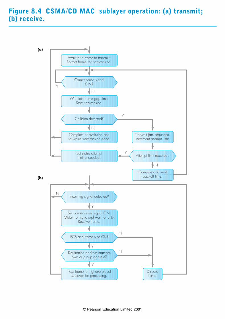
Figure 8.4 CSMA/CD MAC sublayer operation: (a) transmit; (b) receive.
© Pearson Education Limited 2001

Figure 8.5 Token ring network: principle of operation.
© Pearson Education Limited 2001
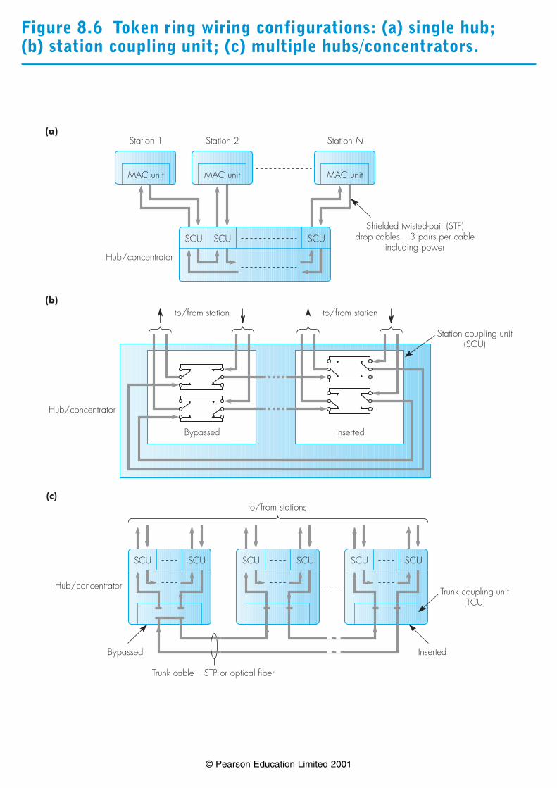
Figure 8.6 Token ring wiring configurations: (a) single hub; (b) station coupling unit; (c) multiple hubs/concentrators.
© Pearson Education Limited 2001
MAC unit
Station 1
MAC unit
Station 2
MAC unit
Station N
SCU SCUSCU
Hub/concentrator
Shielded twisted-pair (STP)drop cables – 3 pairs per cable
including power
(a)
SCUSCU
Hub/concentrator
Inserted
(b)
SCUSCU SCUSCU
Bypassed
Trunk cable – STP or optical fiber
Trunk coupling unit(TCU)
to/from stations
to/from station to/from station
Bypassed Inserted
Station coupling unit(SCU)
Hub/concentrator
(c)
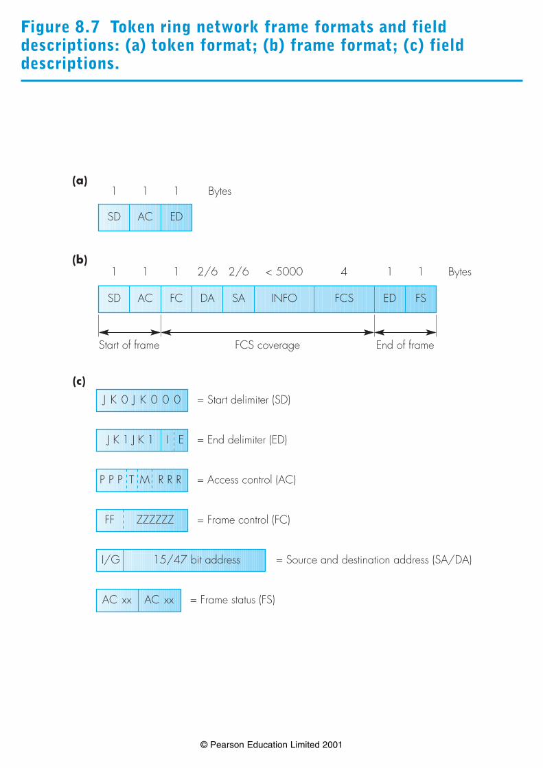
Figure 8.7 Token ring network frame formats and fielddescriptions: (a) token format; (b) frame format; (c) fielddescriptions.
© Pearson Education Limited 2001

Figure 8.8 Token ring MAC sublayer operation: (a) transmit; (b) receive.
© Pearson Education Limited 2001

Figure 8.9 Token generation and stack modifications: (a) tokengeneration [Note: Sx = 0 if stack empty]; (b) stackmodification.
© Pearson Education Limited 2001
Frame(s) queued and token received with P < Pm
Transmit queued (waiting) frame(s) with P = Pr and R = 0
Token (P = Rr/Pm, R = 0)PUSH Pr to SrPUSH P to Sx
Token (P = Rr/Pm, R = 0)POP SxPUSH P to Sx
Token (P = Pr, R = Rr/Pm)
Pr < Rr/Pm and Pr > Sx Pr < Rr/Pm and Pr = SxPr > Rr/Pm
Transmit token
(a)
Token received with P = Sx
Token (P = Sr, R = Rr)POP Sx and SrIf Sx and Sr empty, cease stacking
Token (P = Rr, R = 0)PUSH P to SxContinue stacking
Rr < SrRr > Sr
Transmit token
(b)

Figure 8.10 Token ring priority example.
© Pearson Education Limited 2001
Station1Pm = 2F/T (P, R)Rotation
Station7Pm = 2F/T (P, R)
Station15Pm = 4F/T (P, R)
Station17Pm = 4F/T (P, R)
T(0, 0)0 T(0, 0) T(0, 0) T(0, 0)
T(0, 0)Pr = 0, Rr = 0, Pm = 2Pm > PrF(0, 0)P = Pr = 0; Rr = 0
F(0, 0)Pr = 0, Rr = 0, Pm = 2Pm > RrF(0, 2)P = Pr = 0; R = Pm = 2
F(0, 2)Pr = 0, Rr = 2, Pm = 4Pm > PrF(0, 4)P = Pr = 0; R = Pm = 4
F(0, 4)Pr = 0, Rr = 4, Pm = 4Pm = RrF(0, 4)P = Pr = 0; R = Rr = 4
1
F(0, 4)Pr = 0, Rr = 4Rr > PrT(4, 0)P = Rr = 4; R = 0
T(4, 0)Pr = 4, Rr = 0, Pm = 2Pr > Pm > RrT(4, 2)P = Pr; R = Pm = 2
T(4, 2)Pr = 4, Rr = 2, Pm = 4Pm = PrF(4, 0)P = Pr = 4; R = 0
F(4, 0)Pr = 4, Rr = 0, Pm = 4Pm > RrF(4, 4)P = Pr; R = Pm = 4
2
Stacking St = 0, Sx = 4
F(4, 4)no frame totransmitF(4, 4)
F(4, 4)Pr = 4, Rr = 4, Pm = 2Pr < RrF(4, 4)P = Pr; R = Rr
F(4, 4)Pr = 4, Rr = 4Rr = PrT(4, 4)P = Pr = 4; R = Rr = 4
T(4, 4)Pr = 4, Rr = 4, Pm = 4Pm = PrF(4, 0)P = Pr; R = 0
3
Sr = 0, Sx = 4
F(4, 0)no frame totransmitF(4, 0)
F(4, 0)Pr = 4, Rr = 0, Pm = 2Pm > RrF(4, 2)P = Pr; R = Pm
F(4, 2)no frame totransmitF(4, 2)
F(4, 2)Pr = 4, Rr = 2Rr < PrT(4, 2)P = Pr; R = Rr
4
Sr = 0, Sx = 4
T(4, 2)Pr = 4, Rr = 2, Sr = 0, Sx = 4Pr = Sx, Rr > SrT(2, 0)P = Pr = 2; R = 0
T(2, 0)Pr = 2, Rr = 0, Pm = 2Pr = PrF(2, 0)P = Pr; R = Rr
F(2, 0)no frame totransmitF(2, 0)
F(2, 0)no frame totransmitF(2, 0)
5
Sr = 0, Sx = 2
F(2, 0)no frame totransmitF(2, 0)
F(2, 0)Pr = 2, Rr = 0Rr < PrT(2, 0)P = Pr; R = Rr
T(2, 0)no frame totransmitF(2, 0)
F(2, 0)no frame totransmitF(2, 0)
6
Sr = 0, Sx = 2
T(2, 0)Pr = 2, Rr = 2, Sr = 0, Sx = 2Pr = Sx, Rr < SrT(0, 0)P = Sr; R = Rr
T(0, 0)no frame totransmitT(0, 0)
T(0, 0)no frame totransmitT(0, 0
7
Cease stacking
T(0, 0)no frame totransmitT(0, 0
T(0, 0) T(0, 0) T(0, 0)8 T(0, 0)

Figure 8.11 LAN interconnection: (a) repeaters; (b) bridges.
© Pearson Education Limited 2001
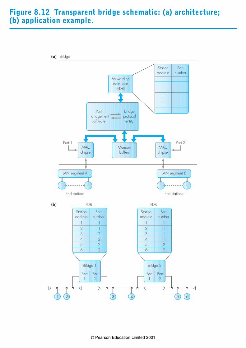
Figure 8.12 Transparent bridge schematic: (a) architecture; (b) application example.
© Pearson Education Limited 2001

Figure 8.13 Effect of dual paths on learning algorithm.
© Pearson Education Limited 2001

Figure 8.14 Active topology derivation example: (a) LANtopology; (b) root port selection; (c) designated port selection; (d) active topology.
© Pearson Education Limited 2001
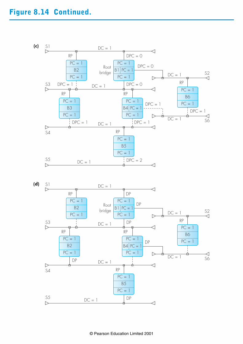
Figure 8.14 Continued.
© Pearson Education Limited 2001

Figure 8.15 An example source routing bridged LAN: (a) topology; (b) routing table entries.
© Pearson Education Limited 2001

Figure 8.16 Token ring frame format: (a) position of routinginformation field; (b) structure of routing information field.
© Pearson Education Limited 2001

Figure 8.17 Source routing example: (a) topology; (b) spanningtree.
© Pearson Education Limited 2001
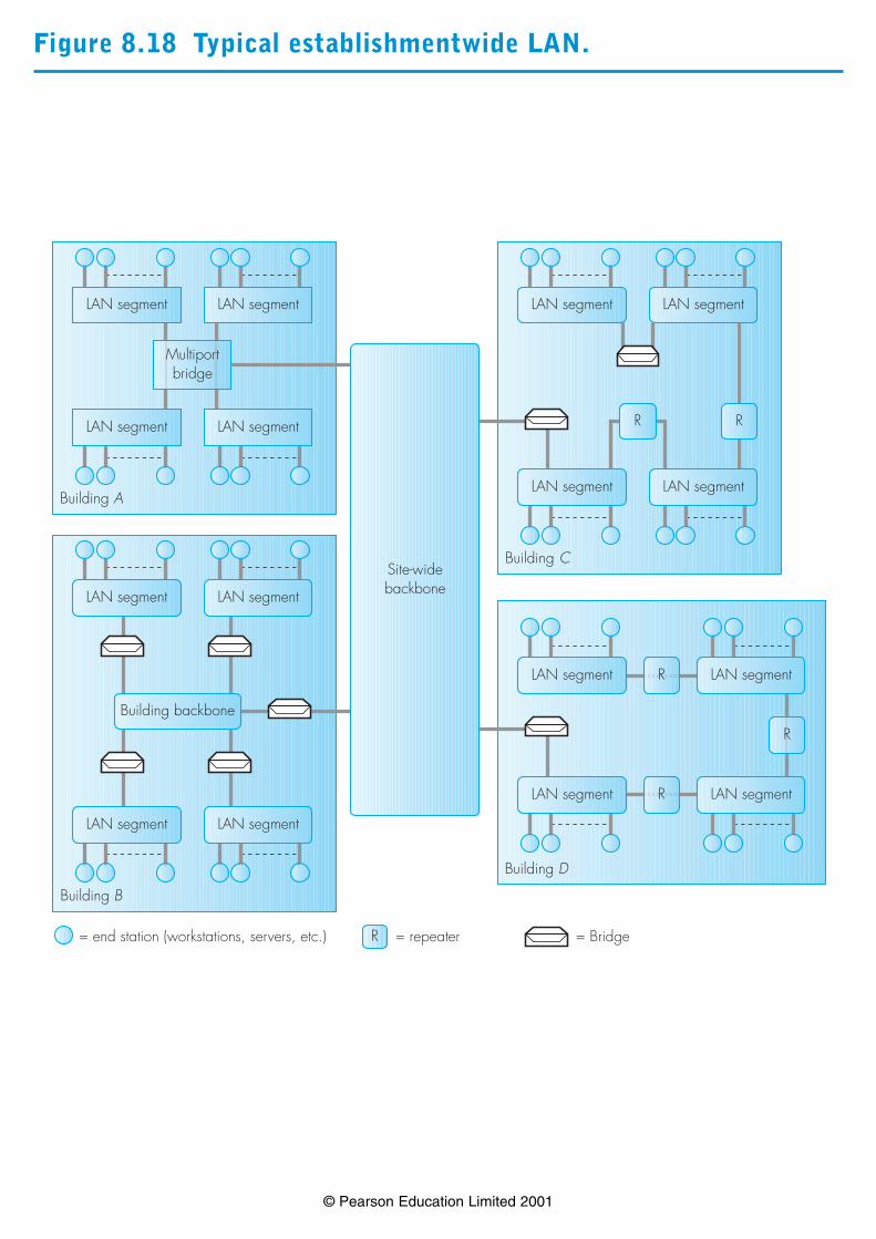
Figure 8.18 Typical establishmentwide LAN.
© Pearson Education Limited 2001

Figure 8.19 FDDI networking components.
© Pearson Education Limited 2001

Figure 8.20 Ring fault detection and isolation: (a) failuredetection; (b) redundant ring configuration; (c) segmentisolation; (d) station isolation.
© Pearson Education Limited 2001
TCU = trunk coupling units

Figure 8.21 FDDI wiring schematic: (a) building; (b) establishment.
© Pearson Education Limited 2001

Figure 8.22 FDDI physical interface schematic.
© Pearson Education Limited 2001

Figure 8.23 FDDI line coding and framing detail: (a) 4B5Bcodes; (b) frame formats.
© Pearson Education Limited 2001
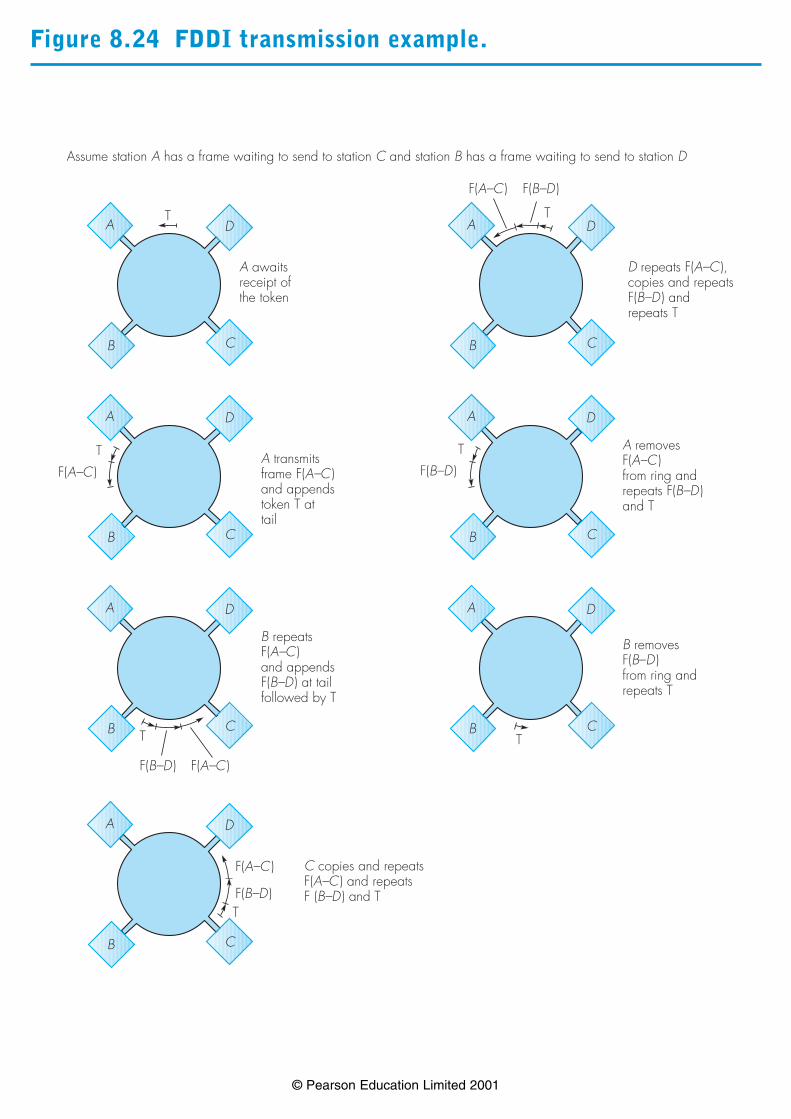
Figure 8.24 FDDI transmission example.
© Pearson Education Limited 2001
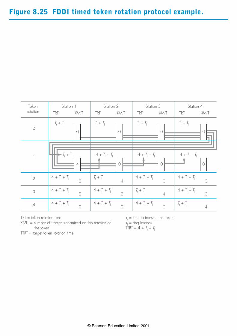
Figure 8.25 FDDI timed token rotation protocol example.
© Pearson Education Limited 2001
4 + Tt + Tl
0 0 0
0 0 0
Tokenrotation
Station 1
TRT XMIT
Station 2
TRT XMIT
Station 3
TRT XMIT
Station 4
TRT XMIT
Tt + Tl
0
4 + Tt + Tl0
4 + Tt + Tl0
4 + Tt + Tl0
Tt + Tl4
4 + Tt + Tl0
4 + Tt + Tl0
4 + Tt + Tl0
Tt + Tl4
4 + Tt + Tl0
4 + Tt + Tl0
4 + Tt + Tl0
Tt + Tl44
3
2
1
0
TRT = token rotation timeXMIT = number of frames transmitted on this rotation of
the tokenTTRT = target token rotation time
Tt + Tl Tt + Tl Tt + Tl
Tt + Tl 4 + Tt + Tl 4 + Tt + Tl
Tt = time to transmit the tokenTl = ring latencyTTRT = 4 + Tt + Tl
4
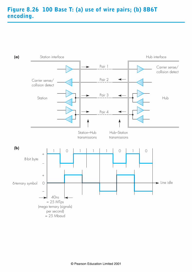
Figure 8.26 100 Base T: (a) use of wire pairs; (b) 8B6Tencoding.
© Pearson Education Limited 2001
Pair 1
Pair 2
Pair 3
Pair 4
Station–Hubtransmissions
Hub–Stationtransmissions
Carrier sense/collision detect
Station
Station interface
Carrier sense/collision detect
Hub
Hub interface
+
–
+
0
–
1 0 1 1 1 0 1 0
40ns= 25 MTps
(mega ternary (signals)per second)
= 25 Mbaud
Line idle
8-bit byte
6-ternary symbol
(a)
(b)

Figure 8.27 100BaseT transmission detail: (a) DC balancetransmission rules; (b) 8B6T encoding sequence; (c) end ofstream encoding.
© Pearson Education Limited 2001
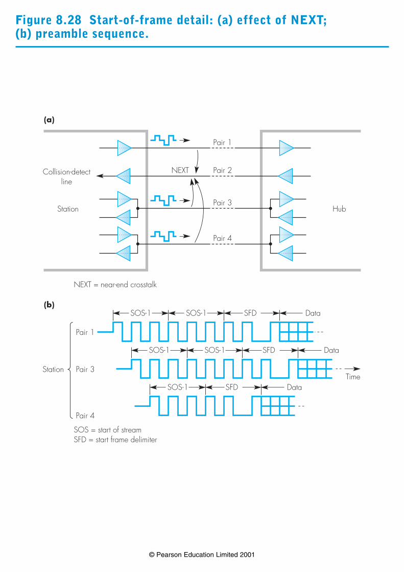
Figure 8.28 Start-of-frame detail: (a) effect of NEXT; (b) preamble sequence.
© Pearson Education Limited 2001
Pair 1
Pair 2
Pair 3
Pair 4
NEXT = near-end crosstalk
Collision-detectline
Station Hub
(a)
NEXT
Pair 1
Pair 3
Pair 4
SOS-1 SOS-1 SFD Data
SOS-1 SOS-1 SFD Data
SOS-1 SFD Data
(b)
Station
SOS = start of streamSFD = start frame delimiter
Time

Figure 8.29 Fast Ethernet switch schematic.
© Pearson Education Limited 2001
Switch memory LOU 1 LOU NLIU N
Control processor
StationN
Station1
Dual 100 Mbps drop cables
LIU = line input unitLOU = line output unit
Fast Ethernet switch
LIU 1

Figure 8.30 Example network configuration with a FastEthernet switch and 10/100BaseT hubs.
© Pearson Education Limited 2001
Fast Ethernet switch
10 Base T Hub
Stations
100 Base T Hub
Stations
100 Base T Hub
Stations
ServerServer
10/100Mbps (CSMA/CD) half-duplex lines100Mbps duplex lines

Figure 8.31 LAN protocols: (a) protocol framework; (b) examples.
© Pearson Education Limited 2001
Transmission medium
Physical medium-dependent sublayer
Convergence sublayer
MAC sublayer
LLC sublayer
Network layer
Physical layer
Link layer
(b)
(a)
IEEE 802.1 Station management802.1d Transparent bridges
802.2 Logical link control (LLC)
802.3 CSMA/CD (Ethernet) bus802.3u Fast Ethernet802.3x Hop-by-hop switch flow control802.3z Gigabit Ethernet
802.5 Token ring
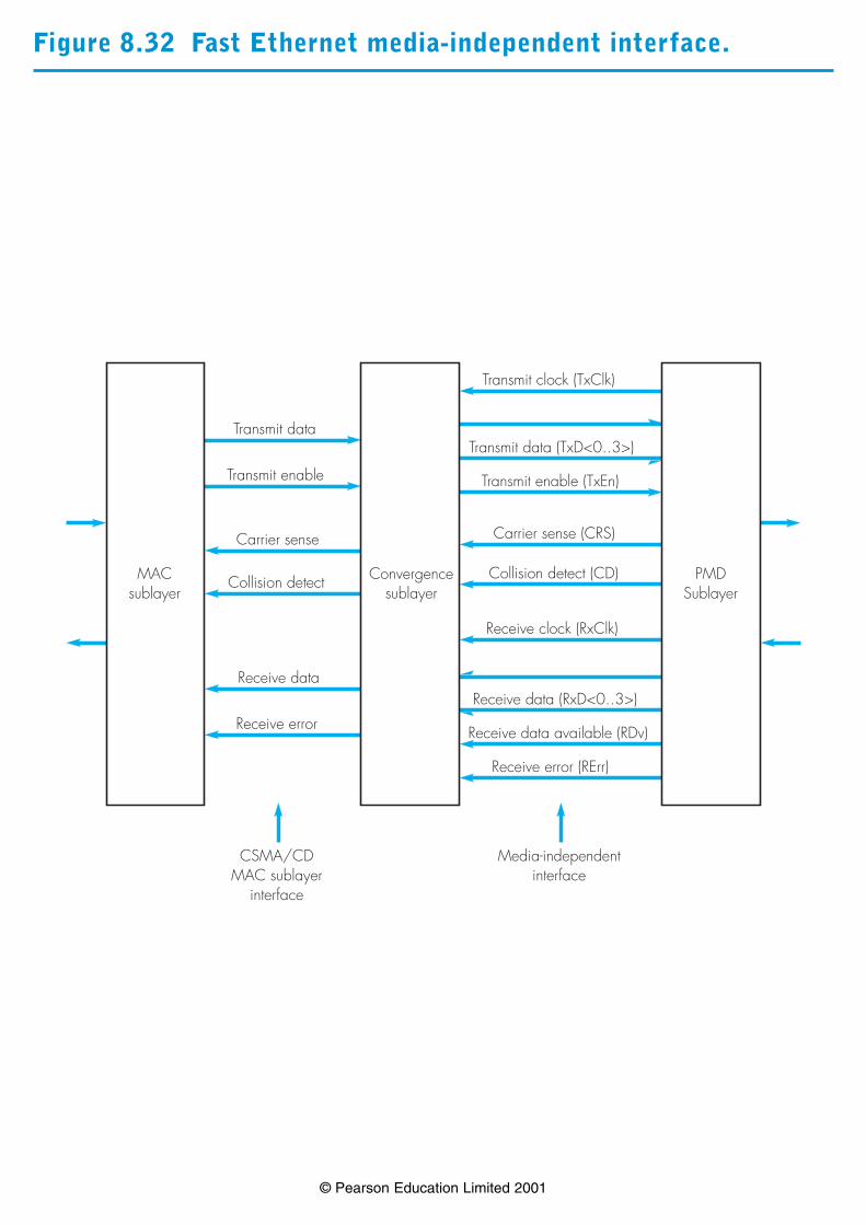
Figure 8.32 Fast Ethernet media-independent interface.
© Pearson Education Limited 2001
Transmit data
Transmit enable
Carrier sense
Collision detect
Receive data
Receive error
Transmit clock (TxClk)
Transmit data (TxD<0..3>)
Transmit enable (TxEn)
Carrier sense (CRS)
Collision detect (CD)
Receive clock (RxClk)
Receive data (RxD<0..3>)
Receive data available (RDv)
Receive error (RErr)
CSMA/CDMAC sublayer
interface
Media-independentinterface
MACsublayer
Convergencesublayer
PMDSublayer

Figure 8.33 MAC user service primitives: (a) CSMA/CD; (b) token ring.
© Pearson Education Limited 2001
LLC layer Correspondent’sLLC layer
MAC layer
MA_UNITDATA.request
MA_UNITDATA.confirm
MA_UNITDATA.request
MA_UNITDATA.confirm
MA_UNITDATA.indication
MA_UNITDATA.indication
(a)
(b)

Figure 8.34 LLC/MAC sublayer interactions.
© Pearson Education Limited 2001
MAC LLC
MA_UNITDATA.ind(UI)
MA_UNITDATA.req(UI)
Network
L_DATA.indication(NPDU)
L_DATA.request(NPDU)
Network
L_DATA.indication(NPDU)
L_DATA.request(NPDU)
LLC
MA_UNITDATA.ind(UI)
MA_UNITDATA.req(UI)
Source DTE Destination DTE
NPDU = network layer protocol data unit

Figure 8.35 Interlayer primitives and parameters.
© Pearson Education Limited 2001
ECB = event control block

Figure 8.36 Example enterprise network architecture.
© Pearson Education Limited 2001
GW
Site LAN
SiteLANGWGW
SiteLAN
Intersite communications facility
GW = intersite gateway (remote bridge or IP/IPX router)
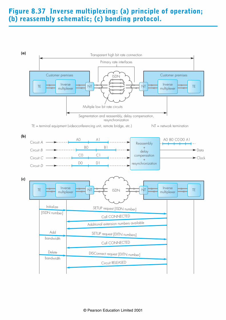
Figure 8.37 Inverse multiplexing: (a) principle of operation; (b) reassembly schematic; (c) bonding protocol.
© Pearson Education Limited 2001
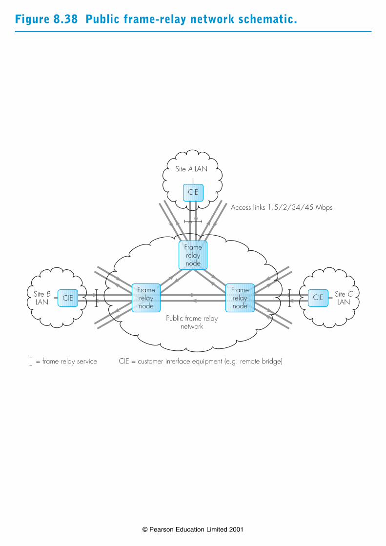
Figure 8.38 Public frame-relay network schematic.
© Pearson Education Limited 2001
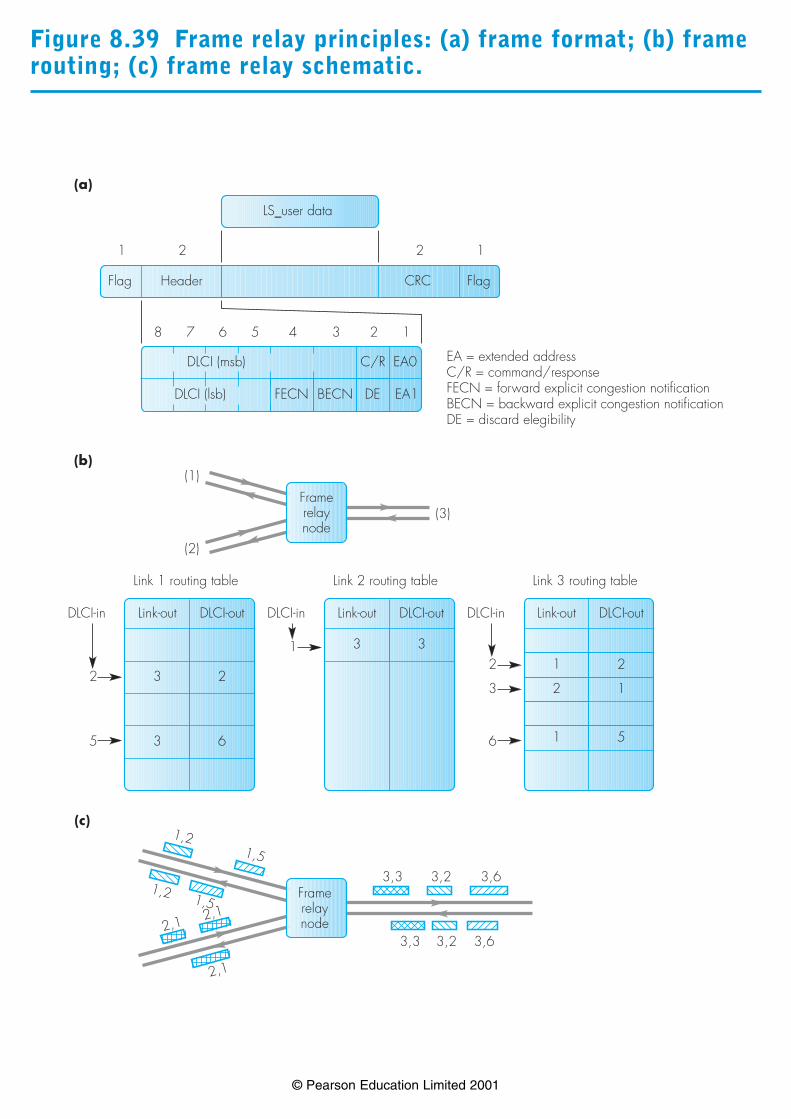
Figure 8.39 Frame relay principles: (a) frame format; (b) framerouting; (c) frame relay schematic.
© Pearson Education Limited 2001
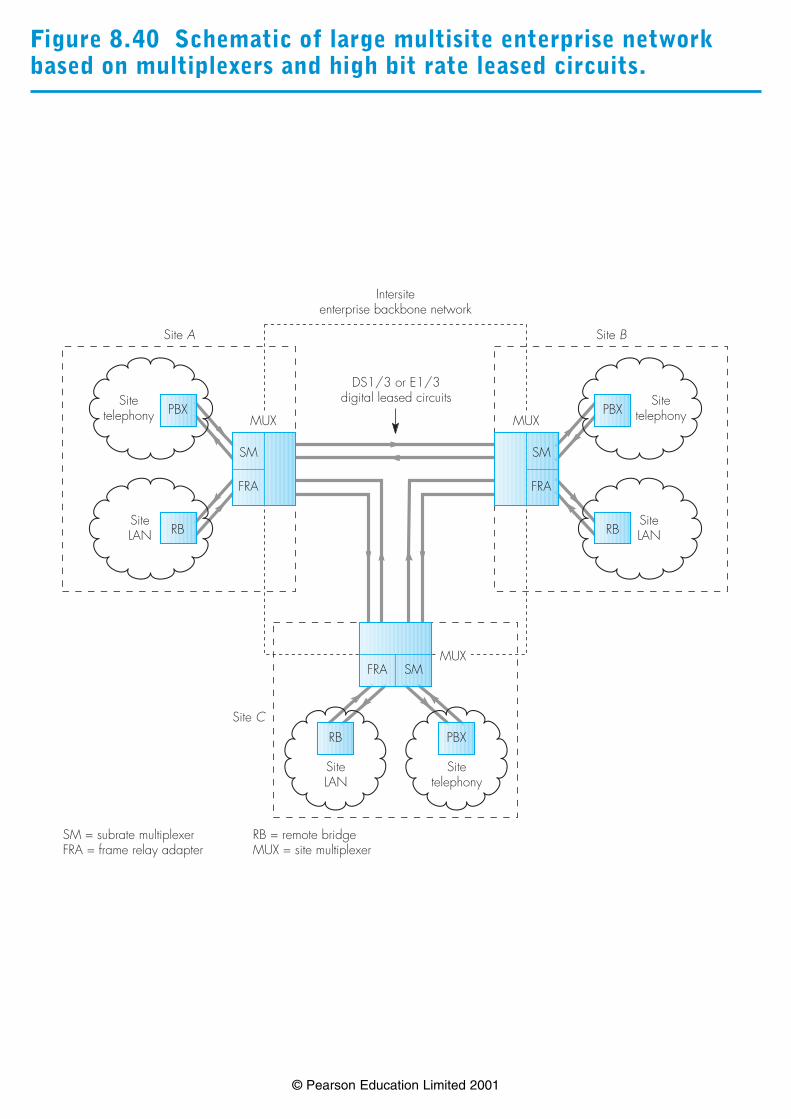
Figure 8.40 Schematic of large multisite enterprise networkbased on multiplexers and high bit rate leased circuits.
© Pearson Education Limited 2001
PBX
Sitetelephony
RB
SiteLAN
SMFRA
Site C
PBXSite
telephony
RBSiteLAN
SM
FRA
Site B
PBXSite
telephony
RBSiteLAN
SM
FRA
Site A
Intersiteenterprise backbone network
DS1/3 or E1/3digital leased circuits
MUXMUX
MUX
SM = subrate multiplexerFRA = frame relay adapter
RB = remote bridgeMUX = site multiplexer

Figure 8.41 Summary of the topics discussed in this chapterrelating to enterprise networks.
© Pearson Education Limited 2001
Summary
Enterprise networks
LANs (data)PBX (telephony)(Chapter 7)
Legacy LANs
Ethernet Token ring
LAN interconnection
Transparentbridges
Source routingbridges
FDDI backbonenetworks
High-speed LANs
Fast Ethernethubs/repeaters
GigabitEthernet
Fast Ethernetswitches
Enterprise LAN interconnection technologies
Remote bridges/routers(Chapter 9)
Multisite enterprise network example
ISDN connections Frame relay High bit rate leased circuits
Example 8.1
© Pearson Education Limited 2001
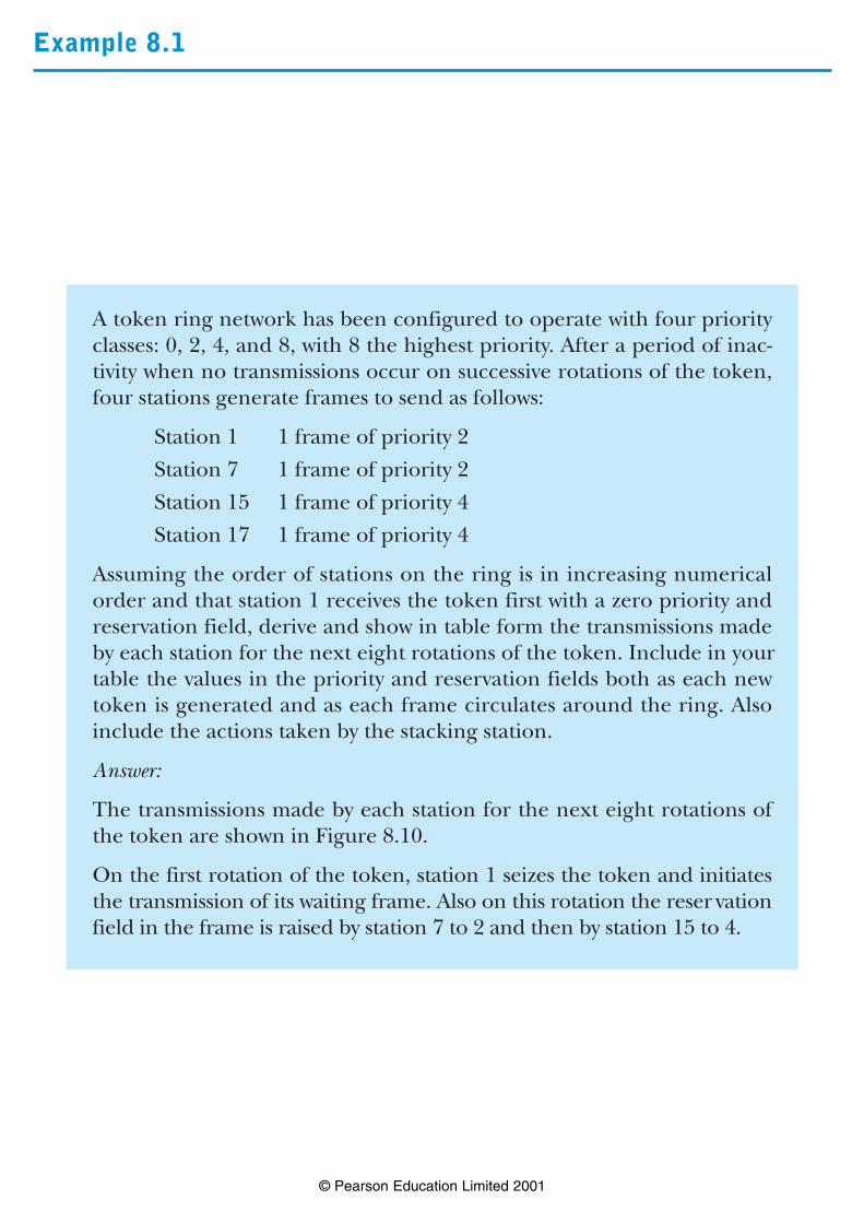
A token ring network has been configured to operate with four priorityclasses: 0, 2, 4, and 8, with 8 the highest priority. After a period of inac-tivity when no transmissions occur on successive rotations of the token,four stations generate frames to send as follows:
Station 1 1 frame of priority 2
Station 7 1 frame of priority 2
Station 15 1 frame of priority 4
Station 17 1 frame of priority 4
Assuming the order of stations on the ring is in increasing numericalorder and that station 1 receives the token first with a zero priority andreservation field, derive and show in table form the transmissions madeby each station for the next eight rotations of the token. Include in yourtable the values in the priority and reservation fields both as each newtoken is generated and as each frame circulates around the ring. Alsoinclude the actions taken by the stacking station.
Answer:
The transmissions made by each station for the next eight rotations ofthe token are shown in Figure 8.10.
On the first rotation of the token, station 1 seizes the token and initiatesthe transmission of its waiting frame. Also on this rotation the reser vationfield in the frame is raised by station 7 to 2 and then by station 15 to 4.
8.1 Continued
© Pearson Education Limited 2001
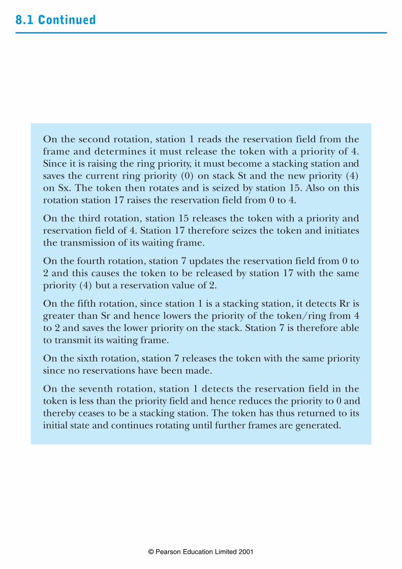
On the second rotation, station 1 reads the reservation field from theframe and determines it must release the token with a priority of 4.Since it is raising the ring priority, it must become a stacking station andsaves the current ring priority (0) on stack St and the new priority (4)on Sx. The token then rotates and is seized by station 15. Also on thisrotation station 17 raises the reservation field from 0 to 4.
On the third rotation, station 15 releases the token with a priority andreservation field of 4. Station 17 therefore seizes the token and initiatesthe transmission of its waiting frame.
On the fourth rotation, station 7 updates the reservation field from 0 to2 and this causes the token to be released by station 17 with the samepriority (4) but a reservation value of 2.
On the fifth rotation, since station 1 is a stacking station, it detects Rr isgreater than Sr and hence lowers the priority of the token/ring from 4to 2 and saves the lower priority on the stack. Station 7 is therefore ableto transmit its waiting frame.
On the sixth rotation, station 7 releases the token with the same prioritysince no reservations have been made.
On the seventh rotation, station 1 detects the reservation field in thetoken is less than the priority field and hence reduces the priority to 0 andthereby ceases to be a stacking station. The token has thus returned to itsinitial state and continues rotating until further frames are generated.
Example 8.2
© Pearson Education Limited 2001
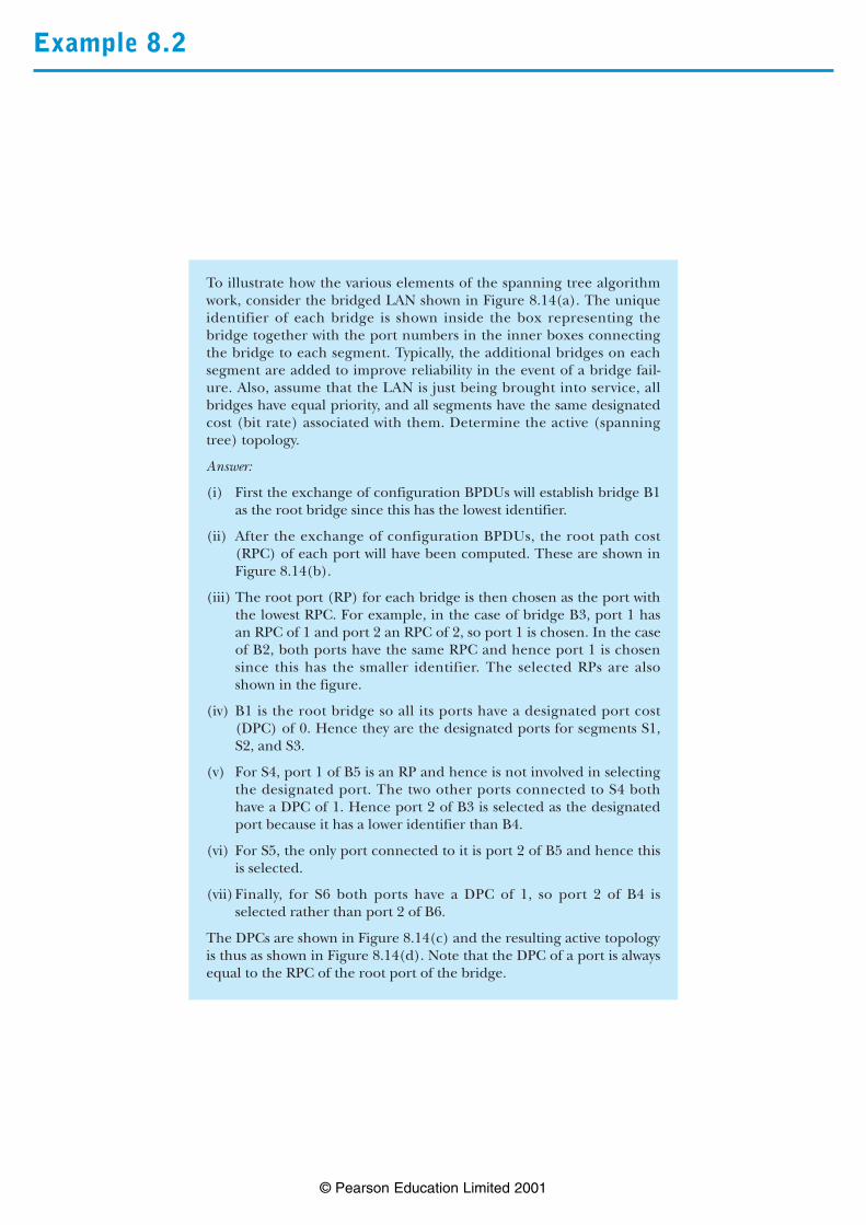
To illustrate how the various elements of the spanning tree algorithmwork, consider the bridged LAN shown in Figure 8.14(a). The uniqueidentifier of each bridge is shown inside the box representing thebridge together with the port numbers in the inner boxes connectingthe bridge to each segment. Typically, the additional bridges on eachsegment are added to improve reliability in the event of a bridge fail-ure. Also, assume that the LAN is just being brought into service, allbridges have equal priority, and all segments have the same designatedcost (bit rate) associated with them. Determine the active (spanningtree) topology.
Answer:
(i) First the exchange of configuration BPDUs will establish bridge B1as the root bridge since this has the lowest identifier.
(ii) After the exchange of configuration BPDUs, the root path cost(RPC) of each port will have been computed. These are shown inFigure 8.14(b).
(iii) The root port (RP) for each bridge is then chosen as the port withthe lowest RPC. For example, in the case of bridge B3, port 1 hasan RPC of 1 and port 2 an RPC of 2, so port 1 is chosen. In the caseof B2, both ports have the same RPC and hence port 1 is chosensince this has the smaller identifier. The selected RPs are alsoshown in the figure.
(iv) B1 is the root bridge so all its ports have a designated port cost(DPC) of 0. Hence they are the designated ports for segments S1,S2, and S3.
(v) For S4, port 1 of B5 is an RP and hence is not involved in selectingthe designated port. The two other ports connected to S4 bothhave a DPC of 1. Hence port 2 of B3 is selected as the designatedport because it has a lower identifier than B4.
(vi) For S5, the only port connected to it is port 2 of B5 and hence thisis selected.
(vii)Finally, for S6 both ports have a DPC of 1, so port 2 of B4 isselected rather than port 2 of B6.
The DPCs are shown in Figure 8.14(c) and the resulting active topologyis thus as shown in Figure 8.14(d). Note that the DPC of a port is alwaysequal to the RPC of the root port of the bridge.

Example 8.3
© Pearson Education Limited 2001
Assume the bridged LAN shown in Figure 8.17(a) is to operate usingsource routing. Also assume that all bridges have equal priority and allrings have the same designated cost (bit rate). Derive the followingwhen station A wishes to send a frame to station B:
(i) the active spanning tree for the LAN,
(ii) all the paths followed by the single-root broadcast frame(s),
(iii) all the paths followed by the all-routes broadcast frame(s),
(iv) the route (path) selected by A.
Answer:
(i) (a) Bridge B1 has the lowest identifier and is selected as the route.
(b) The root ports for each bridge are then derived as shown.
(c) The designated ports for each segment can now be derivedand these are as shown.
(d) The active topology is as shown in Figure 8.17(b).
(ii) Paths of single-route broadcast frames:
R1→B1→R2→B2→R3
R2→B3→R5→B6→R6
R1→B4→R4→B5
(iii)Paths of all-routes broadcast frames:
R6→B6→R5→B3→R2→B2→R3
B2→B1→R1
B1→B4→R4→B5→R5→B3
(iv) Since each ring has the same bit rate, the route (path) selected iseither:
R1→B1→R2→B3→R5→B6→R6
or
R1→B4→R4→B5→R5→B6→R6

Example 8.4
© Pearson Education Limited 2001
Assuming a signal propagation delay in the fiber of 5 µs per 1km, derivethe latency of the following FDDI ring configurations in both time andbits assuming a usable bit rate of 100Mbps.
(i) 2 km ring with 20 stations,
(ii) 20 km ring with 200 stations,
(iii) 100 km ring with 500 stations.
Answer:
Ring latency, Tl = Signal propagation delay, Tp + N × station latency,Ts where N is the number of stations.
(i) Tl = 2 × 5 + 20 × 1
= 30 µs or 3000 bits
(ii) Tl = 20 × 5 + 200 × 1
= 300 µs or 30000 bits
(iii) Tl = 100 × 5 + 500 × 1
= 1000 µs or 100000 bits
Note that the above values assume that the primary ring only is in use. Ifa fault occurred, the three signal propagation delay values would eachbe doubled. Also, for dual attach stations, the station latency would bedoubled.
Example 8.5
© Pearson Education Limited 2001
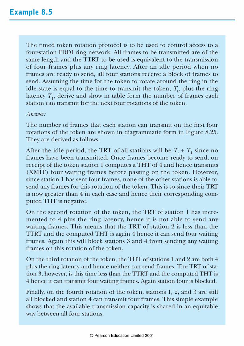
The timed token rotation protocol is to be used to control access to afour-station FDDI ring network. All frames to be transmitted are of thesame length and the TTRT to be used is equivalent to the transmissionof four frames plus any ring latency. After an idle period when noframes are ready to send, all four stations receive a block of frames tosend. Assuming the time for the token to rotate around the ring in theidle state is equal to the time to transmit the token, Tt, plus the ringlatency T1, derive and show in table form the number of frames eachstation can transmit for the next four rotations of the token.
Answer:
The number of frames that each station can transmit on the first fourrotations of the token are shown in diagrammatic form in Figure 8.25.They are derived as follows.
After the idle period, the TRT of all stations will be Tt + T1 since noframes have been transmitted. Once frames become ready to send, onreceipt of the token station 1 computes a THT of 4 and hence transmits(XMIT) four waiting frames before passing on the token. However,since station 1 has sent four frames, none of the other stations is able tosend any frames for this rotation of the token. This is so since their TRTis now greater than 4 in each case and hence their corresponding com-puted THT is negative.
On the second rotation of the token, the TRT of station 1 has incre-mented to 4 plus the ring latency, hence it is not able to send anywaiting frames. This means that the TRT of station 2 is less than theTTRT and the computed THT is again 4 hence it can send four waitingframes. Again this will block stations 3 and 4 from sending any waitingframes on this rotation of the token.
On the third rotation of the token, the THT of stations 1 and 2 are both 4plus the ring latency and hence neither can send frames. The TRT of sta-tion 3, however, is this time less than the TTRT and the computed THT is4 hence it can transmit four waiting frames. Again station four is blocked.
Finally, on the fourth rotation of the token, stations 1, 2, and 3 are stillall blocked and station 4 can transmit four frames. This simple exampleshows that the available transmission capacity is shared in an equitableway between all four stations.
Example 8.6
© Pearson Education Limited 2001
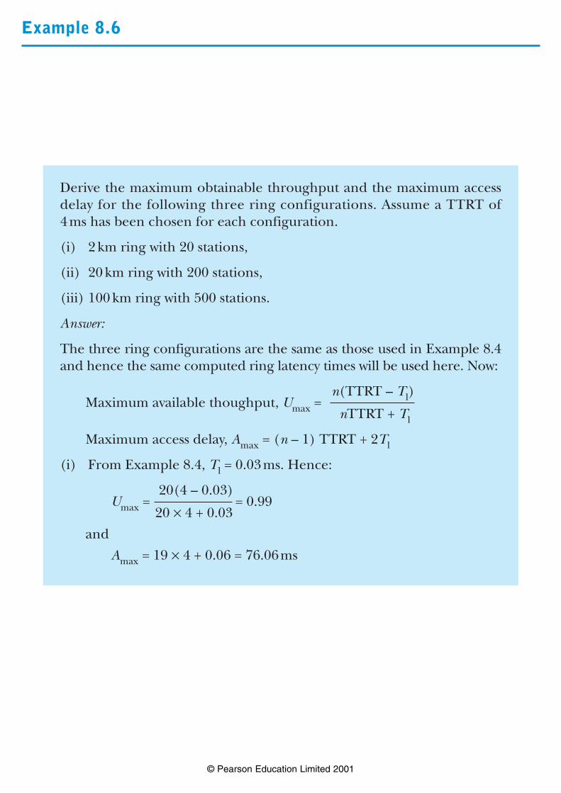
Derive the maximum obtainable throughput and the maximum accessdelay for the following three ring configurations. Assume a TTRT of4ms has been chosen for each configuration.
(i) 2km ring with 20 stations,
(ii) 20 km ring with 200 stations,
(iii) 100km ring with 500 stations.
Answer:
The three ring configurations are the same as those used in Example 8.4and hence the same computed ring latency times will be used here. Now:
n(TTRT – Tl)Maximum available thoughput, Umax =nTTRT + Tl
Maximum access delay, Amax = (n – 1) TTRT + 2Tl
(i) From Example 8.4, Tl = 0.03ms. Hence:
20(4 – 0.03)Umax = = 0.99
20 × 4 + 0.03
and
Amax = 19 × 4 + 0.06 = 76.06ms
8.6 Continued
© Pearson Education Limited 2001
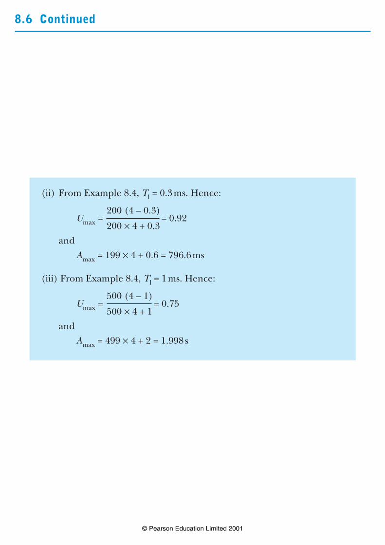
(ii) From Example 8.4, Tl = 0.3ms. Hence:
200 (4 – 0.3)Umax = = 0.92
200 × 4 + 0.3
and
Amax = 199 × 4 + 0.6 = 796.6ms
(iii) From Example 8.4, Tl = 1ms. Hence:
500 (4 – 1)Umax = = 0.75
500 × 4 + 1
and
Amax = 499 × 4 + 2 = 1.998s