figure 3 eon - static.highspeedbackbone.netstatic.highspeedbackbone.net/pdf/yyi1-t50395.pdf ·...
TRANSCRIPT

3. Push the panel mechanism back
into the housing so it is not protruding.
To do so, push the BOTTOM EDGE
down straight into the unit – do not
lift it! (Figure 7).
4. Immediately place the front panel
in its protective case for safe and
clean storage (Figure 8).
EON
EON
CONTENTS
MR1640W User’s Manual - page 1
U S E R ’ S M A N U A L
General and Tuner Controls
MR1640W User’s Manual - page 10 MR1640W User’s Manual - page 11
Wiring diagram
MR1640W User’s Manual - page 18
Troubleshooting
MR1640W User’s Manual - page 19
Specifications
MR1640W User’s Manual - page 20
MR1640W User’s Manual - page 4 MR1640W User’s Manual - page 5
Removing the head unit
Remote Control
MR1640W User’s Manual - page 14
General and Tuner Controls, continued
MR1640W User’s Manual - page 12 MR1640W User’s Manual - page 13
CD playback
MR1640W User’s Manual - page 15
MP3 disc playback
MR1640W User’s Manual - page 17
PTY Station Categories
MR1640W User’s Manual - page 6
Remote control installation
FLUSH MOUNT
MR1640W User’s Manual - page 7
Remote control installation, continued
MR1640W User’s Manual - page 16
RDS Radio functions
MR1640W User’s Manual - page 8
Remote control installation, continued
MR1640W User’s Manual - page 9
Remote control installation, continued
MR1640W User’s Manual - page 2
Head unit installation
MR2080W User’s Manual - page 3
Reinserting the front panelDetaching the front panel
MR1640 Marine MP3/CD Receiver Packing List
RESET button
Weather Band Tuning
Follow the wiring illustration below closely to obtain proper performance from your CDreceiver. Failure to make these connections properly may result in damage to your unitwhich will not be covered under your warranty.
This receiver contains a built-in high power four-channel amplifier. To use the built-inamplifier, connect the speaker wires as shown. To use the receiver as a head unit in a2CH, 4CH or 4CH-plus-subwoofer mobile audio system which includes an amplifier(s)or power subwoofer, use the RCA outputs to connect to the RCA inputs of your amplifier(s).
If you experience operation or performance problems with this product, compare yourinstallation with the electrical wiring diagram on the previous page. If problems persist,read the following troubleshooting tips which may help eliminate the problems.
Should you need to remove the head
unit, first remove and store the front
panel as described on the preceding
page.
After you have removed the front panel,
insert the removal keys supplied with
the head unit into the two removal slots
as shown in the drawing until you feel
a “click.” You can now use the levers
to pull the unit from the mounting
surface. (Figures 10 and 11).
Figure 11 Insert removal keys until “click” occurs,
keys to pull out head unit.
Please follow these general instructions toplay a music CD disc. On the column tothe right, you will find instructions for usingMP3 discs.
Please note that only some of thesefunctions are available on the remote control.
Loading a discPress down the latch on the disc door asshown in the figure below, and then pushit down to open the door.
Gently insert a disc into the disc slot untilyou feel it being drawn in by the playermechanism. If there is already a disc in theplayer, first press EJECT to eject it andremove it.
Playing a discThe disc will begin playing automatically. Ifyou wish to pause playback, pressPLAY/PAUSE, and press again to resumeplayback.
To start playback from the first track, pressPRESET 1. To select the next or last tentracks to play, press the +10 or -10 button.
Intro Scan functionThe Intro Scan function is a convenient wayto find a particular track. Press this buttonand the player will play the first few secondsof a song, and then skip to the next songand play a few seconds of that song. Thisprocess continues until you press the INTRObutton again, and the player will continueplaying that song.
Repeating a trackTo keep repeating the same track, pressthe REPEAT button. To cancel the repeatfunction, press again.
Random playPressing the RANDOM will cause the playerto play all the songs on the current disc inrandom order. Press again to cancel thisfunction.
When you insert an MP3 (or WMA) disc,the player will begin playback from the firsttrack in the directory.
However, MP3 discs can contain manymore tracks than audio CD’s, so you maywish to search for a particular track to play.There are three search methods available.
TRACK SEARCH MODE
In disc playback mode, press the BANDbutton once. The LCD will display the word“TRACK.”
To begin searching, press SELECT or theUP/DOWN button. Then press and holdthe UP or DOWN button to locate thedesired track, and press SELECT to beginplayback.
NAVIGATE THE CURRENT FOLDER
This mode permits you to navigate the filedirectory present on the disc.
To enter this mode, press BAND twice. Thedisplay will display “NAVIGA.” PressSELECT to enter this mode.
Use the UP and DOWN buttons to moveup and down the directory of folders andfiles on the disc. To enter a subfolder ,highlight it and press SELECT. You will thensee the directory of that subfolder and canselect tracks within it. So play a track,highlight it and push SELECT.
VIEWING MP3 FILE INFORMATION
Since many MP3 files are tagged withMusic/Artist/Album (ID3-TAG) information,you can see this as a list by pressing AS/PSrepeatedly.
The information will appear as a scrollingdisplay, including the folder and file nameas well as the ID3-TAG information.
Please note that if this information is notpresent in ID3-TAG version 1.0 or 2.0 format,it will not be displayed.
Push down on latch torelease it, then push it down toopen the door.
FRONT AUDIO OUTPUTSBROWN CABLEREAR AUDIO OUTPUTSGREY CABLE
RIGHT CH (RED)
LEFT CH (WHITE)
RIGHT CH (RED)
LEFT CH (WHITE)
ISO CONVERSIONCONNECTOR
OPTIONAL POWER AMPLIFIER
SPEAKER IMPEDANCE
MINIMUM 4 OHMS!
SPEAKER IMPEDANCE
MINIMUM 4 OHMS!
Place O-ring in groove on rear surface of flange of cup.
Follow these steps for a successful
installation:
1. Select the proper location which
accomodates the 3.45” overall
diameter, and mark its centerpoint.
2. Drill a hole with diameter of 3.2”-
3.3” (82-84mm). It is very important
that the hole does not exceed 3.3”.TA (Traffic Announcement)Many FM stations offer trafficannouncements in addition to their regularprogramming.
If you enable the TA function by pressingthe TA button, when this station broadcastsa traffic advisory, the radio’s RDS tuner willautomatically interrupt the regular programand play the alert. When the alert is finished,normal play of the broadcast will resume.
The TA function will also interrupt CD andMP3 playback temporarily if the EON featurehas been enabled (see below).
There are some other settings for TAbehavior that you can change. See theSELECT instructions on page 9 for moreinformation.
PTY (Program type)A number of RDS stations can be selectedby the type of program they broadcast, i.e.news, sport or classical music.
Press and hold the PTY button to cause thetuner to switch to RDS PTY type tuning. If atany time you wish to return to normal tuningmode, press and hold again.
When you have entered PTY mode, thedisplay will show “PTY” indicating that themode is enabled, and the name of the firstprogram type, “NEWS.”
To view other PTY categories, use theUP/DOWN buttons (a list of these categoriesis shown on the next page). To select thecategory, highlight it and press SELECT. Ifthere is no station found in that category, thedisplay will show “NONE PTY” and the radiowill return to normal mode.
3. Place the O-ring provided in the
groove on the rear surface of the flange
of the mounting cup.
4. Insert mounting arms fully into
mounting tube.
Mounting arms
Mounting tube
5. Insert mounting screws provided
through the slots in the cup and into
the threaded holes in the mounting
arms. Do not tighten more than a few
turns.
6. Insert this assembly fully into the
hole you have cut so that the flange
rests on the the mounting surface.
Be sure the cup is oriented with
arrow next to the word TOP is
pointing UP or your remote will be
turned when it is installed!
Insert the cup assembly fully into
the hole you have cut.
1. Place the mounting cup in the
location you wish to install it.
Using screws of suitable size and type
for your application, attach the cup to
the mounting surface. If necessary,
drill pilot holes for the screws first.
3. Press the cable into the curved
groove on the back of the remote
housing. Feed the cable end thru the
relief hole at the BACK of the cup OR
the bottom of the cup.
Be sure the cup is oriented with
arrow next to the word TOP is
pointing UP or your remote will be
turned when it is installed!
6. Grasp and turn the remote to the right
until it is in the correct position.
9. Press the cable into the curved
groove on the back of the remote
housing. Feed the cable end thru the
relief hole at the back of the cup.
10. Hold the remote in front of the cup
with the top up, and as you hold it, rotate
it about 20º counterclockwise.
11. Insert the remote control fully into the
cup so that the mounting hooks penetrate
the slots in the back of the cup.
If you feel resistance when you insert the
remote into the cup, pull the remote
housing and check that the cable has been
pressed into the curved slot, as described
in Step 2).
12. Grasp and turn the remote to the right
until it is in the correct position.
5. Insert the remote control fully into
the cup so that the mounting hooks
go through the slots in the back of the
cup.
If your installation is one in which the
cable is exiting out the bottom of the
housing (NOT the back), as you insert
the remote module pull the cable down
gently so it does not interfere with the
insertion of the remote into the cup.
4. Hold the remote in front of the cup
with the top up, and as you hold it,
rotate it about 20º counterclockwise.
2. If you are going to run the cable into
a hole in the mounting surface, drill a
hole of at least 9/16” (15mm) so that
you can pass the remote cable
connector through it.
If you are going to run the cable out
the bottom relief hole and out along
the mounting surface, skip this step.
If you feel resistance when you insert
the remote into the cup, pull the remote
housing out and check that the cable
has been pressed into the curved slot,
as described in Step 3).
To ensure that the installation
meets the IPX5 Waterproof
Standard, please follow these steps
carefully.
1. Remove the transport screws from
the top of the enclosure before
beginning the installation.
Fig 1 Remove transport screws
2. Place the two pieces of plastic film
provided over the two screw holes to
prevent water penetration.
Figure 2 Apply plastic film to seal screw holes
Figure 3 Bending the support tabs
Figure 9 Insert one end of the panel into the opening
in the main unit. Then push the other end of the
panel into main unit until you hear a “click”
1. Insert one side of the panel fully
into the opening in the main unit.
2. Then push the other end of the
front panel into the main body. You
should hear a “click.” (Figure 9)
NOTE: If the panel fails to lock into
position properly, the function of
some controls may be impaired,
and some segments of the display
may not become illuminated. If this
occurs, press RELEASE and reinstall
the front panel.
1. Press the RELEASE button to
release the panel from the right side
of the head unit (Figure 5).
2. Press the panel release latch on
the front edge of the lower surface of
faceplate, and at the same time pull
the panel forward to disengage it from
the main unit. (Figure 6).
Figure 5 Press RELEASE to release the front panel
RELEASE button
Figure 8 Place the front panel in its protective case
PUSH HERE in this direction
Figure 10 Slots for removal keys
Removal key slots
Before installing your new CD Receiver, please unpack the contents and check
that your package contains the following items:
RDS EON function settingThe RDS EON system extends thefunctionality of the TA sensing to a widerrange of traffic announcements from bothlocal and national sources. It also allows theunit to interrupt disc playback with theseannouncements. In addition, it will play theseannouncements (at normal listening level)even if the audio has been muted.
(To set this level, see instructions on page9 for setting V-PGM level).
To enable the EON function, press and holdthe SCAN button. Press again to disable it.
With EON enabled, when a trafficannouncement is broadcast, the radio willswitch automatically to TA mode, and “TP”(Traffic Program) will be displayed.
2 Head unit installation
4 Detaching the front panel
5 Removing the head unit
6 Remote control installationFlush mount
6 Remote control installationSurface mount
10 General and tuner controls
14 Remote control
15 CD Playback
15 MP3 playback
16 RDS radio functions
16 PTY station categories
17 Weather band tuning
18 Wiring diagram
19 Troubleshooting
20 Specifications
Congratulations on your
purchase of a Marine
Weather Band MP3/CD
Receiver.
It has been designed, engineered
and manufactured to bring you
the highest level of performance
and quality, and will afford you
years of listening pleasure.
Thank you for making
Marine your choice for
marine audio entertainment!
Main unitDetachable front panel with protective caseMounting hardware for main unit: Rear bracket plate Rear mounting screw Plain washer Spring washer Screw Hex nut Removal keys (2)Wiring harness
Wired remote controlRemote control cableMounting hardware for remote control: Mounting arms (2) Mounting tube (1) Machine screws (2)
User’s manualWarranty card
MR1640WFully MarinizedMP3-CompatibleIn-Dash CD Receiver
page
RDS EuropeanFrequency Model SYMPTOMCAUSEREMEDY
• Beep (when you press a button): ON/OFF
• Clock On (determines if clock will bedisplayed when radio is turned off):ON/OFF
• LCD1/2 (LCD brightness level): 1/2
RDS Radio Settings• SEEK/RDS ALLThis setting determines the behavior ofthe radio SEEK function when RDS tuningmode. If ALL is selected, the SEEKfunction will stop at both RDS and non-RDS stations. Otherwise, it will only seekRDS stations. RDS/ALL
• TA (Traffic Alert) SEEK/ALARMWhen TA mode is on, the radio monitorsthe Public Information channel which ispiggy-backed on the FM channel you arecurrently enjoying. If such a channel is notdetected or is weak the tuner will SEEKanother PI channel and monitor it.( Thisis the TA SEEK setting).
If ALARM setting is chosen, if a signal isinsufficiently strong, instead of monitoringan alternate station for PI information, theradio will produce a double beep (alarm)and silence itself, and display “LOST TPTA.” TA SEEK/ALARM
• TA VOLUMEThis setting determines the volume levelof the Traffic Alerts as they play.0-40 (18 is default)
• REG ON/OFFThis setting determines the behavior ofthe radio reception when AF (AlternateFrequency) mode is on. The AF systemcontinuously monitors the signal strengthof a station and compares it with otherstations on the same network. If anotherstation is stronger, it changes to thatstation.
Since sometimes in different regionsstations on the same network will playdifferent programs, the AF system caninterrupt the current program. If REG ONis selected, the station will check if theprograms are the same, and if not, the TAsystem will not change the station.REG OFF/ON
To turn on EON mode of RDS System,press and hold this button. When theEON function is turned on, “EON” willbe displayed on the screen (for moreinformation about the EON function seepage 16).
This list shows the PTY program types in theorder presented in the radio display:
NEWS
AFFAIRS
INFORMATION
SPORTS
EDUCATION
DRAMA
CULTURE
SCIENCE
VARIETY
POP MUSIC
ROCK MUSIC
EASY LISTENING MUSIC
LIGHT MUSIC
CLASSICAL MUSIC
OTHER MUSIC
WEATHER
FINANCE
CHILDREN
SOCIAL
RELIGIOUS
PHONE IN
TRAVEL
LEISURE
JAZZ MUSIC
COUNTRY MUSIC
NATIONAL MUSIC
OLDIES MUSIC
FOLK MUSIC
DOCUMENTARY
ALERT TEST
ALARM TEST
3. Insert and tighten the “headless”
support screw into the back of the
head unit where shown.
4. Insert the mounting case for the
head unit into the dashboard. Inspect
the dashboard material to determine
its approximate thickness. Select the
appropriate support tabs and bend
them outward to secure the bracket
in place (Figure 3).
5. Bend the backstrap to conform to
the mounting case and the dashboard
surface to which you plan to secure
the backstrap (Figure 4). Slide one of
the utility holes on the backstrap onto
the support screw and fasten it with
the spring washer and nut provided.
6. Using the 5 x 25mm screw and the
plain washer, secure the backstrap to
the dashboard surface as shown in
the diagram. Tighten, secure, and
check the overall mounting to be sure
it is safe and will not release in an
emergency stop or other sudden
movement of the vehicle.
Weather band listening is available usingTUNE/TRK buttons or the radio presets.
To hear the weather band stations, press theBAND button until the weather band isdisplayed.
The six preset buttons are assigned to thefollowing frequencies and cannot be changed:
PRESET #Frequency, MHz
1162.40
2162.43
3162.45
4162.47
5162.50
6162.53
if you wish to tune to the 7th available frequency,162.55MHz, use the TUNE/TRK buttons tolocate it.
Please note that in Weather Band, the followingbuttons are not operable:
SCANAS/PS
Mounting
surface
Drill a 9/16”
(15mm) or
larger hole to
allow cable to
pass through
mounting
surface.
Intallation with cable going
into hole in mounting surface.
Intallation with cable running out on top
of mounting surface.
Figure 6 Press release latch on on the lower surfaceof the front edge of the panel and pull the panel until it
is free of the head unit.
Figure 7 Push the panel mechanism back in
Slide the screws out to
extend the mounting arms
so that they reach behind
the mounting surface.
Insert the mounting screws through
the cup into the threaded holes
in the mounting arms
Hold the remote in front of
the cup, turned about
20º counterclockwise.
- OR -

3. Push the panel mechanism back
into the housing so it is not protruding.
To do so, push the BOTTOM EDGE
down straight into the unit – do not
lift it! (Figure 7).
4. Immediately place the front panel
in its protective case for safe and
clean storage (Figure 8).
EON
EON
CONTENTS
MR1640W User’s Manual - page 1
U S E R ’ S M A N U A L
General and Tuner Controls
MR1640W User’s Manual - page 10 MR1640W User’s Manual - page 11
Wiring diagram
MR1640W User’s Manual - page 18
Troubleshooting
MR1640W User’s Manual - page 19
Specifications
MR1640W User’s Manual - page 20
MR1640W User’s Manual - page 4 MR1640W User’s Manual - page 5
Removing the head unit
Remote Control
MR1640W User’s Manual - page 14
General and Tuner Controls, continued
MR1640W User’s Manual - page 12 MR1640W User’s Manual - page 13
CD playback
MR1640W User’s Manual - page 15
MP3 disc playback
MR1640W User’s Manual - page 17
PTY Station Categories
MR1640W User’s Manual - page 6
Remote control installation
FLUSH MOUNT
MR1640W User’s Manual - page 7
Remote control installation, continued
MR1640W User’s Manual - page 16
RDS Radio functions
MR1640W User’s Manual - page 8
Remote control installation, continued
MR1640W User’s Manual - page 9
Remote control installation, continued
MR1640W User’s Manual - page 2
Head unit installation
MR2080W User’s Manual - page 3
Reinserting the front panelDetaching the front panel
MR1640 Marine MP3/CD Receiver Packing List
RESET button
Weather Band Tuning
Follow the wiring illustration below closely to obtain proper performance from your CDreceiver. Failure to make these connections properly may result in damage to your unitwhich will not be covered under your warranty.
This receiver contains a built-in high power four-channel amplifier. To use the built-inamplifier, connect the speaker wires as shown. To use the receiver as a head unit in a2CH, 4CH or 4CH-plus-subwoofer mobile audio system which includes an amplifier(s)or power subwoofer, use the RCA outputs to connect to the RCA inputs of your amplifier(s).
If you experience operation or performance problems with this product, compare yourinstallation with the electrical wiring diagram on the previous page. If problems persist,read the following troubleshooting tips which may help eliminate the problems.
Should you need to remove the head
unit, first remove and store the front
panel as described on the preceding
page.
After you have removed the front panel,
insert the removal keys supplied with
the head unit into the two removal slots
as shown in the drawing until you feel
a “click.” You can now use the levers
to pull the unit from the mounting
surface. (Figures 10 and 11).
Figure 11 Insert removal keys until “click” occurs,
keys to pull out head unit.
Please follow these general instructions toplay a music CD disc. On the column tothe right, you will find instructions for usingMP3 discs.
Please note that only some of thesefunctions are available on the remote control.
Loading a discPress down the latch on the disc door asshown in the figure below, and then pushit down to open the door.
Gently insert a disc into the disc slot untilyou feel it being drawn in by the playermechanism. If there is already a disc in theplayer, first press EJECT to eject it andremove it.
Playing a discThe disc will begin playing automatically. Ifyou wish to pause playback, pressPLAY/PAUSE, and press again to resumeplayback.
To start playback from the first track, pressPRESET 1. To select the next or last tentracks to play, press the +10 or -10 button.
Intro Scan functionThe Intro Scan function is a convenient wayto find a particular track. Press this buttonand the player will play the first few secondsof a song, and then skip to the next songand play a few seconds of that song. Thisprocess continues until you press the INTRObutton again, and the player will continueplaying that song.
Repeating a trackTo keep repeating the same track, pressthe REPEAT button. To cancel the repeatfunction, press again.
Random playPressing the RANDOM will cause the playerto play all the songs on the current disc inrandom order. Press again to cancel thisfunction.
When you insert an MP3 (or WMA) disc,the player will begin playback from the firsttrack in the directory.
However, MP3 discs can contain manymore tracks than audio CD’s, so you maywish to search for a particular track to play.There are three search methods available.
TRACK SEARCH MODE
In disc playback mode, press the BANDbutton once. The LCD will display the word“TRACK.”
To begin searching, press SELECT or theUP/DOWN button. Then press and holdthe UP or DOWN button to locate thedesired track, and press SELECT to beginplayback.
NAVIGATE THE CURRENT FOLDER
This mode permits you to navigate the filedirectory present on the disc.
To enter this mode, press BAND twice. Thedisplay will display “NAVIGA.” PressSELECT to enter this mode.
Use the UP and DOWN buttons to moveup and down the directory of folders andfiles on the disc. To enter a subfolder ,highlight it and press SELECT. You will thensee the directory of that subfolder and canselect tracks within it. So play a track,highlight it and push SELECT.
VIEWING MP3 FILE INFORMATION
Since many MP3 files are tagged withMusic/Artist/Album (ID3-TAG) information,you can see this as a list by pressing AS/PSrepeatedly.
The information will appear as a scrollingdisplay, including the folder and file nameas well as the ID3-TAG information.
Please note that if this information is notpresent in ID3-TAG version 1.0 or 2.0 format,it will not be displayed.
Push down on latch torelease it, then push it down toopen the door.
FRONT AUDIO OUTPUTSBROWN CABLEREAR AUDIO OUTPUTSGREY CABLE
RIGHT CH (RED)
LEFT CH (WHITE)
RIGHT CH (RED)
LEFT CH (WHITE)
ISO CONVERSIONCONNECTOR
OPTIONAL POWER AMPLIFIER
SPEAKER IMPEDANCE
MINIMUM 4 OHMS!
SPEAKER IMPEDANCE
MINIMUM 4 OHMS!
Place O-ring in groove on rear surface of flange of cup.
Follow these steps for a successful
installation:
1. Select the proper location which
accomodates the 3.45” overall
diameter, and mark its centerpoint.
2. Drill a hole with diameter of 3.2”-
3.3” (82-84mm). It is very important
that the hole does not exceed 3.3”.TA (Traffic Announcement)Many FM stations offer trafficannouncements in addition to their regularprogramming.
If you enable the TA function by pressingthe TA button, when this station broadcastsa traffic advisory, the radio’s RDS tuner willautomatically interrupt the regular programand play the alert. When the alert is finished,normal play of the broadcast will resume.
The TA function will also interrupt CD andMP3 playback temporarily if the EON featurehas been enabled (see below).
There are some other settings for TAbehavior that you can change. See theSELECT instructions on page 9 for moreinformation.
PTY (Program type)A number of RDS stations can be selectedby the type of program they broadcast, i.e.news, sport or classical music.
Press and hold the PTY button to cause thetuner to switch to RDS PTY type tuning. If atany time you wish to return to normal tuningmode, press and hold again.
When you have entered PTY mode, thedisplay will show “PTY” indicating that themode is enabled, and the name of the firstprogram type, “NEWS.”
To view other PTY categories, use theUP/DOWN buttons (a list of these categoriesis shown on the next page). To select thecategory, highlight it and press SELECT. Ifthere is no station found in that category, thedisplay will show “NONE PTY” and the radiowill return to normal mode.
3. Place the O-ring provided in the
groove on the rear surface of the flange
of the mounting cup.
4. Insert mounting arms fully into
mounting tube.
Mounting arms
Mounting tube
5. Insert mounting screws provided
through the slots in the cup and into
the threaded holes in the mounting
arms. Do not tighten more than a few
turns.
6. Insert this assembly fully into the
hole you have cut so that the flange
rests on the the mounting surface.
Be sure the cup is oriented with
arrow next to the word TOP is
pointing UP or your remote will be
turned when it is installed!
Insert the cup assembly fully into
the hole you have cut.
1. Place the mounting cup in the
location you wish to install it.
Using screws of suitable size and type
for your application, attach the cup to
the mounting surface. If necessary,
drill pilot holes for the screws first.
3. Press the cable into the curved
groove on the back of the remote
housing. Feed the cable end thru the
relief hole at the BACK of the cup OR
the bottom of the cup.
Be sure the cup is oriented with
arrow next to the word TOP is
pointing UP or your remote will be
turned when it is installed!
6. Grasp and turn the remote to the right
until it is in the correct position.
9. Press the cable into the curved
groove on the back of the remote
housing. Feed the cable end thru the
relief hole at the back of the cup.
10. Hold the remote in front of the cup
with the top up, and as you hold it, rotate
it about 20º counterclockwise.
11. Insert the remote control fully into the
cup so that the mounting hooks penetrate
the slots in the back of the cup.
If you feel resistance when you insert the
remote into the cup, pull the remote
housing and check that the cable has been
pressed into the curved slot, as described
in Step 2).
12. Grasp and turn the remote to the right
until it is in the correct position.
5. Insert the remote control fully into
the cup so that the mounting hooks
go through the slots in the back of the
cup.
If your installation is one in which the
cable is exiting out the bottom of the
housing (NOT the back), as you insert
the remote module pull the cable down
gently so it does not interfere with the
insertion of the remote into the cup.
4. Hold the remote in front of the cup
with the top up, and as you hold it,
rotate it about 20º counterclockwise.
2. If you are going to run the cable into
a hole in the mounting surface, drill a
hole of at least 9/16” (15mm) so that
you can pass the remote cable
connector through it.
If you are going to run the cable out
the bottom relief hole and out along
the mounting surface, skip this step.
If you feel resistance when you insert
the remote into the cup, pull the remote
housing out and check that the cable
has been pressed into the curved slot,
as described in Step 3).
Before installing your new
CD Receiver, please become familiar
with all the information contained in
this manual.
Choose a mounting location where the
unit will not distract or otherwise
interfere with the pilot’s ability to control
the boat.
Use only the installation parts and
hardware provided with the unit to
ensure proper installation. Using other
parts can cause malfunction and
possible damage to your CD
receiver.
Do not install this unit at an angle in
excess of 30º from horizontal, as it
may affect performance.
Although this unit has been designed
for outdoor use, you can extend its life
if you install it in a location which is
not subject to extreme temperatures,
from such sources as heaters or
exhaust lines. Also, if you see dirt, dust
or debris on a disc or in the CD slot,
remove it with a clean cloth to avoid
pushing it into the player mechanism.
To remove dirt from the faceplate, use
a clean cloth lightly moistened with
filtered water. If the unit is splashed
with water, wipe it off with such a clean
damp cloth before the water has dried
to avoid an accumulation of salts on
the face of the unit.
If properly installed, this unit will meet
the IPX5 Waterproof standard. Please
note that this does NOT mean the unit
is submersible, but will resist being
sprayed and splashed as might occur
in a normal boat cabin.
To ensure that the installation
meets the IPX5 Waterproof
Standard, please follow these steps
carefully.
1. Remove the transport screws from
the top of the enclosure before
beginning the installation.
Fig 1 Remove transport screws
2. Place the two pieces of plastic film
provided over the two screw holes to
prevent water penetration.
Figure 2 Apply plastic film to seal screw holes
Figure 3 Bending the support tabs
Figure 9 Insert one end of the panel into the opening
in the main unit. Then push the other end of the
panel into main unit until you hear a “click”
1. Insert one side of the panel fully
into the opening in the main unit.
2. Then push the other end of the
front panel into the main body. You
should hear a “click.” (Figure 9)
NOTE: If the panel fails to lock into
position properly, the function of
some controls may be impaired,
and some segments of the display
may not become illuminated. If this
occurs, press RELEASE and reinstall
the front panel.
1. Press the RELEASE button to
release the panel from the right side
of the head unit (Figure 5).
2. Press the panel release latch on
the front edge of the lower surface of
faceplate, and at the same time pull
the panel forward to disengage it from
the main unit. (Figure 6).
Figure 5 Press RELEASE to release the front panel
RELEASE button
Figure 8 Place the front panel in its protective case
PUSH HERE in this direction
Figure 10 Slots for removal keys
Removal key slots
Before installing your new CD Receiver, please unpack the contents and check
that your package contains the following items:
RDS EON function settingThe RDS EON system extends thefunctionality of the TA sensing to a widerrange of traffic announcements from bothlocal and national sources. It also allows theunit to interrupt disc playback with theseannouncements. In addition, it will play theseannouncements (at normal listening level)even if the audio has been muted.
(To set this level, see instructions on page9 for setting V-PGM level).
To enable the EON function, press and holdthe SCAN button. Press again to disable it.
With EON enabled, when a trafficannouncement is broadcast, the radio willswitch automatically to TA mode, and “TP”(Traffic Program) will be displayed.
2 Head unit installation
4 Detaching the front panel
5 Removing the head unit
6 Remote control installationFlush mount
6 Remote control installationSurface mount
10 General and tuner controls
14 Remote control
15 CD Playback
15 MP3 playback
16 RDS radio functions
16 PTY station categories
17 Weather band tuning
18 Wiring diagram
19 Troubleshooting
20 Specifications
Congratulations on your
purchase of a Marine
Weather Band MP3/CD
Receiver.
It has been designed, engineered
and manufactured to bring you
the highest level of performance
and quality, and will afford you
years of listening pleasure.
Thank you for making
Marine your choice for
marine audio entertainment!
page
RDS EuropeanFrequency Model SYMPTOMCAUSEREMEDY
• Beep (when you press a button): ON/OFF
• Clock On (determines if clock will bedisplayed when radio is turned off):ON/OFF
• LCD1/2 (LCD brightness level): 1/2
RDS Radio Settings• SEEK/RDS ALLThis setting determines the behavior ofthe radio SEEK function when RDS tuningmode. If ALL is selected, the SEEKfunction will stop at both RDS and non-RDS stations. Otherwise, it will only seekRDS stations. RDS/ALL
• TA (Traffic Alert) SEEK/ALARMWhen TA mode is on, the radio monitorsthe Public Information channel which ispiggy-backed on the FM channel you arecurrently enjoying. If such a channel is notdetected or is weak the tuner will SEEKanother PI channel and monitor it.( Thisis the TA SEEK setting).
If ALARM setting is chosen, if a signal isinsufficiently strong, instead of monitoringan alternate station for PI information, theradio will produce a double beep (alarm)and silence itself, and display “LOST TPTA.” TA SEEK/ALARM
• TA VOLUMEThis setting determines the volume levelof the Traffic Alerts as they play.0-40 (18 is default)
• REG ON/OFFThis setting determines the behavior ofthe radio reception when AF (AlternateFrequency) mode is on. The AF systemcontinuously monitors the signal strengthof a station and compares it with otherstations on the same network. If anotherstation is stronger, it changes to thatstation.
Since sometimes in different regionsstations on the same network will playdifferent programs, the AF system caninterrupt the current program. If REG ONis selected, the station will check if theprograms are the same, and if not, the TAsystem will not change the station.REG OFF/ON
To turn on EON mode of RDS System,press and hold this button. When theEON function is turned on, “EON” willbe displayed on the screen (for moreinformation about the EON function seepage 16).
This list shows the PTY program types in theorder presented in the radio display:
NEWS
AFFAIRS
INFORMATION
SPORTS
EDUCATION
DRAMA
CULTURE
SCIENCE
VARIETY
POP MUSIC
ROCK MUSIC
EASY LISTENING MUSIC
LIGHT MUSIC
CLASSICAL MUSIC
OTHER MUSIC
WEATHER
FINANCE
CHILDREN
SOCIAL
RELIGIOUS
PHONE IN
TRAVEL
LEISURE
JAZZ MUSIC
COUNTRY MUSIC
NATIONAL MUSIC
OLDIES MUSIC
FOLK MUSIC
DOCUMENTARY
ALERT TEST
ALARM TEST
3. Insert and tighten the “headless”
support screw into the back of the
head unit where shown.
4. Insert the mounting case for the
head unit into the dashboard. Inspect
the dashboard material to determine
its approximate thickness. Select the
appropriate support tabs and bend
them outward to secure the bracket
in place (Figure 3).
5. Bend the backstrap to conform to
the mounting case and the dashboard
surface to which you plan to secure
the backstrap (Figure 4). Slide one of
the utility holes on the backstrap onto
the support screw and fasten it with
the spring washer and nut provided.
6. Using the 5 x 25mm screw and the
plain washer, secure the backstrap to
the dashboard surface as shown in
the diagram. Tighten, secure, and
check the overall mounting to be sure
it is safe and will not release in an
emergency stop or other sudden
movement of the vehicle.
Weather band listening is available usingTUNE/TRK buttons or the radio presets.
To hear the weather band stations, press theBAND button until the weather band isdisplayed.
The six preset buttons are assigned to thefollowing frequencies and cannot be changed:
PRESET #Frequency, MHz
1162.40
2162.43
3162.45
4162.47
5162.50
6162.53
if you wish to tune to the 7th available frequency,162.55MHz, use the TUNE/TRK buttons tolocate it.
Please note that in Weather Band, the followingbuttons are not operable:
SCANAS/PS
Mounting
surface
Drill a 9/16”
(15mm) or
larger hole to
allow cable to
pass through
mounting
surface.
Intallation with cable going
into hole in mounting surface.
Intallation with cable running out on top
of mounting surface.
Figure 6 Press release latch on on the lower surfaceof the front edge of the panel and pull the panel until itis free of the head unit.
Figure 7 Push the panel mechanism back in
Slide the screws out to
extend the mounting arms
so that they reach behind
the mounting surface.
Insert the mounting screws through
the cup into the threaded holes
in the mounting arms
Hold the remote in front of
the cup, turned about
20º counterclockwise.
- OR -

3. Push the panel mechanism back
into the housing so it is not protruding.
To do so, push the BOTTOM EDGE
down straight into the unit – do not
lift it! (Figure 7).
4. Immediately place the front panel
in its protective case for safe and
clean storage (Figure 8).
EON
EON
CONTENTS
MR1640W User’s Manual - page 1
U S E R ’ S M A N U A L
General and Tuner Controls
MR1640W User’s Manual - page 10 MR1640W User’s Manual - page 11
Wiring diagram
MR1640W User’s Manual - page 18
Troubleshooting
MR1640W User’s Manual - page 19
Specifications
MR1640W User’s Manual - page 20
MR1640W User’s Manual - page 4 MR1640W User’s Manual - page 5
Removing the head unit
Remote Control
MR1640W User’s Manual - page 14
General and Tuner Controls, continued
MR1640W User’s Manual - page 12 MR1640W User’s Manual - page 13
CD playback
MR1640W User’s Manual - page 15
MP3 disc playback
MR1640W User’s Manual - page 17
PTY Station Categories
MR1640W User’s Manual - page 6
Remote control installation
FLUSH MOUNT
MR1640W User’s Manual - page 7
Remote control installation, continued
MR1640W User’s Manual - page 16
RDS Radio functions
MR1640W User’s Manual - page 8
Remote control installation, continued
MR1640W User’s Manual - page 9
Remote control installation, continued
MR1640W User’s Manual - page 2
Head unit installation
MR2080W User’s Manual - page 3
Reinserting the front panelDetaching the front panel
MR1640 Marine MP3/CD Receiver Packing List
RESET button
Weather Band Tuning
Follow the wiring illustration below closely to obtain proper performance from your CDreceiver. Failure to make these connections properly may result in damage to your unitwhich will not be covered under your warranty.
This receiver contains a built-in high power four-channel amplifier. To use the built-inamplifier, connect the speaker wires as shown. To use the receiver as a head unit in a2CH, 4CH or 4CH-plus-subwoofer mobile audio system which includes an amplifier(s)or power subwoofer, use the RCA outputs to connect to the RCA inputs of your amplifier(s).
If you experience operation or performance problems with this product, compare yourinstallation with the electrical wiring diagram on the previous page. If problems persist,read the following troubleshooting tips which may help eliminate the problems.
Should you need to remove the head
unit, first remove and store the front
panel as described on the preceding
page.
After you have removed the front panel,
insert the removal keys supplied with
the head unit into the two removal slots
as shown in the drawing until you feel
a “click.” You can now use the levers
to pull the unit from the mounting
surface. (Figures 10 and 11).
Figure 11 Insert removal keys until “click” occurs,
keys to pull out head unit.
Please follow these general instructions toplay a music CD disc. On the column tothe right, you will find instructions for usingMP3 discs.
Please note that only some of thesefunctions are available on the remote control.
Loading a discPress down the latch on the disc door asshown in the figure below, and then pushit down to open the door.
Gently insert a disc into the disc slot untilyou feel it being drawn in by the playermechanism. If there is already a disc in theplayer, first press EJECT to eject it andremove it.
Playing a discThe disc will begin playing automatically. Ifyou wish to pause playback, pressPLAY/PAUSE, and press again to resumeplayback.
To start playback from the first track, pressPRESET 1. To select the next or last tentracks to play, press the +10 or -10 button.
Intro Scan functionThe Intro Scan function is a convenient wayto find a particular track. Press this buttonand the player will play the first few secondsof a song, and then skip to the next songand play a few seconds of that song. Thisprocess continues until you press the INTRObutton again, and the player will continueplaying that song.
Repeating a trackTo keep repeating the same track, pressthe REPEAT button. To cancel the repeatfunction, press again.
Random playPressing the RANDOM will cause the playerto play all the songs on the current disc inrandom order. Press again to cancel thisfunction.
When you insert an MP3 (or WMA) disc,the player will begin playback from the firsttrack in the directory.
However, MP3 discs can contain manymore tracks than audio CD’s, so you maywish to search for a particular track to play.There are three search methods available.
TRACK SEARCH MODE
In disc playback mode, press the BANDbutton once. The LCD will display the word“TRACK.”
To begin searching, press SELECT or theUP/DOWN button. Then press and holdthe UP or DOWN button to locate thedesired track, and press SELECT to beginplayback.
NAVIGATE THE CURRENT FOLDER
This mode permits you to navigate the filedirectory present on the disc.
To enter this mode, press BAND twice. Thedisplay will display “NAVIGA.” PressSELECT to enter this mode.
Use the UP and DOWN buttons to moveup and down the directory of folders andfiles on the disc. To enter a subfolder ,highlight it and press SELECT. You will thensee the directory of that subfolder and canselect tracks within it. So play a track,highlight it and push SELECT.
VIEWING MP3 FILE INFORMATION
Since many MP3 files are tagged withMusic/Artist/Album (ID3-TAG) information,you can see this as a list by pressing AS/PSrepeatedly.
The information will appear as a scrollingdisplay, including the folder and file nameas well as the ID3-TAG information.
Please note that if this information is notpresent in ID3-TAG version 1.0 or 2.0 format,it will not be displayed.
Push down on latch torelease it, then push it down toopen the door.
FRONT AUDIO OUTPUTSBROWN CABLEREAR AUDIO OUTPUTSGREY CABLE
RIGHT CH (RED)
LEFT CH (WHITE)
RIGHT CH (RED)
LEFT CH (WHITE)
ISO CONVERSIONCONNECTOR
OPTIONAL POWER AMPLIFIER
SPEAKER IMPEDANCE
MINIMUM 4 OHMS!
SPEAKER IMPEDANCE
MINIMUM 4 OHMS!
Place O-ring in groove on rear surface of flange of cup.
Follow these steps for a successful
installation:
1. Select the proper location which
accomodates the 3.45” overall
diameter, and mark its centerpoint.
2. Drill a hole with diameter of 3.2”-
3.3” (82-84mm). It is very important
that the hole does not exceed 3.3”.TA (Traffic Announcement)Many FM stations offer trafficannouncements in addition to their regularprogramming.
If you enable the TA function by pressingthe TA button, when this station broadcastsa traffic advisory, the radio’s RDS tuner willautomatically interrupt the regular programand play the alert. When the alert is finished,normal play of the broadcast will resume.
The TA function will also interrupt CD andMP3 playback temporarily if the EON featurehas been enabled (see below).
There are some other settings for TAbehavior that you can change. See theSELECT instructions on page 9 for moreinformation.
PTY (Program type)A number of RDS stations can be selectedby the type of program they broadcast, i.e.news, sport or classical music.
Press and hold the PTY button to cause thetuner to switch to RDS PTY type tuning. If atany time you wish to return to normal tuningmode, press and hold again.
When you have entered PTY mode, thedisplay will show “PTY” indicating that themode is enabled, and the name of the firstprogram type, “NEWS.”
To view other PTY categories, use theUP/DOWN buttons (a list of these categoriesis shown on the next page). To select thecategory, highlight it and press SELECT. Ifthere is no station found in that category, thedisplay will show “NONE PTY” and the radiowill return to normal mode.
3. Place the O-ring provided in the
groove on the rear surface of the flange
of the mounting cup.
4. Insert mounting arms fully into
mounting tube.
Mounting arms
Mounting tube
5. Insert mounting screws provided
through the slots in the cup and into
the threaded holes in the mounting
arms. Do not tighten more than a few
turns.
6. Insert this assembly fully into the
hole you have cut so that the flange
rests on the the mounting surface.
Be sure the cup is oriented with
arrow next to the word TOP is
pointing UP or your remote will be
turned when it is installed!
Insert the cup assembly fully into
the hole you have cut.
1. Place the mounting cup in the
location you wish to install it.
Using screws of suitable size and type
for your application, attach the cup to
the mounting surface. If necessary,
drill pilot holes for the screws first.
3. Press the cable into the curved
groove on the back of the remote
housing. Feed the cable end thru the
relief hole at the BACK of the cup OR
the bottom of the cup.
Be sure the cup is oriented with
arrow next to the word TOP is
pointing UP or your remote will be
turned when it is installed!
6. Grasp and turn the remote to the right
until it is in the correct position.
9. Press the cable into the curved
groove on the back of the remote
housing. Feed the cable end thru the
relief hole at the back of the cup.
10. Hold the remote in front of the cup
with the top up, and as you hold it, rotate
it about 20º counterclockwise.
11. Insert the remote control fully into the
cup so that the mounting hooks penetrate
the slots in the back of the cup.
If you feel resistance when you insert the
remote into the cup, pull the remote
housing and check that the cable has been
pressed into the curved slot, as described
in Step 2).
12. Grasp and turn the remote to the right
until it is in the correct position.
5. Insert the remote control fully into
the cup so that the mounting hooks
go through the slots in the back of the
cup.
If your installation is one in which the
cable is exiting out the bottom of the
housing (NOT the back), as you insert
the remote module pull the cable down
gently so it does not interfere with the
insertion of the remote into the cup.
4. Hold the remote in front of the cup
with the top up, and as you hold it,
rotate it about 20º counterclockwise.
2. If you are going to run the cable into
a hole in the mounting surface, drill a
hole of at least 9/16” (15mm) so that
you can pass the remote cable
connector through it.
If you are going to run the cable out
the bottom relief hole and out along
the mounting surface, skip this step.
If you feel resistance when you insert
the remote into the cup, pull the remote
housing out and check that the cable
has been pressed into the curved slot,
as described in Step 3).
To ensure that the installation
meets the IPX5 Waterproof
Standard, please follow these steps
carefully.
1. Remove the transport screws from
the top of the enclosure before
beginning the installation.
Fig 1 Remove transport screws
2. Place the two pieces of plastic film
provided over the two screw holes to
prevent water penetration.
Figure 2 Apply plastic film to seal screw holes
Figure 3 Bending the support tabs
Figure 4. Forming the support bracket
support strap
dashboard attachmentsurface
support screw
5 x 25mmsupport screw
plainwasher
springwasher
5mm nut
Figure 9 Insert one end of the panel into the opening
in the main unit. Then push the other end of the
panel into main unit until you hear a “click”
1. Insert one side of the panel fully
into the opening in the main unit.
2. Then push the other end of the
front panel into the main body. You
should hear a “click.” (Figure 9)
NOTE: If the panel fails to lock into
position properly, the function of
some controls may be impaired,
and some segments of the display
may not become illuminated. If this
occurs, press RELEASE and reinstall
the front panel.
1. Press the RELEASE button to
release the panel from the right side
of the head unit (Figure 5).
2. Press the panel release latch on
the front edge of the lower surface of
faceplate, and at the same time pull
the panel forward to disengage it from
the main unit. (Figure 6).
Figure 5 Press RELEASE to release the front panel
RELEASE button
Figure 8 Place the front panel in its protective case
PUSH HERE in this direction
Figure 10 Slots for removal keys
Removal key slots
Before installing your new CD Receiver, please unpack the contents and check
that your package contains the following items:
RDS EON function settingThe RDS EON system extends thefunctionality of the TA sensing to a widerrange of traffic announcements from bothlocal and national sources. It also allows theunit to interrupt disc playback with theseannouncements. In addition, it will play theseannouncements (at normal listening level)even if the audio has been muted.
(To set this level, see instructions on page9 for setting V-PGM level).
To enable the EON function, press and holdthe SCAN button. Press again to disable it.
With EON enabled, when a trafficannouncement is broadcast, the radio willswitch automatically to TA mode, and “TP”(Traffic Program) will be displayed.
2 Head unit installation
4 Detaching the front panel
5 Removing the head unit
6 Remote control installationFlush mount
6 Remote control installationSurface mount
10 General and tuner controls
14 Remote control
15 CD Playback
15 MP3 playback
16 RDS radio functions
16 PTY station categories
17 Weather band tuning
18 Wiring diagram
19 Troubleshooting
20 Specifications
Congratulations on your
purchase of a Marine
Weather Band MP3/CD
Receiver.
It has been designed, engineered
and manufactured to bring you
the highest level of performance
and quality, and will afford you
years of listening pleasure.
Thank you for making
Marine your choice for
marine audio entertainment!
page
RDS EuropeanFrequency Model support screw
head unit
mounting case
SYMPTOMCAUSEREMEDY
• Beep (when you press a button): ON/OFF
• Clock On (determines if clock will bedisplayed when radio is turned off):ON/OFF
• LCD1/2 (LCD brightness level): 1/2
RDS Radio Settings• SEEK/RDS ALLThis setting determines the behavior ofthe radio SEEK function when RDS tuningmode. If ALL is selected, the SEEKfunction will stop at both RDS and non-RDS stations. Otherwise, it will only seekRDS stations. RDS/ALL
• TA (Traffic Alert) SEEK/ALARMWhen TA mode is on, the radio monitorsthe Public Information channel which ispiggy-backed on the FM channel you arecurrently enjoying. If such a channel is notdetected or is weak the tuner will SEEKanother PI channel and monitor it.( Thisis the TA SEEK setting).
If ALARM setting is chosen, if a signal isinsufficiently strong, instead of monitoringan alternate station for PI information, theradio will produce a double beep (alarm)and silence itself, and display “LOST TPTA.” TA SEEK/ALARM
• TA VOLUMEThis setting determines the volume levelof the Traffic Alerts as they play.0-40 (18 is default)
• REG ON/OFFThis setting determines the behavior ofthe radio reception when AF (AlternateFrequency) mode is on. The AF systemcontinuously monitors the signal strengthof a station and compares it with otherstations on the same network. If anotherstation is stronger, it changes to thatstation.
Since sometimes in different regionsstations on the same network will playdifferent programs, the AF system caninterrupt the current program. If REG ONis selected, the station will check if theprograms are the same, and if not, the TAsystem will not change the station.REG OFF/ON
To turn on EON mode of RDS System,press and hold this button. When theEON function is turned on, “EON” willbe displayed on the screen (for moreinformation about the EON function seepage 16).
English Español Português Français DeutschEnglish Español Português Français Deutsch
This list shows the PTY program types in theorder presented in the radio display:
NEWS
AFFAIRS
INFORMATION
SPORTS
EDUCATION
DRAMA
CULTURE
SCIENCE
VARIETY
POP MUSIC
ROCK MUSIC
EASY LISTENING MUSIC
LIGHT MUSIC
CLASSICAL MUSIC
OTHER MUSIC
WEATHER
FINANCE
CHILDREN
SOCIAL
RELIGIOUS
PHONE IN
TRAVEL
LEISURE
JAZZ MUSIC
COUNTRY MUSIC
NATIONAL MUSIC
OLDIES MUSIC
FOLK MUSIC
DOCUMENTARY
ALERT TEST
ALARM TEST
3. Insert and tighten the “headless”
support screw into the back of the
head unit where shown.
4. Insert the mounting case for the
head unit into the dashboard. Inspect
the dashboard material to determine
its approximate thickness. Select the
appropriate support tabs and bend
them outward to secure the bracket
in place (Figure 3).
5. Bend the backstrap to conform to
the mounting case and the dashboard
surface to which you plan to secure
the backstrap (Figure 4). Slide one of
the utility holes on the backstrap onto
the support screw and fasten it with
the spring washer and nut provided.
6. Using the 5 x 25mm screw and the
plain washer, secure the backstrap to
the dashboard surface as shown in
the diagram. Tighten, secure, and
check the overall mounting to be sure
it is safe and will not release in an
emergency stop or other sudden
movement of the vehicle.
Weather band listening is available usingTUNE/TRK buttons or the radio presets.
To hear the weather band stations, press theBAND button until the weather band isdisplayed.
The six preset buttons are assigned to thefollowing frequencies and cannot be changed:
PRESET #Frequency, MHz
1162.40
2162.43
3162.45
4162.47
5162.50
6162.53
if you wish to tune to the 7th available frequency,162.55MHz, use the TUNE/TRK buttons tolocate it.
Please note that in Weather Band, the followingbuttons are not operable:
SCANAS/PS
Mounting
surface
Drill a 9/16”
(15mm) or
larger hole to
allow cable to
pass through
mounting
surface.
Intallation with cable going
into hole in mounting surface.
Intallation with cable running out on top
of mounting surface.
Figure 6 Press release latch on on the lower surfaceof the front edge of the panel and pull the panel until it
is free of the head unit.
Figure 7 Push the panel mechanism back in
Slide the screws out to
extend the mounting arms
so that they reach behind
the mounting surface.
Insert the mounting screws through
the cup into the threaded holes
in the mounting arms
Hold the remote in front of
the cup, turned about
20º counterclockwise.
- OR -

3. Push the panel mechanism back
into the housing so it is not protruding.
To do so, push the BOTTOM EDGE
down straight into the unit – do not
lift it! (Figure 7).
4. Immediately place the front panel
in its protective case for safe and
clean storage (Figure 8).
EON
EON
CONTENTS
MR1640W User’s Manual - page 1
U S E R ’ S M A N U A L
General and Tuner Controls
MR1640W User’s Manual - page 10 MR1640W User’s Manual - page 11
Wiring diagram
MR1640W User’s Manual - page 18
Troubleshooting
MR1640W User’s Manual - page 19
Specifications
MR1640W User’s Manual - page 20
MR1640W User’s Manual - page 4 MR1640W User’s Manual - page 5
Removing the head unit
Remote Control
MR1640W User’s Manual - page 14
General and Tuner Controls, continued
MR1640W User’s Manual - page 12 MR1640W User’s Manual - page 13
CD playback
MR1640W User’s Manual - page 15
MP3 disc playback
MR1640W User’s Manual - page 17
PTY Station Categories
MR1640W User’s Manual - page 6
Remote control installation
FLUSH MOUNT
MR1640W User’s Manual - page 7
Remote control installation, continued
MR1640W User’s Manual - page 16
RDS Radio functions
MR1640W User’s Manual - page 8
Remote control installation, continued
MR1640W User’s Manual - page 9
Remote control installation, continued
MR1640W User’s Manual - page 2
Head unit installation
MR2080W User’s Manual - page 3
Reinserting the front panelDetaching the front panel
MR1640 Marine MP3/CD Receiver Packing List
RESET button
Weather Band Tuning
Follow the wiring illustration below closely to obtain proper performance from your CDreceiver. Failure to make these connections properly may result in damage to your unitwhich will not be covered under your warranty.
This receiver contains a built-in high power four-channel amplifier. To use the built-inamplifier, connect the speaker wires as shown. To use the receiver as a head unit in a2CH, 4CH or 4CH-plus-subwoofer mobile audio system which includes an amplifier(s)or power subwoofer, use the RCA outputs to connect to the RCA inputs of your amplifier(s).
If you experience operation or performance problems with this product, compare yourinstallation with the electrical wiring diagram on the previous page. If problems persist,read the following troubleshooting tips which may help eliminate the problems.
Be careful when handling the front panel!
1. Do not drop front panel.
2. When detaching or reinstalling, do not put pressure on the display.
3. Do not touch the contacts on the panel or the main unit body – doing so may result in poor electrical contact.
4. Dirt or foreign substances can be removed with a clean, dry cloth.
5. Do not expose the panel to high temperaturees or direct sunlight.
6. Do not permit volatile agents or solvents to contact the front panel.
7. Do not attempt to disassemble the front panel.
Should you need to remove the head
unit, first remove and store the front
panel as described on the preceding
page.
After you have removed the front panel,
insert the removal keys supplied with
the head unit into the two removal slots
as shown in the drawing until you feel
a “click.” You can now use the levers
to pull the unit from the mounting
surface. (Figures 10 and 11).
Figure 11 Insert removal keys until “click” occurs,
keys to pull out head unit.
Please follow these general instructions toplay a music CD disc. On the column tothe right, you will find instructions for usingMP3 discs.
Please note that only some of thesefunctions are available on the remote control.
Loading a discPress down the latch on the disc door asshown in the figure below, and then pushit down to open the door.
Gently insert a disc into the disc slot untilyou feel it being drawn in by the playermechanism. If there is already a disc in theplayer, first press EJECT to eject it andremove it.
Playing a discThe disc will begin playing automatically. Ifyou wish to pause playback, pressPLAY/PAUSE, and press again to resumeplayback.
To start playback from the first track, pressPRESET 1. To select the next or last tentracks to play, press the +10 or -10 button.
Intro Scan functionThe Intro Scan function is a convenient wayto find a particular track. Press this buttonand the player will play the first few secondsof a song, and then skip to the next songand play a few seconds of that song. Thisprocess continues until you press the INTRObutton again, and the player will continueplaying that song.
Repeating a trackTo keep repeating the same track, pressthe REPEAT button. To cancel the repeatfunction, press again.
Random playPressing the RANDOM will cause the playerto play all the songs on the current disc inrandom order. Press again to cancel thisfunction.
When you insert an MP3 (or WMA) disc,the player will begin playback from the firsttrack in the directory.
However, MP3 discs can contain manymore tracks than audio CD’s, so you maywish to search for a particular track to play.There are three search methods available.
TRACK SEARCH MODE
In disc playback mode, press the BANDbutton once. The LCD will display the word“TRACK.”
To begin searching, press SELECT or theUP/DOWN button. Then press and holdthe UP or DOWN button to locate thedesired track, and press SELECT to beginplayback.
NAVIGATE THE CURRENT FOLDER
This mode permits you to navigate the filedirectory present on the disc.
To enter this mode, press BAND twice. Thedisplay will display “NAVIGA.” PressSELECT to enter this mode.
Use the UP and DOWN buttons to moveup and down the directory of folders andfiles on the disc. To enter a subfolder ,highlight it and press SELECT. You will thensee the directory of that subfolder and canselect tracks within it. So play a track,highlight it and push SELECT.
VIEWING MP3 FILE INFORMATION
Since many MP3 files are tagged withMusic/Artist/Album (ID3-TAG) information,you can see this as a list by pressing AS/PSrepeatedly.
The information will appear as a scrollingdisplay, including the folder and file nameas well as the ID3-TAG information.
Please note that if this information is notpresent in ID3-TAG version 1.0 or 2.0 format,it will not be displayed.
Push down on latch torelease it, then push it down toopen the door.
FRONT AUDIO OUTPUTSBROWN CABLE
REAR AUDIO OUTPUTSGREY CABLE
RIGHT CH (RED)
LEFT CH (WHITE)
RIGHT CH (RED)
LEFT CH (WHITE)
ISO CONVERSIONCONNECTOR
OPTIONAL POWER AMPLIFIER
SPEAKER IMPEDANCE
MINIMUM 4 OHMS!
SPEAKER IMPEDANCE
MINIMUM 4 OHMS!
Place O-ring in groove on rear surface of flange of cup.
Follow these steps for a successful
installation:
1. Select the proper location which
accomodates the 3.45” overall
diameter, and mark its centerpoint.
2. Drill a hole with diameter of 3.2”-
3.3” (82-84mm). It is very important
that the hole does not exceed 3.3”.TA (Traffic Announcement)Many FM stations offer trafficannouncements in addition to their regularprogramming.
If you enable the TA function by pressingthe TA button, when this station broadcastsa traffic advisory, the radio’s RDS tuner willautomatically interrupt the regular programand play the alert. When the alert is finished,normal play of the broadcast will resume.
The TA function will also interrupt CD andMP3 playback temporarily if the EON featurehas been enabled (see below).
There are some other settings for TAbehavior that you can change. See theSELECT instructions on page 9 for moreinformation.
PTY (Program type)A number of RDS stations can be selectedby the type of program they broadcast, i.e.news, sport or classical music.
Press and hold the PTY button to cause thetuner to switch to RDS PTY type tuning. If atany time you wish to return to normal tuningmode, press and hold again.
When you have entered PTY mode, thedisplay will show “PTY” indicating that themode is enabled, and the name of the firstprogram type, “NEWS.”
To view other PTY categories, use theUP/DOWN buttons (a list of these categoriesis shown on the next page). To select thecategory, highlight it and press SELECT. Ifthere is no station found in that category, thedisplay will show “NONE PTY” and the radiowill return to normal mode.
3. Place the O-ring provided in the
groove on the rear surface of the flange
of the mounting cup.
4. Insert mounting arms fully into
mounting tube.
Mounting arms
Mounting tube
5. Insert mounting screws provided
through the slots in the cup and into
the threaded holes in the mounting
arms. Do not tighten more than a few
turns.
6. Insert this assembly fully into the
hole you have cut so that the flange
rests on the the mounting surface.
Be sure the cup is oriented with
arrow next to the word TOP is
pointing UP or your remote will be
turned when it is installed!
Insert the cup assembly fully into
the hole you have cut.
1. Place the mounting cup in the
location you wish to install it.
Using screws of suitable size and type
for your application, attach the cup to
the mounting surface. If necessary,
drill pilot holes for the screws first.
3. Press the cable into the curved
groove on the back of the remote
housing. Feed the cable end thru the
relief hole at the BACK of the cup OR
the bottom of the cup.
Be sure the cup is oriented with
arrow next to the word TOP is
pointing UP or your remote will be
turned when it is installed!
6. Grasp and turn the remote to the right
until it is in the correct position.
9. Press the cable into the curved
groove on the back of the remote
housing. Feed the cable end thru the
relief hole at the back of the cup.
10. Hold the remote in front of the cup
with the top up, and as you hold it, rotate
it about 20º counterclockwise.
11. Insert the remote control fully into the
cup so that the mounting hooks penetrate
the slots in the back of the cup.
If you feel resistance when you insert the
remote into the cup, pull the remote
housing and check that the cable has been
pressed into the curved slot, as described
in Step 2).
12. Grasp and turn the remote to the right
until it is in the correct position.
5. Insert the remote control fully into
the cup so that the mounting hooks
go through the slots in the back of the
cup.
If your installation is one in which the
cable is exiting out the bottom of the
housing (NOT the back), as you insert
the remote module pull the cable down
gently so it does not interfere with the
insertion of the remote into the cup.
4. Hold the remote in front of the cup
with the top up, and as you hold it,
rotate it about 20º counterclockwise.
2. If you are going to run the cable into
a hole in the mounting surface, drill a
hole of at least 9/16” (15mm) so that
you can pass the remote cable
connector through it.
If you are going to run the cable out
the bottom relief hole and out along
the mounting surface, skip this step.
If you feel resistance when you insert
the remote into the cup, pull the remote
housing out and check that the cable
has been pressed into the curved slot,
as described in Step 3).
To ensure that the installation
meets the IPX5 Waterproof
Standard, please follow these steps
carefully.
1. Remove the transport screws from
the top of the enclosure before
beginning the installation.
Fig 1 Remove transport screws
2. Place the two pieces of plastic film
provided over the two screw holes to
prevent water penetration.
Figure 2 Apply plastic film to seal screw holes
Figure 3 Bending the support tabs
Figure 9 Insert one end of the panel into the opening
in the main unit. Then push the other end of the
panel into main unit until you hear a “click”
1. Insert one side of the panel fully
into the opening in the main unit.
2. Then push the other end of the
front panel into the main body. You
should hear a “click.” (Figure 9)
NOTE: If the panel fails to lock into
position properly, the function of
some controls may be impaired,
and some segments of the display
may not become illuminated. If this
occurs, press RELEASE and reinstall
the front panel.
1. Press the RELEASE button to
release the panel from the right side
of the head unit (Figure 5).
2. Press the panel release latch on
the front edge of the lower surface of
faceplate, and at the same time pull
the panel forward to disengage it from
the main unit. (Figure 6).
Figure 5 Press RELEASE to release the front panel
RELEASE button
Front Panel
Figure 8 Place the front panel in its protective case
PUSH HERE in this direction
Figure 10 Slots for removal keys
Removal key slots
Before installing your new CD Receiver, please unpack the contents and check
that your package contains the following items:
RDS EON function settingThe RDS EON system extends thefunctionality of the TA sensing to a widerrange of traffic announcements from bothlocal and national sources. It also allows theunit to interrupt disc playback with theseannouncements. In addition, it will play theseannouncements (at normal listening level)even if the audio has been muted.
(To set this level, see instructions on page9 for setting V-PGM level).
To enable the EON function, press and holdthe SCAN button. Press again to disable it.
With EON enabled, when a trafficannouncement is broadcast, the radio willswitch automatically to TA mode, and “TP”(Traffic Program) will be displayed.
2 Head unit installation
4 Detaching the front panel
5 Removing the head unit
6 Remote control installationFlush mount
6 Remote control installationSurface mount
10 General and tuner controls
14 Remote control
15 CD Playback
15 MP3 playback
16 RDS radio functions
16 PTY station categories
17 Weather band tuning
18 Wiring diagram
19 Troubleshooting
20 Specifications
Congratulations on your
purchase of a Marine
Weather Band MP3/CD
Receiver.
It has been designed, engineered
and manufactured to bring you
the highest level of performance
and quality, and will afford you
years of listening pleasure.
Thank you for making
Marine your choice for
marine audio entertainment!
page
RDS EuropeanFrequency Model SYMPTOMCAUSEREMEDY
• Beep (when you press a button): ON/OFF
• Clock On (determines if clock will bedisplayed when radio is turned off):ON/OFF
• LCD1/2 (LCD brightness level): 1/2
RDS Radio Settings• SEEK/RDS ALLThis setting determines the behavior ofthe radio SEEK function when RDS tuningmode. If ALL is selected, the SEEKfunction will stop at both RDS and non-RDS stations. Otherwise, it will only seekRDS stations. RDS/ALL
• TA (Traffic Alert) SEEK/ALARMWhen TA mode is on, the radio monitorsthe Public Information channel which ispiggy-backed on the FM channel you arecurrently enjoying. If such a channel is notdetected or is weak the tuner will SEEKanother PI channel and monitor it.( Thisis the TA SEEK setting).
If ALARM setting is chosen, if a signal isinsufficiently strong, instead of monitoringan alternate station for PI information, theradio will produce a double beep (alarm)and silence itself, and display “LOST TPTA.” TA SEEK/ALARM
• TA VOLUMEThis setting determines the volume levelof the Traffic Alerts as they play.0-40 (18 is default)
• REG ON/OFFThis setting determines the behavior ofthe radio reception when AF (AlternateFrequency) mode is on. The AF systemcontinuously monitors the signal strengthof a station and compares it with otherstations on the same network. If anotherstation is stronger, it changes to thatstation.
Since sometimes in different regionsstations on the same network will playdifferent programs, the AF system caninterrupt the current program. If REG ONis selected, the station will check if theprograms are the same, and if not, the TAsystem will not change the station.REG OFF/ON
To turn on EON mode of RDS System,press and hold this button. When theEON function is turned on, “EON” willbe displayed on the screen (for moreinformation about the EON function seepage 16).
This list shows the PTY program types in theorder presented in the radio display:
NEWS
AFFAIRS
INFORMATION
SPORTS
EDUCATION
DRAMA
CULTURE
SCIENCE
VARIETY
POP MUSIC
ROCK MUSIC
EASY LISTENING MUSIC
LIGHT MUSIC
CLASSICAL MUSIC
OTHER MUSIC
WEATHER
FINANCE
CHILDREN
SOCIAL
RELIGIOUS
PHONE IN
TRAVEL
LEISURE
JAZZ MUSIC
COUNTRY MUSIC
NATIONAL MUSIC
OLDIES MUSIC
FOLK MUSIC
DOCUMENTARY
ALERT TEST
ALARM TEST
3. Insert and tighten the “headless”
support screw into the back of the
head unit where shown.
4. Insert the mounting case for the
head unit into the dashboard. Inspect
the dashboard material to determine
its approximate thickness. Select the
appropriate support tabs and bend
them outward to secure the bracket
in place (Figure 3).
5. Bend the backstrap to conform to
the mounting case and the dashboard
surface to which you plan to secure
the backstrap (Figure 4). Slide one of
the utility holes on the backstrap onto
the support screw and fasten it with
the spring washer and nut provided.
6. Using the 5 x 25mm screw and the
plain washer, secure the backstrap to
the dashboard surface as shown in
the diagram. Tighten, secure, and
check the overall mounting to be sure
it is safe and will not release in an
emergency stop or other sudden
movement of the vehicle.
Weather band listening is available usingTUNE/TRK buttons or the radio presets.
To hear the weather band stations, press theBAND button until the weather band isdisplayed.
The six preset buttons are assigned to thefollowing frequencies and cannot be changed:
PRESET # Frequency, MHz
1 162.40
2 162.43
3 162.45
4 162.47
5 162.50
6 162.53
if you wish to tune to the 7th available frequency,162.55MHz, use the TUNE/TRK buttons tolocate it.
Please note that in Weather Band, the followingbuttons are not operable:
SCANAS/PS
Mounting
surface
Drill a 9/16”
(15mm) or
larger hole to
allow cable to
pass through
mounting
surface.
Intallation with cable going
into hole in mounting surface.
Intallation with cable running out on top
of mounting surface.
Figure 6 Press release latch on on the lower surfaceof the front edge of the panel and pull the panel until itis free of the head unit.
Figure 7 Push the panel mechanism back in
Slide the screws out to
extend the mounting arms
so that they reach behind
the mounting surface.
Insert the mounting screws through
the cup into the threaded holes
in the mounting arms
Hold the remote in front of
the cup, turned about
20º counterclockwise.
- OR -

3. Push the panel mechanism back
into the housing so it is not protruding.
To do so, push the BOTTOM EDGE
down straight into the unit – do not
lift it! (Figure 7).
4. Immediately place the front panel
in its protective case for safe and
clean storage (Figure 8).
EON
EON
CONTENTS
MR1640W User’s Manual - page 1
U S E R ’ S M A N U A L
General and Tuner Controls
MR1640W User’s Manual - page 10 MR1640W User’s Manual - page 11
Wiring diagram
MR1640W User’s Manual - page 18
Troubleshooting
MR1640W User’s Manual - page 19
Specifications
MR1640W User’s Manual - page 20
MR1640W User’s Manual - page 4 MR1640W User’s Manual - page 5
Removing the head unit
Remote Control
MR1640W User’s Manual - page 14
General and Tuner Controls, continued
MR1640W User’s Manual - page 12 MR1640W User’s Manual - page 13
CD playback
MR1640W User’s Manual - page 15
MP3 disc playback
MR1640W User’s Manual - page 17
PTY Station Categories
MR1640W User’s Manual - page 6
Remote control installation
FLUSH MOUNT
MR1640W User’s Manual - page 7
Remote control installation, continued
MR1640W User’s Manual - page 16
RDS Radio functions
MR1640W User’s Manual - page 8
Remote control installation, continued
MR1640W User’s Manual - page 9
Remote control installation, continued
MR1640W User’s Manual - page 2
Head unit installation
MR2080W User’s Manual - page 3
Reinserting the front panelDetaching the front panel
MR1640 Marine MP3/CD Receiver Packing List
RESET button
Weather Band Tuning
Follow the wiring illustration below closely to obtain proper performance from your CDreceiver. Failure to make these connections properly may result in damage to your unitwhich will not be covered under your warranty.
This receiver contains a built-in high power four-channel amplifier. To use the built-inamplifier, connect the speaker wires as shown. To use the receiver as a head unit in a2CH, 4CH or 4CH-plus-subwoofer mobile audio system which includes an amplifier(s)or power subwoofer, use the RCA outputs to connect to the RCA inputs of your amplifier(s).
If you experience operation or performance problems with this product, compare yourinstallation with the electrical wiring diagram on the previous page. If problems persist,read the following troubleshooting tips which may help eliminate the problems.
Should you need to remove the head
unit, first remove and store the front
panel as described on the preceding
page.
After you have removed the front panel,
insert the removal keys supplied with
the head unit into the two removal slots
as shown in the drawing until you feel
a “click.” You can now use the levers
to pull the unit from the mounting
surface. (Figures 10 and 11).
Figure 11 Insert removal keys until “click” occurs,
keys to pull out head unit.
Please follow these general instructions toplay a music CD disc. On the column tothe right, you will find instructions for usingMP3 discs.
Please note that only some of thesefunctions are available on the remote control.
Loading a discPress down the latch on the disc door asshown in the figure below, and then pushit down to open the door.
Gently insert a disc into the disc slot untilyou feel it being drawn in by the playermechanism. If there is already a disc in theplayer, first press EJECT to eject it andremove it.
Playing a discThe disc will begin playing automatically. Ifyou wish to pause playback, pressPLAY/PAUSE, and press again to resumeplayback.
To start playback from the first track, pressPRESET 1. To select the next or last tentracks to play, press the +10 or -10 button.
Intro Scan functionThe Intro Scan function is a convenient wayto find a particular track. Press this buttonand the player will play the first few secondsof a song, and then skip to the next songand play a few seconds of that song. Thisprocess continues until you press the INTRObutton again, and the player will continueplaying that song.
Repeating a trackTo keep repeating the same track, pressthe REPEAT button. To cancel the repeatfunction, press again.
Random playPressing the RANDOM will cause the playerto play all the songs on the current disc inrandom order. Press again to cancel thisfunction.
When you insert an MP3 (or WMA) disc,the player will begin playback from the firsttrack in the directory.
However, MP3 discs can contain manymore tracks than audio CD’s, so you maywish to search for a particular track to play.There are three search methods available.
TRACK SEARCH MODE
In disc playback mode, press the BANDbutton once. The LCD will display the word“TRACK.”
To begin searching, press SELECT or theUP/DOWN button. Then press and holdthe UP or DOWN button to locate thedesired track, and press SELECT to beginplayback.
NAVIGATE THE CURRENT FOLDER
This mode permits you to navigate the filedirectory present on the disc.
To enter this mode, press BAND twice. Thedisplay will display “NAVIGA.” PressSELECT to enter this mode.
Use the UP and DOWN buttons to moveup and down the directory of folders andfiles on the disc. To enter a subfolder ,highlight it and press SELECT. You will thensee the directory of that subfolder and canselect tracks within it. So play a track,highlight it and push SELECT.
VIEWING MP3 FILE INFORMATION
Since many MP3 files are tagged withMusic/Artist/Album (ID3-TAG) information,you can see this as a list by pressing AS/PSrepeatedly.
The information will appear as a scrollingdisplay, including the folder and file nameas well as the ID3-TAG information.
Please note that if this information is notpresent in ID3-TAG version 1.0 or 2.0 format,it will not be displayed.
Push down on latch torelease it, then push it down toopen the door.
FRONT AUDIO OUTPUTSBROWN CABLE
REAR AUDIO OUTPUTSGREY CABLE
RIGHT CH (RED)
LEFT CH (WHITE)
RIGHT CH (RED)
LEFT CH (WHITE)
ISO CONVERSIONCONNECTOR
OPTIONAL POWER AMPLIFIER
SPEAKER IMPEDANCE
MINIMUM 4 OHMS!
SPEAKER IMPEDANCE
MINIMUM 4 OHMS!
Place O-ring in groove on rear surface of flange of cup.
Follow these steps for a successful
installation:
1. Select the proper location which
accomodates the 3.45” overall
diameter, and mark its centerpoint.
2. Drill a hole with diameter of 3.2”-
3.3” (82-84mm). It is very important
that the hole does not exceed 3.3”.TA (Traffic Announcement)Many FM stations offer trafficannouncements in addition to their regularprogramming.
If you enable the TA function by pressingthe TA button, when this station broadcastsa traffic advisory, the radio’s RDS tuner willautomatically interrupt the regular programand play the alert. When the alert is finished,normal play of the broadcast will resume.
The TA function will also interrupt CD andMP3 playback temporarily if the EON featurehas been enabled (see below).
There are some other settings for TAbehavior that you can change. See theSELECT instructions on page 9 for moreinformation.
PTY (Program type)A number of RDS stations can be selectedby the type of program they broadcast, i.e.news, sport or classical music.
Press and hold the PTY button to cause thetuner to switch to RDS PTY type tuning. If atany time you wish to return to normal tuningmode, press and hold again.
When you have entered PTY mode, thedisplay will show “PTY” indicating that themode is enabled, and the name of the firstprogram type, “NEWS.”
To view other PTY categories, use theUP/DOWN buttons (a list of these categoriesis shown on the next page). To select thecategory, highlight it and press SELECT. Ifthere is no station found in that category, thedisplay will show “NONE PTY” and the radiowill return to normal mode.
3. Place the O-ring provided in the
groove on the rear surface of the flange
of the mounting cup.
4. Insert mounting arms fully into
mounting tube.
Mounting arms
Mounting tube
5. Insert mounting screws provided
through the slots in the cup and into
the threaded holes in the mounting
arms. Do not tighten more than a few
turns.
6. Insert this assembly fully into the
hole you have cut so that the flange
rests on the the mounting surface.
Be sure the cup is oriented with
arrow next to the word TOP is
pointing UP or your remote will be
turned when it is installed!
Insert the cup assembly fully into
the hole you have cut.
1. Place the mounting cup in the
location you wish to install it.
Using screws of suitable size and type
for your application, attach the cup to
the mounting surface. If necessary,
drill pilot holes for the screws first.
3. Press the cable into the curved
groove on the back of the remote
housing. Feed the cable end thru the
relief hole at the BACK of the cup OR
the bottom of the cup.
Be sure the cup is oriented with
arrow next to the word TOP is
pointing UP or your remote will be
turned when it is installed!
6. Grasp and turn the remote to the right
until it is in the correct position.
9. Press the cable into the curved
groove on the back of the remote
housing. Feed the cable end thru the
relief hole at the back of the cup.
10. Hold the remote in front of the cup
with the top up, and as you hold it, rotate
it about 20º counterclockwise.
11. Insert the remote control fully into the
cup so that the mounting hooks penetrate
the slots in the back of the cup.
If you feel resistance when you insert the
remote into the cup, pull the remote
housing and check that the cable has been
pressed into the curved slot, as described
in Step 2).
12. Grasp and turn the remote to the right
until it is in the correct position.
5. Insert the remote control fully into
the cup so that the mounting hooks
go through the slots in the back of the
cup.
If your installation is one in which the
cable is exiting out the bottom of the
housing (NOT the back), as you insert
the remote module pull the cable down
gently so it does not interfere with the
insertion of the remote into the cup.
4. Hold the remote in front of the cup
with the top up, and as you hold it,
rotate it about 20º counterclockwise.
2. If you are going to run the cable into
a hole in the mounting surface, drill a
hole of at least 9/16” (15mm) so that
you can pass the remote cable
connector through it.
If you are going to run the cable out
the bottom relief hole and out along
the mounting surface, skip this step.
If you feel resistance when you insert
the remote into the cup, pull the remote
housing out and check that the cable
has been pressed into the curved slot,
as described in Step 3).
To ensure that the installation
meets the IPX5 Waterproof
Standard, please follow these steps
carefully.
1. Remove the transport screws from
the top of the enclosure before
beginning the installation.
Fig 1 Remove transport screws
2. Place the two pieces of plastic film
provided over the two screw holes to
prevent water penetration.
Figure 2 Apply plastic film to seal screw holes
Figure 3 Bending the support tabs
Figure 9 Insert one end of the panel into the opening
in the main unit. Then push the other end of the
panel into main unit until you hear a “click”
1. Insert one side of the panel fully
into the opening in the main unit.
2. Then push the other end of the
front panel into the main body. You
should hear a “click.” (Figure 9)
NOTE: If the panel fails to lock into
position properly, the function of
some controls may be impaired,
and some segments of the display
may not become illuminated. If this
occurs, press RELEASE and reinstall
the front panel.
1. Press the RELEASE button to
release the panel from the right side
of the head unit (Figure 5).
2. Press the panel release latch on
the front edge of the lower surface of
faceplate, and at the same time pull
the panel forward to disengage it from
the main unit. (Figure 6).
Figure 5 Press RELEASE to release the front panel
RELEASE button
Figure 8 Place the front panel in its protective case
PUSH HERE in this direction
Figure 10 Slots for removal keys
Removal key slots
Before installing your new CD Receiver, please unpack the contents and check
that your package contains the following items:
RDS EON function settingThe RDS EON system extends thefunctionality of the TA sensing to a widerrange of traffic announcements from bothlocal and national sources. It also allows theunit to interrupt disc playback with theseannouncements. In addition, it will play theseannouncements (at normal listening level)even if the audio has been muted.
(To set this level, see instructions on page9 for setting V-PGM level).
To enable the EON function, press and holdthe SCAN button. Press again to disable it.
With EON enabled, when a trafficannouncement is broadcast, the radio willswitch automatically to TA mode, and “TP”(Traffic Program) will be displayed.
2 Head unit installation
4 Detaching the front panel
5 Removing the head unit
6 Remote control installationFlush mount
6 Remote control installationSurface mount
10 General and tuner controls
14 Remote control
15 CD Playback
15 MP3 playback
16 RDS radio functions
16 PTY station categories
17 Weather band tuning
18 Wiring diagram
19 Troubleshooting
20 Specifications
Congratulations on your
purchase of a Marine
Weather Band MP3/CD
Receiver.
It has been designed, engineered
and manufactured to bring you
the highest level of performance
and quality, and will afford you
years of listening pleasure.
Thank you for making
Marine your choice for
marine audio entertainment!
page
RDS EuropeanFrequency Model SYMPTOMCAUSEREMEDY
• Beep (when you press a button): ON/OFF
• Clock On (determines if clock will bedisplayed when radio is turned off):ON/OFF
• LCD1/2 (LCD brightness level): 1/2
RDS Radio Settings• SEEK/RDS ALLThis setting determines the behavior ofthe radio SEEK function when RDS tuningmode. If ALL is selected, the SEEKfunction will stop at both RDS and non-RDS stations. Otherwise, it will only seekRDS stations. RDS/ALL
• TA (Traffic Alert) SEEK/ALARMWhen TA mode is on, the radio monitorsthe Public Information channel which ispiggy-backed on the FM channel you arecurrently enjoying. If such a channel is notdetected or is weak the tuner will SEEKanother PI channel and monitor it.( Thisis the TA SEEK setting).
If ALARM setting is chosen, if a signal isinsufficiently strong, instead of monitoringan alternate station for PI information, theradio will produce a double beep (alarm)and silence itself, and display “LOST TPTA.” TA SEEK/ALARM
• TA VOLUMEThis setting determines the volume levelof the Traffic Alerts as they play.0-40 (18 is default)
• REG ON/OFFThis setting determines the behavior ofthe radio reception when AF (AlternateFrequency) mode is on. The AF systemcontinuously monitors the signal strengthof a station and compares it with otherstations on the same network. If anotherstation is stronger, it changes to thatstation.
Since sometimes in different regionsstations on the same network will playdifferent programs, the AF system caninterrupt the current program. If REG ONis selected, the station will check if theprograms are the same, and if not, the TAsystem will not change the station.REG OFF/ON
To turn on EON mode of RDS System,press and hold this button. When theEON function is turned on, “EON” willbe displayed on the screen (for moreinformation about the EON function seepage 16).
English Español Português Français Deutsch
This list shows the PTY program types in theorder presented in the radio display:
NEWS
AFFAIRS
INFORMATION
SPORTS
EDUCATION
DRAMA
CULTURE
SCIENCE
VARIETY
POP MUSIC
ROCK MUSIC
EASY LISTENING MUSIC
LIGHT MUSIC
CLASSICAL MUSIC
OTHER MUSIC
WEATHER
FINANCE
CHILDREN
SOCIAL
RELIGIOUS
PHONE IN
TRAVEL
LEISURE
JAZZ MUSIC
COUNTRY MUSIC
NATIONAL MUSIC
OLDIES MUSIC
FOLK MUSIC
DOCUMENTARY
ALERT TEST
ALARM TEST
3. Insert and tighten the “headless”
support screw into the back of the
head unit where shown.
4. Insert the mounting case for the
head unit into the dashboard. Inspect
the dashboard material to determine
its approximate thickness. Select the
appropriate support tabs and bend
them outward to secure the bracket
in place (Figure 3).
5. Bend the backstrap to conform to
the mounting case and the dashboard
surface to which you plan to secure
the backstrap (Figure 4). Slide one of
the utility holes on the backstrap onto
the support screw and fasten it with
the spring washer and nut provided.
6. Using the 5 x 25mm screw and the
plain washer, secure the backstrap to
the dashboard surface as shown in
the diagram. Tighten, secure, and
check the overall mounting to be sure
it is safe and will not release in an
emergency stop or other sudden
movement of the vehicle.
Weather band listening is available usingTUNE/TRK buttons or the radio presets.
To hear the weather band stations, press theBAND button until the weather band isdisplayed.
The six preset buttons are assigned to thefollowing frequencies and cannot be changed:
PRESET # Frequency, MHz
1 162.40
2 162.43
3 162.45
4 162.47
5 162.50
6 162.53
if you wish to tune to the 7th available frequency,162.55MHz, use the TUNE/TRK buttons tolocate it.
Please note that in Weather Band, the followingbuttons are not operable:
SCANAS/PS
Mounting
surface
Drill a 9/16”
(15mm) or
larger hole to
allow cable to
pass through
mounting
surface.
Intallation with cable going
into hole in mounting surface.
Intallation with cable running out on top
of mounting surface.
Figure 6 Press release latch on on the lower surfaceof the front edge of the panel and pull the panel until itis free of the head unit.
Figure 7 Push the panel mechanism back in
Slide the screws out to
extend the mounting arms
so that they reach behind
the mounting surface.
Insert the mounting screws through
the cup into the threaded holes
in the mounting arms
Hold the remote in front of
the cup, turned about
20º counterclockwise.
- OR -

3. Push the panel mechanism back
into the housing so it is not protruding.
To do so, push the BOTTOM EDGE
down straight into the unit – do not
lift it! (Figure 7).
4. Immediately place the front panel
in its protective case for safe and
clean storage (Figure 8).
EON
EON
CONTENTS
MR1640W User’s Manual - page 1
U S E R ’ S M A N U A L
General and Tuner Controls
MR1640W User’s Manual - page 10 MR1640W User’s Manual - page 11
Wiring diagram
MR1640W User’s Manual - page 18
Troubleshooting
MR1640W User’s Manual - page 19
Specifications
MR1640W User’s Manual - page 20
MR1640W User’s Manual - page 4 MR1640W User’s Manual - page 5
Removing the head unit
Remote Control
MR1640W User’s Manual - page 14
General and Tuner Controls, continued
MR1640W User’s Manual - page 12 MR1640W User’s Manual - page 13
CD playback
MR1640W User’s Manual - page 15
MP3 disc playback
MR1640W User’s Manual - page 17
PTY Station Categories
MR1640W User’s Manual - page 6
Remote control installation
FLUSH MOUNT
MR1640W User’s Manual - page 7
Remote control installation, continued
MR1640W User’s Manual - page 16
RDS Radio functions
MR1640W User’s Manual - page 8
Remote control installation, continued
MR1640W User’s Manual - page 9
Remote control installation, continued
MR1640W User’s Manual - page 2
Head unit installation
MR2080W User’s Manual - page 3
Reinserting the front panelDetaching the front panel
MR1640 Marine MP3/CD Receiver Packing List
RESET button
Weather Band Tuning
Follow the wiring illustration below closely to obtain proper performance from your CDreceiver. Failure to make these connections properly may result in damage to your unitwhich will not be covered under your warranty.
This receiver contains a built-in high power four-channel amplifier. To use the built-inamplifier, connect the speaker wires as shown. To use the receiver as a head unit in a2CH, 4CH or 4CH-plus-subwoofer mobile audio system which includes an amplifier(s)or power subwoofer, use the RCA outputs to connect to the RCA inputs of your amplifier(s).
If you experience operation or performance problems with this product, compare yourinstallation with the electrical wiring diagram on the previous page. If problems persist,read the following troubleshooting tips which may help eliminate the problems.
Should you need to remove the head
unit, first remove and store the front
panel as described on the preceding
page.
After you have removed the front panel,
insert the removal keys supplied with
the head unit into the two removal slots
as shown in the drawing until you feel
a “click.” You can now use the levers
to pull the unit from the mounting
surface. (Figures 10 and 11).
Figure 11 Insert removal keys until “click” occurs,
keys to pull out head unit.
Please follow these general instructions toplay a music CD disc. On the column tothe right, you will find instructions for usingMP3 discs.
Please note that only some of thesefunctions are available on the remote control.
Loading a discPress down the latch on the disc door asshown in the figure below, and then pushit down to open the door.
Gently insert a disc into the disc slot untilyou feel it being drawn in by the playermechanism. If there is already a disc in theplayer, first press EJECT to eject it andremove it.
Playing a discThe disc will begin playing automatically. Ifyou wish to pause playback, pressPLAY/PAUSE, and press again to resumeplayback.
To start playback from the first track, pressPRESET 1. To select the next or last tentracks to play, press the +10 or -10 button.
Intro Scan functionThe Intro Scan function is a convenient wayto find a particular track. Press this buttonand the player will play the first few secondsof a song, and then skip to the next songand play a few seconds of that song. Thisprocess continues until you press the INTRObutton again, and the player will continueplaying that song.
Repeating a trackTo keep repeating the same track, pressthe REPEAT button. To cancel the repeatfunction, press again.
Random playPressing the RANDOM will cause the playerto play all the songs on the current disc inrandom order. Press again to cancel thisfunction.
When you insert an MP3 (or WMA) disc,the player will begin playback from the firsttrack in the directory.
However, MP3 discs can contain manymore tracks than audio CD’s, so you maywish to search for a particular track to play.There are three search methods available.
TRACK SEARCH MODE
In disc playback mode, press the BANDbutton once. The LCD will display the word“TRACK.”
To begin searching, press SELECT or theUP/DOWN button. Then press and holdthe UP or DOWN button to locate thedesired track, and press SELECT to beginplayback.
NAVIGATE THE CURRENT FOLDER
This mode permits you to navigate the filedirectory present on the disc.
To enter this mode, press BAND twice. Thedisplay will display “NAVIGA.” PressSELECT to enter this mode.
Use the UP and DOWN buttons to moveup and down the directory of folders andfiles on the disc. To enter a subfolder ,highlight it and press SELECT. You will thensee the directory of that subfolder and canselect tracks within it. So play a track,highlight it and push SELECT.
VIEWING MP3 FILE INFORMATION
Since many MP3 files are tagged withMusic/Artist/Album (ID3-TAG) information,you can see this as a list by pressing AS/PSrepeatedly.
The information will appear as a scrollingdisplay, including the folder and file nameas well as the ID3-TAG information.
Please note that if this information is notpresent in ID3-TAG version 1.0 or 2.0 format,it will not be displayed.
Push down on latch torelease it, then push it down toopen the door.
FRONT AUDIO OUTPUTSBROWN CABLE
REAR AUDIO OUTPUTSGREY CABLE
RIGHT CH (RED)
LEFT CH (WHITE)
RIGHT CH (RED)
LEFT CH (WHITE)
ISO CONVERSIONCONNECTOR
OPTIONAL POWER AMPLIFIER
SPEAKER IMPEDANCE
MINIMUM 4 OHMS!
SPEAKER IMPEDANCE
MINIMUM 4 OHMS!
The Marine Remote Commander
has been designed with particular
attention to ease and flexibility in
installation.
It can be mounted in both flush-mount
and surface mount situations. Both
use our exclusive “push and turn”
system. In both types of mountings,
you will first attach the mounting cup
in place.
Once the cup is secure, you simply
feed the wires thru the hole in the back
of the cup (flush mount) or the lower
edge of the cup (surface mount) and
then insert and turn the remote until it
is engaged.
Place O-ring in groove on rear surface of flange of cup.
Follow these steps for a successful
installation:
1. Select the proper location which
accomodates the 3.45” overall
diameter, and mark its centerpoint.
2. Drill a hole with diameter of 3.2”-
3.3” (82-84mm). It is very important
that the hole does not exceed 3.3”.TA (Traffic Announcement)Many FM stations offer trafficannouncements in addition to their regularprogramming.
If you enable the TA function by pressingthe TA button, when this station broadcastsa traffic advisory, the radio’s RDS tuner willautomatically interrupt the regular programand play the alert. When the alert is finished,normal play of the broadcast will resume.
The TA function will also interrupt CD andMP3 playback temporarily if the EON featurehas been enabled (see below).
There are some other settings for TAbehavior that you can change. See theSELECT instructions on page 9 for moreinformation.
PTY (Program type)A number of RDS stations can be selectedby the type of program they broadcast, i.e.news, sport or classical music.
Press and hold the PTY button to cause thetuner to switch to RDS PTY type tuning. If atany time you wish to return to normal tuningmode, press and hold again.
When you have entered PTY mode, thedisplay will show “PTY” indicating that themode is enabled, and the name of the firstprogram type, “NEWS.”
To view other PTY categories, use theUP/DOWN buttons (a list of these categoriesis shown on the next page). To select thecategory, highlight it and press SELECT. Ifthere is no station found in that category, thedisplay will show “NONE PTY” and the radiowill return to normal mode.
3. Place the O-ring provided in the
groove on the rear surface of the flange
of the mounting cup.
4. Insert mounting arms fully into
mounting tube.
Mounting arms
Mounting tube
5. Insert mounting screws provided
through the slots in the cup and into
the threaded holes in the mounting
arms. Do not tighten more than a few
turns.
6. Insert this assembly fully into the
hole you have cut so that the flange
rests on the the mounting surface.
Be sure the cup is oriented with
arrow next to the word TOP is
pointing UP or your remote will be
turned when it is installed!
Insert the cup assembly fully into
the hole you have cut.
1. Place the mounting cup in the
location you wish to install it.
Using screws of suitable size and type
for your application, attach the cup to
the mounting surface. If necessary,
drill pilot holes for the screws first.
3. Press the cable into the curved
groove on the back of the remote
housing. Feed the cable end thru the
relief hole at the BACK of the cup OR
the bottom of the cup.
Be sure the cup is oriented with
arrow next to the word TOP is
pointing UP or your remote will be
turned when it is installed!
6. Grasp and turn the remote to the right
until it is in the correct position.
9. Press the cable into the curved
groove on the back of the remote
housing. Feed the cable end thru the
relief hole at the back of the cup.
10. Hold the remote in front of the cup
with the top up, and as you hold it, rotate
it about 20º counterclockwise.
11. Insert the remote control fully into the
cup so that the mounting hooks penetrate
the slots in the back of the cup.
If you feel resistance when you insert the
remote into the cup, pull the remote
housing and check that the cable has been
pressed into the curved slot, as described
in Step 2).
12. Grasp and turn the remote to the right
until it is in the correct position.
5. Insert the remote control fully into
the cup so that the mounting hooks
go through the slots in the back of the
cup.
If your installation is one in which the
cable is exiting out the bottom of the
housing (NOT the back), as you insert
the remote module pull the cable down
gently so it does not interfere with the
insertion of the remote into the cup.
4. Hold the remote in front of the cup
with the top up, and as you hold it,
rotate it about 20º counterclockwise.
2. If you are going to run the cable into
a hole in the mounting surface, drill a
hole of at least 9/16” (15mm) so that
you can pass the remote cable
connector through it.
If you are going to run the cable out
the bottom relief hole and out along
the mounting surface, skip this step.
If you feel resistance when you insert
the remote into the cup, pull the remote
housing out and check that the cable
has been pressed into the curved slot,
as described in Step 3).
To ensure that the installation
meets the IPX5 Waterproof
Standard, please follow these steps
carefully.
1. Remove the transport screws from
the top of the enclosure before
beginning the installation.
Fig 1 Remove transport screws
2. Place the two pieces of plastic film
provided over the two screw holes to
prevent water penetration.
Figure 2 Apply plastic film to seal screw holes
Figure 3 Bending the support tabs
Figure 9 Insert one end of the panel into the opening
in the main unit. Then push the other end of the
panel into main unit until you hear a “click”
1. Insert one side of the panel fully
into the opening in the main unit.
2. Then push the other end of the
front panel into the main body. You
should hear a “click.” (Figure 9)
NOTE: If the panel fails to lock into
position properly, the function of
some controls may be impaired,
and some segments of the display
may not become illuminated. If this
occurs, press RELEASE and reinstall
the front panel.
1. Press the RELEASE button to
release the panel from the right side
of the head unit (Figure 5).
2. Press the panel release latch on
the front edge of the lower surface of
faceplate, and at the same time pull
the panel forward to disengage it from
the main unit. (Figure 6).
Figure 5 Press RELEASE to release the front panel
RELEASE button
Figure 8 Place the front panel in its protective case
PUSH HERE in this direction
Figure 10 Slots for removal keys
Removal key slots
Before installing your new CD Receiver, please unpack the contents and check
that your package contains the following items:
RDS EON function settingThe RDS EON system extends thefunctionality of the TA sensing to a widerrange of traffic announcements from bothlocal and national sources. It also allows theunit to interrupt disc playback with theseannouncements. In addition, it will play theseannouncements (at normal listening level)even if the audio has been muted.
(To set this level, see instructions on page9 for setting V-PGM level).
To enable the EON function, press and holdthe SCAN button. Press again to disable it.
With EON enabled, when a trafficannouncement is broadcast, the radio willswitch automatically to TA mode, and “TP”(Traffic Program) will be displayed.
2 Head unit installation
4 Detaching the front panel
5 Removing the head unit
6 Remote control installationFlush mount
6 Remote control installationSurface mount
10 General and tuner controls
14 Remote control
15 CD Playback
15 MP3 playback
16 RDS radio functions
16 PTY station categories
17 Weather band tuning
18 Wiring diagram
19 Troubleshooting
20 Specifications
Congratulations on your
purchase of a Marine
Weather Band MP3/CD
Receiver.
It has been designed, engineered
and manufactured to bring you
the highest level of performance
and quality, and will afford you
years of listening pleasure.
Thank you for making
Marine your choice for
marine audio entertainment!
page
RDS EuropeanFrequency Model SYMPTOM CAUSE REMEDY
• Beep (when you press a button): ON/OFF
• Clock On (determines if clock will bedisplayed when radio is turned off):ON/OFF
• LCD1/2 (LCD brightness level): 1/2
RDS Radio Settings• SEEK/RDS ALLThis setting determines the behavior ofthe radio SEEK function when RDS tuningmode. If ALL is selected, the SEEKfunction will stop at both RDS and non-RDS stations. Otherwise, it will only seekRDS stations. RDS/ALL
• TA (Traffic Alert) SEEK/ALARMWhen TA mode is on, the radio monitorsthe Public Information channel which ispiggy-backed on the FM channel you arecurrently enjoying. If such a channel is notdetected or is weak the tuner will SEEKanother PI channel and monitor it.( Thisis the TA SEEK setting).
If ALARM setting is chosen, if a signal isinsufficiently strong, instead of monitoringan alternate station for PI information, theradio will produce a double beep (alarm)and silence itself, and display “LOST TPTA.” TA SEEK/ALARM
• TA VOLUMEThis setting determines the volume levelof the Traffic Alerts as they play.0-40 (18 is default)
• REG ON/OFFThis setting determines the behavior ofthe radio reception when AF (AlternateFrequency) mode is on. The AF systemcontinuously monitors the signal strengthof a station and compares it with otherstations on the same network. If anotherstation is stronger, it changes to thatstation.
Since sometimes in different regionsstations on the same network will playdifferent programs, the AF system caninterrupt the current program. If REG ONis selected, the station will check if theprograms are the same, and if not, the TAsystem will not change the station.REG OFF/ON
To turn on EON mode of RDS System,press and hold this button. When theEON function is turned on, “EON” willbe displayed on the screen (for moreinformation about the EON function seepage 16).
This list shows the PTY program types in theorder presented in the radio display:
NEWS
AFFAIRS
INFORMATION
SPORTS
EDUCATION
DRAMA
CULTURE
SCIENCE
VARIETY
POP MUSIC
ROCK MUSIC
EASY LISTENING MUSIC
LIGHT MUSIC
CLASSICAL MUSIC
OTHER MUSIC
WEATHER
FINANCE
CHILDREN
SOCIAL
RELIGIOUS
PHONE IN
TRAVEL
LEISURE
JAZZ MUSIC
COUNTRY MUSIC
NATIONAL MUSIC
OLDIES MUSIC
FOLK MUSIC
DOCUMENTARY
ALERT TEST
ALARM TEST
3. Insert and tighten the “headless”
support screw into the back of the
head unit where shown.
4. Insert the mounting case for the
head unit into the dashboard. Inspect
the dashboard material to determine
its approximate thickness. Select the
appropriate support tabs and bend
them outward to secure the bracket
in place (Figure 3).
5. Bend the backstrap to conform to
the mounting case and the dashboard
surface to which you plan to secure
the backstrap (Figure 4). Slide one of
the utility holes on the backstrap onto
the support screw and fasten it with
the spring washer and nut provided.
6. Using the 5 x 25mm screw and the
plain washer, secure the backstrap to
the dashboard surface as shown in
the diagram. Tighten, secure, and
check the overall mounting to be sure
it is safe and will not release in an
emergency stop or other sudden
movement of the vehicle.
Weather band listening is available usingTUNE/TRK buttons or the radio presets.
To hear the weather band stations, press theBAND button until the weather band isdisplayed.
The six preset buttons are assigned to thefollowing frequencies and cannot be changed:
PRESET # Frequency, MHz
1 162.40
2 162.43
3 162.45
4 162.47
5 162.50
6 162.53
if you wish to tune to the 7th available frequency,162.55MHz, use the TUNE/TRK buttons tolocate it.
Please note that in Weather Band, the followingbuttons are not operable:
SCANAS/PS
Mounting
surface
Drill a 9/16”
(15mm) or
larger hole to
allow cable to
pass through
mounting
surface.
Intallation with cable going
into hole in mounting surface.
Intallation with cable running out on top
of mounting surface.
Figure 6 Press release latch on on the lower surfaceof the front edge of the panel and pull the panel until it
is free of the head unit.
Figure 7 Push the panel mechanism back in
Slide the screws out to
extend the mounting arms
so that they reach behind
the mounting surface.
Insert the mounting screws through
the cup into the threaded holes
in the mounting arms
Hold the remote in front of
the cup, turned about
20º counterclockwise.
- OR -

3. Push the panel mechanism back
into the housing so it is not protruding.
To do so, push the BOTTOM EDGE
down straight into the unit – do not
lift it! (Figure 7).
4. Immediately place the front panel
in its protective case for safe and
clean storage (Figure 8).
EON
EON
CONTENTS
MR1640W User’s Manual - page 1
U S E R ’ S M A N U A L
General and Tuner Controls
MR1640W User’s Manual - page 10 MR1640W User’s Manual - page 11
Wiring diagram
MR1640W User’s Manual - page 18
Troubleshooting
MR1640W User’s Manual - page 19
Specifications
MR1640W User’s Manual - page 20
MR1640W User’s Manual - page 4 MR1640W User’s Manual - page 5
Removing the head unit
Remote Control
MR1640W User’s Manual - page 14
General and Tuner Controls, continued
MR1640W User’s Manual - page 12 MR1640W User’s Manual - page 13
CD playback
MR1640W User’s Manual - page 15
MP3 disc playback
MR1640W User’s Manual - page 17
PTY Station Categories
MR1640W User’s Manual - page 6
Remote control installation
FLUSH MOUNT
MR1640W User’s Manual - page 7
Remote control installation, continued
MR1640W User’s Manual - page 16
RDS Radio functions
MR1640W User’s Manual - page 8
Remote control installation, continued
MR1640W User’s Manual - page 9
Remote control installation, continued
MR1640W User’s Manual - page 2
Head unit installation
MR2080W User’s Manual - page 3
Reinserting the front panelDetaching the front panel
MR1640 Marine MP3/CD Receiver Packing List
RESET button
Weather Band Tuning
Follow the wiring illustration below closely to obtain proper performance from your CDreceiver. Failure to make these connections properly may result in damage to your unitwhich will not be covered under your warranty.
This receiver contains a built-in high power four-channel amplifier. To use the built-inamplifier, connect the speaker wires as shown. To use the receiver as a head unit in a2CH, 4CH or 4CH-plus-subwoofer mobile audio system which includes an amplifier(s)or power subwoofer, use the RCA outputs to connect to the RCA inputs of your amplifier(s).
If you experience operation or performance problems with this product, compare yourinstallation with the electrical wiring diagram on the previous page. If problems persist,read the following troubleshooting tips which may help eliminate the problems.
Should you need to remove the head
unit, first remove and store the front
panel as described on the preceding
page.
After you have removed the front panel,
insert the removal keys supplied with
the head unit into the two removal slots
as shown in the drawing until you feel
a “click.” You can now use the levers
to pull the unit from the mounting
surface. (Figures 10 and 11).
Figure 11 Insert removal keys until “click” occurs,
keys to pull out head unit.
Please follow these general instructions toplay a music CD disc. On the column tothe right, you will find instructions for usingMP3 discs.
Please note that only some of thesefunctions are available on the remote control.
Loading a discPress down the latch on the disc door asshown in the figure below, and then pushit down to open the door.
Gently insert a disc into the disc slot untilyou feel it being drawn in by the playermechanism. If there is already a disc in theplayer, first press EJECT to eject it andremove it.
Playing a discThe disc will begin playing automatically. Ifyou wish to pause playback, pressPLAY/PAUSE, and press again to resumeplayback.
To start playback from the first track, pressPRESET 1. To select the next or last tentracks to play, press the +10 or -10 button.
Intro Scan functionThe Intro Scan function is a convenient wayto find a particular track. Press this buttonand the player will play the first few secondsof a song, and then skip to the next songand play a few seconds of that song. Thisprocess continues until you press the INTRObutton again, and the player will continueplaying that song.
Repeating a trackTo keep repeating the same track, pressthe REPEAT button. To cancel the repeatfunction, press again.
Random playPressing the RANDOM will cause the playerto play all the songs on the current disc inrandom order. Press again to cancel thisfunction.
When you insert an MP3 (or WMA) disc,the player will begin playback from the firsttrack in the directory.
However, MP3 discs can contain manymore tracks than audio CD’s, so you maywish to search for a particular track to play.There are three search methods available.
TRACK SEARCH MODE
In disc playback mode, press the BANDbutton once. The LCD will display the word“TRACK.”
To begin searching, press SELECT or theUP/DOWN button. Then press and holdthe UP or DOWN button to locate thedesired track, and press SELECT to beginplayback.
NAVIGATE THE CURRENT FOLDER
This mode permits you to navigate the filedirectory present on the disc.
To enter this mode, press BAND twice. Thedisplay will display “NAVIGA.” PressSELECT to enter this mode.
Use the UP and DOWN buttons to moveup and down the directory of folders andfiles on the disc. To enter a subfolder ,highlight it and press SELECT. You will thensee the directory of that subfolder and canselect tracks within it. So play a track,highlight it and push SELECT.
VIEWING MP3 FILE INFORMATION
Since many MP3 files are tagged withMusic/Artist/Album (ID3-TAG) information,you can see this as a list by pressing AS/PSrepeatedly.
The information will appear as a scrollingdisplay, including the folder and file nameas well as the ID3-TAG information.
Please note that if this information is notpresent in ID3-TAG version 1.0 or 2.0 format,it will not be displayed.
Push down on latch torelease it, then push it down toopen the door.
FRONT AUDIO OUTPUTSBROWN CABLE
REAR AUDIO OUTPUTSGREY CABLE
RIGHT CH (RED)
LEFT CH (WHITE)
RIGHT CH (RED)
LEFT CH (WHITE)
ISO CONVERSIONCONNECTOR
OPTIONAL POWER AMPLIFIER
SPEAKER IMPEDANCE
MINIMUM 4 OHMS!
SPEAKER IMPEDANCE
MINIMUM 4 OHMS!
Place O-ring in groove on rear surface of flange of cup.
Follow these steps for a successful
installation:
1. Select the proper location which
accomodates the 3.45” overall
diameter, and mark its centerpoint.
2. Drill a hole with diameter of 3.2”-
3.3” (82-84mm). It is very important
that the hole does not exceed 3.3”.TA (Traffic Announcement)Many FM stations offer trafficannouncements in addition to their regularprogramming.
If you enable the TA function by pressingthe TA button, when this station broadcastsa traffic advisory, the radio’s RDS tuner willautomatically interrupt the regular programand play the alert. When the alert is finished,normal play of the broadcast will resume.
The TA function will also interrupt CD andMP3 playback temporarily if the EON featurehas been enabled (see below).
There are some other settings for TAbehavior that you can change. See theSELECT instructions on page 9 for moreinformation.
PTY (Program type)A number of RDS stations can be selectedby the type of program they broadcast, i.e.news, sport or classical music.
Press and hold the PTY button to cause thetuner to switch to RDS PTY type tuning. If atany time you wish to return to normal tuningmode, press and hold again.
When you have entered PTY mode, thedisplay will show “PTY” indicating that themode is enabled, and the name of the firstprogram type, “NEWS.”
To view other PTY categories, use theUP/DOWN buttons (a list of these categoriesis shown on the next page). To select thecategory, highlight it and press SELECT. Ifthere is no station found in that category, thedisplay will show “NONE PTY” and the radiowill return to normal mode.
3. Place the O-ring provided in the
groove on the rear surface of the flange
of the mounting cup.
4. Insert mounting arms fully into
mounting tube.
Mounting arms
Mounting tube
5. Insert mounting screws provided
through the slots in the cup and into
the threaded holes in the mounting
arms. Do not tighten more than a few
turns.
6. Insert this assembly fully into the
hole you have cut so that the flange
rests on the the mounting surface.
Be sure the cup is oriented with
arrow next to the word TOP is
pointing UP or your remote will be
turned when it is installed!
Insert the cup assembly fully into
the hole you have cut.
7. Using your fingers, grasp the heads
of the mounting screws and slide them
out, away from the center of the cup.
This will cause the mounting arms to
also slide out so that when you tighten
the screws, the ends of the arms will be
engaged behind the mounting panel.
8. Tighten the screws equally until the
cup is firmly seated and the O-ring is
contacting the mounting surface.
Please note: With the mounting armsinstalled as shown (”pointing to thefront”), this mounting system can beused on mounting surfaces up to about3/4”. For thicker surfaces, you canreverse the arms, which will permitmounting to surfaces about 1” thick.
1. Place the mounting cup in the
location you wish to install it.
Using screws of suitable size and type
for your application, attach the cup to
the mounting surface. If necessary,
drill pilot holes for the screws first.
3. Press the cable into the curved
groove on the back of the remote
housing. Feed the cable end thru the
relief hole at the BACK of the cup OR
the bottom of the cup.
Be sure the cup is oriented with
arrow next to the word TOP is
pointing UP or your remote will be
turned when it is installed!
6. Grasp and turn the remote to the right
until it is in the correct position.
9. Press the cable into the curved
groove on the back of the remote
housing. Feed the cable end thru the
relief hole at the back of the cup.
10. Hold the remote in front of the cup
with the top up, and as you hold it, rotate
it about 20º counterclockwise.
11. Insert the remote control fully into the
cup so that the mounting hooks penetrate
the slots in the back of the cup.
If you feel resistance when you insert the
remote into the cup, pull the remote
housing and check that the cable has been
pressed into the curved slot, as described
in Step 2).
12. Grasp and turn the remote to the right
until it is in the correct position.
5. Insert the remote control fully into
the cup so that the mounting hooks
go through the slots in the back of the
cup.
If your installation is one in which the
cable is exiting out the bottom of the
housing (NOT the back), as you insert
the remote module pull the cable down
gently so it does not interfere with the
insertion of the remote into the cup.
4. Hold the remote in front of the cup
with the top up, and as you hold it,
rotate it about 20º counterclockwise.
2. If you are going to run the cable into
a hole in the mounting surface, drill a
hole of at least 9/16” (15mm) so that
you can pass the remote cable
connector through it.
If you are going to run the cable out
the bottom relief hole and out along
the mounting surface, skip this step.
If you feel resistance when you insert
the remote into the cup, pull the remote
housing out and check that the cable
has been pressed into the curved slot,
as described in Step 3).
To ensure that the installation
meets the IPX5 Waterproof
Standard, please follow these steps
carefully.
1. Remove the transport screws from
the top of the enclosure before
beginning the installation.
Fig 1 Remove transport screws
2. Place the two pieces of plastic film
provided over the two screw holes to
prevent water penetration.
Figure 2 Apply plastic film to seal screw holes
Figure 3 Bending the support tabs
Figure 9 Insert one end of the panel into the opening
in the main unit. Then push the other end of the
panel into main unit until you hear a “click”
1. Insert one side of the panel fully
into the opening in the main unit.
2. Then push the other end of the
front panel into the main body. You
should hear a “click.” (Figure 9)
NOTE: If the panel fails to lock into
position properly, the function of
some controls may be impaired,
and some segments of the display
may not become illuminated. If this
occurs, press RELEASE and reinstall
the front panel.
1. Press the RELEASE button to
release the panel from the right side
of the head unit (Figure 5).
2. Press the panel release latch on
the front edge of the lower surface of
faceplate, and at the same time pull
the panel forward to disengage it from
the main unit. (Figure 6).
Figure 5 Press RELEASE to release the front panel
RELEASE button
Figure 8 Place the front panel in its protective case
PUSH HERE in this direction
Figure 10 Slots for removal keys
Removal key slots
Before installing your new CD Receiver, please unpack the contents and check
that your package contains the following items:
RDS EON function settingThe RDS EON system extends thefunctionality of the TA sensing to a widerrange of traffic announcements from bothlocal and national sources. It also allows theunit to interrupt disc playback with theseannouncements. In addition, it will play theseannouncements (at normal listening level)even if the audio has been muted.
(To set this level, see instructions on page9 for setting V-PGM level).
To enable the EON function, press and holdthe SCAN button. Press again to disable it.
With EON enabled, when a trafficannouncement is broadcast, the radio willswitch automatically to TA mode, and “TP”(Traffic Program) will be displayed.
2 Head unit installation
4 Detaching the front panel
5 Removing the head unit
6 Remote control installationFlush mount
6 Remote control installationSurface mount
10 General and tuner controls
14 Remote control
15 CD Playback
15 MP3 playback
16 RDS radio functions
16 PTY station categories
17 Weather band tuning
18 Wiring diagram
19 Troubleshooting
20 Specifications
Congratulations on your
purchase of a Marine
Weather Band MP3/CD
Receiver.
It has been designed, engineered
and manufactured to bring you
the highest level of performance
and quality, and will afford you
years of listening pleasure.
Thank you for making
Marine your choice for
marine audio entertainment!
page
RDS EuropeanFrequency Model SYMPTOM CAUSE REMEDY
• Beep (when you press a button): ON/OFF
• Clock On (determines if clock will bedisplayed when radio is turned off):ON/OFF
• LCD1/2 (LCD brightness level): 1/2
RDS Radio Settings• SEEK/RDS ALLThis setting determines the behavior ofthe radio SEEK function when RDS tuningmode. If ALL is selected, the SEEKfunction will stop at both RDS and non-RDS stations. Otherwise, it will only seekRDS stations. RDS/ALL
• TA (Traffic Alert) SEEK/ALARMWhen TA mode is on, the radio monitorsthe Public Information channel which ispiggy-backed on the FM channel you arecurrently enjoying. If such a channel is notdetected or is weak the tuner will SEEKanother PI channel and monitor it.( Thisis the TA SEEK setting).
If ALARM setting is chosen, if a signal isinsufficiently strong, instead of monitoringan alternate station for PI information, theradio will produce a double beep (alarm)and silence itself, and display “LOST TPTA.” TA SEEK/ALARM
• TA VOLUMEThis setting determines the volume levelof the Traffic Alerts as they play.0-40 (18 is default)
• REG ON/OFFThis setting determines the behavior ofthe radio reception when AF (AlternateFrequency) mode is on. The AF systemcontinuously monitors the signal strengthof a station and compares it with otherstations on the same network. If anotherstation is stronger, it changes to thatstation.
Since sometimes in different regionsstations on the same network will playdifferent programs, the AF system caninterrupt the current program. If REG ONis selected, the station will check if theprograms are the same, and if not, the TAsystem will not change the station.REG OFF/ON
To turn on EON mode of RDS System,press and hold this button. When theEON function is turned on, “EON” willbe displayed on the screen (for moreinformation about the EON function seepage 16).
This list shows the PTY program types in theorder presented in the radio display:
NEWS
AFFAIRS
INFORMATION
SPORTS
EDUCATION
DRAMA
CULTURE
SCIENCE
VARIETY
POP MUSIC
ROCK MUSIC
EASY LISTENING MUSIC
LIGHT MUSIC
CLASSICAL MUSIC
OTHER MUSIC
WEATHER
FINANCE
CHILDREN
SOCIAL
RELIGIOUS
PHONE IN
TRAVEL
LEISURE
JAZZ MUSIC
COUNTRY MUSIC
NATIONAL MUSIC
OLDIES MUSIC
FOLK MUSIC
DOCUMENTARY
ALERT TEST
ALARM TEST
3. Insert and tighten the “headless”
support screw into the back of the
head unit where shown.
4. Insert the mounting case for the
head unit into the dashboard. Inspect
the dashboard material to determine
its approximate thickness. Select the
appropriate support tabs and bend
them outward to secure the bracket
in place (Figure 3).
5. Bend the backstrap to conform to
the mounting case and the dashboard
surface to which you plan to secure
the backstrap (Figure 4). Slide one of
the utility holes on the backstrap onto
the support screw and fasten it with
the spring washer and nut provided.
6. Using the 5 x 25mm screw and the
plain washer, secure the backstrap to
the dashboard surface as shown in
the diagram. Tighten, secure, and
check the overall mounting to be sure
it is safe and will not release in an
emergency stop or other sudden
movement of the vehicle.
Weather band listening is available usingTUNE/TRK buttons or the radio presets.
To hear the weather band stations, press theBAND button until the weather band isdisplayed.
The six preset buttons are assigned to thefollowing frequencies and cannot be changed:
PRESET # Frequency, MHz
1 162.40
2 162.43
3 162.45
4 162.47
5 162.50
6 162.53
if you wish to tune to the 7th available frequency,162.55MHz, use the TUNE/TRK buttons tolocate it.
Please note that in Weather Band, the followingbuttons are not operable:
SCANAS/PS
Mounting
surface
Drill a 9/16”
(15mm) or
larger hole to
allow cable to
pass through
mounting
surface.
Intallation with cable going
into hole in mounting surface.
Intallation with cable running out on top
of mounting surface.
Figure 6 Press release latch on on the lower surfaceof the front edge of the panel and pull the panel until it
is free of the head unit.
Figure 7 Push the panel mechanism back in
20º
Slide the screws out to
extend the mounting arms
so that they reach behind
the mounting surface.
Insert the mounting screws through
the cup into the threaded holes
in the mounting arms
Hold the remote in front of
the cup, turned about
20º counterclockwise.
- OR -

3. Push the panel mechanism back
into the housing so it is not protruding.
To do so, push the BOTTOM EDGE
down straight into the unit – do not
lift it! (Figure 7).
4. Immediately place the front panel
in its protective case for safe and
clean storage (Figure 8).
EON
EON
CONTENTS
MR1640W User’s Manual - page 1
U S E R ’ S M A N U A L
General and Tuner Controls
MR1640W User’s Manual - page 10 MR1640W User’s Manual - page 11
Wiring diagram
MR1640W User’s Manual - page 18
Troubleshooting
MR1640W User’s Manual - page 19
Specifications
MR1640W User’s Manual - page 20
MR1640W User’s Manual - page 4 MR1640W User’s Manual - page 5
Removing the head unit
Remote Control
MR1640W User’s Manual - page 14
General and Tuner Controls, continued
MR1640W User’s Manual - page 12 MR1640W User’s Manual - page 13
CD playback
MR1640W User’s Manual - page 15
MP3 disc playback
MR1640W User’s Manual - page 17
PTY Station Categories
MR1640W User’s Manual - page 6
Remote control installation
FLUSH MOUNT
MR1640W User’s Manual - page 7
Remote control installation, continued
MR1640W User’s Manual - page 16
RDS Radio functions
MR1640W User’s Manual - page 8
Remote control installation, continued
MR1640W User’s Manual - page 9
Remote control installation, continued
MR1640W User’s Manual - page 2
Head unit installation
MR2080W User’s Manual - page 3
Reinserting the front panelDetaching the front panel
MR1640 Marine MP3/CD Receiver Packing List
RESET button
Weather Band Tuning
Follow the wiring illustration below closely to obtain proper performance from your CDreceiver. Failure to make these connections properly may result in damage to your unitwhich will not be covered under your warranty.
This receiver contains a built-in high power four-channel amplifier. To use the built-inamplifier, connect the speaker wires as shown. To use the receiver as a head unit in a2CH, 4CH or 4CH-plus-subwoofer mobile audio system which includes an amplifier(s)or power subwoofer, use the RCA outputs to connect to the RCA inputs of your amplifier(s).
If you experience operation or performance problems with this product, compare yourinstallation with the electrical wiring diagram on the previous page. If problems persist,read the following troubleshooting tips which may help eliminate the problems.
Should you need to remove the head
unit, first remove and store the front
panel as described on the preceding
page.
After you have removed the front panel,
insert the removal keys supplied with
the head unit into the two removal slots
as shown in the drawing until you feel
a “click.” You can now use the levers
to pull the unit from the mounting
surface. (Figures 10 and 11).
Figure 11 Insert removal keys until “click” occurs,
keys to pull out head unit.
Please follow these general instructions toplay a music CD disc. On the column tothe right, you will find instructions for usingMP3 discs.
Please note that only some of thesefunctions are available on the remote control.
Loading a discPress down the latch on the disc door asshown in the figure below, and then pushit down to open the door.
Gently insert a disc into the disc slot untilyou feel it being drawn in by the playermechanism. If there is already a disc in theplayer, first press EJECT to eject it andremove it.
Playing a discThe disc will begin playing automatically. Ifyou wish to pause playback, pressPLAY/PAUSE, and press again to resumeplayback.
To start playback from the first track, pressPRESET 1. To select the next or last tentracks to play, press the +10 or -10 button.
Intro Scan functionThe Intro Scan function is a convenient wayto find a particular track. Press this buttonand the player will play the first few secondsof a song, and then skip to the next songand play a few seconds of that song. Thisprocess continues until you press the INTRObutton again, and the player will continueplaying that song.
Repeating a trackTo keep repeating the same track, pressthe REPEAT button. To cancel the repeatfunction, press again.
Random playPressing the RANDOM will cause the playerto play all the songs on the current disc inrandom order. Press again to cancel thisfunction.
When you insert an MP3 (or WMA) disc,the player will begin playback from the firsttrack in the directory.
However, MP3 discs can contain manymore tracks than audio CD’s, so you maywish to search for a particular track to play.There are three search methods available.
TRACK SEARCH MODE
In disc playback mode, press the BANDbutton once. The LCD will display the word“TRACK.”
To begin searching, press SELECT or theUP/DOWN button. Then press and holdthe UP or DOWN button to locate thedesired track, and press SELECT to beginplayback.
NAVIGATE THE CURRENT FOLDER
This mode permits you to navigate the filedirectory present on the disc.
To enter this mode, press BAND twice. Thedisplay will display “NAVIGA.” PressSELECT to enter this mode.
Use the UP and DOWN buttons to moveup and down the directory of folders andfiles on the disc. To enter a subfolder ,highlight it and press SELECT. You will thensee the directory of that subfolder and canselect tracks within it. So play a track,highlight it and push SELECT.
VIEWING MP3 FILE INFORMATION
Since many MP3 files are tagged withMusic/Artist/Album (ID3-TAG) information,you can see this as a list by pressing AS/PSrepeatedly.
The information will appear as a scrollingdisplay, including the folder and file nameas well as the ID3-TAG information.
Please note that if this information is notpresent in ID3-TAG version 1.0 or 2.0 format,it will not be displayed.
Push down on latch torelease it, then push it down toopen the door.
FRONT AUDIO OUTPUTSBROWN CABLE
REAR AUDIO OUTPUTSGREY CABLE
RIGHT CH (RED)
LEFT CH (WHITE)
RIGHT CH (RED)
LEFT CH (WHITE)
ISO CONVERSIONCONNECTOR
OPTIONAL POWER AMPLIFIER
SPEAKER IMPEDANCE
MINIMUM 4 OHMS!
SPEAKER IMPEDANCE
MINIMUM 4 OHMS!
Place O-ring in groove on rear surface of flange of cup.
Follow these steps for a successful
installation:
1. Select the proper location which
accomodates the 3.45” overall
diameter, and mark its centerpoint.
2. Drill a hole with diameter of 3.2”-
3.3” (82-84mm). It is very important
that the hole does not exceed 3.3”.TA (Traffic Announcement)Many FM stations offer trafficannouncements in addition to their regularprogramming.
If you enable the TA function by pressingthe TA button, when this station broadcastsa traffic advisory, the radio’s RDS tuner willautomatically interrupt the regular programand play the alert. When the alert is finished,normal play of the broadcast will resume.
The TA function will also interrupt CD andMP3 playback temporarily if the EON featurehas been enabled (see below).
There are some other settings for TAbehavior that you can change. See theSELECT instructions on page 9 for moreinformation.
PTY (Program type)A number of RDS stations can be selectedby the type of program they broadcast, i.e.news, sport or classical music.
Press and hold the PTY button to cause thetuner to switch to RDS PTY type tuning. If atany time you wish to return to normal tuningmode, press and hold again.
When you have entered PTY mode, thedisplay will show “PTY” indicating that themode is enabled, and the name of the firstprogram type, “NEWS.”
To view other PTY categories, use theUP/DOWN buttons (a list of these categoriesis shown on the next page). To select thecategory, highlight it and press SELECT. Ifthere is no station found in that category, thedisplay will show “NONE PTY” and the radiowill return to normal mode.
3. Place the O-ring provided in the
groove on the rear surface of the flange
of the mounting cup.
4. Insert mounting arms fully into
mounting tube.
Mounting arms
Mounting tube
5. Insert mounting screws provided
through the slots in the cup and into
the threaded holes in the mounting
arms. Do not tighten more than a few
turns.
6. Insert this assembly fully into the
hole you have cut so that the flange
rests on the the mounting surface.
Be sure the cup is oriented with
arrow next to the word TOP is
pointing UP or your remote will be
turned when it is installed!
Insert the cup assembly fully into
the hole you have cut.
SURFACE MOUNT
Follow these steps for a successful
installation:
1. Place the mounting cup in the
location you wish to install it.
Using screws of suitable size and type
for your application, attach the cup to
the mounting surface. If necessary,
drill pilot holes for the screws first.
3. Press the cable into the curved
groove on the back of the remote
housing. Feed the cable end thru the
relief hole at the BACK of the cup OR
the bottom of the cup.
Be sure the cup is oriented with
arrow next to the word TOP is
pointing UP or your remote will be
turned when it is installed!
6. Grasp and turn the remote to the right
until it is in the correct position.
9. Press the cable into the curved
groove on the back of the remote
housing. Feed the cable end thru the
relief hole at the back of the cup.
10. Hold the remote in front of the cup
with the top up, and as you hold it, rotate
it about 20º counterclockwise.
11. Insert the remote control fully into the
cup so that the mounting hooks penetrate
the slots in the back of the cup.
If you feel resistance when you insert the
remote into the cup, pull the remote
housing and check that the cable has been
pressed into the curved slot, as described
in Step 2).
12. Grasp and turn the remote to the right
until it is in the correct position.
5. Insert the remote control fully into
the cup so that the mounting hooks
go through the slots in the back of the
cup.
If your installation is one in which the
cable is exiting out the bottom of the
housing (NOT the back), as you insert
the remote module pull the cable down
gently so it does not interfere with the
insertion of the remote into the cup.
4. Hold the remote in front of the cup
with the top up, and as you hold it,
rotate it about 20º counterclockwise.
2. If you are going to run the cable into
a hole in the mounting surface, drill a
hole of at least 9/16” (15mm) so that
you can pass the remote cable
connector through it.
If you are going to run the cable out
the bottom relief hole and out along
the mounting surface, skip this step.
If you feel resistance when you insert
the remote into the cup, pull the remote
housing out and check that the cable
has been pressed into the curved slot,
as described in Step 3).
To ensure that the installation
meets the IPX5 Waterproof
Standard, please follow these steps
carefully.
1. Remove the transport screws from
the top of the enclosure before
beginning the installation.
Fig 1 Remove transport screws
2. Place the two pieces of plastic film
provided over the two screw holes to
prevent water penetration.
Figure 2 Apply plastic film to seal screw holes
Figure 3 Bending the support tabs
Figure 9 Insert one end of the panel into the opening
in the main unit. Then push the other end of the
panel into main unit until you hear a “click”
1. Insert one side of the panel fully
into the opening in the main unit.
2. Then push the other end of the
front panel into the main body. You
should hear a “click.” (Figure 9)
NOTE: If the panel fails to lock into
position properly, the function of
some controls may be impaired,
and some segments of the display
may not become illuminated. If this
occurs, press RELEASE and reinstall
the front panel.
1. Press the RELEASE button to
release the panel from the right side
of the head unit (Figure 5).
2. Press the panel release latch on
the front edge of the lower surface of
faceplate, and at the same time pull
the panel forward to disengage it from
the main unit. (Figure 6).
Figure 5 Press RELEASE to release the front panel
RELEASE button
Figure 8 Place the front panel in its protective case
PUSH HERE in this direction
Figure 10 Slots for removal keys
Removal key slots
Before installing your new CD Receiver, please unpack the contents and check
that your package contains the following items:
RDS EON function settingThe RDS EON system extends thefunctionality of the TA sensing to a widerrange of traffic announcements from bothlocal and national sources. It also allows theunit to interrupt disc playback with theseannouncements. In addition, it will play theseannouncements (at normal listening level)even if the audio has been muted.
(To set this level, see instructions on page9 for setting V-PGM level).
To enable the EON function, press and holdthe SCAN button. Press again to disable it.
With EON enabled, when a trafficannouncement is broadcast, the radio willswitch automatically to TA mode, and “TP”(Traffic Program) will be displayed.
2 Head unit installation
4 Detaching the front panel
5 Removing the head unit
6 Remote control installationFlush mount
6 Remote control installationSurface mount
10 General and tuner controls
14 Remote control
15 CD Playback
15 MP3 playback
16 RDS radio functions
16 PTY station categories
17 Weather band tuning
18 Wiring diagram
19 Troubleshooting
20 Specifications
Congratulations on your
purchase of a Marine
Weather Band MP3/CD
Receiver.
It has been designed, engineered
and manufactured to bring you
the highest level of performance
and quality, and will afford you
years of listening pleasure.
Thank you for making
Marine your choice for
marine audio entertainment!
page
RDS EuropeanFrequency Model SYMPTOM CAUSE REMEDY
• Beep (when you press a button): ON/OFF
• Clock On (determines if clock will bedisplayed when radio is turned off):ON/OFF
• LCD1/2 (LCD brightness level): 1/2
RDS Radio Settings• SEEK/RDS ALLThis setting determines the behavior ofthe radio SEEK function when RDS tuningmode. If ALL is selected, the SEEKfunction will stop at both RDS and non-RDS stations. Otherwise, it will only seekRDS stations. RDS/ALL
• TA (Traffic Alert) SEEK/ALARMWhen TA mode is on, the radio monitorsthe Public Information channel which ispiggy-backed on the FM channel you arecurrently enjoying. If such a channel is notdetected or is weak the tuner will SEEKanother PI channel and monitor it.( Thisis the TA SEEK setting).
If ALARM setting is chosen, if a signal isinsufficiently strong, instead of monitoringan alternate station for PI information, theradio will produce a double beep (alarm)and silence itself, and display “LOST TPTA.” TA SEEK/ALARM
• TA VOLUMEThis setting determines the volume levelof the Traffic Alerts as they play.0-40 (18 is default)
• REG ON/OFFThis setting determines the behavior ofthe radio reception when AF (AlternateFrequency) mode is on. The AF systemcontinuously monitors the signal strengthof a station and compares it with otherstations on the same network. If anotherstation is stronger, it changes to thatstation.
Since sometimes in different regionsstations on the same network will playdifferent programs, the AF system caninterrupt the current program. If REG ONis selected, the station will check if theprograms are the same, and if not, the TAsystem will not change the station.REG OFF/ON
To turn on EON mode of RDS System,press and hold this button. When theEON function is turned on, “EON” willbe displayed on the screen (for moreinformation about the EON function seepage 16).
This list shows the PTY program types in theorder presented in the radio display:
NEWS
AFFAIRS
INFORMATION
SPORTS
EDUCATION
DRAMA
CULTURE
SCIENCE
VARIETY
POP MUSIC
ROCK MUSIC
EASY LISTENING MUSIC
LIGHT MUSIC
CLASSICAL MUSIC
OTHER MUSIC
WEATHER
FINANCE
CHILDREN
SOCIAL
RELIGIOUS
PHONE IN
TRAVEL
LEISURE
JAZZ MUSIC
COUNTRY MUSIC
NATIONAL MUSIC
OLDIES MUSIC
FOLK MUSIC
DOCUMENTARY
ALERT TEST
ALARM TEST
3. Insert and tighten the “headless”
support screw into the back of the
head unit where shown.
4. Insert the mounting case for the
head unit into the dashboard. Inspect
the dashboard material to determine
its approximate thickness. Select the
appropriate support tabs and bend
them outward to secure the bracket
in place (Figure 3).
5. Bend the backstrap to conform to
the mounting case and the dashboard
surface to which you plan to secure
the backstrap (Figure 4). Slide one of
the utility holes on the backstrap onto
the support screw and fasten it with
the spring washer and nut provided.
6. Using the 5 x 25mm screw and the
plain washer, secure the backstrap to
the dashboard surface as shown in
the diagram. Tighten, secure, and
check the overall mounting to be sure
it is safe and will not release in an
emergency stop or other sudden
movement of the vehicle.
Weather band listening is available usingTUNE/TRK buttons or the radio presets.
To hear the weather band stations, press theBAND button until the weather band isdisplayed.
The six preset buttons are assigned to thefollowing frequencies and cannot be changed:
PRESET # Frequency, MHz
1 162.40
2 162.43
3 162.45
4 162.47
5 162.50
6 162.53
if you wish to tune to the 7th available frequency,162.55MHz, use the TUNE/TRK buttons tolocate it.
Please note that in Weather Band, the followingbuttons are not operable:
SCANAS/PS
Mounting
surface
Drill a 9/16”
(15mm) or
larger hole to
allow cable to
pass through
mounting
surface.
Intallation with cable going
into hole in mounting surface.
Intallation with cable running out on top
of mounting surface.
Figure 6 Press release latch on on the lower surfaceof the front edge of the panel and pull the panel until it
is free of the head unit.
Figure 7 Push the panel mechanism back in
Slide the screws out to
extend the mounting arms
so that they reach behind
the mounting surface.
Insert the mounting screws through
the cup into the threaded holes
in the mounting arms
Hold the remote in front of
the cup, turned about
20º counterclockwise.
- OR -

3. Push the panel mechanism back
into the housing so it is not protruding.
To do so, push the BOTTOM EDGE
down straight into the unit – do not
lift it! (Figure 7).
4. Immediately place the front panel
in its protective case for safe and
clean storage (Figure 8).
EON
EON
CONTENTS
MR1640W User’s Manual - page 1
U S E R ’ S M A N U A L
General and Tuner Controls
MR1640W User’s Manual - page 10 MR1640W User’s Manual - page 11
Wiring diagram
MR1640W User’s Manual - page 18
Troubleshooting
MR1640W User’s Manual - page 19
Specifications
MR1640W User’s Manual - page 20
MR1640W User’s Manual - page 4 MR1640W User’s Manual - page 5
Removing the head unit
Remote Control
MR1640W User’s Manual - page 14
General and Tuner Controls, continued
MR1640W User’s Manual - page 12 MR1640W User’s Manual - page 13
CD playback
MR1640W User’s Manual - page 15
MP3 disc playback
MR1640W User’s Manual - page 17
PTY Station Categories
MR1640W User’s Manual - page 6
Remote control installation
FLUSH MOUNT
MR1640W User’s Manual - page 7
Remote control installation, continued
MR1640W User’s Manual - page 16
RDS Radio functions
MR1640W User’s Manual - page 8
Remote control installation, continued
MR1640W User’s Manual - page 9
Remote control installation, continued
MR1640W User’s Manual - page 2
Head unit installation
MR2080W User’s Manual - page 3
Reinserting the front panelDetaching the front panel
MR1640 Marine MP3/CD Receiver Packing List
RESET button
Weather Band Tuning
Follow the wiring illustration below closely to obtain proper performance from your CDreceiver. Failure to make these connections properly may result in damage to your unitwhich will not be covered under your warranty.
This receiver contains a built-in high power four-channel amplifier. To use the built-inamplifier, connect the speaker wires as shown. To use the receiver as a head unit in a2CH, 4CH or 4CH-plus-subwoofer mobile audio system which includes an amplifier(s)or power subwoofer, use the RCA outputs to connect to the RCA inputs of your amplifier(s).
If you experience operation or performance problems with this product, compare yourinstallation with the electrical wiring diagram on the previous page. If problems persist,read the following troubleshooting tips which may help eliminate the problems.
Should you need to remove the head
unit, first remove and store the front
panel as described on the preceding
page.
After you have removed the front panel,
insert the removal keys supplied with
the head unit into the two removal slots
as shown in the drawing until you feel
a “click.” You can now use the levers
to pull the unit from the mounting
surface. (Figures 10 and 11).
Figure 11 Insert removal keys until “click” occurs,
keys to pull out head unit.
Please follow these general instructions toplay a music CD disc. On the column tothe right, you will find instructions for usingMP3 discs.
Please note that only some of thesefunctions are available on the remote control.
Loading a discPress down the latch on the disc door asshown in the figure below, and then pushit down to open the door.
Gently insert a disc into the disc slot untilyou feel it being drawn in by the playermechanism. If there is already a disc in theplayer, first press EJECT to eject it andremove it.
Playing a discThe disc will begin playing automatically. Ifyou wish to pause playback, pressPLAY/PAUSE, and press again to resumeplayback.
To start playback from the first track, pressPRESET 1. To select the next or last tentracks to play, press the +10 or -10 button.
Intro Scan functionThe Intro Scan function is a convenient wayto find a particular track. Press this buttonand the player will play the first few secondsof a song, and then skip to the next songand play a few seconds of that song. Thisprocess continues until you press the INTRObutton again, and the player will continueplaying that song.
Repeating a trackTo keep repeating the same track, pressthe REPEAT button. To cancel the repeatfunction, press again.
Random playPressing the RANDOM will cause the playerto play all the songs on the current disc inrandom order. Press again to cancel thisfunction.
When you insert an MP3 (or WMA) disc,the player will begin playback from the firsttrack in the directory.
However, MP3 discs can contain manymore tracks than audio CD’s, so you maywish to search for a particular track to play.There are three search methods available.
TRACK SEARCH MODE
In disc playback mode, press the BANDbutton once. The LCD will display the word“TRACK.”
To begin searching, press SELECT or theUP/DOWN button. Then press and holdthe UP or DOWN button to locate thedesired track, and press SELECT to beginplayback.
NAVIGATE THE CURRENT FOLDER
This mode permits you to navigate the filedirectory present on the disc.
To enter this mode, press BAND twice. Thedisplay will display “NAVIGA.” PressSELECT to enter this mode.
Use the UP and DOWN buttons to moveup and down the directory of folders andfiles on the disc. To enter a subfolder ,highlight it and press SELECT. You will thensee the directory of that subfolder and canselect tracks within it. So play a track,highlight it and push SELECT.
VIEWING MP3 FILE INFORMATION
Since many MP3 files are tagged withMusic/Artist/Album (ID3-TAG) information,you can see this as a list by pressing AS/PSrepeatedly.
The information will appear as a scrollingdisplay, including the folder and file nameas well as the ID3-TAG information.
Please note that if this information is notpresent in ID3-TAG version 1.0 or 2.0 format,it will not be displayed.
Push down on latch torelease it, then push it down toopen the door.
FRONT AUDIO OUTPUTSBROWN CABLE
REAR AUDIO OUTPUTSGREY CABLE
RIGHT CH (RED)
LEFT CH (WHITE)
RIGHT CH (RED)
LEFT CH (WHITE)
ISO CONVERSIONCONNECTOR
OPTIONAL POWER AMPLIFIER
SPEAKER IMPEDANCE
MINIMUM 4 OHMS!
SPEAKER IMPEDANCE
MINIMUM 4 OHMS!
Place O-ring in groove on rear surface of flange of cup.
Follow these steps for a successful
installation:
1. Select the proper location which
accomodates the 3.45” overall
diameter, and mark its centerpoint.
2. Drill a hole with diameter of 3.2”-
3.3” (82-84mm). It is very important
that the hole does not exceed 3.3”.TA (Traffic Announcement)Many FM stations offer trafficannouncements in addition to their regularprogramming.
If you enable the TA function by pressingthe TA button, when this station broadcastsa traffic advisory, the radio’s RDS tuner willautomatically interrupt the regular programand play the alert. When the alert is finished,normal play of the broadcast will resume.
The TA function will also interrupt CD andMP3 playback temporarily if the EON featurehas been enabled (see below).
There are some other settings for TAbehavior that you can change. See theSELECT instructions on page 9 for moreinformation.
PTY (Program type)A number of RDS stations can be selectedby the type of program they broadcast, i.e.news, sport or classical music.
Press and hold the PTY button to cause thetuner to switch to RDS PTY type tuning. If atany time you wish to return to normal tuningmode, press and hold again.
When you have entered PTY mode, thedisplay will show “PTY” indicating that themode is enabled, and the name of the firstprogram type, “NEWS.”
To view other PTY categories, use theUP/DOWN buttons (a list of these categoriesis shown on the next page). To select thecategory, highlight it and press SELECT. Ifthere is no station found in that category, thedisplay will show “NONE PTY” and the radiowill return to normal mode.
3. Place the O-ring provided in the
groove on the rear surface of the flange
of the mounting cup.
4. Insert mounting arms fully into
mounting tube.
Mounting arms
Mounting tube
5. Insert mounting screws provided
through the slots in the cup and into
the threaded holes in the mounting
arms. Do not tighten more than a few
turns.
6. Insert this assembly fully into the
hole you have cut so that the flange
rests on the the mounting surface.
Be sure the cup is oriented with
arrow next to the word TOP is
pointing UP or your remote will be
turned when it is installed!
Insert the cup assembly fully into
the hole you have cut.
1. Place the mounting cup in the
location you wish to install it.
Using screws of suitable size and type
for your application, attach the cup to
the mounting surface. If necessary,
drill pilot holes for the screws first.
3. Press the cable into the curved
groove on the back of the remote
housing. Feed the cable end thru the
relief hole at the BACK of the cup OR
the bottom of the cup.
Be sure the cup is oriented with
arrow next to the word TOP is
pointing UP or your remote will be
turned when it is installed!
6. Grasp and turn the remote to the right
until it is in the correct position.
9. Press the cable into the curved
groove on the back of the remote
housing. Feed the cable end thru the
relief hole at the back of the cup.
10. Hold the remote in front of the cup
with the top up, and as you hold it, rotate
it about 20º counterclockwise.
11. Insert the remote control fully into the
cup so that the mounting hooks penetrate
the slots in the back of the cup.
If you feel resistance when you insert the
remote into the cup, pull the remote
housing and check that the cable has been
pressed into the curved slot, as described
in Step 2).
12. Grasp and turn the remote to the right
until it is in the correct position.
5. Insert the remote control fully into
the cup so that the mounting hooks
go through the slots in the back of the
cup.
If your installation is one in which the
cable is exiting out the bottom of the
housing (NOT the back), as you insert
the remote module pull the cable down
gently so it does not interfere with the
insertion of the remote into the cup.
4. Hold the remote in front of the cup
with the top up, and as you hold it,
rotate it about 20º counterclockwise.
2. If you are going to run the cable into
a hole in the mounting surface, drill a
hole of at least 9/16” (15mm) so that
you can pass the remote cable
connector through it.
If you are going to run the cable out
the bottom relief hole and out along
the mounting surface, skip this step.
If you feel resistance when you insert
the remote into the cup, pull the remote
housing out and check that the cable
has been pressed into the curved slot,
as described in Step 3).
To ensure that the installation
meets the IPX5 Waterproof
Standard, please follow these steps
carefully.
1. Remove the transport screws from
the top of the enclosure before
beginning the installation.
Fig 1 Remove transport screws
2. Place the two pieces of plastic film
provided over the two screw holes to
prevent water penetration.
Figure 2 Apply plastic film to seal screw holes
Figure 3 Bending the support tabs
Figure 9 Insert one end of the panel into the opening
in the main unit. Then push the other end of the
panel into main unit until you hear a “click”
1. Insert one side of the panel fully
into the opening in the main unit.
2. Then push the other end of the
front panel into the main body. You
should hear a “click.” (Figure 9)
NOTE: If the panel fails to lock into
position properly, the function of
some controls may be impaired,
and some segments of the display
may not become illuminated. If this
occurs, press RELEASE and reinstall
the front panel.
1. Press the RELEASE button to
release the panel from the right side
of the head unit (Figure 5).
2. Press the panel release latch on
the front edge of the lower surface of
faceplate, and at the same time pull
the panel forward to disengage it from
the main unit. (Figure 6).
Figure 5 Press RELEASE to release the front panel
RELEASE button
Figure 8 Place the front panel in its protective case
PUSH HERE in this direction
Figure 10 Slots for removal keys
Removal key slots
Before installing your new CD Receiver, please unpack the contents and check
that your package contains the following items:
RDS EON function settingThe RDS EON system extends thefunctionality of the TA sensing to a widerrange of traffic announcements from bothlocal and national sources. It also allows theunit to interrupt disc playback with theseannouncements. In addition, it will play theseannouncements (at normal listening level)even if the audio has been muted.
(To set this level, see instructions on page9 for setting V-PGM level).
To enable the EON function, press and holdthe SCAN button. Press again to disable it.
With EON enabled, when a trafficannouncement is broadcast, the radio willswitch automatically to TA mode, and “TP”(Traffic Program) will be displayed.
2 Head unit installation
4 Detaching the front panel
5 Removing the head unit
6 Remote control installationFlush mount
6 Remote control installationSurface mount
10 General and tuner controls
14 Remote control
15 CD Playback
15 MP3 playback
16 RDS radio functions
16 PTY station categories
17 Weather band tuning
18 Wiring diagram
19 Troubleshooting
20 Specifications
Congratulations on your
purchase of a Marine
Weather Band MP3/CD
Receiver.
It has been designed, engineered
and manufactured to bring you
the highest level of performance
and quality, and will afford you
years of listening pleasure.
Thank you for making
Marine your choice for
marine audio entertainment!
page
RDS EuropeanFrequency Model SYMPTOM CAUSE REMEDY
• Beep (when you press a button): ON/OFF
• Clock On (determines if clock will bedisplayed when radio is turned off):ON/OFF
• LCD1/2 (LCD brightness level): 1/2
RDS Radio Settings• SEEK/RDS ALLThis setting determines the behavior ofthe radio SEEK function when RDS tuningmode. If ALL is selected, the SEEKfunction will stop at both RDS and non-RDS stations. Otherwise, it will only seekRDS stations. RDS/ALL
• TA (Traffic Alert) SEEK/ALARMWhen TA mode is on, the radio monitorsthe Public Information channel which ispiggy-backed on the FM channel you arecurrently enjoying. If such a channel is notdetected or is weak the tuner will SEEKanother PI channel and monitor it.( Thisis the TA SEEK setting).
If ALARM setting is chosen, if a signal isinsufficiently strong, instead of monitoringan alternate station for PI information, theradio will produce a double beep (alarm)and silence itself, and display “LOST TPTA.” TA SEEK/ALARM
• TA VOLUMEThis setting determines the volume levelof the Traffic Alerts as they play.0-40 (18 is default)
• REG ON/OFFThis setting determines the behavior ofthe radio reception when AF (AlternateFrequency) mode is on. The AF systemcontinuously monitors the signal strengthof a station and compares it with otherstations on the same network. If anotherstation is stronger, it changes to thatstation.
Since sometimes in different regionsstations on the same network will playdifferent programs, the AF system caninterrupt the current program. If REG ONis selected, the station will check if theprograms are the same, and if not, the TAsystem will not change the station.REG OFF/ON
To turn on EON mode of RDS System,press and hold this button. When theEON function is turned on, “EON” willbe displayed on the screen (for moreinformation about the EON function seepage 16).
This list shows the PTY program types in theorder presented in the radio display:
NEWS
AFFAIRS
INFORMATION
SPORTS
EDUCATION
DRAMA
CULTURE
SCIENCE
VARIETY
POP MUSIC
ROCK MUSIC
EASY LISTENING MUSIC
LIGHT MUSIC
CLASSICAL MUSIC
OTHER MUSIC
WEATHER
FINANCE
CHILDREN
SOCIAL
RELIGIOUS
PHONE IN
TRAVEL
LEISURE
JAZZ MUSIC
COUNTRY MUSIC
NATIONAL MUSIC
OLDIES MUSIC
FOLK MUSIC
DOCUMENTARY
ALERT TEST
ALARM TEST
3. Insert and tighten the “headless”
support screw into the back of the
head unit where shown.
4. Insert the mounting case for the
head unit into the dashboard. Inspect
the dashboard material to determine
its approximate thickness. Select the
appropriate support tabs and bend
them outward to secure the bracket
in place (Figure 3).
5. Bend the backstrap to conform to
the mounting case and the dashboard
surface to which you plan to secure
the backstrap (Figure 4). Slide one of
the utility holes on the backstrap onto
the support screw and fasten it with
the spring washer and nut provided.
6. Using the 5 x 25mm screw and the
plain washer, secure the backstrap to
the dashboard surface as shown in
the diagram. Tighten, secure, and
check the overall mounting to be sure
it is safe and will not release in an
emergency stop or other sudden
movement of the vehicle.
Weather band listening is available usingTUNE/TRK buttons or the radio presets.
To hear the weather band stations, press theBAND button until the weather band isdisplayed.
The six preset buttons are assigned to thefollowing frequencies and cannot be changed:
PRESET # Frequency, MHz
1 162.40
2 162.43
3 162.45
4 162.47
5 162.50
6 162.53
if you wish to tune to the 7th available frequency,162.55MHz, use the TUNE/TRK buttons tolocate it.
Please note that in Weather Band, the followingbuttons are not operable:
SCANAS/PS
Mounting
surface
Drill a 9/16”
(15mm) or
larger hole to
allow cable to
pass through
mounting
surface.
Intallation with cable going
into hole in mounting surface.
Intallation with cable running out on top
of mounting surface.
Figure 6 Press release latch on on the lower surfaceof the front edge of the panel and pull the panel until it
is free of the head unit.
Figure 7 Push the panel mechanism back in
Slide the screws out to
extend the mounting arms
so that they reach behind
the mounting surface.
Insert the mounting screws through
the cup into the threaded holes
in the mounting arms
Hold the remote in front of
the cup, turned about
20º counterclockwise.
- OR -
20º
Hold the remote in
front of the cup,
turned about
20º counterclockwise.
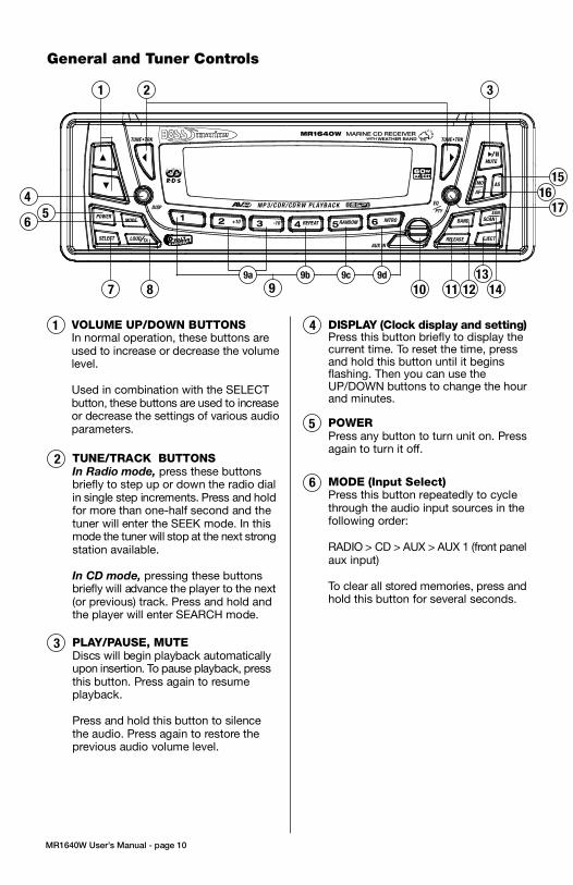
3. Push the panel mechanism back
into the housing so it is not protruding.
To do so, push the BOTTOM EDGE
down straight into the unit – do not
lift it! (Figure 7).
4. Immediately place the front panel
in its protective case for safe and
clean storage (Figure 8).
EON
EON
CONTENTS
MR1640W User’s Manual - page 1
U S E R ’ S M A N U A L
General and Tuner Controls
MR1640W User’s Manual - page 10 MR1640W User’s Manual - page 11
Wiring diagram
MR1640W User’s Manual - page 18
Troubleshooting
MR1640W User’s Manual - page 19
Specifications
MR1640W User’s Manual - page 20
MR1640W User’s Manual - page 4 MR1640W User’s Manual - page 5
Removing the head unit
Remote Control
MR1640W User’s Manual - page 14
General and Tuner Controls, continued
MR1640W User’s Manual - page 12 MR1640W User’s Manual - page 13
CD playback
MR1640W User’s Manual - page 15
MP3 disc playback
MR1640W User’s Manual - page 17
PTY Station Categories
MR1640W User’s Manual - page 6
Remote control installation
FLUSH MOUNT
MR1640W User’s Manual - page 7
Remote control installation, continued
MR1640W User’s Manual - page 16
RDS Radio functions
MR1640W User’s Manual - page 8
Remote control installation, continued
MR1640W User’s Manual - page 9
Remote control installation, continued
MR1640W User’s Manual - page 2
Head unit installation
MR2080W User’s Manual - page 3
Reinserting the front panelDetaching the front panel
MR1640 Marine MP3/CD Receiver Packing List
RESET button
Weather Band Tuning
Follow the wiring illustration below closely to obtain proper performance from your CDreceiver. Failure to make these connections properly may result in damage to your unitwhich will not be covered under your warranty.
This receiver contains a built-in high power four-channel amplifier. To use the built-inamplifier, connect the speaker wires as shown. To use the receiver as a head unit in a2CH, 4CH or 4CH-plus-subwoofer mobile audio system which includes an amplifier(s)or power subwoofer, use the RCA outputs to connect to the RCA inputs of your amplifier(s).
If you experience operation or performance problems with this product, compare yourinstallation with the electrical wiring diagram on the previous page. If problems persist,read the following troubleshooting tips which may help eliminate the problems.
Should you need to remove the head
unit, first remove and store the front
panel as described on the preceding
page.
After you have removed the front panel,
insert the removal keys supplied with
the head unit into the two removal slots
as shown in the drawing until you feel
a “click.” You can now use the levers
to pull the unit from the mounting
surface. (Figures 10 and 11).
Figure 11 Insert removal keys until “click” occurs,
keys to pull out head unit.
Please follow these general instructions toplay a music CD disc. On the column tothe right, you will find instructions for usingMP3 discs.
Please note that only some of thesefunctions are available on the remote control.
Loading a discPress down the latch on the disc door asshown in the figure below, and then pushit down to open the door.
Gently insert a disc into the disc slot untilyou feel it being drawn in by the playermechanism. If there is already a disc in theplayer, first press EJECT to eject it andremove it.
Playing a discThe disc will begin playing automatically. Ifyou wish to pause playback, pressPLAY/PAUSE, and press again to resumeplayback.
To start playback from the first track, pressPRESET 1. To select the next or last tentracks to play, press the +10 or -10 button.
Intro Scan functionThe Intro Scan function is a convenient wayto find a particular track. Press this buttonand the player will play the first few secondsof a song, and then skip to the next songand play a few seconds of that song. Thisprocess continues until you press the INTRObutton again, and the player will continueplaying that song.
Repeating a trackTo keep repeating the same track, pressthe REPEAT button. To cancel the repeatfunction, press again.
Random playPressing the RANDOM will cause the playerto play all the songs on the current disc inrandom order. Press again to cancel thisfunction.
When you insert an MP3 (or WMA) disc,the player will begin playback from the firsttrack in the directory.
However, MP3 discs can contain manymore tracks than audio CD’s, so you maywish to search for a particular track to play.There are three search methods available.
TRACK SEARCH MODE
In disc playback mode, press the BANDbutton once. The LCD will display the word“TRACK.”
To begin searching, press SELECT or theUP/DOWN button. Then press and holdthe UP or DOWN button to locate thedesired track, and press SELECT to beginplayback.
NAVIGATE THE CURRENT FOLDER
This mode permits you to navigate the filedirectory present on the disc.
To enter this mode, press BAND twice. Thedisplay will display “NAVIGA.” PressSELECT to enter this mode.
Use the UP and DOWN buttons to moveup and down the directory of folders andfiles on the disc. To enter a subfolder ,highlight it and press SELECT. You will thensee the directory of that subfolder and canselect tracks within it. So play a track,highlight it and push SELECT.
VIEWING MP3 FILE INFORMATION
Since many MP3 files are tagged withMusic/Artist/Album (ID3-TAG) information,you can see this as a list by pressing AS/PSrepeatedly.
The information will appear as a scrollingdisplay, including the folder and file nameas well as the ID3-TAG information.
Please note that if this information is notpresent in ID3-TAG version 1.0 or 2.0 format,it will not be displayed.
Push down on latch torelease it, then push it down toopen the door.
FRONT AUDIO OUTPUTSBROWN CABLE
REAR AUDIO OUTPUTSGREY CABLE
RIGHT CH (RED)
LEFT CH (WHITE)
RIGHT CH (RED)
LEFT CH (WHITE)
ISO CONVERSIONCONNECTOR
OPTIONAL POWER AMPLIFIER
SPEAKER IMPEDANCE
MINIMUM 4 OHMS!
SPEAKER IMPEDANCE
MINIMUM 4 OHMS!
Place O-ring in groove on rear surface of flange of cup.
Follow these steps for a successful
installation:
1. Select the proper location which
accomodates the 3.45” overall
diameter, and mark its centerpoint.
2. Drill a hole with diameter of 3.2”-
3.3” (82-84mm). It is very important
that the hole does not exceed 3.3”.TA (Traffic Announcement)Many FM stations offer trafficannouncements in addition to their regularprogramming.
If you enable the TA function by pressingthe TA button, when this station broadcastsa traffic advisory, the radio’s RDS tuner willautomatically interrupt the regular programand play the alert. When the alert is finished,normal play of the broadcast will resume.
The TA function will also interrupt CD andMP3 playback temporarily if the EON featurehas been enabled (see below).
There are some other settings for TAbehavior that you can change. See theSELECT instructions on page 9 for moreinformation.
PTY (Program type)A number of RDS stations can be selectedby the type of program they broadcast, i.e.news, sport or classical music.
Press and hold the PTY button to cause thetuner to switch to RDS PTY type tuning. If atany time you wish to return to normal tuningmode, press and hold again.
When you have entered PTY mode, thedisplay will show “PTY” indicating that themode is enabled, and the name of the firstprogram type, “NEWS.”
To view other PTY categories, use theUP/DOWN buttons (a list of these categoriesis shown on the next page). To select thecategory, highlight it and press SELECT. Ifthere is no station found in that category, thedisplay will show “NONE PTY” and the radiowill return to normal mode.
3. Place the O-ring provided in the
groove on the rear surface of the flange
of the mounting cup.
4. Insert mounting arms fully into
mounting tube.
Mounting arms
Mounting tube
5. Insert mounting screws provided
through the slots in the cup and into
the threaded holes in the mounting
arms. Do not tighten more than a few
turns.
6. Insert this assembly fully into the
hole you have cut so that the flange
rests on the the mounting surface.
Be sure the cup is oriented with
arrow next to the word TOP is
pointing UP or your remote will be
turned when it is installed!
Insert the cup assembly fully into
the hole you have cut.
1. Place the mounting cup in the
location you wish to install it.
Using screws of suitable size and type
for your application, attach the cup to
the mounting surface. If necessary,
drill pilot holes for the screws first.
3. Press the cable into the curved
groove on the back of the remote
housing. Feed the cable end thru the
relief hole at the BACK of the cup OR
the bottom of the cup.
Be sure the cup is oriented with
arrow next to the word TOP is
pointing UP or your remote will be
turned when it is installed!
6. Grasp and turn the remote to the right
until it is in the correct position.
9. Press the cable into the curved
groove on the back of the remote
housing. Feed the cable end thru the
relief hole at the back of the cup.
10. Hold the remote in front of the cup
with the top up, and as you hold it, rotate
it about 20º counterclockwise.
11. Insert the remote control fully into the
cup so that the mounting hooks penetrate
the slots in the back of the cup.
If you feel resistance when you insert the
remote into the cup, pull the remote
housing and check that the cable has been
pressed into the curved slot, as described
in Step 2).
12. Grasp and turn the remote to the right
until it is in the correct position.
5. Insert the remote control fully into
the cup so that the mounting hooks
go through the slots in the back of the
cup.
If your installation is one in which the
cable is exiting out the bottom of the
housing (NOT the back), as you insert
the remote module pull the cable down
gently so it does not interfere with the
insertion of the remote into the cup.
4. Hold the remote in front of the cup
with the top up, and as you hold it,
rotate it about 20º counterclockwise.
2. If you are going to run the cable into
a hole in the mounting surface, drill a
hole of at least 9/16” (15mm) so that
you can pass the remote cable
connector through it.
If you are going to run the cable out
the bottom relief hole and out along
the mounting surface, skip this step.
If you feel resistance when you insert
the remote into the cup, pull the remote
housing out and check that the cable
has been pressed into the curved slot,
as described in Step 3).
To ensure that the installation
meets the IPX5 Waterproof
Standard, please follow these steps
carefully.
1. Remove the transport screws from
the top of the enclosure before
beginning the installation.
Fig 1 Remove transport screws
2. Place the two pieces of plastic film
provided over the two screw holes to
prevent water penetration.
Figure 2 Apply plastic film to seal screw holes
Figure 3 Bending the support tabs
Figure 9 Insert one end of the panel into the opening
in the main unit. Then push the other end of the
panel into main unit until you hear a “click”
1. Insert one side of the panel fully
into the opening in the main unit.
2. Then push the other end of the
front panel into the main body. You
should hear a “click.” (Figure 9)
NOTE: If the panel fails to lock into
position properly, the function of
some controls may be impaired,
and some segments of the display
may not become illuminated. If this
occurs, press RELEASE and reinstall
the front panel.
1. Press the RELEASE button to
release the panel from the right side
of the head unit (Figure 5).
2. Press the panel release latch on
the front edge of the lower surface of
faceplate, and at the same time pull
the panel forward to disengage it from
the main unit. (Figure 6).
Figure 5 Press RELEASE to release the front panel
RELEASE button
Figure 8 Place the front panel in its protective case
PUSH HERE in this direction
Figure 10 Slots for removal keys
Removal key slots
Before installing your new CD Receiver, please unpack the contents and check
that your package contains the following items:
RDS EON function settingThe RDS EON system extends thefunctionality of the TA sensing to a widerrange of traffic announcements from bothlocal and national sources. It also allows theunit to interrupt disc playback with theseannouncements. In addition, it will play theseannouncements (at normal listening level)even if the audio has been muted.
(To set this level, see instructions on page9 for setting V-PGM level).
To enable the EON function, press and holdthe SCAN button. Press again to disable it.
With EON enabled, when a trafficannouncement is broadcast, the radio willswitch automatically to TA mode, and “TP”(Traffic Program) will be displayed.
2 Head unit installation
4 Detaching the front panel
5 Removing the head unit
6 Remote control installationFlush mount
6 Remote control installationSurface mount
10 General and tuner controls
14 Remote control
15 CD Playback
15 MP3 playback
16 RDS radio functions
16 PTY station categories
17 Weather band tuning
18 Wiring diagram
19 Troubleshooting
20 Specifications
Congratulations on your
purchase of a Marine
Weather Band MP3/CD
Receiver.
It has been designed, engineered
and manufactured to bring you
the highest level of performance
and quality, and will afford you
years of listening pleasure.
Thank you for making
Marine your choice for
marine audio entertainment!
page
RDS EuropeanFrequency Model SYMPTOM CAUSE REMEDY
POWER
Press any button to turn unit on. Pressagain to turn it off.
5
TUNE/TRACK BUTTONS
In Radio mode, press these buttonsbriefly to step up or down the radio dialin single step increments. Press and holdfor more than one-half second and thetuner will enter the SEEK mode. In thismode the tuner will stop at the next strongstation available.
In CD mode, pressing these buttonsbriefly will advance the player to the next(or previous) track. Press and hold andthe player will enter SEARCH mode.
2
MODE (Input Select)Press this button repeatedly to cyclethrough the audio input sources in thefollowing order:
RADIO > CD > AUX > AUX 1 (front panelaux input)
To clear all stored memories, press andhold this button for several seconds.
6
• Beep (when you press a button): ON/OFF
• Clock On (determines if clock will bedisplayed when radio is turned off):ON/OFF
• LCD1/2 (LCD brightness level): 1/2
RDS Radio Settings• SEEK/RDS ALLThis setting determines the behavior ofthe radio SEEK function when RDS tuningmode. If ALL is selected, the SEEKfunction will stop at both RDS and non-RDS stations. Otherwise, it will only seekRDS stations. RDS/ALL
• TA (Traffic Alert) SEEK/ALARMWhen TA mode is on, the radio monitorsthe Public Information channel which ispiggy-backed on the FM channel you arecurrently enjoying. If such a channel is notdetected or is weak the tuner will SEEKanother PI channel and monitor it.( Thisis the TA SEEK setting).
If ALARM setting is chosen, if a signal isinsufficiently strong, instead of monitoringan alternate station for PI information, theradio will produce a double beep (alarm)and silence itself, and display “LOST TPTA.” TA SEEK/ALARM
• TA VOLUMEThis setting determines the volume levelof the Traffic Alerts as they play.0-40 (18 is default)
• REG ON/OFFThis setting determines the behavior ofthe radio reception when AF (AlternateFrequency) mode is on. The AF systemcontinuously monitors the signal strengthof a station and compares it with otherstations on the same network. If anotherstation is stronger, it changes to thatstation.
Since sometimes in different regionsstations on the same network will playdifferent programs, the AF system caninterrupt the current program. If REG ONis selected, the station will check if theprograms are the same, and if not, the TAsystem will not change the station.REG OFF/ON
To turn on EON mode of RDS System,press and hold this button. When theEON function is turned on, “EON” willbe displayed on the screen (for moreinformation about the EON function seepage 16).
VOLUME UP/DOWN BUTTONSIn normal operation, these buttons areused to increase or decrease the volumelevel.
Used in combination with the SELECTbutton, these buttons are used to increaseor decrease the settings of various audioparameters.
1
PLAY/PAUSE, MUTE
Discs will begin playback automaticallyupon insertion. To pause playback, pressthis button. Press again to resumeplayback.
Press and hold this button to silencethe audio. Press again to restore theprevious audio volume level.
3
DISPLAY (Clock display and setting)Press this button briefly to display thecurrent time. To reset the time, pressand hold this button until it beginsflashing. Then you can use theUP/DOWN buttons to change the hourand minutes.
4
�
1
87 9
2 3
12
15
14
4
5
16
17
13
1110
9a 9b 9c 9d
6
This list shows the PTY program types in theorder presented in the radio display:
NEWS
AFFAIRS
INFORMATION
SPORTS
EDUCATION
DRAMA
CULTURE
SCIENCE
VARIETY
POP MUSIC
ROCK MUSIC
EASY LISTENING MUSIC
LIGHT MUSIC
CLASSICAL MUSIC
OTHER MUSIC
WEATHER
FINANCE
CHILDREN
SOCIAL
RELIGIOUS
PHONE IN
TRAVEL
LEISURE
JAZZ MUSIC
COUNTRY MUSIC
NATIONAL MUSIC
OLDIES MUSIC
FOLK MUSIC
DOCUMENTARY
ALERT TEST
ALARM TEST
3. Insert and tighten the “headless”
support screw into the back of the
head unit where shown.
4. Insert the mounting case for the
head unit into the dashboard. Inspect
the dashboard material to determine
its approximate thickness. Select the
appropriate support tabs and bend
them outward to secure the bracket
in place (Figure 3).
5. Bend the backstrap to conform to
the mounting case and the dashboard
surface to which you plan to secure
the backstrap (Figure 4). Slide one of
the utility holes on the backstrap onto
the support screw and fasten it with
the spring washer and nut provided.
6. Using the 5 x 25mm screw and the
plain washer, secure the backstrap to
the dashboard surface as shown in
the diagram. Tighten, secure, and
check the overall mounting to be sure
it is safe and will not release in an
emergency stop or other sudden
movement of the vehicle.
Weather band listening is available usingTUNE/TRK buttons or the radio presets.
To hear the weather band stations, press theBAND button until the weather band isdisplayed.
The six preset buttons are assigned to thefollowing frequencies and cannot be changed:
PRESET # Frequency, MHz
1 162.40
2 162.43
3 162.45
4 162.47
5 162.50
6 162.53
if you wish to tune to the 7th available frequency,162.55MHz, use the TUNE/TRK buttons tolocate it.
Please note that in Weather Band, the followingbuttons are not operable:
SCANAS/PS
Mounting
surface
Drill a 9/16”
(15mm) or
larger hole to
allow cable to
pass through
mounting
surface.
Intallation with cable going
into hole in mounting surface.
Intallation with cable running out on top
of mounting surface.
Figure 6 Press release latch on on the lower surfaceof the front edge of the panel and pull the panel until itis free of the head unit.
Figure 7 Push the panel mechanism back in
Slide the screws out to
extend the mounting arms
so that they reach behind
the mounting surface.
Insert the mounting screws through
the cup into the threaded holes
in the mounting arms
Hold the remote in front of
the cup, turned about
20º counterclockwise.
- OR -
4CHX
60W
TUNE•TRK TUNE•TRK
DISPEQ
PTY
AUX IN
MR1640W MARINE CD RECEIVERWEATHER BANDWITH
1 2 3 4 5 6POWER
MODE
SELECT
MUTE
EJECTRELEASE
BAND SCAN
MO
AF
AS
LOUD TA
+10 -10 REPEAT RANDOM INTRO
MP 3/C DR/CD RW PLAYBAC K

3. Push the panel mechanism back
into the housing so it is not protruding.
To do so, push the BOTTOM EDGE
down straight into the unit – do not
lift it! (Figure 7).
4. Immediately place the front panel
in its protective case for safe and
clean storage (Figure 8).
EON
EON
CONTENTS
MR1640W User’s Manual - page 1
U S E R ’ S M A N U A L
General and Tuner Controls
MR1640W User’s Manual - page 10 MR1640W User’s Manual - page 11
Wiring diagram
MR1640W User’s Manual - page 18
Troubleshooting
MR1640W User’s Manual - page 19
Specifications
MR1640W User’s Manual - page 20
MR1640W User’s Manual - page 4 MR1640W User’s Manual - page 5
Removing the head unit
Remote Control
MR1640W User’s Manual - page 14
General and Tuner Controls, continued
MR1640W User’s Manual - page 12 MR1640W User’s Manual - page 13
CD playback
MR1640W User’s Manual - page 15
MP3 disc playback
MR1640W User’s Manual - page 17
PTY Station Categories
MR1640W User’s Manual - page 6
Remote control installation
FLUSH MOUNT
MR1640W User’s Manual - page 7
Remote control installation, continued
MR1640W User’s Manual - page 16
RDS Radio functions
MR1640W User’s Manual - page 8
Remote control installation, continued
MR1640W User’s Manual - page 9
Remote control installation, continued
MR1640W User’s Manual - page 2
Head unit installation
MR2080W User’s Manual - page 3
Reinserting the front panelDetaching the front panel
MR1640 Marine MP3/CD Receiver Packing List
RESET button
Weather Band Tuning
Follow the wiring illustration below closely to obtain proper performance from your CDreceiver. Failure to make these connections properly may result in damage to your unitwhich will not be covered under your warranty.
This receiver contains a built-in high power four-channel amplifier. To use the built-inamplifier, connect the speaker wires as shown. To use the receiver as a head unit in a2CH, 4CH or 4CH-plus-subwoofer mobile audio system which includes an amplifier(s)or power subwoofer, use the RCA outputs to connect to the RCA inputs of your amplifier(s).
If you experience operation or performance problems with this product, compare yourinstallation with the electrical wiring diagram on the previous page. If problems persist,read the following troubleshooting tips which may help eliminate the problems.
Should you need to remove the head
unit, first remove and store the front
panel as described on the preceding
page.
After you have removed the front panel,
insert the removal keys supplied with
the head unit into the two removal slots
as shown in the drawing until you feel
a “click.” You can now use the levers
to pull the unit from the mounting
surface. (Figures 10 and 11).
Figure 11 Insert removal keys until “click” occurs,
keys to pull out head unit.
Please follow these general instructions toplay a music CD disc. On the column tothe right, you will find instructions for usingMP3 discs.
Please note that only some of thesefunctions are available on the remote control.
Loading a discPress down the latch on the disc door asshown in the figure below, and then pushit down to open the door.
Gently insert a disc into the disc slot untilyou feel it being drawn in by the playermechanism. If there is already a disc in theplayer, first press EJECT to eject it andremove it.
Playing a discThe disc will begin playing automatically. Ifyou wish to pause playback, pressPLAY/PAUSE, and press again to resumeplayback.
To start playback from the first track, pressPRESET 1. To select the next or last tentracks to play, press the +10 or -10 button.
Intro Scan functionThe Intro Scan function is a convenient wayto find a particular track. Press this buttonand the player will play the first few secondsof a song, and then skip to the next songand play a few seconds of that song. Thisprocess continues until you press the INTRObutton again, and the player will continueplaying that song.
Repeating a trackTo keep repeating the same track, pressthe REPEAT button. To cancel the repeatfunction, press again.
Random playPressing the RANDOM will cause the playerto play all the songs on the current disc inrandom order. Press again to cancel thisfunction.
When you insert an MP3 (or WMA) disc,the player will begin playback from the firsttrack in the directory.
However, MP3 discs can contain manymore tracks than audio CD’s, so you maywish to search for a particular track to play.There are three search methods available.
TRACK SEARCH MODE
In disc playback mode, press the BANDbutton once. The LCD will display the word“TRACK.”
To begin searching, press SELECT or theUP/DOWN button. Then press and holdthe UP or DOWN button to locate thedesired track, and press SELECT to beginplayback.
NAVIGATE THE CURRENT FOLDER
This mode permits you to navigate the filedirectory present on the disc.
To enter this mode, press BAND twice. Thedisplay will display “NAVIGA.” PressSELECT to enter this mode.
Use the UP and DOWN buttons to moveup and down the directory of folders andfiles on the disc. To enter a subfolder ,highlight it and press SELECT. You will thensee the directory of that subfolder and canselect tracks within it. So play a track,highlight it and push SELECT.
VIEWING MP3 FILE INFORMATION
Since many MP3 files are tagged withMusic/Artist/Album (ID3-TAG) information,you can see this as a list by pressing AS/PSrepeatedly.
The information will appear as a scrollingdisplay, including the folder and file nameas well as the ID3-TAG information.
Please note that if this information is notpresent in ID3-TAG version 1.0 or 2.0 format,it will not be displayed.
Push down on latch torelease it, then push it down toopen the door.
FRONT AUDIO OUTPUTSBROWN CABLE
REAR AUDIO OUTPUTSGREY CABLE
RIGHT CH (RED)
LEFT CH (WHITE)
RIGHT CH (RED)
LEFT CH (WHITE)
ISO CONVERSIONCONNECTOR
OPTIONAL POWER AMPLIFIER
SPEAKER IMPEDANCE
MINIMUM 4 OHMS!
SPEAKER IMPEDANCE
MINIMUM 4 OHMS!
Place O-ring in groove on rear surface of flange of cup.
Follow these steps for a successful
installation:
1. Select the proper location which
accomodates the 3.45” overall
diameter, and mark its centerpoint.
2. Drill a hole with diameter of 3.2”-
3.3” (82-84mm). It is very important
that the hole does not exceed 3.3”.TA (Traffic Announcement)Many FM stations offer trafficannouncements in addition to their regularprogramming.
If you enable the TA function by pressingthe TA button, when this station broadcastsa traffic advisory, the radio’s RDS tuner willautomatically interrupt the regular programand play the alert. When the alert is finished,normal play of the broadcast will resume.
The TA function will also interrupt CD andMP3 playback temporarily if the EON featurehas been enabled (see below).
There are some other settings for TAbehavior that you can change. See theSELECT instructions on page 9 for moreinformation.
PTY (Program type)A number of RDS stations can be selectedby the type of program they broadcast, i.e.news, sport or classical music.
Press and hold the PTY button to cause thetuner to switch to RDS PTY type tuning. If atany time you wish to return to normal tuningmode, press and hold again.
When you have entered PTY mode, thedisplay will show “PTY” indicating that themode is enabled, and the name of the firstprogram type, “NEWS.”
To view other PTY categories, use theUP/DOWN buttons (a list of these categoriesis shown on the next page). To select thecategory, highlight it and press SELECT. Ifthere is no station found in that category, thedisplay will show “NONE PTY” and the radiowill return to normal mode.
3. Place the O-ring provided in the
groove on the rear surface of the flange
of the mounting cup.
4. Insert mounting arms fully into
mounting tube.
Mounting arms
Mounting tube
5. Insert mounting screws provided
through the slots in the cup and into
the threaded holes in the mounting
arms. Do not tighten more than a few
turns.
6. Insert this assembly fully into the
hole you have cut so that the flange
rests on the the mounting surface.
Be sure the cup is oriented with
arrow next to the word TOP is
pointing UP or your remote will be
turned when it is installed!
Insert the cup assembly fully into
the hole you have cut.
1. Place the mounting cup in the
location you wish to install it.
Using screws of suitable size and type
for your application, attach the cup to
the mounting surface. If necessary,
drill pilot holes for the screws first.
3. Press the cable into the curved
groove on the back of the remote
housing. Feed the cable end thru the
relief hole at the BACK of the cup OR
the bottom of the cup.
Be sure the cup is oriented with
arrow next to the word TOP is
pointing UP or your remote will be
turned when it is installed!
6. Grasp and turn the remote to the right
until it is in the correct position.
9. Press the cable into the curved
groove on the back of the remote
housing. Feed the cable end thru the
relief hole at the back of the cup.
10. Hold the remote in front of the cup
with the top up, and as you hold it, rotate
it about 20º counterclockwise.
11. Insert the remote control fully into the
cup so that the mounting hooks penetrate
the slots in the back of the cup.
If you feel resistance when you insert the
remote into the cup, pull the remote
housing and check that the cable has been
pressed into the curved slot, as described
in Step 2).
12. Grasp and turn the remote to the right
until it is in the correct position.
5. Insert the remote control fully into
the cup so that the mounting hooks
go through the slots in the back of the
cup.
If your installation is one in which the
cable is exiting out the bottom of the
housing (NOT the back), as you insert
the remote module pull the cable down
gently so it does not interfere with the
insertion of the remote into the cup.
4. Hold the remote in front of the cup
with the top up, and as you hold it,
rotate it about 20º counterclockwise.
2. If you are going to run the cable into
a hole in the mounting surface, drill a
hole of at least 9/16” (15mm) so that
you can pass the remote cable
connector through it.
If you are going to run the cable out
the bottom relief hole and out along
the mounting surface, skip this step.
If you feel resistance when you insert
the remote into the cup, pull the remote
housing out and check that the cable
has been pressed into the curved slot,
as described in Step 3).
To ensure that the installation
meets the IPX5 Waterproof
Standard, please follow these steps
carefully.
1. Remove the transport screws from
the top of the enclosure before
beginning the installation.
Fig 1 Remove transport screws
2. Place the two pieces of plastic film
provided over the two screw holes to
prevent water penetration.
Figure 2 Apply plastic film to seal screw holes
Figure 3 Bending the support tabs
Figure 9 Insert one end of the panel into the opening
in the main unit. Then push the other end of the
panel into main unit until you hear a “click”
1. Insert one side of the panel fully
into the opening in the main unit.
2. Then push the other end of the
front panel into the main body. You
should hear a “click.” (Figure 9)
NOTE: If the panel fails to lock into
position properly, the function of
some controls may be impaired,
and some segments of the display
may not become illuminated. If this
occurs, press RELEASE and reinstall
the front panel.
1. Press the RELEASE button to
release the panel from the right side
of the head unit (Figure 5).
2. Press the panel release latch on
the front edge of the lower surface of
faceplate, and at the same time pull
the panel forward to disengage it from
the main unit. (Figure 6).
Figure 5 Press RELEASE to release the front panel
RELEASE button
Figure 8 Place the front panel in its protective case
PUSH HERE in this direction
Figure 10 Slots for removal keys
Removal key slots
Before installing your new CD Receiver, please unpack the contents and check
that your package contains the following items:
RDS EON function settingThe RDS EON system extends thefunctionality of the TA sensing to a widerrange of traffic announcements from bothlocal and national sources. It also allows theunit to interrupt disc playback with theseannouncements. In addition, it will play theseannouncements (at normal listening level)even if the audio has been muted.
(To set this level, see instructions on page9 for setting V-PGM level).
To enable the EON function, press and holdthe SCAN button. Press again to disable it.
With EON enabled, when a trafficannouncement is broadcast, the radio willswitch automatically to TA mode, and “TP”(Traffic Program) will be displayed.
2 Head unit installation
4 Detaching the front panel
5 Removing the head unit
6 Remote control installationFlush mount
6 Remote control installationSurface mount
10 General and tuner controls
14 Remote control
15 CD Playback
15 MP3 playback
16 RDS radio functions
16 PTY station categories
17 Weather band tuning
18 Wiring diagram
19 Troubleshooting
20 Specifications
Congratulations on your
purchase of a Marine
Weather Band MP3/CD
Receiver.
It has been designed, engineered
and manufactured to bring you
the highest level of performance
and quality, and will afford you
years of listening pleasure.
Thank you for making
Marine your choice for
marine audio entertainment!
page
RDS EuropeanFrequency Model SYMPTOM CAUSE REMEDY
• Beep (when you press a button): ON/OFF
• Clock On (determines if clock will bedisplayed when radio is turned off):ON/OFF
• LCD1/2 (LCD brightness level): 1/2
RDS Radio Settings• SEEK/RDS ALLThis setting determines the behavior ofthe radio SEEK function when RDS tuningmode. If ALL is selected, the SEEKfunction will stop at both RDS and non-RDS stations. Otherwise, it will only seekRDS stations. RDS/ALL
• TA (Traffic Alert) SEEK/ALARMWhen TA mode is on, the radio monitorsthe Public Information channel which ispiggy-backed on the FM channel you arecurrently enjoying. If such a channel is notdetected or is weak the tuner will SEEKanother PI channel and monitor it.( Thisis the TA SEEK setting).
If ALARM setting is chosen, if a signal isinsufficiently strong, instead of monitoringan alternate station for PI information, theradio will produce a double beep (alarm)and silence itself, and display “LOST TPTA.” TA SEEK/ALARM
• TA VOLUMEThis setting determines the volume levelof the Traffic Alerts as they play.0-40 (18 is default)
• REG ON/OFFThis setting determines the behavior ofthe radio reception when AF (AlternateFrequency) mode is on. The AF systemcontinuously monitors the signal strengthof a station and compares it with otherstations on the same network. If anotherstation is stronger, it changes to thatstation.
Since sometimes in different regionsstations on the same network will playdifferent programs, the AF system caninterrupt the current program. If REG ONis selected, the station will check if theprograms are the same, and if not, the TAsystem will not change the station.REG OFF/ON
SELECTThe SELECT button is used to access awide range of settings for the receiver.
AUDIO SETTINGSTo change settings in the audio section,press SELECT briefly, repeatedly, to stepthru the following audio parameters:
VOLUME > BASS > TREBLE > BALANCE> FADER
In each parameter, the unit waits about 5seconds for you to use the UP or DOWNbutton to adjust the setting.
Please note: If you have selected a preset EQcurve, the settings for BASS and TREBLE willnot be available in the Audio Settings section.
SYSTEM SETTINGSGeneral SettingsTo access system setup items, press andhold SELECT for more than two seconds.
The LCD will display “MENU” and then willdisplay the first adjustable item, which is“CLOCK.”
Press SELECT briefly to step thru theavailable settings. Use the UP/DOWNbuttons to make any changes. Thefollowing list shows the sequence of itemsin the menu, and the choices possible. Thefactory default is indicated in bold type.
• Clock 12HR/24HR: 12HR or 24HR Inareas with US frequencies 12 HR, in areaswith European frequencies, 24HR.
• Clock time: If the frequency area switches from American to European, the clock willdisplay 24:00. Similarly if the area switchesfrom European to American, the clock willdisplay 12:00. Use the UP/DOWN buttonsto adjust the minutes or hours.
• Subwoofer channel: ON/OFF
• LOC/DX radio reception: LOC/DX• Area: Factory set to the country in whichthe radio is sold. Europe > Latin > OIRT> AUST > ASIA > USA
• V-PGM (maximum volume level): 0-12
7
To turn on EON mode of RDS System,press and hold this button. When theEON function is turned on, “EON” willbe displayed on the screen (for moreinformation about the EON function seepage 16).
This list shows the PTY program types in theorder presented in the radio display:
NEWS
AFFAIRS
INFORMATION
SPORTS
EDUCATION
DRAMA
CULTURE
SCIENCE
VARIETY
POP MUSIC
ROCK MUSIC
EASY LISTENING MUSIC
LIGHT MUSIC
CLASSICAL MUSIC
OTHER MUSIC
WEATHER
FINANCE
CHILDREN
SOCIAL
RELIGIOUS
PHONE IN
TRAVEL
LEISURE
JAZZ MUSIC
COUNTRY MUSIC
NATIONAL MUSIC
OLDIES MUSIC
FOLK MUSIC
DOCUMENTARY
ALERT TEST
ALARM TEST
3. Insert and tighten the “headless”
support screw into the back of the
head unit where shown.
4. Insert the mounting case for the
head unit into the dashboard. Inspect
the dashboard material to determine
its approximate thickness. Select the
appropriate support tabs and bend
them outward to secure the bracket
in place (Figure 3).
5. Bend the backstrap to conform to
the mounting case and the dashboard
surface to which you plan to secure
the backstrap (Figure 4). Slide one of
the utility holes on the backstrap onto
the support screw and fasten it with
the spring washer and nut provided.
6. Using the 5 x 25mm screw and the
plain washer, secure the backstrap to
the dashboard surface as shown in
the diagram. Tighten, secure, and
check the overall mounting to be sure
it is safe and will not release in an
emergency stop or other sudden
movement of the vehicle.
Weather band listening is available usingTUNE/TRK buttons or the radio presets.
To hear the weather band stations, press theBAND button until the weather band isdisplayed.
The six preset buttons are assigned to thefollowing frequencies and cannot be changed:
PRESET # Frequency, MHz
1 162.40
2 162.43
3 162.45
4 162.47
5 162.50
6 162.53
if you wish to tune to the 7th available frequency,162.55MHz, use the TUNE/TRK buttons tolocate it.
Please note that in Weather Band, the followingbuttons are not operable:
SCANAS/PS
Mounting
surface
Drill a 9/16”
(15mm) or
larger hole to
allow cable to
pass through
mounting
surface.
Intallation with cable going
into hole in mounting surface.
Intallation with cable running out on top
of mounting surface.
Figure 6 Press release latch on on the lower surfaceof the front edge of the panel and pull the panel until itis free of the head unit.
Figure 7 Push the panel mechanism back in
Slide the screws out to
extend the mounting arms
so that they reach behind
the mounting surface.
Insert the mounting screws through
the cup into the threaded holes
in the mounting arms
Hold the remote in front of
the cup, turned about
20º counterclockwise.
- OR -

3. Push the panel mechanism back
into the housing so it is not protruding.
To do so, push the BOTTOM EDGE
down straight into the unit – do not
lift it! (Figure 7).
4. Immediately place the front panel
in its protective case for safe and
clean storage (Figure 8).
EON
EON
CONTENTS
MR1640W User’s Manual - page 1
U S E R ’ S M A N U A L
General and Tuner Controls
MR1640W User’s Manual - page 10 MR1640W User’s Manual - page 11
Wiring diagram
MR1640W User’s Manual - page 18
Troubleshooting
MR1640W User’s Manual - page 19
Specifications
MR1640W User’s Manual - page 20
MR1640W User’s Manual - page 4 MR1640W User’s Manual - page 5
Removing the head unit
Remote Control
MR1640W User’s Manual - page 14
General and Tuner Controls, continued
MR1640W User’s Manual - page 12 MR1640W User’s Manual - page 13
CD playback
MR1640W User’s Manual - page 15
MP3 disc playback
MR1640W User’s Manual - page 17
PTY Station Categories
MR1640W User’s Manual - page 6
Remote control installation
FLUSH MOUNT
MR1640W User’s Manual - page 7
Remote control installation, continued
MR1640W User’s Manual - page 16
RDS Radio functions
MR1640W User’s Manual - page 8
Remote control installation, continued
MR1640W User’s Manual - page 9
Remote control installation, continued
MR1640W User’s Manual - page 2
Head unit installation
MR2080W User’s Manual - page 3
Reinserting the front panelDetaching the front panel
MR1640 Marine MP3/CD Receiver Packing List
RESET button
Weather Band Tuning
Follow the wiring illustration below closely to obtain proper performance from your CDreceiver. Failure to make these connections properly may result in damage to your unitwhich will not be covered under your warranty.
This receiver contains a built-in high power four-channel amplifier. To use the built-inamplifier, connect the speaker wires as shown. To use the receiver as a head unit in a2CH, 4CH or 4CH-plus-subwoofer mobile audio system which includes an amplifier(s)or power subwoofer, use the RCA outputs to connect to the RCA inputs of your amplifier(s).
If you experience operation or performance problems with this product, compare yourinstallation with the electrical wiring diagram on the previous page. If problems persist,read the following troubleshooting tips which may help eliminate the problems.
Should you need to remove the head
unit, first remove and store the front
panel as described on the preceding
page.
After you have removed the front panel,
insert the removal keys supplied with
the head unit into the two removal slots
as shown in the drawing until you feel
a “click.” You can now use the levers
to pull the unit from the mounting
surface. (Figures 10 and 11).
Figure 11 Insert removal keys until “click” occurs,
keys to pull out head unit.
Please follow these general instructions toplay a music CD disc. On the column tothe right, you will find instructions for usingMP3 discs.
Please note that only some of thesefunctions are available on the remote control.
Loading a discPress down the latch on the disc door asshown in the figure below, and then pushit down to open the door.
Gently insert a disc into the disc slot untilyou feel it being drawn in by the playermechanism. If there is already a disc in theplayer, first press EJECT to eject it andremove it.
Playing a discThe disc will begin playing automatically. Ifyou wish to pause playback, pressPLAY/PAUSE, and press again to resumeplayback.
To start playback from the first track, pressPRESET 1. To select the next or last tentracks to play, press the +10 or -10 button.
Intro Scan functionThe Intro Scan function is a convenient wayto find a particular track. Press this buttonand the player will play the first few secondsof a song, and then skip to the next songand play a few seconds of that song. Thisprocess continues until you press the INTRObutton again, and the player will continueplaying that song.
Repeating a trackTo keep repeating the same track, pressthe REPEAT button. To cancel the repeatfunction, press again.
Random playPressing the RANDOM will cause the playerto play all the songs on the current disc inrandom order. Press again to cancel thisfunction.
When you insert an MP3 (or WMA) disc,the player will begin playback from the firsttrack in the directory.
However, MP3 discs can contain manymore tracks than audio CD’s, so you maywish to search for a particular track to play.There are three search methods available.
TRACK SEARCH MODE
In disc playback mode, press the BANDbutton once. The LCD will display the word“TRACK.”
To begin searching, press SELECT or theUP/DOWN button. Then press and holdthe UP or DOWN button to locate thedesired track, and press SELECT to beginplayback.
NAVIGATE THE CURRENT FOLDER
This mode permits you to navigate the filedirectory present on the disc.
To enter this mode, press BAND twice. Thedisplay will display “NAVIGA.” PressSELECT to enter this mode.
Use the UP and DOWN buttons to moveup and down the directory of folders andfiles on the disc. To enter a subfolder ,highlight it and press SELECT. You will thensee the directory of that subfolder and canselect tracks within it. So play a track,highlight it and push SELECT.
VIEWING MP3 FILE INFORMATION
Since many MP3 files are tagged withMusic/Artist/Album (ID3-TAG) information,you can see this as a list by pressing AS/PSrepeatedly.
The information will appear as a scrollingdisplay, including the folder and file nameas well as the ID3-TAG information.
Please note that if this information is notpresent in ID3-TAG version 1.0 or 2.0 format,it will not be displayed.
Push down on latch torelease it, then push it down toopen the door.
FRONT AUDIO OUTPUTSBROWN CABLE
REAR AUDIO OUTPUTSGREY CABLE
RIGHT CH (RED)
LEFT CH (WHITE)
RIGHT CH (RED)
LEFT CH (WHITE)
ISO CONVERSIONCONNECTOR
OPTIONAL POWER AMPLIFIER
SPEAKER IMPEDANCE
MINIMUM 4 OHMS!
SPEAKER IMPEDANCE
MINIMUM 4 OHMS!
Place O-ring in groove on rear surface of flange of cup.
Follow these steps for a successful
installation:
1. Select the proper location which
accomodates the 3.45” overall
diameter, and mark its centerpoint.
2. Drill a hole with diameter of 3.2”-
3.3” (82-84mm). It is very important
that the hole does not exceed 3.3”.TA (Traffic Announcement)Many FM stations offer trafficannouncements in addition to their regularprogramming.
If you enable the TA function by pressingthe TA button, when this station broadcastsa traffic advisory, the radio’s RDS tuner willautomatically interrupt the regular programand play the alert. When the alert is finished,normal play of the broadcast will resume.
The TA function will also interrupt CD andMP3 playback temporarily if the EON featurehas been enabled (see below).
There are some other settings for TAbehavior that you can change. See theSELECT instructions on page 9 for moreinformation.
PTY (Program type)A number of RDS stations can be selectedby the type of program they broadcast, i.e.news, sport or classical music.
Press and hold the PTY button to cause thetuner to switch to RDS PTY type tuning. If atany time you wish to return to normal tuningmode, press and hold again.
When you have entered PTY mode, thedisplay will show “PTY” indicating that themode is enabled, and the name of the firstprogram type, “NEWS.”
To view other PTY categories, use theUP/DOWN buttons (a list of these categoriesis shown on the next page). To select thecategory, highlight it and press SELECT. Ifthere is no station found in that category, thedisplay will show “NONE PTY” and the radiowill return to normal mode.
3. Place the O-ring provided in the
groove on the rear surface of the flange
of the mounting cup.
4. Insert mounting arms fully into
mounting tube.
Mounting arms
Mounting tube
5. Insert mounting screws provided
through the slots in the cup and into
the threaded holes in the mounting
arms. Do not tighten more than a few
turns.
6. Insert this assembly fully into the
hole you have cut so that the flange
rests on the the mounting surface.
Be sure the cup is oriented with
arrow next to the word TOP is
pointing UP or your remote will be
turned when it is installed!
Insert the cup assembly fully into
the hole you have cut.
1. Place the mounting cup in the
location you wish to install it.
Using screws of suitable size and type
for your application, attach the cup to
the mounting surface. If necessary,
drill pilot holes for the screws first.
3. Press the cable into the curved
groove on the back of the remote
housing. Feed the cable end thru the
relief hole at the BACK of the cup OR
the bottom of the cup.
Be sure the cup is oriented with
arrow next to the word TOP is
pointing UP or your remote will be
turned when it is installed!
6. Grasp and turn the remote to the right
until it is in the correct position.
9. Press the cable into the curved
groove on the back of the remote
housing. Feed the cable end thru the
relief hole at the back of the cup.
10. Hold the remote in front of the cup
with the top up, and as you hold it, rotate
it about 20º counterclockwise.
11. Insert the remote control fully into the
cup so that the mounting hooks penetrate
the slots in the back of the cup.
If you feel resistance when you insert the
remote into the cup, pull the remote
housing and check that the cable has been
pressed into the curved slot, as described
in Step 2).
12. Grasp and turn the remote to the right
until it is in the correct position.
5. Insert the remote control fully into
the cup so that the mounting hooks
go through the slots in the back of the
cup.
If your installation is one in which the
cable is exiting out the bottom of the
housing (NOT the back), as you insert
the remote module pull the cable down
gently so it does not interfere with the
insertion of the remote into the cup.
4. Hold the remote in front of the cup
with the top up, and as you hold it,
rotate it about 20º counterclockwise.
2. If you are going to run the cable into
a hole in the mounting surface, drill a
hole of at least 9/16” (15mm) so that
you can pass the remote cable
connector through it.
If you are going to run the cable out
the bottom relief hole and out along
the mounting surface, skip this step.
If you feel resistance when you insert
the remote into the cup, pull the remote
housing out and check that the cable
has been pressed into the curved slot,
as described in Step 3).
To ensure that the installation
meets the IPX5 Waterproof
Standard, please follow these steps
carefully.
1. Remove the transport screws from
the top of the enclosure before
beginning the installation.
Fig 1 Remove transport screws
2. Place the two pieces of plastic film
provided over the two screw holes to
prevent water penetration.
Figure 2 Apply plastic film to seal screw holes
Figure 3 Bending the support tabs
Figure 9 Insert one end of the panel into the opening
in the main unit. Then push the other end of the
panel into main unit until you hear a “click”
1. Insert one side of the panel fully
into the opening in the main unit.
2. Then push the other end of the
front panel into the main body. You
should hear a “click.” (Figure 9)
NOTE: If the panel fails to lock into
position properly, the function of
some controls may be impaired,
and some segments of the display
may not become illuminated. If this
occurs, press RELEASE and reinstall
the front panel.
1. Press the RELEASE button to
release the panel from the right side
of the head unit (Figure 5).
2. Press the panel release latch on
the front edge of the lower surface of
faceplate, and at the same time pull
the panel forward to disengage it from
the main unit. (Figure 6).
Figure 5 Press RELEASE to release the front panel
RELEASE button
Figure 8 Place the front panel in its protective case
PUSH HERE in this direction
Figure 10 Slots for removal keys
Removal key slots
Before installing your new CD Receiver, please unpack the contents and check
that your package contains the following items:
RDS EON function settingThe RDS EON system extends thefunctionality of the TA sensing to a widerrange of traffic announcements from bothlocal and national sources. It also allows theunit to interrupt disc playback with theseannouncements. In addition, it will play theseannouncements (at normal listening level)even if the audio has been muted.
(To set this level, see instructions on page9 for setting V-PGM level).
To enable the EON function, press and holdthe SCAN button. Press again to disable it.
With EON enabled, when a trafficannouncement is broadcast, the radio willswitch automatically to TA mode, and “TP”(Traffic Program) will be displayed.
2 Head unit installation
4 Detaching the front panel
5 Removing the head unit
6 Remote control installationFlush mount
6 Remote control installationSurface mount
10 General and tuner controls
14 Remote control
15 CD Playback
15 MP3 playback
16 RDS radio functions
16 PTY station categories
17 Weather band tuning
18 Wiring diagram
19 Troubleshooting
20 Specifications
Congratulations on your
purchase of a Marine
Weather Band MP3/CD
Receiver.
It has been designed, engineered
and manufactured to bring you
the highest level of performance
and quality, and will afford you
years of listening pleasure.
Thank you for making
Marine your choice for
marine audio entertainment!
page
RDS EuropeanFrequency Model SYMPTOM CAUSE REMEDY
+10/-10 (next/previous 10 tracks)These button are used during discplayback to skip ahead or back tentracks.
9a
LOUDNESS/TAPress briefly increase the level of bassoutput. Press again to turn off theLoudness function.
Press a little longer to turn on the TA(Traffic Alert) mode. For more informationabout this mode, please see page 16of this manual)
8
PRESETS 1-6 (Radio Mode)These buttons are used to store thepresets for radio stations. To set a preset,tune to the desired radio station. Thenpress and hold the preset to which youwish to assign that station for more thanone second and release. To replace itwith a different station, repeat theprocess and the new setting will overridethe previous one.
9
RELEASETo remove a disc or take off the frontpanel, first press this button to lowerthe panel.
To remove the front panel, pleaseseethe instructions on page 4.
11
• Beep (when you press a button): ON/OFF
• Clock On (determines if clock will bedisplayed when radio is turned off):ON/OFF
• LCD1/2 (LCD brightness level): 1/2
RDS Radio Settings• SEEK/RDS ALLThis setting determines the behavior ofthe radio SEEK function when RDS tuningmode. If ALL is selected, the SEEKfunction will stop at both RDS and non-RDS stations. Otherwise, it will only seekRDS stations. RDS/ALL
• TA (Traffic Alert) SEEK/ALARMWhen TA mode is on, the radio monitorsthe Public Information channel which ispiggy-backed on the FM channel you arecurrently enjoying. If such a channel is notdetected or is weak the tuner will SEEKanother PI channel and monitor it.( Thisis the TA SEEK setting).
If ALARM setting is chosen, if a signal isinsufficiently strong, instead of monitoringan alternate station for PI information, theradio will produce a double beep (alarm)and silence itself, and display “LOST TPTA.” TA SEEK/ALARM
• TA VOLUMEThis setting determines the volume levelof the Traffic Alerts as they play.0-40 (18 is default)
• REG ON/OFFThis setting determines the behavior ofthe radio reception when AF (AlternateFrequency) mode is on. The AF systemcontinuously monitors the signal strengthof a station and compares it with otherstations on the same network. If anotherstation is stronger, it changes to thatstation.
Since sometimes in different regionsstations on the same network will playdifferent programs, the AF system caninterrupt the current program. If REG ONis selected, the station will check if theprograms are the same, and if not, the TAsystem will not change the station.REG OFF/ON
REPEATWhen you press this button, the playerwill keep repeating the same track untilyou press it again.
9b
RANDOMPressing this button will cause the playerto play all the songs on the current discin random order.
9c
INTRO SCANThe Intro Scan function is a convenientway to find a particular track. Press thisbutton and the player will play the firstfew seconds of a song, and then skip tothe next song and play a few seconds ofthat song. This process continues untilyou press the INTRO button again, andthe player will continue playing that song.
9d
BANDPress briefly, repeatedly to cycle betweenthe radio bands:
FM1 > FM2 > FM3 > AM1 > AM2 > WB(Weather Band)
12
AUX IN JACKThis jack is a convenient way to playmusic from an MP3 music player suchas an iPod through your marine stereo.
Simply connect the headphone outputof the MP3 player to this input jack, anduse the CD Receiver’s MODE button toselect AUX 1 as input source and beginplaying music on the MP3 player.
10
To turn on EON mode of RDS System,press and hold this button. When theEON function is turned on, “EON” willbe displayed on the screen (for moreinformation about the EON function seepage 16).
56
�
1
87 9
2 3
12
15
14
4 16
17
13
1110
9a 9b 9c 9d
This list shows the PTY program types in theorder presented in the radio display:
NEWS
AFFAIRS
INFORMATION
SPORTS
EDUCATION
DRAMA
CULTURE
SCIENCE
VARIETY
POP MUSIC
ROCK MUSIC
EASY LISTENING MUSIC
LIGHT MUSIC
CLASSICAL MUSIC
OTHER MUSIC
WEATHER
FINANCE
CHILDREN
SOCIAL
RELIGIOUS
PHONE IN
TRAVEL
LEISURE
JAZZ MUSIC
COUNTRY MUSIC
NATIONAL MUSIC
OLDIES MUSIC
FOLK MUSIC
DOCUMENTARY
ALERT TEST
ALARM TEST
3. Insert and tighten the “headless”
support screw into the back of the
head unit where shown.
4. Insert the mounting case for the
head unit into the dashboard. Inspect
the dashboard material to determine
its approximate thickness. Select the
appropriate support tabs and bend
them outward to secure the bracket
in place (Figure 3).
5. Bend the backstrap to conform to
the mounting case and the dashboard
surface to which you plan to secure
the backstrap (Figure 4). Slide one of
the utility holes on the backstrap onto
the support screw and fasten it with
the spring washer and nut provided.
6. Using the 5 x 25mm screw and the
plain washer, secure the backstrap to
the dashboard surface as shown in
the diagram. Tighten, secure, and
check the overall mounting to be sure
it is safe and will not release in an
emergency stop or other sudden
movement of the vehicle.
Weather band listening is available usingTUNE/TRK buttons or the radio presets.
To hear the weather band stations, press theBAND button until the weather band isdisplayed.
The six preset buttons are assigned to thefollowing frequencies and cannot be changed:
PRESET # Frequency, MHz
1 162.40
2 162.43
3 162.45
4 162.47
5 162.50
6 162.53
if you wish to tune to the 7th available frequency,162.55MHz, use the TUNE/TRK buttons tolocate it.
Please note that in Weather Band, the followingbuttons are not operable:
SCANAS/PS
Mounting
surface
Drill a 9/16”
(15mm) or
larger hole to
allow cable to
pass through
mounting
surface.
Intallation with cable going
into hole in mounting surface.
Intallation with cable running out on top
of mounting surface.
Figure 6 Press release latch on on the lower surfaceof the front edge of the panel and pull the panel until itis free of the head unit.
Figure 7 Push the panel mechanism back in
Slide the screws out to
extend the mounting arms
so that they reach behind
the mounting surface.
Insert the mounting screws through
the cup into the threaded holes
in the mounting arms
Hold the remote in front of
the cup, turned about
20º counterclockwise.
- OR -
4CHX
60W
TUNE•TRK TUNE•TRK
DISPEQ
PTY
AUX IN
MR1640W MARINE CD RECEIVERWEATHER BANDWITH
1 2 3 4 5 6POWER
MODE
SELECT
MUTE
EJECTRELEASE
BAND SCAN
MO
AF
AS
LOUD TA
+10 -10 REPEAT RANDOM INTRO
MP 3/C DR/CD RW PLAYBAC K
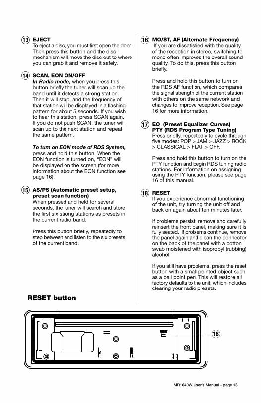
3. Push the panel mechanism back
into the housing so it is not protruding.
To do so, push the BOTTOM EDGE
down straight into the unit – do not
lift it! (Figure 7).
4. Immediately place the front panel
in its protective case for safe and
clean storage (Figure 8).
EON
EON
CONTENTS
MR1640W User’s Manual - page 1
U S E R ’ S M A N U A L
General and Tuner Controls
MR1640W User’s Manual - page 10 MR1640W User’s Manual - page 11
Wiring diagram
MR1640W User’s Manual - page 18
Troubleshooting
MR1640W User’s Manual - page 19
Specifications
MR1640W User’s Manual - page 20
MR1640W User’s Manual - page 4 MR1640W User’s Manual - page 5
Removing the head unit
Remote Control
MR1640W User’s Manual - page 14
General and Tuner Controls, continued
MR1640W User’s Manual - page 12 MR1640W User’s Manual - page 13
CD playback
MR1640W User’s Manual - page 15
MP3 disc playback
MR1640W User’s Manual - page 17
PTY Station Categories
MR1640W User’s Manual - page 6
Remote control installation
FLUSH MOUNT
MR1640W User’s Manual - page 7
Remote control installation, continued
MR1640W User’s Manual - page 16
RDS Radio functions
MR1640W User’s Manual - page 8
Remote control installation, continued
MR1640W User’s Manual - page 9
Remote control installation, continued
MR1640W User’s Manual - page 2
Head unit installation
MR2080W User’s Manual - page 3
Reinserting the front panelDetaching the front panel
MR1640 Marine MP3/CD Receiver Packing List
RESET button
Weather Band Tuning
Follow the wiring illustration below closely to obtain proper performance from your CDreceiver. Failure to make these connections properly may result in damage to your unitwhich will not be covered under your warranty.
This receiver contains a built-in high power four-channel amplifier. To use the built-inamplifier, connect the speaker wires as shown. To use the receiver as a head unit in a2CH, 4CH or 4CH-plus-subwoofer mobile audio system which includes an amplifier(s)or power subwoofer, use the RCA outputs to connect to the RCA inputs of your amplifier(s).
If you experience operation or performance problems with this product, compare yourinstallation with the electrical wiring diagram on the previous page. If problems persist,read the following troubleshooting tips which may help eliminate the problems.
Should you need to remove the head
unit, first remove and store the front
panel as described on the preceding
page.
After you have removed the front panel,
insert the removal keys supplied with
the head unit into the two removal slots
as shown in the drawing until you feel
a “click.” You can now use the levers
to pull the unit from the mounting
surface. (Figures 10 and 11).
Figure 11 Insert removal keys until “click” occurs,
keys to pull out head unit.
Please follow these general instructions toplay a music CD disc. On the column tothe right, you will find instructions for usingMP3 discs.
Please note that only some of thesefunctions are available on the remote control.
Loading a discPress down the latch on the disc door asshown in the figure below, and then pushit down to open the door.
Gently insert a disc into the disc slot untilyou feel it being drawn in by the playermechanism. If there is already a disc in theplayer, first press EJECT to eject it andremove it.
Playing a discThe disc will begin playing automatically. Ifyou wish to pause playback, pressPLAY/PAUSE, and press again to resumeplayback.
To start playback from the first track, pressPRESET 1. To select the next or last tentracks to play, press the +10 or -10 button.
Intro Scan functionThe Intro Scan function is a convenient wayto find a particular track. Press this buttonand the player will play the first few secondsof a song, and then skip to the next songand play a few seconds of that song. Thisprocess continues until you press the INTRObutton again, and the player will continueplaying that song.
Repeating a trackTo keep repeating the same track, pressthe REPEAT button. To cancel the repeatfunction, press again.
Random playPressing the RANDOM will cause the playerto play all the songs on the current disc inrandom order. Press again to cancel thisfunction.
When you insert an MP3 (or WMA) disc,the player will begin playback from the firsttrack in the directory.
However, MP3 discs can contain manymore tracks than audio CD’s, so you maywish to search for a particular track to play.There are three search methods available.
TRACK SEARCH MODE
In disc playback mode, press the BANDbutton once. The LCD will display the word“TRACK.”
To begin searching, press SELECT or theUP/DOWN button. Then press and holdthe UP or DOWN button to locate thedesired track, and press SELECT to beginplayback.
NAVIGATE THE CURRENT FOLDER
This mode permits you to navigate the filedirectory present on the disc.
To enter this mode, press BAND twice. Thedisplay will display “NAVIGA.” PressSELECT to enter this mode.
Use the UP and DOWN buttons to moveup and down the directory of folders andfiles on the disc. To enter a subfolder ,highlight it and press SELECT. You will thensee the directory of that subfolder and canselect tracks within it. So play a track,highlight it and push SELECT.
VIEWING MP3 FILE INFORMATION
Since many MP3 files are tagged withMusic/Artist/Album (ID3-TAG) information,you can see this as a list by pressing AS/PSrepeatedly.
The information will appear as a scrollingdisplay, including the folder and file nameas well as the ID3-TAG information.
Please note that if this information is notpresent in ID3-TAG version 1.0 or 2.0 format,it will not be displayed.
Push down on latch torelease it, then push it down toopen the door.
FRONT AUDIO OUTPUTSBROWN CABLE
REAR AUDIO OUTPUTSGREY CABLE
RIGHT CH (RED)
LEFT CH (WHITE)
RIGHT CH (RED)
LEFT CH (WHITE)
ISO CONVERSIONCONNECTOR
OPTIONAL POWER AMPLIFIER
SPEAKER IMPEDANCE
MINIMUM 4 OHMS!
SPEAKER IMPEDANCE
MINIMUM 4 OHMS!
Place O-ring in groove on rear surface of flange of cup.
Follow these steps for a successful
installation:
1. Select the proper location which
accomodates the 3.45” overall
diameter, and mark its centerpoint.
2. Drill a hole with diameter of 3.2”-
3.3” (82-84mm). It is very important
that the hole does not exceed 3.3”.TA (Traffic Announcement)Many FM stations offer trafficannouncements in addition to their regularprogramming.
If you enable the TA function by pressingthe TA button, when this station broadcastsa traffic advisory, the radio’s RDS tuner willautomatically interrupt the regular programand play the alert. When the alert is finished,normal play of the broadcast will resume.
The TA function will also interrupt CD andMP3 playback temporarily if the EON featurehas been enabled (see below).
There are some other settings for TAbehavior that you can change. See theSELECT instructions on page 9 for moreinformation.
PTY (Program type)A number of RDS stations can be selectedby the type of program they broadcast, i.e.news, sport or classical music.
Press and hold the PTY button to cause thetuner to switch to RDS PTY type tuning. If atany time you wish to return to normal tuningmode, press and hold again.
When you have entered PTY mode, thedisplay will show “PTY” indicating that themode is enabled, and the name of the firstprogram type, “NEWS.”
To view other PTY categories, use theUP/DOWN buttons (a list of these categoriesis shown on the next page). To select thecategory, highlight it and press SELECT. Ifthere is no station found in that category, thedisplay will show “NONE PTY” and the radiowill return to normal mode.
3. Place the O-ring provided in the
groove on the rear surface of the flange
of the mounting cup.
4. Insert mounting arms fully into
mounting tube.
Mounting arms
Mounting tube
5. Insert mounting screws provided
through the slots in the cup and into
the threaded holes in the mounting
arms. Do not tighten more than a few
turns.
6. Insert this assembly fully into the
hole you have cut so that the flange
rests on the the mounting surface.
Be sure the cup is oriented with
arrow next to the word TOP is
pointing UP or your remote will be
turned when it is installed!
Insert the cup assembly fully into
the hole you have cut.
1. Place the mounting cup in the
location you wish to install it.
Using screws of suitable size and type
for your application, attach the cup to
the mounting surface. If necessary,
drill pilot holes for the screws first.
3. Press the cable into the curved
groove on the back of the remote
housing. Feed the cable end thru the
relief hole at the BACK of the cup OR
the bottom of the cup.
Be sure the cup is oriented with
arrow next to the word TOP is
pointing UP or your remote will be
turned when it is installed!
6. Grasp and turn the remote to the right
until it is in the correct position.
9. Press the cable into the curved
groove on the back of the remote
housing. Feed the cable end thru the
relief hole at the back of the cup.
10. Hold the remote in front of the cup
with the top up, and as you hold it, rotate
it about 20º counterclockwise.
11. Insert the remote control fully into the
cup so that the mounting hooks penetrate
the slots in the back of the cup.
If you feel resistance when you insert the
remote into the cup, pull the remote
housing and check that the cable has been
pressed into the curved slot, as described
in Step 2).
12. Grasp and turn the remote to the right
until it is in the correct position.
5. Insert the remote control fully into
the cup so that the mounting hooks
go through the slots in the back of the
cup.
If your installation is one in which the
cable is exiting out the bottom of the
housing (NOT the back), as you insert
the remote module pull the cable down
gently so it does not interfere with the
insertion of the remote into the cup.
4. Hold the remote in front of the cup
with the top up, and as you hold it,
rotate it about 20º counterclockwise.
2. If you are going to run the cable into
a hole in the mounting surface, drill a
hole of at least 9/16” (15mm) so that
you can pass the remote cable
connector through it.
If you are going to run the cable out
the bottom relief hole and out along
the mounting surface, skip this step.
If you feel resistance when you insert
the remote into the cup, pull the remote
housing out and check that the cable
has been pressed into the curved slot,
as described in Step 3).
To ensure that the installation
meets the IPX5 Waterproof
Standard, please follow these steps
carefully.
1. Remove the transport screws from
the top of the enclosure before
beginning the installation.
Fig 1 Remove transport screws
2. Place the two pieces of plastic film
provided over the two screw holes to
prevent water penetration.
Figure 2 Apply plastic film to seal screw holes
Figure 3 Bending the support tabs
Figure 9 Insert one end of the panel into the opening
in the main unit. Then push the other end of the
panel into main unit until you hear a “click”
1. Insert one side of the panel fully
into the opening in the main unit.
2. Then push the other end of the
front panel into the main body. You
should hear a “click.” (Figure 9)
NOTE: If the panel fails to lock into
position properly, the function of
some controls may be impaired,
and some segments of the display
may not become illuminated. If this
occurs, press RELEASE and reinstall
the front panel.
1. Press the RELEASE button to
release the panel from the right side
of the head unit (Figure 5).
2. Press the panel release latch on
the front edge of the lower surface of
faceplate, and at the same time pull
the panel forward to disengage it from
the main unit. (Figure 6).
Figure 5 Press RELEASE to release the front panel
RELEASE button
Figure 8 Place the front panel in its protective case
PUSH HERE in this direction
Figure 10 Slots for removal keys
Removal key slots
Before installing your new CD Receiver, please unpack the contents and check
that your package contains the following items:
RDS EON function settingThe RDS EON system extends thefunctionality of the TA sensing to a widerrange of traffic announcements from bothlocal and national sources. It also allows theunit to interrupt disc playback with theseannouncements. In addition, it will play theseannouncements (at normal listening level)even if the audio has been muted.
(To set this level, see instructions on page9 for setting V-PGM level).
To enable the EON function, press and holdthe SCAN button. Press again to disable it.
With EON enabled, when a trafficannouncement is broadcast, the radio willswitch automatically to TA mode, and “TP”(Traffic Program) will be displayed.
2 Head unit installation
4 Detaching the front panel
5 Removing the head unit
6 Remote control installationFlush mount
6 Remote control installationSurface mount
10 General and tuner controls
14 Remote control
15 CD Playback
15 MP3 playback
16 RDS radio functions
16 PTY station categories
17 Weather band tuning
18 Wiring diagram
19 Troubleshooting
20 Specifications
Congratulations on your
purchase of a Marine
Weather Band MP3/CD
Receiver.
It has been designed, engineered
and manufactured to bring you
the highest level of performance
and quality, and will afford you
years of listening pleasure.
Thank you for making
Marine your choice for
marine audio entertainment!
page
RDS EuropeanFrequency Model SYMPTOM CAUSE REMEDY
AS/PS (Automatic preset setup,preset scan function)
When pressed and held for severalseconds, the tuner will search and storethe first six strong stations as presets inthe current radio band.
Press this button briefly, repeatedly tostep between and listen to the six presetsof the current band.
15
• Beep (when you press a button): ON/OFF
• Clock On (determines if clock will bedisplayed when radio is turned off):ON/OFF
• LCD1/2 (LCD brightness level): 1/2
RDS Radio Settings• SEEK/RDS ALLThis setting determines the behavior ofthe radio SEEK function when RDS tuningmode. If ALL is selected, the SEEKfunction will stop at both RDS and non-RDS stations. Otherwise, it will only seekRDS stations. RDS/ALL
• TA (Traffic Alert) SEEK/ALARMWhen TA mode is on, the radio monitorsthe Public Information channel which ispiggy-backed on the FM channel you arecurrently enjoying. If such a channel is notdetected or is weak the tuner will SEEKanother PI channel and monitor it.( Thisis the TA SEEK setting).
If ALARM setting is chosen, if a signal isinsufficiently strong, instead of monitoringan alternate station for PI information, theradio will produce a double beep (alarm)and silence itself, and display “LOST TPTA.” TA SEEK/ALARM
• TA VOLUMEThis setting determines the volume levelof the Traffic Alerts as they play.0-40 (18 is default)
• REG ON/OFFThis setting determines the behavior ofthe radio reception when AF (AlternateFrequency) mode is on. The AF systemcontinuously monitors the signal strengthof a station and compares it with otherstations on the same network. If anotherstation is stronger, it changes to thatstation.
Since sometimes in different regionsstations on the same network will playdifferent programs, the AF system caninterrupt the current program. If REG ONis selected, the station will check if theprograms are the same, and if not, the TAsystem will not change the station.REG OFF/ON
EQ (Preset Equalizer Curves)PTY (RDS Program Type Tuning)Press briefly, repeatedly to cycle throughfive modes: POP > JAM > JAZZ > ROCK> CLASSICAL > FLAT > OFF.
Press and hold this button to turn on thePTY function and begin RDS tuning radiostations. For information on assigningusing the PTY function, please see page16 of this manual.
17
SCAN, EON ON/OFF
In Radio mode, when you press thisbutton briefly the tuner will scan up theband until it detects a strong station.Then it will stop, and the frequency ofthat station will be displayed in a flashingpattern for about 5 seconds. If you wishto hear this station, press SCAN again.If you do not push SCAN, the tuner willscan up to the next station and repeatthe same pattern.
14
To turn on EON mode of RDS System,press and hold this button. When theEON function is turned on, “EON” willbe displayed on the screen (for moreinformation about the EON function seepage 16).
MO/ST, AF (Alternate Frequency) If you are dissatisfied with the qualityof the reception in stereo, switching tomono often improves the overall soundquality. To do this, press this buttonbriefly.
Press and hold this button to turn onthe RDS AF function, which comparesthe signal strength of the current stationwith others on the same network andchanges to improve reception. See page16 for more information.
16EJECTTo eject a disc, you must first open the door.Then press this button and the discmechanism will move the disc out to whereyou can grab it and remove it safely.
13
RESETIf you experience abnormal functioningof the unit, try turning the unit off andback on again about ten minutes later.
If problems persist, remove and carefullyreinsert the front panel, making sure it isfully seated. If problems continue, removethe panel again and clean the connectoron the back of the panel with a cottonswab moistened with isopropyl (rubbing)alcohol.
If you still have problems, press the resetbutton with a small pointed object suchas a ball point pen. This will restore allfactory defaults to the unit, which includesclearing your radio presets.
18
This list shows the PTY program types in theorder presented in the radio display:
NEWS
AFFAIRS
INFORMATION
SPORTS
EDUCATION
DRAMA
CULTURE
SCIENCE
VARIETY
POP MUSIC
ROCK MUSIC
EASY LISTENING MUSIC
LIGHT MUSIC
CLASSICAL MUSIC
OTHER MUSIC
WEATHER
FINANCE
CHILDREN
SOCIAL
RELIGIOUS
PHONE IN
TRAVEL
LEISURE
JAZZ MUSIC
COUNTRY MUSIC
NATIONAL MUSIC
OLDIES MUSIC
FOLK MUSIC
DOCUMENTARY
ALERT TEST
ALARM TEST
3. Insert and tighten the “headless”
support screw into the back of the
head unit where shown.
4. Insert the mounting case for the
head unit into the dashboard. Inspect
the dashboard material to determine
its approximate thickness. Select the
appropriate support tabs and bend
them outward to secure the bracket
in place (Figure 3).
5. Bend the backstrap to conform to
the mounting case and the dashboard
surface to which you plan to secure
the backstrap (Figure 4). Slide one of
the utility holes on the backstrap onto
the support screw and fasten it with
the spring washer and nut provided.
6. Using the 5 x 25mm screw and the
plain washer, secure the backstrap to
the dashboard surface as shown in
the diagram. Tighten, secure, and
check the overall mounting to be sure
it is safe and will not release in an
emergency stop or other sudden
movement of the vehicle.
Weather band listening is available usingTUNE/TRK buttons or the radio presets.
To hear the weather band stations, press theBAND button until the weather band isdisplayed.
The six preset buttons are assigned to thefollowing frequencies and cannot be changed:
PRESET # Frequency, MHz
1 162.40
2 162.43
3 162.45
4 162.47
5 162.50
6 162.53
if you wish to tune to the 7th available frequency,162.55MHz, use the TUNE/TRK buttons tolocate it.
Please note that in Weather Band, the followingbuttons are not operable:
SCANAS/PS
Mounting
surface
Drill a 9/16”
(15mm) or
larger hole to
allow cable to
pass through
mounting
surface.
Intallation with cable going
into hole in mounting surface.
Intallation with cable running out on top
of mounting surface.
Figure 6 Press release latch on on the lower surfaceof the front edge of the panel and pull the panel until itis free of the head unit.
Figure 7 Push the panel mechanism back in
Slide the screws out to
extend the mounting arms
so that they reach behind
the mounting surface.
Insert the mounting screws through
the cup into the threaded holes
in the mounting arms
Hold the remote in front of
the cup, turned about
20º counterclockwise.
- OR -
18

3. Push the panel mechanism back
into the housing so it is not protruding.
To do so, push the BOTTOM EDGE
down straight into the unit – do not
lift it! (Figure 7).
4. Immediately place the front panel
in its protective case for safe and
clean storage (Figure 8).
EON
EON
SCAN
BAND
MUTE
TUNE • TRACK
MODE
VOLUME
MARINE REMOTE COMMANDER
CONTENTS
MR1640W User’s Manual - page 1
U S E R ’ S M A N U A L
General and Tuner Controls
MR1640W User’s Manual - page 10 MR1640W User’s Manual - page 11
Wiring diagram
MR1640W User’s Manual - page 18
Troubleshooting
MR1640W User’s Manual - page 19
Specifications
MR1640W User’s Manual - page 20
MR1640W User’s Manual - page 4 MR1640W User’s Manual - page 5
Removing the head unit
Remote Control
MR1640W User’s Manual - page 14
General and Tuner Controls, continued
MR1640W User’s Manual - page 12 MR1640W User’s Manual - page 13
CD playback
MR1640W User’s Manual - page 15
MP3 disc playback
MR1640W User’s Manual - page 17
PTY Station Categories
MR1640W User’s Manual - page 6
Remote control installation
FLUSH MOUNT
MR1640W User’s Manual - page 7
Remote control installation, continued
MR1640W User’s Manual - page 16
RDS Radio functions
MR1640W User’s Manual - page 8
Remote control installation, continued
MR1640W User’s Manual - page 9
Remote control installation, continued
MR1640W User’s Manual - page 2
Head unit installation
MR2080W User’s Manual - page 3
Reinserting the front panelDetaching the front panel
MR1640 Marine MP3/CD Receiver Packing List
RESET button
Weather Band Tuning
Follow the wiring illustration below closely to obtain proper performance from your CDreceiver. Failure to make these connections properly may result in damage to your unitwhich will not be covered under your warranty.
This receiver contains a built-in high power four-channel amplifier. To use the built-inamplifier, connect the speaker wires as shown. To use the receiver as a head unit in a2CH, 4CH or 4CH-plus-subwoofer mobile audio system which includes an amplifier(s)or power subwoofer, use the RCA outputs to connect to the RCA inputs of your amplifier(s).
If you experience operation or performance problems with this product, compare yourinstallation with the electrical wiring diagram on the previous page. If problems persist,read the following troubleshooting tips which may help eliminate the problems.
Should you need to remove the head
unit, first remove and store the front
panel as described on the preceding
page.
After you have removed the front panel,
insert the removal keys supplied with
the head unit into the two removal slots
as shown in the drawing until you feel
a “click.” You can now use the levers
to pull the unit from the mounting
surface. (Figures 10 and 11).
Figure 11 Insert removal keys until “click” occurs,
keys to pull out head unit.
Please follow these general instructions toplay a music CD disc. On the column tothe right, you will find instructions for usingMP3 discs.
Please note that only some of thesefunctions are available on the remote control.
Loading a discPress down the latch on the disc door asshown in the figure below, and then pushit down to open the door.
Gently insert a disc into the disc slot untilyou feel it being drawn in by the playermechanism. If there is already a disc in theplayer, first press EJECT to eject it andremove it.
Playing a discThe disc will begin playing automatically. Ifyou wish to pause playback, pressPLAY/PAUSE, and press again to resumeplayback.
To start playback from the first track, pressPRESET 1. To select the next or last tentracks to play, press the +10 or -10 button.
Intro Scan functionThe Intro Scan function is a convenient wayto find a particular track. Press this buttonand the player will play the first few secondsof a song, and then skip to the next songand play a few seconds of that song. Thisprocess continues until you press the INTRObutton again, and the player will continueplaying that song.
Repeating a trackTo keep repeating the same track, pressthe REPEAT button. To cancel the repeatfunction, press again.
Random playPressing the RANDOM will cause the playerto play all the songs on the current disc inrandom order. Press again to cancel thisfunction.
When you insert an MP3 (or WMA) disc,the player will begin playback from the firsttrack in the directory.
However, MP3 discs can contain manymore tracks than audio CD’s, so you maywish to search for a particular track to play.There are three search methods available.
TRACK SEARCH MODE
In disc playback mode, press the BANDbutton once. The LCD will display the word“TRACK.”
To begin searching, press SELECT or theUP/DOWN button. Then press and holdthe UP or DOWN button to locate thedesired track, and press SELECT to beginplayback.
NAVIGATE THE CURRENT FOLDER
This mode permits you to navigate the filedirectory present on the disc.
To enter this mode, press BAND twice. Thedisplay will display “NAVIGA.” PressSELECT to enter this mode.
Use the UP and DOWN buttons to moveup and down the directory of folders andfiles on the disc. To enter a subfolder ,highlight it and press SELECT. You will thensee the directory of that subfolder and canselect tracks within it. So play a track,highlight it and push SELECT.
VIEWING MP3 FILE INFORMATION
Since many MP3 files are tagged withMusic/Artist/Album (ID3-TAG) information,you can see this as a list by pressing AS/PSrepeatedly.
The information will appear as a scrollingdisplay, including the folder and file nameas well as the ID3-TAG information.
Please note that if this information is notpresent in ID3-TAG version 1.0 or 2.0 format,it will not be displayed.
Push down on latch torelease it, then push it down toopen the door.
FRONT AUDIO OUTPUTSBROWN CABLE
REAR AUDIO OUTPUTSGREY CABLE
RIGHT CH (RED)
LEFT CH (WHITE)
RIGHT CH (RED)
LEFT CH (WHITE)
ISO CONVERSIONCONNECTOR
OPTIONAL POWER AMPLIFIER
SPEAKER IMPEDANCE
MINIMUM 4 OHMS!
SPEAKER IMPEDANCE
MINIMUM 4 OHMS!
Place O-ring in groove on rear surface of flange of cup.
Follow these steps for a successful
installation:
1. Select the proper location which
accomodates the 3.45” overall
diameter, and mark its centerpoint.
2. Drill a hole with diameter of 3.2”-
3.3” (82-84mm). It is very important
that the hole does not exceed 3.3”.TA (Traffic Announcement)Many FM stations offer trafficannouncements in addition to their regularprogramming.
If you enable the TA function by pressingthe TA button, when this station broadcastsa traffic advisory, the radio’s RDS tuner willautomatically interrupt the regular programand play the alert. When the alert is finished,normal play of the broadcast will resume.
The TA function will also interrupt CD andMP3 playback temporarily if the EON featurehas been enabled (see below).
There are some other settings for TAbehavior that you can change. See theSELECT instructions on page 9 for moreinformation.
PTY (Program type)A number of RDS stations can be selectedby the type of program they broadcast, i.e.news, sport or classical music.
Press and hold the PTY button to cause thetuner to switch to RDS PTY type tuning. If atany time you wish to return to normal tuningmode, press and hold again.
When you have entered PTY mode, thedisplay will show “PTY” indicating that themode is enabled, and the name of the firstprogram type, “NEWS.”
To view other PTY categories, use theUP/DOWN buttons (a list of these categoriesis shown on the next page). To select thecategory, highlight it and press SELECT. Ifthere is no station found in that category, thedisplay will show “NONE PTY” and the radiowill return to normal mode.
3. Place the O-ring provided in the
groove on the rear surface of the flange
of the mounting cup.
4. Insert mounting arms fully into
mounting tube.
Mounting arms
Mounting tube
5. Insert mounting screws provided
through the slots in the cup and into
the threaded holes in the mounting
arms. Do not tighten more than a few
turns.
6. Insert this assembly fully into the
hole you have cut so that the flange
rests on the the mounting surface.
Be sure the cup is oriented with
arrow next to the word TOP is
pointing UP or your remote will be
turned when it is installed!
Insert the cup assembly fully into
the hole you have cut.
1. Place the mounting cup in the
location you wish to install it.
Using screws of suitable size and type
for your application, attach the cup to
the mounting surface. If necessary,
drill pilot holes for the screws first.
3. Press the cable into the curved
groove on the back of the remote
housing. Feed the cable end thru the
relief hole at the BACK of the cup OR
the bottom of the cup.
Be sure the cup is oriented with
arrow next to the word TOP is
pointing UP or your remote will be
turned when it is installed!
6. Grasp and turn the remote to the right
until it is in the correct position.
9. Press the cable into the curved
groove on the back of the remote
housing. Feed the cable end thru the
relief hole at the back of the cup.
10. Hold the remote in front of the cup
with the top up, and as you hold it, rotate
it about 20º counterclockwise.
11. Insert the remote control fully into the
cup so that the mounting hooks penetrate
the slots in the back of the cup.
If you feel resistance when you insert the
remote into the cup, pull the remote
housing and check that the cable has been
pressed into the curved slot, as described
in Step 2).
12. Grasp and turn the remote to the right
until it is in the correct position.
5. Insert the remote control fully into
the cup so that the mounting hooks
go through the slots in the back of the
cup.
If your installation is one in which the
cable is exiting out the bottom of the
housing (NOT the back), as you insert
the remote module pull the cable down
gently so it does not interfere with the
insertion of the remote into the cup.
4. Hold the remote in front of the cup
with the top up, and as you hold it,
rotate it about 20º counterclockwise.
2. If you are going to run the cable into
a hole in the mounting surface, drill a
hole of at least 9/16” (15mm) so that
you can pass the remote cable
connector through it.
If you are going to run the cable out
the bottom relief hole and out along
the mounting surface, skip this step.
If you feel resistance when you insert
the remote into the cup, pull the remote
housing out and check that the cable
has been pressed into the curved slot,
as described in Step 3).
To ensure that the installation
meets the IPX5 Waterproof
Standard, please follow these steps
carefully.
1. Remove the transport screws from
the top of the enclosure before
beginning the installation.
Fig 1 Remove transport screws
2. Place the two pieces of plastic film
provided over the two screw holes to
prevent water penetration.
Figure 2 Apply plastic film to seal screw holes
Figure 3 Bending the support tabs
Figure 9 Insert one end of the panel into the opening
in the main unit. Then push the other end of the
panel into main unit until you hear a “click”
1. Insert one side of the panel fully
into the opening in the main unit.
2. Then push the other end of the
front panel into the main body. You
should hear a “click.” (Figure 9)
NOTE: If the panel fails to lock into
position properly, the function of
some controls may be impaired,
and some segments of the display
may not become illuminated. If this
occurs, press RELEASE and reinstall
the front panel.
1. Press the RELEASE button to
release the panel from the right side
of the head unit (Figure 5).
2. Press the panel release latch on
the front edge of the lower surface of
faceplate, and at the same time pull
the panel forward to disengage it from
the main unit. (Figure 6).
Figure 5 Press RELEASE to release the front panel
RELEASE button
Figure 8 Place the front panel in its protective case
PUSH HERE in this direction
Figure 10 Slots for removal keys
Removal key slots
Before installing your new CD Receiver, please unpack the contents and check
that your package contains the following items:
RDS EON function settingThe RDS EON system extends thefunctionality of the TA sensing to a widerrange of traffic announcements from bothlocal and national sources. It also allows theunit to interrupt disc playback with theseannouncements. In addition, it will play theseannouncements (at normal listening level)even if the audio has been muted.
(To set this level, see instructions on page9 for setting V-PGM level).
To enable the EON function, press and holdthe SCAN button. Press again to disable it.
With EON enabled, when a trafficannouncement is broadcast, the radio willswitch automatically to TA mode, and “TP”(Traffic Program) will be displayed.
2Head unit installation
4Detaching the front panel
5Removing the head unit
6Remote control installationFlush mount
6Remote control installationSurface mount
10General and tuner controls
14Remote control
15CD Playback
15MP3 playback
16RDS radio functions
16PTY station categories
17Weather band tuning
18Wiring diagram
19Troubleshooting
20Specifications
Congratulations on your
purchase of a Marine
Weather Band MP3/CD
Receiver.
It has been designed, engineered
and manufactured to bring you
the highest level of performance
and quality, and will afford you
years of listening pleasure.
Thank you for making
Marine your choice for
marine audio entertainment!
page
RDS EuropeanFrequency Model SYMPTOM CAUSE REMEDY
POWERUse to turn CD Receiver ON or OFF.
1
VOLUME Use to increase or decreasevolume level.
7
MODEPress to choose desired audio source:RADIO > CD > AUX1 IN > AUX (frontpanel aux input)
2
• Beep (when you press a button): ON/OFF
• Clock On (determines if clock will bedisplayed when radio is turned off):ON/OFF
• LCD1/2 (LCD brightness level): 1/2
RDS Radio Settings• SEEK/RDS ALLThis setting determines the behavior ofthe radio SEEK function when RDS tuningmode. If ALL is selected, the SEEKfunction will stop at both RDS and non-RDS stations. Otherwise, it will only seekRDS stations. RDS/ALL
• TA (Traffic Alert) SEEK/ALARMWhen TA mode is on, the radio monitorsthe Public Information channel which ispiggy-backed on the FM channel you arecurrently enjoying. If such a channel is notdetected or is weak the tuner will SEEKanother PI channel and monitor it.( Thisis the TA SEEK setting).
If ALARM setting is chosen, if a signal isinsufficiently strong, instead of monitoringan alternate station for PI information, theradio will produce a double beep (alarm)and silence itself, and display “LOST TPTA.” TA SEEK/ALARM
• TA VOLUMEThis setting determines the volume levelof the Traffic Alerts as they play.0-40 (18 is default)
• REG ON/OFFThis setting determines the behavior ofthe radio reception when AF (AlternateFrequency) mode is on. The AF systemcontinuously monitors the signal strengthof a station and compares it with otherstations on the same network. If anotherstation is stronger, it changes to thatstation.
Since sometimes in different regionsstations on the same network will playdifferent programs, the AF system caninterrupt the current program. If REG ONis selected, the station will check if theprograms are the same, and if not, the TAsystem will not change the station.REG OFF/ON
BANDPress briefly, repeatedly to cyclebetween the radio bands:
FM1 > FM2 > FM3 > AM1 > AM2 >WB (Weather Band)
3
SCAN/EON ON/OFF
In Radio Mode, when you pressthis button briefly the tuner willscan up the band until it detectsa strong station. Then it will stop,and the frequency of that stationwill be displayed in a flashingpattern for about 5 seconds. Ifyou wish to hear this station,press SCAN again. If you do notpush SCAN, the tuner will scanup to the next station and repeatthe same pattern.
To turn on EON mode of RDSSystem, press and hold thisbutton. When the EON functionis turned on, “EON” will bedisplayed on the screen (for moreinformation about the EONfunction see page 14).
4
PLAY/PAUSEDiscs will begin playback automaticallyupon insertion. To pause playback, pressthis button. Press again to resumeplayback.
6
MUTE
Press and hold this button to silencethe audio. Press again to restore theprevious audio volume level.
8
To turn on EON mode of RDS System,press and hold this button. When theEON function is turned on, “EON” willbe displayed on the screen (for moreinformation about the EON function seepage 16).
5
1
TUNE/TRACKIn Radio Mode, press and release toactivate automatic seek function(”AUTO” will appear on display). Pressand hold to engage manual tuningmode (”MANUL” will appear ondisplay).
In CD Mode, press and release toadvance to the next track or to returnto the beginning of the current track(track number will be displayed). Pressand hold to fast forward or reverse.Play will begin at the point when yourelease the button.
5 ( and )
3
6 7 8
2
This list shows the PTY program types in theorder presented in the radio display:
NEWS
AFFAIRS
INFORMATION
SPORTS
EDUCATION
DRAMA
CULTURE
SCIENCE
VARIETY
POP MUSIC
ROCK MUSIC
EASY LISTENING MUSIC
LIGHT MUSIC
CLASSICAL MUSIC
OTHER MUSIC
WEATHER
FINANCE
CHILDREN
SOCIAL
RELIGIOUS
PHONE IN
TRAVEL
LEISURE
JAZZ MUSIC
COUNTRY MUSIC
NATIONAL MUSIC
OLDIES MUSIC
FOLK MUSIC
DOCUMENTARY
ALERT TEST
ALARM TEST
3. Insert and tighten the “headless”
support screw into the back of the
head unit where shown.
4. Insert the mounting case for the
head unit into the dashboard. Inspect
the dashboard material to determine
its approximate thickness. Select the
appropriate support tabs and bend
them outward to secure the bracket
in place (Figure 3).
5. Bend the backstrap to conform to
the mounting case and the dashboard
surface to which you plan to secure
the backstrap (Figure 4). Slide one of
the utility holes on the backstrap onto
the support screw and fasten it with
the spring washer and nut provided.
6. Using the 5 x 25mm screw and the
plain washer, secure the backstrap to
the dashboard surface as shown in
the diagram. Tighten, secure, and
check the overall mounting to be sure
it is safe and will not release in an
emergency stop or other sudden
movement of the vehicle.
Weather band listening is available usingTUNE/TRK buttons or the radio presets.
To hear the weather band stations, press theBAND button until the weather band isdisplayed.
The six preset buttons are assigned to thefollowing frequencies and cannot be changed:
PRESET # Frequency, MHz
1 162.40
2 162.43
3 162.45
4 162.47
5 162.50
6 162.53
if you wish to tune to the 7th available frequency,162.55MHz, use the TUNE/TRK buttons tolocate it.
Please note that in Weather Band, the followingbuttons are not operable:
SCANAS/PS
Mounting
surface
Drill a 9/16”
(15mm) or
larger hole to
allow cable to
pass through
mounting
surface.
Intallation with cable going
into hole in mounting surface.
Intallation with cable running out on top
of mounting surface.
4
Figure 6 Press release latch on on the lower surfaceof the front edge of the panel and pull the panel until itis free of the head unit.
Figure 7 Push the panel mechanism back in
Slide the screws out to
extend the mounting arms
so that they reach behind
the mounting surface.
Insert the mounting screws through
the cup into the threaded holes
in the mounting arms
Hold the remote in front of
the cup, turned about
20º counterclockwise.
- OR -
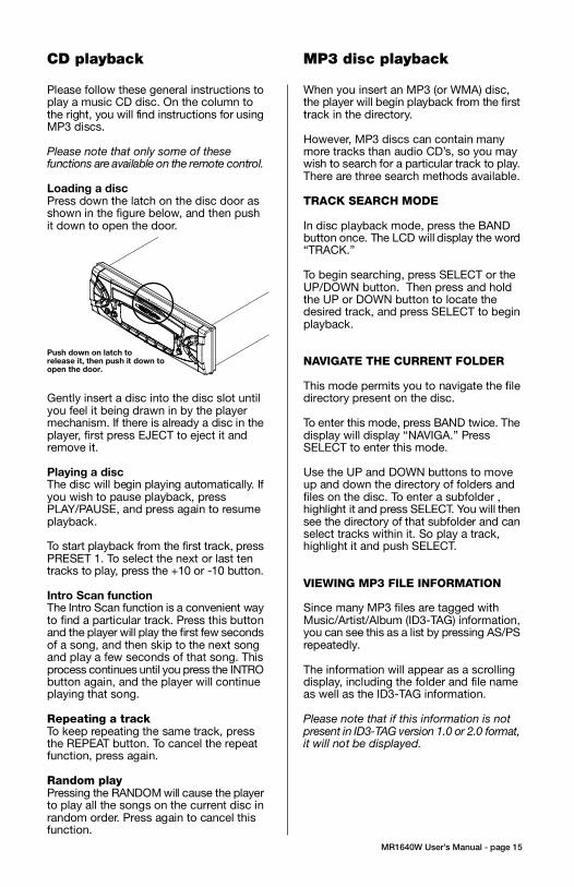
3. Push the panel mechanism back
into the housing so it is not protruding.
To do so, push the BOTTOM EDGE
down straight into the unit – do not
lift it! (Figure 7).
4. Immediately place the front panel
in its protective case for safe and
clean storage (Figure 8).
EON
EON
CONTENTS
MR1640W User’s Manual - page 1
U S E R ’ S M A N U A L
General and Tuner Controls
MR1640W User’s Manual - page 10 MR1640W User’s Manual - page 11
Wiring diagram
MR1640W User’s Manual - page 18
Troubleshooting
MR1640W User’s Manual - page 19
Specifications
MR1640W User’s Manual - page 20
MR1640W User’s Manual - page 4 MR1640W User’s Manual - page 5
Removing the head unit
Remote Control
MR1640W User’s Manual - page 14
General and Tuner Controls, continued
MR1640W User’s Manual - page 12 MR1640W User’s Manual - page 13
CD playback
MR1640W User’s Manual - page 15
MP3 disc playback
MR1640W User’s Manual - page 17
PTY Station Categories
MR1640W User’s Manual - page 6
Remote control installation
FLUSH MOUNT
MR1640W User’s Manual - page 7
Remote control installation, continued
MR1640W User’s Manual - page 16
RDS Radio functions
MR1640W User’s Manual - page 8
Remote control installation, continued
MR1640W User’s Manual - page 9
Remote control installation, continued
MR1640W User’s Manual - page 2
Head unit installation
MR2080W User’s Manual - page 3
Reinserting the front panelDetaching the front panel
MR1640 Marine MP3/CD Receiver Packing List
RESET button
Weather Band Tuning
Follow the wiring illustration below closely to obtain proper performance from your CDreceiver. Failure to make these connections properly may result in damage to your unitwhich will not be covered under your warranty.
This receiver contains a built-in high power four-channel amplifier. To use the built-inamplifier, connect the speaker wires as shown. To use the receiver as a head unit in a2CH, 4CH or 4CH-plus-subwoofer mobile audio system which includes an amplifier(s)or power subwoofer, use the RCA outputs to connect to the RCA inputs of your amplifier(s).
If you experience operation or performance problems with this product, compare yourinstallation with the electrical wiring diagram on the previous page. If problems persist,read the following troubleshooting tips which may help eliminate the problems.
Should you need to remove the head
unit, first remove and store the front
panel as described on the preceding
page.
After you have removed the front panel,
insert the removal keys supplied with
the head unit into the two removal slots
as shown in the drawing until you feel
a “click.” You can now use the levers
to pull the unit from the mounting
surface. (Figures 10 and 11).
Figure 11 Insert removal keys until “click” occurs,
keys to pull out head unit.
Please follow these general instructions toplay a music CD disc. On the column tothe right, you will find instructions for usingMP3 discs.
Please note that only some of thesefunctions are available on the remote control.
Loading a discPress down the latch on the disc door asshown in the figure below, and then pushit down to open the door.
Gently insert a disc into the disc slot untilyou feel it being drawn in by the playermechanism. If there is already a disc in theplayer, first press EJECT to eject it andremove it.
Playing a discThe disc will begin playing automatically. Ifyou wish to pause playback, pressPLAY/PAUSE, and press again to resumeplayback.
To start playback from the first track, pressPRESET 1. To select the next or last tentracks to play, press the +10 or -10 button.
Intro Scan functionThe Intro Scan function is a convenient wayto find a particular track. Press this buttonand the player will play the first few secondsof a song, and then skip to the next songand play a few seconds of that song. Thisprocess continues until you press the INTRObutton again, and the player will continueplaying that song.
Repeating a trackTo keep repeating the same track, pressthe REPEAT button. To cancel the repeatfunction, press again.
Random playPressing the RANDOM will cause the playerto play all the songs on the current disc inrandom order. Press again to cancel thisfunction.
When you insert an MP3 (or WMA) disc,the player will begin playback from the firsttrack in the directory.
However, MP3 discs can contain manymore tracks than audio CD’s, so you maywish to search for a particular track to play.There are three search methods available.
TRACK SEARCH MODE
In disc playback mode, press the BANDbutton once. The LCD will display the word“TRACK.”
To begin searching, press SELECT or theUP/DOWN button. Then press and holdthe UP or DOWN button to locate thedesired track, and press SELECT to beginplayback.
NAVIGATE THE CURRENT FOLDER
This mode permits you to navigate the filedirectory present on the disc.
To enter this mode, press BAND twice. Thedisplay will display “NAVIGA.” PressSELECT to enter this mode.
Use the UP and DOWN buttons to moveup and down the directory of folders andfiles on the disc. To enter a subfolder ,highlight it and press SELECT. You will thensee the directory of that subfolder and canselect tracks within it. So play a track,highlight it and push SELECT.
VIEWING MP3 FILE INFORMATION
Since many MP3 files are tagged withMusic/Artist/Album (ID3-TAG) information,you can see this as a list by pressing AS/PSrepeatedly.
The information will appear as a scrollingdisplay, including the folder and file nameas well as the ID3-TAG information.
Please note that if this information is notpresent in ID3-TAG version 1.0 or 2.0 format,it will not be displayed.
Push down on latch torelease it, then push it down toopen the door.
FRONT AUDIO OUTPUTSBROWN CABLE
REAR AUDIO OUTPUTSGREY CABLE
RIGHT CH (RED)
LEFT CH (WHITE)
RIGHT CH (RED)
LEFT CH (WHITE)
ISO CONVERSIONCONNECTOR
OPTIONAL POWER AMPLIFIER
SPEAKER IMPEDANCE
MINIMUM 4 OHMS!
SPEAKER IMPEDANCE
MINIMUM 4 OHMS!
Place O-ring in groove on rear surface of flange of cup.
Follow these steps for a successful
installation:
1. Select the proper location which
accomodates the 3.45” overall
diameter, and mark its centerpoint.
2. Drill a hole with diameter of 3.2”-
3.3” (82-84mm). It is very important
that the hole does not exceed 3.3”.TA (Traffic Announcement)Many FM stations offer trafficannouncements in addition to their regularprogramming.
If you enable the TA function by pressingthe TA button, when this station broadcastsa traffic advisory, the radio’s RDS tuner willautomatically interrupt the regular programand play the alert. When the alert is finished,normal play of the broadcast will resume.
The TA function will also interrupt CD andMP3 playback temporarily if the EON featurehas been enabled (see below).
There are some other settings for TAbehavior that you can change. See theSELECT instructions on page 9 for moreinformation.
PTY (Program type)A number of RDS stations can be selectedby the type of program they broadcast, i.e.news, sport or classical music.
Press and hold the PTY button to cause thetuner to switch to RDS PTY type tuning. If atany time you wish to return to normal tuningmode, press and hold again.
When you have entered PTY mode, thedisplay will show “PTY” indicating that themode is enabled, and the name of the firstprogram type, “NEWS.”
To view other PTY categories, use theUP/DOWN buttons (a list of these categoriesis shown on the next page). To select thecategory, highlight it and press SELECT. Ifthere is no station found in that category, thedisplay will show “NONE PTY” and the radiowill return to normal mode.
3. Place the O-ring provided in the
groove on the rear surface of the flange
of the mounting cup.
4. Insert mounting arms fully into
mounting tube.
Mounting arms
Mounting tube
5. Insert mounting screws provided
through the slots in the cup and into
the threaded holes in the mounting
arms. Do not tighten more than a few
turns.
6. Insert this assembly fully into the
hole you have cut so that the flange
rests on the the mounting surface.
Be sure the cup is oriented with
arrow next to the word TOP is
pointing UP or your remote will be
turned when it is installed!
Insert the cup assembly fully into
the hole you have cut.
1. Place the mounting cup in the
location you wish to install it.
Using screws of suitable size and type
for your application, attach the cup to
the mounting surface. If necessary,
drill pilot holes for the screws first.
3. Press the cable into the curved
groove on the back of the remote
housing. Feed the cable end thru the
relief hole at the BACK of the cup OR
the bottom of the cup.
Be sure the cup is oriented with
arrow next to the word TOP is
pointing UP or your remote will be
turned when it is installed!
6. Grasp and turn the remote to the right
until it is in the correct position.
9. Press the cable into the curved
groove on the back of the remote
housing. Feed the cable end thru the
relief hole at the back of the cup.
10. Hold the remote in front of the cup
with the top up, and as you hold it, rotate
it about 20º counterclockwise.
11. Insert the remote control fully into the
cup so that the mounting hooks penetrate
the slots in the back of the cup.
If you feel resistance when you insert the
remote into the cup, pull the remote
housing and check that the cable has been
pressed into the curved slot, as described
in Step 2).
12. Grasp and turn the remote to the right
until it is in the correct position.
5. Insert the remote control fully into
the cup so that the mounting hooks
go through the slots in the back of the
cup.
If your installation is one in which the
cable is exiting out the bottom of the
housing (NOT the back), as you insert
the remote module pull the cable down
gently so it does not interfere with the
insertion of the remote into the cup.
4. Hold the remote in front of the cup
with the top up, and as you hold it,
rotate it about 20º counterclockwise.
2. If you are going to run the cable into
a hole in the mounting surface, drill a
hole of at least 9/16” (15mm) so that
you can pass the remote cable
connector through it.
If you are going to run the cable out
the bottom relief hole and out along
the mounting surface, skip this step.
If you feel resistance when you insert
the remote into the cup, pull the remote
housing out and check that the cable
has been pressed into the curved slot,
as described in Step 3).
To ensure that the installation
meets the IPX5 Waterproof
Standard, please follow these steps
carefully.
1. Remove the transport screws from
the top of the enclosure before
beginning the installation.
Fig 1 Remove transport screws
2. Place the two pieces of plastic film
provided over the two screw holes to
prevent water penetration.
Figure 2 Apply plastic film to seal screw holes
Figure 3 Bending the support tabs
Figure 9 Insert one end of the panel into the opening
in the main unit. Then push the other end of the
panel into main unit until you hear a “click”
1. Insert one side of the panel fully
into the opening in the main unit.
2. Then push the other end of the
front panel into the main body. You
should hear a “click.” (Figure 9)
NOTE: If the panel fails to lock into
position properly, the function of
some controls may be impaired,
and some segments of the display
may not become illuminated. If this
occurs, press RELEASE and reinstall
the front panel.
1. Press the RELEASE button to
release the panel from the right side
of the head unit (Figure 5).
2. Press the panel release latch on
the front edge of the lower surface of
faceplate, and at the same time pull
the panel forward to disengage it from
the main unit. (Figure 6).
Figure 5 Press RELEASE to release the front panel
RELEASE button
Figure 8 Place the front panel in its protective case
PUSH HERE in this direction
Figure 10 Slots for removal keys
Removal key slots
Before installing your new CD Receiver, please unpack the contents and check
that your package contains the following items:
RDS EON function settingThe RDS EON system extends thefunctionality of the TA sensing to a widerrange of traffic announcements from bothlocal and national sources. It also allows theunit to interrupt disc playback with theseannouncements. In addition, it will play theseannouncements (at normal listening level)even if the audio has been muted.
(To set this level, see instructions on page9 for setting V-PGM level).
To enable the EON function, press and holdthe SCAN button. Press again to disable it.
With EON enabled, when a trafficannouncement is broadcast, the radio willswitch automatically to TA mode, and “TP”(Traffic Program) will be displayed.
2Head unit installation
4Detaching the front panel
5Removing the head unit
6Remote control installationFlush mount
6Remote control installationSurface mount
10General and tuner controls
14Remote control
15CD Playback
15MP3 playback
16RDS radio functions
16PTY station categories
17Weather band tuning
18Wiring diagram
19Troubleshooting
20Specifications
Congratulations on your
purchase of a Marine
Weather Band MP3/CD
Receiver.
It has been designed, engineered
and manufactured to bring you
the highest level of performance
and quality, and will afford you
years of listening pleasure.
Thank you for making
Marine your choice for
marine audio entertainment!
page
RDS EuropeanFrequency Model SYMPTOM CAUSE REMEDY
• Beep (when you press a button): ON/OFF
• Clock On (determines if clock will bedisplayed when radio is turned off):ON/OFF
• LCD1/2 (LCD brightness level): 1/2
RDS Radio Settings• SEEK/RDS ALLThis setting determines the behavior ofthe radio SEEK function when RDS tuningmode. If ALL is selected, the SEEKfunction will stop at both RDS and non-RDS stations. Otherwise, it will only seekRDS stations. RDS/ALL
• TA (Traffic Alert) SEEK/ALARMWhen TA mode is on, the radio monitorsthe Public Information channel which ispiggy-backed on the FM channel you arecurrently enjoying. If such a channel is notdetected or is weak the tuner will SEEKanother PI channel and monitor it.( Thisis the TA SEEK setting).
If ALARM setting is chosen, if a signal isinsufficiently strong, instead of monitoringan alternate station for PI information, theradio will produce a double beep (alarm)and silence itself, and display “LOST TPTA.” TA SEEK/ALARM
• TA VOLUMEThis setting determines the volume levelof the Traffic Alerts as they play.0-40 (18 is default)
• REG ON/OFFThis setting determines the behavior ofthe radio reception when AF (AlternateFrequency) mode is on. The AF systemcontinuously monitors the signal strengthof a station and compares it with otherstations on the same network. If anotherstation is stronger, it changes to thatstation.
Since sometimes in different regionsstations on the same network will playdifferent programs, the AF system caninterrupt the current program. If REG ONis selected, the station will check if theprograms are the same, and if not, the TAsystem will not change the station.REG OFF/ON
To turn on EON mode of RDS System,press and hold this button. When theEON function is turned on, “EON” willbe displayed on the screen (for moreinformation about the EON function seepage 16).
This list shows the PTY program types in theorder presented in the radio display:
NEWS
AFFAIRS
INFORMATION
SPORTS
EDUCATION
DRAMA
CULTURE
SCIENCE
VARIETY
POP MUSIC
ROCK MUSIC
EASY LISTENING MUSIC
LIGHT MUSIC
CLASSICAL MUSIC
OTHER MUSIC
WEATHER
FINANCE
CHILDREN
SOCIAL
RELIGIOUS
PHONE IN
TRAVEL
LEISURE
JAZZ MUSIC
COUNTRY MUSIC
NATIONAL MUSIC
OLDIES MUSIC
FOLK MUSIC
DOCUMENTARY
ALERT TEST
ALARM TEST
3. Insert and tighten the “headless”
support screw into the back of the
head unit where shown.
4. Insert the mounting case for the
head unit into the dashboard. Inspect
the dashboard material to determine
its approximate thickness. Select the
appropriate support tabs and bend
them outward to secure the bracket
in place (Figure 3).
5. Bend the backstrap to conform to
the mounting case and the dashboard
surface to which you plan to secure
the backstrap (Figure 4). Slide one of
the utility holes on the backstrap onto
the support screw and fasten it with
the spring washer and nut provided.
6. Using the 5 x 25mm screw and the
plain washer, secure the backstrap to
the dashboard surface as shown in
the diagram. Tighten, secure, and
check the overall mounting to be sure
it is safe and will not release in an
emergency stop or other sudden
movement of the vehicle.
Weather band listening is available usingTUNE/TRK buttons or the radio presets.
To hear the weather band stations, press theBAND button until the weather band isdisplayed.
The six preset buttons are assigned to thefollowing frequencies and cannot be changed:
PRESET # Frequency, MHz
1 162.40
2 162.43
3 162.45
4 162.47
5 162.50
6 162.53
if you wish to tune to the 7th available frequency,162.55MHz, use the TUNE/TRK buttons tolocate it.
Please note that in Weather Band, the followingbuttons are not operable:
SCANAS/PS
Mounting
surface
Drill a 9/16”
(15mm) or
larger hole to
allow cable to
pass through
mounting
surface.
Intallation with cable going
into hole in mounting surface.
Intallation with cable running out on top
of mounting surface.
Figure 6 Press release latch on on the lower surfaceof the front edge of the panel and pull the panel until itis free of the head unit.
Figure 7 Push the panel mechanism back in
Slide the screws out to
extend the mounting arms
so that they reach behind
the mounting surface.
Insert the mounting screws through
the cup into the threaded holes
in the mounting arms
Hold the remote in front of
the cup, turned about
20º counterclockwise.
- OR -

3. Push the panel mechanism back
into the housing so it is not protruding.
To do so, push the BOTTOM EDGE
down straight into the unit – do not
lift it! (Figure 7).
4. Immediately place the front panel
in its protective case for safe and
clean storage (Figure 8).
EON
EON
CONTENTS
MR1640W User’s Manual - page 1
U S E R ’ S M A N U A L
General and Tuner Controls
MR1640W User’s Manual - page 10 MR1640W User’s Manual - page 11
Wiring diagram
MR1640W User’s Manual - page 18
Troubleshooting
MR1640W User’s Manual - page 19
Specifications
MR1640W User’s Manual - page 20
MR1640W User’s Manual - page 4 MR1640W User’s Manual - page 5
Removing the head unit
Remote Control
MR1640W User’s Manual - page 14
General and Tuner Controls, continued
MR1640W User’s Manual - page 12 MR1640W User’s Manual - page 13
CD playback
MR1640W User’s Manual - page 15
MP3 disc playback
MR1640W User’s Manual - page 17
PTY Station Categories
MR1640W User’s Manual - page 6
Remote control installation
FLUSH MOUNT
MR1640W User’s Manual - page 7
Remote control installation, continued
MR1640W User’s Manual - page 16
RDS Radio functions
MR1640W User’s Manual - page 8
Remote control installation, continued
MR1640W User’s Manual - page 9
Remote control installation, continued
MR1640W User’s Manual - page 2
Head unit installation
MR2080W User’s Manual - page 3
Reinserting the front panelDetaching the front panel
MR1640 Marine MP3/CD Receiver Packing List
RESET button
Weather Band Tuning
Follow the wiring illustration below closely to obtain proper performance from your CDreceiver. Failure to make these connections properly may result in damage to your unitwhich will not be covered under your warranty.
This receiver contains a built-in high power four-channel amplifier. To use the built-inamplifier, connect the speaker wires as shown. To use the receiver as a head unit in a2CH, 4CH or 4CH-plus-subwoofer mobile audio system which includes an amplifier(s)or power subwoofer, use the RCA outputs to connect to the RCA inputs of your amplifier(s).
If you experience operation or performance problems with this product, compare yourinstallation with the electrical wiring diagram on the previous page. If problems persist,read the following troubleshooting tips which may help eliminate the problems.
Should you need to remove the head
unit, first remove and store the front
panel as described on the preceding
page.
After you have removed the front panel,
insert the removal keys supplied with
the head unit into the two removal slots
as shown in the drawing until you feel
a “click.” You can now use the levers
to pull the unit from the mounting
surface. (Figures 10 and 11).
Figure 11 Insert removal keys until “click” occurs,
keys to pull out head unit.
Please follow these general instructions toplay a music CD disc. On the column tothe right, you will find instructions for usingMP3 discs.
Please note that only some of thesefunctions are available on the remote control.
Loading a discPress down the latch on the disc door asshown in the figure below, and then pushit down to open the door.
Gently insert a disc into the disc slot untilyou feel it being drawn in by the playermechanism. If there is already a disc in theplayer, first press EJECT to eject it andremove it.
Playing a discThe disc will begin playing automatically. Ifyou wish to pause playback, pressPLAY/PAUSE, and press again to resumeplayback.
To start playback from the first track, pressPRESET 1. To select the next or last tentracks to play, press the +10 or -10 button.
Intro Scan functionThe Intro Scan function is a convenient wayto find a particular track. Press this buttonand the player will play the first few secondsof a song, and then skip to the next songand play a few seconds of that song. Thisprocess continues until you press the INTRObutton again, and the player will continueplaying that song.
Repeating a trackTo keep repeating the same track, pressthe REPEAT button. To cancel the repeatfunction, press again.
Random playPressing the RANDOM will cause the playerto play all the songs on the current disc inrandom order. Press again to cancel thisfunction.
When you insert an MP3 (or WMA) disc,the player will begin playback from the firsttrack in the directory.
However, MP3 discs can contain manymore tracks than audio CD’s, so you maywish to search for a particular track to play.There are three search methods available.
TRACK SEARCH MODE
In disc playback mode, press the BANDbutton once. The LCD will display the word“TRACK.”
To begin searching, press SELECT or theUP/DOWN button. Then press and holdthe UP or DOWN button to locate thedesired track, and press SELECT to beginplayback.
NAVIGATE THE CURRENT FOLDER
This mode permits you to navigate the filedirectory present on the disc.
To enter this mode, press BAND twice. Thedisplay will display “NAVIGA.” PressSELECT to enter this mode.
Use the UP and DOWN buttons to moveup and down the directory of folders andfiles on the disc. To enter a subfolder ,highlight it and press SELECT. You will thensee the directory of that subfolder and canselect tracks within it. So play a track,highlight it and push SELECT.
VIEWING MP3 FILE INFORMATION
Since many MP3 files are tagged withMusic/Artist/Album (ID3-TAG) information,you can see this as a list by pressing AS/PSrepeatedly.
The information will appear as a scrollingdisplay, including the folder and file nameas well as the ID3-TAG information.
Please note that if this information is notpresent in ID3-TAG version 1.0 or 2.0 format,it will not be displayed.
Push down on latch torelease it, then push it down toopen the door.
FRONT AUDIO OUTPUTSBROWN CABLE
REAR AUDIO OUTPUTSGREY CABLE
RIGHT CH (RED)
LEFT CH (WHITE)
RIGHT CH (RED)
LEFT CH (WHITE)
ISO CONVERSIONCONNECTOR
OPTIONAL POWER AMPLIFIER
SPEAKER IMPEDANCE
MINIMUM 4 OHMS!
SPEAKER IMPEDANCE
MINIMUM 4 OHMS!
Place O-ring in groove on rear surface of flange of cup.
Follow these steps for a successful
installation:
1. Select the proper location which
accomodates the 3.45” overall
diameter, and mark its centerpoint.
2. Drill a hole with diameter of 3.2”-
3.3” (82-84mm). It is very important
that the hole does not exceed 3.3”.
The RDS (Radio Data System) is a digitalinformation system created by the EuropeanBroadcast Union (EBU).
This system “piggy-backs” a variety ofinformation services onto normal FMbroadcasts. This information can only bedecoded by a radio with RDS decoding, likethis model.
The three main RDS functions are describedbelow:
AF/REG (Alternate Frequency)When this mode is enabled by pressing andholding the MO/ST•AF button, the radio willcontinuously monitor the signal strength ofthe broadcast you are listening to and if itfinds the same network broadcast on adifferent frequency which is stronger, it willautomatically switch to the stronger signal.
Regional mode settingIn the SELECT menu (see page 9 in thismanual) you can choose to turn on or off theREG (regional mode) subfunction within AFmode. The default mode is OFF.
Although the AF button can sense if onestation on a network is stronger than another,it will not confirm that the actual programbeing broadcast is the same unless you turnON the REG mode.
TA (Traffic Announcement)Many FM stations offer trafficannouncements in addition to their regularprogramming.
If you enable the TA function by pressingthe TA button, when this station broadcastsa traffic advisory, the radio’s RDS tuner willautomatically interrupt the regular programand play the alert. When the alert is finished,normal play of the broadcast will resume.
The TA function will also interrupt CD andMP3 playback temporarily if the EON featurehas been enabled (see below).
There are some other settings for TAbehavior that you can change. See theSELECT instructions on page 9 for moreinformation.
PTY (Program type)A number of RDS stations can be selectedby the type of program they broadcast, i.e.news, sport or classical music.
Press and hold the PTY button to cause thetuner to switch to RDS PTY type tuning. If atany time you wish to return to normal tuningmode, press and hold again.
When you have entered PTY mode, thedisplay will show “PTY” indicating that themode is enabled, and the name of the firstprogram type, “NEWS.”
To view other PTY categories, use theUP/DOWN buttons (a list of these categoriesis shown on the next page). To select thecategory, highlight it and press SELECT. Ifthere is no station found in that category, thedisplay will show “NONE PTY” and the radiowill return to normal mode.
3. Place the O-ring provided in the
groove on the rear surface of the flange
of the mounting cup.
4. Insert mounting arms fully into
mounting tube.
Mounting arms
Mounting tube
5. Insert mounting screws provided
through the slots in the cup and into
the threaded holes in the mounting
arms. Do not tighten more than a few
turns.
6. Insert this assembly fully into the
hole you have cut so that the flange
rests on the the mounting surface.
Be sure the cup is oriented with
arrow next to the word TOP is
pointing UP or your remote will be
turned when it is installed!
Insert the cup assembly fully into
the hole you have cut.
1. Place the mounting cup in the
location you wish to install it.
Using screws of suitable size and type
for your application, attach the cup to
the mounting surface. If necessary,
drill pilot holes for the screws first.
3. Press the cable into the curved
groove on the back of the remote
housing. Feed the cable end thru the
relief hole at the BACK of the cup OR
the bottom of the cup.
Be sure the cup is oriented with
arrow next to the word TOP is
pointing UP or your remote will be
turned when it is installed!
6. Grasp and turn the remote to the right
until it is in the correct position.
9. Press the cable into the curved
groove on the back of the remote
housing. Feed the cable end thru the
relief hole at the back of the cup.
10. Hold the remote in front of the cup
with the top up, and as you hold it, rotate
it about 20º counterclockwise.
11. Insert the remote control fully into the
cup so that the mounting hooks penetrate
the slots in the back of the cup.
If you feel resistance when you insert the
remote into the cup, pull the remote
housing and check that the cable has been
pressed into the curved slot, as described
in Step 2).
12. Grasp and turn the remote to the right
until it is in the correct position.
5. Insert the remote control fully into
the cup so that the mounting hooks
go through the slots in the back of the
cup.
If your installation is one in which the
cable is exiting out the bottom of the
housing (NOT the back), as you insert
the remote module pull the cable down
gently so it does not interfere with the
insertion of the remote into the cup.
4. Hold the remote in front of the cup
with the top up, and as you hold it,
rotate it about 20º counterclockwise.
2. If you are going to run the cable into
a hole in the mounting surface, drill a
hole of at least 9/16” (15mm) so that
you can pass the remote cable
connector through it.
If you are going to run the cable out
the bottom relief hole and out along
the mounting surface, skip this step.
If you feel resistance when you insert
the remote into the cup, pull the remote
housing out and check that the cable
has been pressed into the curved slot,
as described in Step 3).
To ensure that the installation
meets the IPX5 Waterproof
Standard, please follow these steps
carefully.
1. Remove the transport screws from
the top of the enclosure before
beginning the installation.
Fig 1 Remove transport screws
2. Place the two pieces of plastic film
provided over the two screw holes to
prevent water penetration.
Figure 2 Apply plastic film to seal screw holes
Figure 3 Bending the support tabs
Figure 9 Insert one end of the panel into the opening
in the main unit. Then push the other end of the
panel into main unit until you hear a “click”
1. Insert one side of the panel fully
into the opening in the main unit.
2. Then push the other end of the
front panel into the main body. You
should hear a “click.” (Figure 9)
NOTE: If the panel fails to lock into
position properly, the function of
some controls may be impaired,
and some segments of the display
may not become illuminated. If this
occurs, press RELEASE and reinstall
the front panel.
1. Press the RELEASE button to
release the panel from the right side
of the head unit (Figure 5).
2. Press the panel release latch on
the front edge of the lower surface of
faceplate, and at the same time pull
the panel forward to disengage it from
the main unit. (Figure 6).
Figure 5 Press RELEASE to release the front panel
RELEASE button
Figure 8 Place the front panel in its protective case
PUSH HERE in this direction
Figure 10 Slots for removal keys
Removal key slots
Before installing your new CD Receiver, please unpack the contents and check
that your package contains the following items:
RDS EON function settingThe RDS EON system extends thefunctionality of the TA sensing to a widerrange of traffic announcements from bothlocal and national sources. It also allows theunit to interrupt disc playback with theseannouncements. In addition, it will play theseannouncements (at normal listening level)even if the audio has been muted.
(To set this level, see instructions on page9 for setting V-PGM level).
To enable the EON function, press and holdthe SCAN button. Press again to disable it.
With EON enabled, when a trafficannouncement is broadcast, the radio willswitch automatically to TA mode, and “TP”(Traffic Program) will be displayed.
2Head unit installation
4Detaching the front panel
5Removing the head unit
6Remote control installationFlush mount
6Remote control installationSurface mount
10General and tuner controls
14Remote control
15CD Playback
15MP3 playback
16RDS radio functions
16PTY station categories
17Weather band tuning
18Wiring diagram
19Troubleshooting
20Specifications
Congratulations on your
purchase of a Marine
Weather Band MP3/CD
Receiver.
It has been designed, engineered
and manufactured to bring you
the highest level of performance
and quality, and will afford you
years of listening pleasure.
Thank you for making
Marine your choice for
marine audio entertainment!
page
RDS EuropeanFrequency Model SYMPTOM CAUSE REMEDY
• Beep (when you press a button): ON/OFF
• Clock On (determines if clock will bedisplayed when radio is turned off):ON/OFF
• LCD1/2 (LCD brightness level): 1/2
RDS Radio Settings• SEEK/RDS ALLThis setting determines the behavior ofthe radio SEEK function when RDS tuningmode. If ALL is selected, the SEEKfunction will stop at both RDS and non-RDS stations. Otherwise, it will only seekRDS stations. RDS/ALL
• TA (Traffic Alert) SEEK/ALARMWhen TA mode is on, the radio monitorsthe Public Information channel which ispiggy-backed on the FM channel you arecurrently enjoying. If such a channel is notdetected or is weak the tuner will SEEKanother PI channel and monitor it.( Thisis the TA SEEK setting).
If ALARM setting is chosen, if a signal isinsufficiently strong, instead of monitoringan alternate station for PI information, theradio will produce a double beep (alarm)and silence itself, and display “LOST TPTA.” TA SEEK/ALARM
• TA VOLUMEThis setting determines the volume levelof the Traffic Alerts as they play.0-40 (18 is default)
• REG ON/OFFThis setting determines the behavior ofthe radio reception when AF (AlternateFrequency) mode is on. The AF systemcontinuously monitors the signal strengthof a station and compares it with otherstations on the same network. If anotherstation is stronger, it changes to thatstation.
Since sometimes in different regionsstations on the same network will playdifferent programs, the AF system caninterrupt the current program. If REG ONis selected, the station will check if theprograms are the same, and if not, the TAsystem will not change the station.REG OFF/ON
To turn on EON mode of RDS System,press and hold this button. When theEON function is turned on, “EON” willbe displayed on the screen (for moreinformation about the EON function seepage 16).
This list shows the PTY program types in theorder presented in the radio display:
NEWS
AFFAIRS
INFORMATION
SPORTS
EDUCATION
DRAMA
CULTURE
SCIENCE
VARIETY
POP MUSIC
ROCK MUSIC
EASY LISTENING MUSIC
LIGHT MUSIC
CLASSICAL MUSIC
OTHER MUSIC
WEATHER
FINANCE
CHILDREN
SOCIAL
RELIGIOUS
PHONE IN
TRAVEL
LEISURE
JAZZ MUSIC
COUNTRY MUSIC
NATIONAL MUSIC
OLDIES MUSIC
FOLK MUSIC
DOCUMENTARY
ALERT TEST
ALARM TEST
3. Insert and tighten the “headless”
support screw into the back of the
head unit where shown.
4. Insert the mounting case for the
head unit into the dashboard. Inspect
the dashboard material to determine
its approximate thickness. Select the
appropriate support tabs and bend
them outward to secure the bracket
in place (Figure 3).
5. Bend the backstrap to conform to
the mounting case and the dashboard
surface to which you plan to secure
the backstrap (Figure 4). Slide one of
the utility holes on the backstrap onto
the support screw and fasten it with
the spring washer and nut provided.
6. Using the 5 x 25mm screw and the
plain washer, secure the backstrap to
the dashboard surface as shown in
the diagram. Tighten, secure, and
check the overall mounting to be sure
it is safe and will not release in an
emergency stop or other sudden
movement of the vehicle.
Weather band listening is available usingTUNE/TRK buttons or the radio presets.
To hear the weather band stations, press theBAND button until the weather band isdisplayed.
The six preset buttons are assigned to thefollowing frequencies and cannot be changed:
PRESET # Frequency, MHz
1 162.40
2 162.43
3 162.45
4 162.47
5 162.50
6 162.53
if you wish to tune to the 7th available frequency,162.55MHz, use the TUNE/TRK buttons tolocate it.
Please note that in Weather Band, the followingbuttons are not operable:
SCANAS/PS
Mounting
surface
Drill a 9/16”
(15mm) or
larger hole to
allow cable to
pass through
mounting
surface.
Intallation with cable going
into hole in mounting surface.
Intallation with cable running out on top
of mounting surface.
Figure 6 Press release latch on on the lower surfaceof the front edge of the panel and pull the panel until itis free of the head unit.
Figure 7 Push the panel mechanism back in
Slide the screws out to
extend the mounting arms
so that they reach behind
the mounting surface.
Insert the mounting screws through
the cup into the threaded holes
in the mounting arms
Hold the remote in front of
the cup, turned about
20º counterclockwise.
- OR -

3. Push the panel mechanism back
into the housing so it is not protruding.
To do so, push the BOTTOM EDGE
down straight into the unit – do not
lift it! (Figure 7).
4. Immediately place the front panel
in its protective case for safe and
clean storage (Figure 8).
EON
EON
CONTENTS
MR1640W User’s Manual - page 1
U S E R ’ S M A N U A L
General and Tuner Controls
MR1640W User’s Manual - page 10 MR1640W User’s Manual - page 11
Wiring diagram
MR1640W User’s Manual - page 18
Troubleshooting
MR1640W User’s Manual - page 19
Specifications
MR1640W User’s Manual - page 20
MR1640W User’s Manual - page 4 MR1640W User’s Manual - page 5
Removing the head unit
Remote Control
MR1640W User’s Manual - page 14
General and Tuner Controls, continued
MR1640W User’s Manual - page 12 MR1640W User’s Manual - page 13
CD playback
MR1640W User’s Manual - page 15
MP3 disc playback
MR1640W User’s Manual - page 17
PTY Station Categories
MR1640W User’s Manual - page 6
Remote control installation
FLUSH MOUNT
MR1640W User’s Manual - page 7
Remote control installation, continued
MR1640W User’s Manual - page 16
RDS Radio functions
MR1640W User’s Manual - page 8
Remote control installation, continued
MR1640W User’s Manual - page 9
Remote control installation, continued
MR1640W User’s Manual - page 2
Head unit installation
MR2080W User’s Manual - page 3
Reinserting the front panelDetaching the front panel
MR1640 Marine MP3/CD Receiver Packing List
RESET button
Weather Band Tuning
Follow the wiring illustration below closely to obtain proper performance from your CDreceiver. Failure to make these connections properly may result in damage to your unitwhich will not be covered under your warranty.
This receiver contains a built-in high power four-channel amplifier. To use the built-inamplifier, connect the speaker wires as shown. To use the receiver as a head unit in a2CH, 4CH or 4CH-plus-subwoofer mobile audio system which includes an amplifier(s)or power subwoofer, use the RCA outputs to connect to the RCA inputs of your amplifier(s).
If you experience operation or performance problems with this product, compare yourinstallation with the electrical wiring diagram on the previous page. If problems persist,read the following troubleshooting tips which may help eliminate the problems.
Should you need to remove the head
unit, first remove and store the front
panel as described on the preceding
page.
After you have removed the front panel,
insert the removal keys supplied with
the head unit into the two removal slots
as shown in the drawing until you feel
a “click.” You can now use the levers
to pull the unit from the mounting
surface. (Figures 10 and 11).
Figure 11 Insert removal keys until “click” occurs,
keys to pull out head unit.
Please follow these general instructions toplay a music CD disc. On the column tothe right, you will find instructions for usingMP3 discs.
Please note that only some of thesefunctions are available on the remote control.
Loading a discPress down the latch on the disc door asshown in the figure below, and then pushit down to open the door.
Gently insert a disc into the disc slot untilyou feel it being drawn in by the playermechanism. If there is already a disc in theplayer, first press EJECT to eject it andremove it.
Playing a discThe disc will begin playing automatically. Ifyou wish to pause playback, pressPLAY/PAUSE, and press again to resumeplayback.
To start playback from the first track, pressPRESET 1. To select the next or last tentracks to play, press the +10 or -10 button.
Intro Scan functionThe Intro Scan function is a convenient wayto find a particular track. Press this buttonand the player will play the first few secondsof a song, and then skip to the next songand play a few seconds of that song. Thisprocess continues until you press the INTRObutton again, and the player will continueplaying that song.
Repeating a trackTo keep repeating the same track, pressthe REPEAT button. To cancel the repeatfunction, press again.
Random playPressing the RANDOM will cause the playerto play all the songs on the current disc inrandom order. Press again to cancel thisfunction.
When you insert an MP3 (or WMA) disc,the player will begin playback from the firsttrack in the directory.
However, MP3 discs can contain manymore tracks than audio CD’s, so you maywish to search for a particular track to play.There are three search methods available.
TRACK SEARCH MODE
In disc playback mode, press the BANDbutton once. The LCD will display the word“TRACK.”
To begin searching, press SELECT or theUP/DOWN button. Then press and holdthe UP or DOWN button to locate thedesired track, and press SELECT to beginplayback.
NAVIGATE THE CURRENT FOLDER
This mode permits you to navigate the filedirectory present on the disc.
To enter this mode, press BAND twice. Thedisplay will display “NAVIGA.” PressSELECT to enter this mode.
Use the UP and DOWN buttons to moveup and down the directory of folders andfiles on the disc. To enter a subfolder ,highlight it and press SELECT. You will thensee the directory of that subfolder and canselect tracks within it. So play a track,highlight it and push SELECT.
VIEWING MP3 FILE INFORMATION
Since many MP3 files are tagged withMusic/Artist/Album (ID3-TAG) information,you can see this as a list by pressing AS/PSrepeatedly.
The information will appear as a scrollingdisplay, including the folder and file nameas well as the ID3-TAG information.
Please note that if this information is notpresent in ID3-TAG version 1.0 or 2.0 format,it will not be displayed.
Push down on latch torelease it, then push it down toopen the door.
FRONT AUDIO OUTPUTSBROWN CABLE
REAR AUDIO OUTPUTSGREY CABLE
RIGHT CH (RED)
LEFT CH (WHITE)
RIGHT CH (RED)
LEFT CH (WHITE)
ISO CONVERSIONCONNECTOR
OPTIONAL POWER AMPLIFIER
SPEAKER IMPEDANCE
MINIMUM 4 OHMS!
SPEAKER IMPEDANCE
MINIMUM 4 OHMS!
Place O-ring in groove on rear surface of flange of cup.
Follow these steps for a successful
installation:
1. Select the proper location which
accomodates the 3.45” overall
diameter, and mark its centerpoint.
2. Drill a hole with diameter of 3.2”-
3.3” (82-84mm). It is very important
that the hole does not exceed 3.3”.TA (Traffic Announcement)Many FM stations offer trafficannouncements in addition to their regularprogramming.
If you enable the TA function by pressingthe TA button, when this station broadcastsa traffic advisory, the radio’s RDS tuner willautomatically interrupt the regular programand play the alert. When the alert is finished,normal play of the broadcast will resume.
The TA function will also interrupt CD andMP3 playback temporarily if the EON featurehas been enabled (see below).
There are some other settings for TAbehavior that you can change. See theSELECT instructions on page 9 for moreinformation.
PTY (Program type)A number of RDS stations can be selectedby the type of program they broadcast, i.e.news, sport or classical music.
Press and hold the PTY button to cause thetuner to switch to RDS PTY type tuning. If atany time you wish to return to normal tuningmode, press and hold again.
When you have entered PTY mode, thedisplay will show “PTY” indicating that themode is enabled, and the name of the firstprogram type, “NEWS.”
To view other PTY categories, use theUP/DOWN buttons (a list of these categoriesis shown on the next page). To select thecategory, highlight it and press SELECT. Ifthere is no station found in that category, thedisplay will show “NONE PTY” and the radiowill return to normal mode.
3. Place the O-ring provided in the
groove on the rear surface of the flange
of the mounting cup.
4. Insert mounting arms fully into
mounting tube.
Mounting arms
Mounting tube
5. Insert mounting screws provided
through the slots in the cup and into
the threaded holes in the mounting
arms. Do not tighten more than a few
turns.
6. Insert this assembly fully into the
hole you have cut so that the flange
rests on the the mounting surface.
Be sure the cup is oriented with
arrow next to the word TOP is
pointing UP or your remote will be
turned when it is installed!
Insert the cup assembly fully into
the hole you have cut.
1. Place the mounting cup in the
location you wish to install it.
Using screws of suitable size and type
for your application, attach the cup to
the mounting surface. If necessary,
drill pilot holes for the screws first.
3. Press the cable into the curved
groove on the back of the remote
housing. Feed the cable end thru the
relief hole at the BACK of the cup OR
the bottom of the cup.
Be sure the cup is oriented with
arrow next to the word TOP is
pointing UP or your remote will be
turned when it is installed!
6. Grasp and turn the remote to the right
until it is in the correct position.
9. Press the cable into the curved
groove on the back of the remote
housing. Feed the cable end thru the
relief hole at the back of the cup.
10. Hold the remote in front of the cup
with the top up, and as you hold it, rotate
it about 20º counterclockwise.
11. Insert the remote control fully into the
cup so that the mounting hooks penetrate
the slots in the back of the cup.
If you feel resistance when you insert the
remote into the cup, pull the remote
housing and check that the cable has been
pressed into the curved slot, as described
in Step 2).
12. Grasp and turn the remote to the right
until it is in the correct position.
5. Insert the remote control fully into
the cup so that the mounting hooks
go through the slots in the back of the
cup.
If your installation is one in which the
cable is exiting out the bottom of the
housing (NOT the back), as you insert
the remote module pull the cable down
gently so it does not interfere with the
insertion of the remote into the cup.
4. Hold the remote in front of the cup
with the top up, and as you hold it,
rotate it about 20º counterclockwise.
2. If you are going to run the cable into
a hole in the mounting surface, drill a
hole of at least 9/16” (15mm) so that
you can pass the remote cable
connector through it.
If you are going to run the cable out
the bottom relief hole and out along
the mounting surface, skip this step.
If you feel resistance when you insert
the remote into the cup, pull the remote
housing out and check that the cable
has been pressed into the curved slot,
as described in Step 3).
To ensure that the installation
meets the IPX5 Waterproof
Standard, please follow these steps
carefully.
1. Remove the transport screws from
the top of the enclosure before
beginning the installation.
Fig 1 Remove transport screws
2. Place the two pieces of plastic film
provided over the two screw holes to
prevent water penetration.
Figure 2 Apply plastic film to seal screw holes
Figure 3 Bending the support tabs
Figure 9 Insert one end of the panel into the opening
in the main unit. Then push the other end of the
panel into main unit until you hear a “click”
1. Insert one side of the panel fully
into the opening in the main unit.
2. Then push the other end of the
front panel into the main body. You
should hear a “click.” (Figure 9)
NOTE: If the panel fails to lock into
position properly, the function of
some controls may be impaired,
and some segments of the display
may not become illuminated. If this
occurs, press RELEASE and reinstall
the front panel.
1. Press the RELEASE button to
release the panel from the right side
of the head unit (Figure 5).
2. Press the panel release latch on
the front edge of the lower surface of
faceplate, and at the same time pull
the panel forward to disengage it from
the main unit. (Figure 6).
Figure 5 Press RELEASE to release the front panel
RELEASE button
Figure 8 Place the front panel in its protective case
PUSH HERE in this direction
Figure 10 Slots for removal keys
Removal key slots
Before installing your new CD Receiver, please unpack the contents and check
that your package contains the following items:
RDS EON function settingThe RDS EON system extends thefunctionality of the TA sensing to a widerrange of traffic announcements from bothlocal and national sources. It also allows theunit to interrupt disc playback with theseannouncements. In addition, it will play theseannouncements (at normal listening level)even if the audio has been muted.
(To set this level, see instructions on page9 for setting V-PGM level).
To enable the EON function, press and holdthe SCAN button. Press again to disable it.
With EON enabled, when a trafficannouncement is broadcast, the radio willswitch automatically to TA mode, and “TP”(Traffic Program) will be displayed.
2Head unit installation
4Detaching the front panel
5Removing the head unit
6Remote control installationFlush mount
6Remote control installationSurface mount
10General and tuner controls
14Remote control
15CD Playback
15MP3 playback
16RDS radio functions
16PTY station categories
17Weather band tuning
18Wiring diagram
19Troubleshooting
20Specifications
Congratulations on your
purchase of a Marine
Weather Band MP3/CD
Receiver.
It has been designed, engineered
and manufactured to bring you
the highest level of performance
and quality, and will afford you
years of listening pleasure.
Thank you for making
Marine your choice for
marine audio entertainment!
page
RDS EuropeanFrequency Model SYMPTOM CAUSE REMEDY
• Beep (when you press a button): ON/OFF
• Clock On (determines if clock will bedisplayed when radio is turned off):ON/OFF
• LCD1/2 (LCD brightness level): 1/2
RDS Radio Settings• SEEK/RDS ALLThis setting determines the behavior ofthe radio SEEK function when RDS tuningmode. If ALL is selected, the SEEKfunction will stop at both RDS and non-RDS stations. Otherwise, it will only seekRDS stations. RDS/ALL
• TA (Traffic Alert) SEEK/ALARMWhen TA mode is on, the radio monitorsthe Public Information channel which ispiggy-backed on the FM channel you arecurrently enjoying. If such a channel is notdetected or is weak the tuner will SEEKanother PI channel and monitor it.( Thisis the TA SEEK setting).
If ALARM setting is chosen, if a signal isinsufficiently strong, instead of monitoringan alternate station for PI information, theradio will produce a double beep (alarm)and silence itself, and display “LOST TPTA.” TA SEEK/ALARM
• TA VOLUMEThis setting determines the volume levelof the Traffic Alerts as they play.0-40 (18 is default)
• REG ON/OFFThis setting determines the behavior ofthe radio reception when AF (AlternateFrequency) mode is on. The AF systemcontinuously monitors the signal strengthof a station and compares it with otherstations on the same network. If anotherstation is stronger, it changes to thatstation.
Since sometimes in different regionsstations on the same network will playdifferent programs, the AF system caninterrupt the current program. If REG ONis selected, the station will check if theprograms are the same, and if not, the TAsystem will not change the station.REG OFF/ON
To turn on EON mode of RDS System,press and hold this button. When theEON function is turned on, “EON” willbe displayed on the screen (for moreinformation about the EON function seepage 16).
This list shows the PTY program types in theorder presented in the radio display:
NEWS
AFFAIRS
INFORMATION
SPORTS
EDUCATION
DRAMA
CULTURE
SCIENCE
VARIETY
POP MUSIC
ROCK MUSIC
EASY LISTENING MUSIC
LIGHT MUSIC
CLASSICAL MUSIC
OTHER MUSIC
WEATHER
FINANCE
CHILDREN
SOCIAL
RELIGIOUS
PHONE IN
TRAVEL
LEISURE
JAZZ MUSIC
COUNTRY MUSIC
NATIONAL MUSIC
OLDIES MUSIC
FOLK MUSIC
DOCUMENTARY
ALERT TEST
ALARM TEST
3. Insert and tighten the “headless”
support screw into the back of the
head unit where shown.
4. Insert the mounting case for the
head unit into the dashboard. Inspect
the dashboard material to determine
its approximate thickness. Select the
appropriate support tabs and bend
them outward to secure the bracket
in place (Figure 3).
5. Bend the backstrap to conform to
the mounting case and the dashboard
surface to which you plan to secure
the backstrap (Figure 4). Slide one of
the utility holes on the backstrap onto
the support screw and fasten it with
the spring washer and nut provided.
6. Using the 5 x 25mm screw and the
plain washer, secure the backstrap to
the dashboard surface as shown in
the diagram. Tighten, secure, and
check the overall mounting to be sure
it is safe and will not release in an
emergency stop or other sudden
movement of the vehicle.
Weather band listening is available usingTUNE/TRK buttons or the radio presets.
To hear the weather band stations, press theBAND button until the weather band isdisplayed.
The six preset buttons are assigned to thefollowing frequencies and cannot be changed:
PRESET # Frequency, MHz
1 162.40
2 162.43
3 162.45
4 162.47
5 162.50
6 162.53
if you wish to tune to the 7th available frequency,162.55MHz, use the TUNE/TRK buttons tolocate it.
Please note that in Weather Band, the followingbuttons are not operable:
SCANAS/PS
Mounting
surface
Drill a 9/16”
(15mm) or
larger hole to
allow cable to
pass through
mounting
surface.
Intallation with cable going
into hole in mounting surface.
Intallation with cable running out on top
of mounting surface.
Figure 6 Press release latch on on the lower surfaceof the front edge of the panel and pull the panel until itis free of the head unit.
Figure 7 Push the panel mechanism back in
Slide the screws out to
extend the mounting arms
so that they reach behind
the mounting surface.
Insert the mounting screws through
the cup into the threaded holes
in the mounting arms
Hold the remote in front of
the cup, turned about
20º counterclockwise.
- OR -

3. Push the panel mechanism back
into the housing so it is not protruding.
To do so, push the BOTTOM EDGE
down straight into the unit – do not
lift it! (Figure 7).
4. Immediately place the front panel
in its protective case for safe and
clean storage (Figure 8).
EON
EON
CONTENTS
MR1640W User’s Manual - page 1
U S E R ’ S M A N U A L
General and Tuner Controls
MR1640W User’s Manual - page 10 MR1640W User’s Manual - page 11
Wiring diagram
MR1640W User’s Manual - page 18
Troubleshooting
MR1640W User’s Manual - page 19
Specifications
MR1640W User’s Manual - page 20
MR1640W User’s Manual - page 4 MR1640W User’s Manual - page 5
Removing the head unit
Remote Control
MR1640W User’s Manual - page 14
General and Tuner Controls, continued
MR1640W User’s Manual - page 12 MR1640W User’s Manual - page 13
CD playback
MR1640W User’s Manual - page 15
MP3 disc playback
MR1640W User’s Manual - page 17
PTY Station Categories
MR1640W User’s Manual - page 6
Remote control installation
FLUSH MOUNT
MR1640W User’s Manual - page 7
Remote control installation, continued
MR1640W User’s Manual - page 16
RDS Radio functions
MR1640W User’s Manual - page 8
Remote control installation, continued
MR1640W User’s Manual - page 9
Remote control installation, continued
MR1640W User’s Manual - page 2
Head unit installation
MR2080W User’s Manual - page 3
Reinserting the front panelDetaching the front panel
MR1640 Marine MP3/CD Receiver Packing List
RESET button
Weather Band Tuning
Follow the wiring illustration below closely to obtain proper performance from your CDreceiver. Failure to make these connections properly may result in damage to your unitwhich will not be covered under your warranty.
This receiver contains a built-in high power four-channel amplifier. To use the built-inamplifier, connect the speaker wires as shown. To use the receiver as a head unit in a2CH, 4CH or 4CH-plus-subwoofer mobile audio system which includes an amplifier(s)or power subwoofer, use the RCA outputs to connect to the RCA inputs of your amplifier(s).
If you experience operation or performance problems with this product, compare yourinstallation with the electrical wiring diagram on the previous page. If problems persist,read the following troubleshooting tips which may help eliminate the problems.
Should you need to remove the head
unit, first remove and store the front
panel as described on the preceding
page.
After you have removed the front panel,
insert the removal keys supplied with
the head unit into the two removal slots
as shown in the drawing until you feel
a “click.” You can now use the levers
to pull the unit from the mounting
surface. (Figures 10 and 11).
Figure 11 Insert removal keys until “click” occurs,
keys to pull out head unit.
Please follow these general instructions toplay a music CD disc. On the column tothe right, you will find instructions for usingMP3 discs.
Please note that only some of thesefunctions are available on the remote control.
Loading a discPress down the latch on the disc door asshown in the figure below, and then pushit down to open the door.
Gently insert a disc into the disc slot untilyou feel it being drawn in by the playermechanism. If there is already a disc in theplayer, first press EJECT to eject it andremove it.
Playing a discThe disc will begin playing automatically. Ifyou wish to pause playback, pressPLAY/PAUSE, and press again to resumeplayback.
To start playback from the first track, pressPRESET 1. To select the next or last tentracks to play, press the +10 or -10 button.
Intro Scan functionThe Intro Scan function is a convenient wayto find a particular track. Press this buttonand the player will play the first few secondsof a song, and then skip to the next songand play a few seconds of that song. Thisprocess continues until you press the INTRObutton again, and the player will continueplaying that song.
Repeating a trackTo keep repeating the same track, pressthe REPEAT button. To cancel the repeatfunction, press again.
Random playPressing the RANDOM will cause the playerto play all the songs on the current disc inrandom order. Press again to cancel thisfunction.
When you insert an MP3 (or WMA) disc,the player will begin playback from the firsttrack in the directory.
However, MP3 discs can contain manymore tracks than audio CD’s, so you maywish to search for a particular track to play.There are three search methods available.
TRACK SEARCH MODE
In disc playback mode, press the BANDbutton once. The LCD will display the word“TRACK.”
To begin searching, press SELECT or theUP/DOWN button. Then press and holdthe UP or DOWN button to locate thedesired track, and press SELECT to beginplayback.
NAVIGATE THE CURRENT FOLDER
This mode permits you to navigate the filedirectory present on the disc.
To enter this mode, press BAND twice. Thedisplay will display “NAVIGA.” PressSELECT to enter this mode.
Use the UP and DOWN buttons to moveup and down the directory of folders andfiles on the disc. To enter a subfolder ,highlight it and press SELECT. You will thensee the directory of that subfolder and canselect tracks within it. So play a track,highlight it and push SELECT.
VIEWING MP3 FILE INFORMATION
Since many MP3 files are tagged withMusic/Artist/Album (ID3-TAG) information,you can see this as a list by pressing AS/PSrepeatedly.
The information will appear as a scrollingdisplay, including the folder and file nameas well as the ID3-TAG information.
Please note that if this information is notpresent in ID3-TAG version 1.0 or 2.0 format,it will not be displayed.
Push down on latch torelease it, then push it down toopen the door.
FRONT AUDIO OUTPUTSBROWN CABLE
REAR AUDIO OUTPUTSGREY CABLE
RIGHT CH (RED)
LEFT CH (WHITE)
RIGHT CH (RED)
LEFT CH (WHITE)
ISO CONVERSIONCONNECTOR
OPTIONAL POWER AMPLIFIER
SPEAKER IMPEDANCE
MINIMUM 4 OHMS!
SPEAKER IMPEDANCE
MINIMUM 4 OHMS!
WARNING!
ANTENNA cannot contact GROUNDor damage may result!
Place O-ring in groove on rear surface of flange of cup.
Follow these steps for a successful
installation:
1. Select the proper location which
accomodates the 3.45” overall
diameter, and mark its centerpoint.
2. Drill a hole with diameter of 3.2”-
3.3” (82-84mm). It is very important
that the hole does not exceed 3.3”.TA (Traffic Announcement)Many FM stations offer trafficannouncements in addition to their regularprogramming.
If you enable the TA function by pressingthe TA button, when this station broadcastsa traffic advisory, the radio’s RDS tuner willautomatically interrupt the regular programand play the alert. When the alert is finished,normal play of the broadcast will resume.
The TA function will also interrupt CD andMP3 playback temporarily if the EON featurehas been enabled (see below).
There are some other settings for TAbehavior that you can change. See theSELECT instructions on page 9 for moreinformation.
PTY (Program type)A number of RDS stations can be selectedby the type of program they broadcast, i.e.news, sport or classical music.
Press and hold the PTY button to cause thetuner to switch to RDS PTY type tuning. If atany time you wish to return to normal tuningmode, press and hold again.
When you have entered PTY mode, thedisplay will show “PTY” indicating that themode is enabled, and the name of the firstprogram type, “NEWS.”
To view other PTY categories, use theUP/DOWN buttons (a list of these categoriesis shown on the next page). To select thecategory, highlight it and press SELECT. Ifthere is no station found in that category, thedisplay will show “NONE PTY” and the radiowill return to normal mode.
3. Place the O-ring provided in the
groove on the rear surface of the flange
of the mounting cup.
4. Insert mounting arms fully into
mounting tube.
Mounting arms
Mounting tube
5. Insert mounting screws provided
through the slots in the cup and into
the threaded holes in the mounting
arms. Do not tighten more than a few
turns.
6. Insert this assembly fully into the
hole you have cut so that the flange
rests on the the mounting surface.
Be sure the cup is oriented with
arrow next to the word TOP is
pointing UP or your remote will be
turned when it is installed!
Insert the cup assembly fully into
the hole you have cut.
1. Place the mounting cup in the
location you wish to install it.
Using screws of suitable size and type
for your application, attach the cup to
the mounting surface. If necessary,
drill pilot holes for the screws first.
3. Press the cable into the curved
groove on the back of the remote
housing. Feed the cable end thru the
relief hole at the BACK of the cup OR
the bottom of the cup.
Be sure the cup is oriented with
arrow next to the word TOP is
pointing UP or your remote will be
turned when it is installed!
6. Grasp and turn the remote to the right
until it is in the correct position.
9. Press the cable into the curved
groove on the back of the remote
housing. Feed the cable end thru the
relief hole at the back of the cup.
10. Hold the remote in front of the cup
with the top up, and as you hold it, rotate
it about 20º counterclockwise.
11. Insert the remote control fully into the
cup so that the mounting hooks penetrate
the slots in the back of the cup.
If you feel resistance when you insert the
remote into the cup, pull the remote
housing and check that the cable has been
pressed into the curved slot, as described
in Step 2).
12. Grasp and turn the remote to the right
until it is in the correct position.
5. Insert the remote control fully into
the cup so that the mounting hooks
go through the slots in the back of the
cup.
If your installation is one in which the
cable is exiting out the bottom of the
housing (NOT the back), as you insert
the remote module pull the cable down
gently so it does not interfere with the
insertion of the remote into the cup.
4. Hold the remote in front of the cup
with the top up, and as you hold it,
rotate it about 20º counterclockwise.
2. If you are going to run the cable into
a hole in the mounting surface, drill a
hole of at least 9/16” (15mm) so that
you can pass the remote cable
connector through it.
If you are going to run the cable out
the bottom relief hole and out along
the mounting surface, skip this step.
If you feel resistance when you insert
the remote into the cup, pull the remote
housing out and check that the cable
has been pressed into the curved slot,
as described in Step 3).
To ensure that the installation
meets the IPX5 Waterproof
Standard, please follow these steps
carefully.
1. Remove the transport screws from
the top of the enclosure before
beginning the installation.
Fig 1 Remove transport screws
2. Place the two pieces of plastic film
provided over the two screw holes to
prevent water penetration.
Figure 2 Apply plastic film to seal screw holes
Figure 3 Bending the support tabs
Figure 9 Insert one end of the panel into the opening
in the main unit. Then push the other end of the
panel into main unit until you hear a “click”
1. Insert one side of the panel fully
into the opening in the main unit.
2. Then push the other end of the
front panel into the main body. You
should hear a “click.” (Figure 9)
NOTE: If the panel fails to lock into
position properly, the function of
some controls may be impaired,
and some segments of the display
may not become illuminated. If this
occurs, press RELEASE and reinstall
the front panel.
1. Press the RELEASE button to
release the panel from the right side
of the head unit (Figure 5).
2. Press the panel release latch on
the front edge of the lower surface of
faceplate, and at the same time pull
the panel forward to disengage it from
the main unit. (Figure 6).
Figure 5 Press RELEASE to release the front panel
RELEASE button
Figure 8 Place the front panel in its protective case
PUSH HERE in this direction
Figure 10 Slots for removal keys
Removal key slots
Before installing your new CD Receiver, please unpack the contents and check
that your package contains the following items:
RDS EON function settingThe RDS EON system extends thefunctionality of the TA sensing to a widerrange of traffic announcements from bothlocal and national sources. It also allows theunit to interrupt disc playback with theseannouncements. In addition, it will play theseannouncements (at normal listening level)even if the audio has been muted.
(To set this level, see instructions on page9 for setting V-PGM level).
To enable the EON function, press and holdthe SCAN button. Press again to disable it.
With EON enabled, when a trafficannouncement is broadcast, the radio willswitch automatically to TA mode, and “TP”(Traffic Program) will be displayed.
2Head unit installation
4Detaching the front panel
5Removing the head unit
6Remote control installationFlush mount
6Remote control installationSurface mount
10General and tuner controls
14Remote control
15CD Playback
15MP3 playback
16RDS radio functions
16PTY station categories
17Weather band tuning
18Wiring diagram
19Troubleshooting
20Specifications
Congratulations on your
purchase of a Marine
Weather Band MP3/CD
Receiver.
It has been designed, engineered
and manufactured to bring you
the highest level of performance
and quality, and will afford you
years of listening pleasure.
Thank you for making
Marine your choice for
marine audio entertainment!
page
RDS EuropeanFrequency Model SYMPTOM CAUSE REMEDY
• Beep (when you press a button): ON/OFF
• Clock On (determines if clock will bedisplayed when radio is turned off):ON/OFF
• LCD1/2 (LCD brightness level): 1/2
RDS Radio Settings• SEEK/RDS ALLThis setting determines the behavior ofthe radio SEEK function when RDS tuningmode. If ALL is selected, the SEEKfunction will stop at both RDS and non-RDS stations. Otherwise, it will only seekRDS stations. RDS/ALL
• TA (Traffic Alert) SEEK/ALARMWhen TA mode is on, the radio monitorsthe Public Information channel which ispiggy-backed on the FM channel you arecurrently enjoying. If such a channel is notdetected or is weak the tuner will SEEKanother PI channel and monitor it.( Thisis the TA SEEK setting).
If ALARM setting is chosen, if a signal isinsufficiently strong, instead of monitoringan alternate station for PI information, theradio will produce a double beep (alarm)and silence itself, and display “LOST TPTA.” TA SEEK/ALARM
• TA VOLUMEThis setting determines the volume levelof the Traffic Alerts as they play.0-40 (18 is default)
• REG ON/OFFThis setting determines the behavior ofthe radio reception when AF (AlternateFrequency) mode is on. The AF systemcontinuously monitors the signal strengthof a station and compares it with otherstations on the same network. If anotherstation is stronger, it changes to thatstation.
Since sometimes in different regionsstations on the same network will playdifferent programs, the AF system caninterrupt the current program. If REG ONis selected, the station will check if theprograms are the same, and if not, the TAsystem will not change the station.REG OFF/ON
To turn on EON mode of RDS System,press and hold this button. When theEON function is turned on, “EON” willbe displayed on the screen (for moreinformation about the EON function seepage 16).
LEFT FRONT SPEAKER
LEFT REAR SPEAKER
RIGHT FRONT SPEAKER
RIGHT REAR SPEAKER
WHITE
WHITE/BLACK
GREEN
GREEN/BLACK
GREY
GREY/BLACK
VIOLET
VIOLET/BLACK
+
–
+
–
This list shows the PTY program types in theorder presented in the radio display:
NEWS
AFFAIRS
INFORMATION
SPORTS
EDUCATION
DRAMA
CULTURE
SCIENCE
VARIETY
POP MUSIC
ROCK MUSIC
EASY LISTENING MUSIC
LIGHT MUSIC
CLASSICAL MUSIC
OTHER MUSIC
WEATHER
FINANCE
CHILDREN
SOCIAL
RELIGIOUS
PHONE IN
TRAVEL
LEISURE
JAZZ MUSIC
COUNTRY MUSIC
NATIONAL MUSIC
OLDIES MUSIC
FOLK MUSIC
DOCUMENTARY
ALERT TEST
ALARM TEST
3. Insert and tighten the “headless”
support screw into the back of the
head unit where shown.
4. Insert the mounting case for the
head unit into the dashboard. Inspect
the dashboard material to determine
its approximate thickness. Select the
appropriate support tabs and bend
them outward to secure the bracket
in place (Figure 3).
5. Bend the backstrap to conform to
the mounting case and the dashboard
surface to which you plan to secure
the backstrap (Figure 4). Slide one of
the utility holes on the backstrap onto
the support screw and fasten it with
the spring washer and nut provided.
6. Using the 5 x 25mm screw and the
plain washer, secure the backstrap to
the dashboard surface as shown in
the diagram. Tighten, secure, and
check the overall mounting to be sure
it is safe and will not release in an
emergency stop or other sudden
movement of the vehicle.
Weather band listening is available usingTUNE/TRK buttons or the radio presets.
To hear the weather band stations, press theBAND button until the weather band isdisplayed.
The six preset buttons are assigned to thefollowing frequencies and cannot be changed:
PRESET # Frequency, MHz
1 162.40
2 162.43
3 162.45
4 162.47
5 162.50
6 162.53
if you wish to tune to the 7th available frequency,162.55MHz, use the TUNE/TRK buttons tolocate it.
Please note that in Weather Band, the followingbuttons are not operable:
SCANAS/PS
Mounting
surface
Drill a 9/16”
(15mm) or
larger hole to
allow cable to
pass through
mounting
surface.
Intallation with cable going
into hole in mounting surface.
Intallation with cable running out on top
of mounting surface.
REDIgnition switch(ACC +)
YELLOWConstant 12V(BATT +)
BLACKGround (BATT -)
Power Antenna BLUE
Fuse
Figure 6 Press release latch on on the lower surfaceof the front edge of the panel and pull the panel until it
is free of the head unit.
Figure 7 Push the panel mechanism back in
Slide the screws out to
extend the mounting arms
so that they reach behind
the mounting surface.
Insert the mounting screws through
the cup into the threaded holes
in the mounting arms
Hold the remote in front of
the cup, turned about
20º counterclockwise.
- OR -
TO MARINE COMMANDER
(REMOTE CONTROL)
to optional
SUBWOOFER AMPLIFIER
OR POWERED SUBWOOFER
SUBWOOFER OUTPUT
BLACK
AUX AUDIO INPUTS
RIGHT CH (RED)
LEFT CH (WHITE)
Antennaconnector
to Antenna
REMOTE CONTROL CONNECTOR
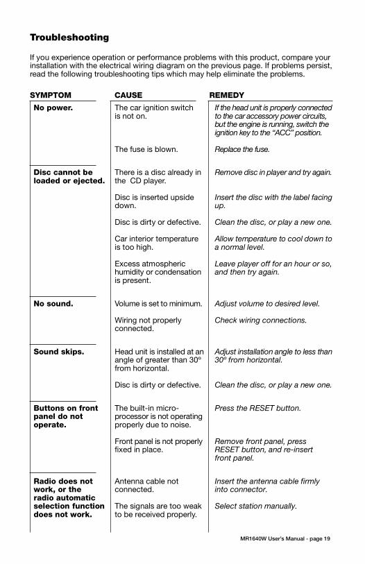
3. Push the panel mechanism back
into the housing so it is not protruding.
To do so, push the BOTTOM EDGE
down straight into the unit – do not
lift it! (Figure 7).
4. Immediately place the front panel
in its protective case for safe and
clean storage (Figure 8).
EON
EON
CONTENTS
MR1640W User’s Manual - page 1
U S E R ’ S M A N U A L
General and Tuner Controls
MR1640W User’s Manual - page 10 MR1640W User’s Manual - page 11
Wiring diagram
MR1640W User’s Manual - page 18
Troubleshooting
MR1640W User’s Manual - page 19
Specifications
MR1640W User’s Manual - page 20
MR1640W User’s Manual - page 4 MR1640W User’s Manual - page 5
Removing the head unit
Remote Control
MR1640W User’s Manual - page 14
General and Tuner Controls, continued
MR1640W User’s Manual - page 12 MR1640W User’s Manual - page 13
CD playback
MR1640W User’s Manual - page 15
MP3 disc playback
MR1640W User’s Manual - page 17
PTY Station Categories
MR1640W User’s Manual - page 6
Remote control installation
FLUSH MOUNT
MR1640W User’s Manual - page 7
Remote control installation, continued
MR1640W User’s Manual - page 16
RDS Radio functions
MR1640W User’s Manual - page 8
Remote control installation, continued
MR1640W User’s Manual - page 9
Remote control installation, continued
MR1640W User’s Manual - page 2
Head unit installation
MR2080W User’s Manual - page 3
Reinserting the front panelDetaching the front panel
MR1640 Marine MP3/CD Receiver Packing List
RESET button
Weather Band Tuning
Follow the wiring illustration below closely to obtain proper performance from your CDreceiver. Failure to make these connections properly may result in damage to your unitwhich will not be covered under your warranty.
This receiver contains a built-in high power four-channel amplifier. To use the built-inamplifier, connect the speaker wires as shown. To use the receiver as a head unit in a2CH, 4CH or 4CH-plus-subwoofer mobile audio system which includes an amplifier(s)or power subwoofer, use the RCA outputs to connect to the RCA inputs of your amplifier(s).
If you experience operation or performance problems with this product, compare yourinstallation with the electrical wiring diagram on the previous page. If problems persist,read the following troubleshooting tips which may help eliminate the problems.
No power. The car ignition switchis not on.
The fuse is blown.
If the head unit is properly connectedto the car accessory power circuits,but the engine is running, switch theignition key to the “ACC” position.
Replace the fuse.
Sound skips. Head unit is installed at anangle of greater than 30ºfrom horizontal.
Disc is dirty or defective.
Adjust installation angle to less than30º from horizontal.
Clean the disc, or play a new one.
No sound. Volume is set to minimum.
Wiring not properlyconnected.
Adjust volume to desired level.
Check wiring connections.
Should you need to remove the head
unit, first remove and store the front
panel as described on the preceding
page.
After you have removed the front panel,
insert the removal keys supplied with
the head unit into the two removal slots
as shown in the drawing until you feel
a “click.” You can now use the levers
to pull the unit from the mounting
surface. (Figures 10 and 11).
Figure 11 Insert removal keys until “click” occurs,
keys to pull out head unit.
Please follow these general instructions toplay a music CD disc. On the column tothe right, you will find instructions for usingMP3 discs.
Please note that only some of thesefunctions are available on the remote control.
Loading a discPress down the latch on the disc door asshown in the figure below, and then pushit down to open the door.
Gently insert a disc into the disc slot untilyou feel it being drawn in by the playermechanism. If there is already a disc in theplayer, first press EJECT to eject it andremove it.
Playing a discThe disc will begin playing automatically. Ifyou wish to pause playback, pressPLAY/PAUSE, and press again to resumeplayback.
To start playback from the first track, pressPRESET 1. To select the next or last tentracks to play, press the +10 or -10 button.
Intro Scan functionThe Intro Scan function is a convenient wayto find a particular track. Press this buttonand the player will play the first few secondsof a song, and then skip to the next songand play a few seconds of that song. Thisprocess continues until you press the INTRObutton again, and the player will continueplaying that song.
Repeating a trackTo keep repeating the same track, pressthe REPEAT button. To cancel the repeatfunction, press again.
Random playPressing the RANDOM will cause the playerto play all the songs on the current disc inrandom order. Press again to cancel thisfunction.
When you insert an MP3 (or WMA) disc,the player will begin playback from the firsttrack in the directory.
However, MP3 discs can contain manymore tracks than audio CD’s, so you maywish to search for a particular track to play.There are three search methods available.
TRACK SEARCH MODE
In disc playback mode, press the BANDbutton once. The LCD will display the word“TRACK.”
To begin searching, press SELECT or theUP/DOWN button. Then press and holdthe UP or DOWN button to locate thedesired track, and press SELECT to beginplayback.
NAVIGATE THE CURRENT FOLDER
This mode permits you to navigate the filedirectory present on the disc.
To enter this mode, press BAND twice. Thedisplay will display “NAVIGA.” PressSELECT to enter this mode.
Use the UP and DOWN buttons to moveup and down the directory of folders andfiles on the disc. To enter a subfolder ,highlight it and press SELECT. You will thensee the directory of that subfolder and canselect tracks within it. So play a track,highlight it and push SELECT.
VIEWING MP3 FILE INFORMATION
Since many MP3 files are tagged withMusic/Artist/Album (ID3-TAG) information,you can see this as a list by pressing AS/PSrepeatedly.
The information will appear as a scrollingdisplay, including the folder and file nameas well as the ID3-TAG information.
Please note that if this information is notpresent in ID3-TAG version 1.0 or 2.0 format,it will not be displayed.
Push down on latch torelease it, then push it down toopen the door.
FRONT AUDIO OUTPUTSBROWN CABLE
REAR AUDIO OUTPUTSGREY CABLE
RIGHT CH (RED)
LEFT CH (WHITE)
RIGHT CH (RED)
LEFT CH (WHITE)
ISO CONVERSIONCONNECTOR
OPTIONAL POWER AMPLIFIER
SPEAKER IMPEDANCE
MINIMUM 4 OHMS!
SPEAKER IMPEDANCE
MINIMUM 4 OHMS!
Place O-ring in groove on rear surface of flange of cup.
Follow these steps for a successful
installation:
1. Select the proper location which
accomodates the 3.45” overall
diameter, and mark its centerpoint.
2. Drill a hole with diameter of 3.2”-
3.3” (82-84mm). It is very important
that the hole does not exceed 3.3”.TA (Traffic Announcement)Many FM stations offer trafficannouncements in addition to their regularprogramming.
If you enable the TA function by pressingthe TA button, when this station broadcastsa traffic advisory, the radio’s RDS tuner willautomatically interrupt the regular programand play the alert. When the alert is finished,normal play of the broadcast will resume.
The TA function will also interrupt CD andMP3 playback temporarily if the EON featurehas been enabled (see below).
There are some other settings for TAbehavior that you can change. See theSELECT instructions on page 9 for moreinformation.
PTY (Program type)A number of RDS stations can be selectedby the type of program they broadcast, i.e.news, sport or classical music.
Press and hold the PTY button to cause thetuner to switch to RDS PTY type tuning. If atany time you wish to return to normal tuningmode, press and hold again.
When you have entered PTY mode, thedisplay will show “PTY” indicating that themode is enabled, and the name of the firstprogram type, “NEWS.”
To view other PTY categories, use theUP/DOWN buttons (a list of these categoriesis shown on the next page). To select thecategory, highlight it and press SELECT. Ifthere is no station found in that category, thedisplay will show “NONE PTY” and the radiowill return to normal mode.
3. Place the O-ring provided in the
groove on the rear surface of the flange
of the mounting cup.
4. Insert mounting arms fully into
mounting tube.
Mounting arms
Mounting tube
5. Insert mounting screws provided
through the slots in the cup and into
the threaded holes in the mounting
arms. Do not tighten more than a few
turns.
6. Insert this assembly fully into the
hole you have cut so that the flange
rests on the the mounting surface.
Be sure the cup is oriented with
arrow next to the word TOP is
pointing UP or your remote will be
turned when it is installed!
Insert the cup assembly fully into
the hole you have cut.
1. Place the mounting cup in the
location you wish to install it.
Using screws of suitable size and type
for your application, attach the cup to
the mounting surface. If necessary,
drill pilot holes for the screws first.
3. Press the cable into the curved
groove on the back of the remote
housing. Feed the cable end thru the
relief hole at the BACK of the cup OR
the bottom of the cup.
Be sure the cup is oriented with
arrow next to the word TOP is
pointing UP or your remote will be
turned when it is installed!
6. Grasp and turn the remote to the right
until it is in the correct position.
9. Press the cable into the curved
groove on the back of the remote
housing. Feed the cable end thru the
relief hole at the back of the cup.
10. Hold the remote in front of the cup
with the top up, and as you hold it, rotate
it about 20º counterclockwise.
11. Insert the remote control fully into the
cup so that the mounting hooks penetrate
the slots in the back of the cup.
If you feel resistance when you insert the
remote into the cup, pull the remote
housing and check that the cable has been
pressed into the curved slot, as described
in Step 2).
12. Grasp and turn the remote to the right
until it is in the correct position.
5. Insert the remote control fully into
the cup so that the mounting hooks
go through the slots in the back of the
cup.
If your installation is one in which the
cable is exiting out the bottom of the
housing (NOT the back), as you insert
the remote module pull the cable down
gently so it does not interfere with the
insertion of the remote into the cup.
4. Hold the remote in front of the cup
with the top up, and as you hold it,
rotate it about 20º counterclockwise.
2. If you are going to run the cable into
a hole in the mounting surface, drill a
hole of at least 9/16” (15mm) so that
you can pass the remote cable
connector through it.
If you are going to run the cable out
the bottom relief hole and out along
the mounting surface, skip this step.
If you feel resistance when you insert
the remote into the cup, pull the remote
housing out and check that the cable
has been pressed into the curved slot,
as described in Step 3).
To ensure that the installation
meets the IPX5 Waterproof
Standard, please follow these steps
carefully.
1. Remove the transport screws from
the top of the enclosure before
beginning the installation.
Fig 1 Remove transport screws
2. Place the two pieces of plastic film
provided over the two screw holes to
prevent water penetration.
Figure 2 Apply plastic film to seal screw holes
Figure 3 Bending the support tabs
Figure 9 Insert one end of the panel into the opening
in the main unit. Then push the other end of the
panel into main unit until you hear a “click”
1. Insert one side of the panel fully
into the opening in the main unit.
2. Then push the other end of the
front panel into the main body. You
should hear a “click.” (Figure 9)
NOTE: If the panel fails to lock into
position properly, the function of
some controls may be impaired,
and some segments of the display
may not become illuminated. If this
occurs, press RELEASE and reinstall
the front panel.
1. Press the RELEASE button to
release the panel from the right side
of the head unit (Figure 5).
2. Press the panel release latch on
the front edge of the lower surface of
faceplate, and at the same time pull
the panel forward to disengage it from
the main unit. (Figure 6).
Figure 5 Press RELEASE to release the front panel
RELEASE button
Figure 8 Place the front panel in its protective case
PUSH HERE in this direction
Figure 10 Slots for removal keys
Removal key slots
Before installing your new CD Receiver, please unpack the contents and check
that your package contains the following items:
RDS EON function settingThe RDS EON system extends thefunctionality of the TA sensing to a widerrange of traffic announcements from bothlocal and national sources. It also allows theunit to interrupt disc playback with theseannouncements. In addition, it will play theseannouncements (at normal listening level)even if the audio has been muted.
(To set this level, see instructions on page9 for setting V-PGM level).
To enable the EON function, press and holdthe SCAN button. Press again to disable it.
With EON enabled, when a trafficannouncement is broadcast, the radio willswitch automatically to TA mode, and “TP”(Traffic Program) will be displayed.
2Head unit installation
4Detaching the front panel
5Removing the head unit
6Remote control installationFlush mount
6Remote control installationSurface mount
10General and tuner controls
14Remote control
15CD Playback
15MP3 playback
16RDS radio functions
16PTY station categories
17Weather band tuning
18Wiring diagram
19Troubleshooting
20Specifications
Congratulations on your
purchase of a Marine
Weather Band MP3/CD
Receiver.
It has been designed, engineered
and manufactured to bring you
the highest level of performance
and quality, and will afford you
years of listening pleasure.
Thank you for making
Marine your choice for
marine audio entertainment!
page
RDS EuropeanFrequency Model SYMPTOM CAUSE REMEDY
Disc cannot beloaded or ejected.
There is a disc already inthe CD player.
Disc is inserted upsidedown.
Disc is dirty or defective.
Car interior temperatureis too high.
Excess atmospherichumidity or condensationis present.
Remove disc in player and try again.
Insert the disc with the label facingup.
Clean the disc, or play a new one.
Allow temperature to cool down toa normal level.
Leave player off for an hour or so,and then try again.
Buttons on frontpanel do notoperate.
The built-in micro-processor is not operatingproperly due to noise.
Front panel is not properlyfixed in place.
Press the RESET button.
Remove front panel, pressRESET button, and re-insertfront panel.
Radio does notwork, or theradio automaticselection functiondoes not work.
Antenna cable notconnected.
The signals are too weakto be received properly.
Insert the antenna cable firmlyinto connector.
Select station manually.
• Beep (when you press a button): ON/OFF
• Clock On (determines if clock will bedisplayed when radio is turned off):ON/OFF
• LCD1/2 (LCD brightness level): 1/2
RDS Radio Settings• SEEK/RDS ALLThis setting determines the behavior ofthe radio SEEK function when RDS tuningmode. If ALL is selected, the SEEKfunction will stop at both RDS and non-RDS stations. Otherwise, it will only seekRDS stations. RDS/ALL
• TA (Traffic Alert) SEEK/ALARMWhen TA mode is on, the radio monitorsthe Public Information channel which ispiggy-backed on the FM channel you arecurrently enjoying. If such a channel is notdetected or is weak the tuner will SEEKanother PI channel and monitor it.( Thisis the TA SEEK setting).
If ALARM setting is chosen, if a signal isinsufficiently strong, instead of monitoringan alternate station for PI information, theradio will produce a double beep (alarm)and silence itself, and display “LOST TPTA.” TA SEEK/ALARM
• TA VOLUMEThis setting determines the volume levelof the Traffic Alerts as they play.0-40 (18 is default)
• REG ON/OFFThis setting determines the behavior ofthe radio reception when AF (AlternateFrequency) mode is on. The AF systemcontinuously monitors the signal strengthof a station and compares it with otherstations on the same network. If anotherstation is stronger, it changes to thatstation.
Since sometimes in different regionsstations on the same network will playdifferent programs, the AF system caninterrupt the current program. If REG ONis selected, the station will check if theprograms are the same, and if not, the TAsystem will not change the station.REG OFF/ON
To turn on EON mode of RDS System,press and hold this button. When theEON function is turned on, “EON” willbe displayed on the screen (for moreinformation about the EON function seepage 16).
This list shows the PTY program types in theorder presented in the radio display:
NEWS
AFFAIRS
INFORMATION
SPORTS
EDUCATION
DRAMA
CULTURE
SCIENCE
VARIETY
POP MUSIC
ROCK MUSIC
EASY LISTENING MUSIC
LIGHT MUSIC
CLASSICAL MUSIC
OTHER MUSIC
WEATHER
FINANCE
CHILDREN
SOCIAL
RELIGIOUS
PHONE IN
TRAVEL
LEISURE
JAZZ MUSIC
COUNTRY MUSIC
NATIONAL MUSIC
OLDIES MUSIC
FOLK MUSIC
DOCUMENTARY
ALERT TEST
ALARM TEST
3. Insert and tighten the “headless”
support screw into the back of the
head unit where shown.
4. Insert the mounting case for the
head unit into the dashboard. Inspect
the dashboard material to determine
its approximate thickness. Select the
appropriate support tabs and bend
them outward to secure the bracket
in place (Figure 3).
5. Bend the backstrap to conform to
the mounting case and the dashboard
surface to which you plan to secure
the backstrap (Figure 4). Slide one of
the utility holes on the backstrap onto
the support screw and fasten it with
the spring washer and nut provided.
6. Using the 5 x 25mm screw and the
plain washer, secure the backstrap to
the dashboard surface as shown in
the diagram. Tighten, secure, and
check the overall mounting to be sure
it is safe and will not release in an
emergency stop or other sudden
movement of the vehicle.
Weather band listening is available usingTUNE/TRK buttons or the radio presets.
To hear the weather band stations, press theBAND button until the weather band isdisplayed.
The six preset buttons are assigned to thefollowing frequencies and cannot be changed:
PRESET # Frequency, MHz
1 162.40
2 162.43
3 162.45
4 162.47
5 162.50
6 162.53
if you wish to tune to the 7th available frequency,162.55MHz, use the TUNE/TRK buttons tolocate it.
Please note that in Weather Band, the followingbuttons are not operable:
SCANAS/PS
Mounting
surface
Drill a 9/16”
(15mm) or
larger hole to
allow cable to
pass through
mounting
surface.
Intallation with cable going
into hole in mounting surface.
Intallation with cable running out on top
of mounting surface.
Figure 6 Press release latch on on the lower surfaceof the front edge of the panel and pull the panel until it
is free of the head unit.
Figure 7 Push the panel mechanism back in
Slide the screws out to
extend the mounting arms
so that they reach behind
the mounting surface.
Insert the mounting screws through
the cup into the threaded holes
in the mounting arms
Hold the remote in front of
the cup, turned about
20º counterclockwise.
- OR -

3. Push the panel mechanism back
into the housing so it is not protruding.
To do so, push the BOTTOM EDGE
down straight into the unit – do not
lift it! (Figure 7).
4. Immediately place the front panel
in its protective case for safe and
clean storage (Figure 8).
EON
EON
CONTENTS
MR1640W User’s Manual - page 1
U S E R ’ S M A N U A L
General and Tuner Controls
MR1640W User’s Manual - page 10 MR1640W User’s Manual - page 11
Wiring diagram
MR1640W User’s Manual - page 18
Troubleshooting
MR1640W User’s Manual - page 19
Specifications
MR1640W User’s Manual - page 20
MR1640W User’s Manual - page 4MR1640W User’s Manual - page 5
Removing the head unit
Remote Control
MR1640W User’s Manual - page 14
General and Tuner Controls, continued
MR1640W User’s Manual - page 12 MR1640W User’s Manual - page 13
CD playback
MR1640W User’s Manual - page 15
MP3 disc playback
MR1640W User’s Manual - page 17
PTY Station Categories
MR1640W User’s Manual - page 6
Remote control installation
FLUSH MOUNT
MR1640W User’s Manual - page 7
Remote control installation, continued
MR1640W User’s Manual - page 16
RDS Radio functions
MR1640W User’s Manual - page 8
Remote control installation, continued
MR1640W User’s Manual - page 9
Remote control installation, continued
MR1640W User’s Manual - page 2
Head unit installation
MR2080W User’s Manual - page 3
Reinserting the front panelDetaching the front panel
MR1640 Marine MP3/CD Receiver Packing List
RESET button
Weather Band Tuning
Follow the wiring illustration below closely to obtain proper performance from your CDreceiver. Failure to make these connections properly may result in damage to your unitwhich will not be covered under your warranty.
This receiver contains a built-in high power four-channel amplifier. To use the built-inamplifier, connect the speaker wires as shown. To use the receiver as a head unit in a2CH, 4CH or 4CH-plus-subwoofer mobile audio system which includes an amplifier(s)or power subwoofer, use the RCA outputs to connect to the RCA inputs of your amplifier(s).
If you experience operation or performance problems with this product, compare yourinstallation with the electrical wiring diagram on the previous page. If problems persist,read the following troubleshooting tips which may help eliminate the problems.
Should you need to remove the head
unit, first remove and store the front
panel as described on the preceding
page.
After you have removed the front panel,
insert the removal keys supplied with
the head unit into the two removal slots
as shown in the drawing until you feel
a “click.” You can now use the levers
to pull the unit from the mounting
surface. (Figures 10 and 11).
Figure 11 Insert removal keys until “click” occurs,
keys to pull out head unit.
Please follow these general instructions toplay a music CD disc. On the column tothe right, you will find instructions for usingMP3 discs.
Please note that only some of thesefunctions are available on the remote control.
Loading a discPress down the latch on the disc door asshown in the figure below, and then pushit down to open the door.
Gently insert a disc into the disc slot untilyou feel it being drawn in by the playermechanism. If there is already a disc in theplayer, first press EJECT to eject it andremove it.
Playing a discThe disc will begin playing automatically. Ifyou wish to pause playback, pressPLAY/PAUSE, and press again to resumeplayback.
To start playback from the first track, pressPRESET 1. To select the next or last tentracks to play, press the +10 or -10 button.
Intro Scan functionThe Intro Scan function is a convenient wayto find a particular track. Press this buttonand the player will play the first few secondsof a song, and then skip to the next songand play a few seconds of that song. Thisprocess continues until you press the INTRObutton again, and the player will continueplaying that song.
Repeating a trackTo keep repeating the same track, pressthe REPEAT button. To cancel the repeatfunction, press again.
Random playPressing the RANDOM will cause the playerto play all the songs on the current disc inrandom order. Press again to cancel thisfunction.
When you insert an MP3 (or WMA) disc,the player will begin playback from the firsttrack in the directory.
However, MP3 discs can contain manymore tracks than audio CD’s, so you maywish to search for a particular track to play.There are three search methods available.
TRACK SEARCH MODE
In disc playback mode, press the BANDbutton once. The LCD will display the word“TRACK.”
To begin searching, press SELECT or theUP/DOWN button. Then press and holdthe UP or DOWN button to locate thedesired track, and press SELECT to beginplayback.
NAVIGATE THE CURRENT FOLDER
This mode permits you to navigate the filedirectory present on the disc.
To enter this mode, press BAND twice. Thedisplay will display “NAVIGA.” PressSELECT to enter this mode.
Use the UP and DOWN buttons to moveup and down the directory of folders andfiles on the disc. To enter a subfolder ,highlight it and press SELECT. You will thensee the directory of that subfolder and canselect tracks within it. So play a track,highlight it and push SELECT.
VIEWING MP3 FILE INFORMATION
Since many MP3 files are tagged withMusic/Artist/Album (ID3-TAG) information,you can see this as a list by pressing AS/PSrepeatedly.
The information will appear as a scrollingdisplay, including the folder and file nameas well as the ID3-TAG information.
Please note that if this information is notpresent in ID3-TAG version 1.0 or 2.0 format,it will not be displayed.
Push down on latch torelease it, then push it down toopen the door.
FRONT AUDIO OUTPUTSBROWN CABLE
REAR AUDIO OUTPUTSGREY CABLE
RIGHT CH (RED)
LEFT CH (WHITE)
RIGHT CH (RED)
LEFT CH (WHITE)
ISO CONVERSIONCONNECTOR
OPTIONAL POWER AMPLIFIER
SPEAKER IMPEDANCE
MINIMUM 4 OHMS!
SPEAKER IMPEDANCE
MINIMUM 4 OHMS!
Place O-ring in groove on rear surface of flange of cup.
Follow these steps for a successful
installation:
1. Select the proper location which
accomodates the 3.45” overall
diameter, and mark its centerpoint.
2. Drill a hole with diameter of 3.2”-
3.3” (82-84mm). It is very important
that the hole does not exceed 3.3”.TA (Traffic Announcement)Many FM stations offer trafficannouncements in addition to their regularprogramming.
If you enable the TA function by pressingthe TA button, when this station broadcastsa traffic advisory, the radio’s RDS tuner willautomatically interrupt the regular programand play the alert. When the alert is finished,normal play of the broadcast will resume.
The TA function will also interrupt CD andMP3 playback temporarily if the EON featurehas been enabled (see below).
There are some other settings for TAbehavior that you can change. See theSELECT instructions on page 9 for moreinformation.
PTY (Program type)A number of RDS stations can be selectedby the type of program they broadcast, i.e.news, sport or classical music.
Press and hold the PTY button to cause thetuner to switch to RDS PTY type tuning. If atany time you wish to return to normal tuningmode, press and hold again.
When you have entered PTY mode, thedisplay will show “PTY” indicating that themode is enabled, and the name of the firstprogram type, “NEWS.”
To view other PTY categories, use theUP/DOWN buttons (a list of these categoriesis shown on the next page). To select thecategory, highlight it and press SELECT. Ifthere is no station found in that category, thedisplay will show “NONE PTY” and the radiowill return to normal mode.
3. Place the O-ring provided in the
groove on the rear surface of the flange
of the mounting cup.
4. Insert mounting arms fully into
mounting tube.
Mounting arms
Mounting tube
5. Insert mounting screws provided
through the slots in the cup and into
the threaded holes in the mounting
arms. Do not tighten more than a few
turns.
6. Insert this assembly fully into the
hole you have cut so that the flange
rests on the the mounting surface.
Be sure the cup is oriented with
arrow next to the word TOP is
pointing UP or your remote will be
turned when it is installed!
Insert the cup assembly fully into
the hole you have cut.
1. Place the mounting cup in the
location you wish to install it.
Using screws of suitable size and type
for your application, attach the cup to
the mounting surface. If necessary,
drill pilot holes for the screws first.
3. Press the cable into the curved
groove on the back of the remote
housing. Feed the cable end thru the
relief hole at the BACK of the cup OR
the bottom of the cup.
Be sure the cup is oriented with
arrow next to the word TOP is
pointing UP or your remote will be
turned when it is installed!
6. Grasp and turn the remote to the right
until it is in the correct position.
9. Press the cable into the curved
groove on the back of the remote
housing. Feed the cable end thru the
relief hole at the back of the cup.
10. Hold the remote in front of the cup
with the top up, and as you hold it, rotate
it about 20º counterclockwise.
11. Insert the remote control fully into the
cup so that the mounting hooks penetrate
the slots in the back of the cup.
If you feel resistance when you insert the
remote into the cup, pull the remote
housing and check that the cable has been
pressed into the curved slot, as described
in Step 2).
12. Grasp and turn the remote to the right
until it is in the correct position.
5. Insert the remote control fully into
the cup so that the mounting hooks
go through the slots in the back of the
cup.
If your installation is one in which the
cable is exiting out the bottom of the
housing (NOT the back), as you insert
the remote module pull the cable down
gently so it does not interfere with the
insertion of the remote into the cup.
4. Hold the remote in front of the cup
with the top up, and as you hold it,
rotate it about 20º counterclockwise.
2. If you are going to run the cable into
a hole in the mounting surface, drill a
hole of at least 9/16” (15mm) so that
you can pass the remote cable
connector through it.
If you are going to run the cable out
the bottom relief hole and out along
the mounting surface, skip this step.
If you feel resistance when you insert
the remote into the cup, pull the remote
housing out and check that the cable
has been pressed into the curved slot,
as described in Step 3).
To ensure that the installation
meets the IPX5 Waterproof
Standard, please follow these steps
carefully.
1. Remove the transport screws from
the top of the enclosure before
beginning the installation.
Fig 1 Remove transport screws
2. Place the two pieces of plastic film
provided over the two screw holes to
prevent water penetration.
Figure 2 Apply plastic film to seal screw holes
Figure 3 Bending the support tabs
Figure 9 Insert one end of the panel into the opening
in the main unit. Then push the other end of the
panel into main unit until you hear a “click”
1. Insert one side of the panel fully
into the opening in the main unit.
2. Then push the other end of the
front panel into the main body. You
should hear a “click.” (Figure 9)
NOTE: If the panel fails to lock into
position properly, the function of
some controls may be impaired,
and some segments of the display
may not become illuminated. If this
occurs, press RELEASE and reinstall
the front panel.
1. Press the RELEASE button to
release the panel from the right side
of the head unit (Figure 5).
2. Press the panel release latch on
the front edge of the lower surface of
faceplate, and at the same time pull
the panel forward to disengage it from
the main unit. (Figure 6).
Figure 5 Press RELEASE to release the front panel
RELEASE button
Figure 8 Place the front panel in its protective case
PUSH HERE in this direction
Figure 10 Slots for removal keys
Removal key slots
Before installing your new CD Receiver, please unpack the contents and check
that your package contains the following items:
RDS EON function settingThe RDS EON system extends thefunctionality of the TA sensing to a widerrange of traffic announcements from bothlocal and national sources. It also allows theunit to interrupt disc playback with theseannouncements. In addition, it will play theseannouncements (at normal listening level)even if the audio has been muted.
(To set this level, see instructions on page9 for setting V-PGM level).
To enable the EON function, press and holdthe SCAN button. Press again to disable it.
With EON enabled, when a trafficannouncement is broadcast, the radio willswitch automatically to TA mode, and “TP”(Traffic Program) will be displayed.
2Head unit installation
4Detaching the front panel
5Removing the head unit
6Remote control installationFlush mount
6Remote control installationSurface mount
10General and tuner controls
14Remote control
15CD Playback
15MP3 playback
16RDS radio functions
16PTY station categories
17Weather band tuning
18Wiring diagram
19Troubleshooting
20Specifications
Congratulations on your
purchase of a Marine
Weather Band MP3/CD
Receiver.
It has been designed, engineered
and manufactured to bring you
the highest level of performance
and quality, and will afford you
years of listening pleasure.
Thank you for making
Marine your choice for
marine audio entertainment!
pageMR1640WFully-Marinized Weather Band MP3-Compatible In-Dash CD Receiver • RDS European Frequency Model
RDS EuropeanFrequency Model
Greater than 50dB @ 1kHz
100Hz - 20kHz
CD, CD-R, CD-RW, MP3, WMA
87.5 - 108MHz
3uV
10.7MHz
522 - 1620kHz
40dB
450kHz
162.4, 162.43, 162.45, 162.47, 162.5, 162.53, 162.55
30dB
10.7MHz
60 watts x 4 channels
12VDC, negative ground
10A Max
1200mV
7” x 2” x 6.4” (178 x 50 x 162 mm)
CD PLAYER
Signal-to-noise ratio
Frequency response
Compatible formats
RADIO
FM Section:
Frequency range
Usable sensitivity
Intermediate frequency
AM Section:
Frequency range
Usable sensitivity
Intermediate frequency
Weather Band Section:
Frequency range (MHz)
Usable sensitivity
Intermediate frequency
AMPLIFIER
Maximum output power
GENERAL
Power supply req.
Current consumption
Line out voltage
Chassis dimensions
(W X H X D)
All specifications subject to change without notice.
SYMPTOM CAUSE REMEDY
• Beep (when you press a button): ON/OFF
• Clock On (determines if clock will bedisplayed when radio is turned off):ON/OFF
• LCD1/2 (LCD brightness level): 1/2
RDS Radio Settings• SEEK/RDS ALLThis setting determines the behavior ofthe radio SEEK function when RDS tuningmode. If ALL is selected, the SEEKfunction will stop at both RDS and non-RDS stations. Otherwise, it will only seekRDS stations. RDS/ALL
• TA (Traffic Alert) SEEK/ALARMWhen TA mode is on, the radio monitorsthe Public Information channel which ispiggy-backed on the FM channel you arecurrently enjoying. If such a channel is notdetected or is weak the tuner will SEEKanother PI channel and monitor it.( Thisis the TA SEEK setting).
If ALARM setting is chosen, if a signal isinsufficiently strong, instead of monitoringan alternate station for PI information, theradio will produce a double beep (alarm)and silence itself, and display “LOST TPTA.” TA SEEK/ALARM
• TA VOLUMEThis setting determines the volume levelof the Traffic Alerts as they play.0-40 (18 is default)
• REG ON/OFFThis setting determines the behavior ofthe radio reception when AF (AlternateFrequency) mode is on. The AF systemcontinuously monitors the signal strengthof a station and compares it with otherstations on the same network. If anotherstation is stronger, it changes to thatstation.
Since sometimes in different regionsstations on the same network will playdifferent programs, the AF system caninterrupt the current program. If REG ONis selected, the station will check if theprograms are the same, and if not, the TAsystem will not change the station.REG OFF/ON
To turn on EON mode of RDS System,press and hold this button. When theEON function is turned on, “EON” willbe displayed on the screen (for moreinformation about the EON function seepage 16).
This list shows the PTY program types in theorder presented in the radio display:
NEWS
AFFAIRS
INFORMATION
SPORTS
EDUCATION
DRAMA
CULTURE
SCIENCE
VARIETY
POP MUSIC
ROCK MUSIC
EASY LISTENING MUSIC
LIGHT MUSIC
CLASSICAL MUSIC
OTHER MUSIC
WEATHER
FINANCE
CHILDREN
SOCIAL
RELIGIOUS
PHONE IN
TRAVEL
LEISURE
JAZZ MUSIC
COUNTRY MUSIC
NATIONAL MUSIC
OLDIES MUSIC
FOLK MUSIC
DOCUMENTARY
ALERT TEST
ALARM TEST
3. Insert and tighten the “headless”
support screw into the back of the
head unit where shown.
4. Insert the mounting case for the
head unit into the dashboard. Inspect
the dashboard material to determine
its approximate thickness. Select the
appropriate support tabs and bend
them outward to secure the bracket
in place (Figure 3).
5. Bend the backstrap to conform to
the mounting case and the dashboard
surface to which you plan to secure
the backstrap (Figure 4). Slide one of
the utility holes on the backstrap onto
the support screw and fasten it with
the spring washer and nut provided.
6. Using the 5 x 25mm screw and the
plain washer, secure the backstrap to
the dashboard surface as shown in
the diagram. Tighten, secure, and
check the overall mounting to be sure
it is safe and will not release in an
emergency stop or other sudden
movement of the vehicle.
Weather band listening is available usingTUNE/TRK buttons or the radio presets.
To hear the weather band stations, press theBAND button until the weather band isdisplayed.
The six preset buttons are assigned to thefollowing frequencies and cannot be changed:
PRESET # Frequency, MHz
1 162.40
2 162.43
3 162.45
4 162.47
5 162.50
6 162.53
if you wish to tune to the 7th available frequency,162.55MHz, use the TUNE/TRK buttons tolocate it.
Please note that in Weather Band, the followingbuttons are not operable:
SCANAS/PS
Mounting
surface
Drill a 9/16”
(15mm) or
larger hole to
allow cable to
pass through
mounting
surface.
Intallation with cable going
into hole in mounting surface.
Intallation with cable running out on top
of mounting surface.
Figure 6 Press release latch on on the lower surfaceof the front edge of the panel and pull the panel until it
is free of the head unit.
Figure 7 Push the panel mechanism back in
Slide the screws out to
extend the mounting arms
so that they reach behind
the mounting surface.
Insert the mounting screws through
the cup into the threaded holes
in the mounting arms
Hold the remote in front of
the cup, turned about
20º counterclockwise.
- OR -