fiery central solo for km - electronics for...
TRANSCRIPT

Fiery Central Solo for KM
Service Guide
Replacement parts and specifications aresubject to change. For a current parts list, contact your authorized service/support center.
4511306019 November 2012

© 2012 Electronics For Imaging
This documentation is protected by copyright, and all rights are reserved. No part of it may be reproduced or transmitted in any form or by any means for any purpose without express prior written consent from Electronics For Imaging (“EFI”), except as expressly permitted herein. Information in this documentation is subject to change without notice and does not represent a commitment on the part of EFI. The documentation is further covered by “Legal Notices” distributed with this product. The documentation may be provided in conjunction with EFI Software (“Software”) and any other EFI product described in the documentation. The Software is furnished under license and may only be used or copied in accordance with the terms of the EFI Software End User License Agreement, which can be found in the “Legal Notices” distributed with this product.

CONTENTS 3
CONTENTS
INTRODUCTION 9
About the FC Solo 9
About the illustrations in this document 9
Terminology and conventions 9
Precautions 11
Creating an ESD safe environment 13
Tools you will need 14
USING THE FC SOLO 15
Using the Fiery Central Bar 15
Using the FC Solo control panel 15
Buttons 16
Network Status LEDs 16
Starting, shutting down, restarting, and rebooting 17
SERVICE PROCEDURES 19
Overview 19
FC Solo overview diagrams 20
Accessing internal components 25
Shutting down the system 25
Opening the FC Solo 26
CONTENTS

CONTENTS 4
Removing and replacing FC Solo components 30
User Interface Board 31
Motherboard 33
Replacing parts on the motherboard 42
DIMM(s) 42
CPU and CPU cooling assembly 44
Chassis fan 50
Power supply 51
Hard disk drive 53
DVD drive 58
Restoring and verifying functionality after service 61
INSTALLING FC SOLO SOFTWARE 62
System software installation 62
Installing FC Solo software 63
Fiery Central License Manager 64
Installing the hardware security key 65
Configuring FC Solo 66
Fiery Central Configure 67
TROUBLESHOOTING 68
Troubleshooting process 68
Preliminary on-site checkout 69
Checking external connections 70
Checking internal components 71
Inspecting the system 72
Normal startup sequence 77
Error messages and conditions 78

CONTENTS 5
SPECIFICATIONS 86
Hardware features 86
Physical specifications 86
Safety and emissions compliance 86
INDEX 87


LIST OF FIGURES 7
LIST OF FIGURES
FIGURE 1: Fiery Central Bar 15
FIGURE 2: FC Solo control panel 15
FIGURE 3: Front and connector panels 20
FIGURE 4: Connector panel and internal side view 21
FIGURE 5: Exploded view of FC Solo components 22
FIGURE 6: Data cable connections in the FC Solo 23
FIGURE 7: Power cable connections in the FC Solo 24
FIGURE 8: Removing/replacing the side panel 27
FIGURE 9: Removing/replacing the top panel 28
FIGURE 10: Removing/replacing the front panel 29
FIGURE 11: Diagram of the User Interface Board (front and back) 31
FIGURE 12: Removing/replacing the User Interface Board 32
FIGURE 13: Motherboard battery 34
FIGURE 14: Diagram of the FC Solo motherboard 37
FIGURE 15: Removing the motherboard from the chassis 39
FIGURE 16: Standard DIMM configuration 42
FIGURE 17: Removing or replacing a DIMM 43
FIGURE 18: CPU cooling assembly 44
FIGURE 19: Removing the CPU cooling assembly 45
FIGURE 20: Removing/replacing the CPU 46
LIST OF FIGURES

LIST OF FIGURES 8
FIGURE 21: Replacing the CPU cooling assembly 47
FIGURE 22: Cooling assembly pins on the underside of the motherboard 48
FIGURE 23: Removing/replacing the chassis fan 50
FIGURE 24: Removing/replacing the power supply 52
FIGURE 25: Removing/replacing the hard disk drive bracket 55
FIGURE 26: Removing/replacing the hard disk drive from the hard disk drive bracket 56
FIGURE 27: FC Solo DVD drive 58
FIGURE 28: Removing/replacing the DVD drive bracket 59
FIGURE 29: Removing/replacing the DVD drive 60
FIGURE 30: Normal startup sequence 77

INTRODUCTION 9
INTRODUCTION
The Installation and Service Guide is intended for authorized Fiery Central Solo for KM service technicians. If you are not an authorized service technician, do not attempt to service the Fiery Central Solo for KM. Electronics For Imaging does not warrant the performance of the Fiery Central Solo for KM if it is serviced by non-authorized personnel.
NOTE: The term “FC Solo” is used throughout this document to refer to the Fiery Central Solo for KM.
About the FC SoloFC Solo is a server computer that runs Fiery Central software. Fiery Central software is a modular, PDF-based production workflow tool that provides efficient network printing to high-volume print environments.
For more information on Fiery Central software, refer to the documentation that is included in the software kit.
About the illustrations in this document
Illustrations reflect the current shipping version of the FC Solo at the time of publication. Components shown in these illustrations are subject to change. To receive information about any FC Solo components that do not match the illustrations in this document, contact your authorized service/support center.
Terminology and conventions
The following sections explain the terminology and conventions used throughout this document.

INTRODUCTION 10
FC Solo components
The terms “replace” and “replacing” are used throughout this document to refer to the reinstallation of existing components. Install new components only when necessary.
NOTE: Replacement parts and specifications are subject to change. When ordering replacement parts, refer to the current parts list maintained by your authorizedservice/support center. Install the correct parts as directed by your service/support center.
The term “control panel” refers to the area on the front of the FC Solo including the green/red activity light, the display window (LCD—liquid crystal display), and the buttons to the left and right of the display window.
The term “LCD” refers to the display window of the FC Solo control panel.
The term “monitor” refers to the FC Solo optional flat panel monitor.
The term “DVD drive” (Digital Versatile Disk drive) refers to the FC Solo DVD drive.
For other terms used to identify components of the FC Solo, see the reference key in Figure 5 on page 22.
Document conventions
NOTE: The note format highlights important messages and additional information.
The WARNING icon indicates a warning concerning operations which, if not performed correctly, may lead to death or injury. To use the FC Solo safely, always pay attention to WARNING icons and messages.
The CAUTION icon indicates a caution concerning operations which, if not performed correctly, may lead to injury. To use the FC Solo safely, always pay attention to CAUTION icons and messages.
The IMPORTANT icon indicates operational requirements and restrictions. To operate the FC Solo correctly and avoid damage to the FC Solo or other property, always pay attention to IMPORTANT icons and messages.

INTRODUCTION 11
PrecautionsAlways observe the following general precautions when installing and servicing the FC Solo:
• Never lift the print server by grasping the top panel. The top panel does not support the weight of the system.
AVERTISSEMENT: Ne jamais soulever le serveur d'impression par sa partie supérieure : celle-ci ne peut pas supporter le poids du système.
AVVERTENZA: Il server di stampa non deve essere mai sollevato afferrandolo dal pannello superiore, in quanto quest'ultimo non può sostenere il peso dell'intero sistema.
WARNUNG: Heben Sie den Druckserver nicht an der oberen Gehäuseabdeckung an. Die obere Gehäuseabdeckung ist nicht dafür ausgelegt, das Gesamtgewicht des Systems zu tragen.
ADVERTENCIA: No levante nunca el servidor de impresión agarrándolo por el panel superior. El panel superior no soporta el peso del sistema.
AVISO: Nunca erga o servidor de impressão pelo painel superior. O painel superior não suporta o peso do sistema.
WAARSCHUWING: Til de afdrukserver nooit op door het bovenpaneel vast te nemen. Het bovenpaneel kan het gewicht van het systeem niet dragen.
• Avoid pressing the surface of the LCD.
Applying excessive pressure to the LCD causes it to change color.
• Use a soft cloth moistened with Lens and Mirror Cleaner to clean the surface of the FC Solo display window.
Other solvents, such as water, may damage the polarizer on the display window.
• When connecting or disconnecting the power cord:
– Only use the power cord that shipped with the FC Solo or an appropriate replacement power cord available from an authorized provider.
– Always disconnect the power cord from the FC Solo connector panel before opening the unit and servicing internal components.
– Do not pull on the power cord when unplugging the FC Solo. Pull the plug instead.
– Do not place objects on the power cord. Place the power cord away from foot traffic.
– Do not tamper with or disable the power cord grounding plug.
– Do not use a 3-prong adapter in a 2-hole, ungrounded power outlet.
– Do not use an extension cord.
– Do not plug the FC Solo into a circuit with heating or refrigeration equipment (including water dispensers).
– Do not plug the FC Solo into a switchable power outlet. This can result in the FC Solo being turned off accidentally.
• Do not attempt to open the power supply, DVD drive, or hard disk drive.
• The FC Solo contains hazardous moving parts. When servicing the FC Solo, keep away from moving fan blades.

INTRODUCTION 12
• Handle the FC Solo LCD window with care.
If the FC Solo LCD window breaks and the liquid crystal inside leaks out, avoid contact with it. If you come in contact with the liquid crystal, wash it off your skin with soap and water immediately.
• Use care when handling parts of the FC Solo, as some edges on the unit may be sharp.
• Do not install third-party applications onto the FC Solo. Third-party applications are not supported and can cause system problems. Although virus scans are permitted on the FC Solo, virus-protection software should not be loaded in memory-resident mode.
• Do not change the Windows operating system preference settings.
Depending on the changes made, the FC Solo may become unstable or even unusable. If this occurs, it is recommended that you reinstall the FC Solo System Software, which reliably restores the Windows operating system to its factory defaults.
• Never alter an existing network without permission.
The FC Solo will probably be connected to an existing Local Area Network (LAN) based on Ethernet hardware. The network is the link between the customer’s computer, existing laser printers, and other prepress equipment. Never disturb the LAN by breaking or making a network connection, altering termination, installing or removing networking hardware or software, or shutting down networked devices without the knowledge and explicit permission of the system or network administrator or the shop supervisor.

INTRODUCTION 13
Creating an ESD safe environment• Follow standard ESD (electrostatic discharge) precautions while working on the internal
components of the FC Solo.
Static is always a concern when servicing electronic devices. It is highly unlikely that the area around the FC Solo is static-free. Carpeting, leather-soled shoes, synthetic clothing fibers, silks, and plastics may generate a static charge of more than 10,000 volts. Static discharge is capable of destroying the circuits etched in silicon microchips, or dramatically shortening their life span. By observing standard precautions, you may avoid extra service calls and save the cost of a new board.
When possible, work on a ground-connected antistatic mat. Wear an antistatic grounding strap, grounded at the same place as the antistatic mat. If that is not possible, do the following:
• Attach a grounding strap to your wrist. Attach the other end to a good ground.
• When you unpack the FC Solo from the carton for the first time, touch a metal area of the FC Solo to discharge the static on your body.
• Before you remove any of the FC Solo panels and handle internal components, touch a metal part of the FC Solo.
• Leave new electronic components inside their antistatic bags until you are ready to install them. When you remove components from an antistatic bag, place them on a grounded antistatic surface, component-side up.
• When you remove an electronic component, place it in an antistatic bag immediately. Do not walk across a carpet or vinyl floor while carrying an unprotected board.
• During service to the motherboard, avoid using excessive force and always place the motherboard on a grounded, nonmetallic, static-free surface. Never allow any metal to touch the solder contacts on the underside of the motherboard, especially beneath the battery socket. Improper handling can short-circuit and permanently damage the motherboard.
• Handle printed circuit boards by their opposing edges only and avoid touching the contacts on the edge of the board.

INTRODUCTION 14
Tools you will needTo service the FC Solo, the following tools and parts are required:
• ESD wrist grounding strap and antistatic mat
• Flathead screwdriver
• #0, #1, and #2 Phillips-head screwdrivers
• FC Solo documentation, including the customer media pack and any related service bulletins
Avoid touching magnetic tools to storage media such as hard disk drives. Contact between magnetic tools and magnetic storage media may result in data corruption.
NOTE: The FC Solo Service Guide is not intended for customer use. Do not leave the Service Guide at the customer site after servicing the FC Solo.

USING THE FC SOLO 15
USING THE FC SOLO
This chapter includes the following information:
• Using the Fiery Central Bar
• Using the FC Solo control panel
• Checking Network status LEDs
• Shutting down and restarting the FC Solo
Using the Fiery Central BarThe Fiery Central Bar on the monitor provides access to all administrative server functions. The Fiery Central Bar appears at the top of the screen when FC Solo is running, and shows the status of jobs currently processing and printing on the Fiery Central Server.
Right-clicking the Fiery Central Bar displays a menu that contains some of the same operational functions available in Command WorkStation.
FIGURE 1: Fiery Central Bar
Using the FC Solo control panelDuring normal FC Solo operation, the control panel displays a static logo screen and the buttons are not functional. However, during installation of FC Solo server software, the control panel displays screens that allow you to proceed through the steps of the installation.
FIGURE 2: FC Solo control panel
Display window
Line selectionbuttons
Up button
First
Fourth
Menu button
Down button
Activity light

USING THE FC SOLO 16
Buttons
Network Status LEDs
Two LEDs next to the Ethernet network port indicate the network speed. When data transfer occurs between the FC Solo and the network, the appropriate LED(s) blink to indicate network activity.
Line selection buttons
Use the four line selection buttons on the right side of the control panel to select the command displayed on the corresponding line of the LCD display.
Up and Down buttons
Use these buttons to scroll to different screens in multi-screen lists or prompts.
Menu button This button is not functional.
Network link speed LED 1 LED 2
10 Megabits/second Off Green
100 Megabits/second Green Green
1000 Megabits/second Amber Green
LED 2
LED 1
Ethernet network port(Upper RJ-45)

USING THE FC SOLO 17
Starting, shutting down, restarting, and rebooting The customer will generally leave the FC Solo on all the time. Power off the FC Solo when you need to service it and before you remove or attach any cables to it.
TO START THE FC SOLO
1 Make sure that the power cable is attached and that the power switch is in the ON position.
2 Press the power button on the front panel.
3 Check the Activity light on the control panel.
The power supply automatically senses the correct voltage. Allow startup to proceed without interruption.
4. At the Admin login, enter the password, and then press Enter. Wait for Command WorkStation to start and for Fiery Central Bar to indicate that the FC Solo is Idle.
Fiery.1. is the default password and is case-sensitive. However, the network administrator may have changed the password.
During installation, a localhost connection to Command WorkStation is created, so when you start the FC Solo, Command WorkStation starts also.

USING THE FC SOLO 18
TO SHUT DOWN OR REBOOT THE FC SOLO
NOTE: A monitor, keyboard, and mouse are required to shut down or reboot the FC Solo. Use the reset button on the front of the FC Solo only if the system is unresponsive to keyboard or mouse actions.
1 On the monitor, click the Windows Start button.
2 Do one of the following:
• To shut down the FC Solo, click “Shut down.”
• To reboot the FC Solo operating system, click the triangle next to “Shut down” and then click Restart.
TO RESTART THE FC SOLO SERVER
• On the monitor, right-click Fiery Central Bar and click Restart Fiery Central.
SERVICE PROCEDURES 19
SERVICE PROCEDURES
Generally, the FC Solo requires no regular service or maintenance. Use the procedures in this chapter to inspect, remove, reseat, and replace major hardware components if needed.
OverviewThis chapter includes information about servicing the following components:
• Boards and cables
• Motherboard components (DIMMs, CPU, battery, CMOS, and jumpers)
• Fan
• Power supply
• Hard disk drive
Replacement parts are available from your authorized service representative. The terms “replace” and “replacing” are used throughout this document to mean the reinstallation of existing components. Install new components only when necessary. If you determine that a component you have removed is not faulty, make sure to reinstall it.
Replacement parts and specifications are subject to change. When ordering replacement parts, refer to the current parts list maintained by your authorized service/support center. Install the correct parts as directed by your service/support center.
When performing the service procedures described in this chapter, follow the precautions listed on page 11.
The tools required to service the FC Solo are listed on page 14.

SERVICE PROCEDURES 20
FC Solo overview diagrams
The following figures provide an overview of FC Solo components.
FIGURE 3: Front and connector panels
Front panel
USB ports
Monitor (option)
Power switch
Connector panel
Network port
USB port
DVD drive
control panel
Power button
Reset button
Power connector

SERVICE PROCEDURES 21
FIGURE 4: Connector panel and internal side view
Key
1 USB ports (x4)2 Monitor (option)3 Network port4 Power connector5 Power switch6 Power supply
7 DIMM slots 8 CPU cooling assembly9 Chassis fan
10 DVD drive11 Hard disk drive12 Motherboard
NOT SHOWN: Cables, UIB, or front panel USB port.
1
2
3
4
10
11
5
21
6
7
8
9

SERVICE PROCEDURES 22
FIGURE 5: Exploded view of FC Solo components
18
5
1
8
11
16
12
20
19
3
2
4
10
7
17
21
13
14
Key
1 Front panel2 Hard disk drive bracket3 Hard disk drive4 Side panel5 DIMMs
6 CPU cooling assembly7 CPU8 Battery9 Motherboard
10 Power supply
11 Chassis fan12 Chassis13 Top panel14 UIB15 UIB buttons
16 Hard disk drive SATA cable17 DVD drive bracket18 DVD drive19 DVD drive power/data combo cable20 UIB cable21 Front panel USB port and cable
NOT SHOWN: Tie-wraps, cable clamps, dongle(s), or external cables.
15
6
9

SERVICE PROCEDURES 23
FIGURE 6: Data cable connections in the FC Solo
Cable key From To
1 UIB cable User Interface Board Motherboard USB connector
2 Hard disk drive data cable Hard disk drive Motherboard connector SATA 2
3 DVD drive power/data combo cable DVD drive Motherboard connector SATA 1 and power supply
4 Front panel USB port cable Front panel USB port Motherboard USB connector
Motherboard data connection detail
4
3
2
4
1
1
1
3
2
4

SERVICE PROCEDURES 24
FIGURE 7: Power cable connections in the FC Solo
Cable key From To
1 Power supply cable Power supply a. CPU power connector, 4-pin (PW2)
b. Motherboard power connector, 20-pin (PW1)
c. DVD drive power/data combo cable
d. Hard disk drive power connector
e. Power switch, connector panel (Attach the black and white leads to either terminal on the power switch.)
2 Reset cable Reset button, front panel Motherboard connector J14, pins 5 and 7; align triangle on cable connector as shown
3 Power cable Power button, front panel Motherboard connector J14, pins 6 and 8; align triangle on cable connector as shown
4 CPU fan cable CPU fan Motherboard connector FAN 1
5 Chassis fan cable Chassis fan Motherboard connector FAN 2
J14
1a
1c
1b
1d
45
23
Reset button
Power button
Reset & Power buttonconnection detail
1e
2
3

SERVICE PROCEDURES 25
Accessing internal componentsThis section describes how to shut down and open the FC Solo. Always use the following procedures when opening the FC Solo for inspection or service.
Shutting down the system
If the FC Solo is powered on, you must shut down the system and remove the power cable from the connector panel before removing or connecting interface cables or accessing the internal components.
NOTE: Always obtain permission from the network administrator before you take the FC Solo off the network.
If you are cycling power, wait at least 10 seconds before powering back on.
If you are unable to shut down the FC Solo from the monitor, power off by holding down the power button on the front of the FC Solo for up to eight seconds.
Using the reset button may cause the system to operate unpredictably; therefore, use the reset button on the front of the FC Solo only if the system is frozen and unresponsive to keyboard or mouse actions.
TO SHUT DOWN THE FC SOLO
Always verify that the FC Solo is not in use before you begin the following procedure.
1 Ensure that the FC Solo is not receiving, processing, or printing any files.
If the system has just finished processing, wait at least 10 seconds after the system reaches Idle before beginning the shutdown procedure.
NOTE: Notify the network administrator before you remove the FC Solo from the network.
2 On the monitor, click the Windows Start button and then click Shut down.
Before accessing internal components, make sure that all cables are disconnected from the back of the FC Solo.

SERVICE PROCEDURES 26
Opening the FC Solo
To service internal components, you must open the FC Solo when you need to repair or replace any components.
TO OPEN THE FC SOLO
1 Shut down the FC Solo (see page 25).
2 Remove all external cables from the FC Solo.
3 Remove all panels necessary to access the component that you want to service.
For guidelines on which panels to remove, see the service procedure for the component that you want to service.
NOTE: When removing multiple panels from the FC Solo, use the following order:
• Side panel (see page 27)
• Top panel (see page 28)
• Front panel (see page 29)
NOTE: When replacing panels, reverse the order.
4 Place the FC Solo on a flat surface. Attach an ESD wrist strap before handling internal parts (see “Precautions” on page 11).
5 Carefully position the FC Solo so that it is resting on its side and the internal components are facing up.
Place removed components on a grounded, antistatic surface.

SERVICE PROCEDURES 27
TO REMOVE AND REPLACE THE SIDE PANEL
1 Shut down the FC Solo (see page 25).
2 Remove the two screws that attache the side panel to the back of the chassis.
Set aside the screws so that you can replace them later.
3 Slide the side panel toward the connector panel.
It may help to use the palm of your hand to press down on the side panel as you slide it.
4 Lift the side panel off the chassis.
FIGURE 8: Removing/replacing the side panel
NOTE: Before you replace the side panel, make sure the top and front panels are installed.
5 To replace the side panel, fit the front edge of the panel under the front panel, and then slide the side panel in place. Replace the screws that you removed earlier.
Make sure not to damage cables as you replace the panel. Fold all cables inside the chassis before closing the panel against the chassis.
Side panel

SERVICE PROCEDURES 28
TO REMOVE AND REPLACE THE TOP PANEL
NOTE: To remove the top panel, you must first remove the side panel.
1 Shut down the FC Solo (see page 25).
2 From inside the chassis, bend the four tabs that secure the top panel to the chassis until they disengage the slots in the chassis, and then lift the top panel away from the chassis.
It may help to partially loosen the tabs one at a time as you disengage them from the chassis.
FIGURE 9: Removing/replacing the top panel
3 To replace the top panel, align the tabs on the underside of the panel with the slots on the top of the chassis.
4 Press the top panel against the chassis and snap it into place.
Snap the tabs into place one at a time until all four tabs have engaged the chassis.
Top panel
Tab and slot (1 of 4)

SERVICE PROCEDURES 29
TO REMOVE AND REPLACE THE FRONT PANEL
NOTE: To remove the front panel, you must first remove the side and top panels.
1 Shut down the FC Solo (see page 25).
2 From inside the chassis, bend outward on the four tabs that secure the front panel to the chassis, and then lift the panel away from the chassis.
It may help to partially loosen the tabs one at a time as you disengage them from the chassis.
FIGURE 10: Removing/replacing the front panel
3 To replace the front panel, align the openings in the panel with the DVD drive, power and reset buttons, and USB port.
4 Press the panel against the chassis and snap it into place.
Snap the tabs into place one at a time until all four tabs have engaged the chassis.
Tab (1 of 4)
Front panel

SERVICE PROCEDURES 30
Removing and replacing FC Solo componentsBefore replacing costly components, be sure to verify the connections between the copier and the FC Solo. Also, verify the connections of each replaceable FC Solo component. For more information about troubleshooting, see “Troubleshooting” on page 68.
The following sections describe how to remove and install replaceable parts on the FC Solo:
• User Interface board
• Motherboard
• Battery
• DIMM(s)
• CPU and CPU cooling assembly
• Chassis fan
• Power supply
• Hard disk drive
• DVD drive
Be sure to use an ESD grounding wrist strap and follow standard ESD (electrostatic discharge) precautions while performing these procedures. For details, see “Precautions” on page 11.

SERVICE PROCEDURES 31
User Interface Board
The User Interface Board (UIB) provides the interface between the FC Solo and the user. The front of the UIB contains circuitry for the following:
• Activity lights (amber, green, and red LEDs)
• Display window (LCD)
• Four line selection buttons
• Up and Down buttons
• Menu button
• Jewel lights
The UIB cable is routed from a connector on the User Interface Board to a USB connector on the motherboard (see Figure 14 on page 37).
FIGURE 11: Diagram of the User Interface Board (front and back)
Back
Front
Line selection button pads
UIB cable connector
Activity lights (LEDs)
Display window
Up button pad
Menu button pad
Down button pad

SERVICE PROCEDURES 32
TO REMOVE THE USER INTERFACE BOARD
1 Shut down and open the FC Solo (see pages 25 and 26).
To access the User Interface Board, you must remove the side, top, and front panels.
2 Detach the UIB cable from the connector on the top of the UIB.
Detach the UIB cable by grasping the cable connector. Avoid pulling on the cable.
3 Remove the four screws that secure the UIB to the mount on the top panel.
4 Lift the UIB off the mount.
FIGURE 12: Removing/replacing the User Interface Board
5 Place the UIB in an antistatic bag.
6 Attach the UIB cable to the connector on the top of the UIB (see Figure 12 on page 32).
7 Secure the UIB to the mount on the top panel.
Replace the four screws that secure the UIB to the mount on the top panel. Be sure to use the same screws that you removed earlier.
8 If you are replacing the UIB cable with a new cable, attach the new UIB cable to the connector on the top of the UIB, and then route the cable through the hole in the top of chassis and connect it to a USB port on the motherboard.
9 Replace the top panel (see page 28).
10 Reassemble the FC Solo and verify its functionality (see page 61).
UIB cable connector
Screw (1 of 4)
UIB cable

SERVICE PROCEDURES 33
Motherboard
This section describes the battery and default jumper settings on the FC Solo motherboard, as well as procedures for removing and replacing the motherboard.
NOTE: Do not move or change any of the default jumper configurations on the motherboard.
Battery
The battery is located on the motherboard. Spare batteries are not provided by your authorized service/support center. If you must replace the battery, use a 3V manganese dioxide lithium coin cell battery (Panasonic CR2032 or equivalent).
There is a danger of explosion if the battery is replaced with the incorrect type. Replace it only with the same type recommended by the manufacturer. Dispose of used batteries according to the manufacturer’s instructions.
ACHTUNG: Es besteht Explosionsgefahr, wenn die Batterie durch eine Batterie falschen Typs ersetzt wird. Als Ersatz dürfen nur vom Hersteller empfohlene Batterien gleichen oder ähnlichen Typs verwendet werden. Verbrauchte Batterien müssen entsprechend den Anweisungen des Herstellers entsorgt werden.
ATTENTION: Il y a risque d’explosion si la pile est remplacée par un modèle qui ne convient pas. Remplacez-la uniquement par le modèle recommandé par le constructeur. Débarrassez-vous des piles usées conformément aux instructions du constructeur.
ADVARSEL!: Lithiumbatteri - Eksplosionsfare ved fejlagtig håndtering Udskiftning må kun ske med bat-teri af samme fabrikat og type. Levér det brugte batteri tilbage til leverandøren.
VAROITUS: Paristo voi räjähtää, los se on virheellisesti asennettu. Vaihda paristo ainoastaan laitevalmistajan suosittelemaan tyyppiin. Hävitä Käytetty paristo valmistajan ohjeiden mukaisesti.
ADVARSEL: Eksplosjonsfare ved feilaktig skifte av batteri. Benytt samme batteritype eller en tilsvarende type anbefalt av apparatfabrikanten. Brukte batterier kasseres i henhold til fabrikantens instruksjoner.
VARNING: Explosionsfara vid felaktigt batteribyte. Använd samma batterityp eller en ekvivalent typ som rekommenderas av apparat-tillverkaren. Kassera använt batteri enligt fabrikantens instruktion.

SERVICE PROCEDURES 34
TO REPLACE THE BATTERY
1 Access and open the FC Solo as described on page 26.
2 Locate the battery on the motherboard (see Figure 14 on page 37).
3 Carefully push the clip away from the battery until the socket ejects the battery.
FIGURE 13: Motherboard battery
4 Slide the battery out of its socket.
5 To insert a new battery, slide it into the socket so that the positive (+) side of the battery faces up.
6 Press the battery down into the socket until it snaps into place.
Make sure that the battery is securely installed in the socket.
7 Reassemble the FC Solo and verify functionality (see page 61).
8 Configure the system date and time (see page 35).
Battery
Socket
Clip

SERVICE PROCEDURES 35
TO CONFIGURE THE SYSTEM DATE AND TIME
1 On a client computer that is connected to the same network as the FC Solo, open a Web browser window.
2 In the URL field of the browser, type the IP address or DNS name of the FC Solo, and press Enter.
The IP address is listed under the Network Setup section of the FC Solo Configuration page.
3 On the WebTools home page, click the Configure tab.
4 Click Launch Configure, type the Administrator password for the FC Solo, and then click OK.
The default Administrator password is Fiery.1. However, the network administrator may have configured a new password for the FC Solo.
5 Expand the Server item in the left pane, and click General.
6 Click the Set button next to Date and Time.
7 In the dialog box that appears, specify the current date and time, and click OK.
8 In the Setup window, click Apply.
9 Click Reboot.

SERVICE PROCEDURES 36
Motherboard jumpers
The following table describes the jumper pin locations on the motherboard. Do not move or change any of the default jumper configurations.
TABLE 1: Jumper pins on the motherboard
Location on motherboard Default jumper configuration
JP7 (on edge of motherboard, near PCI connectors)
No jumper installed
J17 (on corner of motherboard, near SATA connectors)
Jumper is installed on pins 1 and 2(pin 1 is indicated by a silkscreened triangle)
J18 (on edge of motherboard, near the on-board speaker)
Jumper is installed on pins 1 and 2(pin 1 is indicated by a silkscreened triangle)

SERVICE PROCEDURES 37
FIGURE 14: Diagram of the FC Solo motherboard
1
5
4MH
9
MH 23
22
MH
2 3MH
10
12
21
24
25
MH13
1314
15
6
7
8
11
1720
1819
16
26
Key
1 8-pin power connector (pins 1–4 used)2 Chassis connector (FAN1)3 CPU fan connector (CPUFAN)4 FAN2 connector (not used)5 24-pin power connector (pins 1–20 used)6 2GB DIMM (DIMM2)7 2GB DIMM (DIMM1)8 CPU and cooling assembly9 USB ports
10 Serial port (not used)
11 Monitor port12 Network port (10/100/1000BaseT)13 Battery (BT1)14 FAN3 connector (not used) 15 Empty PCIE slot (PCIE1) 16 Empty PCIE slot (PCIE2)17 Front panel USB connectors18 Reset and Power button (J14)19 SATA 6 connector (not used)
20 SATA 5 connector (not used)21 SATA 4 connector (not used)22 SATA 3 connector (not used)23 Hard disk drive connector (SATA 2)24 DVD data connector (SATA 1)25 Speaker26 Jumper (J17)MS (Mounting screws)
NOTE: Any connectors not listed are not used.

SERVICE PROCEDURES 38
Removing the motherboard
Before you remove the motherboard, you must remove:
• All cables connected from other components to the motherboard
• The power supply
Follow standard ESD precautions while handling the motherboard and all components. For details, see “Precautions” on page 11.
TO REMOVE MOTHERBOARD COMPONENTS FROM THE MOTHERBOARD
1 Access and open the FC Solo, as described on page 26.
2 Remove the following cables attached to the motherboard:
• Reset button cable
• Power button cable
• UIB cable (USB)
• Front panel USB port cable (USB)
• DVD drive power/data combination cable
• Hard disk drive data cable
• Motherboard power cable (20-pin)
• CPU power cable (4-pin)
• Chassis fan power cable
For the location of each connector on the motherboard, see Figure 14 on page 37.

SERVICE PROCEDURES 39
TO REMOVE THE MOTHERBOARD
Follow ESD and other safety precautions when handling the motherboard. Do not touch the contacts and avoid using excessive force. Place the motherboard on a grounded, anti-static surface.
1 Remove the power supply (see page 52).
2 Remove the five mounting screws that secure the motherboard to the base of the chassis (see Figure 14 on page 37 for the screw locations on your motherboard).
To minimize tension on the motherboard, loosen all the screws partially before removing any one screw completely.
3 Lift the edge of the motherboard opposite the connector panel to release the motherboard from the chassis. Then gently slide the motherboard out of the chassis.
Make sure that the connectors on the motherboard clear the cutouts in the chassis as you remove the board. Avoid handling contacts or using excessive force.
FIGURE 15: Removing the motherboard from the chassis
4 If you are replacing the motherboard with a new motherboard, remove the following from the old motherboard:
• DIMM(s) (see page 42)
• CPU (see page 44)
Lift edge of motherboard and remove from chassis.
Make sure that the motherboard connectors clear the cutouts in the chassis (cutouts not shown).

SERVICE PROCEDURES 40
Replacing the motherboard
Use the following procedure to install the motherboard in the FC Solo chassis.
TO REPLACE THE MOTHERBOARD
1 If you are installing a new motherboard, do the following:
• Install the DIMM(s) from the old motherboard onto the new motherboard (see page 42).
• Install the CPU from the old motherboard onto the new motherboard (see page 44).
When installing these components, make sure that the motherboard is placed on an antistatic surface with some padding.
Do not transfer the BIOS chip from the old motherboard onto the new motherboard. Doing so can cause the system to shut down due to incompatibility issues.
2 Angle the motherboard so that the connectors on the motherboard fit into the cutoutsin the connector panel of the chassis, and gently slide the motherboard into the chassis (see Figure 15 on page 39).
Be sure to fit the motherboard Ethernet connectors under the metal grounding tabs in the cutouts. Failure to position the grounding tabs correctly may result in permanent damage to the motherboard and power supply.
3 Align the mounting holes on the motherboard with the screw holes located in the base of the chassis (see Figure 14 on page 37 for the mounting hole locations).
4 Insert the five mounting screws that attach the motherboard to the chassis.
Partially tighten each screw before completely tightening any one screw. Do not overtighten the screws; doing so could damage traces on the motherboard.
5 Replace the power supply (see page 51).
Now you are ready to replace the remaining motherboard components to complete the motherboard installation.

SERVICE PROCEDURES 41
TO REPLACE MOTHERBOARD COMPONENTS
1 Replace the following cables to the motherboard (for the location of each connector on the motherboard, see Figure 6 on page 23 and Figure 7 on page 24):
• Reset button cable
• Power button cable
• 20-pin power cable: Install the cable in pins 1–20 of the 24-pin connector on the motherboard. The cable connector is keyed to fit only one way.
• 4-pin power cable: Install the cable in pins 1–4 of the 8-pin connector on the motherboard. The cable connector is keyed to fit only one way.
• Hard disk drive data cable
• DVD drive data cable
• Chassis fan cable
• UIB cable (USB)
• Front panel USB port cable (USB)
2 Reassemble the FC Solo (see page 61).

SERVICE PROCEDURES 42
Replacing parts on the motherboard
This section describes how to remove and replace the DIMM(s), CPU, and battery on the motherboard. Before you perform any of these procedures, shut down and open the FC Solo (see page 25).
DIMM(s)
Each DIMM (dual in-line memory module) is held in place by levers at each end of the DIMM socket. The motherboard provides two DIMM sockets (DIMM1 and DIMM2).
The standard memory configuration populates both DIMM sockets with a 2GB DIMM for a total of 4GB of memory.
NOTE: A DIMM must be installed in DIMM2 in order for the FC Solo to start up. If no DIMM is installed in DIMM2, the system will sound six long beeps.
When installing DIMMs of different capacities, be sure to install the lower-capacity DIMM in socket DIMM2. Approved DIMMs are available from your authorized service/support center.
FIGURE 16: Standard DIMM configuration
DIMM2
DIMM1

SERVICE PROCEDURES 43
TO REMOVE OR REPLACE A DIMM
1 Shut down and open the FC Solo (see pages 25 and 26).
To remove a DIMM, you must remove the side panel.
2 To release a DIMM, push outward on the levers on each side of the DIMM.
FIGURE 17: Removing or replacing a DIMM
3 Lift the DIMM straight out of the socket.
4 To replace a DIMM, position the DIMM in the socket and press the DIMM straight down into the socket so the levers lock the DIMM into place.
NOTE: DIMMs fit in the socket only one way. The notch on the bottom of each DIMM should line up with the notch in the socket.
Make sure that the levers close securely around the ends of the DIMM and each DIMM is fully seated in its socket.
NOTE: For a single-DIMM configuration, you must install the DIMM in socket DIMM2. Installing the single DIMM in socket DIMM1 is incorrect and can cause problems with system performance.
5 If you installed a new DIMM(s), clear the CMOS.
You must clear the CMOS after installing a new DIMM(s) to ensure compatibility between the new component and the previous settings stored in the BIOS.
NOTE: Make sure that the power cable is removed from the power outlet before clearing CMOS.
• Remove the battery (see page 50).
• Wait 2 minutes to allow the motherboard electrical components to fully discharge.
• Reinstall the battery (see page 50).
6 Reassemble the FC Solo and verify functionality (see page 61).
7 If you installed a new DIMM and cleared CMOS, make sure to reset the system date and time (see page 35).
DIMM
Lever
LeverSocket notch
SERVICE PROCEDURES 44
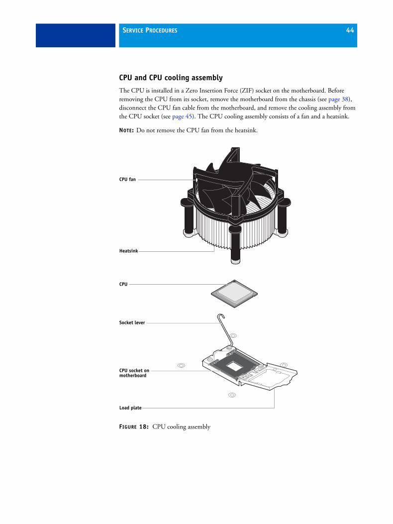
CPU and CPU cooling assembly
The CPU is installed in a Zero Insertion Force (ZIF) socket on the motherboard. Before removing the CPU from its socket, remove the motherboard from the chassis (see page 38), disconnect the CPU fan cable from the motherboard, and remove the cooling assembly from the CPU socket (see page 45). The CPU cooling assembly consists of a fan and a heatsink.
NOTE: Do not remove the CPU fan from the heatsink.
FIGURE 18: CPU cooling assembly
CPU fan
Heatsink
Load plate
CPU socket on motherboard
CPU
Socket lever

SERVICE PROCEDURES 45
TO REMOVE A CPU
1 Access and open the FC Solo, as described on page 27.
2 Remove the motherboard components (see page 39).
3 Remove the power supply (see page 52).
4 Remove the motherboard from the chassis (see page 39).
Place the motherboard on a flat, anti-static surface.
5 Remove the CPU fan cable from its motherboard connector.
6 Remove the CPU cooling assembly:
Be aware that both the cooling assembly and the CPU may be very hot. You may need to allow the components to cool before you attempt to remove them.
• Rotate each fastener one quarter-turn counterclockwise to the position shown below.
• Pull straight up on each fastener cap until the retaining tang at the tip of the peg is released from the motherboard.
You may need to use moderate force to pull the pegs and pins out of the motherboard. Be careful not to damage nearby components on the motherboard or the CPU cooling assembly when pulling up on the fasteners.
FIGURE 19: Removing the CPU cooling assembly
7 Lift the cooling assembly off the CPU socket and set it aside.
Use caution when lifting the cooling assembly off the CPU, because the thermal compound at the base of the heatsink may damage the CPU if the heatsink is removed too forcefully.
Rotate each fastenerto this position.
Peg

SERVICE PROCEDURES 46
8 Unlock the CPU socket lever and raise it into the open position (flex the lever away from the retention post, and then raise it).
9 Open the load plate (see Figure 20).
FIGURE 20: Removing/replacing the CPU
10 Grasp the CPU by its edges, lift it out of the socket, and then place the CPU in a safe place.
NOTE: If you remove the CPU from the motherboard to install it on a new motherboard, unpack the new motherboard and remove the protective plastic cover from the CPU socket. Transfer the protective cover to the CPU socket of the old motherboard to protect the circuitry.
TO REPLACE A CPU
1 Do one of the following:
• If you are installing a new CPU cooling assembly on an existing CPU, clean the contact surface of the CPU to remove any old thermal compound residue. A thermal pad is preinstalled on the underside of the new CPU cooling assembly.
Be sure to remove all thermal compound residue from the surface of the CPU. It may help to scrape all the residue off the surface using the flat edge of a non-conductive tool. Then use a lint-free cloth moistened with alcohol to clean the surface.
• If you are installing the existing CPU and CPU cooling assembly on a new motherboard, clean the contact surfaces of the CPU and cooling assembly as described above. Then apply fresh thermal compound to the contact surface of the CPU using the applicator provided with the new motherboard.
2 Prepare the CPU socket by ensuring that:
• The socket lever is in the open position.
• The load plate is open.

SERVICE PROCEDURES 47
3 Place the CPU in the socket (see Figure 20 on page 46).
The CPU and the socket are keyed to ensure correct installation. The notches on the edges of the CPU correspond with the two small posts inside the socket. Align the yellow triangle on the CPU with the yellow arrow stenciled on the motherboard next to the socket. Do not force the CPU.
4 Close the load plate.
5 Lower the socket lever and place it in the locked position under the retention post.
6 Prepare the CPU cooling assembly for installation.
• Make sure that the motherboard is placed on a padded, static-free work surface.
• If you are transferring the CPU and CPU cooling assembly from an old motherboard to a new motherboard, apply fresh thermal compound to the surface of the CPU, as described in step 1 on page -46.
• Rotate fasteners to the position shown below by turning them clockwise (that is, in the opposite direction of the arrow on top of the fastener).
• Ensure that the pin inside each peg is fully retracted upward.
FIGURE 21: Replacing the CPU cooling assembly
7 Place the heatsink over the CPU socket.
• Align the cooling assembly so that when it is installed, the fan cable easily reaches connector CPUFAN on the motherboard.
• Align the pegs over their mounting holes in the motherboard.
NOTE: Make sure that each fastener is rotated to the position shown in Figure 21.
Before placing the cooling assembly on the socket, rotate each fastener tothis position.
PegEnsure that each pin is fully retracted upward inside its peg.

SERVICE PROCEDURES 48
8 At opposite corners, press down on each fastener until the retaining tang at the tip of the peg clicks into locked position and the fastener cannot be pressed down further. Engage all four pegs.
NOTE: Do not rotate the fasteners after installation.
Engaging the pegs at opposite corners applies clamping force equally over the CPU and socket. Avoid using excessive force and take care not to flex the motherboard when you engage the pegs.
9 Turn the motherboard over and verify the following:
• Each black pin protrudes through the mounting hole on the underside of the motherboard.
• Each black pin is flush with the tip of the peg.
FIGURE 22: Cooling assembly pins on the underside of the motherboard
10 Connect the CPU fan cable to the motherboard connector CPUFAN.
The cable connector is keyed to fit only one way. Make sure that the connector on the cable is securely attached to connector CPUFAN on the motherboard.
11 Install the motherboard in the chassis (see page 40).
12 Replace the power supply (see page 53).
Straight-on view
Cross-sectional view
SERVICE PROCEDURES 49
13 Replace the motherboard components (see page 42).
14 If you installed a new CPU, clear the CMOS.
You should clear the CMOS after installing a new CPU to ensure compatibility between the new component and previous settings stored in the BIOS.
NOTE: Be sure to remove the power cable from the FC Solo before clearing the CMOS.
• Remove the battery (see page 33).
• Wait two minutes to allow the motherboard electrical components to fully discharge.
• Reinstall the battery (see page 33).
15 Reassemble the FC Solo and verify its functionality (see page 61).
If you installed a new CPU and cleared the CMOS, configure the system time and date (see page 35).

SERVICE PROCEDURES 50
Chassis fan
A fan mounted inside the chassis blows air out of the FC Solo to cool components. The chassis fan runs continuously when the system is on. You should hear the chassis fan start as soon as you power on the FC Solo. If you do not hear the chassis fan, there may be a faulty power connection (see Figure 7 on page 24).
The following procedures describe how to remove and replace the chassis fan.
TO REMOVE AND REPLACE THE CHASSIS FAN
1 Shut down and open the FC Solo (see pages 25 and 26).
To access the chassis fan, you must remove the side panel.
2 Remove the fan cable from its motherboard connector.
3 Remove the four screws that attach the chassis fan to the chassis, and then remove the fan.
Set the screws aside so that you can replace them later.
FIGURE 23: Removing/replacing the chassis fan
4 To replace the chassis fan, reverse the removal steps.
An arrow on the side of the chassis fan indicates the airflow direction. Make sure that the chassis fan is positioned with the label against the chassis.The chassis fan should blow air out of the vents in the connector panel when the system is reassembled and powered on (see Figure 23).
5 Verify FC Solo functionality (see page 61).
Screw (1 of 4)
Chassis fan
Airflow direction
SERVICE PROCEDURES 51
Power supply
This section describes how to remove and replace the FC Solo power supply. For more information on the power supply, see “Specifications” on page 86.
NOTE: Do not open the power supply for service or troubleshooting. Opening the power supply will void the warranty.

SERVICE PROCEDURES 52
TO REMOVE THE POWER SUPPLY
1 Shut down and open the FC Solo (see pages 25 and 26).
To access the power supply, you must remove the side panel.
2 Remove the power and reset button cables from the USB ports on the motherboard.
Remove these cables to provide room for removing the power supply.
3 Remove the power cable from the hard disk drive.
4 Disconnect the power supply cable from the DVD drive power and data combination cable.
5 Remove the 20-pin motherboard power cable from the motherboard.
6 Remove the 8-pin CPU power cable from the motherboard.
7 Remove the power supply cables secured by the cable harness in the chassis.
8 Remove the four screws that attach the power supply to the chassis (see Figure 24 on page 52).
Set the screws aside so that you can replace them later.
9 Remove the power switch leads from the power switch mounted in the chassis.
NOTE: Do not remove the power switch itself. It is designed to remain mounted in the chassis.
10 Lift the power supply out of the chassis, taking care to gather the power supply cables.
FIGURE 24: Removing/replacing the power supply
Screw(1 of 4)
Power supply
Power supply cables
Power switch (Do not remove.)
Power switch leads

SERVICE PROCEDURES 53
TO REPLACE THE POWER SUPPLY
1 Attach the power switch leads to the terminals on the power switch.
You can attach the power leads to either terminal on the power switch.
If you are replacing the power supply with a new one, you do not need to remove the original power switch and replace it with the switch provided with the new power supply. The original switch is designed to remain mounted inside the chassis.
2 Place the power supply inside the chassis and align the mounting holes.
3 Attach the power supply to the chassis with the four screws that you removed earlier (see Figure 24 on page 52).
If you are installing a new power supply, make sure to use the screws that came with it to attach the new power supply to the chassis.
4 Connect the 8-pin CPU power cable to motherboard connector PW 2 (for connector locations, see Figure 14 on page 37).
5 Connect the 20-pin motherboard power cable to motherboard connector PW 1.
6 Connect a white, 4-pin power supply cable to the DVD drive power and data combination cable.
7 Connect the power cable to the hard disk drive.
Connect the thin, black SATA power cable connector to the hard disk drive. Do not connect the white, 4-pin power cable connector. Connecting both types of power cableswill damage the hard disk drive.
8 Secure the power supply cable in the cable harness in the chassis.
9 Reassemble the FC Solo and verify its functionality (see page 61).
Hard disk drive
The factory-installed hard disk drive is formatted and loaded with system software, network drivers, and printer fonts. The hard disk drive is also used to store spooled print jobs. Available space on the hard disk drive is displayed in Command WorkStation.
If you replace the hard disk drive with a new one, you must install system software as described on page 62. (Spare hard disk drives are hard disk drives shipped without system software installed.)
Proper handling
Improper handling can damage a hard disk drive. Handle hard disk drives with extreme care.
• Use proper ESD practices when grounding yourself and the FC Solo.
• Keep magnets and magnetic-sensitive objects away from the hard disk drive.
• Do not remove the screws on top of the hard disk drive. Loosening these screws voidsthe warranty.

SERVICE PROCEDURES 54
• Never drop, jar, bump, or put excessive pressure on the hard disk drive.
• Handle the hard disk drive by its sides and avoid touching the printed circuit board.
• Allow the hard disk drive to reach room temperature before installation.
Hard disk drive problems may be caused by the following:
• Loose or faulty connection
• Faulty data cable
• Faulty hard disk drive
Make sure that you attach an ESD grounding wrist strap and follow standard ESD precautions before handling FC Solo components.
The hard disk drive is mounted inside a bracket.
If you are replacing the hard disk drive with a new one, you will need the appropriate system software and documentation for the FC Solo.

SERVICE PROCEDURES 55
TO REMOVE THE HARD DISK DRIVE
1 Shut down and open the FC Solo (see pages 25 and 26).
To access the hard disk drive, you must remove the side and front panels.
2 Remove the DVD drive (see page 59).
3 Remove the power supply cable from the hard disk drive.
4 Remove the hard disk drive data cable from the hard disk drive.
5 Remove the four screws securing the hard disk drive bracket to the chassis.
6 Lift the hard disk drive bracket out of the chassis (see Figure 25).
NOTE: Avoid striking the motherboard as you remove the hard disk drive bracket.
FIGURE 25: Removing/replacing the hard disk drive bracket
Hard disk drive
Hard disk drive bracket

SERVICE PROCEDURES 56
7 Remove the four screws that attach the hard disk drive to the hard disk drive bracket (see Figure 26 on page 56).
FIGURE 26: Removing/replacing the hard disk drive from the hard disk drive bracket
8 Remove the hard disk drive from the hard disk drive bracket and place it in an antistatic bag.
Do not unscrew the screws on the hard disk drive cover. Loosening these hard disk drive screws breaks the seal and voids the hard disk drive warranty.
Do not touch the drive with magnetic objects (such as magnetic screwdrivers), and avoid placing items such as credit cards and employee ID cards that are sensitive to magnets near the hard disk drive.
Replacement hard disk drives are not shipped with system software pre-installed. After you install the drive, you must install the appropriate system software.
Hard disk drive
Screw (1 of 4)Screw (1 of 4)
Hard disk drivebracket

SERVICE PROCEDURES 57
TO REPLACE THE HARD DISK DRIVE
1 If you are installing a new hard disk drive, unpack the drive.
Do not drop, jar, or bump the hard disk drive. Do not touch the hard disk drive with magnetic objects or place objects sensitive to magnets near the hard disk drive.
2 Position the hard disk drive inside the hard disk drive bracket and align the mounting holes on the hard disk drive with the four holes in the bracket (see Figure 26 on page 56).
When correctly installed, the hard disk drive extends about an inch past the rear of the bracket.
3 Attach the hard disk drive to the bracket using the four screws that you removed earlier.
4 Place the bracket inside the chassis and secure it using the four screws that you removed earlier.
NOTE: Avoid striking the motherboard as you replace the hard disk drive bracket.
5 Connect one end of the hard disk drive data cable to the hard disk drive.
6 Connect the other end of the hard disk drive data cable to SATA 1 on the motherboard (see Figure 6 on page 23).
7 Connect the power cable to the hard disk drive.
Connect the thin, black SATA power cable connector to the hard disk drive. Do not connect the white, 4-pin power cable connector. Connecting both types of power cables will damage the hard disk drive.
8 If you replaced the hard disk drive with a new hard disk drive, clear the CMOS.
You need to clear the CMOS after installing a new hard disk drive to ensure compatibility between the new component and the previous settings stored in the BIOS.
NOTE: Make sure the power cable is removed from the power outlet before clearing CMOS.
• Remove the battery (see page 50).
• Wait two minutes to allow the motherboard electrical components to fully discharge.
• Reinstall the battery (see page 50).
9 Reassemble the FC Solo (see page 61).
10 If you replaced the hard disk drive with a new hard disk drive, install FC Solo software (see page 63).
If a startup error displays on the control panel when you power on the FC Solo, check the connections.
11 If you installed a new hard disk drive and cleared CMOS, make sure to reset the system date and time (see page 35).
12 Verify functionality (see page 61).

SERVICE PROCEDURES 58
DVD drive
The DVD drive is attached to a bracket mounted to the hard disk drive bracket and the chassis. The DVD drive is used to install system software onto the hard disk drive and archive data onto writable media.
FIGURE 27: FC Solo DVD drive
DVD drive

SERVICE PROCEDURES 59
TO REMOVE THE DVD DRIVE
1 Shut down and open the FC Solo (see pages 25 and 26).
To remove the DVD drive, you must remove the side and front panels.
2 Remove the DVD drive power/data combination cable from the back of the DVD drive.
3 Remove the screw that attaches the DVD drive bracket to the hard disk drive bracket.
4 Remove the two screws that attach the DVD drive bracket to the chassis.
Set aside the screws so that you can replace them later.
5 Slide the DVD drive bracket out the front of the chassis.
FIGURE 28: Removing/replacing the DVD drive bracket
Screw(1 of 3)
DVD drive attachedto the bracket

SERVICE PROCEDURES 60
6 Remove the four screws that attach the DVD drive to the bracket.
Set aside the screws so that you can replace them later.
7 Lift the DVD drive out of the bracket.
FIGURE 29: Removing/replacing the DVD drive
TO REPLACE THE DVD DRIVE
1 Position the DVD drive inside the bracket and align the mounting holes on the DVD drive with the four holes in the bracket (see Figure 28 on page 59).
2 Place the bracket inside the chassis and secure it using the three screws that you removed earlier.
3 Attach the power and data combination cable to the back of the DVD drive.
4 If you installed a new DVD drive, clear the CMOS.
You must clear the CMOS after installing a new DVD drive to ensure compatibility between the new component and the previous settings stored in the BIOS.
NOTE: Make sure that the power cable is removed from the power outlet before clearing the CMOS.
• Remove the battery (see page 50).
• Wait 2 minutes to allow the motherboard electrical components to fully discharge.
• Reinstall the battery (see page 50).
5 Reassemble the FC Solo and verify functionality (see page 61).
6 If you installed a new DVD drive and cleared CMOS, make sure to reset the system date and time (see page 35).
Screw(1 of 4)
Bracket
DVD drive

SERVICE PROCEDURES 61
Restoring and verifying functionality after serviceBefore you leave the customer site, make sure that you complete the following steps. If you cannot complete a step, determine the reason and correct the problem before continuing. For more information, see “Troubleshooting” on page 68.
TO REASSEMBLE THE FC SOLO AND VERIFY FUNCTIONALITY
1 Reseat all boards, cables, connectors, and other parts loosened or removed during service.
When routing cables inside the FC Solo, make sure that:
• Cables are securely installed after routing cables
• Cable routing does not interfere with the operation of internal components nor interfere with removing or replacing components
• Cables are not tangled nor looped around internal circuit boards, or components (such as capacitors and resistors)
• Cables do not lie on or against any internal heating element
• Cables do not interfere with opening or closing FC Solo panels
• Cable slack is secured with a tie-wrap
2 Restore the FC Solo to the upright position.
3 Replace any panels that you removed earlier, as described on page 27.
4 Connect the power cable to the FC Solo.
5 If you cleared the CMOS during service, reset the FC Solo date and time (see page 35).
6 Connect to the network.
7 Ask the network administrator to download a test job over the network.

INSTALLING FC SOLO SOFTWARE 62
INSTALLING FC SOLO SOFTWARE
This chapter explains how to install the FC Solo system software.
System software installationFC Solo is shipped with the following DVDs:
• Fiery Central System Software DVD contains the FC Solo server software.
• System Software DVD 2 contains Windows 7 operating system.
• System Software DVD 3 contains Windows 7 operating system.
• User Software DVD contains Command WorkStation and other client software utilities, as well as user documentation in PDF format.

INSTALLING FC SOLO SOFTWARE 63
Installing FC Solo software
When installing FC Solo server software from the System Software DVD, you can also install user software. You will be prompted to insert the required DVDs as needed.
For more information about purchasing optional FC Solo software, contact your support representative.
TO INSTALL THE FC SOLO SOFTWARE
1 Before you install the system software, do the following:
• Connect a monitor, mouse, and keyboard to the FC Solo. Connect the FC Solo to a power outlet.
• Make sure the FC Solo is shut down.
2 On the front panel of the FC Solo, press the power button. Insert the Fiery Central System Software DVD into the DVD drive.
The FC Solo automatically boots from the DVD drive. Wait while the Windows files are loaded.
3 At the Fiery System Installer screen, select the language you use for the installation process.
4 At a message warning you that proceeding erases all data on the hard disk drive, click Continue to proceed with the installation.
5 When prompted, insert the System Software 2 DVD. Wait for the files to be copied to the FC Solo.
6 When prompted, insert the System Software 3 DVD. Wait for the files to be copied to the FC Solo.
7 When prompted, insert the User Software DVD. Wait for the files to be copied to the FC Solo.
8 Wait while the files are installed and set up on the FC Solo.
When this step is complete, the FC Solo will restart. Wait until the Windows Log On screen displays.
9 At the Windows Log On screen, enter a password for the user Admin and press Enter.
The default password is Fiery.1. The password is case-sensitive.
10 When a message is shown asking to install the hardware security key, attach the hardware security key to one of the available USB connector and click OK.
11 At the License Manager dialog box, enter the activation key.
Refer to page 64 and page 65 for more information.

INSTALLING FC SOLO SOFTWARE 64
Fiery Central License ManagerYou can view the Fiery Central License using the Fiery Central License Manager. You can also edit the Fiery Central License provided you have a new dongle and activation key. The activation key is tied to the dongle.
The Fiery Central License Manager displays the terms of your Fiery Central license. If you have licensed additional Fiery Central applications or features, you can update the license information without running the installation program. You can also update your license after the dongle is attached during Fiery Central software installation.
NOTE: This feature is accessed on the Fiery Central server from Command WorkStation > Device Manager > General > Tools > Launch FC License Manager (see “To enter Fiery Central server licensing information” on page 65).
The Fiery Central License Manager window shows the following information:
• System Serial Number (at the top of the license screen) - indicates the number of your hardware security key.
• Expiration Date (at the bottom of the license screen) - indicates when license terms expire. If your license is perpetual, then PERMANENT appears as the expiration date. Under the Features heading, the features that can be activated for your Fiery Central installation are listed, including:
• Standard printers - indicates the number of print devices that may be connected to the Fiery Central server at any time. Standard printers are classified as any device.
• Printers per Group - indicates the number of print devices that may be in a Printer Group, which can include any combination of black-and-white and color printers. A maximum of 16 print devices may be in a Printer Group.

INSTALLING FC SOLO SOFTWARE 65
TO ENTER FIERY CENTRAL SERVER LICENSING INFORMATION
1 Locate the Fiery Central Server License Form packaged with the FC Solo hardware security key.
This form contains the hardware security key serial number and licensing information.
2 If necessary, start Command WorkStation and click Device Manager > General > Tools > Launch FC License Manager to display the Fiery Central License Manager.
If you installed the FC Solo software to a folder other than the default location, find the FC Solo program folder to start the license manager.
3 Type the activation key code exactly as displayed on the Fiery Central Server License Form included in your FC Solo software package, and click OK.
When you type the correct activation key, the installer confirms with the message “License Installed” and updates the current license information.
4 Click OK to close the FC Solo License Manager.
Installing the hardware security keyA hardware security key must be installed on the FC Solo. The hardware security key maintains your serial number and license information.
TO INSTALL THE HARDWARE SECURITY KEY
1 Shut down the FC Solo.
2 Connect the hardware security key to an available USB port on the back of the FC Solo.
3 Turn on the FC Solo.

INSTALLING FC SOLO SOFTWARE 66
Configuring FC Solo Some options in Setup are automatically configured when you install FC Solo and do not need to be changed.
If you have just completed installation, the Fiery Central Manager window may already be open on the screen. The Fiery Central Bar appears at the top of the screen, indicating that the Fiery Central server is running as noted by the word, “Processing,” on the left side.
The FC Solo Manager allows you to create the Fiery Central server Printer Groups and change Printer Group settings. It also allows you to configure VDP settings and DSF connection settings. Fiery Central Manager is available from the Fiery Central Bar.
NOTE: You must be logged on to the Fiery Central Server with an administrator account to open Fiery Central Manager.
TO ACCESS FIERY CENTRAL MANAGER
1 Right-click the Fiery Central Bar and select Fiery Central Manager.
or
Click Start > All Programs or Programs > Fiery Central > Fiery Central Manager from the Windows taskbar.
or
From Command WorkStaion, click Device Center > General tab > Tools > Launch Fiery Central Manager.
For information on Fiery Central setup options and Fiery Central Manager, see Fiery Central Manager Help.

INSTALLING FC SOLO SOFTWARE 67
Fiery Central Configure
After you complete installation of the Fiery Central software and restart the server, the Fiery Central Bar appears at the top of the computer screen.
TO CONFIGURE THE FIERY CENTRAL SERVER
1 Right-click the Fiery Central Bar, select WebTools, and then select the Configure tab.
For information about using Configure and setting default options, click the Online Help icon in the WebTools Configure window.
Or in Command WorkStation, select Device Center > General tab > General Info, and then click Configure in the lower-right corner.
You can launch WebTools from the Fiery Central Bar at any time to update your server configuration to reflect changes in your Fiery Central printing environment.
2 Type your Administrator password.
The default password is Fiery.1.
3 Click OK.

TROUBLESHOOTING 68
TROUBLESHOOTING
This chapter identifies the source of common problems that may occur with the FC Solo and suggests ways of correcting the problems.
Troubleshooting processProblems with the FC Solo configuration may occur in one of three areas:
• Inside the FC Solo
• In the interface between the FC Solo and the workstations or computers to which it is connected
This chapter does not attempt to provide troubleshooting information for attached computers such as PCs or Mac OS computers, or extensive networks. Refer problems in these areas to the appropriate service departments and network administrators.
When performing the service procedures described in this chapter, follow the precautions listed in “Precautions” on page 11.
The terms “replace” and “replacing” are typically used throughout this document to mean reinstallation of existing components. Install new components only when necessary. If you determine that a component you have removed is not faulty, reinstall it. Replacement parts and specifications are subject to change. Refer to the current parts list maintained by your authorized service/support center. Install the correct parts as directed by your service/support center.

TROUBLESHOOTING 69
Preliminary on-site checkoutMost problems with the FC Solo are caused by loose board or cable connections. This section describes the quick checks you can do to locate and fix obvious problems. It describes how to eliminate any problems with external connections to the back of the FC Solo, and then addresses checking internal board and cable connections. Check external and internal connections before replacing any components.
NOTE: Verify that the network is functioning, no unauthorized software or hardware is installed on the FC Solo, and no problems have occurred with a particular print job or application. The on-site administrator can help you verify these issues.
For problems that persist after you check the external and internal connections, this section provides a comprehensive list of internal and external checks that may help you fix the problem.
This section includes the following:
• “Checking external connections” on page 70
Describes the quick checks you can do to make sure that the problem is not caused by a loose connection at the back of the FC Solo.
• “Checking internal components” on page 71
Describes the quick checks you can do to make sure that the problem is not caused by a loose board or cable connection inside the FC Solo.
• “Inspecting the system” on page 72
Provides a more comprehensive checklist for checking the FC Solo internally and externally. If your initial checks fail, complete this checklist before concluding that you need to replace a cable or component.
To troubleshoot problems that present specific symptoms, see “Table 3: FC Solo error messages and conditions” on page 79. Locate symptoms listed in the table to help you determine possible causes and steps to remedy them.

TROUBLESHOOTING 70
Checking external connections
Before removing the side and front panels of the FC Solo to check internal components, eliminate the most obvious sources of problems. Make sure that:
• All interface cables to the system are plugged into the proper connectors(see Figure 3 on page 20).
• The power cable is plugged into the wall power outlet.
• The LED on the network port is blinking to indicate network activity.
If all the connectors are properly in place and the power is on, proceed to the next stage of troubleshooting.

TROUBLESHOOTING 71
Checking internal components
To check the internal components, you must remove the side and front panels of the FC Solo.
Before you remove the FC Solo panels, be aware of the safety precautions that you should take when handling the FC Solo. Use ESD precautions when handling printed circuit boards and electronic components. To review the safety precautions, see “Precautions” on page 11.
See the disassembly procedures on page 25 and the reassembly procedures on page 61.
TO CHECK INTERNAL COMPONENTS
1 Shut down and open the FC Solo (see pages 25 and 26).
2 Before you touch any components inside the FC Solo, attach a grounding strap to your wrist and discharge any static electricity on your body by touching a metal part of the FC Solo.
3 Inspect the inside of the FC Solo. For more information, see Figure 6 on page 23 and Figure 7 on page 24.
Make sure that no foreign materials have been dropped into the chassis.
• Make sure that the power leads are attached to the connector panel power switch.
• Make sure that the DVD and hard disk drive data cables are connected to the correct SATA connectors on the motherboard.
• Look for obviously loose boards and reseat each board securely in its connector on the motherboard.
• Look for obviously loose cables and reseat each cable connector firmly.
• Make sure that each connector is properly aligned with its mating connector. If the pins are offset from each other, the affected board will not function properly.
4 Reassemble the FC Solo and verify its functionality (see page 61).

TROUBLESHOOTING 72
Inspecting the system
If your initial checks of the cable and board connections do not fix the problem, you may need to inspect the system on a component-by-component basis, as described in “Table 2: Verifying the system.” A comprehensive inspection allows you to verify that each hardware component is properly installed and configured, and helps you avoid replacing expensive components unnecessarily.
If the system you are servicing does not meet a condition listed in Table 2 and it is not obvious what action(s) you should take to fix the problem (for example, if the system hangs before reaching Idle), locate the symptom in “Table 3: FC Solo error messages and conditions” on page 79 and perform the suggested action(s) for the condition.
TABLE 2: Verifying the system
Conditions to verify Part and additional page references
When problem occurs, verify that:
• Power cable is connected properly into the power outlet.
• Chassis fan is operating.
• Network link activity LED on network port is blinking.
• All external cables required are present, in correct connectors, and well-seated.
• Cables, cable connectors, and mating connectors appear undamaged.
External ports and cable connections, page 70
If problem occurs at power up or reboot, verify that:
• Activity light on the control panel illuminates.
• Display window lights up.
• The system does not hang, nor do error messages occur before the systems reaches Idle.
• DVD drive is present and no disk is in the drive.
• DVD LED blinks briefly.
• After the system reaches Idle, the control panel buttons function.
control panel, page 15
• All replaceable parts are:
– Present
– Properly aligned
– Installed securely
– Installed on the appropriate site
– The correct part for the system
– Properly configured, if configurable (such as hard disk drive jumper)
– Appear undamaged
• Chassis and contents have not been tampered with.
• Chassis does not contain any foreign objects.
Chassis

TROUBLESHOOTING 73
• Motherboard, including components and traces, appears undamaged, and no foreign objects are evident.
• CPU is present, well-seated, and appears undamaged.
• CPU cooling assembly is well-aligned and firmly attached.
• Each fan required (including fan cable) is well-positioned (not upside down), powered by the correct motherboard connector, and appears undamaged.
• Boards required on the motherboard are present, well-seated, and in the correct slots.
• Each DIMM is well-seated.
• Battery is installed.
• BIOS is well seated.
Motherboard, page 33
• Each DIMM is well-seated.
• DIMM edge connectors are not oxidized.
DIMM(s) for FC Solo, page 42
User Interface Board (UIB) is:
• Present
• Correctly attached to its bracket
• Appears undamaged
UIB cable is:
• Present
• Firmly connected in the correct connector on the motherboard and the back of the UIB
• Appears undamaged
User Interface Board page 31
CPU is:
• Present
• Well-seated
• Appears undamaged
The CPU cooling assembly is:
• Well-aligned
• Firmly attached
CPU with cooling assembly, page 44
Fan is:
• Properly positioned (not backwards)
• Installed in the correct connector
Fan, fan cable, cable connector, and mating connectorappear undamaged
Chassis fan, page 50
TABLE 2: Verifying the system
Conditions to verify Part and additional page references

TROUBLESHOOTING 74
The power supply required is:
• Present
• Correctly installed
• Appears undamaged
Cable connectors are:
• Firmly connected
• Appear undamaged
• Installed in the correct devices
Power supply, page 51
The hard disk drive required is:
• Present
• Correctly installed
• Appears undamaged
• Jumpered as the master (primary) according to label
Hard disk drive data cable is:
• Present
• Firmly connected to the correct motherboard connector (see page 23)
• Appears undamaged
Hard disk drive, page 53
TABLE 2: Verifying the system
Conditions to verify Part and additional page references
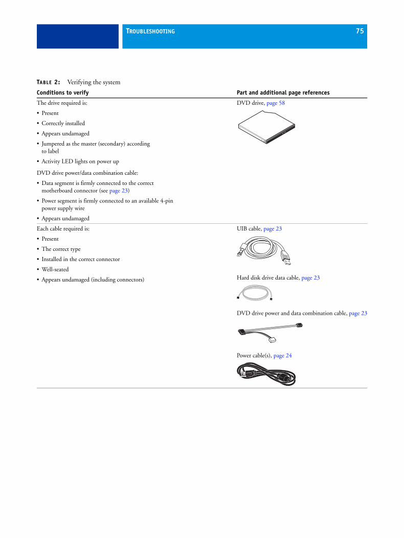
TROUBLESHOOTING 75
The drive required is:
• Present
• Correctly installed
• Appears undamaged
• Jumpered as the master (secondary) according to label
• Activity LED lights on power up
DVD drive power/data combination cable:
• Data segment is firmly connected to the correct motherboard connector (see page 23)
• Power segment is firmly connected to an available 4-pin power supply wire
• Appears undamaged
DVD drive, page 58
Each cable required is:
• Present
• The correct type
• Installed in the correct connector
• Well-seated
• Appears undamaged (including connectors)
UIB cable, page 23
Hard disk drive data cable, page 23
DVD drive power and data combination cable, page 23
Power cable(s), page 24
TABLE 2: Verifying the system
Conditions to verify Part and additional page references

TROUBLESHOOTING 76
If included in the system, the required mouse, monitor, and keyboardare present and appear undamaged. The mouse and keyboard areconnected to the correct ports on the FC Solo connector panel.
The cables required are:
• Present
• Installed in the correct connector
• Well-seated
• Appear undamaged (including connectors)
For the following items, see the document that accompanies the optional components, if applicable.
• Mouse
• Monitor
• Keyboard
• Monitor power cord (not pictured)
TABLE 2: Verifying the system
Conditions to verify Part and additional page references

TROUBLESHOOTING 77
Normal startup sequence
When you turn on or reboot the FC Solo, the system runs a startup routine. The following table lists the normal startup sequence as it appears on the FC Solo control panel and on the monitor.
FIGURE 30: Normal startup sequence
Process Control panel Monitor
FC Solo is powered on. No backlight Black screen
Code in the motherboard BIOS tests, initializes, and configures areas on the motherboard.
Lights and then displays efi|fiery logo
BIOS screen
Black screen
Windows operating system starts up.
static logo Windows logo screen
Windows Log On
Windows desktop appears after you log on with the Admin password.
Server software completes startup process.
static logo Fiery Central Bar appears with the message Starting... Please wait
static logo Fiery Central Bar indicates Idle

TROUBLESHOOTING 78
Error messages and conditionsTo address specific error messages or conditions, see “Table 3: FC Solo error messages and conditions” on page 79. Use the table to locate the problem or symptom that you want to fix, read about the possible causes, and then perform the suggested actions to solve the problem.
If replacing a component does not correct the problem, make sure that you reinstall the old component in the FC Solo.

TROUBLESHOOTING 79
TABLE 3: FC Solo error messages and conditions
Symptom Possible cause Suggested action
Beep codes during startup
1 beep No error—the FC Solo is starting up normally.
None
6 long beeps Missing, unmatched, incorrect,or faulty DIMM(s)
Check for missing, unmatched, incorrect or faulty DIMM(s) and reseat the DIMM(s) to remove any oxidation on the connector (see page 42).
Startup
FC Solo does not start and the control panel is black.
Possibly one of the following:
• Power cable is not plugged into the power connector on the FC Solo connector panel or into the wall power outlet.
• The connector panel power switch is not in the ON position and/or the internal black and white power leads from the power supply are not connected to the correct prongs on the connector panel power switch.
• UIB cable is not connected to the motherboard, the user interface board, or both.
• Faulty power cable.
• Faulty power supply (power supply may not be supplying power to the motherboard).
• The CMOS jumper is not in the default position or the CMOS needs to be cleared.
• Faulty motherboard (motherboard power plane may not be supplying power to components).
1 Recheck all cables and connections.
2 Make sure the power switch on the connector panel is in the ON position (see page 17).
3 Listen for the power supply fan and feel for air at the back of the unit where the power supply is located.
If air is not coming from the power supply fan, isolate possible faulty power cable as follows:
• Power on using a different power cable.
• Install a new or “known good” power supply.
4 Check the chassis and feel for air coming out of the back of the system.
If air is coming out of the power supply fan vent but is not coming out of the connector panel fan vent, the motherboard may be faulty. You may need to replace the motherboard (see page 33).
5 Review the jumper section on page 36 and ensure that the jumper is in the default position, then clear the CMOS.
Activity light status:Off.

TROUBLESHOOTING 80
Startup (cont.)
FC Solo is getting power, but the control panel is black.
• UIB cable is not connected to the motherboard, the User Interface Board, or both.
• Faulty UIB cable
• Faulty User Interface Board
1 Recheck all cables and connections.
2 Use a different UIB cable.
3 If the problem persists and you have verified that the power supply and the motherboard are functioning properly as described above, replace the User Interface Board (see page 31).
Following installation of a new User Interface Board, the control panel remains blank, yet backlit, for more than five minutes.
• System software requires an additional reboot to synchronize with the firmware on the new User Interface Board.
Wait 5 minutes, power off using the power button, wait 10 seconds, and then press the power button to power on again.
Control panel screen and Activity light appear as follows:
Possibly one of the following:
• Wrong, missing, incorrectly connected, or faulty DIMM(s)
• Faulty motherboard
1 Recheck all cables and connections.
2 Reboot the FC Solo.
3 If the problem persists, verify that the DIMM(s) are installed as described in the DIMM section on page 42. DIMM(s) must be installed in matching pairs in alternating sockets. Check for incorrect type, wrong capacity, missing, or faulty DIMM(s). Reseat the DIMM(s) to remove any oxidation on the connector (see page 43).
4 If the problem persists, you may need to replace the motherboard (see page 40).
Control panel screen and Activity light appear as follows:
Possibly one of the following:
• Faulty disk in the DVD drive
• Faulty motherboard
1 Reboot the FC Solo.
2 If the problem occurs when you are trying to install software from bootable media (DVD or CD), the media may be damaged. Try another DVD or CD.
3 If the problem persists, replace the motherboard.(see page 40).
Symptom Possible cause Suggested action
Activity light status:Off, then solid red.
S T A R T I N G U P. . .
Activity light status:Blinking amber,then solid red.

TROUBLESHOOTING 81
Startup (cont.)
Control panel screen and Activity light appear as follows:
Possibly one of the following:
• Faulty or incorrectly connectedhard disk drive data cable
• Hard disk drive power cable disconnected
• Faulty hard disk drive
• Faulty motherboard
1 Recheck all cables and connections. Make sure that the hard disk drive data cable is connected to SATA 1 on the motherboard (see Figure 6 on page 23).
2 Reboot the FC Solo.
3 If the problem persists, replace the hard disk drive SATA cable(see Figure 6 on page 23).
4 If the problem persists, replace the hard disk drive (see page 53).
If replacing the hard disk drive does not correct the problem, reinstall the old hard disk drive in the system.
5 If the problem persists, replace the motherboard.(see page 40).
Control panel screen and Activity light appear as follows:
Problem with the Windows operating system
1 Recheck all cables and connections.
2 Reboot the FC Solo.
3 If the problem persists, reinstall system software(see page 62).
Activity light status progresses from solid green to solid red.
Possibly one of the following:
• Problem with system software
• Print job is corrupt or too large
• Faulty UIB cable
• CPU overheated
• Faulty motherboard
1 If you suspect that the problem may be caused by a print job, try printing a different job.
2 Recheck all cables and connections.
3 Reboot the FC Solo and check whether the CPU cooling assembly fan is operating. If the fan is properly connected to the motherboard but does not operate, replace the cooling assembly.
4 If the problem persists, reinstall system software(see page 62).
5 If the problem persists, try connecting another UIB cable (see Figure 6 on page 23).
6 If the problem persists, replace the motherboard (see page 40).
Symptom Possible cause Suggested action
S T A R T I N G U P. . .
Activity light status:Blinking amber.
S T A R T I N G U P. . .
Activity light status:Blinking green, then solid red.
Activity light status:Solid green, then solid red.

TROUBLESHOOTING 82
Startup (cont.)
The system takes a long time to start up.
Possibly one of the following:
• The system may be taking longer to boot up in order to finalize installation of a patch or update.
• The hard disk drive may have fallen to the bottom of the boot order in the BIOS. This can happen if the system is powered on when the hard disk drive is missing, faulty, or not connected.
• System software may be corrupted.
1 If the slow start up happens following installation of a software patch or update, shut down, and then restart to see if the problem persists.
2 If the problem persists, make sure that the hard disk drive is present and properly connected, and then clear CMOS. When you reboot the FC Solo, the hard disk drive will be moved to the top of the boot order in the BIOS.
3 If the problem persists, reinstall system software(see page 62).
DVD drive
DVD drive is not responding, cannot be located by software, the disk will not eject, or the LED on the drive tray remains lit.
Possibly one of the following:
• A disk is stuck in the DVD drive.
• Cable connections to the DVD drive are loose or power/data combo cable is faulty.
• Faulty DVD drive
• Faulty motherboard
1 Press the eject button to open the drive tray.
2 Insert a paper clip into the small hole near the eject button to force the drive tray to open.
3 If the problem persists, check the cable connections to the DVD drive (see Figure 6 on page 23).
4 Check DVD drive data cable connection to the motherboard.
5 If the problem persists, you may need to replace the DVD drive (see page 59).
6 If the problem persists, you may need to replace the motherboard (see page 40).
System performance
System performs slowly and/or hangs periodically.
Possibly one of the following:
• Board or cable connections are loose or faulty.
• Corrupted system software
• Missing or faulty DIMM(s)
• Faulty or overheated CPU
• CMOS settings need to be reset or are corrupted.
• Faulty motherboard
1 Recheck all cables and connections.
2 Make sure that the CPU is firmly seated in its socket and that the fan cable is connected to the motherboard.
3 If the problem persists, reinstall the system software(see page 62).
4 Check for missing or faulty DIMM and reseat the DIMM to remove any oxidation on the connector (see page 43).
5 Clear the CMOS.
6 If the problem persists, you may need to replace the motherboard (see page 40).
Clock is slow. Possibly one of the following:
• CMOS settings need to be reset or are corrupted.
• Missing or dead battery on the motherboard
1 Clear the CMOS.
2 If the problem persists, replace the battery on the motherboard and then update the date and time (see page 35).
Symptom Possible cause Suggested action

TROUBLESHOOTING 83
The FC Solo hangs during system software installation.
Possibly one of the following:
• The system time and date need to be configured in the FC Solo BIOS. (If the battery was removed from the FC Solo motherboard during service and the time and date were not configured in Setup afterward, the FC Solo will hang during system software installation.)
• One of the System Software DVDs is corrupted.
• The DVD drive is faulty.
• The hard disk drive is faulty.
1 Set the time and date in the BIOS:
• Power off the FC Solo and remove any media from the DVD drive.
• If not already connected, connect a keyboard and a monitor to the FC Solo.
• Power on the FC Solo and immediately press F2 repeatedly to launch the BIOS setup utility.
• Configure the time and date. (To navigate, use the tab key and the -/+ keys).
• Save changes and exit (F10).
• When the FC Solo reaches Idle, power off and then begin a full software installation again starting with the Fiery Central System Software DVD (see page 62).
2 If the problem persists, obtain another set of System Software DVDs and begin a full software installation again starting with the Fiery Central System Software DVD.
3 If the problem persists, you may need to replace the DVD drive (see page 58).
If replacing the DVD drive does not correct the problem, reinstall the old DVD drive in the system.
4 If the problem persists, replace the hard disk drive (see page 53).
If replacing the hard disk drive does not correct the problem, reinstall the old hard disk drive in the system.
Symptom Possible cause Suggested action

TROUBLESHOOTING 84
Network
If you suspect a network problem, keep in mind the following:
• If the FC Solo does not appear on the network, there may be another device on the network with the same Ethernet hardware address.
• Conflicting network settings may have been configured for the FC Solo and the customer’s workstation.
• System software may be corrupted.
Unable to connect to the network, or the green LED on the RJ-45 network port is not lit.
Possibly one of the following:
• Network cable is connected to the wrong RJ-45 port.
• No cable/wrong type of cable is connected to the network port.
• Network cable or connectionis faulty.
• Network is faulty.
• System software is corrupted.
• Network interface on the FC Solo motherboard is faulty.
1 Make sure that a straight-through Ethernet cable is connected to the upper RJ-45 port.
2 Connect a new network cable to the (upper) RJ-45 network port.
3 If the problem persists, ask the network administrator to check Network Setup.
4 If the problem persists, make sure that the network administrator has checked other devices on the network.
If other devices are not functioning, there could be a problem with the network.
5 If the problem persists, reinstall the system software (see page 62).
Corrupt system software may cause the system to hang.
6 If the rest of the network is functioning properly and the problem persists, replace the motherboard (see page 40).
Symptom Possible cause Suggested action

TROUBLESHOOTING 85
Network (cont.)
System starts up slowly then displays one or more DHCP error messages on the control panel.
Possibly one of the following:
• Network cable is connected to the wrong RJ-45 port.
• No cable/wrong type of cable is connected to the network port.
• Network cable or connectionis faulty.
• Network is faulty.
• System searches for a nonexistent DHCP server because DHCP is enabled by default on the FC Solo, but the customer’s network is not using DHCP.
• Ethernet interface on the FC Solo motherboard is faulty.
• System software is corrupted.
1 Make sure that a straight-through Ethernet cable is connected to the upper RJ-45 port.
2 Connect a new network cable to the (upper) RJ-45 network port.
3 If the problem persists, ask the network administrator to check Network Setup.
4 If the problem persists, ask the network administrator to check other devices on the network.
If other devices are not functioning, the problem may be with the network.
5 If the problem persists, reinstall system software(see page 62).
Corrupt system software may cause the system to hang.
6 If the rest of the network is functioning properly and the problem persists, replace the motherboard (see page 40).
Symptom Possible cause Suggested action

SPECIFICATIONS 86
SPECIFICATIONS
This section provides an overview of FC Solo features, specifications, and safety certifications.
NOTE: Replacement parts and specifications are subject to change. When ordering replacement parts, refer to the current parts list maintained by your authorizedservice/support center. Install the correct parts as directed by your service/support center.
Hardware features• Single Intel Pentium dual core E5300 2.6GHz CPU
• Memory—4GB (2 x 2GB)
• An RJ-45 connector for 10BaseT/100BaseTX/1000BaseT Mbs connectivity over twisted pair cable (upper port)
• 500GB hard disk drive standard
• Built-in DVD-RW drive
Physical specifications• Operating environment:
– Temperature: +5°C to +40°C
– Relative Humidity: 10%-85% (non-condensing)
• Power supply voltage input: 100-240V @ 50-60Hz
• Power supply current input: 100V @ 2A Max.; 240V @ 4A Max.
• Dimensions (height x depth x width):
32.0 cm (12.5 in.) x 34.5 cm (15.5 in.) x 14.0 cm (5.5 in.)
• Weight: 6.8 kg (15.0 lbs.)
Safety and emissions complianceThe FC Solo has been certified to meet or surpass the following government standards.
Safety approvals EMI/EMC approvals
UL 60950-1:2007 (TUV/CU mark) FCC Class B
CAN/CSA-22.2 #60950-1-07 EN55022:2006+A1:2007-Class B
EN 60950-1 (TUV/GS mark) EN55024:1998+A1:2001 & A2:2003
CB scheme IEC 60950-1:2005 (2nd edition) AS/NZS CISPR22: 2009-Class B

INDEX 87
AAC connector 70activity light 31, 80
status during startup 81
Bbattery 33, 37, 82BIOS 37BIOS chip 40bracket
DVD drive 59, 60HDD 54, 57
buttonsdown 15, 16, 31line selection 15, 16, 31menu 16, 31up 15, 16, 31
Ccables
chassis fan 24, 50, 73CPU fan 45, 48DVD drive power/data combination 23, 24,
75HDD data 23, 55, 57, 75, 81HDD power 24, 55, 57, 75network cable, straight-through 20, 75power and reset buttons 37power supply 51UIB 23, 31, 32, 75
chassis fan 24, 50, 73checklist for service calls 61clearing the CMOS 82
after installing a new DIMM(s) 43after installing a new DVD drive 60after installing a new HDD 57to troubleshoot slow performance 82
clock 82closing the system 61CMOS 43, 57, 60, 79, 82components
checking 71exploded view of 22
configuring Fiery Central 67connections, checking 70, 71connector panel 70connectors
chassis fan 37connector panel 70CPU fan cable 37DIMMs 37DVD drive data cable 37front panel USB port 37HDD data cable 37monitor (option) 37motherboard 37network 37, 70power and reset pins on motherboard 37power supply cables 37power, AC 70UIB cable 37USB ports (dongle) 70
control panelactivity light 80buttons 16, 31using 15
cooling assembly, CPU 45covers, removing 26CPU 44–49
cooling assembly 45fan cable 45, 48removing 45replacing 46
INDEX

INDEX 88
Ddiagnostics, Ethernet address 84DIMMs
clearing CMOS after installing 43configuration 42, 86installing 43replacing 43
down button 15, 16, 31drives
DVD 58hard disk drive (HDD) 53
DVD drive 58bracket 60clearing CMOS after replacing 60power/data combination cable 23, 24, 75removing 59replacing 60
EEFI Fiery Central Bar 15
EFI Fiery Central Setup 66EFI Fiery Central License Manager 64EFI Fiery Central
licensing terms 64EMI approvals 86Ethernet
address 84connector 37
exploded view 22
Ffan
chassis 24, 50, 73CPU 45
Fiery Central software, installing 63front panel 20
removing 29
Hhard disk drive (HDD) 53, 57
bracket 54, 55, 57capacity 86caution about replacing 57clearing CMOS after replacing 57data cable 55, 57description 53mounting screws 56, 57proper handling 53removing 55replacing 57
hardware security key 65heatsink, CPU 45
JJP pins on the motherboard 36jumper pins, default configurations 36jumpers 79
LLCD 31line selection buttons 15, 16, 31
Mmemory
configuration 42, 86menu button 16, 31motherboard
battery 37battery on 33connectors 37DIMMs 42installation of 40–41jumper pins 36removal of 38–39
Nnetwork connector 37normal startup sequence 77
Oopening the system 26
Ppanels, removing 26, 29power
AC cable 70AC connector 70chassis fan 50CPU fan 45, 48DVD drive 60HDD 57
power supplycables 51removing 52replacing 53voltages 17, 86
Rreassembling the system 61reset and power buttons 18, 25, 37

INDEX 89
Ssafety approvals 86service calls
checklist 61service procedures, overview 19setup 66
access 66, 67license information 64
shutting down 18, 25side panel
removing 27replacing 27
speaker 37specifications 86startup 17
normal sequence 77straight-through network cable 20
UUIB cable 23, 31, 32, 75up button 15, 16, 31USB port 65USB ports 70user interface board (UIB)
activity light 31description 31display window 31line selection buttons 31menu button 31removing 32up/down buttons 31
Vverifying functionality 61