fieldserver x-30 start-up guide - industrial and … pin mini connector (power) (part # 59231) 2 pin...
TRANSCRIPT

A Sierra Monitor Company
APPLICABILITY & EFFECTIVITY
This manual provides instructions for the FS-B35XX-05 Models.
Please Contact FieldServer Technical Support for information on the earlier FS-B35XX-01 Model.
Effective for all systems manufactured after October 2013
FieldServer X-30 Start-Up Guide
Kernel Version: 6.11 Document Revision: 1

FS-X30 Series FieldServer Start-up Guide Table of Contents
FieldServer Technologies 1991 Tarob Court Milpitas, California 95035 USA Web: www.fieldserver.com Tel: (408) 262 2299 Fax: (408) 262 2269 Toll Free: (888) 509 1970 email: [email protected]
TABLE OF CONTENTS
1 Equipment Set-up .......................................................................................................................................... 3
1.1 Supplied equipment....................................................................................................................................... 3 1.2 Mounting ....................................................................................................................................................... 4 1.3 Dimensions .................................................................................................................................................... 5 1.4 Wiring ............................................................................................................................................................ 5 1.5 Product Specifications ................................................................................................................................... 6
2 Connection to Device ..................................................................................................................................... 6
2.1 RS-232 connection: ........................................................................................................................................ 6 2.2 RS-485 connection ......................................................................................................................................... 7 2.3 Ethernet ......................................................................................................................................................... 7
3 Operation ....................................................................................................................................................... 7
3.1 Power up the device ...................................................................................................................................... 7 3.2 Connect the PC to the FieldServer over the Ethernet port. ........................................................................... 7 3.3 Use the FieldServer Web GUI to Connect to the FieldServer ........................................................................ 8
3.3.1 Using the Discovery Tool to Allocate the IP address: ............................................................................. 8 3.4 Set IP Address of the FieldServer ................................................................................................................... 8
4 Configuring the Fieldserver .......................................................................................................................... 10
4.1 Retrieve the Sample Configuration File ....................................................................................................... 10 4.2 Change the Configuration File to Meet the Application .............................................................................. 10 4.3 Load the Updated Configuration file ........................................................................................................... 11 4.4 Test and Commission the FieldServer .......................................................................................................... 12
Appendix A. Useful Features ................................................................................................................................ 13
Appendix A.1. Enhanced Network Security ............................................................................................................. 13
Appendix B. Troubleshooting Tips ....................................................................................................................... 13
Appendix B.1. Communicating with the FieldServer over the Network .................................................................. 13 Appendix B.2. Technical Support ............................................................................................................................. 13 Appendix B.3. Connecting 2 FieldServers using the N1 and N2 Ports ..................................................................... 14
Appendix C. LED Functions ................................................................................................................................... 15
Appendix C.1. LED Identification and function ........................................................................................................ 15 Appendix C.2. LED Interpretation. ........................................................................................................................... 16
Appendix C.2.1. LonWorks® LED Interpretation ............................................................................................... 16 Appendix C.3. LED Power up sequence ................................................................................................................... 16
Appendix D. Supplied Connector Kit (FS-8915-11)................................................................................................ 17
Appendix E. Limited Warranty ............................................................................................................................. 17

FS-X30 Series FieldServer Start-up Guide Page 3 of 17
FieldServer Technologies 1991 Tarob Court Milpitas, California 95035 USA Web: www.fieldserver.com Tel: (408) 262 2299 Fax: (408) 262 2269 Toll Free: (888) 509 1970 email: [email protected]
EQUIPMENT SET-UP 1
1.1 Supplied equipment
FS-X30 Series FieldServer loaded with: Modbus RTU driver, SMT Ethernet driver and any other drivers ordered. A default configuration file has
already been loaded onto the FieldServer. Check the Driver Manual and the FieldServer
Configuration Manual for further information on this file.
USB Flash Drive loaded with: FS-X30 Series Start-up Guide
FieldServer Configuration Manual
FieldServer Utilities Manual
All FieldServer Driver Manuals
Support Utilities
Any additional folders related to special files configured for a specific FieldServer
Additional components as required - See Driver Manual Supplement for details
Accessories: DB9F/RJ45 Connection Adapter. (Part # FS-8917-02)
Adapter for hyperterminal connection to the Sys Port (Part # FS8917-26)
Power Supply (Part # 69196)
Detachable Power Cord (Part # 53029)
7 pin mini connector (RS-485) (Part # 59232)
5 pin mini connector (Power) (Part # 59231)
2 pin mini connector – High Temp (LonWorks® connection) (Part # 59230)
Self-Adhesive feet (Part # 69178)
Small accessory kit containing four unpinned DB9 connectors (Part # 8915-11)
.

FS-X30 Series FieldServer Start-up Guide Page 4 of 17
FieldServer Technologies 1991 Tarob Court Milpitas, California 95035 USA Web: www.fieldserver.com Tel: (408) 262 2299 Fax: (408) 262 2269 Toll Free: (888) 509 1970 email: [email protected]
1.2 Mounting
The following mounting options are available: Wall or panel
Free standing or table
DIN rail (Part # FS-8915-30). Not included.
Figure 1: FieldServer FS-X30 Series showing DIN mounting option.
FS-X30 Series FieldServer Start-up Guide Page 5 of 17
FieldServer Technologies 1991 Tarob Court Milpitas, California 95035 USA Web: www.fieldserver.com Tel: (408) 262 2299 Fax: (408) 262 2269 Toll Free: (888) 509 1970 email: [email protected]
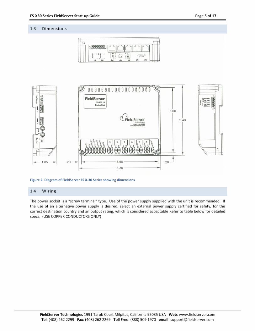
1.3 Dimensions
Figure 2: Diagram of FieldServer FS X-30 Series showing dimensions
1.4 Wiring
The power socket is a “screw terminal” type. Use of the power supply supplied with the unit is recommended. If the use of an alternative power supply is desired, select an external power supply certified for safety, for the correct destination country and an output rating, which is considered acceptable Refer to table below for detailed specs. (USE COPPER CONDUCTORS ONLY)
FS-X30 Series FieldServer Start-up Guide Page 6 of 17
FieldServer Technologies 1991 Tarob Court Milpitas, California 95035 USA Web: www.fieldserver.com Tel: (408) 262 2299 Fax: (408) 262 2269 Toll Free: (888) 509 1970 email: [email protected]
1.5 Product Specifications
Power requirements:
24 VAC (+/- 10%) and 12-30 VDC, 12W USE COPPER CONDUCTORS ONLY
Physical Dimensions(excluding the external power supply)
(WxDxH): 6.3 x 5.4 x 1.95 inches (16 x 13.7 x 5 cm)
Weight: 2.5 lbs. (1.5 Kg)
Available Ports
2 x 10/100 BaseT Ethernet connectors (auto sensing) with ESD Protection – N1, N2. Ethernet ports are not networked together. 2 x RJ45 RS-232 connectors – P1, P2 – both galvanically isolated with ESD protection. 1 x RJ45 RS-232 System port –Sys - For FieldServer diagnostic use only. 2 x RS-485 Serial connectors; R1, R2 – both galvanically isolated with ESD protection. 1 x LonWorks® connector Auxiliary components: 2x USB Host (Type A) connectors which can be used to update the Firmware and Configuration File, Linux Kernel and Flash File system. Node ID selectors and LonWorks® Service button are available for those drivers requiring these features. See appropriate driver manual. For more information refer to Enote0092. Fieldbus: Fieldbus connectors available on selected gateways.
Environment:
Operating Temperature: 0 – 60°C (32 – 140°F)
Humidity: 10 - 90% RH (non-condensing)
Approvals:
BTL Pending UL Pending LonWorks® Pending CE Pending FCC Part 15 Pending
(Specifications subject to change without notice)
CONNECTION TO DEVICE 2
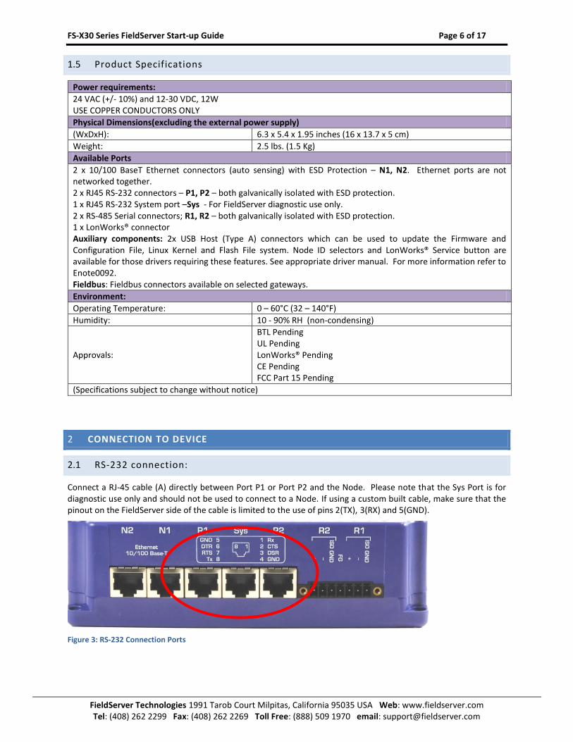
2.1 RS-232 connection:
Connect a RJ-45 cable (A) directly between Port P1 or Port P2 and the Node. Please note that the Sys Port is for diagnostic use only and should not be used to connect to a Node. If using a custom built cable, make sure that the pinout on the FieldServer side of the cable is limited to the use of pins 2(TX), 3(RX) and 5(GND).
Figure 3: RS-232 Connection Ports

FS-X30 Series FieldServer Start-up Guide Page 7 of 17
FieldServer Technologies 1991 Tarob Court Milpitas, California 95035 USA Web: www.fieldserver.com Tel: (408) 262 2299 Fax: (408) 262 2269 Toll Free: (888) 509 1970 email: [email protected]
2.2 RS-485 connection
If using RS-485 from the node to the FS-X30, the + , – and GND wire connections can be used on the RS-485 port on the FieldServer.
Figure 4: RS-485 Connection Ports
2.3 Ethernet
The Ethernet ports support Auto-MDIX. The provided Cat5 UTP Ethernet cable can be used to connect the FieldServer to a hub/switch or directly to the device through these ports.
Figure 5: Ethernet Connection Ports
OPERATION 3
3.1 Power up the device
Apply power to the device. Ensure that the power supply used
complies with the specifications provided in Section 1.5.
The power light should burn a steady green when the FieldServer
is powered up. Refer to 0 for more information on the
various LED functions.
3.2 Connect the PC to the FieldServer over the Ethernet port.
The Ethernet ports support Auto-MDIX. The provided Cat5 UTP Ethernet cable can be used to connect the
FieldServer to a hub/switch or directly to the device through either of the N1 or N2 ports..
Disable any wireless Ethernet adapters on the PC/Laptop,
It is important that the PC/Laptop is on the same subnet as the FieldServer.
If connecting 2 FieldServers together using the N1 and N2 ports, please note that the ports need to be on
different subnets. The default IP address on the FieldServer N1 port is 192.168.2.X and the N2 port is
192.168.3.X. Refer to Appendix B.3 and the FieldServer Utilities Manual.
FS-X30 Series FieldServer Start-up Guide Page 8 of 17
FieldServer Technologies 1991 Tarob Court Milpitas, California 95035 USA Web: www.fieldserver.com Tel: (408) 262 2299 Fax: (408) 262 2269 Toll Free: (888) 509 1970 email: [email protected]
3.3 Use the FieldServer Web GUI to Connect to the FieldServer
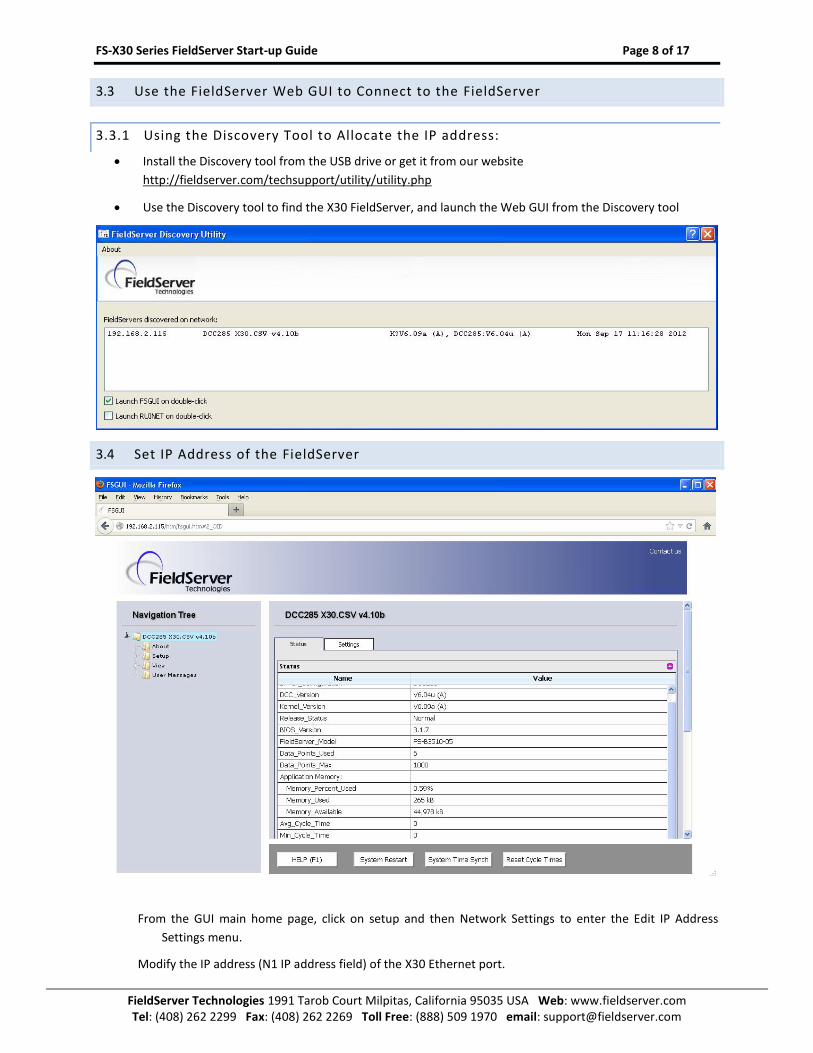
3.3.1 Using the Discovery Tool to Allocate the IP address:
Install the Discovery tool from the USB drive or get it from our website
http://fieldserver.com/techsupport/utility/utility.php
Use the Discovery tool to find the X30 FieldServer, and launch the Web GUI from the Discovery tool
3.4 Set IP Address of the FieldServer
From the GUI main home page, click on setup and then Network Settings to enter the Edit IP Address
Settings menu.
Modify the IP address (N1 IP address field) of the X30 Ethernet port.

FS-X30 Series FieldServer Start-up Guide Page 9 of 17
FieldServer Technologies 1991 Tarob Court Milpitas, California 95035 USA Web: www.fieldserver.com Tel: (408) 262 2299 Fax: (408) 262 2269 Toll Free: (888) 509 1970 email: [email protected]
If necessary, change the Netmask (N1 Netmask field).
Type in a new Subnet Mask
If necessary, change the IP Gateway (Default Gateway field)
Type in a new IP Gateway
Note: If the FieldServer is connected to a router, the IP Gateway of the FieldServer should be set to the IP
address of the router that it is connected to
Click Update IP Settings, then click on the System Restart to restart the Gateway and activate the new IP
address. Note that the FieldServer will need to be pointed to the new IP address on the Web Browser
before the GUI will be accessible again. Unplug Ethernet cable from PC and connect it to the network
hub or router

FS-X30 Series FieldServer Start-up Guide Page 10 of 17
FieldServer Technologies 1991 Tarob Court Milpitas, California 95035 USA Web: www.fieldserver.com Tel: (408) 262 2299 Fax: (408) 262 2269 Toll Free: (888) 509 1970 email: [email protected]
CONFIGURING THE FIELDSERVER 4
4.1 Retrieve the Sample Configuration File
The configuration of the FieldServer is provided to the FieldServer’s operating system via a comma-delimited file called “CONFIG.CSV”.
If a custom configuration was ordered, the FieldServer will be programmed with the relevant device registers in the Config.csv file for the first time start-up. If not, the product is shipped with a sample config.csv that shows an example of the drivers ordered.
In the main menu of the FS-GUI screen, go to Setup, File Transfer, Retrieve.
Click on config.csv, and open or save the file
4.2 Change the Configuration File to Meet the Application
Refer to the FieldServer Configuration Manual in conjunction with the Driver supplements for information on configuring the FieldServer.

FS-X30 Series FieldServer Start-up Guide Page 11 of 17
FieldServer Technologies 1991 Tarob Court Milpitas, California 95035 USA Web: www.fieldserver.com Tel: (408) 262 2299 Fax: (408) 262 2269 Toll Free: (888) 509 1970 email: [email protected]
4.3 Load the Updated Configuration file
In the main menu of the FS-GUI screen, go to Setup, File Transfer, Update
Browse and select the .csv file, open, then click Submit
Once download is complete, click the System Restart Button (or simply cycle power to the FieldServer) to
put the new file into operation. Note that it is possible to do multiple downloads to the FieldServer
before resetting it.

FS-X30 Series FieldServer Start-up Guide Page 12 of 17
FieldServer Technologies 1991 Tarob Court Milpitas, California 95035 USA Web: www.fieldserver.com Tel: (408) 262 2299 Fax: (408) 262 2269 Toll Free: (888) 509 1970 email: [email protected]
4.4 Test and Commission the FieldServer
Connect the FieldServer to the third party device(s), and test the application.
From the main menu of FS-GUI click on View, Connections to see the number of messages on each
protocol.
For troubleshooting assistance refer to Appendix A, or any of the troubleshooting Appendices in the
related Driver Supplements and Configuration Manual. FieldServer Technologies also offers a
Technical support page on the FieldServer website at www.FieldServer.com, which contains a
significant number of resources and documentation that may be of assistance.
FS-X30 Series FieldServer Start-up Guide Page 13 of 17
FieldServer Technologies 1991 Tarob Court Milpitas, California 95035 USA Web: www.fieldserver.com Tel: (408) 262 2299 Fax: (408) 262 2269 Toll Free: (888) 509 1970 email: [email protected]
Appendix A. USEFUL FEATURES
Appendix A.1. Enhanced Network Security
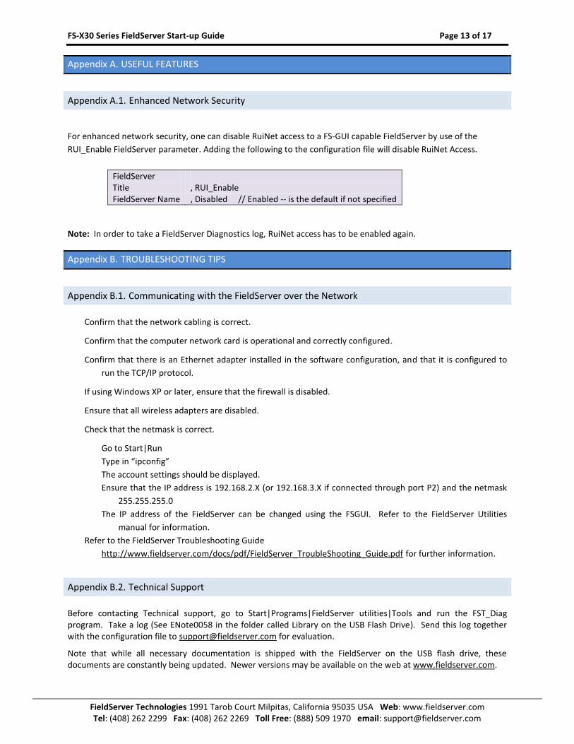
For enhanced network security, one can disable RuiNet access to a FS-GUI capable FieldServer by use of the
RUI_Enable FieldServer parameter. Adding the following to the configuration file will disable RuiNet Access.
FieldServer Title , RUI_Enable FieldServer Name , Disabled // Enabled -- is the default if not specified
Note: In order to take a FieldServer Diagnostics log, RuiNet access has to be enabled again.
Appendix B. TROUBLESHOOTING TIPS
Appendix B.1. Communicating with the FieldServer over the Network
Confirm that the network cabling is correct.
Confirm that the computer network card is operational and correctly configured.
Confirm that there is an Ethernet adapter installed in the software configuration, and that it is configured to
run the TCP/IP protocol.
If using Windows XP or later, ensure that the firewall is disabled.
Ensure that all wireless adapters are disabled.
Check that the netmask is correct.
Go to Start|Run
Type in “ipconfig”
The account settings should be displayed.
Ensure that the IP address is 192.168.2.X (or 192.168.3.X if connected through port P2) and the netmask
255.255.255.0
The IP address of the FieldServer can be changed using the FSGUI. Refer to the FieldServer Utilities
manual for information.
Refer to the FieldServer Troubleshooting Guide
http://www.fieldserver.com/docs/pdf/FieldServer_TroubleShooting_Guide.pdf for further information.
Appendix B.2. Technical Support
Before contacting Technical support, go to Start|Programs|FieldServer utilities|Tools and run the FST_Diag program. Take a log (See ENote0058 in the folder called Library on the USB Flash Drive). Send this log together with the configuration file to [email protected] for evaluation.
Note that while all necessary documentation is shipped with the FieldServer on the USB flash drive, these documents are constantly being updated. Newer versions may be available on the web at www.fieldserver.com.

FS-X30 Series FieldServer Start-up Guide Page 14 of 17
FieldServer Technologies 1991 Tarob Court Milpitas, California 95035 USA Web: www.fieldserver.com Tel: (408) 262 2299 Fax: (408) 262 2269 Toll Free: (888) 509 1970 email: [email protected]
Appendix B.3. Connecting 2 FieldServers using the N1 and N2 Ports
When connecting FieldServers together using the N1 and N2 ports, the ports need to be on different subnets. Refer to the FieldServer Utilities manual for information on using FSGUI to set new IP_Addresses for N2 on both FieldServers.
The address N2 = 192.168.3.29 is suggested. This address will not appear on the general network so it could really be anything.
The IP_Address on the appropriate Node must also be changed in the configuration as detailed below:
Nodes Node_Name , Node_ID , Protocol , Adapter , IP_Address PLC_01 , 1 , Modbus/TCP , N2 , 192.168.3.29
FS-X30 Series FieldServer Start-up Guide Page 15 of 17
FieldServer Technologies 1991 Tarob Court Milpitas, California 95035 USA Web: www.fieldserver.com Tel: (408) 262 2299 Fax: (408) 262 2269 Toll Free: (888) 509 1970 email: [email protected]
Appendix C. LED FUNCTIONS
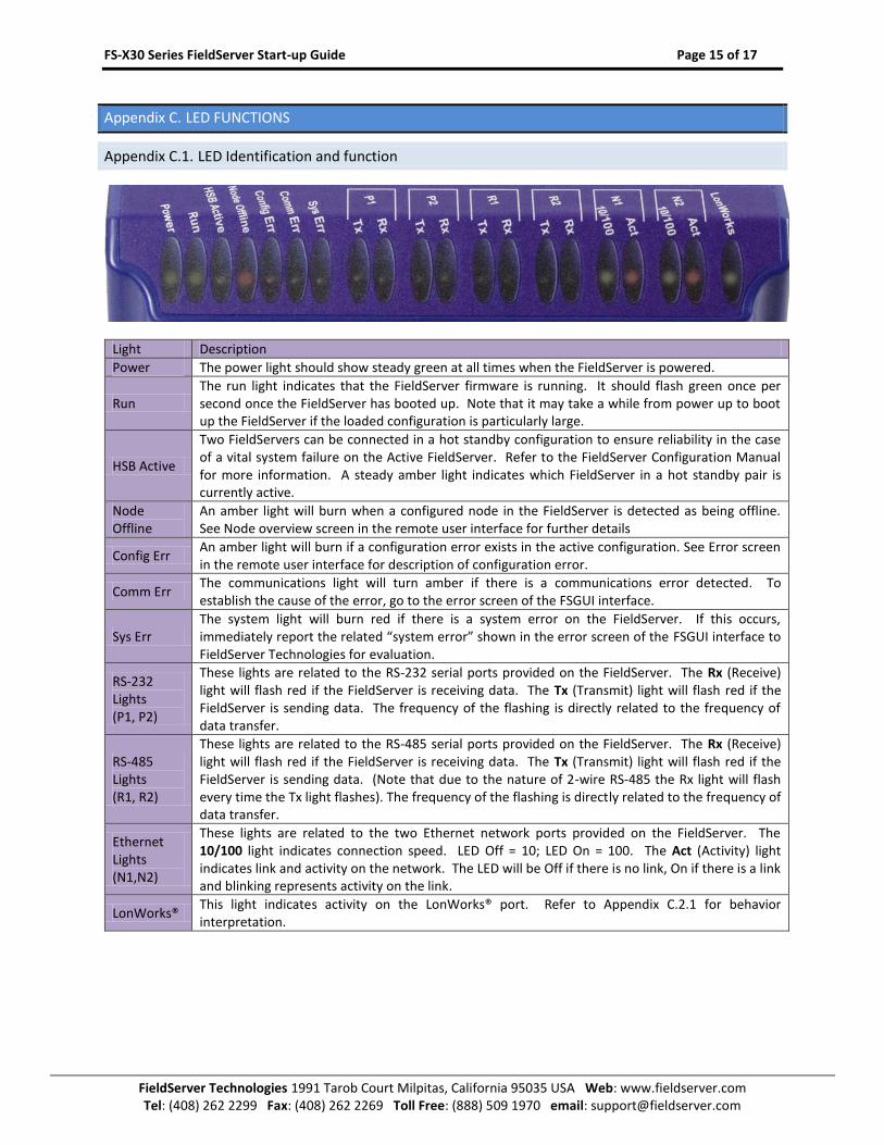
Appendix C.1. LED Identification and function
Light Description
Power The power light should show steady green at all times when the FieldServer is powered.
Run The run light indicates that the FieldServer firmware is running. It should flash green once per second once the FieldServer has booted up. Note that it may take a while from power up to boot up the FieldServer if the loaded configuration is particularly large.
HSB Active
Two FieldServers can be connected in a hot standby configuration to ensure reliability in the case of a vital system failure on the Active FieldServer. Refer to the FieldServer Configuration Manual for more information. A steady amber light indicates which FieldServer in a hot standby pair is currently active.
Node Offline
An amber light will burn when a configured node in the FieldServer is detected as being offline. See Node overview screen in the remote user interface for further details
Config Err An amber light will burn if a configuration error exists in the active configuration. See Error screen in the remote user interface for description of configuration error.
Comm Err The communications light will turn amber if there is a communications error detected. To establish the cause of the error, go to the error screen of the FSGUI interface.
Sys Err The system light will burn red if there is a system error on the FieldServer. If this occurs, immediately report the related “system error” shown in the error screen of the FSGUI interface to FieldServer Technologies for evaluation.
RS-232 Lights (P1, P2)
These lights are related to the RS-232 serial ports provided on the FieldServer. The Rx (Receive) light will flash red if the FieldServer is receiving data. The Tx (Transmit) light will flash red if the FieldServer is sending data. The frequency of the flashing is directly related to the frequency of data transfer.
RS-485 Lights (R1, R2)
These lights are related to the RS-485 serial ports provided on the FieldServer. The Rx (Receive) light will flash red if the FieldServer is receiving data. The Tx (Transmit) light will flash red if the FieldServer is sending data. (Note that due to the nature of 2-wire RS-485 the Rx light will flash every time the Tx light flashes). The frequency of the flashing is directly related to the frequency of data transfer.
Ethernet Lights (N1,N2)
These lights are related to the two Ethernet network ports provided on the FieldServer. The 10/100 light indicates connection speed. LED Off = 10; LED On = 100. The Act (Activity) light indicates link and activity on the network. The LED will be Off if there is no link, On if there is a link and blinking represents activity on the link.
LonWorks® This light indicates activity on the LonWorks® port. Refer to Appendix C.2.1 for behavior interpretation.

FS-X30 Series FieldServer Start-up Guide Page 16 of 17
FieldServer Technologies 1991 Tarob Court Milpitas, California 95035 USA Web: www.fieldserver.com Tel: (408) 262 2299 Fax: (408) 262 2269 Toll Free: (888) 509 1970 email: [email protected]
Appendix C.2. LED Interpretation.
Sys Err
HSB Active
Com Err
Config Err
Active Node Offline
Run PWR Description
FLASH ON Indicating Power
ON FLASH ON One of the configured nodes is offline.
ON FLASH ON FieldServer is active in a Hot Standby configuration.
ON FLASH ON System Error. Contact FieldServer Technologies
OFF FLASH ON RELEASE DCC running
ON FLASH ON Configuration error.
FLASH FLASH ON Demo Mode
OFF OFF OFF OFF OFF OFF
No power OR if the lights flash every few minutes intermittently between all LED's off, then FieldServer is continuously rebooting.
Appendix C.2.1. LonWorks® LED Interpretation
Explicit Implicit – Not Commissioned Implicit – Commissioned
Off Flashing Off
Appendix C.3. LED Power up sequence
Start-up: All LED’s on.
Load Bios: Run LED will switch off after completion..
Load U-boot: HSB Active LED will switch off after completion
Load Linux Kernel: Node Offline LED will swich off after completion
Load Ethernet driver: Config LED will switch off after completion.
Load Flash File: Sys LED will switch off after completion.
Load Application Firmware:Sys Error LED will switch off after completion.

FS-X30 Series FieldServer Start-up Guide Page 17 of 17
FieldServer Technologies 1991 Tarob Court Milpitas, California 95035 USA Web: www.fieldserver.com Tel: (408) 262 2299 Fax: (408) 262 2269 Toll Free: (888) 509 1970 email: [email protected]
Appendix D. SUPPLIED CONNECTOR KIT (FS-8915-11)
The following connector is supplied to facilitate RS-232 communications on the RJ-45 RS-232 port. The table in the diagram shows the functions applied to each of the RJ-45 pins by the FieldServer to assist in determination of the required pinout configuration for connection to the third party device. Note that FS-X30 Series RS-232 numbering convention is reverse to the 10BaseT numbering
FS-8917-02
WIRE LIST
Figure 6: FieldServer Connector Reference
Appendix E. LIMITED WARRANTY
FieldServer Technologies warrants its products to be free from defects in workmanship or material under normal use and service for two years after date of shipment. FieldServer Technologies will repair or replace without charge any equipment found to be defective during the warranty period. Final determination of the nature and responsibility for defective or damaged equipment will be made by FieldServer Technologies personnel.
All warranties hereunder are contingent upon proper use in the application for which the product was intended and do not cover products which have been modified or repaired without FieldServer Technologies approval or which have been subjected to accident, improper maintenance, installation or application, or on which original identification marks have been removed or altered. This Limited Warranty also will not apply to interconnecting cables or wires, consumables or to any damage resulting from battery leakage.
In all cases FieldServer Technology’s responsibility and liability under this warranty shall be limited to the cost of the equipment. The purchaser must obtain shipping instructions for the prepaid return of any item under this warranty provision and compliance with such instruction shall be a condition of this warranty.
Except for the express warranty stated above, FieldServer Technologies disclaims all warranties with regard to the products sold hereunder including all implied warranties of merchantability and fitness and the express warranties stated herein are in lieu of all obligations or liabilities on the part of FieldServer Technologies for damages including, but not limited to, consequential damages arising out of/or in connection with the use or performance of the product.