fielding a structural health monitoring system on … · a business perspective unclassified...
TRANSCRIPT

Fielding a Structural Health Monitoring system on legacy military aircraft
A business perspective
C u s t o m e r
Defence Materiel Organisation
NLR-TP-2014-296 - September 2014

N a t i o n a l A e r o s p a c e L a b o r a t o r y N L R
A n t h o n y F o k k e r w e g 2
1 0 5 9 C M A m s t e r d a m
T h e N e t h e r l a n d s
T e l + 3 1 ( 0 ) 8 8 5 1 1 3 1 1 3
w w w . n l r . n l

UNCLASSIFIED
EXECUTIVE SUMMARY
UNCLASSIFIED
Report no. NLR-TP-2014-296 Author(s) M.J. Bos Report classification UNCLASSIFIED Date September 2014 Knowledge area(s) Health Monitoring & Maintenance of Aircraft Descriptor(s) Structural Health Monitoring Military aircraft Condition Based Maintenance Certification Business Case
This report is based on a presentation held at the 2nd
International Conference on Advances in Structural Health Management and Composite Structures in Jeonju, South Korea, August 27-29, 2014.
Fielding a Structural Health Monitoring system on legacy military aircraft A business perspective
Example of a Structural Health Monitoring system: Comparative Vacuum
Monitoring as applied during a full-scale fatigue test on an F-16 wing.
Executive summary
The sustainment costs of military aircraft constitute a substantial
part of the total life cycle costs, which implies that the application
of innovative methods and technologies in the sustainment
process may lead to large cost savings. An important trend in this
respect is the transition from preventative maintenance to
Condition Based Maintenance (CBM). For CBM it is essential that
the actual system condition can be measured and that the
measured condition can be reliably extrapolated to a convenient
moment in the future in order to facilitate the planning process
while maintaining flight safety. Much research effort is currently
being put in the development of technologies that enable CBM,
Fielding a Structural Health Monitoring system on legacy military aircraft
A business perspective UNCLASSIFIED
National Aerospace Laboratory NLR Anthony Fokkerweg 2, 1059 CM Amsterdam, P.O. Box 90502, 1006 BM Amsterdam, The Netherlands Telephone +31 (0)88 511 31 13, Fax +31 (0)88 511 32 10, Website: www.nlr.nl UNCLASSIFIED
among which Structural Health Monitoring (SHM) systems. Good
progress has already been booked when it comes to sensors,
sensor networks, data acquisition, models and algorithms, data
fusion/mining techniques, etc. However, the transition of these
technologies into service is very slow. Reasons are that business
cases are difficult to define and that certification of SHM systems
is very challenging.
This paper describes a possibility for fielding a SHM system on
legacy military aircraft with a minimum amount of certification
issues and with a good prospect of a positive return on
investment. For appropriate areas in the airframe the application
of SHM will reconcile the fail-safety and slow crack growth
damage tolerance approaches that can be used for safeguarding
the continuing airworthiness of these areas, combining the
benefits of both approaches and removing the drawbacks

Fielding a Structural Health Monitoring system on legacy military aircraft A business perspective
M.J. Bos
C u s t o m e r
Defence Materiel Organisation September 2014

Fielding a Structural Health Monitoring system on legacy military aircraft
A business perspective
2 | NLR-TP-2014-296
This report is based on a presentation held at the 2nd
International Conference on Advances in Structural
Health Management and Composite Structures in Jeonju, South Korea, August 27-29, 2014.
The contents of this report may be cited on condition that full credit is given to NLR and the authors.
This publication has been refereed by the Advisory Committee AEROSPACE VEHICLES.
Customer Defence Materiel Organisation
Contract number L1414/15
Owner NLR
Division NLR Aerospace Vehicles
Distribution Unlimited
Classification of title Unclassified
Date September 2014
Approved by:
Author
M.J. Bos
Reviewer
F.C. te Winkel
Managing department
A.M. Vollebregt
Date Date Date

NLR-TP-2014-296 | 3
Summary
The transition of Structural Health Monitoring (SHM) technologies into service is
very slow. Reasons are that business cases are difficult to define and that
certification of SHM systems is very challenging.
This paper describes a possibility for fielding a SHM system on legacy military aircraft with a
minimum amount of certification issues and with a good prospect of a positive return on
investment.

Fielding a Structural Health Monitoring system on legacy military aircraft
A business perspective
4 | NLR-TP-2014-296
Source: Ministerie van Defensie

NLR-TP-2014-296 | 5
Content
Abbreviations ..................................................................................... 6
1 Introduction ................................................................................. 7
2 Structural integrity concepts of military aircraft ........................... 8
3 Potential SHM business case ...................................................... 13
4 Conclusion .................................................................................. 14
5 References ................................................................................. 16

Fielding a Structural Health Monitoring system on legacy military aircraft
A business perspective
6 | NLR-TP-2014-296
Abbreviations
Acronym Description
ac Critical fatigue crack size
ad Detectable fatigue crack size
ai Initial fatigue crack size
ASIP Aircraft Structural Integrity Program
CBM Condition Based Maintenance
CVM Comparative Vacuum Monitoring
DLL Design Limit Load
FS Fuselage Station
NDI Non-Destructive Inspection
NLR National Aerospace Laboratory
POD Probability Of Detection
SHM Structural Health Monitoring
SOF Safety Of Flight
Tc Time of failure
Ti Time of initial inspection
TRL Technology Readiness Level
USAF United States Air Force
Tr Recurring inspection interval

NLR-TP-2014-296 | 7
1 Introduction
Military operators worldwide are looking for ways and means to maintain or even improve the
availability and continuing airworthiness of their fleets of aircraft while decreasing the cost of
ownership. The sustainment costs of military aircraft constitute a substantial part of the total life
cycle costs (typically in the order of two-thirds), which implies that the application of innovative
methods and technologies in the sustainment process may lead to large cost savings. An
important trend in this respect, especially within the USAF, US Navy and US Army but also within
the aerospace industry, is the transition from preventative maintenance – based on calendar
time, flight hours or flight cycles – to Condition Based Maintenance (CBM). Maintenance is then
only performed when needed, which is expected to lead to a significant cost reduction. For CBM
it is essential that the actual system condition can be measured (diagnostics) and that the
measured condition can be reliably extrapolated (prognostics) to a convenient moment in the
future in order to facilitate the planning process while maintaining flight safety. Much research
effort is currently being put in the development of technologies that enable CBM, among which
Structural Health Monitoring (SHM) systems. Good progress has already been booked when it
comes to sensors, sensor networks, data acquisition, models and algorithms, data fusion/mining
techniques, etc. However, the transition of these technologies into service is very slow. There are
two reasons for this:
Business Cases are difficult to define since CBM represents a disruptive technology that
produces a paradigm shift for maintenance support [1];
Certification is difficult as the validation of the SHM system’s capability to reliably and
accurately detect impending in-service failures is extremely challenging; in addition, the
procedures for obtaining maintenance credits are still being developed.
One option to validate the performance of a particular SHM system is to use a seeded fault test.
This requires a hi-fidelity and expensive test bench and a good a priori knowledge of the location
and the nature of the failure modes that are to be detected. An alternative is to field the SHM
system in a sufficient number of aircraft and evaluate its performance after a sufficient number
of flight cycles. ‘Sufficient’ in this respect is indeterminate and may cover a significant part of the
service life in order to be able to collect relevant data. This, of course, is undesirable. Fortunately
there are some special cases where certification of a SHM system for use in military aircraft is
much easier. This paper describes such a case. It forms an opportunity to field a SHM system on
legacy military aircraft such as the F-16 with a minimum amount of certification issues and with a
good prospect of a positive return on investment. Seizing it would be an evolutionary step
towards more challenging applications.

Fielding a Structural Health Monitoring system on legacy military aircraft
A business perspective
8 | NLR-TP-2014-296
2 Structural integrity concepts of military aircraft
The formation and growth of fatigue cracks is still considered to be the major threat to the
structural safety and continuing airworthiness of military combat and transport aircraft [2]. To
guard against the detrimental effects of structural fatigue, a number of design and maintenance
concepts have been evolved over the years. Two philosophies are currently in use, viz. the safe
life concept, which precludes the presence of fatigue cracks, and the damage tolerance concept,
in which fatigue cracks and other flaws that are assumed to be present from day one should not
grow to a critical size within a reasonable period (e.g. lifetime or inspection interval), in order to
allow for timely detection and repair. The initial USAF damage tolerance requirements were
introduced in 1974, in MIL-A-83444 [3], and the F-16 is the first fighter aircraft that has been
designed and certified to this specification. MIL-A-83444 allowed the use of either fail-safe or
slow crack growth design concepts. The focus for the F-16 and other contemporary fighters was
on slow crack growth however, since most combat aircraft were designed with many single load
path structures and in its original form the MIL-A-83444 requirements tended to discourage the
application of fail-safety [4]. With the slow crack growth concept it is mandatory that material,
manufacturing and/or service induced defects not be allowed to grow to their critical crack sizes
before they are detected and repaired. The slow crack growth damage tolerance concept
therefore only provides safety if it incorporates a rigorous inspection program. Conservative
initial crack sizes were specified in MIL-A-83444 and later in the Joint Services Specification
Guide, JSSG-2006 [5], and Structures Bulletin EN-SB-08-002 [6] for use in design and in
establishing inspection requirements. A typical value is 1.27 mm (or 0.05”) for a corner crack that
is to represent a flaw (i.e. manufacturing defect, material defect, corrosion pit, maintenance
induced damage, etc.) that is assumed to be present at the most critical location (e.g. a fastener
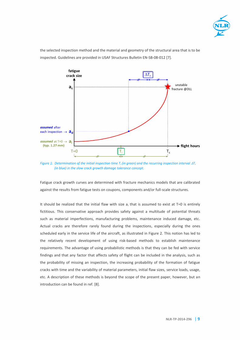
hole) in a flight critical structural item. The required time Ti for the initial inspection is then
determined by dividing the time that it takes for a fatigue crack to grow from its initial size a i to
its critical size ac by a safety or scatter factor of two, where ac is the crack size at which design
limit load (DLL) will lead to unstable fracture. This is schematically shown in Figure 1. This figure
also shows how the recurring inspection interval Tr is determined. The recurring inspection
interval is generally shorter than the time to initial inspection since it is based on the safe crack
growth life of an in-service detectable flaw with size ad, which depends on the inspection method
that is used (visual, eddy current, etc.), the location in the aircraft (easy access or not, lighting
conditions), the presence of fastener heads that block the view on the crack, etc. The minimum
detectable flaw sizes used in the establishment of the recurring inspection intervals should be
based on experimentally determined probability of detection (POD) curves that are relevant for
NLR-TP-2014-296 | 9
the selected inspection method and the material and geometry of the structural area that is to be
inspected. Guidelines are provided in USAF Structures Bulletin EN-SB-08-012 [7].
Figure 1: Determination of the initial inspection time Ti (in green) and the recurring inspection interval Tr
(in blue) in the slow crack growth damage tolerance concept.
Fatigue crack growth curves are determined with fracture mechanics models that are calibrated
against the results from fatigue tests on coupons, components and/or full-scale structures.
It should be realized that the initial flaw with size ai that is assumed to exist at T=0 is entirely
fictitious. This conservative approach provides safety against a multitude of potential threats
such as material imperfections, manufacturing problems, maintenance induced damage, etc.
Actual cracks are therefore rarely found during the inspections, especially during the ones
scheduled early in the service life of the aircraft, as illustrated in Figure 2. This notion has led to
the relatively recent development of using risk-based methods to establish maintenance
requirements. The advantage of using probabilistic methods is that they can be fed with service
findings and that any factor that affects safety of flight can be included in the analysis, such as
the probability of missing an inspection, the increasing probability of the formation of fatigue
cracks with time and the variability of material parameters, initial flaw sizes, service loads, usage,
etc. A description of these methods is beyond the scope of the present paper, however, but an
introduction can be found in ref. [8].

Fielding a Structural Health Monitoring system on legacy military aircraft
A business perspective
10 | NLR-TP-2014-296
Figure 2: In-service inspections for fatigue cracks. After each inspection the size of the assumed analytical
crack is reset to its in-service detectable size ad.
Be that as it may, the USAF have recently revised the original MIL-A-83444 fail-safe requirements
in an attempt to encourage fail-safe design and certification of future military aircraft as well as
provide the basis for fail-safe assessments of legacy aircraft. Although no military aircraft has
been designed and certified to the MIL-A-83444 fail-safe requirements, most of these aircraft do
feature some fail-safety through the use of multiple redundant load paths. In a fail-safe structure
a primary component is allowed to completely or partially fail, provided that the residual
strength of the adjacent secondary structural elements is sufficient to sustain critical design limit
load conditions and that the failure of the primary load path is either readily detectable during a
scheduled visual inspection (so not NDI) or malfunction evident, meaning a failure would result in
the malfunction of other systems (e.g. fuel leakage or pressure loss) that would alert the flight or
ground personnel to the existence of the failure. “Readily detectable” could also mean that the
failure is apparent from in-flight or post flight visual observations. The new fail-safe requirements
are laid down in Structures Bulletin EN-SB-08-001 [9]. Some of the MIL-A-83444 requirements
that discouraged the application of fail-safety, such as the stipulation of dependent load paths
[4], have been removed and also the definition of the fail-safety life limit has been revised and in
general the life limit is now longer than the one defined in MIL-A-83444.
There were a number of reasons to promote fail-safety and revise the criteria:
Fail-safety provides protection against all forms of damage an aircraft may encounter in
its lifetime (incl. battle damage and discrete source damage due to bird strike,
uncontained engine disk failures, etc.) instead of fatigue damage only.
The minimum in-service detectable flaw sizes as specified in USAF Structures Bulletin
EN-SB-08-012 issued in 2013 are generally larger than what was assumed previously. For
legacy aircraft such as the F-16, that has many structural areas with small critical crack

NLR-TP-2014-296 | 11
sizes, this has led to revised recurring inspection intervals for slow crack growth damage
tolerant structure which, in some cases, were unacceptably short or even zero.
Fail-safe damage tolerance structure only needs to be inspected visually, which entails a
very limited maintenance burden. Identification of those safety-of-flight (SOF) locations
which have inherent fail-safe capability, and classifying these locations as such, will
allow relaxation of the current inspection burden by focusing special non-destructive
inspections (NDI) on only those SOF locations which are not fail-safe. This will entail
significant cost reductions and it will lead to an increase of aircraft safety, availability
and readiness, especially for aging fleets.
NDI often requires the removal of sealant and/or fasteners. By doing so damage may
inadvertently be inflicted to the SOF locations in question. Scratches and dents are often
the precursors to fatigue cracks. Fail-safe damage tolerance structure only needs to be
inspected visually, with less associated risk of inflicting damage to critical structure.
Fail-safety can also assist when areas are inaccessible or not practical to inspect regularly [10]. An
example is provided in Figure 3, which shows the F-16 fuel shelf of which the joint bolt holes in
the upper wing carry-through bulkhead at fuselage station FS 341 are fracture critical.
Figure 3: Difficult access to the fracture critical F-16 fuel shelf joint bolt holes at FS341 (left). Visual
inspection for large cracks in flanges and web of the upper bulkhead is much easier (right) [10].
When managed using slow crack growth damage tolerance, the joint bolts need to be removed
during depot level maintenance to enable the bolt hole eddy current inspection that is required
for the detection of small cracks. This is very difficult and often damage is induced. Managing this

Fielding a Structural Health Monitoring system on legacy military aircraft
A business perspective
12 | NLR-TP-2014-296
area using fail-safety and visual inspection for fuel leaks or for large cracks in the flanges or webs
of the upper bulkhead is much easier and does not require specialized technicians and tools.
For this particular case it has been shown by the aircraft manufacturer that if the lower flange
and web at the fuel shelf joint bolt hole of the upper FS 341 bulkhead fail, limit load can indeed
be carried by the adjacent bulkheads and wing attachment fittings [11], which is a prerequisite
for fail-safety. Another requirement for fail-safety is that wide-spread fatigue in the form of
multi-element damage should be precluded. This means that there is a fail-safety life limit. This
limit is determined by the fatigue or durability life of the secondary structural elements, which is
the life of a very small fatigue crack – representative of normal production quality or ‘fatigue
quality’, typically sized at 0.25 mm [9] – to failure. This is explained in Figure 4. Once the fail-
safety life limit is reached, the probability of secondary structural elements failing in fatigue
becomes very high and fail-safety can no longer be guaranteed. Inspections should then again be
based on slow crack growth damage tolerance criteria.
Figure 4: Determination of the fail-safety life limit from the crack growth curve for adjacent structure [9].
The visual inspection interval usually is aligned with phased maintenance. The initial inspection is
not prescribed in ref. [9], but is usually taken as half the safe period of unrepaired usage.
It should be noted that damage tolerance, irrespective whether it is based on slow crack growth
or fail-safety, provides safety against incidental cracks that may occur during the service life.
When the fatigue life of the structure expires, the formation of widespread fatigue damage is to
be expected. In this condition, damage tolerant design concepts become ineffective and the
structure should be retired.

NLR-TP-2014-296 | 13
3 Potential SHM business case
Managing the continuing airworthiness of a fracture critical structural item with fail-safety
damage tolerance can be an effective means of mitigating the inspection burden and, as
explained in the previous section, has the potential of saving money, decreasing aircraft
downtime and increasing safety and fleet readiness. In legacy aircraft such as the F-16 many
structural areas could probably be re-classified as fail-safe structure due to their inherent
redundancy in load paths. Therefore, by implementing the new fail-safe criteria, this structure
would no longer require a special NDI per slow crack growth damage tolerance criteria, but only
require visual inspections for large failures. There is one significant disadvantage to this,
however: upon detection of cracks their sizes will be such that simple repairs will not be possible
anymore. Small fatigue damage at fastener holes can be repaired by reaming the hole and
installing a bushing or oversize fastener. Other cases of small fatigue or corrosion damage can
often be blended away or cut out and reinforced with a strap or angle. Completely failed load
paths, however, usually entail a costly and lengthy repair and may even involve the replacement
of an entire wing spar, bulkhead, skin or longeron. This is why many F-16 and other military
aircraft operators are hesitant about switching from the NDI-based slow crack growth
maintenance approach (with the potential of detecting small repairable cracks) to fail-safety that
relies on frequent visual inspections.
This dilemma of having to choose between slow crack growth, to avoid the risk of expensive
repairs, and fail-safety, to avoid cumbersome inspections, can be resolved by the application of
SHM technology. Normally it would require an extensive and very challenging validation and
certification process to replace a mandated and well-established NDI inspection by an automated
inspection with a SHM system. This is an important barrier for implementing SHM technology in
an operational fleet of aircraft. However, in the case of fail-safety managed airframe structure, it
is conceivable to install SHM sensors at the primary structural load path without relying on them
for safety. The SHM system is then used for economic reasons only, to detect cracks in the
primary structural area while they are still small and easy to repair. In case the SHM system fails
to do so, safety is not jeopardized since the continuing airworthiness of the aircraft is still
managed by means of fail-safety with visual inspections for large cracks. This means that
certification of the SHM system will not be much of an issue, whereas the business case of
potentially avoiding large and expensive repairs without the need for cumbersome NDI may be
sufficiently worthwhile to justify the upfront investments in the development and installation of
a suitable SHM system.

Fielding a Structural Health Monitoring system on legacy military aircraft
A business perspective
14 | NLR-TP-2014-296
This approach can also be taken to increase the Technology Readiness Level (TRL) of the currently
available SHM technology, by testing it on flying aircraft (instead of in a laboratory environment
only) without compromising the safety or disrupting the maintenance process of the fleet. The
financial side of the business case is less important then and the outlook of over-the-horizon
benefits could justify the investments and convince a military aircraft operator to participate in
such a development program. What needs to be done is finding suitable structural aircraft
elements that can be classified as fail-safe structure due to their inherent redundancy in load
paths, and develop appropriate SHM solutions for monitoring these items. An example described
in ref. [10] is the F-16 wing root rib, which contains a number of manifold holes that are fatigue
critical. Eddy current inspection requires the removal of the wing, which is very labour intensive.
Visual inspection for fuel leaks is much easier but will only permit the detection of large difficult-
to-repair cracks. Another example was already provided in Figure 3 (which pertains to a difficult-
to-repair wing carry-through bulkhead) but, at least for the F-16, there are a number of other
airframe components that would qualify for this purpose.
Examples of potentially suitable SHM technology for the detection of small cracks are the
comparative vacuum monitoring (CVM) system from SMS plc [12,13] or the permanently-
mounted conformable eddy-current sensors such as those developed by Jentek [14] or DSTO
[15]. This is not further elaborated here, as the present paper mainly serves to point out the
possibility of demonstrating or even qualifying the capability of a SHM system on an operational
fleet of aircraft without the need for a rigorous certification process but with a tangible benefit.
4 Conclusion
The application of SHM technology will potentially reduce the sustainment costs of new and
existing military aircraft. The transition of the currently available technologies into service is very
slow, however. This is mainly caused by the very challenging process to validate any SHM
system’s capability to reliably and accurately detect impending in-service failures, and the
difficulty in defining attractive business cases. The present paper describes the possibility to field
a SHM system on legacy military aircraft such as the F-16 with a minimum amount of certification
issues and with a good prospect of a positive return on investment. For appropriate areas in the
airframe the application of SHM will reconcile the fail-safety and slow crack growth damage
tolerance approaches that can be used for safeguarding the continuing airworthiness of these
areas, combining the benefits of both approaches and removing the drawbacks.

NLR-TP-2014-296 | 15
The SHM business case can be summarized as:
• fly it...
• ...but do not have to rely on it (safety)...
• ...while still benefiting from it ($$$)!
Demonstrating SHM technology on flying aircraft will increase the TRL of the demonstrated
technology and the confidence in its reliability and use needed for any military aircraft operator
to accept it. Seizing this opportunity would be an evolutionary step towards more challenging
applications. The author hopes that the present paper will give an impetus to the SHM
community to do so.

Fielding a Structural Health Monitoring system on legacy military aircraft
A business perspective
16 | NLR-TP-2014-296
5 References
1. Pipe, K., “Barriers to implementation of CBM”, NATO-STO AVT-172 Technical Evaluation
Report (2014).
2. Tiffany, C.F., Gallagher, J.P. and Babish, C.A., “Threats to aircraft structural safety, including
a compendium of selected structural accidents/incidents”, USAF report ASC-TR-2010-5002
of the Engineering Directorate, Aeronautical Systems Center (2010).
3. “Airplane Damage Tolerance Requirements”, Department of Defense (USAF) Military
Specification MIL-A-83444 (1974).
4. Jonge, J.B. de, “The requirement of damage tolerance; an analysis of damage tolerance
requirements with specific reference to MIL-A-83444”, NLR report TR 77005U (1976).
5. “Aircraft Structures”, Department of Defense, Joint Service Specification Guide, JSSG 2006,
(1998).
6. “Revised damage tolerance requirements for slow crack growth design concepts for
metallic structures”, USAF Structures Bulletin EN-SB-08-002 (2008).
7. “In-service inspection flaw assumptions for metallic structures”, USAF Structures Bulletin
EN-SB-08-012, Revision C (2013).
8. Grooteman, F.P., “A stochastic approach to determine lifetimes and inspection schemes for
aircraft components”, International Journal of Fatigue 30 (2008) 138-149.
9. “Revised damage tolerance requirements for fail-safe metallic structures”, USAF Structures
Bulletin EN-SB-08-001, Revision A (2011).
10. Jones, K., Harris, B. and Killian, J., “Challenges and lessons learned from conformal eddy
current probe acquisition and implementation”, presentation given on 28 November 2012
at the ASIP Conference in San Antonio, TX, USA (2012).
http://www.meetingdata.utcdayton.com/agenda/asip/2012/agenda.htm
11. McMillan, S., “Alleviating maintenance burden; converting F-16 fleet management from
slow crack growth to fail-safety”, presentation given on 29 November 2012 at the ASIP
Conference in San Antonio, TX, USA (2012).
http://www.meetingdata.utcdayton.com/agenda/asip/2012/agenda.htm

NLR-TP-2014-296 | 17
12. Bos, M.J., Hwang, J.S., Grooteman, F.P., Dominicus, J.A.J.A. and Park, C.Y., “Load monitoring
and structural health monitoring within the Royal Netherlands Air Force”, NLR technical
publication NLR-TP-2013-479 (2013).
13. Roach, D., “Real time crack detection using mountable comparative vacuum monitoring
sensors”, Smart Structures and Systems, Vol. 5, No. 4 (2009) 317-328.
14. Goldfine, N., Dunford, T., Washabaugh, A., Haque, S. and Denenberg, S., “MWM®-array
electromagnetic techniques for crack sizing, weld assessment, wall loss / thickness
measurement, and mechanical damage profilometry”, JENTEK Sensors, Inc. Technical
Document TR_2012_05_02 (2012).
15. Ibrahim, M.E. and Ditchburn, R.J., “Monitoring of fatigue cracks using permanently-
mounted conformable eddy-current sensors”, Materials Forum Volume 33 (2009).

Fielding a Structural Health Monitoring system on legacy military aircraft
A business perspective
18 | NLR-TP-2014-296
This page is intentionally left blank.

W H A T I S N L R ?
The NLR i s a D utc h o rg an i s at io n th at i de n t i f i es , d ev e lop s a n d a p pl i es h i gh -t ech know l ed g e i n t he
aero s pac e sec tor . Th e NLR ’s ac t i v i t i es ar e soc ia l ly r e lev an t , m ar ke t -or i en ta te d , an d co n d uct ed
not- for - p rof i t . I n t h i s , th e NLR s erv e s to bo ls te r th e gove r nm en t ’s i n nova t iv e c apa b i l i t ie s , w h i l e
a lso p romot i ng t he i n nova t iv e a n d com p et i t iv e ca pa c i t ie s o f i t s p ar tn er com pa ni e s .
The NLR, renowned for its leading expert ise, professional approach and independent consultancy, is
staffed by c l ient-orientated personnel who are not only highly ski l led and educated, but also
continuously strive to develop and improve their competencies. The NLR moreover possesses an
impressive array of high qual ity research faci l i t ies.
