fieldfield instrunments
DESCRIPTION
Fieldfield instrunmentsTRANSCRIPT

By A . G o w t h a m a n
Senior Instrumentation Engineer Chennai Petroleum Corporation Ltd
1 March 1st 2013
Field Instrumentation In
Process Industry

Field Instruments
60 Mins

How does Plane speed is measured? Corporation water flow is measured? Iron box works? Washing machine works? Automatic water tank level controller works? How do we measure the Cricket ball speed?

Pressure Flow Temperature Level
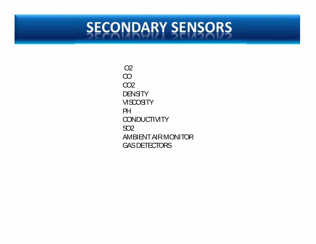
O2 CO CO2 DENSITY VISCOSITY PH CONDUCTIVITY SO2 AMBIENT AIR MONITOR GAS DETECTORS
Various instruments used in Process Industries

PRESSURE GAUGE


Primary sensor - Capacitor


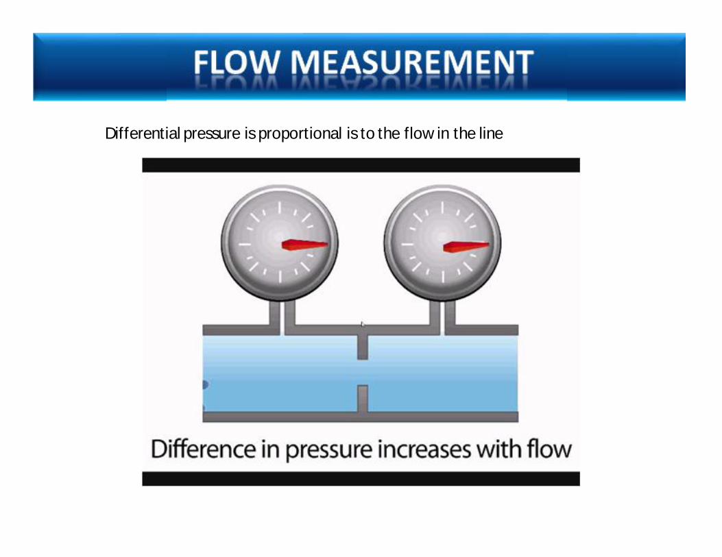
Differential pressure is proportional is to the flow in the line

Bernoulli's equation states that the sum of all forms of energy in a fluid flowing along an enclosed path is the same at any two points in that path


How does Plane speed measured?

TURBINE METER


DRIVE COILS
MASS BAR
TORSION ROD
PICK-UP COILS
TUBE LOOPS
ELECTRICAL JUNCTION BOX FLANGE
CONNECTIONS

The mass flow of a u-shaped coriolis flow meter is given as:
where Ku is the temperature dependent stiffness of the tube, K a shape-dependent factor, d the width, τ the time lag, ω the vibration frequency Iu the inertia of the tube.


When there is a flow, there is some twisting of the tubes. The arm through which fluid flows away from the axis of rotation must exert a force on the fluid to increase its angular momentum, so it is lagging behind the overall vibration. The arm through which fluid is pushed back towards the axis of rotation must exert a force on the fluid to decrease the fluid's angular momentum again, hence that arm leads the overall vibration. The inlet arm and the outlet arm vibrate with the same frequency as the overall vibration, but when there is mass flow the two vibrations are out of sync, the inlet arm is behind, the outlet arm is ahead. The two vibrations are shifted in phase with respect to each other, and the degree of phase-shift is a measure for the amount of mass that is flowing through the tubes.


Magnetic meters operate under principles identified by Faraday, which state that if a moving conductor passes through a magnetic field, a voltage will be imposed on the conductor that is proportional to the speed of the moving conductor.
The voltages generated by magnetic meters are very small, so extra care must be taken to ensure good ground connections and adequate shielding of the wires that are connected to the electrodes.

Faraday's Law : " It states that a voltage will be induced in a conductor moving through a magnetic field." E=kBDV Where E = Induced Voltage, B = Strength of the Magnetic Field, D = Conductor Width, V = Velocity of the Conductor.

The measurement of flow is based on the principle that sound waves traveling in the direction of flow of the fluid require less time than when traveling in the opposite direction. The difference in transit times of the ultrasonic signals is an indication for the flow rate of the fluid.
Since ultrasonic signals can also penetrate solid materials, the transducers can be mounted onto the outside of the pipe.

Ultrasonic flow meters measure the difference of the transit time of ultrasonic pulses propagating in and against flow direction. This time difference is a measure for the average velocity of the fluid along the path of the ultrasonic beam. By using the absolute transit times both the averaged fluid velocity and the speed of sound can be calculated. Using the two transit times tup and tdown and the distance between receiving and transmitting transducers L and the inclination angle α one can write the equations:
and
where v is the average velocity of the fluid along the sound path and c is the speed of sound. Ultrasonic flow meters are also used for the measurement of natural gas flow. One can also calculate the expected speed of sound for a given sample of gas; this can be compared to the speed of sound empirically measured by an ultrasonic flow meter and for the purposes of monitoring the quality of the flow meter's measurements.

Vortex meters make use of a natural phenomenon that occurs when a liquid flows around a bluff object. Eddies or vortices are shed alternately downstream of the object. The frequency of the vortex shedding is directly proportional to the velocity of the liquid flowing through the meter.

The three major components of the flowmeter are a bluff body strut-mounted across the flowmeter bore, a sensor to detect the presence of the vortex and to generate an electrical impulse, and a signal amplification and conditioning transmitter whose output is proportional to the flow rate. The meter is equally suitable for flow rate or flow totalization measurements. Use for slurries or high viscosity liquids is not recommended.

Filled system

Bimetallic

INVAR
Thermal expansion coefficient
3.6


Outer circle has larger area

230 V AC
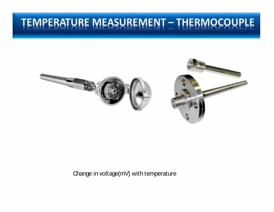
Change in voltage(mV) with temperature


Change in resistance with temperature

R=R0(1+a1T+a2T2+. . . . . …anTn) R0 is the resistance at temperature T=0

OPTICAL PYROMETER
Compares the source brightness with a standard filament

LEVEL GAUGE


Closed tanks

FLOAT

Ultrasonic 20KHz to 50KHz Radar 3 MHz to 10.5 GHz


10 meters
Speed = 1 meter / second
Time taken = 20 seconds
Level = 10 M – ( 10 seconds * 1 meters/second)
Level = 0 M
Time taken for oneway = 10 seconds

Speed = 1 meter / second
Time taken = 10 seconds
Level = 10 M – ( 5 seconds * 1 meters/second)
Level = 5M
Time taken for oneway = 5 seconds
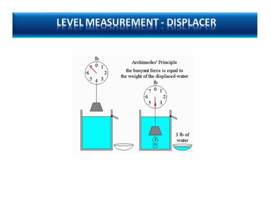

DISPLACER TYPE


RADIO ACTIVE
Radioactive source (cobalt-60) is used for this purpose to give out gamma rays. The rays penetrate the vessel and strike a GM tube kept diametrically opposite, on the other side of the vessel. The rays are obstructed when the level rises.

Rod source – point detector • Optimized distribution of the source
activity


Limit Switch Proximity Switch

Push buttons Selector Switches


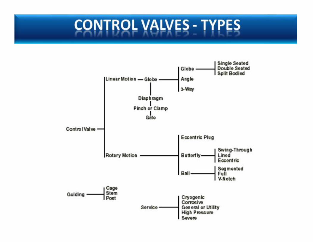
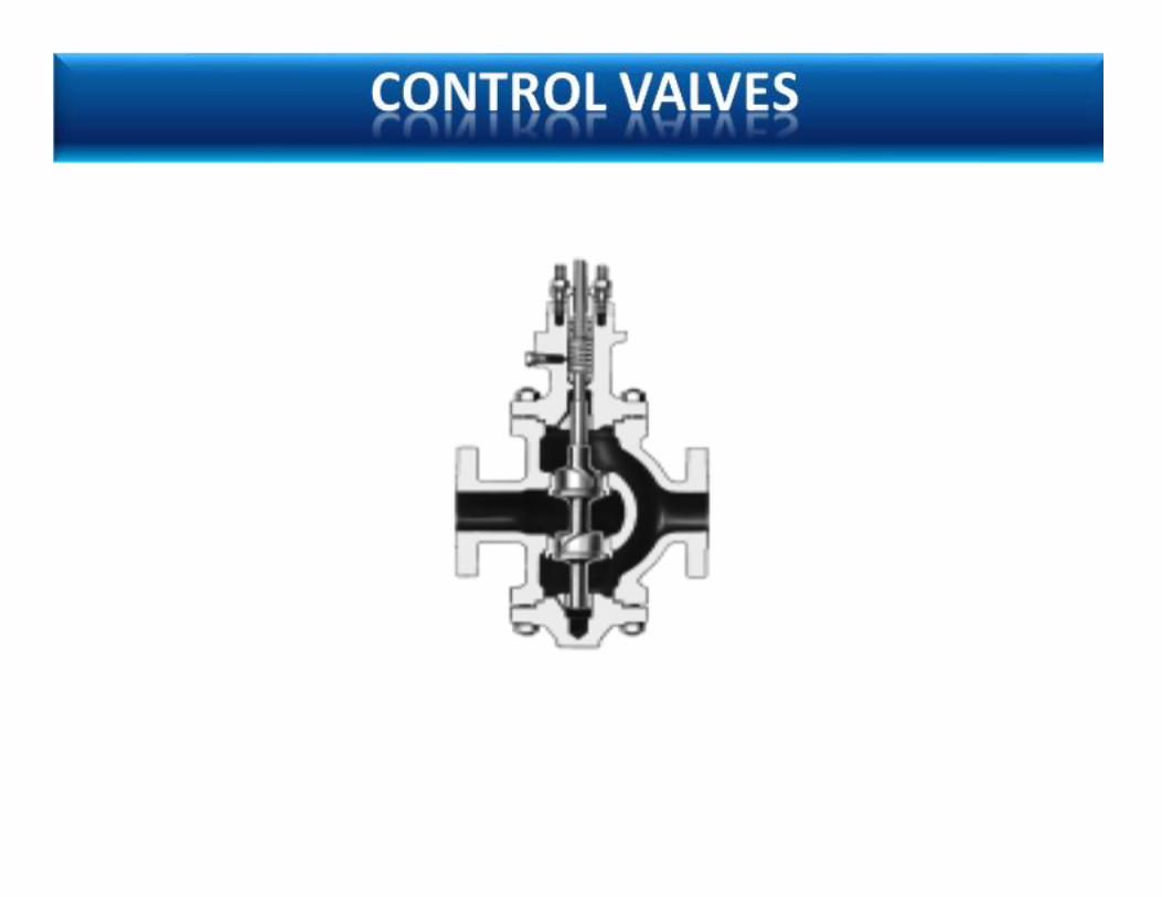
Control valves are valves used within industrial plants to control operating conditions such as temperature, pressure, flow, and liquid level by fully or partially opening or closing in response to signals received.


Instrument Air Supply
4-20 mA current Signal

Servo Electric Hydraulic Pneumatic Electric


Force = Pressure X Area Force acting on the plug 10 Kg/cm2 X Π 5cm2 780 Kg Force acting from the Diaphram .5Kg/cm2 X Π 25 cm2 980 Kg

Butterfly valve
Globe valve
Ball valve

