field standard operating procedures for the epa through
TRANSCRIPT

NPAP Field SOP Sections 0 – 11
Date: 4/7/11
1
Field Standard Operating Procedures for the EPA Through-the-
Probe National Performance Audit Program
Introduction
Name: Printed Signature Date
Contents
Section Page
Introduction .................................................................................................................................................. iii Criteria Pollutant Gases ...................................................................................................................... iii The National Performance Audit Program ......................................................................................... iii Purpose of this Document .................................................................................................................. vi Prerequisites ..................................................................................................................................... viii Definitions ........................................................................................................................................ viii
Figures Page
Figure 1. Definition of independent assessment. .......................................................................................... v
Table Page
Table 1. Required Reading for the National Performance Audit Program ................................................ viii

NPAP Field SOP Sections 0 – 11
Date: 4/7/11
[This page intentionally left blank.]

NPAP Field SOP Sections 0 – 11
Date: 4/7/11
Introduction The purpose of this section is to provide the Environmental Services Assistance Team (ESAT) Field Scientists (FSs) with background information on the EPA’s Through-The-Probe (TTP) method of delivering single-blind audit samples of EPA Criteria Pollutant gases under the National Performance Audit Program (NPAP) as an introduction to standard operating procedures (SOPs) for field personnel involved in the NPAP.
Criteria Pollutant Gases Program In general, the measurement goal of the Ambient Air Quality Monitoring Program is to estimate the concentration, in parts per million (ppm), of EPA Criteria Pollutant gases (SO2, NO2, O3, and CO). The NPAP’s goal is to provide audit materials and devices that will enable the EPA to assess the proficiency of monitoring organizations that are operating monitors in the SLAMS/PSD network. One major objective for the collection of the audit data is to assess gas analyzer bias near the concentrations in the National Ambient Air Quality Standard (NAAQS) as required by 40 CFR Part 58, Appendix A.
The National Performance Audit Program Because data from State and Local Ambient Monitoring Stations (SLAMS) and Prevention of Significant Deterioration (PSD) multi-pollutant monitoring stations are used for NAAQS comparisons, the quality of these data is very important. A quality system has been developed to control and evaluate the data quality to assure that NAAQS determinations are within an acceptable level of confidence. During the development of the NAAQS, the U.S. Environmental Protection Agency (EPA) used the Data Quality Objective (DQO) process to determine the allowable measurement system imprecision and bias that would not significantly affect a decision maker’s ability to compare pollutant concentrations to the NAAQS. The NPAP is a quality assurance (QA) activity that will be used to evaluate measurement system bias of the gaseous criteria pollutant monitoring network. The pertinent regulations are found in 40 CFR Part 58, Appendix A, Section 3.2.2. The strategy is to supply the SLAMS/PSD instrument with an audit gas generated on-site at concentration ranges specified in 40 CFR Part 58, Appendix A, Section 3.2.2.1.
Initially, the NPAP was implemented by mailing standards and gases to monitoring organizations for analysis. In 2003, OAQPS instituted a through-the-probe audit system where audit laboratories travel to monitoring sites and generate audit gases for immediate delivery through the inlet probe of the analyzers. The goals of the NPAP are:
Performing audits at 20 percent of monitoring sites per year, and 100 percent in 5 to 7 years.
Data submission to AQS.
Development of a delivery system that will allow for the audit concentration gases to be introduced into the probe inlet where logistically feasible
Use of audit gases that are NIST certified and validated at least once a year for SO2, NO2, and CO.

NPAP Field SOP Sections 0 – 11
Date: 4/7/11
Validation/certification with the EPA NPAP through collocation auditing at an acceptable number of sites each year. The comparison tests would have to be no greater than 5 percent different from the EPA NPAP results.
Incorporation of NPAP in the monitoring organization’s quality assurance project plan (if self implementing).
In general terms, a performance audit consists of presenting audit gas mixtures containing known concentrations to the measurement system to evaluate the proficiency of the analyst or laboratory. The difference between the known concentrations and the system responses is obtained, and an estimate of accuracy is determined. In the case of the NPAP, the goal is to assess the proficiency of monitoring organizations that are operating monitors in the SLAMS/PSD networks.
The implementation of a program of independent and adequate audits is a State, local and Tribal (SLT) responsibility; however, a QAPP which provides for monitoring organization participation in the NPAP meets this requirement. Monitoring organizations may self-implement the NPAP with demonstrated independence of the audit gas generating personnel and the monitoring system operator. Independent assessment (Figure 1) was defined by the PM2.5 QA Workgroup to ensure that the appropriate level of independence is maintained during SLT implementation of the PEP. This definition has been adopted by the NPAP for consistency within the programs.

NPAP Field SOP Sections 0 – 11
Date: 4/7/11
Independent assessment—an assessment performed by a qualified individual, group, or organization that is not part of the organization that is directly performing and
accountable for the work being assessed. This auditing organization must not be involved with generating the routine ambient air monitoring data. An independent
organization could be another unit of the same agency, which is sufficiently separated in terms of organizational reporting and can provide through-the-probe audit gases.
An organization can conduct the NPAP if it can meet the above definition and has a management structure that, at a minimum, allows for the separation of its routine monitoring personnel from its auditing personnel by two levels of management as
illustrated in the figure below. Audit gas generation personnel would be required to meet the NPAP training and certification requirements.
Organizations planning to implement the NPAP must submit a plan that demonstrates independence to the EPA Regional Office responsible for overseeing QA-related
activities for the ambient air monitoring network.
Figure 1. Definition of independent assessment.
Organization 3rd Level
Supervision
Organization 2nd Level
Supervision
Organization 2nd Level
Supervision
Organization 1st Level
Supervision
Organization 1st Level
Supervision
Organization Personnel
Audit Gas Generation
Organization Personnel
Routine Monitoring

NPAP Field SOP Sections 0 – 11
Date: 4/7/11
In 2003, when EPA moved to through-the-probe delivery of audit gases, the agency investigated potential contracting mechanisms to help implement this activity. Based on the success of the Environmental Services Assistance Team (ESAT) contracts currently in place in each EPA Region in providing the necessary field and laboratory activities for the FRM/FEM PEP, additional tasks covering the TTP activities were added to the contracts. Although all EPA Regions implement the NPAP, resources, including audit laboratories and analyzers, are shared between Regions to reduce capital costs.
Field Activities
The NPAP audit laboratories are designed to verify and deliver audit gases through the probe inlet of ambient air monitoring stations. The laboratories, gas generation system, and analyzers have been selected and approved by EPA and are designed to be durable, rugged, and capable of frequent transport. Although the systems have been specifically designed to perform these audits, precautions must be taken to ensure the quality of the data. Specific and detailed instructions can be found in the Quality Assurance Project Plan (QAPP) for the Audit Support Program and throughout these SOPs. A brief summary of the field activities follows:
One fully trained FS will drive the audit laboratory to the monitoring station, which shall be located at any of the SLAMS/PDS stations within each EPA Region.
The FS will verify the operation of the audit gas generation system.
The FS will coordinate the delivery of the audit gas through the station inlet probe, verify the concentration delivered, and obtain the station reading from the station operator.
A Draft Audit Report will be provided to the station operator, or the monitoring organization’s representative, prior to departure from the monitoring station.
The Draft Audit Report will be provided to the ESAT Work Assignment Manager/Task Order Project Officer/Delivery Order Project Officer/Task Order Manager (WAM/TOPO/DOPO/TOM) and Regional QA Office for final review and ultimate delivery to the monitoring organization.
The FS will properly maintain and operate the audit laboratory following manufacturer recommended procedures for gas analyzers, zero-air generators, on-board electric generators, vehicles, and other equipment as described in these SOPs.
Purpose of this Document
The purpose of the NPAP TTP SOPs is to provide detailed procedures to follow when performing the following activities:
Overview
Planning/preparation
Calibration Checks (Verifications) and Procedures
Audit Laboratory Start-up Procedures
Site Set-up
Through-the-Probe (TTP) Performance Audit (PE)
Post Performance Audit Procedures

NPAP Field SOP Sections 0 – 11
Date: 4/7/11
Shut-down Procedures
Maintenance Checks and Procedures
Quality Assurance/Quality Control
Information Retention
All procedures are to be followed completely. Any deviation must be reported in writing and submitted to the ESAT Work Assignment Manager/Task Order Project Officer/Delivery Order Project Officer/Task Order Manager (WAM/TOPO/DOPO/TOM).
NOTE: If any deviation or modification offers a more efficient method or technique or serves to maintain or improve data quality, these proposed changes shall be made in writing to the ESAT WAM/TOPO/DOPO.
Each SOP section is written as a stand-alone procedure to assist in training and certification activities and can be removed from the document and made readily available at the station where the activity takes place. The SOP sections are labeled for reference as NPAP TTP-X, where NPAP TTP indicates the NPAP Through-the-Probe SOPs and X indicates the section number. The SOPs follow the format for technical SOPs outlined in EPA’s Guidance for the Preparation of Standard Operating Procedures (SOPs) EPA QA/G-6. The QA/G-6 requirements include the following topics:
A. Scope and Applicability
B. Summary of Method
C. Definitions (acronyms, abbreviations, and specialized forms used in the SOPs)
D. Health and Safety Warnings
E. Cautions
F. Interferences
G. Personnel Qualifications
H. Apparatus and Materials
I. Instrument or Method Calibration
J. Sample Collection
K. Handling and Preservation
L. Sample Preparation and Analysis
M. Troubleshooting
N. Data Acquisition, Calculations, and Data Reduction
O. Computer Hardware and Software
P. Data Management and Records Management.

NPAP Field SOP Sections 0 – 11
Date: 4/7/11
Prerequisites
Training and Certification
All field scientists funded by the OAQPS NPAP Work Assignment must be trained and certified to perform the activities. Training and recommendation for certification can be provided by the Regional WAM/TOPO/DOPO or by OAQPS.
Background Reading
Prior to implementing field activities, field personnel are expected to be familiar with the documents listed in Table 1. The knowledge level is rated from 1, having in-depth knowledge, to 5, having a basic understanding.
Table 1. Required Reading for the National Performance Audit Program
Document Knowledge Level
NPAP TTP SOPs 1
Quality Assurance Project Plan (QAPP) for the Audit Support Program 1
Operating Manuals for analyzers and instrumentation in audit laboratory 1
QA Guidance Document 2.12* 3
NAAQS Criteria Pollutant gases DQO Process 3
QA Handbook Vol. II Part 1 3
40 CFR Part 50, Appendices A, C, D and F 4
40 CFR Part 58, Appendix A 4 * The 2006 revisions to monitoring regulations supersede specific requirements of QA Guidance Document 2.12.
Definitions
Appendix A contains a glossary of the terms used in the NPAP. Acronyms and abbreviations can be found in the front of this compendium.

NPAP Field SOP Sections 0 – 11
Date: 4/7/11
[This page intentionally left blank.]

NPAP Field SOP Sections 0 – 11
Date: 4/7/11
Field Standard Operating Procedures for the EPA Through The Probe National Performance Audit Program
Section 1
Overview of Performance Evaluation Field Activities
SOP: NPAP-1
Name: Printed Signature Date
Contents Section Page
1.1 Overview of NPAP TTP Field Activities ……………………….………………………… 1-3
1.1.1 Scope and Applicability …………………………………………………………... 1-3 1.1.2 Summary of Method ……………………………………………………………… 1-3 1.1.3 Definitions ………………………………………………………………………... 1-3 1.1.4 Health and Safety Warnings………………………………………………………. 1-3 1.1.5 Cautions …………………………………………………………………………... 1-4 1.1.6 Interferences ……………………………………………………………………… 1-5 1.1.7 Personnel Qualifications ………………………………………………………….. 1-5 1.1.8 Equipment and Supplies ………………………………………………………….. 1-6 1.1.9 Procedures ………………………………………………………………………… 1-7
1.1.10 References ……………………………………………............................................ 1-9
Figures Page
1.1 NPAP TTP Audit Lab Plumbing Schematic…………….…………….……………… .......... 1-6 1.2 NPAP TTP PE SOP Tasks……………………………………………………… ................... 1-8

NPAP Field SOP Sections 0 – 11
Date: 4/7/11
[This page intentionally left blank.]

NPAP Field SOP Sections 0 – 11
Date: 4/7/11
1.1 Overview of NPAP TTP Field Activities 1.1.1 Scope and Applicability This SOP applies to performing NPAP TTP field operations and provides an overview of the detailed SOPs that follow. Regulations related to these procedures are found in 40 CFR Part 58 Appendix A Section 2.4. 1.1.2 Summary of Method A PE is used for determining total bias for National Ambient Air Quality Standard (NAAQS) Criteria Pollutant gases. The performance evaluation gas samples are dynamically generated and independently verified by EPA funded personnel onsite. The test gas samples are delivered to and through the entire ambient air monitoring sampling system of the organization being evaluated, starting with entry into the monitoring station’s sampling inlet, or “probe”. The concentrations measured by the station instruments and NPAP audit lab are then compared to assess bias. NPAP TTP PEs will be conducted as follows: Primary QA organizations are required to complete audits of 20% of stations each year. 100% completeness (whatever it takes to report valid audits for 20% of stations each year)
All stations subject to an audit within 5 years.
Special priority will be given to those stations documented or expected to have concentrations near the annual NAAQS for Criteria Pollutant gases (40 CFR Part 58, Appendix D). The basic operations involved with conducting the field portion of the PE are described in the SOP sections contained in this document. 1.1.3 Definitions Appendix A contains a glossary of terms used in the NPAP TTP. 1.1.4 Health and Safety Warnings To prevent personal injury, all personnel must heed any warnings associated with the transport and operation of the NPAP audit trailer and any supporting equipment and supplies. Specific health and safety warnings will generally be found at the point in the operating manual or troubleshooting guide where they are most applicable. The following issues are of particular concern: Adhere to all warnings associated with operation of the TTP tow vehicle, hitch, and trailer.
Assure the readiness of hitch brake emergency disconnects prior to moving the vehicle and trailer.

NPAP Field SOP Sections 0 – 11
Date: 4/7/11
State and local law governs the placarding of vehicles carrying compressed gases. Field scientists must be aware of the location of cylinder hazard placards and the requirements for use in all jurisdictions included in the audit trailer schedule.
1.1.5 Cautions Because the mobile audit lab and components will be moved from site to site, it is of critical
importance that it be maintained and calibrated as required and that all aspects of its operation be checked and verified after it is set up at each site. To function as a reliable standard of comparison, its operational parameters must be kept within tight control limits.
Caution must be taken to install and maintain the TTP system components properly to prevent
damage. Be particularly attentive to maintenance of the auxiliary generators, air conditioners, API 701, Environics 9100, analyzers (CO and ozone) and computer. Ensure the soundness of electrical and pneumatic connections that will be assembled and disassembled and to cleaning the interior and exterior surfaces of the manifolds, connecting tubing, and delivery hose lines. Establish and always use individual instrument logs for recording purpose; keep the logs with the instruments at all times. All necessary corrective actions must be taken before PE can begin with the TTP system.
Equipment that must be checked prior to and during each trip to ensure that it is operating
correctly: tow vehicle and trailer tires for air, auxiliary generators for oil leaks, roof A/C units for Freon (or EPA -approved-substitute), generator fuel tank leaks (use dip stick), brake fluid leaks(remove rubber seal cap on each wheel hub center); roof platform guard rail lockdown mechanism; interior cabinet and drawer latches, storage tie downs, cylinder rack tie downs, cylinder fitting tightness, presence and use of regular and yellow clamshell safety cylinder caps; emergency and all other lights; exterior trailer door, port, and fuel tank locks; inflation pressure of each of the instrument rack pneumatic, floor-mounted shock absorbers; test switch for battery indicator of CO monitor/alarm; status of fire extinguisher and safety kit; status of exterior trailer tongue and loading jacks.
The TTP system components used for PE are potentially vulnerable to contamination and
damaged. Exercise care in handling new components. Avoid touching the flow path component interior surfaces; normally handle the components only by touching the exterior surfaces. If details concerning component labeling and connection are not followed precisely, errors will result. Rough handling of used components during packaging or transport should be avoided.
Protect the cylinder pressure gauges any from mechanical shock and sudden changes in
pressure. It is possible to damage station instrumentation if it is pressurized during the audit gas delivery.
Always examine the station inlet, determine necessary gas delivery rates to obtain a valid audit while protecting the station. Review instrument pressure before and during the audit to verify appropriate flows. Communication with the station operator regarding these issues is critical to a successful audit.

NPAP Field SOP Sections 0 – 11
Date: 4/7/11
1.1.6 Interferences The interferences associated with this method are factors that can cause alterations to concentration of the audit gases. Such changes in concentration can be the result of loss (through leak or reactivity) or contamination. Interferences can be minimized by following these guidelines: Take precautions to prevent the introduction of dirt or debris into the gas flow path. Visually
examine the path, including the manifold, regularly to detect any material that has been introduced – clean as appropriate prior to attempting an audit. Do not jeopardize the integrity of the flow path by opening connections unnecessarily or leaving fittings open and uncapped.
Take all steps to minimize sampling and analysis residence times, including tubing and other flow
path component lengths and diameters, dead spaces, leaks, unnecessary path resistance (due to sharp bends, kinks, etc.).
To avoid any contamination of the flow path and analytical devices; ensure that the PE
test gas flow path’s interior surfaces are clean, including manifolds, tubing, fittings, delivery /presentation hose pipe connections and liner. Use required leak checks to identify and correct any leaks found within the flow system.
Follow procedures for purging the cylinder pressure gauges to remove interference
caused by either bleeding from the regulators or reaction of the gases in the gauges and lines.
Water vapor can result in false positive analyzer readings and inaccurate dynamic
dilution concentrations. To minimize this interference, use only well-dried zero air. 1.1.7 Personnel Qualifications All personnel responsible for conducting EPA TTP PEs at field sites must be certified once per year by the U.S. EPA as completing required training to be eligible to conduct TTP PEs. All operators (those new to the program as well as experienced TTP Audit Lab operators) must be certified as attending a training program. During the training program, operators of the TTP Audit Lab must successfully complete an extensive, hands-on training session specified by EPA/OAQPS and pass both written and performance tests. A new operator must complete three (3) audits supervised by an experience operator approved by the regional TOPO/WAM before he or she is eligible to conduct TTP PEs. The training programs will be conducted as required at locations throughout the U.S. to ensure all FS are trained and an adequate number of PE FSs are available in each EPA Region. Contact the Regional EPA Office or OAQPS for more information about training schedules and locations. Supplemental courses such as those offered by Air Pollution Training Institute (APTI) may be useful in providing general background to personnel with limited experience with air monitoring and/or quality assurance. The TTP Audit Labs are either truck or trailer-mounted (see subsection 7 for detailed description). The FS shall be prepared to drive the TTP Audit Lab from the home base to various ambient air monitoring stations which may be difficult to access or located in distant rural settings. The TTP Audit Lab should be legally parked within 150 feet of the air monitoring station inlet (probe), which is frequently located

NPAP Field SOP Sections 0 – 11
Date: 4/7/11
atop a building or platform. The FS will have to maneuver the lab in forward and reverse gears, and on various roads at speeds up to the posted limit without damaging the TTP system. EPA has begun providing a training program for towing boat trailers, which has been modified, to some extent, for towing mobile labs and may be appropriate for FS assigned trailer-mounted labs.
1.1.8 Equipment and Supplies Each organization responsible for performing the TTP PE has a TTP Audit Lab made available by OAQPS. The truck- or trailer-mounted labs are designed to be self-contained with onboard generators, UPS, and other features designed to ensure a stable and safe environment for the FS and audit equipment. A plumbing schematic of the components in the TTP Audit Lab used to generate, verify, and deliver the audit gas is provided in Figure 1-1. Each organization responsible for performing the TTP PE will develop a standard "kit" of equipment, materials, and supplies suitable for the make(s) and model(s) of TTP Audit Lab components to be used. The contents of this "kit" will also be determined by the different requirements of the sites to be visited for TTP PEs. A critical component of the “kit” is a variety of fittings and tubing (made of non-reactive materials) for use in connecting the delivery hose to the station inlet (probe). SOP NPAP TTP-2.01 contains a complete field inventory list and discusses the procedures for field equipment and supply. That list of generic equipment and supplies must be translated into a specific checklist of equipment and materials that can be customized as necessary. Communications between the FS and site personnel prior to the visit are essential and assist greatly in knowing what will be required at each site.
1/4 inch teflon
vent
Three way valve By-passneedle valve Rotameter
stainless tubingmixing train SS Tee
manual solenoid valvesRotameter
optional pressure sensortank valves needle valve wired to DAS& regulators
needle valveTo hose reel (3/8 inch teflon)
1/8 inch stainless
Ultrapure zero air
zero High CO
Multi-
blend
Environics 9100
Zero Air Generator
rear manifold
front manifold
Ozone Standard
NO2 Analyzer
CO Analyzer
Low CO
Figure 1-1. TTP Audit Lab Plumbing Schematic

NPAP Field SOP Sections 0 – 11
Date: 4/7/11
1.1.9 Procedure The FS will perform the following activities as illustrated in Figure 1-2: The FS will receive equipment and consumables, inventory each item and ensure supplies are
adequate to perform field activities. The FS will maintain the TTP Audit Lab standards and equipment as required:
o Ozone standard devices will be compared to a NIST-manufactured SRP quarterly. o The compressed gas standards will be certified against independent NIST-traceable
compressed gas standards annually. The multi-blend cylinder and CO calibration gas cylinders pressure should remain above 325 PSI to allow for recertification at the completion of an audit trip to verify stability.
o The ozone line loss factor of the TTP PE delivery hose will be verified quarterly. The FS will assist in developing a plan for the implementation of field activities and gather
pertinent information for each site on a Site Data Sheet. Communication regarding the location of the station inlet, required connecting equipment for the delivery hose, and other logistics should be completed prior to departing on an audit trip.
The FS will drive the EPA TTP Audit Lab from the home base (or intermediate scheduled PEP
sites) to the scheduled PE site. The FS will complete warm-up and pre-arrival conditioning and stabilization procedures to minimize time needed at the PE site.
Upon arrival at the scheduled PE site, the FS will park the TTP Audit Lab in a legal
location. The lab must be located to facilitate connection of the delivery hose to the station inlet. The FS will obtain all necessary information for the TTP spreadsheet from the station operator. After communicating with the station operator to determine required flow and to assure that the station analyzers are off-line, the FS will connect the delivery hose to the station inlet.
The FS will calibrate the onboard CO analyzer to make sure that they are operating correctly, in
comparison to pre-PE trip performance tests. The FS will then make and record the results of the zero and upscale settings that should result in the flows and concentrations that his/her calculation has indicated. The FS will check that the PE gas being generated by the TTP Audit Lab is within acceptable limits using the ozone and/or CO analyzers. The EMC data strip charting and PC-based recording and HP printout are used to track, record, and document the stabilization profile of the process.
Once the FS has verified that the TTP Audit Lab values are correct and stable, the FS asks the
station operator to provide the station values, following any and all procedures they normally follow to get their own field monitoring results. The station and TTP Audit Lab results are recorded by the FS on the ozone and/or blended gas PE result forms.
The FS provides the station operator with a Preliminary PE Data Form, and conducts
shutdown tasks according to the TTP SOP and associated checklists. If scheduling and resources allow, the FS may complete other assignments during the TTP
stabilizing steps. For example, the FS may:

NPAP Field SOP Sections 0 – 11
Date: 4/7/11
o leave this TTP site to set up a PEP sample at another sampling locations. o perform any required maintenance or repair of the mobile TTP lab components. o return to a PEP site after the 24-hour PEP sampling period, remove and properly store the
PEP filter for transport, download the stored electronic monitoring data, enter additional information as required, and disassemble and pack the sampler.
The FS, if a contractor, shall participate in or assist with scheduled quality assurance activities of
the NPAP TTP, if and as required by contract Task Order and TDF.
Ozone line loss, standards certification, total system checks TTP-3
,
Equipment inventory, communications,site visit peparation TTP-2
NPAP audit lab transport TTP-4Site set-up TTP-5Pre/post calibrations, audit evaluations, preliminary report TTP-6, TTP-7
Information retention
TTP-11
Maintenance TTP-9
System Shutdown TTP-8
Figure 1-2. NPAP TTP PE SOP Tasks

NPAP Field SOP Sections 0 – 11
Date: 4/7/11
1.1.10 References
1. 40 CFR Parts 50 and 58.
2. Quality Assurance Handbook for Air Pollution Measurement Systems, Volume II Ambient Air Quality Monitoring Program, EPA-454/B-08-003, December, 2008.
3. Thermo Environmental Instruments, Inc. Instruction Manual for Model 48C.
4. Thermo Environmental Instruments, Inc. Instruction Manual for Model 49C-PS.
5. Environics Series 9100 Operating Manual.
6. Advanced Pollution Instrumentation, Inc. Instruction Manual for Model 701.
7. Powerware 9125, User’s Guide.
8. ONAN Commercial Mobile Power, Operator’s Manual (Models HGJAD, HGJAE, HGJAF).
9. Duo-Therm 579, Series BRISK AIR.
10. WELLS CARGO Owner’s Manual .
11. DEXTER AXLE, Operation Maintenance Service Manual.
12. Atwood Battery Operated Carbon Monoxide Alarm User’s Guide.

NPAP Field SOP Sections 0 – 11
Date: 4/7/11
[This page intentionally left blank.]

NPAP Field SOP Sections 0 – 11
Date: 4/7/11
Field Standard Operating Procedures for the EPA Through The
Probe National Performance Audit Program
Section 2 Planning and Preparing for NPAP Site Visit
SOP: NPAP-2
Name: Printed Signature Date
Contents
Section Page
2.1 Equipment Inventory and Storage ........................................................................................ xxii 2.1.1 Scope and Applicability ................................................................................................. xxiii 2.1.2 Definitions ..................................................................................................................... xxiii 2.1.3 Personnel Qualifications ................................................................................................ xxiii 2.1.4 Equipment and Supplies ................................................................................................ xxiii 2.1.5 Procedure ....................................................................................................................... xxiii 2.2 Communications .................................................................................................................. xxxv 2.2.1 Scope and Applicability ................................................................................................ xxxv 2.2.2 Summary of Method ..................................................................................................... xxxv 2.2.3 Definitions .................................................................................................................... xxxv 2.2.4 Equipment and Supplies ............................................................................................... xxxv 2.2.5 Phone and E-mail Communications ............................................................................. xxxvi 2.2.6 Monthly Progress Reports ......................................................................................... xxxviii 2.2.7 Records Management ................................................................................................ xxxviii 2.3 Preparation for NPAP Site Visits ......................................................................................... xlvii 2.3.1 Scope and Applicability ................................................................................................. xlvii 2.3.2 Summary of Method ...................................................................................................... xlvii 2.3.3 Definitions ..................................................................................................................... xlvii 2.3.4 Personnel Qualifications ................................................................................................ xlvii
NPAP Field SOP Sections 0 – 11
Date: 4/7/11
2.3.5 Cautions ......................................................................................................................... xlvii 2.3.6 Equipment and Supplies ................................................................................................ xlvii 2.3.7 Procedure ...................................................................................................................... xlviii 2.3.8 References ........................................................................................................................... li
Tables Page
Table 2-1. Equipment and Supplies ........................................................................................................ xxiv Table 2-2 ESAT Contacts .................................................................................................................... xxxviii
Figures Page
Figure 2-1. Line of communication. ....................................................................................................... xxxv
Forms Page
Field Inventory Form ............................................................................................................................... xxxi Field Equipment/Consumable Receiving Report .................................................................................... xxxii Procurement Log .................................................................................................................................... xxxiii FORM COM-1 .......................................................................................................................................... xliv Phone Communication Form .................................................................................................................... xliv FORM COM-2 .......................................................................................................................................... xlvi Monthly Progress Report .......................................................................................................................... xlvi FORM SD-01 ............................................................................................................................................... lv

NPAP Field SOP Sections 0 – 11
Date: 4/7/11
[This page intentionally left blank.]

NPAP Field SOP Sections 0 – 11
Date: 4/7/11
2.1 Equipment Inventory and Storage 2.1.1 Scope and Applicability
This SOP explains the activities involved in inventorying existing laboratory equipment, receiving new equipment and consumables, and maintaining the equipment.
2.1.2 Definitions
Appendix A contains a glossary of the terms that used in the NPAP TTP.
2.1.3 Personnel Qualifications
All personnel responsible for conducting EPA TTP PEs at field sites must be certified once per year by the U.S. EPA as completing required training to be eligible to conduct TTP PEs. All operators (those new to the program as well as experienced TTP Audit Lab operators) must be certified as attending a training program. During the training program, operators of the TTP Audit Lab must successfully complete an extensive, hands-on training session specified by EPA/OAQPS and pass both written and performance tests. A new operator must complete three (3) audits supervised by an experience operator approved by the regional TOPO/WAM before he or she is eligible to conduct TTP PEs.
2.1.4 Equipment and Supplies
The FS will use the following apparatus and materials to perform the procedures in this section:
Table 2-1 providing a listing of the equipment and consumables needed for the field.
Field Inventory Form INV-01
Field Procurement Log PRO-01
Field Receiving Report Form REC-01
2.1.5 Procedure
2.1.5.1 Equipment Inventory
A list of the required capital equipment and consumables is provided in Table 2-1. The FS will follow the procedure below:
Select Field Inventory Form INV-01.
Take a complete inventory of all equipment and supplies.
Keep an original copy and file under AIRP/486. Provide a copy of the inventory to the regional TOPO/WAM.
The FS should maintain a 2-months’ supply of consumables. During the first weeks of implementation, the FS will determine how quickly he/she is using consumable equipment and develop a purchasing schedule to ensure an adequate supply is maintained.
Table 2-1 must be translated into a specific checklist of equipment and materials that can be customized as necessary. Communications between the FS and site personnel prior to the visit are essential and assist greatly in knowing what will be required at each site.

NPAP Field SOP Sections 0 – 11
Date: 4/7/11
Table 2-1. Equipment and Supplies Qty. NPAP Field Equipment and Supplies Vendor/Catalog # Make/Model #
Monitoring Equipment and Supplies Item Number: 15655WT Spare wheel and tire for mobile
audit trailer
Transport cases for loose equipment/consumables Forestry Suppliers/31113
Collapsible crate
1 Cylinder Hand-Transport Carts Fisher Scientific 23-1200 air products
Operations manual(s) Field notebook(s) Clipboard (8 x 14") Forestry Suppliers
/53283 Cruiser mate
Grip Binders Office Depot/501-627 Presstex NPAP TTP Field SOPs (this document)
Documentation forms or data sheets, preprinted 1 Computer with audit workbook/spreadsheet and printer 1 Data logging system EMC Station Manager Data Logger/PC Platform
Magnetic compass or other means of determining site orientation (optional)
Forestry Suppliers/ 37177
Suunto Partner II
Tape Measure (metric) Forestry Suppliers/ 39651
Lufkin/ W 9210ME
Cellular phone Mechanical Pencils
Markers (indelible) Skilcraft
Sharpees 9mm
Ultrafine
Connecting(Mounting)Equipment/Manifold System (See Calibration/Verification Standards and Related Equipment)
FEP Teflon Tubing - 1/4" O.D. - 1/8 I.D. - 1/16" Wall thickness Cole-Parmer Instr Co 1-800-323-4340
16 FEP Teflon 1/4" plug Georgia Valve and Fitting
Swagelok Part No. NY-400-P
16 FEP Teflon reducing unions, 5/16:x1/4" Georgia Valve and Fitting
Swagelok Part No. NY-500-6-4
1 FEP Teflon reducing unions, ½" x 3/8" Georgia Valve and Fitting
Swagelok Part No. NY-810-06-06
1 FEP Teflon reducing unions, ½"x1/4" Georgia Valve and Fitting
Swagelok Part No. NY-810-6
1 FEP Teflon 3/8" plug Georgia Valve and Fitting
Swagelok Part No. NY-600-P
4 Part No.3190T6 - vibration and noise control strut mount clamp for 3/4" tube OD
MCMASTER-CARR SUPPLY CO
2 13/16" single channel strut, 24" long MCMASTER-CARR SUPPLY CO
Part No.3310T612
4 strut channel end cap, frame style, for 13/16"single channel (15/8" x 13/16")
MCMASTER-CARR SUPPLY CO
Part No. 3312T41
1 Glass (Annealed Borosilicate) Inlet Connector T’s- Research & Dev. Glass Product & Equipment
1 Needle Valve
Cross Instruments Model 4Z-V4LN-SS, (sharp stem)
1 ½" by 100’ stainless steel-braided line Cross Instruments Parker-Hannifin
1 Line-loss test apparatus: stainless steel tee with 2' of Teflon line
1 Rotameter (flow meter) Dwyer Instruments Model VFA-21

NPAP Field SOP Sections 0 – 11
Date: 4/7/11
Qty. NPAP Field Equipment and Supplies Vendor/Catalog # Make/Model # 3;1 Two-way 24 VDC solenoid valve; three-way manual valve to
actuate the zero air supply and gas cylinders ( Trailer Contractor purchase)
ASCO Red Hat
1 Rack Mount Kit (4 post rack support kit for 19" racks for #9125-4 post UPS
Major Power
2 Instrument Racks (Pioneer Series) Lab Contractor Purchase) APW Masking tape GSA-7510-00-283-
0612
Packaging tape GSA-7510-00-079-7906
Strapping tape GSA-7510-00-159-4450
Tool box with basic tools Rope for hoisting equipment 16 foot - Type 1A- Articulated Ladder Flashlight with spare batteries Heavy-duty, grounded, weatherproof electrical extension cord
with multiple outlets (25 ft. length) Unicor Style3 Class2 Series2
Heavy-duty, grounded, weatherproof electrical extension cord with multiple outlets (12 ft. length)
Unicor Style3 Class2 Series2
Land line: electrical receptacles and extension cable(cord) with matching plugs (Regions 6 and 9; made in Las Vegas)
Leviton 3-wire 30 to50 amp,
125V
CS63-70
Calibration/Verification Standards and Related Equipment (See Manifold System above)
1 UPS + Power Line Conditioner Major Power POWERWARE 9125-2000 1 Audit Hose Assembly, Braided Stainless Steel(SS), Teflon Lined,
150ft long, ½" O D Parker-Hannifin P919TUTU80808C
1 S S Hose Connector Georgia Valve and Fitting
Swagelok , Part No. SS-810-1-8
1 S S Hose Connector Georgia Valve and Fitting
Swagelok, Part No. SS-810-5-6
1 Continuous Zero Air Generator API API Model 701 1 Computerized Ambient Calibrator (with ozone generator) Environics Environics 9100 1 CO Analyzer TECO TECO 48C 1 Ozone Analyzer (with Generator) TECO TECO 49C-PS 1 Combined UPS and PLC Major Power Major Power PowerWare
9125-2000
2 KW Auxiliary Gasoline Generator(Mfr: Onan) Cummins ONAN CMM 1 Ultra Pure Air Scott-Marin, Inc 1 Regulator for Blended CO, SO2 and NO National Welders/ CONCOA 442-2301-660 2 Regulators for Ambient CO National Welders CONCOA 422-2301-590 4 Clam shell covers for cylinders with regulators Griftan Inc.
PO Box 1296 Georgetown, SC 29442 www.griftaninc.com
1 Compressed gas cylinder - CO, High Ambient, approx 40 ppm, NIST Traceable EPA Protocol Gas
Scott-Marrin, Inc Size 150
1 Compressed gas cylinder - CO Low Ambient, approx. 6-8 ppm, NIST Traceable EPA Protocol Gas
Scott-Marrin, Inc
1 Compressed gas cylinder, Size 150, Blended Gas (approx. CO=10000ppm, NO=110ppm, SO2=100ppm) , NIST Traceable
EPA Protocol Gas
Scott-Marrin, Inc

NPAP Field SOP Sections 0 – 11
Date: 4/7/11
Qty. NPAP Field Equipment and Supplies Vendor/Catalog # Make/Model # 1 20 ft 316 SS tubing GA Valve & Fitting Swagelok Part No. SS-T4
S-035RL
1 Male Connector, SS, ¼” pipe to 1/8” tube GA Valve & Fitting Swagelok SS-200-2-4 3 SS Plug, ¼” O.D. GA Valve & Fitting Swagelok SS-400-P
Hand calculator (scientific) JD-22-5995 Pair of Motorola T5920 talk about FM Radios Cabela’s
1-800-237-4444
147-0860 Fuel filter for Onan generator Cummings Mid-America
1-816-414-8200
140-3116 Element air cleaner for Onan generator Cummings Mid-America
122-0836 Oil filter for Onan generator Cummings Mid-America
167-1638 Spark Plugs for Onan generator Cummings Mid-America
326-5336 Onamax 15@40 oil for Onan generator Cummings Mid-America
Air Compressor to inflate tires TOW VEHICLE
Spare Parts and Optional Equipment Spare Teflon tubing and fittings Spare Batteries (for all battery-powered equipment) Fuses, as required by all equipment used Spare in-line filters (if required by the.. Voltmeter/ammeter for troubleshooting No contaminating Dipstick for Aux. Gen.Fuel Tank
Cleaning Supplies and Equipment Low-lint laboratory wipes for cleaning TTP equipment Daigger/AX5661 Kay-Pees Disposable
paper towels
Large locking plastic bag for cleanup of debris, wipes, etc Soft brush, Supply of deionized water for cleaning and rinsing equipment Isopropyl alcohol to aid in removal of grease and dirt Penetrating oil
Lint-free pipe cleaners Lint-free cotton-tipped swabs
wooden dowel, and cloth wads to clean down tube Spray Bottle
Garbage can Place to put broom Cleaning supplies; rags to clean counter tops
Additional Equipment and other Items 1 Office chair 1 Spare tire & jack - and a place to store
Maintenance Schedule Tables; Trailer checklist

NPAP Field SOP Sections 0 – 11
Date: 4/7/11
2.1.5.2 Procurement
As consumables run low or new equipment purchases are necessary, the FS will be responsible for assisting in the procurement of these items following the policy and requirements described in the ESAT
scope of work. The FS should continue purchasing consumable equipment with the same model numbers as initially procured unless the TOPO/WAM suggests a different item due to improved quality,
reduced contamination, ease of use, or lower cost (without sacrificing quality). The following procedures will be required.
The FS will develop procurement requests as per EPA requirements.
Upon order, add items to the Field Procurement Log PRO-01.
Once a month provide a copy of Form PRO-01 to the TOPO/WAM.
File Form PRO-01 in file AIRP/486.
2.1.5.3 Equipment Consumable Receipt
Upon receiving equipment and consumables, the FS will perform the following activities:
Pull the appropriate purchase order for the incoming items from the files.
Fill out a Field Receiving Report Form REC-01 comparing the items and quantity against the purchase order and inspecting the condition of each item.
If the items received match the purchase order and the condition of the equipment or consumables is acceptable, signify this on the form and file it in AIRP/486.
If the quantity, items, or condition are not acceptable, complete REC-01 with appropriate remarks and send a copy of the form to the TOPO/WAM.
Add receipt information to the Field Procurement Log Form PRO-01
2.1.5.4 Audit Lab Storage
When equipment is not in use, store it in a clean, dry, and safe location. After completion of a field trip and return to the field office, the audit lab should be cleaned, maintained as scheduled, and stored for the next trip. All equipment should be clearly identified, and readily available for the next scheduled field trip.
2.1.5.5 Shipping Government Equipment
In the course of the NPAP it is frequently necessary to ship items around the country. Proper shipping accounts and forms assure proper billing and prevent overcharges. Always obtain the current account number before shipping. When shipping cylinders for recertification, the hazardous goods forms must be completed. When using Federal Express, do not provide a “Declared Value” on the form as this will result in insurance charges (the federal government is self-insured against loss).

NPAP Field SOP Sections 0 – 11
Date: 4/7/11
[This page intentionally left blank.]

NPAP Field SOP Sections 0 – 11
Date: 4/7/11
Section 2.1: Equipment Inventory and Storage
Field Data Forms

NPAP Field SOP Sections 0 – 11
Date: 4/7/11
[This page intentionally left blank.]

NPAP Field SOP Sections 0 – 11
Date: 4/7/11
Field Inventory Form Item Vendor Model Number Quantity Purchase Date Warranty
Form INV-01

NPAP Field SOP Sections 0 – 11
Date: 4/7/11
Field Equipment/Consumable Receiving Report Date: ___________________________
Received From:
Shipped From:
Shipped Via:
Shipping Charge:
Prepaid: Collect: Freight Bill Number:
Purchase Order Number
Quantity Description of Item Condition
Remarks: Accept Shipment _____ Problem ________
Notes:
Form REC-01

NPAP Field SOP Sections 0 – 11
Date: 4/7/11
Procurement Log
Item Model Number
Quantity PO Number
Vendor Date Cost Initials Accept/ Reject
Ordered Received
Form PRO-01

NPAP Field SOP Sections 0 – 11
Date: 4/7/11
[This page intentionally left blank.]

NPAP Field SOP Sections 0 – 11
Date: 4/7/11
2.2 Communications 2.2.1 Scope and Applicability
This procedure describes the required activities for TTP FS to communicate technical information to organizations intimately involved in the NPAP and includes:
ESAT TOPO/WAM for the FS
OAQPS
This SOP does not describe additional ESAT communication obligations described in the ESAT Scope of Work. Communications will include reports, e-mail messages and phone calls.
2.2.2 Summary of Method
An organized communications framework is needed to facilitate the flow of information among the participating organizations as well as among other users of the information produced by the ambient air monitoring network. The principal communications pathways are represented in Figure 2.2.1. In general, ESAT contractors will be responsible for informing Regions and Project Officers (POs) about technical progress, issues, and contractual obligations. On the technical side, the EPA Regional TOPO/WAMs will be responsible for communicating with Tribal, State and local agencies and informing OAQPS on issues that require technical attention. Contractual issues will be conveyed from the ESAT contractor through POs to the ESAT Contracts Office and, if necessary, to OAQPS. Table 2-2 at the end of this SOP lists the important EPA ESAT contacts.
The ESAT contractors will have frequent communication with the Regional TOPO/WAMs about the progress of their activities and any problems/issues associated with them. Resolution of these issues should take place in the Regions unless the issue could affect the implementation of the program at a national level, where it should be discussed and resolved through an ESAT Workgroup conference call.
2.2.3 Definitions
Appendix A contains a glossary of terms used in the NPAP TTP.
2.2.4 Equipment and Supplies
The following capital and consumable equipment will be required for communications:
Figure 2-1. Line of communication.

NPAP Field SOP Sections 0 – 11
Date: 4/7/11
Telephone
Laboratory PC - with Internet and EPA e-mail capabilities
Printer
Field Communication Notebook
Writing utensils
Appropriate Forms
- COM-1 - Phone Communication Form - COM-2 - Monthly Progress Report
2.2.5 Phone and E-mail Communications
2.2.5.1 Issue-Related Calls
A call may be initiated by the TOPO/WAM(s) or the FS at any time during implementation. During the conversation, the phone communication form (COM-1), in the field communications notebook, will be used by the FS to record the highlights of the conversation. Notes will include the following:
Date
Time
Personnel involved
Issue(s)
Decision(s)
Follow-up action(s)
Follow-up action responsibility
Follow-up action completed by (date)
If follow-up action is required by the FS, these actions will be included in the monthly progress reports (see Section 5.2). At a minimum, the FS will keep the original hardcopy in the field communications notebook. The FS may also choose to keep an electronic record of this information on a PC.
2.2.5.2 Field Communications
Field communications can take place either by phone or e-mail. Phone messages or conversations will be recorded in the field communications notebook. E-mail messages should be printed and stored in the field communications notebook.
NOTE: The FS must document communications; however, there is some flexibility in exactly how it can be done. The COM forms are a guide, and may be used and archived as described above or as the FS sees fit. The FS is not required to have a separate notebook just for logging communications, but it must be logged in some fashion.

NPAP Field SOP Sections 0 – 11
Date: 4/7/11
2.2.5.3 ESAT Conference Calls
The FS may be asked to participate in ESAT Workgroup conference calls to discuss progress or resolution of issues. The TOPO/WAM will inform the FS of information that needs to be prepared for the call at least 3 days prior to the call. During the call, the FS will use the Phone Communication Form (COM-1) to record issues and action items that pertain to his or her activities. These items will be included in the next monthly progress report.
2.2.5.4 Communicating with Reporting Organizations and Site Operators
Dates for the PE visits should be coordinated with the site's normal operating schedule. This coordination must be done in advance so that both the FS and the site operator have ample advance notice and time to prepare for the on-site visit. The procedure for such communications follows:
The FS will contact each site operator (by telephone) no less than 1 month prior to the site visit. Points to be covered include the following:
field implementation schedule; select a location and time to meet.
assistance in setting up the Audit Lab and delivery connection to station instruments and other assistance.
brief the operator on what will occur during the evaluation.
discuss the tasks that the site operator will be requested to do to assist with the evaluation.
additional information needed for the Site Data Sheet.
answer the site operator’s questions.
emphasize that the site’s equipment will not be adjusted in any way and that the operator should do nothing out of the ordinary routine to prepare for the PE.
ensure that all clearances have been obtained so that the site can be accessed as necessary. A site representative must be present during the PE. If a representative other than the site operator plans on being at the site, the name and number of this representative must be identified and recorded.
verify that sufficient electric power is available for powering the TTP Audit Laboratory, if necessary.
determine if special logistic concerns exist (training, equipment, etc.).
If problems are identified in the preliminary discussions with the site operator, arrangements will be made to take corrective actions. Below are some suggested corrective actions for various commonly encountered problems:
Climbing or other special safety equipment required:
- buy or rent appropriate equipment prior to the site visit - borrow the necessary equipment from the site operator or the operator's organization - postpone visit until the situation requiring special safety equipment is remedied (if feasible)
Insufficient power at the site to operate the TTP Audit Laboratory (and other site monitors and equipment) simultaneously:
- obtain permission to run an extension power cord from a nearby outlet

NPAP Field SOP Sections 0 – 11
Date: 4/7/11
Special restrictions on site access are in force, such as a requirement for a lengthy background check at certain high-security Federal installations. (Note: FS are required to observe laws, rules, regulations, and policies regarding access to restricted sites on public or private land. The Performance Evaluator shall not "borrow" the operator's key or access card without the knowledge and permission of the site owner.) Options for dealing with this type of situation include:
- obtain necessary permissions, keycards, etc. in advance - request that the reporting organization or the EPA Regional Office to secure the necessary
permissions to access the site on behalf of the FS - make arrangements for a "cleared" escort to accompany the Evaluator at all times (if this is
acceptable at the particular site)
About one week prior to the actual evaluation, the FS will call the site operator to confirm that the PE visit remains on schedule and to confirm meeting arrangements.
2.2.6 Monthly Progress Reports
The FS will provide to the TOPO/WAM a progress report in writing at the end of each month. The monthly progress report Form COM-2 will be used to convey the following information:
Reporting Date - beginning and end date that report covers
Reporter - person writing report
Progress - progress on field activities
Evaluations scheduled within reporting date
Evaluations conducted within reporting date
Issues
- Old issues- issues reported in earlier reports that have not been resolved - New issues- arising within reporting date
Actions- Action necessary to resolve issues including: the person(s) responsible for resolving them and the anticipated dates when they will be resolved.
2.2.7 Records Management
Monthly progress reports will be archived in the field reporting package file under AIRP/484. Phone communications will be archived in the field reporting package file under SAMP/502/COM. See Section 11 for details.
Table 2-2 ESAT Contacts
Name Address Phone Number Electronic Mail
ESAT

NPAP Field SOP Sections 0 – 11
Date: 4/7/11
Name Address Phone Number Electronic Mail
Headquarters ESAT Program Manager
Colleen Walling
Contracting Officers: Charlie Hurt
Lynette Gallion
Deborah Hoover
U.S. Environmental Protection Agency (EPA) Headquarters
Ariel Rios Building 1200 Pennsylvania Ave., NW
Mail Code: 5203P Washington, DC 20460
** Same as above **
(Mail Code: 3805R) (Mail Code: 3805R)
U.S. EPA–Region 4
61 Forsyth Street, S.W. Atlanta, GA 30303-8960
(703) 603-8814
(202) 564-6780 (202) 564-4463
(404) 562-8373
[email protected] [email protected]
OAQPS
TOPO/WAM, National NPAP Project Leader
Mark Shanis
Michael Papp
U.S. EPA Office of Air Quality Planning and
Standards MQAG (C304-06)
Research Triangle Park, NC 27711
** Same as above **
(919) 541-1323
(919) 541-2408
REGIONS
Region 1 TOPO
Mary Jane Cuzzupe
Regional Project Officer (RPO)
Pat Svetaka
U.S. EPA–Region 1 New England Regional Laboratory
Office of Environmental Measurement and Evaluation
11 Technology Dr. (ECA) North Chelmsford, MA 01863
(617) 918-8397
(617) 918-8396
Region 2 TOPO
Mark Winter
RPO Yolanda Guess
U.S EPA–Region 2 Raritan Depot (220MS220)
2890 Woodbridge Ave. Edison, NJ 08837-3679
** Same as above **
(Mail Code: 215MS215)
(732) 321-4360
(732) 906-6875

NPAP Field SOP Sections 0 – 11
Date: 4/7/11
Name Address Phone Number Electronic Mail
Region 3 TOPO
Cathleen Kennedy
RPO Khin-Cho Thaung
U.S. EPA–Region 3 1650 Arch. St. (3AP22)
Philadelphia, PA 19103-2029
U.S. EPA–Region 3 Environmental Science Center
701 Mapes Rd. (3ES20) Fort Meade, MD 20755-5350
(215) 814-2746
(410) 305-2743
Region 4 TOPO
Greg Noah
RPO Sandra Sims
U.S. EPA–Region 4 Science and Ecosystem Support
Division 980 College Station Rd.
Athens, GA 30605-2720
U.S. EPA–Region 4 Atlanta Federal Center
61 Forsyth St., SW Atlanta, GA 30303-8960
(706) 355-8635
(706) 355-8772
Region 5 TOPO
Basim Dihu
RPO Steven Peterson
U.S. EPA–Region 5 77 West Jackson Blvd. (AT-18J)
Chicago, IL 60604-3507
** Same as above ** (Mail Code: SRT-4J)
(312) 886-6242
(312) 353-1422
Region 6 TOPO
John Lay
RPO Marvelyn Humphrey
U.S. EPA–Region 6 Laboratory Houston Branch (6PDQ)
10625 Fallstone Rd. Houston, TX 77099
** Same as above ** (Mail Code: 6MDHL)
(281) 983-2155
(281) 983-2140
Region 7 TOPO
Thien Bui
RPO Barry Evans
U.S. EPA–Region 7 901 North Fifth St. (ENSV/CARB)
Kansas City, KS 66101
** Same as above ** (Mail Code: ENSV/CARB)
(913) 551-5062
(913) 551-5144
Region 8 TOPO
Michael Copeland
RPO Marty McComb
U.S. EPA–Region 8 999 18th Street (8P-AR)
Suite 300 Denver, CO 80202-2466
** Same as above ** (Mail Code: 8EPR-PS)
(303) 312-6010
(303) 312-6963

NPAP Field SOP Sections 0 – 11
Date: 4/7/11
Name Address Phone Number Electronic Mail
Region 9 TOPO
Mathew Plate
RPO Rose Fong
U.S. EPA–Region 9 75 Hawthorne St. (MTS-3)
San Francisco, CA 94105
** Same as above ** (Mail Code: MTS-3)
(415) 972-3799
(415) 972-3812
Region 10 TOPO
Chris Hall
RPO Christopher Pace
U.S. EPA–Region 10 1200 Sixth Ave.
Seattle, WA 98101
U.S. EPA–Region 10 Manchester Laboratory
7411 Beach Dr. East Port Orchard, WA 98366
(206) 553-0521
(360) 871-8703

NPAP Field SOP Sections 0 – 11
Date: 4/7/11
Section 2.2: Communications
Field Data Forms

NPAP Field SOP Sections 0 – 11
Date: 4/7/11
[This page intentionally left blank.]

NPAP Field SOP Sections 0 – 11
Date: 4/7/11
FORM COM-1
Phone Communication Form
Date: Time: Recorder:
Personnel on Call:
Issue(s):
Decisions(s):
Follow-up Action(s):
Follow-up Responsibilities:
Completion Dates for Follow-up Actions:

NPAP Field SOP Sections 0 – 11
Date: 4/7/11

NPAP Field SOP Sections 0 – 11
Date: 4/7/11
FORM COM-2
Monthly Progress Report
Reporting Date: Start: End: Reporter:
Progress
Sites Scheduled for Month:
Sites Evaluated During Month:
Issues
Old:
New:
Actions:
Actions:
Free-form Notes:

NPAP Field SOP Sections 0 – 11
Date: 4/7/11
2.3 Preparation for NPAP Site Visits 2.3.1 Scope and Applicability
This SOP applies to preparing for an NPAP TTP PE.
2.3.2 Summary of Method
Preparation for site visits in the NPAP TTP requires attention to many details and interaction among several different organizations. This SOP outlines the planning steps necessary to successfully conduct PEs at one or more sites.
2.3.3 Definitions
Appendix A contains a glossary of terms used in the NPAP TTP.
2.3.4 Personnel Qualifications
All personnel responsible for conducting EPA TTP PEs at field sites must be certified once per year by the U.S. EPA as completing required training to be eligible to conduct TTP PEs. All operators (those new to the program as well as experienced TTP Audit Lab operators) must be certified as attending a training program. During the training program, operators of the TTP Audit Lab must successfully complete an extensive, hands-on training session specified by EPA/OAQPS and pass both written and performance tests. A new operator must complete three (3) audits supervised by an experience operator approved by the regional TOPO/WAM before he or she is eligible to conduct TTP PEs.
2.3.5 Cautions
The FS must obey all laws, ordinances, and policies regarding access to monitoring sites and use of the property of others.
The FS shall not represent himself or herself as an employee of EPA or of the Federal Government.
The FS may not gain access to a monitoring site without the knowledge and permission of the site owner or site operator.
In transporting equipment and supplies, the FS must comply with all applicable laws and regulations, including those of the FAA and DOT.
The FS must comply with licensing requirements and "union shop" agreements, where applicable. In general, the FS is expected to perform the tasks necessary to operate the TTP Audit Laboratory during a PE. However, electrical rewiring or other modifications to monitoring site equipment must be done by qualified and properly licensed tradesmen
2.3.6 Equipment and Supplies
Implementation Schedule
Site Data Sheet(s) (SD-01)
Reporting Organization contact information

NPAP Field SOP Sections 0 – 11
Date: 4/7/11
2.3.7 Procedure
2.3.7.1 Development of Implementation Schedule
State, Local, Tribal and Quality Assurance organizations will work with the EPA Regions to select and develop a list of sites for the evaluations conducted in each calendar year on or before December 1 of the previous year. The Regional TOPO/WAMS, with the assistance of the ESAT contractors, will attempt to determine the most efficient site visit schedule. This schedule should be based upon the following:
the criteria in CFR
the sites that are closest in proximity to each other (can be visited within the same day or week)
Once this site schedule is developed, it must be sent to all affected reporting organizations. Based upon this schedule, the FS will make appropriate travel arrangements.
2.3.7.2 Development of the Site Data Sheet
For each site, the NPAP-TTP FS contractor will develop a Site Data Sheet (Form SD-01) that contains information such as:
AQS Monitor Site ID Monitor ID
Method Designations Monitor Make and Model Site Coordinates Site Type (NAMS/SLAMS)
Reporting Organization Reporting Organization Contact Street address Directions to the site (from Regional Office)
Directions to the site from major thoroughfare Safety concerns Additional equipment (ropes, ladders etc.) Closest Hospital (address)
Closest Express Mail Facility Closest Hardware Store Recommended Hotel (address/phone) Important free form notes
Closest site 2nd closest site Availability of electrical hookup Gas analyzer ranges
Inlet manifold type Blower flow rate Monitor flow rate
Note: If any of the criteria pollutant gas analyzers are not in a typical TTP acceptable range, consult the WAM/TOPO/DOPO. For example, trace level or greater than 1.0 ppm full scale range will require adjusting the audit levels.
The information listed above will be kept in a site file (filed by AQS Site ID) and included in a site notebook for each FS. Software such as MapQuest™ (Internet accessible) can help provide information on directions to sites. In addition, maps for each State and city where a monitor is located will be acquired. Site locations can be placed on these maps along with the site IDs.
Preparation for one or more PE trips will involve communication among various organizations including the FS's organization (ESAT), the monitoring reporting organization, and the site operator. A schedule will need to be set; operators notified; travel arrangements made, and all equipment and supplies gathered, packed, inventoried, and readied for shipping. The following sections discuss the necessary steps.

NPAP Field SOP Sections 0 – 11
Date: 4/7/11
2.3.7.3 Site Visit Preparation
It is difficult to give a general procedure for scheduling site visits because of the number of variables such as the number of sites, the number of analyzers at each site, the distance between sites, and site access restrictions.
The scheduling approach should attempt to minimize travel costs and maximize the number of sites visited. Some suggestions for efficient scheduling include the following:
prioritizing sites that are expected to be near or above the NAAQS
selecting the sites to be evaluated by geographic area so that travel between sites is minimized.
building in “downtime” for weather, sickness, or other unplanned delays.
NOTE: See SOP NPAP-TTP-2.02 for procedures on communicating with reporting organization site operators prior to a site visit.
2.3.7.4 Travel Arrangements for NPAP TTP PE
The FS and/or the contractor administrative staff are responsible for making travel arrangements, which should be made early enough to provide a convenient location for the TTP Audit Laboratory to park prior to and upon arrival at the site, with access to the site(s) ambient air monitors that he/she will visit. Step-by-step procedures for making travel arrangements are beyond the scope of this SOP. Here are some suggestions:
Make arrangements well in advance to ensure the availability of hotel rooms, and vehicles parking and servicing provisions.
For trips involving multiple sites, leave some flexibility in the schedule in case of bad weather and other unexpected delays; plan adequate time at each site to perform the PE.
Approximately one week prior to the NPAP TTP PE the FS will call the site operator to confirm that the PE audit remains on schedule and to confirm meeting arrangements.
2.3.7.5 Equipment Preparation for NPAP TTP PE
Prior to an evaluation excursion and based upon the number of sites to be visited, the following will occur:
TTP PE equipment and consumables will be inspected to ensure proper operation and adequate supplies.
TTP PE equipment should be on hand.
TTP PE equipment will be selected and stored appropriately (per SOPs) for transport to the sites.
TTP PE calibrated equipment and certified standards should be checked to ensure they have not gone past their acceptable use periods.
Site Data Sheets will be available for each site. For initial visits some of the information on the Site Data Sheets may be blank and must be completed during the first visit.
the FS will review the site schedule to be sure that they understand which tasks will be implemented at the sites they are visiting that week.
Upon completion of preparation activities, the Regional WAM/TOPO/DOPO should be contacted or a

NPAP Field SOP Sections 0 – 11
Date: 4/7/11
meeting scheduled to review the preparation activities.

NPAP Field SOP Sections 0 – 11
Date: 4/7/11
2.3.8 References
1. U.S. EPA (Environmental Protection Agency). 1997. Part 58 promulgated as 50 FR62138 amendments to Title 58.

NPAP Field SOP Sections 0 – 11
Date: 4/7/11
[This page intentionally left blank.]

NPAP Field SOP Sections 0 – 11
Date: 4/7/11
Section 2.3: Site Visit Preparation
Field Data Forms

NPAP Field SOP Sections 0 – 11
Date: 4/7/11
[This page intentionally left blank.]

NPAP Field SOP Sections 0 – 11
Date: 4/7/11
FORM SD-01 Site Data Sheet
AQS Monitor Site ID:
Site Name:
Monitor ID:
Site Address:
Monitor(s) Make/Model:
Manifold Type:
Blower Flow Rate:
AQS Method Designation
Monitor Flow Rate:
Site Coordinates Latitude: Longitude:
Site Type (circle one): SLAMS, SLAMS/NCore, Tribal, Special Purpose, Other _____________________
Reporting Organization Address: Reporting Organization Contact: Name:
Phone Number: E-mail:
Directions to Site from Field Office:
Direction from Major Thoroughfare:
Safety Concerns:
Additional Equipment Needed:
Closest Hospital Address and Directions from Site:
Closet Federal Express Facility:
Closest Hardware Store: Recommended Hotel (Address/Phone Number):
Closest Monitoring Site:
Second Closest Monitoring Site:
Free-form Notes:

NPAP Field SOP Sections 0 – 11
Date: 4/7/11
[This page intentionally left blank.]

NPAP Field SOP Sections 0 – 11
Date: 4/7/11
Field Standard Operating Procedures for the EPA Through The
Probe National Performance Audit Program
Section 3 QA Checks Procedures
SOP: NPAP-3
Name: Printed Signature Date
Contents
Section Page
3.1 QA Checks Procedures ............................................................................................................ lix 3.1.1 Scope and Applicability .................................................................................................... lix 3.1.2 Summary of Method ......................................................................................................... lix 3.1.3 Definitions ........................................................................................................................ lix 3.1.4 Personnel Qualifications ................................................................................................... lix 3.1.5 Cautions ............................................................................................................................ lix 3.1.6 Equipment and Supplies ................................................................................................... lix 3.1.7 Procedure .......................................................................................................................... lix 3.1.8 References ....................................................................................................................... lxiv
Figures
Figure 3.1 Line Loss Apparatus …………………………………………………………………………..9 Figure 3.2 Line Loss Form ......…………………………………………………………………………..10

NPAP Field SOP Sections 0 – 11
Date: 4/7/11
[This page intentionally left blank.]

NPAP Field SOP Sections 0 – 11
Date: 4/7/11
3.1 QA Checks Procedures 3.1.1 Scope and Applicability
This SOP applies to performing the QA activities necessary to be completed within specified frequency and acceptable values. These QA activities are required before the Regional EPA TTP Mobile can
proficiently audit any ambient air monitoring analyzer. These activities include periodic independent recertification of PE gas delivery standards, delivery system components (ozone line loss factor for
the150 ft PE gas delivery hose), and certification of the entire delivery system.
3.1.2 Summary of Method
This SOP summarizes the important QA procedures that must be accomplished as part of the NPAP TTP Program. The NPAP TTP delivery hose ozone line loss test should be performed quarterly. An annual
multi-point calibration should be performed on the mobile audit lab CO instrument to check for linearity. Calibration gas standards should be certified on an annual basis and a cross check of the entire
audit system should be check on annual basis using independent NIST traceable standards. .
3.1.3 Definitions
Appendix A contains a glossary of terms used in the NPAP TTP.
3.1.4 Personnel Qualifications
All personnel responsible for conducting EPA TTP PEs at field sites must be certified once per year by the U.S. EPA as completing required training to be eligible to conduct TTP PEs. All operators (those new to the program as well as experienced TTP Audit Lab operators) must be certified as attending a training program. During the training program, operators of the TTP Audit Lab must successfully complete an extensive, hands-on training session specified by EPA/OAQPS and pass both written and performance tests. A new operator must complete three (3) audits supervised by an experience operator approved by the regional TOPO/WAM before he or she is eligible to conduct TTP PEs.
3.1.5 Cautions
The TTP system components used for PE are potentially vulnerable to contamination and damaged. Exercise care in handling new components. Avoid touching the flow path component interior surfaces; normally handle the components only by touching the exterior surfaces. If details concerning component labeling and connection are not followed precisely, errors will result. Rough handling of used components during packaging or transport should be avoided.
3.1.6 Equipment and Supplies
A list of the required capital equipment and consumables is provided in Table 2-1 of NPAP SOP Section 2.
3.1.7 Procedure
3.1.7.1 Quarterly “Ozone Line Loss” Set up

NPAP Field SOP Sections 0 – 11
Date: 4/7/11
The "Ozone Line Loss" test is conducted quarterly to determine the actual ozone concentration being delivered to the station’s inlet probe. By analyzing the ozone concentration before and after the presentation line, it is possible to determine the actual amount of ozone loss attributed to the presentation line. This loss percentage is used to correct for "true" ozone, so as not to bias audit results.
1. Plug in the audit Mobile PE Lab "Land" line or start the generator. 2. Make certain the Land Line/Generator switch is in the correct position. 3. Turn on the power to the Major Power Powerware, API 701, Environics 9100, TEI 49C -PS,
computer and printer. Allow the API 701, TEI 49C -PS, and the Environics 9100 calibrator to warm up for at least one hour prior to conducting the "Ozone Line Loss" test.
4. Uncap the audit Mobile Lab presentation line. Attach the line loss apparatus (Figure 3.1) to the
end of the presentation line.
5. EMC: Make certain that the EMC is logging data. This means that the 'rx/tx' lights are flashing. If not, hit the reset button on the interface unit of the EMC located on the rear of the instrument rack. If that does not work, shutdown and restart the Station Manager P.C.
6. Record the instrument model number, serial number, date, quarter, and the previous quarter
line loss on the Ozone Line Loss Test Form.
7. Make certain the temperature in the mobile audit lab is between 68F - 84F (20C-30C) and record this temperature on the Ozone Line Loss Test Form.
8. Allow the system to condition with approximately 0.450 ppm of ozone for one hour.
3.1.7.2 Performing the Quarterly “Ozone Line Loss” Test
Two lines are used during the quarterly "Ozone Line Loss" test. These will be referred to as the "Inside" and "Outside" lines.
INSIDE: ¼" Teflon line from the 3-way manual switch valve to the front manifold.
OUTSIDE: ½" by 150’ stainless steel braided line with a needle valve, stainless steel tee, and 2’ of 1/4" Teflon line (this is the presentation line connected to the ozone line loss apparatus).
NOTE: The Mobile PE Lab uses two glass manifolds for gas distribution to the Mobile PE Lab and station instruments. The "rear" manifold supplies audit gas concentrations to the station and a portion of the sample is supplied to the "front" manifold through a three-way manual valve which supplies the Ozone and CO instruments.
1. Switch the 3-way manual valve on the control panel to the Rear Manifold position. With the

NPAP Field SOP Sections 0 – 11
Date: 4/7/11
Environics 9100 calibrator in the "READY" mode ("CONC MODE” displayed on the lower left button), press "CONC MODE" on the front panel of the calibrator. Using the arrow keys, cursor to "TOTAL FLOW" and enter "16.0". Cursor to "TARGET GAS" CO and enter "0.0" if not displayed. Cursor to "O3" and enter "0.000" if not displayed. Press the "START" button on the front panel of the calibrator to deliver zero air to the front manifold and to the presentation line.
2. With the "Inside" line connected to the front manifold, adjust the needle valve that regulates the air flow going from the rear manifold to the front manifold until a by-pass flow of 0.3-0.4 lpm is indicated on the Rotameter. After a stable response has been achieved, and recorded on the EMC, take 5 one-minute average readings from the EMC Data Logging System for the TEI 49C-PS (or another SRP -traceable ozone transfer standard) and record this response under the Inside Line column for the Pre-Zero Test Point on the Ozone Line Loss Form (Figure 3.2).
3. Disconnect the "Inside" line from the front manifold and connect the "Outside" line to this
same port. Make sure the by-pass tubing on the line loss apparatus is vented outside. Using the needle valve on the line loss test apparatus, adjust the flow until a 0.3-0.4 lpm by-pass flow is indicated on the Rotameter. After a stable response has been achieved, take 5 one-minute average readings from the EMC Data Logging System for the TEI 49C-PS (or another ozone standard) and record this response under the Outside Line column for the Pre-Zero Point on the Ozone Line Loss Form.
4. Cursor down to “O3" on the Environics, enter “0.150" and press “UPDATE”. After a stable response has been achieved, take 5 one-minute average readings from the EMC Data Logging System for the TEI 49C-PS (or another ozone standard) and record this response under the Outside Line column for the 0.150 Test Point on the Ozone Line Loss Form.
5. Disconnect the "Outside" line and reconnect the "Inside" line to the front manifold.
Readjust the by-pass flow if necessary. After a stable response has been achieved, take 5 one-minute average readings from the EMC Data Logging System for the TEI 49C-PS (or another ozone standard) and record this response under the Inside Line column for the 0.150 Test Point on the Ozone Line Loss Form.
6. Cursor down to “O3" on the Environics, enter “0.080" and press “UPDATE”. After a stable
response has been achieved, take 5 one-minute average readings from the EMC Data Logging System for the TEI 49C-PS (or another ozone standard) and record this response under the Inside Line column for the 0.080 Test Point on the Ozone Line Loss Form.
7. Disconnect the "Inside" line and reconnect the "Outside" line to the front manifold. Readjust
the by-pass flow on the line loss apparatus if necessary. After a stable response has been achieved, take 5 one-minute average readings from the EMC Data Logging System for the TEI 49C-PS (or another ozone standard) and record this response under the Inside Line column for the 0.080 test point on the Ozone Line Loss Form.

NPAP Field SOP Sections 0 – 11
Date: 4/7/11
8. Cursor down to “O3" on the Environics, enter “0.050" and press “UPDATE”. After a stable response has been achieved, take 5 one-minute average readings from the EMC Data Logging System for the TEI 49C-PS (or another ozone standard) and record this response under the Outside Line column for the 0.050 Test Point on the ozone line loss form.
9. Disconnect the "Outside" line and reconnect the "Inside" line to the front manifold.
Readjust the by-pass flow if necessary. After a stable response has been achieved, take 5 minute average readings from the EMC Data Logging System for the TEI 49C-PS (or another ozone standard) and record this response under the Inside Line column for the 0.050 Test Point on the Ozone Line Loss Form.
10. Cursor down to “O3" on the Environics, enter “0.000" and press “UPDATE”. After a stable
response has been achieved, take 5 one-minute average readings from the EMC Data Logging System for the TEI 49C-PS (or another ozone standard) and record this response under the Inside Line column for the Post-Zero Test Point on the Ozone Line Loss Form.
11. Disconnect the "Inside" line and reconnect the "Outside" line to the front manifold. Readjust
the by-pass flow on the line loss apparatus if necessary. After a stable response has been achieved, take 5 one-minute average readings from the EMC Data Logging System for the TEI 49C-PS (or another ozone standard) and record this response under the Outside Line column for the Post-Zero Test Point on the Ozone Line Loss Form.
12. Disconnect the “Outside” line and reconnect the inside line to the front manifold. Turn off
the API 701. After the pressure gauge on the API 701 reaches zero, press stop on the Environics and turn it off. Turn off the TEI 49C-PS.
13. Calculate the Quarterly Ozone Line Loss using the following formulae:
%D = (Outside Line - Ave. Zero) - (Inside Line - Ave. Zero) X 100
(Inside Line - Ave. Zero)
Average % Difference = (%D@Test Point 0.150 + %D@Test Point 0.080 + %D@Test Point 0.050)/3
Current Quarter Line Loss = (Previous Quarter Line Loss + Average
%Difference) / 2
Current Line Loss Factor = 1 + Current Quarter Line Loss
NOTE: The Average % Difference of the three points should be within +2.5%. (Should be less than or equal to 2.5%) If not, corrective action should be performed to identify and correct the problem and the line loss test redone.
14. Remove the ozone line loss apparatus from the presentation line, cap it, and wind it back on
the hose reel.

NPAP Field SOP Sections 0 – 11
Date: 4/7/11
3.1.7.3 Quarterly Ozone Standard Verification The NPAP mobile audit lab ozone standard should be verified against a Standard Reference Photometer (SRP) on a quarterly basis. The slope must be within +-3% and the intercept within +- 3ppb. If not, recalibrate the ozone standard against the SRP and verify again. 3.1.7.4 Annual Gas Cylinder Certification NPAP mobile audit lab compressed gas standards should be certified annually using the EPA Calibration Gas Traceability Protocol. This could be done through any of the gas vendors, EPA Region 2, 7 or OAQPS support contractor. 3.1.7.5 Annual CO Analyzer Calibration A multi-point calibration should be performed on the NPAP mobile lab CO analyzer annually to verify the linearity of the instrument. A multi-point calibration consists of a zero point, a point approximately 80% of the range, and three more points between the previous two points. All non-zero points must be within +-2%. 3.1.7.6 Annual NPAP Mobile Lab Certification with Independent Standards On an annual basis, a certification of the NPAP mobile audit lab is performed by comparison to a set of independent analyzers calibrated against independent NIST traceable standards. The purpose of this certification is to verify the actual concentrations of the diluted gases at the end of the audit Mobile PE Lab’s presentation line. This certification is conducted using the same auditing procedures outlined in this document and should be within +-5%. If a difference of greater than 5% is observed, corrective action should be done and a follow up cross check performed. Cross-Regional Mobile Lab certification will be acceptable only if the certifying mobile lab has been certified within the annual period. The following guidelines for the independents analyzers should be followed for a mobile lab certification: 1. The ozone analyzer must be calibrated against a certified ozone photometer within 3
months. A level 1 span and zero checks should be performed within a week of the mobile lab certification process.
2. The CO, SO2, NO2 analyzers must be calibrated within 3 months of the mobile lab
certification process. A level 1 span and zero checks should be done on the day of the certification and the span point within +-1%. If not, adjust and perform level 1 check. For a cross-regional mobile lab certification, a level 1 on the same day of the certification is not necessary.
3. All calibration gas must be traceable to NIST. 4. All flow meters used must be traceable to a NIST standard within +-2%.

NPAP Field SOP Sections 0 – 11
Date: 4/7/11
3.1.8 References
1. 40 CFR Parts 50 and 58.
2. Quality Assurance Handbook for Air Pollution Measurement Systems, Volume II Ambient Air Quality Monitoring Program, EPA-454/B-08-003, December, 2008.
3. Thermo Environmental Instruments, Inc. Instruction Manual for Model 48C.
4. Thermo Environmental Instruments, Inc. Instruction Manual for Model 49C-PS.
5. Environics Series 9100 Operating Manual.
6. Advanced Pollution Instrumentation, Inc. Instruction Manual for Model 701.
7. Powerware 9125, User’s Guide. 8. EPA Traceability Protocol for Assay and Certification of Gaseous Calibration Standards,
EPA-600/R-97/121, September, 1997.

NPAP Field SOP Sections 0 – 11
Date: 4/7/11
Figure 3.1 Line Loss Apparatus
SS Needle Valve
SS Tee Presentation Line Input
Vent
To Front Manifold

NPAP Field SOP Sections 0 – 11
Date: 4/7/11
Instrument TEI49C-PS SN# 60482320 Date 3/2/2008 Temp. 23C
Quarter 1
Previous Quarter Line Loss -0.4
Test Point Inside Line Outside Line %D correctedfor zero
Pre-Zero 0 0
0.175 0.17 0.1698 -0.12
0.07 0.071 0.0708 -0.28
0.04 0.041 0.0409 -0.25
Post-Zero 0.001 0.001
Ave. Zero 0.0005 0.0005
Average % Difference -0.22
Current Quarter Line Loss -0.31
Current Line Loss Factor 0.9969
%D = (Outside Line - Ave. Zero) - (Inside Line - Ave. Zero)(Inside Line -Ave. Zero)
Average % Difference = (%D Test Point 0.400 + %D Test Point 0.175 + %D Test Point 0.070)/3
Current Quarter Line Loss = (Previous Quarter Line Loss + Average % Difference)/2
Current Line Loss Factor = 1+ Current Quarter Line Loss Figure 3.2 Line Loss Form

NPAP Field SOP Sections 0 – 11
Date: 4/7/11
[This page intentionally left blank.]

NPAP Field SOP Sections 0 – 11
Date: 4/7/11

NPAP Field SOP Sections 0 – 11
Date: 4/7/11
Field Standard Operating Procedures
for the EPA TTP National Performance Program
Section 4
Mobile Audit Lab Start-up Procedures
SOP: NPAP-4
Name: Printed Signature Date
Contents
Section Page 4.1 Mobile Lab Start-up Procedures 4-lxxi
4.1.1 Scope and Applicability .................................................................................................... 4-lxxi 4.1.2 Summary of Method .......................................................................................................... 4-lxxi 4.1.3 Definitions ......................................................................................................................... 4-lxxi 4.1.4 Personnel Qualifications .................................................................................................... 4-lxxi 4.1.5 Cautions ............................................................................................................................. 4-lxxi 4.1.6 Equipment and Supplies ................................................................................................... 4-lxxii 4.1.7 Procedures ........................................................................................................................ 4-lxxii 4.1.8 References ....................................................................................................................... 4-lxxiii
Figures Page
4.1 Pre-Trip Safety Inspection List…………………………………………..……………….4-7 4.2 Road and Functionality Test Check List…………………..…………………………..….4-9

NPAP Field SOP Sections 0 – 11
Date: 4/7/11
[This page intentionally left blank.]

NPAP Field SOP Sections 0 – 11
Date: 4/7/11
4.1 Mobile Audit Lab Start-up Procedures 4.1.1 Scope and Applicability
This SOP specifically describes required, sequential, pre-travel inspection checks and startup procedures that must be performed at home base and at interim locations prior to traveling to a site. They are used
to verify that the tow vehicle, hitch and mobile audit lab safety equipment are present and in working condition. Any problems should be identified and correct, or communicated to the WAM,TOPO, or
other operator oversight/funding manager for resolution, so that the problems do not jeopardize the TTP PE personnel and equipment.
4.1.2 Summary of Method
TTP PE staff carries out the safety and pre-trip performance checks and procedures, using the checklists in the order of their occurrence in the SOP. First, the exterior safety equipment condition and
performance are checked. Then the interior mobile TTP lab operational safety and support features are checked. Finally, if all checks and conditions are acceptable, the critical support and TTP warm up and
conditioning procedures are initiated so that the TTP system will be as close to ready to start the PE upon arrival at the PE site as practical.
4.1.3 Definitions
Appendix A contains a glossary of terms used in the NPAP TTP.
4.1.4 Personnel Qualifications
All personnel responsible for conducting EPA TTP PEs at field sites must be certified once per year by the U.S. EPA as completing required training to be eligible to conduct TTP PEs. All operators (those new to the program as well as experienced TTP Audit Lab operators) must be certified as attending a training program. During the training program, operators of the TTP Audit Lab must successfully complete an extensive, hands-on training session specified by EPA/OAQPS and pass both written and performance tests. A new operator must complete three (3) audits supervised by an experience operator approved by the regional TOPO/WAM before he or she is eligible to conduct TTP PEs.
4.1.5 Cautions
• Caution must be taken to maintain the TTP system components properly to prevent damage. Be particularly attentive to maintenance of the auxiliary generators, air conditioners, API 701, Environics 9100, analyzers (CO and ozone) and computer. Ensure the soundness of electrical and pneumatic connections that will be assembled and disassembled and to cleaning exterior surfaces of the manifolds, connecting tubing, and delivery hose lines. Establish and always use individual instrument logs for recording purpose; keep the logs with the instruments at all times. All corrective actions must be taken before PE can begin with the TTP system, or the situation communicated to the WAM,TOPO, or other operator oversight/funding manager for resolution. Canceling and rescheduling the PE may be required if the TTP system or critical support equipment is not functioning within parameters.
• The following equipment must be checked prior to and during each trip to ensure that it is operating correctly: tow vehicle and trailer tires for air, auxiliary generators for oil leaks, roof A/C units for Freon (or EPA -approved-substitute), generator fuel tank leaks (use dip stick), brake

NPAP Field SOP Sections 0 – 11
Date: 4/7/11
fluid leaks(remove rubber seal cap on each wheel hub center); roof platform guard rail lockdown mechanism; interior cabinet and drawer latches, storage tie downs, cylinder rack tie downs, cylinder fitting tightness, presence and use of regular and yellow clamshell safety cylinder caps; emergency and all other lights; exterior trailer door, port, and fuel tank locks; inflation pressure of each of the instrument rack pneumatic, floor-mounted shock absorbers; test switch for battery indicator of CO monitor/alarm; status of fire extinguisher and safety kit; status of exterior trailer tongue and loading jacks.
4.1.6 Equipment and Supplies
A list of the required capital equipment and consumables is provided in Table 2-1 of NPAP SOP Section 2.
4.1.7 Procedures
4.1.7.1 Mobile Audit Lab Exterior
Before the Mobile Audit Lab is transported to a site for a PE, there are pre-trip safety inspections and road and functionality tests that must be perform. The Pre-Trip Safety Inspection List (figure 4.7.1) and the Road and Functionality Test List (Figure 4.7.2) must be filled out and any deficiencies corrected before the Mobile Audit Lab can be transported. In addition to the items on the forms, the following functions are also required:
• Open the generators compartment doors and verify that the oil is in the “safe” operating range.
• Maintenance of the generators and genset should follow the Onan operator’s manual.
• For trailers equipped with rooftop platforms, rails should be locked down with pins.
• Be aware that some states may require the use of placards regarding compressed gas cylinders inside the trailer. Some states may require a commercial driver’s license if there is a placard on the outside of the vehicle. Make sure you know and comply with whatever the EPA Regional Safety Office and states requires.
(Exam question # 20, Sect.4,multiple choice is not specified in SOP: The DOT hazard placard for the compressed gas cylinders in the NPAP mobile audit lab indicates the following hazard:)
d) non-flammable
• The auxiliary generators compartment doors should be unlock during travel. This is a safety requirement.
4.1.7.2 Mobile Audit Lab Interior
There are a number to steps needed to perform prior to a PE. The functions related to the interior of the Mobile Audit Lab are as follow:
• Remove the cap from the end of the 150 foot audit gas presentation line.
• Start generator(s) as needed. After the generator speed is stable, switch the genset to the correct generator setting.
• Check to make certain that all circuit breakers are on.

NPAP Field SOP Sections 0 – 11
Date: 4/7/11
Note: The CFR requirement for the operating ambient air monitoring analyzers is 68-84 degrees F / 20-30 degrees C. To achieve this requirement when conditions include cold wet or very hot moist outside air, first vent the air out of the trailer, then heat or cool as needed. This will expedite reaching the required temperature range.
• Turn “ON” the power to the Powerware line voltage and frequency conditioner.
• Turn “ON” the power to the API 701 zero air module.
• Visually inspect the Borosilicate glass manifold and connecting tubes of the flow path for any discoloration, particulate or other debris.
• Turn “ON” the Environics 9100, TEI 49C-PS and TEI 48C. Allow the 49C-PS to warm up for a minimum of 1 hour and the TEI 48C to warm up for a minimum of 3.5 hours.
• If not done already, install the clam shell covers for the cylinders with regulators. Griftan, yellow metal clam shell caps are a safety requirement for moving the mobile audit lab when the compressed gas cylinders have regulators, fitting and tubing attached. Keep the regular cylinder caps belonging to the cylinder in the lab in case you need to move it from the lab unexpectedly.
4.1.8 References
13. 40 CFR Parts 50 and 58.
14. Quality Assurance Handbook for Air Pollution Measurement Systems, Volume II Ambient Air Quality Monitoring Program, EPA-454/B-08-003, December, 2008.
15. Thermo Environmental Instruments, Inc. Instruction Manual for Model 48C.
16. Thermo Environmental Instruments, Inc. Instruction Manual for Model 49C-PS.
17. Environics Series 9100 Operating Manual.
18. Advanced Pollution Instrumentation, Inc. Instruction Manual for Model 701.
19. Powerware 9125, User’s Guide.
20. ONAN Commercial Mobile Power, Operator’s Manual (Models HGJAD, HGJAE, HGJAF).
21. Duo-Therm 579, Series BRISK AIR.
22. WELLS CARGO Owner’s Manual .
23. DEXTER AXLE, Operation Maintenance Service Manual.
24. Atwood Battery Operated Carbon Monoxide Alarm User’s Guide.

NPAP Field SOP Sections 0 – 11
Date: 4/7/11
[This page intentionally left blank.]

NPAP Field SOP Sections 0 – 11
Date: 4/7/11
US EPA Mobile Audit Laboratory Tow Vehicle-Trailer Pre-Trip Safety Inspection Checklist for Region ________ Date:______________ Reviewer_________________ Review the following checklist and indicate whether each item is satisfactory (SAT.), unsatisfactory (UNSAT.), while including applicable notes. All unsatisfactory issues must be properly addressed before the trailer can be towed.
SAT. UNSAT. NOTES LEGEND I. Tow Vehicle 1. The tow vehicle has enough power to safely tow the trailer load.
2. The tow vehicle has received regular preventative maintenance work.
3. The tow vehicle has adequate fuel, battery power, oil, and engine coolant.
4. The tow vehicle tires are properly inflated and balanced; tires do not show excessive wear or damage.
5. The wheel fasteners (lug nuts) are present, tight, and free of rust.
6. Wheel rims are free from damage. 7. Tow vehicle is level when attached to the loaded trailer.
8. All lights (dash lights, head lights, tail lights, clearance lights, brake lights, directional signals, hazard light, high beams, reflectors) are in proper working order.
9. Weight is properly distributed between the trailer and the tow vehicle.
10. All brakes are in proper working order. 11. Side view mirrors provide an unobstructed rear view on both sides of the vehicle.
II. Hitching Apparatus 1. The receiver is properly mounted to the tow vehicle.
2. The receiver, draw bar, hitch ball, coupler, sway control device, spring bars, safety chains, and power connection wiring are all functional and compatible with the tow vehicle and trailer.

NPAP Field SOP Sections 0 – 11
Date: 4/7/11
SAT. UNSAT. NOTES LEGEND 3. The power and brake control connections between the trailer and tow vehicle are compatible, provide enough slack for turning, are in good working order and are of proper length for brake to be activated if the trailer separates from the hitch.
4. The landing gear (trailer jack) is functional.
5. The hitch ball and coupler are the same size. When attached, the ball is firmly seated in the coupler, and the latching mechanism is locked.
Figure 4.1. Pre-Trip Safety Inspection List

NPAP Field SOP Sections 0 – 11
Date: 4/7/11
US EPA Mobile Audit Laboratory Road Test and Functionality Test for Region ______ Date:_____________ Road Test
Description Test Parameter Results Running lights Illuminate with tow vehicle Brake lights Illuminate with tow vehicle Turning signal Illuminate with tow vehicle Electrical braking system Engages with tow vehicle
braking
Stowing of internal equipment Internal components stable during road test
Trailer tongue jack Jack operates properly to raise or lower trailer tongue
Trailer leveling jacks (4) Each jacks operate properly to level trailer
Trailer electrical connector Sufficient length to connect to tow vehicle and lights/braking system is operational.
Roof Mounted Platform Platform folds and stores in secure manner; safely assembles upon set up.
Functionality Test
Description Test Parameter Results Shore line electrical cable Shore line electrical services to
main breaker
Each secondary breaker supplies power to the respective outlets
All rack mounted instruments are powered
EMC data logger and computer are powered
Interior wall outlets have 120V electrical service
Exterior lightning is functional Exterior outlets have 120V
electrical service
Air Conditioner/Heating functional
Internal lightning functional Roof mount platform exterior

NPAP Field SOP Sections 0 – 11
Date: 4/7/11
outlets have 120V electrical service
UPS System Energizes upon shore line, generator one or generator two power interruption
ONAN Generator One Electrical service to main breaker after setting power selector switch
Each secondary breaker supplies power to the respective outlets
All rack mounted instruments are powered
EMC data logger and computer are powered
Interior wall outlets have 120V electrical service
Exterior lightning is functional Exterior outlets have 120V
electrical service
Air Conditioner/Heater functional Internal lightning is functional Roof mount platform exterior
outlets have 120V electrical service
ONAN Generator Two Electrical service to main breaker after setting power selector switch
All rack mounted instruments are powered
EMC data logger and computer are powered
Interior wall outlets have 120V electrical service
Exterior lightning is functional Exterior outlets have 120V
electrical service
Air Conditioner/Heater functional Internal lightning functional Roof mounted platform exterior
outlets have 120V electrical service
Figure 4.2 Road and Functionality Test Check List

NPAP Field SOP Sections 0 – 11
Date: 4/7/11
[This page intentionally left blank.]

NPAP Field SOP Sections 0 – 11
Date: 4/7/11
Field Standard Operating Procedures for the EPA Through The
Probe National Performance Audit Program
Section 5
Site Set-Up
SOP: NPAP-5
Name: Printed Signature Date
Contents
Section Page 5.1 Site Set-Up ....................................................................................................................... 5-lxxxii 5.1.1 Scope and Applicability ................................................................................................ 5-lxxxii 5.1.2 Summary of Method ..................................................................................................... 5-lxxxii 5.1.3 Definitions ..................................................................................................................... 5-lxxxii 5.1.4 Personnel Qualifications ............................................................................................... 5-lxxxii 5.1.5 Cautions......................................................................................................................... 5-lxxxii 5.1.6 Equipment and Supplies ............................................................................................... 5-lxxxiii 5.1.7 Procedure...................................................................................................................... 5-lxxxiii 5.1.8 References ....................................................................................................................... 5-lxxxv

NPAP Field SOP Sections 0 – 11
Date: 4/7/11
[This page intentionally left blank.]

NPAP Field SOP Sections 0 – 11
Date: 4/7/11
5.1 Site Set-Up 5.1.1 Scope and Applicability
This SOP applies to the use of information, normally recorded by the TTP staff, from contacts with PE site agency or organization personnel, prior to the trip to the state, local, private, or tribal monitoring station. The activities described occur at the intended site of the PE, following adequate preparation activities that have occurred prior to arrival at the site. 5.1.2 Summary of Method
Ozone analyzer should have been on for an hour or more, warming up. Check instrument operational parameters to insure proper performance. Procedure describes options for connecting TTP Audit Lab Delivery Hose (“line”) to station inlet, depending on the particulars of the station inlet and flow. 5.1.3 Definitions
Appendix A contains a glossary of terms used in the NPEP TTP. 5.1.4 Personnel Qualifications
All personnel responsible for conducting EPA TTP PEs at field sites must be certified once per year by the U.S. EPA as completing required training to be eligible to conduct TTP PEs. All operators (those new to the program as well as experienced TTP Audit Lab operators) must be certified as having attended a training program. During the training program, operators of the TTP Audit Lab must successfully complete an extensive, hands-on training session specified by EPA/OAQPS and pass both written and performance tests. A new operator must also complete at least three (3) audit trips (where an audit trip may, and often does, involve 2or 3 different audit sites in one week, and may involve more than one week of auditing sites), supervised by an experience operator, approved by the regional TOPO/WAM before he or she is eligible to conduct TTP PEs, and in the year that the new operator may be expected to do TTP audits. 5.1.5 Cautions
The TTP system components used for PE are vulnerable to contamination and damaged. Exercise care in handling new components. Avoid touching the flow path component interior surfaces; handle the components only by touching the exterior surfaces. If details concerning component labeling and connection are not followed precisely, errors will result. Rough handling of used components during packaging or transport should be avoided.
It is possible to damage station instrumentation if it is pressurized during the audit gas delivery.
Always examine the station inlet, determine necessary gas delivery rates to obtain a valid audit while protecting the station. Review instrument pressure before and during the audit to verify appropriate flows. Communication with the station operator regarding these issues is critical to a successful audit.
Be careful when rolling out the presentation line to the inlet. Wear gloves to prevent injuries
from fraying material from the presentation line.

NPAP Field SOP Sections 0 – 11
Date: 4/7/11
5.1.6 Equipment and Supplies
A list of the required capital equipment and consumables is provided in Table 2-1 of NPAP SOP Section 2. A diagram of the required configuration for the current TTTP audit system is provided in Figure __of Section__ (?probably in section 1 or 2?) [If this SOP will have to stand alone, which, at times, it may, We will have to add: “The specific equipment and materials used in this section are:” 5.1.7 Procedure
5.1.7.1 Mobile PE Lab Ozone and CO Instrument Operational Check
After warm-up, make sure there are no alarms on the front panel of the Ozone Standard and the CO analyzer. Resolve any alarms before continuing. Consult the operation manuals for troubleshooting help.
5.1.7.2 Initial Site TTP PE Set-Up: Connection Preparation
1. Attach a 2-foot section of ¼" OD Teflon tubing to the end of the 150 ft audit presentation line.
2. Record all the necessary information on the “TTP Audit Site Information” page of the audit spreadsheet.
3. Enter the beginning audit time, and the auditors' names, in the station logbook or computer. 4. Determine the flow demand through the inlet of the monitoring station. This is determined by
totaling the flow of all instruments and adding the pull from any auxiliary pump. The flow output from the end of the presentation line should be greater than 11 LPM. This is determined by using a Mass Flow Meter or a Rotameter. The presentation line output flow must also be at least 2 LPM greater than the station's inlet flow. If the presentation line output flow is not within this range, disable (or reduce the flow) to the auxiliary pump on the station's instrument manifold. If this is not done, dilution of the PE gases will occur, and the PE will be invalid.
(Exam question # 22 is not in Section 5: Minimum required excess flow, measured on rack mounted control pane by-pass rotameter is: Ans: d) 0.3lpm)
5. Record the pressure off of any instrument being audited on a scratch paper. This will serve as the ambient pressure reading of analyzer.
5.1.7.3 Final Site Set-Up: Presentation Line Connection
1. Unlock the hose reel and pull out enough presentation line to reach the inlet.
2. Connect the presentation line to the station's inlet probe, venting the excess flow to the atmosphere. At all monitoring stations with ¼" to ½" outside diameter Teflon inlet probes, the top port of the glass or stainless steel [SS is not a good idea: the CFR does not allow SS in the

NPAP Field SOP Sections 0 – 11
Date: 4/7/11
station flow path.; and the TTP audit delivery hose T connects directly into the sampling station’s inlet- the beginning of its flow path; in 40CFR Part 58App. E, section 9.0] tee should be connected to the probe inlet. Connect the ¼" Teflon tubing to the bottom port of the tee. Allow the excess flow to vent out the side port.
Top Port (attach to station inlet probe) Side Port (vent excess flow) Bottom Port (from presentation line)
NOTE: Keep an array of Teflon tubing and reducer unions to connect to the station inlet probe.
In cases where the inlet is greater than ½ inch, a silicone stopper with the ¼ Teflon tubing inserted in the middle could be use to connect to the inlet. For a system with a fan blower motor and manifold of 1 inch or less, no vent excess is necessary. The fan blower motor acts as the excess port. If a station manifold system demand is more than the TTP audit lab can produce, the blower motor can be turned off for the audit.
NOTE: On very windy days, attach an equal diameter tubing, at least 10" in length, to the open
port of the glass tee to prevent ambient air from diluting the audit gases. 3. After connection to the inlet, check the pressure of the same analyzer as in step 5 of 5.1.7.2.
If this pressure has increased by more than 1%, as a result of the connection process, the system is being pressurized. Use a bigger sized tee or a manifold to decrease the pressure.

NPAP Field SOP Sections 0 – 11
Date: 4/7/11
5.1.8 References
25. 40 CFR Parts 50 and 58.
26. Quality Assurance Handbook for Air Pollution Measurement Systems, Volume II Ambient Air Quality Monitoring Program, EPA-454/B-08-003, December, 2008.
27. Thermo Environmental Instruments, Inc. Instruction Manual for Model 48C.
28. Thermo Environmental Instruments, Inc. Instruction Manual for Model 49C-PS.
29. Environics Series 9100 Operating Manual.
30. Advanced Pollution Instrumentation, Inc. Instruction Manual for Model 701.
31. Powerware 9125, User’s Guide.

NPAP Field SOP Sections 0 – 11
Date: 4/7/11
Field Standard Operating Procedures for the EPA Through The Probe National Performance Audit Program
Section 6
Operation: Through-the-Probe (TTP) or Back-of-the-Analyzer Performance Evaluation (PE)
SOP NPAP TTP-6
Name: Printed Signature Date
Contents Section Page
6.1 Overview of NPAP TTP Field Activities ................................................................... 6-lxxxviii 6.1.1 Scope and Applicability ....................................................................................... 6-lxxxviii 6.1.2 Summary of Method ............................................................................................. 6-lxxxviii 6.1.3 Definitions .............................................................................................................. 6-lxxxix 6.1.4 Health and Safety Warnings ................................................................................... 6-lxxxix 6.1.5 Cautions .................................................................................................................. 6-lxxxix 6.1.6 Interferences ................................................................................................................... 6-xc 6.1.7 Personnel Qualifications ............................................................................................... 6-xci 6.1.8 Equipment and Supplies ............................................................................................... 6-xci 6.1.9 Procedure: Through-the-Probe (TTP) Performance Evaluation (PE) .............................. 6-xci 6.1.10 References .................................................................................................................... 6-cxii
Figures Page 6.1 Audit Levels…………….…………….……………… ......................................................... 6-21 6.2 Multi-blend Audit Points and the Estimated Concentrations………………………...…...…6-21

NPAP Field SOP Sections 0 – 11
Date: 4/7/11
[This page intentionally left blank.]

NPAP Field SOP Sections 0 – 11
Date: 4/7/11
6.1 Overview of NPAP TTP Field Activities
6.1.1 Scope and Applicability This SOP describes the procedure for the performance of Through-The-Probe (TTP) Performance Evaluations (PEs) of the Ozone, CO, SO2, and NO2 ambient air instruments operated by: State, Local or Tribal agencies as part of the NAMS/SLAMS Network (proposed for future as
NCORE). Permitted private organizations in Prevention of Significant Deterioration (PSD) networks.
The PEs are conducted by trained and certified EPA or EPA contractor field staff, using the standard configuration of the EPA TTP Audit Laboratory. 6.1.2 Summary of Method
This SOP describes the steps for generating, verifying, and delivering test atmospheres of ozone or a CO/SO2/NO/NOx gas blend, at the CFR-specified concentrations required for a PE. A dedicated spreadsheet for this audit, TTP spreadsheet, is used for recording, calculating, determining, and reporting audit performance of the instruments tested. Test atmospheres are generated by the EPA TTP Audit Lab through dilution of gas standards, using an Environics 9100 gas phase titration calibrator and an API 701 continuous zero air generator. Gases are delivered to the instruments under test through the TTP Audit Lab dual glass manifold and a 150 foot long, 2 inch diameter, Teflon lined, braided stainless steel gas delivery hose or presentation line. Delivered gas concentrations are verified by the TECO 49CPS Ozone calibrator and a TECO 48 CO analyzer in the TTP laboratory. A summary of the sequence of events at a TTP PE audit is as follows: The presentation line is conditioned with ozone prior to arrival at the audit site. The TTP CO and Ozone analyzers are warmed up prior to arrival at the audit site. The TTP TECO 48 CO analyzer is calibrated. The presentation line is connected to the station manifold. An ozone audit is performed using all the appropriate CFR audit levels. A multi gas audit is performed using all the appropriate CFR audit levels. A post audit calibration is performed on the CO analyzer. A preliminary report is given to the station operator. The presentation line is disconnected. The shutdown procedure is completed.
In this SOP, reference is made to specific instruments, i.e., TECO 49CPS, API 701, etc. as they are the instruments that are present in most of the TTP Audit Labs. Configurations may differ in some TTP Audit Labs. The use of other instruments is acceptable, provided that the replacement instruments are designated as EPA reference or equivalent standards for the pollutant of interest. All modifications to a TTP Audit Lab must be documented and communicated to OAQPS; such modifications to the platform or

NPAP Field SOP Sections 0 – 11
Date: 4/7/11
instrumentation cannot change, or be perceived to change, the delivered audit gas concentrations under any operating conditions. 6.1.3 Definitions
Appendix A contains a glossary of terms used in the NPAP TTP. 6.1.4 Health and Safety Warnings
To prevent personal injury, all personnel must heed any warnings associated with the transport
and operation of the NPAP TTP Audit Lab and any supporting equipment and supplies. Specific health and safety warnings will generally be found at the point in the operating manual or troubleshooting guide where they are most applicable. The following issues are of particular concern:
Adhere to all warnings associated with operation of the TTP tow vehicle, hitch, and trailer.
Assure the readiness of hitch brake emergency disconnects prior to moving the vehicle and trailer.
State and local law governs the placement of placards on vehicles carrying compressed gases
and must be adhered to at all times. Field scientists must be aware of the location of cylinder hazard placards and the requirements for use in all jurisdictions included in the audit schedule.
6.1.5 Cautions
Because the TTP Audit Lab and components will be moved from site to site, it is of critical
importance that it be maintained and calibrated as required and that all aspects of its operation be checked and verified after it is set up at each site. To function as a reliable standard of comparison, its operational parameters must be kept within tight control limits.
Caution must be taken to install and maintain the TTP system components properly to prevent
damage. Be particularly attentive to maintenance of the auxiliary generators, air conditioners, API 701, Environics 9100, analyzers (CO and ozone) and computer. Ensure the soundness of electrical and pneumatic connections that will be assembled and disassembled and to cleaning the interior and exterior surfaces of the manifolds, connecting tubing, and delivery hose lines. Establish and always use individual instrument logs for recording purpose; keep the logs with the instruments at all times. All necessary corrective actions must be taken before PE can begin with the TTP system.
Equipment that must be checked prior to and during each trip to ensure that it is operating
correctly: tow vehicle and trailer tires for air, auxiliary generators for oil leaks, roof A/C units for Freon (or EPA -approved-substitute), generator fuel tank leaks (use dip stick), brake fluid leaks(remove rubber seal cap on each wheel hub center); roof platform guard rail lockdown mechanism; interior cabinet and drawer latches, storage tie downs, cylinder rack tie downs, cylinder fitting tightness, presence and use of regular and yellow clamshell safety cylinder caps;

NPAP Field SOP Sections 0 – 11
Date: 4/7/11
emergency and all other lights; exterior trailer door, port, and fuel tank locks; inflation pressure of each of the instrument rack pneumatic, floor-mounted shock absorbers; test switch for battery indicator of CO monitor/alarm; status of fire extinguisher and safety kit; status of exterior trailer tongue and loading jacks.
The TTP system components used for the PE are vulnerable to contamination and damage.
Exercise care in handling new components. Avoid touching the flow path component interior surfaces; normally handle the components only by touching the exterior surfaces. If details concerning component labeling and connection are not followed precisely, errors will result. Rough handling of used components during packaging or transport should be avoided.
Protect the cylinder pressure gauges from any mechanical shock and sudden changes in
pressure. It is possible to damage station instrumentation if it is pressurized during the audit gas delivery.
Always examine the station inlet to determine necessary gas delivery rates to obtain a valid audit while protecting the station. Review instrument pressure before and during the audit to verify appropriate flows. Communication with the station operator regarding these issues is critical to a successful audit.
6.1.6 Interferences
The interferences associated with this method are factors that can cause alterations to the concentration of the audit gases. Such changes in concentration can be the result of loss (through leak or reactivity) or contamination. Interferences can be minimized by following these guidelines: Take precautions to prevent the introduction of dirt or debris into the gas flow path. Visually
examine the path, including the manifold, regularly to detect any material that has been introduced – clean as appropriate prior to attempting an audit. Do not jeopardize the integrity of the flow path by opening connections unnecessarily or leaving fittings open and uncapped.
Take all steps to minimize sampling and analysis residence times, including tubing and other
flow path component lengths and diameters, dead spaces, leaks, unnecessary path resistance (due to sharp bends, kinks, etc.). Poorly placed switches and valves have created issues in the past.
To avoid any contamination of the flow path and analytical devices; ensure that the PE test gas
flow path’s interior surfaces are clean, including manifolds, tubing, fittings, delivery /presentation hose pipe connections and liner. Use required leak checks to identify and correct any leaks found within the flow system.
Follow procedures for purging the cylinder pressure gauges to remove interference caused by
either bleeding from the regulators or reaction of the gases in the gauges and lines. Water vapor can result in false positive analyzer readings and inaccurate dynamic dilution

NPAP Field SOP Sections 0 – 11
Date: 4/7/11
concentrations. To minimize this interference, use only well-dried zero air.
6.1.7 Personnel Qualifications
All personnel responsible for conducting EPA TTP PEs at field sites must be certified once per year by the U.S. EPA as completing required training to be eligible to conduct TTP PEs. All operators (those new to the program as well as experienced TTP Audit Lab operators) must be certified as attending a training program. During the training program, operators of the TTP Audit Lab must successfully complete an extensive, hands-on training session specified by EPA/OAQPS and pass both written and performance tests. A new operator must complete three (3) audit trips supervised by an experience operator approved by the regional TOPO/WAM before he or she is eligible to conduct TTP PEs. The training programs will be conducted as required at locations throughout the U.S. to ensure all FS are trained and an adequate number of PE FSs are available in each EPA Region. Contact the Regional EPA Office or OAQPS for more information about training schedules and locations. Supplemental courses such as those offered by Air Pollution Training Institute (APTI) may be useful in providing general background to personnel with limited experience with air monitoring and/or quality assurance. 6.1.8 Equipment and Supplies
Each organization responsible for performing the TTP PE has a TTP Audit Lab made available by OAQPS. The truck- or trailer-mounted labs are designed to be self-contained with onboard generators, UPS, and other features designed to ensure a stable and safe environment for the FS and audit equipment. Each organization responsible for performing the TTP PE will develop a standard "kit" of equipment, materials, and supplies suitable for the make(s) and model(s) of TTP Audit Lab components to be used. The contents of this "kit" will also be determined by the different requirements of the sites to be visited for TTP PEs. A critical component of the “kit” is a variety of fittings and tubing (made of non-reactive materials) for use in connecting the delivery hose to the station inlet (probe). SOP NPAP TTP-2.01 contains a complete field inventory list and discusses the procedures for field equipment and supply. That list of generic equipment and supplies must be translated into a specific checklist of equipment and materials that can be customized as necessary. Communications between the FS and site personnel prior to the visit are essential and assist greatly in knowing what will be required at each site.
6.1.9 Procedure: Through-the-Probe (TTP) Performance Evaluation (PE)
6.1.9.1 Mobile Lab/Station Data Retrieval /Recording
The station instrument responses for each pollutant are taken from the data acquisition system used at the site for data-of-record. This data acquisition system may be a strip chart recorder, data logger, computer, or telemetry. The audited station instrument responses are read or interpreted by the

NPAP Field SOP Sections 0 – 11
Date: 4/7/11
station operator, and reported to the auditor. The auditor records these responses on the TTP spreadsheet for calculation of the final results.
With current technology, many monitoring stations are using electronic data loggers that store data at the site until collected on a set schedule. The data from the electronic data logger is handled in the same manner as the strip chart data, except that it is read directly from an electronic display at each audit level. Some remote stations use a telemetry system. The telemetry system is updated every few minutes on dedicated phone lines. The data are averaged and stored in a centrally located computer. The station instrument responses are generally obtained by the site operator/technician calling for the analyzer responses. In some monitoring stations this is accomplished by dialing the computer directly through a telephone modem. In all cases, the audited station responses are interpreted by the station operator or audited agency personnel, and then reported to the TTP Audit Lab operator. The TTP Audit Lab operator then records this information in the TTP Lab Spreadsheet Program.
Data points from the TTP Audit Lab instruments are collected using the EMC or other comparable data software package, which is loaded into the TTP Audit Lab computer. The data logger program is the TTP Audit Lab’s Data of Record. All TTP Audit Lab instrument data to be recorded must be tabular data averages display.
NOTE: The TTP Lab Spreadsheet program references calibration information (such as the ozone
line loss factor and gas certification data) to calculate the TTP Audit Lab's true responses at each audit point. After data has been entered into the TTP Audit Lab software program for each audit level, percent differences between the TTP Audit Lab and the audited station are calculated automatically.
Activate the “Instrument Information” worksheet in the TTP Lab Spreadsheet Program. Fill in all relevant parameters for the TTP Audit Lab and monitoring station instruments for the audits to be performed. This information will include:
Station analyzers manufacturer/model #
Property Number
Slope/Intercept
Indicated Flow
Date when the In-Line Filter was changed
Manifold type
Manufacturer, Model # and Serial # of the photometer standard
Certification expiration date of the photometer standard
Any unusual events outside or inside the shelter
After all data is entered in the “Instrument Information” worksheet, save the worksheet.

NPAP Field SOP Sections 0 – 11
Date: 4/7/11
NOTE: If not all parameters are to be audited, i.e., only SO2 and CO instruments are being evaluated, only fill out the data for the audited instruments. Leave the other data fields in the spreadsheet blank. This applies for station data as well as the individual data points that will be entered later in the course of the audit.
NOTE: During the course of the audit, data points for the TTP Audit Lab will be obtained using a stable
average of 5 one-minute averages from the EMC software. 6.1.9.2 Ozone PE Procedure
NOTE: True Ozone is calculated by multiplying the TTP Audit Lab TECO 49CPS readings (as shown
on the EMC Data program) by the ozone line loss correction factor according to the following formula:
True Ozone (ppm) = TECO 49CPS Response (ppm) x TECO 49CPS Ozone Line Loss
Correction Factor
This is done automatically in the TTP Lab Spreadsheet Program.
NOTE: TTP Audit Lab data should be read from the on board computer using the EMC data logger software.
1. Activate the “Ozone Audit” worksheet, in TTP Lab Spreadsheet Program.
NOTE: Make sure the most recent ozone line loss data is recorded on the worksheet.
2. After a 1-hour warm-up, press the "CONC" mode button on the front panel of the ENVIRONICS
9100 Calibrator. Cursor to "TOTAL FLOW" and enter "16.0" if it is not indicated. Cursor to "TARGET GAS" CO and enter "0.0" if it is not indicated. Switch the 3-way valve to the Rear Manifold position.
3. Audit Point 1: Cursor to "O3" on the front panel of the calibrator and enter a "Level 5" concentration of 0.31-0.90 ppm. Press "UPDATE". When the TTP Audit Lab and station analyzer are stable, take an average of 5 one-minute averages from the EMC data logger and record the data in the “Ozone Audit” Worksheet, as follows:
Cell E19 = Environics ozone setting
Cell F19 = TTP Audit Lab response from the EMC data logger Cell H19 = Station response obtained from site operator
NOTE: If level 5 is not necessary then proceed to Audit Point 2, level 4. Make certain the
calibrator updates after pressing the "UPDATE" button. Observe the "TARGET" and "ACTUAL" ozone values on the front panel display of the calibrator. These values should be identical. If they are not, press "UPDATE" again.
4. Annotate the EMC strip chart to indicate Audit Point 1.

NPAP Field SOP Sections 0 – 11
Date: 4/7/11
5. Audit Point 2: Cursor to "O3" on the front panel of the calibrator and enter a "Level 4" concentration of 0.21 – 0.30 ppm. Press "UPDATE". When the TTP Audit Lab and station analyzer are stable, take an average of 5 one-minute averages from the EMC data logger and record the data in the “Ozone Audit” Worksheet, as follows:
Cell E20 = Environics ozone setting Cell F20 = TTP Audit Lab response from the EMC data logger Cell H20 = Station response obtained from site operator 6. Annotate the EMC strip chart to indicate Audit Point 2.
NOTE: If level 4 is not necessary then proceed to Audit Point 3, level 3.
7. Audit point 3: Cursor to "O3" on the front panel of the calibrator and enter a "Level 3" concentration of 0.11 – 0.20 ppm. Press "UPDATE". When the TTP Audit Lab and station analyzer are stable, take an average of 5 one-minute averages from the EMC data logger and record the data in the “Ozone Audit” Worksheet, as follows:
Cell E21 = Environics ozone setting
Cell F21 = TTP Audit Lab response from the EMC data logger Cell H21 = Station response obtained from site operator 8. Annotate the EMC strip chart to indicate Audit Point 3.
9.Audit Point 4: Cursor to "O3" on the front panel of the calibrator and enter a “Level 2” concentration of 0.06 – 0.10 ppm. Press "UPDATE". When the TTP Audit Lab and station analyzer are stable, take an average of 5 one-minute averages and record the data in the “Ozone Audit” Worksheet as follows:
Cell E22 = Environics 9100 ozone setting Cell F22 = TTP Audit Lab response from the EMC data logger Cell H22 = Station response obtained from site operator
10. Annotate the EMC strip chart to indicate Audit Point 4. 11. Audit Point 5: Cursor to "O3" on the front panel of the calibrator and enter a “Level 1” concentration of 0.02 – 0.05 ppm. Press "UPDATE". When the TTP Audit Lab and station analyzer are stable, take an average of 5 one-minute averages and record the data in the “Ozone Audit” Worksheet as follows:
Cell E23 = Environics ozone setting Cell F23 = TTP Audit Lab response from the EMC data logger Cell H23 = Station response obtained from site operator
12. Annotate the EMC strip chart to indicate Audit Point 5.
NPAP Field SOP Sections 0 – 11
Date: 4/7/11
13. Audit Point 6: Cursor to "O3" on the front panel of the calibrator and enter 0.000 ppm. Press "UPDATE". When the TTP Audit Lab and station analyzer are stable, take an average of 5 one-minute averages and record the data in the “Ozone Audit” Worksheet as follows:
Cell E24 = Environics ozone setting Cell F24 = TTP Audit Lab response from the EMC data logger Cell H24 = Station response obtained from site operator
14. Annotate the EMC strip chart to indicate Audit Point 6. 15. Press "STOP" on the front panel of the ENVIRONICS. 16. Save the “Ozone Audit” Worksheet. 6.1.9.3 Carbon Monoxide Analyzer Pre-Calibration Procedure
The TECO 48C is used during a performance audit to analyze the amount of CO present in a diluted gas sample. Prior to each audit (pre-), the TECO 48C CO analyzer is calibrated using Ultrapure Air and NIST traceable CO gases at concentrations of approximately 7 ppm and 40 ppm. The TECO 48C is rechecked following the performance audit (post-), using Ultrapure Air and NIST traceable CO gas at approximately 40 ppm. The pre- and post- TECO 48c analyzer responses are used to calculate true CO concentrations.
Two multi-port glass manifolds are used during a performance audit. The “Rear Manifold” accepts gas from the Environics 9100 and delivers it to the presentation line. An additional tap from the rear manifold is attached to the front panel 3-way valve.
The “Front Manifold” is connected to the front panel 3-way valve, which acts as the master control for input to this manifold. Taps from the front manifold direct output to the TTP CO and Ozone instruments and the bypass rotameter. The front panel 3-way valve directs various input streams into the front manifold according to which position is selected. The positions are labeled as follows: “Tank Gas”, “Off” and "Rear Manifold Deliver”. The flow path for each of these positions is as follows:
Tank Gas Position - Routes flow from the three TTP Audit Lab Gas Cylinders (Ultra Pure Air, High CO, and Low CO) to the front manifold via three solenoid valves and a front panel pressure regulator. The solenoid valves, one for each gas cylinder, are used to turn the gas on/off from each gas cylinder to the 3-way valve. The front manifold then feeds the TTP Ozone and CO instruments as well as the bypass rotameter. When in this position, gas from the Environics 9100 still flows to the presentation line via the rear manifold, but the front manifold is cut off from this gas stream.
Off Position - Cuts all flow to the front manifold.
Rear Manifold Deliver - Routes a portion of gas from the rear manifold to the front manifold. Input from the gas cylinders is blocked from reaching the front manifold. The taps from the front manifold delivers gas to the TTP Audit Lab Ozone and CO instruments and the bypass rotameter.

NPAP Field SOP Sections 0 – 11
Date: 4/7/11
NOTE: TTP Audit Lab results should be read from the on board computer using the EMC data
logger software. (Correction: Sect. 6 states 32hours) 1. Allow the TECO 48C to warm-up for at least 3.5 hours. If an ozone audit was conducted prior to the
TECO 48C calibration and another ozone audit is not schedule for that day, turn the power to the TECO 49CPS "OFF".
2. Activate the “Multi-blend Audits” Worksheet. Record the certificate concentration of the gas cylinders as follows:
Cell F22 = Ultrapure cylinder certificate concentration, Cell F23 = High CO cylinder certificate concentration Cell F24 = Low CO cylinder certificate concentration Cell F27 = Ultrapure cylinder certificate concentration Cell F28 = High CO cylinder certificate concentration
3. Switch the 3-way manual valve to the Tank Gas Position. 4. Open the valve on the regulator for the high CO, low CO and Ultrapure cylinders. Adjust the
pressure to 20psi. If a stop valve is installed on the regulator, open it fully at this time.
NOTE: Some TTP Audit Lab FSs have reported that there has been leakage of gas across the solenoid valves and/or the pressure regulator on the front panel resulting in a blending of the gas standards. If this is suspected, an alternative procedure is recommended, which is outlined at the end of this method (Page 33).
5. Toggle valve 1 up (ON) the front control panel. This would allow ultrapure air to flow into the front
manifold then to the TECO 48C CO analyzer.
6. Adjust bypass flow until 0.3-0.4 lpm is indicated on the rotameter.
NOTE: If all the pressure on all the regulators is adjusted to 20 psi, the by-pass flow should not need to be adjusted after it has been set the first time.
7. Once the TECO 48C response is stable and reads ±0.1 ppm, take an average of 5 one-minute averages from the EMC data software and enter the response in the Multi-blend worksheet as follows:
Cell E22 = TECO 48C response to Pre Audit Ultrapure Zero Air
If the TECO 48C response is not within <0.1 ppm, do the following to calibrate the zero:
NOTE: Make sure the TECO 48C is in “LOCAL” mode. If not, press “ENTER” once to toggle to
“LOCAL” mode.
a. Press the “MENU” button on the TECO 48C.

NPAP Field SOP Sections 0 – 11
Date: 4/7/11
b. Scroll down to “CALIBRATION” and press “ENTER”.
c. Scroll down to “CALIBRATE ZERO” and press “ENTER” twice. The TECO 48C will force the
reading to zero.
d. Press “RUN” on the TECO 48C to return the regular sampling mode.
e. Once the TECO 48C response is stable and it reads <0.1 ppm, take an average of 5 one-minute averages from the EMC data software and enter the response in the Multi-blend Audit worksheet as follows:
Cell E22 = TECO 48C response to Pre Audit Ultrapure Zero Air If the TECO 48C response is not <0.1 ppm, go back to step a.
9. Annotate the EMC strip chart to indicate the pre-zero point calibration of the TECO 48C.
10. Toggle valve 1 down (OFF) and valve 2 up (ON). This will allow the High CO gas to enter the front
manifold and into the TECO 48C. Adjust the by-pass flow to 0.3-0.4 lpm if necessary.
11. Once the CO response is stable and within <0.1 ppm of the concentration of the High CO tank, take an average of 5 one-minute averages from the EMC data software and record this value on the Multi-blend Audit worksheet as follows:
Cell E23 = TECO 48C response to Pre Audit High CO cylinder
12. If the TECO 48C response does not match the High CO tank within <0.1 ppm, do the following to
calibrate the span of the TECO 48C:
a. Press the “MENU” button on the TECO 48C.
b. Using the down arrow, scroll down until “CALIBRATION” is displayed, then press “ENTER”.
c. Scroll down to “CALIBRATE CO” and press “ENTER”. If the correct span value is
displayed, press “ENTER”. The span value should be the concentration of the high CO tank. If the correct span value is not displayed, use the arrow keys to input the correct HIGH CO tank concentrations under “SET TO”. When the correct span value is displayed, press “ENTER”. The TECO 48C will reset its reading to the span value of the High CO tank concentration. Press the “RUN” button to return to sampling mode.
d. Allow the TECO 48C to stabilize. When the CO response is stable and reads within <0.1 ppm of the High CO tank concentration, take an average of 5 one-minute averages from the EMC data software and record this value in the Multi-blend Audit worksheet as follows:

NPAP Field SOP Sections 0 – 11
Date: 4/7/11
Cell E23 = TECO 48C response to Pre Audit High CO cylinder If the instrument response is not within <0.1 ppm as the High CO tank, go back to step a.
13. Annotate the EMC strip chart to indicate the pre audit span point calibration of the TECO 48C.
14. Toggle valve 2 down (OFF) and valve 3 up (ON). This will allow the low CO gas to enter the front
manifold and to the TECO 48C. Adjust the by-pass flow to 0.3-0.4 lpm if necessary.
15. Allow the TECO 48C to stabilize and take an average of 5 one-minute averages reading from the EMC software. Enter this value on the Multi-blend Audit worksheet as follows:
Cell E24 = TECO 48C response to Pre Audit Low CO cylinder.
16. Annotate the EMC strip chart to indicate the pre audit Low CO calibration point of the TECO 48C.
17. Toggle valve 3 down (OFF). 6.1.9.4. CO, SO2, NO/NOx/NO2 PE Procedure
NOTE: In cases where all three parameters (CO, SO2, NO/NOx) are not being audited, leave the
data fields in the Multi Blend audit worksheet blank for those data fields that do not apply.
1. Calibrate the TECO 48C as outlined in Section 7.3. 2. Turn on the API 701 if it is not already on. 3. Toggle the 3-way manual valve to the Rear Manifold position. 4. With the calibrator in the "READY MODE" ("CONC MODE" displayed on the lower left button), press the "MAINTAIN PORTS" button. Press "2". Enter the multi-blend concentrations for CO, NO, SO2. Enter the cylinder identification number if needed. If these parameters were previously entered, check them against the current certification values to make certain that they were entered correctly. Press the "EXIT" button twice to return to the "READY" mode.
NOTE: The superblend concentration should be entered into the ENVIRONICS the first time the
instrument is set up. The data will be saved in the instrument for subsequent runs. New concentrations have to be entered when a new tank (or an old tank with new certified concentrations) is installed.
5. Activate the Multi blend Audits worksheet and enter the concentrations of CO, SO2, NO, and NOx in
the superblend tank in cells D16, E16, F16, and G16 respectively.

NPAP Field SOP Sections 0 – 11
Date: 4/7/11
6. In the Multi blend Audits worksheet, highlight cells D39 to K48, right click the mouse, and select “clear contents.” This will reset the spreadsheet.
7. Press the "CONC MODE" button on the front panel of the calibrator to enter the concentration
mode. Check to see if MFC1 is at 16.0 LPM. If this is not the case, consult the ENVIRONICS Manual for the appropriate procedure. Cursor to "TARGET GAS” NO and enter "0.0" unless it is already displayed. Cursor to "O3" and enter "0.000" unless it is already displayed.
8. Press "START" on the front panel of the calibrator to deliver zero air to the TTP Audit Lab and station instruments. Adjust the flow to the by-pass rotameter until a flow of 0.3-0.4 lpm is indicated.
9. Audit Point 1: When the TTP Audit Lab and station responses are stable, take an average of 5 one-minute averages from the EMC software, and record the following on the Multi-blend Audit worksheet:
Cell D39 = ENVIRONICS MFC2 actual flow reading Cell F39 = TTP Lab TECO 48C reading Cell G39 = Station SO2 reading Cell H39 = Station CO reading Cell I39 = Station NO reading Cell J39 = Station NO2 reading Cell K39 = Station NOx reading
NOTE: If there is a difference of more than (<) 0.5ppm in the readings between the Ultrapure and
the API zero air, investigate any potential problems before continuing with the audit. Replace the charcoal and/or Purafil in the API 701 if necessary.
10. Annotate the EMC strip chart to indicate the data collection for multi blend audit point 1. 11. Purge the regulator on the superblend cylinder as follows:
a. Close the regulator valve if it’s not already closed. b. Disconnect the gas line from the back of the calibrator and vent this line to the
outside. c. Open and quickly close the cylinder valve. d. Adjust the regulator pressure to 20 psi. e. Open the regulator outlet valve to bleed off the regulator pressure until both gauges
read zero. f. Close the regulator output valve. g. Repeat step a through e 4 times. h. Reattach the gas line to the back of the calibrator.
12.Audit Point 2: Open the superblend gas cylinder and the regulator valve. Adjust the pressure regulator to 20 psi. Cursor to "TARGET GAS" on the front panel of the calibrator and enter a "NO" concentration of approximately 0.450 ppm. This point is used for the "Level 5" concentrations for CO (20-50 ppm) and SO2 (0.41-0.90 ppm). Press the "UPDATE" button on the front panel of the calibrator.
NPAP Field SOP Sections 0 – 11
Date: 4/7/11
When the TTP Audit Lab and station readings are stable, take an average of 5 one-minute averages from the EMC data software and record the responses on the Multiblend Audit worksheet as follows:
Cell D40 = ENVIRONICS MFC2 actual flow reading Cell F40 = TTP Lab TECO 48C reading Cell G40 = Station SO2 reading Cell H40 = Station CO reading Cell I40 = Station NO reading Cell J40 = Station NO2 reading Cell K40 = Station NOx reading
NOTE: During most performance audits, NO values are entered to achieve audit level concentrations of NO/NOX, CO, and SO2. If NO/NOX instruments are not present, CO values are entered to achieve audit level concentrations of CO and SO2.
13. Annotate the EMC spreadsheet to indicate the data collection for multi blend audit point 2. 14. Audit Point 3: Audit point for NO2 only. Without changing the ENVIRONICS concentrations, cursor
to "Ozone" on the front panel of the calibrator and enter a "Level 5" titration point of 0.325. Press "UPDATE". Make any necessary ozone adjustments to get the nominal NO2 within the range of 0.31 – 0.60 ppm. The nominal NO2 concentration can be found in Cell I76 of the multi blend audit worksheet. The value for Cell I76 will be calculated when the instrument responses for this point are entered into the spreadsheet as delineated below (in cells D41, E41, etc.) When the TTP Audit Lab and station readings are stable, take an average of 5 one-minute averages from the EMC data software and record the responses on the Multiblend Audit worksheet as follows:
Cell D41 = ENVIRONICS MFC2 actual flow reading Cell E41 = ENVIRONICS Ozone setting Cell F41 = TTP Lab TECO 48C reading Cell I41 = Station NO reading Cell J41 = Station NO2 reading Cell K41 = Station NOx reading
NOTE: During a combination audit (NOx and SO2/CO), when using the multi blend gas cylinder
supplied as standard equipment with the TTP Audit Lab, a nominal NO2 concentration of 0.310-0.325 ppm should be generated, since this would allow for approximately 0.100 ppm of NO to remain.
NOTE: The nominal NO2 concentration is an estimation of the true NO2 concentration. The final
true NO2 calculation will be calculated after all points are recorded using the final regression curve of the NO responses. An alternate method of calculating the nominal NO2 concentration is: [Site NO Response (audit point 2) - Site NO Response (audit point 3)] x [1 + True NO (audit point 2) - Site NO Response (audit point 2)].
15. Annotate the EMC spreadsheet to indicate the data collection for multi blend audit point 3.

NPAP Field SOP Sections 0 – 11
Date: 4/7/11
16. Audit Point 4: Audit point for NO/NOx only. Cursor to “Ozone” on the front panel of the calibrator and enter 0.000. Cursor to "TARGET GAS" NO and enter a "Level 2" NO value of 0.275. Press "UPDATE”. When the TTP Audit Lab and station readings are stable, take an average of 5 one-minute averages from the EMC data software and record the responses on the Multiblend Audit Worksheet as follows:
Cell D42 = ENVIRONICS low flow mass flow controller reading Cell F42 = TTP Lab TECO 48C reading Cell I42 = Station NO reading Cell J42 = Station NO2 reading Cell K42 = Station NOx reading
17. Annotate the EMC spreadsheet to indicate the data collection for multi blend audit point 4.
18. Audit Point 5: Audit point for NO2 only. Without changing the concentrations, cursor to "Ozone" on the front panel of the calibrator and enter a "Level 4" titration point of 0.175. Press "UPDATE". Make any necessary ozone adjustments to get the nominal NO2 within the range of 0.11 – 0.30 ppm. The nominal NO2 concentration can be found in Cell I77 of the multi blend audit worksheet. The value for Cell I77 will be calculated when the instrument responses for this point are entered into the spreadsheet as delineated below (in cells D43, E43, etc.). When the TTP Audit Lab and station readings are stable, take an average of 5 one-minute averages from the EMC data software and record the responses on the Multiblend Audit worksheet as follows:
Cell D43 = ENVIRONICS MFC2 actual flow reading Cell E43 = ENVIRONICS Ozone setting Cell F43 = TTP Lab TECO 48C reading Cell I43 = Station NO reading Cell J43 = Station NO2 reading Cell K43 = Station NOx reading
NOTE: An alternate calculation for nominal NO2 is: [Site NO Response (audit point 4) - Site NO
Response (audit point 5)] x [1 + True NO (audit point 4) - Site NO Response (audit point 4)].
19. Annotate the EMC spreadsheet to indicate the data collection for multi blend audit point 5.
20. Audit Point 6: Cursor to “Ozone” on the front panel of the calibrator and enter 0.000. Cursor to "TARGET GAS" NO and enter a concentration of 0.160. This is also used for "Level 4" concentrations for CO (5 - 15 ppm), and SO2 (0.11 – 0.40 ppm). Press "UPDATE". When the TTP Audit Lab and station readings are stable, take an average of 5 one-minute averages from the EMC data software and record the responses on the Multiblend Audit Worksheet as follows:
Cell D44 = ENVIRONICS MFC2 actual flow reading Cell F44 = TTP Lab TECO 48C reading Cell G44 = Station SO2 reading
Cell H44 = Station CO reading

NPAP Field SOP Sections 0 – 11
Date: 4/7/11
Cell I44 = Station NO reading Cell J44 = Station NO2 reading Cell K44 = Station NOx reading
NOTE: Make sure the CO audit point is within the level 4 audit range of 5 – 15 ppm.
21. Annotate the EMC spreadsheet to indicate the end of data collection for multi blend audit point 6. 22. Audit Point 7: Audit point for NO2 only. Without changing the concentrations, cursor to "Ozone" on the front panel of the calibrator and enter a "Level 3" titration point 0.070. Press "UPDATE". Make any necessary ozone adjustments to get the nominal NO2 within the range of 0.006 – 0.10 ppm. The nominal NO2 concentration can be found in Cell I78 of the multi blend audit worksheet. The value for Cell I78 will be calculated when the instrument responses for this point are entered into the spreadsheet as shown delineated below (in cells D45, E45, etc.). When the TTP Audit Lab and station readings are stable, take an average of 5 one-minute averages from the EMC data software and record the responses on the Multiblend Audit worksheet as follows:
Cell D45 = ENVIRONICS low flow mass flow controller reading Cell E45 = ENVIRONICS Ozone setting Cell F45 = TTP Lab TECO 48C reading Cell I45 = Station NO reading Cell J45 = Station NO2 reading Cell K45 = Station NOx reading
NOTE: An alternative calculation for the nominal NO2 concentration is: [Site NO Response (audit
point 6) - Site NO Response (audit point 7)] x [1 + True NO (audit point 6) - Site NO Response (audit point 6)].
23. Annotate the EMC spreadsheet to indicate the data collection for multi blend audit point 7. 24. Audit Point 8: Cursor to “Ozone” on the front of the calibrator and enter 0.000. Cursor to "TARGET
GAS" NO and enter a concentration of 0.070. This point is also used for the “Level 3" concentration for SO2 (0.02 – 0.10 ppm). Press "UPDATE". When the TTP Audit Lab and station readings are stable, take an average of 5 one-minute averages from the EMC data software and record the responses on the Multiblend Audit worksheet as follows:
Cell D46 = ENVIRONICS low MFC2 actual flow reading Cell F46 = TTP Lab TECO 48C reading Cell G46 = Station SO2 reading Cell H46 = Station CO reading Cell I46 = Station NO reading Cell J46 = Station NO2 reading Cell K46 = Station NOx reading
25. Annotate the EMC spreadsheet to indicate the data collection for multi blend audit point 8.

NPAP Field SOP Sections 0 – 11
Date: 4/7/11
26. Audit Point 9: Cursor to “Target Gas” NO on the front of the calibrator and enter 0.045. This point is use for a “level 3” concentration for CO (1.50 – 4.00 ppm). When the TTP Audit Lab and station readings are stable, take an average of 5 one-minute averages from the EMC data software and record the responses on the Multiblend Audit worksheet as follows:
Cell D47 = ENVIRONICS MFC2 actual flow reading Cell F47 = TTP Lab TECO 48C reading Cell H47 = Station CO reading
27. Annotate the EMC spreadsheet to indicate the data collection for multi blend audit point 9.
28. Audit Point 10: Cursor to "TARGET GAS" NO and enter a concentration of 0.000. Press "UPDATE".
When the TTP Audit Lab and station readings are stable, take an average of 5 one-minute averages from the EMC data software and record the responses on the Multiblend Audit worksheet as follows:
Cell D48 = ENVIRONICS low MFC2 actual flow reading Cell F48 = TTP Lab TECO 48C reading Cell G48 = Station SO2 reading Cell H48 = Station CO reading Cell I48 = Station NO reading Cell J48 = Station NO2 reading Cell K48 = Station NOx reading
29. Annotate the EMC spreadsheet to indicate the data collection for multi blend audit point 10.
30. Switch the API zero air unit off. Allow the pressure on the API zero air regulator to decrease to zero.
Press “STOP” on the front panel of the calibrator. Switch off the calibrator. 6.1.9.5 Carbon Monoxide Analyzer Post-Calibration Procedure CO, SO2, NO2 PE Procedure
NOTE: If leaking or cross contamination of the CO tank gas standards is suspected, use the 7.5
alternate procedure found at the end of this SOP on Page 33.
1. Switch the 3-way manual valve to the Tank Gas position. 2. Toggle valve 1 up (ON) on the front control panel. This would allow ultrapure air to flow into the front manifold then to the TECO 48C CO analyzer. 3. Adjust system flow until a by-pass of 0.3-0.4 lpm is indicated on the rotameter. 4. Once the TECO 48C response is stable, take an average of 5 one-minute averages from the EMC data
software and enter the response in the Multi-blend Audit worksheet as follows:
Cell E27 = Instrument Response, Post Audit Ultrapure Zero

NPAP Field SOP Sections 0 – 11
Date: 4/7/11
5. Annotate the EMC spreadsheet to indicate the data collection for the Post Audit Ultrapure Zero
point.
6. Toggle valve 1 down (OFF) and valve 2 up (ON) on the front control panel. This would allow High CO gas to enter the front manifold and then to the TECO 48C CO analyzer.
7. Adjust the system flow until a by-pass of 0.3-0.4 lpm is indicated on the rotameter, if necessary.
8. Once the TECO 48C response is stable, take an average of 5 one-minute averages from the EMC data
software and enter it in the Multi-blend Audit worksheet as follows:
Cell E28 = Instrument Response, Post Audit High CO
9. Annotate the EMC spreadsheet to indicate the data collection for the Post Audit High CO point. 10 Toggle valve 2 down (OFF) and close off the valves on the regulators of all gas and Ultrapure air cylinders. Close off the cylinder valves of all gas and ultrapure cylinders. 6.1.9.6 Calculations of Converter Efficiency/True Pollutant Concentrations
1. Converter Efficiency: The converted NO2 concentration is used at each point to determine NO/NOX
analyzer converter efficiency. The converter efficiency is calculated as follows:
Δ NO B Δ NOx
% CE = ________________ * 100 Δ NO
Where:
CE = Converter Efficiency Δ NO = (([NO] original - NO intercept)-([NO] remainder - NO Intercept)) / NO Slope Δ NOx = (([NOx] original - NOx Intercept) - ([NOx] remainder- NOx Intercept))/ NOX Slope
If the derived converter efficiency falls below 96%, an Air Quality Data Action (AQDA) request will be issued. In the Multi blend Audit worksheet, converter efficiency is calculated automatically and can be seen in cell ranges F90..F94.
2. True Pollutant Concentrations: Ambient level concentrations for each pollutant are determined by
multiplying a dilution ratio by the concentration value for each pollutant at each audit level. The dilution ratio and ambient level concentrations are determined using the following formula:
True value = ( PE Lab CO - CO Intercept) * (Super blend X concentration value) (CO Slope) (Super blend CO Concentration Value)

NPAP Field SOP Sections 0 – 11
Date: 4/7/11
Where: TTP Audit Lab CO = Value from the TTP Audit Lab CO instrument
X = Values for NO, NOX, SO2,and CO concentration in Super blend cylinder CO Intercept = From calibration of TTP CO Analyzer (cell H30) CO Slope = From calibration of TTP CO Analyzer (cell E30)
NOTE: In the AMulti blend Audit worksheet, true pollutant concentrations are calculated
automatically and can be seen as follows:
True CO/SO2 values = Cell ranges F55...G60 True NO values = Cell Ranges F65...F70
3. True NO2 Concentrations: True ambient level concentrations for NO2 are calculated using the
following formulas: True NO2 value = (NO[original] - NO[remaining]) + NO2 impurity
Where:
Before titration: NO[original] = (Station NO reading - NO intercept)
(NO slope)
TTP Audit Lab CO is the reading of the TTP CO analyzer when the NO2 point was generated
After titration: NO[remaining] = (Station NO reading) - (NO intercept)
(NO slope)
Station NO reading is the audited instrument=s NO reading when the NO2 point was generated.
NO2 impurity = (PE Lab CO - CO intercept) *(Superblend NO2 impurity) (CO slope) (Superblend CO concentration)
NOTE: In the Multi blend Audit worksheet, the true pollutant concentrations are calculated
automatically and can be seen as follows:
True NO2 values = Cell Ranges I75...I78

NPAP Field SOP Sections 0 – 11
Date: 4/7/11
Audit Level
Ozone
NO2
CO
SO2
1 0.02 – 0.05 0.0002 – 0.002 0.08 – 0.10 0.0003 – 0.005 2
0.06 – 0.10
0.003 – 0.005
0.50 – 1.00
0.006 – 0.01
3
0.11 – 0.20
0.006 – 0.10
1.50 – 4.00
0.02 – 0.10
4
0.21 – 0.30
0.11-0.30
5 - 15
0.11 – 0.40
5
0.31 – 0.90
0.31 – 0.60
20 - 50
0.41 – 0.90
Figure 6.1 Audit Levels (ppm) Audit
Ozone
OFF
Ozone
ON
Point
NO
NOX
NO
NOX
NO2
CO
SO2
1
Zero
Zero
Zero
Zero
2 0.450
0.450
20 - 50
0.41 – 0.90
3
.100
.450
0.350
4
0.275
0.275
5
.100
.275
.175
6 0.160
0.160
5 - 15
0.11 – 0.30
7
.100
.160
.060
8
0.070
0.070
0.02 – 0.10
9
1.5 – 4.0
10
Zero Zz Zero
Figure 6.2 Multi-blend Audit Points and the Estimated Concentrations (ppm)

NPAP Field SOP Sections 0 – 11
Date: 4/7/11
6.1.9.7 PE Failures/Troubleshooting
1. In the event of a failed audit, an investigation is necessary to determine the possible cause of the
failure. It may be necessary to inspect everything, beginning with the TTP Audit Lab operation and ending with the station operation.
NOTE: If the cause for the failure is determined during any point in the investigation, resolve the
problem (if possible) and resume the audit. The site operator should be notified of the "As Is" failure. If the cause of the failure is determined to be the TTP Audit Lab set up, the problem should be resolved and the audit restarted. Delete the results of the first audit.
2. Beginning with the TTP Audit Lab, all instruments should be re-checked to verify proper operation.
This includes the following steps up until the cause of the failure is discovered and resolved.
a. TTP Audit Lab Calibrator. If conducting an ozone audit, is the airflow set correctly? What values do the mass flow controllers indicate? Is the correct ozone value selected for the appropriate audit point? Does the display of the TECO 49C -PS indicate the correct ozone level?
b. If conducting a gaseous audit. Is the airflow set correctly? What value do the mass flow
controllers indicate? Does the TECO 48C indicate the correct CO range? Is the correct CO range selected on the Environics 9100 calibrator?
c. Is the compressor in the API 701 running? Is the pressure of the Environics 9100 calibrator at 30
psi? Is there sufficient pressure in the gas cylinder (at least 200 psig, preferably 325 psig)? Is the by-pass rotameter set for a flow of 0.3-0.4 lpm? Is the correct gas port selected?
d. Are all lines correctly connected to the manifolds? Are the lines to the instruments connected?
Are there any apparent leaks? 3. When these checks have been completed and all instruments checked for proper operation, the
next step is to verify that the station is receiving enough flow to the inlet probe. This flow can be easily checked with a mass flow meter. If there is not enough flow to the inlet probe, disconnect any booster pump that the station may be using. The TTP Audit Lab flow needs to be at least 1 lpm greater than the station flow requirement.
4. If the cause for the failure still can not be determined, check the flow path of the audit gas from the
station inlet probe to the back of the station instruments. Make certain to check all lines and in-line filters for leaks or breaks.
5. If the cause for the failure can not be determined during this examination, remove the "Line" from the
station inlet probe and connect it to the station=s instrument manifold. Recheck the instruments for the proper response.
6. If the instrument still indicates a failure, remove the "Line" from the instrument manifold and check
for the response at the back of the instrument using a glass tee and a by-pass.

NPAP Field SOP Sections 0 – 11
Date: 4/7/11
7. If the cause for the failed condition can not be determined after a thorough investigation, draw a diagram of the audit set-up. The diagram should show how the "Line" is connected to the station=s inlet probe and the sampling system from the inlet probe to the instruments. Include a brief comment on all trouble shooting measures performed.
8. When the investigation is completed, issue an Preliminary Audit Data and Recommended Corrective
Action Reports as described in Section 7.2. 6.1.9.8 Alternative Procedure for 6.1.9.3 - CO Pre Calibration
1. Allow the TECO 48C to warm-up for at least 32 hours.
2. If an ozone audit was conducted prior to the TECO 48C calibration and there are no more ozone
audits scheduled, turn the power to the TECO 49CPS "OFF". 3. Activate the AMulti-blend Audits Worksheet. Record the certificate concentration of the gas
cylinders as follows:
Cell F22 = Ultrapure Air cylinder certificate concentration, Cell F23 = High CO cylinder certificate concentration Cell F24 = Low CO cylinder certificate concentration Cell F27 = Ultrapure Air cylinder certificate concentration Cell F28 = High CO cylinder certificate concentration
4. Switch the 3-way manual valve to the Tank Gas Position. 5. Open the valve on the regulator for the Ultrapure Air cylinder. If a stop valve is installed on the
regulator, open it fully at this time. Adjust the pressure to 20psi. 6. Toggle valve 1 up (ON) the front control panel. This will allow ultrapure air to flow into the front
manifold and then to the TECO 48C CO analyzer. 7. Adjust bypass flow until 0.3-0.4 lpm is indicated on the rotameter. 8. Once the TECO 48C response is stable and reads ±0.1 ppm, take an average of 5 one-minute
averages from the EMC data software enter the response in the Multi-blend worksheet as follows: 9. Cell E22 = TECO 48C response to Pre Audit Ultrapure Zero Air 10. If the TECO 48C response is not within <0.1 ppm, do the following to calibrate the zero:
NOTE: Make sure the TECO 48C is in “LOCAL” mode. If not, press “ENTER” to toggle it to “LOCAL” mode.
a. Press the “MENU” button on the TECO 48C.

NPAP Field SOP Sections 0 – 11
Date: 4/7/11
b. Scroll down to “CALIBRATION” and press “ENTER”.
c. Scroll down to “CALIBRATE ZERO” and press “ENTER” twice. The TECO 48C will force
the reading to zero.
d. Press “RUN” on the TECO 48C to return the regular sampling mode.
e. Once the TECO 48C response is stable and it reads <0.1 ppm, take an average of 5 one-minute averages from the EMC data software and enter the response in the Multi-blend Audit worksheet as follows:
Cell E22 = TECO 48C response to Pre Audit Ultrapure Zero Air
If the TECO 48C response is not <0.1 ppm, go back to step a.
9. Annotate the EMC strip chart to indicate the end of data collection for the pre audit zero calibration
of the TECO 48C
10. Close the Ultrapure Air cylinder and allow the remainder of the zero gas in the system to bleed out. The amount of gas in the system may be monitored by the by-pass rotameter and the gauges on the cylinder regulator, both of which will go to zero. After the system has been depleted of zero gas toggle valve 1 down to the “OFF” position.
11. Open the high CO cylinder. If a stop valve is installed on the regulator, open it fully at this time.
Adjust the pressure to 20psi. Turn valve 2 up to the “ON” position. This will allow the High CO gas to enter the front manifold and to the TECO 48C. Adjust by-pass flow to 0.3-0.4 lpm if necessary.
12. Once the CO response is stable and within <0.1ppm of the High CO tank, take an average of 5 one-
minute averages from the EMC data software and record this value on the Multi-blend Audit worksheet as follows:
Cell E23 = TECO 48C Response to Pre Audit High CO cylinder
13. If the instrument response doesn’t match the High CO tank within <0.1 ppm perform the following
steps to calibrate the span of the TECO 48C:
a. Press the “MENU” button on the TECO 48C.
b. Using the down arrow, scroll down until ACALIBRATION” is displayed and press “ENTER”.
c. Scroll down to “CALIBRATE CO” and press “ENTER”. If the correct span value is
displayed, press “ENTER”. The span value is the concentration of the high CO tank. If the correct span value is not displayed, use the arrow keys to input the correct HIGH CO tank concentration under “SET TO”. When the correct span value is displayed,

NPAP Field SOP Sections 0 – 11
Date: 4/7/11
press “ENTER”. The TECO 48C will reset its reading to the span value of the High CO tank concentration. Press the “RUN” button to return to sampling mode.
d. Allow the TECO 48C to stabilize. When the CO response is stable and reads within
<0.1 ppm of the High CO tank concentration, take an average of 5 one-minute averages from the EMC data software record this value on the Multi-blend Audit worksheet as follows:
Cell E23 = TECO 48C Response to Pre Audit High CO cylinder
If the response is not the same as the High CO tank, go back to step a.
14. Annotate the EMC strip chart to indicate the end of data collection for the Pre Audit span calibration
of the TECO 48C.
15. Close the High CO cylinder and allow the remainder of the gas in the system to bleed out. The amount of gas in the system may be monitored by the by-pass rotameter and the gauges on the cylinder regulator, both of which will drop to zero. After the system has been depleted of zero gas, toggle valve 2 down (OFF).
16. Open the Low CO cylinder. Adjust the pressure to 20psi. If a stop valve is installed on the regulator,
open it fully at this time. Turn valve 3 up (ON). This will allow the Low CO gas to enter the front manifold and to the TECO 48C. Adjust by-pass flow to 0.3-0.4 lpm if necessary
17. Allow the TECO 48C to stabilize and take an average of 5 one-minute averages from the EMC data
software. . Enter this value on the Multi-blend Audit worksheet as follows:
Cell E24 = TECO 48C response to Pre Audit Low CO cylinder
18. Annotate the EMC strip chart to indicate the end of data collection for the Pre-Audit Low CO point calibration of the TECO 48C.
19. Close the Low CO cylinder and allow the remainder of the gas in the system to bleed out. The
amount of gas in the system may be monitored by the by-pass rotameter and the gauges on the cylinder regulator, both of which will drop to zero. After the system has been depleted of zero gas, toggle valve 3 down (OFF).
6.1.9.9 Alternate Procedure for 6.1.9.5 – CO Post Calibration
1. Switch the 3-way manual valve to the Tank Gas position. 2. Open the Ultrapure Zero Gas cylinder. If a stop valve is installed on the regulator, open it fully at this
time. Adjust the pressure to 20 psi. Toggle valve 1 up (ON) on the front control panel. This will allow ultrapure air to flow into the front manifold then to the TECO 48C CO analyzer.
3. Adjust system flow until a by-pass of 0.3-0.4 lpm is indicated on the front panel rotameter.

NPAP Field SOP Sections 0 – 11
Date: 4/7/11
4. Once the TECO 48C response is stable, take an average of 5 one-minute averages from the EMC data
software and enter it on the Multi-blend Audit worksheet as follows: Cell E27 = TECO 48C Response to Post Audit Ultrapure Zero.
5. Annotate the EMC strip chart to indicate the end of data collection for the Post Audit zero point.
6. Close the Ultrapure Air cylinder and allow the remainder of the zero gas in the system to bleed out. The amount of gas in the system may be monitored by the by-pass rotameter and the gauges on the cylinder regulator, both of which will go to zero. After the system has been depleted of zero gas, toggle valve 1 down (OFF).
7. Open the high CO cylinder. If a stop valve is installed on the regulator, open it fully at this time.
Adjust the pressure to 20psi. Turn valve 2 up (ON). This will allow the High CO gas to enter the front manifold and to the TECO 48C.
8. Adjust system flow until a by-pass of 0.3-0.4 lpm is indicated on the rotameter, if necessary.
9. Once the TECO 48C response is stable, take an average of 5 one-minute averages from the EMC data
software and enter it on the Multi-blend Audit worksheet as follows:
Cell E28 = TECO 48C response to Post Audit High CO.
10. Annotate the EMC strip chart to indicate the end of data collection for the Post Audit High CO point.
11. Close the High CO cylinder and allow the remainder of the gas in the system to bleed out. The amount of gas in the system may be monitored by the by-pass rotameter and the gauges on the cylinder regulator, both of which will go to zero. After the system has been depleted of zero gas, toggle valve 2 down (OFF).

NPAP Field SOP Sections 0 – 11
Date: 4/7/11
6.1.10 References
1. 40 CFR Parts 50 and 58.
2. Quality Assurance Handbook for Air Pollution Measurement Systems, Volume II Ambient Air
Quality Monitoring Program, EPA-454/B-08-003, December, 2008.
3. Thermo Environmental Instruments, Inc. Instruction Manual for Model 48C.
4. Thermo Environmental Instruments, Inc. Instruction Manual for Model 49C-PS.
5. Environics Series 9100 Operating Manual.
6. Advanced Pollution Instrumentation, Inc. Instruction Manual for Model 701.
7. Powerware 9125, User’s Guide.
8. ONAN Commercial Mobile Power, Operator’s Manual (Models HGJAD, HGJAE, HGJAF).
9. Duo-Therm 579, Series BRISK AIR.
10. WELLS CARGO Owner’s Manual .
11. DEXTER AXLE, Operation Maintenance Service Manual.
12. Atwood Battery Operated Carbon Monoxide Alarm User’s Guide.

NPAP Field SOP Sections 0 – 11
Date: 4/7/11
[This page intentionally left blank.]

NPAP Field SOP Sections 0 – 11
Date: 4/7/11
Field Standard Operating Procedures for the EPA Through
The Probe National Performance Audit Program
Section 7 Post PE Results Procedures
SOP: NPAP-7
Name: Printed Signature Date
Contents
Section Page 7.1 Post PE Results Procedures .............................................................................................. 7-xxii 7.1.1 Scope and Applicability ............................................................................................. 7-xxiii 7.1.2 Summary of Method .................................................................................................. 7-xxiii 7.1.3 Definitions ................................................................................................................. 7-xxiii 7.1.4 Personnel Qualifications ............................................................................................ 7-xxiii 7.1.5 Equipment and Supplies ............................................................................................ 7-xxiii 7.1.6 Procedure ......................................................................................................................... 7-3 7.1.7 References ................................................................................................................ xlvii7-4
Figures Page 7.1 Preliminary Ozone Report. ....................................................................................................... xxxv7-6 7.2 Preliminary CO Report……………………………………………………………………………7-7 7.3 Preliminary SO2 Report………………………………………………………………….……….7-8 7.4 Preliminary NO/NO2/NOx Report………………………………………………………………..7-9 7.5 Preliminary Summary Audit Report…………………………………………………………...…7-10

NPAP Field SOP Sections 0 – 11
Date: 4/7/11
7.6 Final Ozone Report………………………………………………………………………..……..7-11 7.7 Final CO Report………………………………………………………………………………….7-12 7.8 Final SO2 Report………………………………………………………………………………...7-13 7.9 Final NO/NO2/NOx Report……………………………………………………………………...7-14 7.10 Cover Letter for a Passing Audit……………………………………………………….………..7-15 7.11 Cover Letter for an Audit Failure………………………………………………….…………….7-16

NPAP Field SOP Sections 0 – 11
Date: 4/7/11
[This page intentionally left blank.]

NPAP Field SOP Sections 0 – 11
Date: 4/7/11
7.1 Post PE Results Procedures 7.1.1 Scope and Applicability
This Section describes the content, responsibilities, and procedure for completing and distributing the preliminary and final results of an NPAP TTP PE.
7.1.2 Summary of Method
Upon completion of the NPAP TTP PE, all data and information should be verified and the preliminary report should be given to the station operator. The final report and any corrective action request should be sent to the State/Local/Tribal agency and copied to OAQPS. 7.1.3 Definitions
Appendix A contains a glossary of the terms that used in the NPAP TTP.
7.1.4 Personnel Qualifications
All personnel responsible for conducting EPA TTP PEs at field sites must be certified once per year by the U.S. EPA as completing required training to be eligible to conduct TTP PEs. All operators (those new to the program as well as experienced TTP Audit Lab operators) must be certified as attending a training program. During the training program, operators of the TTP Audit Lab must successfully complete an extensive, hands-on training session specified by EPA/OAQPS and pass both written and performance tests. A new operator must complete three (3) audits supervised by an experience operator approved by the regional TOPO/WAM before he or she is eligible to conduct TTP PEs.
7.1.5 Equipment and Supplies
The FS will use the following apparatus and materials to perform the procedures in this section:
Table 2-1 providing a listing of the equipment and consumables needed for the field.
NPAP TTP Spreadsheet
7.1.6 Procedure
7.1.6.1 Preliminary PE Data Results Report
1. The preliminary report (Figure 7.1 – 7.5) has one form for each pollutant. Each form contains site instrument information, NPAP mobile audit instrument information, site information, and audit results.
2. After the final Ozone point or CO calibration, verify that the site and PE data are updated and correct. If there are two PE FSs in the field this should be done by the PE FS that didn’t input this information.

NPAP Field SOP Sections 0 – 11
Date: 4/7/11
3. If any of the PE criteria were not met, the EPA TOPO/WAM or designee should be contacted and their name should be entered on the PE sheet.
4. If any evaluations beyond the normal scope of the PE, these should be detailed in the comments
section of the report. Any other comments should also be included here. 5. The FS should print out and sign 3 copies of the Preliminary Report. One copy is given to the
site operator, one copy is provided to the EPA TOPO/WAM, and the final copy is retained in the site file. The preliminary report with all the spreadsheets and strip chart should be delivered to the EPA TOPO/WAM within 2-5 days after returning from an audit trip.
6. Print a copy of the strip chart trace and attach the it along with all the NPAP TTP spreadsheets to
the EPA copy of the Preliminary PE results.
7.1.6.2 Final PE Data and Report
1. Upon receiving the preliminary report from the FS, the Regional TOPO/WAM reviews it and prepares the final report (Figure 7.6 – 7.8). The final report is prepared from the preliminary report by electronically saving a copy of the report, and then deleting out the heading word “Preliminary” and the Auditor and EPA information on the bottom of the report.
2. An EPA cover letter (Figure 7.9 – 7.10) is prepared and added to the final report and is sent to
the monitoring agency and OAQPS. 3. The NPAP TTP spreadsheet will be sent to OAQPS electronically.
NOTE: If a monitor failed any point on a PE, the Regional EPA TOPO/WAM will request a report of corrective action. This corrective action request will be included in the final report sent out to the monitoring agency and OAQPS. The monitoring agency should report any corrective action taken back to the Regional EPA TOPO/WAM and OAQPS.

NPAP Field SOP Sections 0 – 11
Date: 4/7/11
7.1.7 References
1. U.S. EPA (Environmental Protection Agency). 1997. Part 58 promulgated as 50 FR62138 amendments to Title 58.

NPAP Field SOP Sections 0 – 11
Date: 4/7/11
[This page intentionally left blank.]

NPAP Field SOP Sections 0 – 11
Date: 4/7/11
Site Name: Mine Creek Airs ID: 20-107-0002Auditor: Bui/Regehr/Sena/DeMary Audit Date: 07/09/08Station Manager: Gary Ficklin
Instrument: Ozone COManufacturer: Thermo ThermoModel: 49i-PS 48iSerial Number: 805027819 631319367Calibration Date: 04/29/08 5/9/2008Slope 0.9949 1.0012Intercept 0.03178 0.0324
STATION INSTRUMENT INFORMATIONInstrument:Manufacturer/Model #: Teledyne 400EProperty Number:Calibration Date:Slope/Intercept: 1.0440 -1.0000Indicated Flow:In-Line Filter Change:Manifold Type:
Pass/Fail Warning
Ozone Audit Level 5 PassOzone Audit Level 4 PassOzone Audit Level 3 PassOzone Audit Level 2 PassOzone Audit Level 1 Pass
Audit Limits AuditorPass Less than or equal to ±10% PrintFail Greater than ±10%
Warning Greater than ±7% Signature
EPA person notified in case of audit failure
Comments:0
Ozone
OZONE REPORT
NPEP O3 Concentration (ppm)
PRELIMINARY OZONE AUDIT RESULTS
Site Response (ppm) Percent Difference
0.179 0.6
PRELIMINARY NPEP THROUGH-THE-PROBE AUDIT REPORT
MOBILE PE LAB INSTRUMENTS
04/29/08glass
850 CCM
31407/03/08
AUDIT AGENCY
0.000 0.000
0.046 0.047 2.2
0.419 0.425 1.4
0.076 0.077 1.3
0.230 0.232 0.9
0.178
Figure 7.1 Preliminary Ozone Report

NPAP Field SOP Sections 0 – 11
Date: 4/7/11
Site Name: Mine Creek Airs ID: 20-107-0002Auditor: Bui/Regehr/Sena/DeMary Audit Date: 07/09/08Station Manager: Gary Ficklin
Instrument: Ozone COManufacturer: Thermo ThermoModel: 49i-PS 48iSerial Number: 805027819 631319367Calibration Date: 04/29/08 39577Slope 0.9949 1.0012Intercept 0.03178 0.0324
STATION INSTRUMENT INFORMATIONInstrument:Manufacturer/Model #: TEI 48CProperty Number:Calibration Date:Slope/Intercept: 1.00 2.00Indicated Flow:In-Line Filter Change:Manifold Type:
Pass/Fail Warning
CO Audit Level 5 PassCO Audit Level 4 PassCO Audit Level 3 Pass
Audit Limits AuditorPass Less than or equal to ±15% PrintFail Greater than ±15%
Warning Greater than ±10% Signature
EPA person notified in case of audit failure
Comments:0
0.02
3.77 3.70 -1.9
40.57
14.97 -1.1
40.20
14.80
PRELIMINARY NPEP THROUGH-THE-PROBE AUDIT REPORTAUDIT AGENCY
MOBIL PE LAB INSTRUMENTS
glass
CO
CARBON MONOXIDE REPORT
33007/06/08
775 CCM4/29/2008
PRELIMINARY CARBON MONOXIDE AUDIT RESULTS
0.04 0.20
NPEP CO Concentration (ppm)
Site Response (ppm) Percent Difference
-0.9
0.10
Figure 7.2 Preliminary CO Report

NPAP Field SOP Sections 0 – 11
Date: 4/7/11
Site Name: Mine Creek Airs ID: 20-107-0002Auditor: Bui/Regehr/Sena/DeMary Audit Date: 07/09/08Station Manager: Gary Ficklin
Instrument: Ozone COManufacturer: Thermo ThermoModel: 49i-PS 48iSerial Number: 805027819 631319367Calibration Date: 04/29/08 39577Slope 0.9949 1.0012Intercept 0.03178 0.0324
STATION INSTRUMENT INFORMATIONInstrument:Manufacturer/Model #: TEI 43CProperty Number:Calibration Date:Slope/Intercept: 1.373 14.600Indicated Flow:In-Line Filter Change:Manifold Type:
Pass/Fail WarningSO2 Audit Level 5 PassSO2 Audit Level 4 Pass WarningSO2 Audit Level 3 Pass Warning
Audit Limits AuditorPass Less than or equal to ±15%Fail Greater than ±15%
Warning Greater than ±10%
EPA person notified in case of audit failure
Comments:0
PRELIMINARY NPEP THROUGH-THE-PROBE AUDIT REPORTAUDIT AGENCY
MOBIL PE LAB INSTRUMENTS
SULFUR DIOXIDE REPORT
SO2
36407/03/08
507 LPM
Signature
4/29/2008glass
PRELIMINARY SULFUR DIOXIDE AUDIT RESULTS
0.081
0.002
Percent DifferenceNPEP SO2 Concentration
(ppm)Site Response
(ppm)
0.000
0.000
0.451
0.000
0.415
0.153
0.073
0.170
8.7
11.1
11.0
Figure 7.3 Preliminary SO2 Report

NPAP Field SOP Sections 0 – 11
Date: 4/7/11
Site Name: Mine Creek Airs ID: 20-107-0002Auditor: Bui/Regehr/Sena/DeMary Audit Date: 07/09/08Station Manager: Gary Ficklin
Instrument: Ozone CO Instrument:Manufacturer: Thermo Thermo Manufacturer/Model #: TEI 42CModel: 49i-PS 48i Property Number:Serial Number: 805027819 631319367 Calibration Date:Calibration Date: 04/29/08 39577 Slope/Intercept: NO 0.892/3.0NOX 1.0/3.1Slope 0.9949 1.0012 Indicated Flow:Intercept 0.03178 0.0324 In-Line Filter Change:
Manifold Type:
Pass/Fail Warning WarningPassPassPassPass
Audit Limits
Pass Less than or equal to ±15%Fail Greater than ±15%
Warning Greater than ±10%
Converter Efficiency Audit LimitsPass Between 96% and 104%Fail <96% or >104%
Warning Between 96%-97% or 103%-104%
Pass/Fail Warning AuditorPassPassPassPassPassPass
Comments: EPA person notified in case of audit failure0
0.076 7.0 100.0%
0.340 -2.0 101.5%
0.177 0.173 -2.3 101.8%
Converter Efficiency
0.001 0.000
NPEP NO2 Concentration (ppm)
Site Response (ppm)
Percent Difference
3.1
0.0
0.000
0.436
0.276
0.161
0.077
0.000
Percent Difference
0.000
0.424
0.268
-2.8
-2.9
NPEP NOX CONCENTRATION (ppm)
SITE RESPONSE (ppm)
0.166
0.077
0.001
-2.9
2.5
0.0
0.268
0.165
0.077
0.001
0.276
0.161
0.077
0.000
Percent Difference
0.000
0.436
0.000
0.424 -2.8
NPEP NO Concentration (ppm)
Site Response (ppm)
NOx Audit Level 2 Pass
NITROGEN OXIDES REPORT
glass
07/03/08332
PassPassPass
NO Audit Level 5
NOx Audit Level 3
Signature
PRELIMINARY NO AUDIT RESULTS PRELIMINARY NOx AUDIT RESULTS
Pass/FailNOx Audit Level 5NOx Audit Level 4NO Audit Level 4
PRELIMINARY NO2 AUDIT RESULTS
6/16/2008mple 0.592/ Ozonator 0.1 L
PRELIMINARY NPEP THROUGH-THE-PROBE AUDIT REPORTAUDIT AGENCY
MOBIL PE LAB INSTRUMENTSNO/NOX
STATION INTRUMENT INFORMATION
Converter Efficiency Audit Level 5Converter Efficiency Audit Level 4Converter Efficiency Audit Level 2
NO Audit Level 3
NO2 Audit Level 4NO2 Audit Level 3
NO2 Audit Level 5
NO Audit Level 2
0.347
0.071
Figure 7.4 Preliminary NO/NO2/NOx Report

NPAP Field SOP Sections 0 – 11
Date: 4/7/11
Site Name: Mine Creek Audit Date: 7/9/2008
PassPassPassPassPass
PassPassPass
PassPassPassPass
PassPassPassPass
PassPassPass
101.5% Pass101.8% Pass100.0% Pass
PassPass WarningPass Warning
* = CFR Appendix A Audit Levels
0.046 0.047 2.2
Ozone Audit level 5*
0.4510.1700.081
8.711.111.0
0.4150.1530.073
0.3400.1730.076
-2.0-2.37.0
0.3470.1770.071
0.4360.2760.1610.077
0.4240.2680.1660.077
-2.8
0.077
-2.93.10.0
0.077
-2.8-2.92.50.0
0.4240.2680.165
0.4360.2760.161
1.4
-0.9-1.1-1.9
0.9
1.3
0.419 0.425
0.6
3.8
40.214.83.7
40.615.0
NO Audit Level 5NO Audit Level 4NO Audit Level 3NO Audit Level 2
PRELIMINARY SUMMARY AUDIT REPORTAUDIT AGENCY
Ozone
Parameter NPEP Lab Response (ppm)
Station Response (ppm)
Percent Difference Pass/Fail
SO2 Audit Level 5*SO2 Audit Level 4*SO2 Audit Level 3*
NO2 Audit Level 3*
Sulfur Dioxide
Converter Efficiency NO2 Audit Level 5*Converter Efficiency NO2 Audit Level 4*Converter Efficiency NO2 Audit Level 3*
NO2 Audit Level 4*
NOx Audit Level 5NOx Audit Level 4
NOx Audit Level 2NOx Audit Level 3
NO2 Audit Level 5*
Oxides of Nitrogen
Ozone Audit level 4*Ozone Audit level 3*Ozone Audit level 2*
CO Audit Level 5*
Ozone Audit level 1*
Warning
CO Audit Level 4*CO Audit Level 3*
Carbon Monoxide
0.2300.1780.076
0.2320.1790.077
Figure 7.5 Preliminary Summary Audit Report

NPAP Field SOP Sections 0 – 11
Date: 4/7/11
Site Name: Mine Creek Airs ID: 20-107-0002Auditor: Bui/Regehr/Sena/DeMary Audit Date: 07/09/08Station Manager: Gary Ficklin
Instrument: Ozone COManufacturer: Thermo ThermoModel: 49i-PS 48iSerial Number: 805027819 631319367Calibration Date: 04/29/08 5/9/2008Slope 0.9949 1.0012Intercept 0.03178 0.0324
STATION INSTRUMENT INFORMATIONInstrument:Manufacturer/Model #: Teledyne 400EProperty Number:Calibration Date:Slope/Intercept: 1.0440 -1.0000Indicated Flow:In-Line Filter Change:Manifold Type:
Pass/Fail Warning
Ozone Audit Level 5 PassOzone Audit Level 4 PassOzone Audit Level 3 PassOzone Audit Level 2 PassOzone Audit Level 1 Pass
Audit LimitsPass Less than or equal to ±10%Fail Greater than ±10%
Warning Greater than ±7%
Comments:0
Ozone
OZONE REPORT
NPEP O3 Concentration (ppm)
OZONE AUDIT RESULTS
Site Response (ppm) Percent Difference
0.179 0.6
NPEP THROUGH-THE-PROBE AUDIT REPORT
MOBILE PE LAB INSTRUMENTS
04/29/08glass
850 CCM
31407/03/08
AUDIT AGENCY
0.000 0.000
0.046 0.047 2.2
0.419 0.425 1.4
0.076 0.077 1.3
0.230 0.232 0.9
0.178
Figure 7.6 Final Ozone Report

NPAP Field SOP Sections 0 – 11
Date: 4/7/11
Site Name: Mine Creek Airs ID: 20-107-0002Auditor: Bui/Regehr/Sena/DeMary Audit Date: 07/09/08Station Manager: Gary Ficklin
Instrument: Ozone COManufacturer: Thermo ThermoModel: 49i-PS 48iSerial Number: 805027819 631319367Calibration Date: 04/29/08 39577Slope 0.9949 1.0012Intercept 0.03178 0.0324
STATION INSTRUMENT INFORMATIONInstrument:Manufacturer/Model #: TEI 48CProperty Number:Calibration Date:Slope/Intercept: 1.00 2.00Indicated Flow:In-Line Filter Change:Manifold Type:
Pass/Fail Warning
CO Audit Level 5 PassCO Audit Level 4 PassCO Audit Level 3 Pass
Audit LimitsPass Less than or equal to ±15%Fail Greater than ±15%
Warning Greater than ±10%
Comments:0
0.02
3.77 3.70 -1.9
40.57
14.97 -1.1
40.20
14.80
NPEP THROUGH-THE-PROBE AUDIT REPORTAUDIT AGENCY
MOBIL PE LAB INSTRUMENTS
glass
CO
CARBON MONOXIDE REPORT
33007/06/08
775 CCM4/29/2008
CARBON MONOXIDE AUDIT RESULTS
0.04 0.20
NPEP CO Concentration (ppm)
Site Response (ppm) Percent Difference
-0.9
0.10
Figure 7.7 Final CO Report

NPAP Field SOP Sections 0 – 11
Date: 4/7/11
Site Name: Mine Creek Airs ID: 20-107-0002Auditor: Bui/Regehr/Sena/DeMary Audit Date: 07/09/08Station Manager: Gary Ficklin
Instrument: Ozone COManufacturer: Thermo ThermoModel: 49i-PS 48iSerial Number: 805027819 631319367Calibration Date: 04/29/08 39577Slope 0.9949 1.0012Intercept 0.03178 0.0324
STATION INSTRUMENT INFORMATIONInstrument:Manufacturer/Model #: TEI 43CProperty Number:Calibration Date:Slope/Intercept: 1.373 14.600Indicated Flow:In-Line Filter Change:Manifold Type:
Pass/Fail WarningSO2 Audit Level 5 PassSO2 Audit Level 4 Pass WarningSO2 Audit Level 3 Pass Warning
Audit LimitsPass Less than or equal to ±15%Fail Greater than ±15%
Warning Greater than ±10%
Comments:0
NPEP THROUGH-THE-PROBE AUDIT REPORTAUDIT AGENCY
MOBIL PE LAB INSTRUMENTS
SULFUR DIOXIDE REPORT
SO2
36407/03/08
507 LPM4/29/2008
glass
SULFUR DIOXIDE AUDIT RESULTS
0.081
0.002
Percent DifferenceNPEP SO2 Concentration
(ppm)Site Response
(ppm)
0.000
0.000
0.451
0.000
0.415
0.153
0.073
0.170
8.7
11.1
11.0
Figure 7.8 Final SO2 Report

NPAP Field SOP Sections 0 – 11
Date: 4/7/11
Site Name: Mine Creek Airs ID: 20-107-0002Auditor: Bui/Regehr/Sena/DeMary Audit Date: 07/09/08Station Manager: Gary Ficklin
Instrument: Ozone CO Instrument:Manufacturer: Thermo Thermo Manufacturer/Model #: TEI 42CModel: 49i-PS 48i Property Number:Serial Number: 805027819 631319367 Calibration Date:Calibration Date: 04/29/08 39577 Slope/Intercept: NO 0.892/3.0NOX 1.0/3.1Slope 0.9949 1.0012 Indicated Flow:Intercept 0.03178 0.0324 In-Line Filter Change:
Manifold Type:
Pass/Fail Warning WarningPassPassPassPass
Audit Limits
Pass Less than or equal to ±15%Fail Greater than ±15%
Warning Greater than ±10%
Converter Efficiency Audit LimitsPass Between 96% and 104%Fail <96% or >104%
Warning Between 96%-97% or 103%-104%
Pass/Fail WarningPassPassPassPassPassPass
Comments:0
0.076 7.0 100.0%
0.340 -2.0 101.5%
0.177 0.173 -2.3 101.8%
Converter Efficiency
0.001 0.000
NPEP NO2 Concentration (ppm)
Site Response (ppm)
Percent Difference
3.1
0.0
0.000
0.436
0.276
0.161
0.077
0.000
Percent Difference
0.000
0.424
0.268
-2.8
-2.9
NPEP NOX CONCENTRATION (ppm)
SITE RESPONSE (ppm)
0.166
0.077
0.001
-2.9
2.5
0.0
0.268
0.165
0.077
0.001
0.276
0.161
0.077
0.000
Percent Difference
0.000
0.436
0.000
0.424 -2.8
NPEP NO Concentration (ppm)
Site Response (ppm)
NOx Audit Level 2 Pass
NITROGEN OXIDES REPORT
glass
07/03/08332
PassPassPass
NO Audit Level 5
NOx Audit Level 3
NO AUDIT RESULTS NOx AUDIT RESULTS
Pass/FailNOx Audit Level 5NOx Audit Level 4NO Audit Level 4
NO2 AUDIT RESULTS
6/16/2008mple 0.592/ Ozonator 0.1 L
NPEP THROUGH-THE-PROBE AUDIT REPORTAUDIT AGENCY
MOBIL PE LAB INSTRUMENTSNO/NOX
STATION INTRUMENT INFORMATION
Converter Efficiency Audit Level 5Converter Efficiency Audit Level 4Converter Efficiency Audit Level 2
NO Audit Level 3
NO2 Audit Level 4NO2 Audit Level 3
NO2 Audit Level 5
NO Audit Level 2
0.347
0.071
Figure 7.9 Final NO/NO2/NOx Report

NPAP Field SOP Sections 0 – 11
Date: 4/7/11
NATIONAL PERFORMANCE EVALUATION PROGRAM
U. S. ENVIRONMENTAL PROTECTION AGENCY Performance Evaluated State, Local, or Tribal Agency Region ________________ Date: _________________ Agency _________________ __________________ __________________ Dear One or more of the PE point results for your agency’s (O3, SO2, CO, or NO/NO2) monitor for ___________, ______ (month, year) _______ (did /did not) exceed the PE acceptance limit for each of the individual or average absolute percent difference(s). The final data report is attached. The PE limits are included on each of the individual reports. When a % difference is greater than the acceptance limit for a performance evaluation, we recommend that the cause for the exceedance be identified so corrective action can be taken. The EPA NPEP Regional Office Contact for your agency may have already contacted appropriate staff in your agency. Comments, Recommendations: (Use, or put N/A)________________________________ ________________________________________________________________________ Follow-up will be at the discretion of the Region.
If you have any questions, please call me at ______________________.
Sincerely yours, EPA NPEP Regional Contact: ___________________ Regional Group: ___________________ Regional Office: ___________________ City, State: _____________, _____ Enclosure cc: name Region OAQPS Figure 7.2.1 Cover Letter for Final PE Report

NPAP Field SOP Sections 0 – 11
Date: 4/7/11
NATIONAL PERFORMANCE EVALUATION PROGRAM U. S. ENVIRONMENTAL PROTECTION AGENCY Request for Corrective Action Date: _________ Agency: ____________________ ____________________ Site(s) evaluated: _____________ ____________________ Dear Mr. One or more of the performance evaluation (PE) point results for your agency’s (O3, SO2, CO, or NO/NO2) monitor, for date: _____________________, exceeded 15% for the individual or average absolute percent difference(s). The final data report is attached. When a % difference is greater than ± 15% for a performance evaluation, we recommend that the cause for the exceedance be identified so corrective action can be taken. Comments, Recommendations: ______________________________________________ ______________________________________________________________________________
Follow-up will be at the discretion of the EPA Region. If you have any questions, please call me at: ____________________. Sincerely, EPA NPEP Regional Contact: __________________ Regional Office: _____________________________ EPA Region: _______________________________ City, State: _________________________________ Attachment: cc: Figure 7.2.2 Cover Letter for Exceedence

NPAP Field SOP Sections 0 – 11
Date: 4/7/11
NATIONAL PERFORMANCE EVALUATION PROGRAM Performance Evaluated State, Local, or Tribal Agency Date: __________ Agency: ____________________ ____________________ ____________________ Site(s) evaluated: _______________ _______________ Dear Mr. Performance Evaluation (PE) Audits were performed in ___________________ (month, year) on _________ sites of your air monitoring network. The results for the audited monitors (O3, SO2, CO, or NO/NO2) did not exceed the PE acceptance limit for each of the individual or average absolute percent difference(s). The final data report is attached including the PE limits on each of the individual reports. Please feel free to call me at ______________with any questions or comments. Sincerely, EPA NPEP Regional Contact: ____________________ Regional Group: _______________________________ Regional Office: _______________________________ EPA Region: __________________________________ City, State: ___________________________________ Attachment: cc: Figure 7.2.3 Cover Letter for Non-Exceedence NATIONAL PERFORMANCE EVALUATION PROGRAM

NPAP Field SOP Sections 0 – 11
Date: 4/7/11
State, Local, or Tribal Agency
Dr. Robert Nicolotti Air Monitoring Supervisor St. Louis County Health Department 111 South Meramac Clayton, MO 63105 Dear Dr. Nicolotti:
Performance Evaluation (PE) Audits were performed in August 2007 on three sites of your air monitoring network. The results for the audited monitors meet all applicable PE acceptance limits. The final data report is attached including the PE limits on each of the individual reports.
Please feel free to call with any questions or comments (913) 551-5062.
Sincerely,
Thien Bui Environmental Scientist Environmental Assessment & Monitoring Branch Environmental Services Division
Enclosure
cc: Don Gourley, MDNR Mark Shanis, OAQPS Example Region 7 letter.

NPAP Field SOP Sections 0 – 11
Date: 4/7/11
[This page intentionally left blank.]

NPAP Field SOP Sections 0 – 11
Date: 4/7/11
Field Standard Operating Procedures for the EPA Through The Probe National Performance Audit Program
Section 8
TTP Audit Lab Shutdown Procedures
SOP: NPAP-8
Name: Printed Signature Date
Contents
Section Page 8.1 Mobile Lab Start-up Procedures 8-lxxi
8.1.1 Scope and Applicability .................................................................................................... 8-lxxi 8.1.2 Summary of Method .......................................................................................................... 8-lxxi 8.1.3 Definitions ......................................................................................................................... 8-lxxi 8.1.4 Personnel Qualifications .................................................................................................... 8-lxxi 8.1.5 Cautions ............................................................................................................................. 8-lxxi 8.1.6 Equipment and Supplies ................................................................................................... 8-lxxii 8.1.7 Procedures ........................................................................................................................ 8-lxxii 8.1.8 References ....................................................................................................................... 8-lxxiii

NPAP Field SOP Sections 0 – 11
Date: 4/7/11
[This page intentionally left blank.]

NPAP Field SOP Sections 0 – 11
Date: 4/7/11
8.1 TTP Audit Lab Shutdown Procedures 8.1.1 Scope and Applicability
This SOP specifically describes the shutdown procedures of the TTP Audit Lab.
8.1.2 Summary of Method
The method for shutdown of the TTP Audit Lab is essentially the reverse of startup. Shutting down the TTP Audit Lab involves powering off all the instruments, disconnecting from the station inlet and making
sure the inlet probe is in the same condition as before the audit.
8.1.3 Definitions
Appendix A contains a glossary of terms used in the NPAP.
8.1.4 Personnel Qualifications
All personnel responsible for conducting EPA TTP PEs at field sites must be certified once per year by the U.S. EPA as completing required training to be eligible to conduct TTP PEs. All operators (those new to the program as well as experienced TTP Audit Lab operators) must be certified as attending a training program. During the training program, operators of the TTP Audit Lab must successfully complete an extensive, hands-on training session specified by EPA/OAQPS and pass both written and performance tests. A new operator must complete three (3) audit trips supervised by an experienced operator approved by the regional TOPO/WAM before he or she is eligible to conduct TTP PEs.
8.1.5 Cautions
• Caution must be taken to maintain the TTP system components properly to prevent damage. Be particularly attentive to maintenance of the auxiliary generators, air conditioners, API 701, Environics 9100, analyzers (CO and ozone) and computer. Establish and always use individual instrument logs for recording purpose; keep the logs with the instruments at all times. All necessary corrective actions must be taken and recorded in the logbooks/records kept with the instruments before PE can begin with the TTP system.
• Equipment that must be checked prior to and during each trip to ensure that it is operating correctly: tow vehicle and trailer tires for air, auxiliary generators for oil leaks, roof A/C units for Freon (or EPA -approved-substitute), generator fuel tank leaks (use dip stick), brake fluid leaks(remove rubber seal cap on each wheel hub center); roof platform guard rail lockdown mechanism; interior cabinet and drawer latches, storage tie downs, cylinder rack tie downs, cylinder fitting tightness, presence and use of regular and yellow clamshell safety cylinder caps; emergency and all other lights; exterior trailer door, port, and fuel tank locks; inflation pressure of each of the instrument rack pneumatic, floor-mounted shock absorbers; test switch for battery indicator of CO monitor/alarm; status of fire extinguisher and safety kit; status of exterior trailer tongue and loading jacks.
• Be careful when rolling in the presentation line to the hose reel. Wear gloves to prevent injuries from fraying material from the presentation line.

NPAP Field SOP Sections 0 – 11
Date: 4/7/11
8.1.6 Equipment and Supplies
A list of the required capital equipment and consumables is provided in Table 2-1 of NPAP SOP Section 2. 8.1.7 Procedures
8.1.7.1 TTP Audit Lab Interior
After printing the audit report, make a backup of the files on a USB drive or other external storage device, exit the computer program and shut down the computer.
Turn off the power to the printer.
Turn off the power to the API 701 zero air unit. Allow the pressure to go to zero and then power
off the Environics 9100 calibrator. Turn off the ozone photometer standard and the CO analyzer.
Make sure that you have recorded the final cylinder pressures and that all the gas cylinders
valves are closed. Close and lock the Griftan yellow metal clam shells.
Turn off the power to the Powerware UPS/ voltage and line conditioner.
Turn off the air conditioning units.
After shutting off all overhead lighting, turn off the generator(s).
For truck-based Region 4 TTP Audit Lab only, turn off the DC power switch by driver’s seat in truck cab.
8.1.7.2 TTP Audit Lab Exterior
Remove the "presentation line" from the station's inlet probe. Make sure the inlet probe is back in the same condition as before the audit.
Reel the "presentation line" into the TTP Audit Lab and cap the end. Lock the hose reel.
Secure the ladder and (any) safety cones.
Remove the wheel chocks. Crank the 4 exterior jacks back up.
Close the generator doors but leave them unlocked, per DOT safety rules.

NPAP Field SOP Sections 0 – 11
Date: 4/7/11
8.1.8 References
32. 40 CFR Parts 50 and 58.
33. Quality Assurance Handbook for Air Pollution Measurement Systems, Volume II Ambient Air Quality Monitoring Program, EPA-454/B-08-003, December, 2008.
34. Thermo Environmental Instruments, Inc. Instruction Manual for Model 48C.
35. Thermo Environmental Instruments, Inc. Instruction Manual for Model 49C-PS.
36. Environics Series 9100 Operating Manual.
37. Advanced Pollution Instrumentation, Inc. Instruction Manual for Model 701.
38. Powerware 9125, User’s Guide.
39. ONAN Commercial Mobile Power, Operator’s Manual (Models HGJAD, HGJAE, HGJAF).
40. Duo-Therm 579, Series BRISK AIR.
41. WELLS CARGO Owner’s Manual .
42. DEXTER AXLE, Operation Maintenance Service Manual.
43. Atwood Battery Operated Carbon Monoxide Alarm User’s Guide.

NPAP Field SOP Sections 0 – 11
Date: 4/7/11
[This page intentionally left blank.]

NPAP Field SOP Sections 0 – 11
Date: 4/7/11
Field Standard Operating Procedures
for the EPA TTP National Performance Audit Program
Section 9
TTP Audit Lab Maintenance SOP: NPAP-9
Name: Printed Signature Date
Contents
Section Page 9.1 Mobile Lab Maintenance 9-lxxi
9.1.1 Scope and Applicability .................................................................................................... 9-lxxi 9.1.2 Summary of Method .......................................................................................................... 9-lxxi 9.1.3 Definitions ......................................................................................................................... 9-lxxi 9.1.4 Personnel Qualifications .................................................................................................... 9-lxxi 9.1.5 Cautions ............................................................................................................................. 9-lxxi 9.1.6 Equipment and Supplies…………………………………………………………………. . 9-3 9.1.7 Procedures…………………………………………………………………………...…… 9-3 9.1.8 Refrences……………………………………………………………...………………… 9-14

NPAP Field SOP Sections 0 – 11
Date: 4/7/11
[This page intentionally left blank.]

NPAP Field SOP Sections 0 – 11
Date: 4/7/11
9.1 Audit Lab Maintenance 9.1.1 Scope and Applicability
This SOP specifically describes maintenance involves for the TTP Audit Lab. 9.1.2 Summary of Method
This section list the preventive and corrective maintenance recommended by the manufacturer. This section contains tables to reference the manufacturers’ manuals for most common preventive maintenance and corrective maintenance tasks. At the end of this section is also a list of spare parts for the major component of the TTP Audit Lab. 9.1.3 Definitions
Appendix A contains a glossary of terms used in the NPAP.
9.1.4 Personnel Qualifications
All personnel responsible for conducting EPA TTP PEs at field sites must be certified once per year by the U.S. EPA as completing required training to be eligible to conduct TTP PEs. All operators (those new to the program as well as experienced TTP Audit Lab operators) must be certified as attending a training program. During the training program, operators of the TTP Audit Lab must successfully complete an extensive, hands-on training session specified by EPA/OAQPS and pass both written and performance tests. A new operator must complete three (3) audit trips supervised by an experienced operator approved by the regional TOPO/WAM before he or she is eligible to conduct TTP PEs.
9.1.5 Cautions
• Caution must be taken to maintain the TTP system components properly to prevent damage. Be particularly attentive to maintenance of the auxiliary generators, air conditioners, API 701, Environics 9100, analyzers (CO and ozone) and computer. Establish and always use individual instrument logs for recording purpose; keep the logs with the instruments at all times. All necessary corrective actions must be taken before PE can begin with the TTP system.
• Follow all cautions provided in the equipment manuals to prevent injuries.
9.1.6 Equipment and Supplies
A list of the required capital equipment and consumables is provided in Table 2-1 of NPAP TTP SOP Section 2. 9.1.7 Procedures
9.1.7.1 Preventive Maintenance
Preventive maintenance should be done to keep the equipment and the TTP Audit Lab in working conditions. Follow the guidance for pm in the equipment manuals. Table 9.1 – 9.5 show preventive maintenance references for the TEI 48C, TEI 49C-PS, API 701 Zero Air Module, Powerware 9125 UPS, Onan Generator, Duo-Therm Roof Top Air Conditioner, Wells Cargo Express Wagon, and Dexter Axle. 9.1.7.1.1 Initial Cleaning of Presentation Line
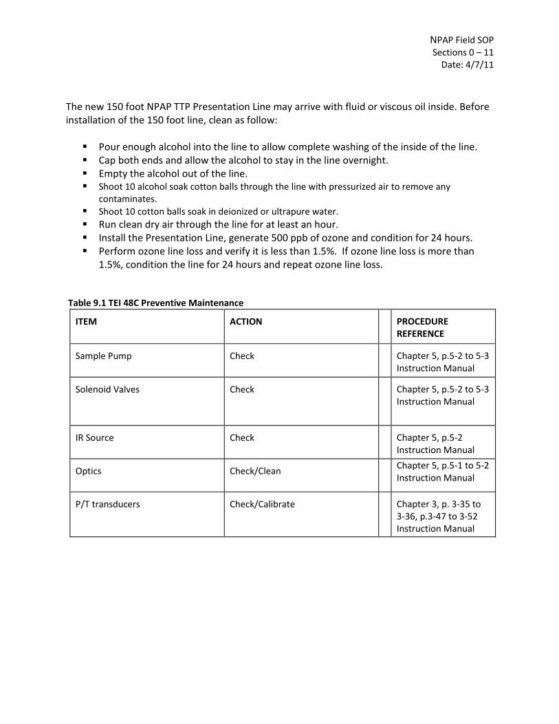
NPAP Field SOP Sections 0 – 11
Date: 4/7/11
The new 150 foot NPAP TTP Presentation Line may arrive with fluid or viscous oil inside. Before installation of the 150 foot line, clean as follow: Pour enough alcohol into the line to allow complete washing of the inside of the line. Cap both ends and allow the alcohol to stay in the line overnight. Empty the alcohol out of the line. Shoot 10 alcohol soak cotton balls through the line with pressurized air to remove any
contaminates. Shoot 10 cotton balls soak in deionized or ultrapure water. Run clean dry air through the line for at least an hour. Install the Presentation Line, generate 500 ppb of ozone and condition for 24 hours. Perform ozone line loss and verify it is less than 1.5%. If ozone line loss is more than
1.5%, condition the line for 24 hours and repeat ozone line loss.
Table 9.1 TEI 48C Preventive Maintenance ITEM
ACTION
PROCEDURE REFERENCE
Sample Pump
Check
Chapter 5, p.5-2 to 5-3 Instruction Manual
Solenoid Valves
Check
Chapter 5, p.5-2 to 5-3 Instruction Manual
IR Source
Check
Chapter 5, p.5-2 Instruction Manual
Optics
Check/Clean
Chapter 5, p.5-1 to 5-2 Instruction Manual
P/T transducers
Check/Calibrate
Chapter 3, p. 3-35 to 3-36, p.3-47 to 3-52 Instruction Manual

NPAP Field SOP Sections 0 – 11
Date: 4/7/11
Table 9.2 TEI 49 C-PS Preventive Maintenance ITEM
ACTION
PROCEDURE REFERENCE
Sample Pump
Check/Replace
Chapter 4, p. 4-3 Operator’s Manual
Solenoid Valve
Check/Replace
Chapter 4, p 4-3 Operator’s Manual
Lamp
Check/Replace
Chapter 4, p 4-2 Operator’s Manual
Optical Bench
Clean
Chapter 4, p 4-2 Operator’s Manual
P/T transducers
Calibration check
Chapter 5, p 5- 4; Chapter 6,
p 6-12 to 6-13 Operator’s Manual
Tabel 9.3 API 701 Preventive Maintenance
ITEM
ACTION
PROCEDURE REFERENCE
Charcoal
Check/Replace
p 5-13, 5-14 Operator’s Manual
Purafil
Check/Replace
p 5-13, 5-14 Operator’s Manual
HC Scrubber
Clean/Check
p 5-13,5-14 Operator’s Manual
CO Scrubber
Clean/Check
p 5-13,5-14 Operator’s Manual
Regen. Drier
Clean/Check
p 5-13,5-14 Operator’s Manual
Table 9.3 Powerware 9125 UPS
ITEM
ACTION
FREQUENCY
PROCEDURE REFERENCE
UPS
Keep the area around the UPS clean and dust-free.
If the atmosphere is very dusty, clean the outside of the system with a vacuum cleaner
User’s Guide, p45
Battery
For full battery life, keep UPS at ambient temperature (25° C or 77° F).
User’s Guide, p45

NPAP Field SOP Sections 0 – 11
Date: 4/7/11
ITEM
ACTION
FREQUENCY
PROCEDURE REFERENCE
Storing
If you store the UPS for a long period, recharge the battery by plugging the UPS into a power outlet.
Every 12 months. Recommend that batteries charge 24 hrs after a long-term storage.
User’s Guide, p45
Replace battery
Conduct a self-test by pressing and holding the Test/Alarm Reset button for three seconds. If the battery indicator stays on, contact your service rep to order. Consider all warnings, cautions, and notes before replacing batteries.
When battery indicator illuminates
Ref: Figure 15, p 27, User’s Guide
Table 9.4 Onan Generator
ITEM
ACTION
FREQUENCY
PROCEDURE REFERENCE
General Inspections
Check
Every day or every 8 hrs
p 16 Operator’s Manual
Engine Oil Level
Check
Every day or 8 hrs
p 17 Operator’s Manual
Battery
Clean/Check
Every month
p 19 Operator’s Manual
Spark Arrestor
Clean
Every 50 hrs
p 21 Operator’s Manual
Engine Oil & Filter
Change
After first 20 hrs Every 150 hrs
p 18 Operator’s Manual
Air Filter Element
Replace
Every 150 hrs
p 19 Operator’s Manual
Spark Plugs
Replace
Every 450 hrs
p 20 Operator’s Manual
Engine Cooling Fins
Clean
Every 450 hrs
Fuel Filter
Replace
every 450 hrs
Valve Lash
Adjust
Every 450 hrs
Cylinder Heads
Clean/Replace
Every 450 hrs

NPAP Field SOP Sections 0 – 11
Date: 4/7/11
Table 9.5 Duo-Therm Roof Top Air Conditioner
ITEM
ACTION
FREQUENCY
PROCEDURE REFERENCE
Air Filter
Remove the return Air Filter. Wash with soap and warm water. Dry and reinstall.
Periodically
p 9, Duo-Therm Installation & Operating Instructions
Air Box Housing
Clean air box housing and control panel with a soft cloth dampened with a mild detergent. Never use furniture polish or scouring powders
Periodically
p 9, Duo-Therm Installation & Operating Instructions
Fan Motor
Factory lubricated and requires no service under normal use.
p 9, Duo-Therm Installation & Operating Instructions
Frost Formation on Cooling Coil
If frost forms on the evaporator coil, inspect the filter and clean if dirty. Make sure air louvers are not obstructed. (Air conditioners have a greater tendency to frost when outside temperature is relatively low. This may be prevented by adjusting the thermostat control knob to warmer setting).
p 9, Duo-Therm Installation & Operating Instructions
Table 9.6 Wells Cargo Express Wagon
CHECK:
WHAT TO DO:
Every Trip
Every 3000 Miles
Every 6000 Miles
See p.# for details
Tire Air Pressure
Inflate to Proper Pressure Indicated on Sidewall
**
p.14 Owner’s Manual

NPAP Field SOP Sections 0 – 11
Date: 4/7/11
CHECK:
WHAT TO DO:
Every Trip
Every 3000 Miles
Every 6000 Miles
See p.# for details
Wheel Lugs Bolts & Nuts
Tighten to Proper Torque Specifications
**
p. 14 Owner’s Manual
Wheels
Check for Damage and /or Out of Round
**
p. 14 Owner’s Manual
Coupler Ball or 5th Wheel & Pin
Check for Sufficient Lube. Check Lock Mechanism. Check for Unusual Wear.
**
p. 15 Owner’s Manual
Safety Chains at Hitch Ball
Check for abrasion, distortion and general integrity of links
**
p. 16 Owner’s Manual
Coupler
Check for proper fastening & Hitch Pin in position and secure
**
p. 15 Owner’s Manual
Brakes
Check for proper adjustment & operation
**
p. 16 Owner’s Manual
Breakaway Switch
Test Switch Operation and Connections
**
p. 17 Owner’s Manual
Breakaway Battery
Pull Switch Pin, Check Charge Indicator Light
**
p. 17 Owner’s Manual
Doors, Windows & Roof Vents
Check all Windows/Doors/Roof Vents. Make sure all are closed & locked.
**
p. 18 Owner’s Manual
Load Distribution
Check load Distribution & Security
**
p. 18 Owner’s Manual
Leveling Jacks
Check Fastenings. Lube
**
p. 18 Owner’s Manual

NPAP Field SOP Sections 0 – 11
Date: 4/7/11
CHECK:
WHAT TO DO:
Every Trip
Every 3000 Miles
Every 6000 Miles
See p.# for details
Welds
Check All Weld Beads for Cracks or Separations.
**
p. 19 Owner’s Manual
Hinges
Grease zerks with a Lithium complex grease.
**
p. 19 Owner’s Manual
Tie-Down Devices
Check for fracturing, distortion and improper anchoring.
**
p. 19 Owner’s Manual
Electrical: Lights & Signals
Check to make sure all are working properly. Replace burned out bulbs.
**
p. 21 Owner’s Manual
Table 9.7 Dexter Axle
ITEM
ACTION
FREQUENCY
PROCEDURE REFERENCE
Brakes
Test that they are operational
At every use
p 5, 22 Operator’s Manual
Brake Adjustment
Adjust to proper operating clearance
3 months or 3000 miles
p 12 Operator’s Manual
Brake Magnets
Inspect for wear and current draw
6 months or 6000 miles
p 14 Operator’s Manual
Brake Linings
Inspect for wear or contamination
12 months or 12000 miles
p 15, 31 Operator’s Manual
Brake Controller
Check for correct amperage & modulation
6 months or 6000 miles
p 11 Operator’s Manual
Brake Cylinders
Check for leaks, sticking
12 months or 12000 miles
p 26, 31 Operator’s Manual
Brake Lines
Inspect for cracks, leaks, kinks
12 months or 12000 miles
p 31 Operator’s Manual

NPAP Field SOP Sections 0 – 11
Date: 4/7/11
ITEM
ACTION
FREQUENCY
PROCEDURE REFERENCE
Trailer Brake Wiring
Inspect wiring for bare spots, fray, etc.
12 months or 12000 miles
p 8 Operator’s Manual
Breakaway System
Check battery charge and switch operation.
At every use
p 7 Operator’s Manual
Hub/Drum
Inspect for abnormal wear or scoring
12 months or 12000 miles
p 32 Operator’s Manual
Wheel Bearings & Cups
Inspect for corrosion or wear. Clean & repack.
12 months or 12000 miles
p 34 Operator’s Manual
Seals
Inspect for leakage. Replace if removed.
12 months or 12000 miles
p 38 Operator’s Manual
Springs
Inspect for wear, loss of arch.
12 months or 12000 miles
p 41 Operator’s Manual
Suspension Parts
Inspect for bending, loose fasteners, wear.
6 months or 6000 miles
p 41 Operator’s Manual
Hangers
Inspect Welds
12 months or 12000 miles
p 41 Operator’s Manual
Wheel Nuts and Bolts
Tighten to specified torque values.
3 months or 3000 miles
p 47 Operator’s Manual
Wheels
Inspect for cracks, dents, or distortion.
6 months or 6000 miles
p 46 Operator’s Manual
Tire Inflation Pressure
Inflate tires to mfg=s
specifications.
Weekly
p 48 Operator’s Manual
Tire Condition
Inspect for cuts, wear, bulging, etc.
3 months or 3000 miles
p 49 Operator’s Manual
9.1.7.2 Corrective Maintenance
Corrective maintenance should be done per equipment manuals in the reference section. Spare parts for the Environics 9100 Calibrator, TEI 48C, TEI 49C-PS, and API 701 Zero Air Module are listed in Tables 9.8 – 9.11. Table 9.8 Spare Parts for Environics 9100 Parts # Description

NPAP Field SOP Sections 0 – 11
Date: 4/7/11
PC201 Transputer Board PC202 Analog Board PC203 Rom Board PC204 Comm/Driver Board (1 at Region 7) PC208 Motherboard (1 at RTP) PC210 Ozone Board (1 at RTP; 1 at Region 7) PC216 Status I/O Board PC224 Pressure Transducer Ozone Module (Lamp replacement) (1 at RTP; 1 at Region 7) Display Power Supplies and Power Entry Module
Table 9.9 Spare Parts for TEI 48C Part # Description 9831 Motherboard 9837 Processor Board 9849 Analog/Digital Board 9839 Digital/Analog Board 8931 Power Supply Board 8938 Detector Assembly (Preamplifier Board 7363) 9989 Input Board 8933 Bias Power Supply Board 8935 Temperature Control Board 9835 Clock Board 9936 Pressure Transducer 9934 Flow sensor 4735 Chopper Motor (1 at RTP; 1 at Region 7) 7336 Capillary - 18mil 8606 Pump Rebuild Kit (2 at RTP; 2 at Region 7) 8550 Pump 110V (Chuck suggested that since the pump is the same in both the CO and Ozone
instrument that maybe one pump (part number 8550) can be used for both instruments)) 8550 Sample pump(1 at RTP;1 at Region7) 7361 IR Source (1 at RTP; 1 at Region 7) 7336 Capillary (1 at RTP; 1 at Region 7) 4510 Fuse - T, 3A, 250V (115V) (1 at RTP; 2 at Region 7) 14009 Fuse - T, 25A, 250V (220V) 8606 Pump Rebuild Kit (KNF) 7368 Solenoid Valve (3 way) (1 at RTP)

NPAP Field SOP Sections 0 – 11
Date: 4/7/11
Table 9.10 Spare Parts for TEI 49C-PS Part # Description 9837 Processor Board 10761 Analog to Digital Board 9839 Digital to Analog Board 9956 Optional I/O Board 9843 C-Link Board 9833 Motherboard 9847 (#8595) Power Supply Board (1 #8595 at RTP; 1 at Region 7) 10758 Lamp Power Supply Board 8592 Detector System 10763 Lamp Block Heater 8540 Source Lamp (ozone free) 4124 Capillary - 15 mil (short purple) 9877 (8511) Pressure Transducer (#8511- 1 at RTP; 1 at Region 7) 9934 Flow Sensor 4509 Fuse - 2 amp slo-blo (1 at RTP) 8573 Solenoid Valve (1 at RTP) 8606 Pump Rebuild Kit 8550 Pump 110V 8540 Photometer Lamp (1 at RTP;1 at Region 7) 8573 Solenoid Valve (1 at RTP) 4124 Capillary - 15 mil 4111 Capillary - 28 mil 8606 Pump Rebuild Kit 4509 Fuse - 115V T, 2A, 250V 14009 Fuse - 220V T, 1.25A, 250V 8645 Ozonator Lamp (1 at RTP;1 at Region 7) 9994 Model 49C Primary Standard Instruction Manual Table 9.11 Spare Parts for API 701 Zero Air Module Parts # DESCRIPTION 005960000 Activated Charcoal, 6 lbs. 005970000 Purafil, 6 lbs., IZS or Valve VER. 006900000 Charcoal Retainer Pads M100/M200 006900100 Charcoal Retainer Pads M400 014340000 Valve, Shuttle, Drier 015450000 Assembly, Pressure Switch M701 015980000 M701 Expendables Kit 016880000 M701 Level 1 Spare Parts Kit (for 10 units) 016880100 M701 Spares Kit for 1 Unit 016920000 Mole Sieve, 11 ozs (CH033) 018490000 Pressure Gauge 017320000 HC Scrubber 021660000 PCA. Control Board Parts # DESCRIPTION

NPAP Field SOP Sections 0 – 11
Date: 4/7/11
024710000 Tubing: 6', 1/8" CLR 024780000 Tubing: 6', 1/4" OD 5/32" ID CLR FA0000006 Fan, 115Vac FL0000007 Filter, Coalescing FL0000015 Filter, Air 150LPM, M701 FL0000016 Filter Element Paper for FL015 HW0000101 Shock Isolator (Pump) KIT000040 Retrofit, HC Scrubber, M701 KIT000049 Retrofit, M701 CO Scrubber KIT000060 Leak Checker for M701 OR0000030 O-Ring, 2-141V OR0000035 O-Ring Drier Column OR0000059 O-Ring, Scrubber PU0000018 Pump, 115V/60Hz PU0000021 Pump, 220V/50Hz PU0000023 Pump Rebuild Kit SW0000017 Pressure Switch VA0000011 Valve, 4-way, Drier VA0000012 Valve, Pressure Relief VA0000014 Pressure Regulator VA0000016 Valve, CHECK VA0000017 Valve, 2-way (Water Drain) 015980000 M701 Expendables Kit (2 kits at RTP; 2 kits at Reg 7) 005960000 Activated Charcoal, 6 lbs. 005970000 Purafil, 6 lbs, IZS or Valve VER. 006900000 Charcoal Retainer Pads M100/M200 006900100 Charcoal Retainer Pads M400 016920000 Mole Sieve, 11 ozs (CH033) FL0000016 Filter Element Paper for FLO15 OR0000035 O-Ring, Drier Column OR0000059 O-Ring, Scrubber 016880000 M701 Level 1 Spare parts Kit (For 10 UNITS) INCLUDES: 014340000 Valve, Shuttle, Drier FA0000006 Fan, 115Vac FL0000007 Filter, Coalescing OR0000030 O-Ring, 2-141V VA0000011 Valve, 4-Way, Drier VA0000017 Valve, 2-Way (Water Drain) 016880100 M701 Spares Kit for 1 Unit (Non-Expendable 1 kit at RTP; 1 kit at Region 7) INCLUDES: FL0000007 Filter, Coalescing VA0000014 Pressure Regulator VA0000016 Valve, CHECK VA0000017 Valve, 2-Way (Water Drain)

NPAP Field SOP Sections 0 – 11
Date: 4/7/11
[This page intentionally left blank.]

NPAP Field SOP Sections 0 – 11
Date: 4/7/11
Field Standard Operating Procedures for the EPA Through The
Probe National Performance Audit Program
Section 10 Quality Assurance / Quality Control
SOP: NPAP-10
Name: Printed Signature Date
Contents
Section Page
10.1 Quality Assurance/Quality Control…………………………………………………………….10-clvii
10.1.1 Scope and Applicability ............................................................................................ 10-clvii 10.1.2 Summary of Method ................................................................................................. 10-clvii 10.1.3 Definitions ................................................................................................................ 10-clvii 10.1.4 Personnel Qualifications ........................................................................................... 10-clvii 10.1.5 Cautions .................................................................................................................... 10-clvii 10.1.6 Equipment and Supplies ........................................................................................... 10-clvii 10.1.7 Procedure .................................................................................................................. 10-clvii 10.1.8 References .................................................................................................................. 10-clxi

NPAP Field SOP Sections 0 – 11
Date: 4/7/11
[This page intentionally left blank.]

NPAP Field SOP Sections 0 – 11
Date: 4/7/11
10.1 Quality Assurance / Quality Control 10.1.1 Scope and Applicability
This SOP summarizes the Quality Assurance (QA) procedures and list Quality Control (QC) tasks that will be implemented at prescribed frequencies during routine NPAP TTP activities. 10.1.2 Summary of Method
This SOP summarizes the Quality Assurance (QA) procedures and lists Quality Control (QC) tasks that will be implemented at prescribed frequencies during routine NPAP TTP activities. For more information see the QAPP for NPAP, including TTP, on-line at the EPA TTN AMTIC website (http://www.epa.gov/ttn/amtic/npaplist.html).
10.1.3 Definitions
Appendix A contains a glossary of terms used in the NPAP TTP.
10.1.4 Personnel Qualifications
All personnel responsible for conducting EPA TTP PEs at field sites must be certified once per year by the U.S. EPA as completing required training to be eligible to conduct TTP PEs. All operators (those new to the program as well as experienced TTP Audit Lab operators) must be certified as attending a training program. During the training program, operators of the TTP Audit Lab must successfully complete an extensive, hands-on training session specified by EPA/OAQPS and pass both written and performance tests. A new operator must complete three (3) audit trips supervised by an experience operator approved by the regional TOPO/WAM before he or she is eligible to conduct TTP PEs.
10.1.5 Cautions
The TTP system components used for PE are potentially vulnerable to contamination and damaged. Exercise care in handling new components. Avoid touching the flow path component interior surfaces; normally handle the components only by touching the exterior surfaces. If details concerning component labeling and connection are not followed precisely, errors will result. Rough handling of used components during packaging or transport should be avoided. 10.1.6 Equipment and Supplies
A list of the required capital equipment and consumables is provided in Table 2-1 of NPAP TTP SOP Section 2. 10.1.7 Procedure
10.1.7.1 QA/QC Tables Two tables are included in this procedure. These tables summarize QA/QC performed to ensure NPAP TTP data quality meets program objectives. These tables also reflect how data should be evaluated in the validation process.

NPAP Field SOP Sections 0 – 11
Date: 4/7/11
Table 10-1 Critical Quality Control Checks summarizes the QC criteria that must be met to produce valid NPAP TTP audit data. These quality checks must be accomplished and verified prior to issuance of a preliminary audit report. If any of these criteria are not met, NPAP TTP audits should not proceed or a field report should not be issued. Table 10-2 Systematic Quality Control Checks summarizes QC evaluations completed to determine the effectiveness of the audit program. The result of these evaluations will be used to identify areas for program improvement and will be summarized in EPA Regional or National reports. 10.1.7.2 Completeness Completeness requirements for the NPAP TTP are as follow:
1 Primary QA organizations are required to complete audits of 20% of stations each year. 2 100% completeness (whatever it takes to report valid audits for 20% of stations each year)
3 All stations subject to an audit within 5 years.
10.1.7.3 Manifold Delivery System The ozone line loss test (NPAP TTP-3, Section 3.1.7.2) is performed quarterly to test the performance of the manifold delivery system. The presentation line shall be cleaned initially upon receipt and as needed thereafter according to procedure for cleaning the hose. (NPAP TTP-9, Section 9.1.7.1.1) 10.1.7.4 Field QC Checks Field QC checks are detailed in the relevant SOP sections. In general, these checks include: visual inspection of all regulators and meters for correct pressures and flows; examination of tubing and manifolds for visible contamination; check for hand-tightness of all connections; inspection of flowpath for any sign of crimping in the tubing; and confirmation of correct numerical values and expected position of all switches, readouts, valves, needle dial, and rotameter settings. Since all of the system should be under positive pressure, there should be no PE concentration problems from leaks. However, standard gases are too valuable to be wasted, and so a leak check using Snoop or equivalent may be done to confirm that no leaks have developed. The pressure remaining in the cylinders should be checked at the end of each audit to monitor for leaks. 10.1.7.5 CO Analyzer and Ozone Photometer Calibrations The NPAP TTP Audit Lab ozone standard should be verified against a Standard Reference Photometer (SRP) on a quarterly basis (NPAP TTP-3, Section 3.7.1.3).

NPAP Field SOP Sections 0 – 11
Date: 4/7/11
A three-point calibration is performed on-site at the beginning of every audit. A multi-point calibration should be performed on the NPAP TTP Audit Lab CO analyzer annually to verify the linearity of the instrument (NPAP TTP-3, Section 3.7.1.5). 10.1.7.6 Gas Cylinder Certification NPAP TTP Audit Lab compressed gas standards should be certified annually using the EPA Calibration Gas Traceability Protocol (NPAP TTP-3, Section 3.7.1.4). 10.7.1.7 Annual NPAP TTP Audit Lab Certification with Independent Standards On an annual basis, a certification of the NPAP TTP Audit Lab is performed by comparison to a set of independent analyzers calibrated against independent NIST traceable standards. 10.7.1.8 Data Validation Process This procedure describes the QA procedures that will be implemented to verify and validate field data Verification concerns the process of examining a result of a given activity to determine conformance to the stated requirements. Validation refers to examining a result to determine conformance to user needs.
10.7.1.8.1 Field Validation
Prior to issuance of the preliminary report, field PE data should be verified (NPAP TTP-7, Section 7.1.6.1).
10.7.1.8.2 Final Validation
EPA TOPO/WAM cross-check all primary and supporting data before finalizing the preliminary report (NPAP TTP-7, Section 7.1.6.2).
10.7.1.9 Annual Report On an annual basis, OAQPS will issue a report which summarizes the audits performed and effectiveness of the NPAP TTP program.

NPAP Field SOP Sections 0 – 11
Date: 4/7/11
Table 10.1 Critical Quality Control Checks Requirement Frequency Acceptance Criteria SOP
Reference Manifold Delivery System Visual defect check
each audit
See reference
NPAP TTP-4
Field QC Checks Zero Air Verification CO Calibration Flow Manifold Pressure Leak checks TTP CO/ O3 Instrument Stability
each audit each audit each audit each audit each audit each audit
0.5 ppm ± 0.1ppm Rotameter 0.3-0.4 LPM Rotameter 0.3-0.4 LPM Visible inspections 5 to 10 min. per point
NPAP TTP-6 NPAP TTP-6 NPAP TTP-6 NPAP TTP-6 NPAP TTP-6 NPAP TTP-4 NPAP TTP-6
Calibration/Verification of Sampler Ozone Line Loss Test Ozone standard calibration CO Calibration
quarterly quarterly prior to audit annually
<2.5% Average Loss < 3% slope from SRP ±2% each point
NPAP TTP-3 NPAP TTP-3 NPAP TTP-3
Standards Recertifications CO (High & Low) and Multi-blend
annually
New concentration
NPAP TTP-3
Table 10.2 Systematic Quality Control Checks
Requirement Frequency Acceptance Criteria SOP Reference
Data Completeness 20% of each PQAO sites All sites in 5 years
100%
NPAP TTP-10
Collocated Accuracy NPAP TTP Audit Lab Certification
once per year
All points ±5%
NPAP TTP-3
Field Scientist Re-Certification once per year Aware of proper NPAP TTP procedures Pass written (hands on tests)
NPAP TTP-1

NPAP Field SOP Sections 0 – 11
Date: 4/7/11
10.1.8 References
1. 40 CFR Parts 50 and 58. 2. Quality Assurance Handbook for Air Pollution Measurement Systems, Volume II Ambient Air Quality Monitoring Program, EPA-454/B-08-003, December, 2008. 3. Thermo Environmental Instruments, Inc. Instruction Manual for Model 48C. 4. Thermo Environmental Instruments, Inc. Instruction Manual for Model 49C-PS. 5. Environics Series 9100 Operating Manual. 6. Advanced Pollution Instrumentation, Inc. Instruction Manual for Model 701. 7. Powerware 9125, User’s Guide. 8. EPA Traceability Protocol for Assay and Certification of Gaseous Calibration Standards, EPA-
600/R-97/121, September, 1997.

NPAP Field SOP Sections 0 – 11
Date: 4/7/11
[This page intentionally left blank.]

NPAP Field SOP Sections 0 – 11
Date: 4/7/11
Field Standard Operating Procedures for the EPA Through The
Probe National Performance Audit Program
Section 11
Information Retention
SOP: NPAP-11
Name: Printed Signature Date
Contents
Section Page 11.1 Information Retention ..................................................................................................... 11-clxv 11.1.1 Scope and Applicability ............................................................................................ 11-clxv 11.1.2 Information Included in the Reporting Package ..................................................... 11-clxvii 11.1.3 Data Retention/Archive .........................................................................................11-clxviii 11.1.4 References ................................................................................................................ 11-clxix
Tables
11-1. NPAP Reporting Package Information ...................................................................................... 11-clxv

NPAP Field SOP Sections 0 – 11
Date: 4/7/11
[This page intentionally left blank.]

NPAP Field SOP Sections 0 – 11
Date: 4/7/11
11.1 Information Retention 11.1.1 Scope and Applicability
The Federal Records Act (44 U.S.C. 31) and other statutes require all federal agencies to create records that document their activities, file records for safe storage and efficient retrieval, and dispose of records according to Agency schedules. This SOP defines which records are critical to the project, what information needs to be included in reports, and which data reporting format and document control procedures should be used.
The following information describes the document and records procedures for the NPAP TTP field activities. In EPA’s QAPP regulation and guidance, EPA uses the term “reporting package.” This term is defined herein as all the information required to support the concentration data reported to EPA, which includes all of the required data, as well as any data deemed important by the NPAP. Table 11-1 identifies these documents and records by the Agency File Code (AFC) function and schedule numbers. It would be acceptable to have an overarching file called “NPAP TTP” for the purposes of locally delineating these files from other programs.
Table 11-1. NPAP Reporting Package Information
Agency File Code Category Record/Document Types
Function Number
301-093
006 Program Management Files
006.1
Management and organization
• Organizational structure for EPA and how the Regions and ESAT contractors fit into running the NPAP TTP
• Organizational structure for the support contractors
• NPAP Project Plans, and subsequent revisions • QMP
006.2
Monitoring site information
• Site characterization file (Site Data Sheets) • Site maps • Site pictures • SLT site contact information
006.3
Field operations and data acquisition (by EPA
Regional staff or contractors on behalf of
EPA)
• QAPPs • SOPs • Field logbooks and communications
006.4
Communications (contractor technical
project activity)
• Telephone records and e-mails between ESAT contractor and SLT agencies
• Telephone records and e-mails between ESAT contractor and the WAM/TOPO/DOPO

NPAP Field SOP Sections 0 – 11
Date: 4/7/11
Agency File Code Category Record/Document Types
Function Number
301-093 006.5
Communications (EPA project activity)
• Telephone records and e-mails between EPA Regional or Headquarters staff and SLT agencies and vice versa
• Telephone records and e-mails between EPA Regional and other EPA personnel (Headquarters to Regions and vice versa)
006.6
Equipment and instruments used by
contractors in the NPAP (records about charged
time to the support of the program would
reference AFC 405-202)
• Procurement logs • Inventories of capital equipment, operating
supplies and consumables • Repair and maintenance (e.g., vendor service
records, calibration records) • Retirement or scrapping
405 202 Contract Management Records
202.1 Contract administration • Work Assignments, task orders, delivery orders, and Work Plans
• Contractor monthly reports • Technical directives from the COR to the
contractor • Invoices for consumables • Requisite qualifications of FSs for NPAP TTP-
related, contractor-implemented activities • Training records and certificates of ESAT
contractors conducted and issued by the EPA Regional ESAT COR
404-142-01 179 Special Purpose Programs
179.1 Data administration and integration
• Data management plans and flowcharts • Raw data: any original data (routine and QC
data), including data entry forms • Data algorithms • Documentation of NPAP database
(national/Regional level) • NPAP data
404-142-01 173 Data Files Consisting of Summarized Information
173.1 Data summaries, special reports, and progress
reports
• Data, summary, and monthly field activity reports
• Journal articles, papers, and presentations • Data validation summaries

NPAP Field SOP Sections 0 – 11
Date: 4/7/11
Agency File Code Category Record/Document Types
Function Number
108-025-01-01 237 State and Local Agency Air Monitoring File
237.1 QA/QC Reports • 3-year NPAP QA reports • NPAP Data Quality Assessments • QA reports • Response and corrective action reports • Site audits
405 036 Routine Procurement
036.1 Acquisition of capital equipment and supplies by
EPA (either Headquarters or Regional office)
• Needs assessments and reports • Program copies of purchase requests • Requests for bids or proposals • Proposals, bids, or quotations • Bills of lading • Warranties and certificates of performance • Evaluations of proposals, bids, quotations, or
trial installations
403-256 122 Supervisors’ Personnel Files and Duplicate Official Personnel Folder Documentation
122.1 Personnel qualifications, training, and certifications
• WAM/TOPO/DOPO training certifications • Certification as an NPAP FS • Certification as an NPAP FS trainer
11.1.2 Information Included in the Reporting Package
11.1.2.1 Data Reporting Package Format and Document Control
The NPAP has structured its records management system according to EPA’s File Plan Guide (see http://www.epa.gov/records/tools/toolkits/filecode). A File Plan lists the records in your office and describes how they are organized and maintained. A good File Plan is one of the essential components of a recordkeeping system and is key to a successful records management program. It can help you:
Effectively document activities
Consistently identify records
Quickly retrieve records
Conduct disposition of records no longer needed
Meet statutory and regulatory requirements.
The NPAP Records Management System uses the AFCs to facilitate the easy retrieval of information during EPA TSAs and reviews. The NPAP Records Management System also follows EPA records schedules, which constitute EPA’s official policy on how long to keep Agency records (retention) and what to do with them afterwards (disposition). For more information on EPA records schedules, see
NPAP Field SOP Sections 0 – 11
Date: 4/7/11
http://www.epa.gov/records/policy/schedule (the Web site is searchable by AFC function and schedule numbers).
Table 11-1 lists the documents and records that will be filed according to the statute of limitations referenced in Section 11.1.4. To archive the information as a cohesive unit, all the NPAP information will be filed under the major code “NPAP,” followed by the AFC function and schedule numbers listed in Table 11-1. For example, NPAP Project Plans would be filed under the heading “NPAP/301-093-006.1.”
11.1.2.2 Field Notebooks
The NPAP will issue field notebooks to each FS. Each field notebook will be uniquely numbered and associated with the individual FS and the NPAP. Although data entry forms are associated with all routine environmental data operations, the field notebooks should be used to record additional information about these operations.
11.1.2.3 Field Binders
Three-ring field binders will be issued to each FS and will contain the inspection and maintenance forms, the appropriate data forms for routine operations, and the SOPs.
11.1.2.4 Communications
In addition to the Phone Communication Forms (COM-1) and the Monthly Progress Reports (COM-2), significant NPAP e-mail communications should be printed and filed according to the records schedule outlined in Table 11-1.
11.1.2.5 Electronic Data Collection
In addition to paper-based documents (e.g., notebooks, forms, binders), the NPAP also gathers much of its data electronically (e.g., strip chart data). Various printouts are made from these electronic systems, such as the audit spreadsheets used by the FS and others. Printouts that are determined to be permanent record (e.g., data which leads to significant findings or conclusions) should be filed as a data reporting package to ensure that all NPAP data are properly archived.
11.1.3 Data Retention/Archive
The information listed in Table 11-1 will be retained by the ESAT contractor for 4 calendar years (e.g., all data from calendar year 2002 will be archived through 12/31/2005). Upon reaching the 4-year archival date, the ESAT contractor will inform OAQPS that the material has met the archive limit and will ask for a decision on whether to continue archiving or to dispose of the material.

NPAP Field SOP Sections 0 – 11
Date: 4/7/11
11.1.4 References
1. U.S. EPA (Environmental Protection Agency). Implementation Plan: Through The Probe National Performance Audit Program.
2. U.S. EPA (Environmental Protection Agency). Quality Assurance Project Plan for the Through The Probe National Performance Audit Program.
3. 40 CFR Part 50.
4. U.S. EPA (Environmental Protection Agency). 2006. File Plan Guide. Available at: http://www.epa.gov/records/tools/toolkits/filecode.
5. U.S. EPA (Environmental Protection Agency). 2006. EPA Records Schedules. Available at: http://www.epa.gov/records/policy/schedule.

NPAP Field SOP Sections 0 – 11
Date: 4/7/11
[This page intentionally left blank.]