field installation quality assurance manual · field installation quality assurance manual ... 4.1...
TRANSCRIPT

FIELD INSTALLATION
QUALITY ASSURANCE MANUAL
GeoCHEM, Inc. - Phone: (907) 562-5755 ~ Toll Free: (800) 490.5320Washington State Sales - Phone: (206) 774.8777 ~ Fax: (206) 219.3740 Web Site: http://www.geocheminc.com

‐ 1‐
Contents
1 INTRODUCTION ..................................................................................................................................... 3
1.1 Purpose ......................................................................................................................................... 3
1.2 Scope of Quality Assurance ........................................................................................................... 3
1.3 Construction Meetings .................................................................................................................. 3
1.3.1 Progress Meetings ................................................................................................................. 3
1.4 Delivery, Storage, and handling .................................................................................................... 3
1.5 Equipment ..................................................................................................................................... 4
1.5.1 Welding Equipment .............................................................................................................. 4
1.5.2 Generators ............................................................................................................................ 4
1.5.3 Miscellaneous Equipment ..................................................................................................... 4
2 Geomembrane Installation ................................................................................................................... 4
2.1 Earthwork ...................................................................................................................................... 4
2.1.1 Surface Preparation .............................................................................................................. 4
2.1.2 Anchor Trench ....................................................................................................................... 5
2.2 Geomembrane Deployment ......................................................................................................... 5
2.3 Field Seaming ................................................................................................................................ 6
2.3.1 Seam Layout .......................................................................................................................... 6
2.3.2 Seaming Equipment and Products ........................................................................................ 6
2.3.3 Seam Preparation .................................................................................................................. 7
2.3.4 Trial Seams (Trial Welds) ....................................................................................................... 7
2.3.5 Panel Seams (Production Seaming) ...................................................................................... 7
2.3.6 Non‐Destructive Seam Testing. ............................................................................................. 7
2.3.7 Destructive Seam Testing ...................................................................................................... 9
2.3.8 Lining System Acceptance ................................................................................................... 12

‐ 2‐
3 ANCILLARY GEOSYNTHETICS INSTALLATION ....................................................................................... 12
3.1 Handling ...................................................................................................................................... 12
3.2 Deployment and Installation ....................................................................................................... 13
3.2.1 Geonet – Drainage Net ....................................................................................................... 13
3.2.2 Geotextile/ Geonet Geocomposite ..................................................................................... 13
3.2.3 Geotextile ............................................................................................................................ 13
3.2.4 Geosynthetic Clay Liner....................................................................................................... 13
3.3 Geosynthetic Repair .................................................................................................................... 13
3.3.1 Geonet – Drainage Net ....................................................................................................... 13
3.3.2 Geotextile/ Geonet Geocomposite ..................................................................................... 13
3.3.3 Geotextile ............................................................................................................................ 13
3.3.4 Geosynthetic Clay Liner....................................................................................................... 14
4 INSTALLATION FORMS ........................................................................................................................ 15
4.1 Inventory Checklist ...................................................................................................................... 16
4.2 Subgrade Acceptance .................................................................................................................. 15
4.3 Panel Placement Log ................................................................................................................... 15
4.4 Trial Weld Log ............................................................................................................................. 15
4.5 Seam Log ..................................................................................................................................... 20
4.6 Non‐Destructive Test/Repair Log ................................................................................................ 21
4.7 Destructive Test Log .................................................................................................................... 22
4.8 Certificate of Acceptance ............................................................................................................ 23

‐ 3‐
1 INTRODUCTION
1.1 Purpose Quality assurance refers to means and actions employed GeoCHEM, Inc. to assure conformity of the lining system installation with the Quality Assurance Plan, drawings and specifications.
This manual addresses the quality assurance of the installation of flexible membrane liners and other geosynthetic products used by GeoCHEM, Inc. in waste disposal landfills, surface impoundments or other installations as specified by the owner and/or Engineer. This manual is a general guide and not site specific, and delineates our quality procedures and standards for installation.
Commonly used geosynthetic components of a lining system are discussed in this manual. These include polyethylene geomembranes, geotextiles, geonets and geocomposites. This manual can be a useful guide in delineating the quality assurance procedures and requirements for the installation of all the above geosynthetic products.
1.2 Scope of Quality Assurance The scope of this manual includes quality assurance methods applicable to shipment, handling, and installation of all geosynthetics. This manual does not address design guidelines, installation specifications, or selection of geomembranes or other geosynthetics (which includes compatibility between geosynthetics and contained material).
This manual does not address the quality assurance of soils, except in cases where soil placement may have an influence on the geosynthetics.
1.3 Construction Meetings
1.3.1 Progress Meetings It is recommended an informal daily installation Progress Meeting be held among appropriate parties to discuss current progress.
1.4 Delivery, Storage, and handling Geosynthetic materials delivered to the site shall be unloaded prior to our crew arrival and stored with a minimum of handling. Each roll will be uniquely labeled.
Inventory shall be taken at the time of delivery. As the membrane is unloaded, it shall be inspected for damage. Any damage will be noted and repaired per specification. The Inventory Report form will be completed as material is delivered or when ILP’s crew arrives at the site. Any shortages or damaged material shall be noted on the Inventory Report.
‐ 4‐
Geosynthetic materials shall be handled with equipment that will not cause damage. The storage area shall be reasonably flat and well drained. The surface shall be free of sharp rocks or other objects that may damage the membrane.
The storage area must be as close as practical to the work area in order to minimize on site handling. The storage area must also be secure to prevent vandalism and theft and must be such that the material is not likely to be damaged by passing vehicles.
1.5 Equipment
1.5.1 Welding Equipment Two practical types of welding equipment can be utilized: Hot Wedge, and Extrusion.
1.5.1.1 Hot Wedge Welding For panel seaming, the installer shall provide automated welding equipment. The equipment shall be capable of measuring and controlling both the temperature at the wedge and the welding speed to ensure correct and consistent parameters are maintained during the welding process.
1.5.1.2 Extrusion Welding For extrusion welding, the installer shall provide a field extrusion welder capable of adhering a continuous bead between the panels with a nominal width of one inch. Extrusion welders shall have a fixed preheat nozzle attached to the front of the extrusion welder.
1.5.2 Generators Typically, a 6.5 Kw or larger generator will be used at the work area and electrical extension cords will be used to power the welding equipment.
The power source utilized for welding equipment shall be capable of providing constant voltage under a combined‐line load.
1.5.3 Miscellaneous Equipment Small tools will include hook blade utility knives, hot air tools, and angle grinders.
2 Geomembrane Installation
2.1 Earthwork
2.1.1 Surface Preparation

‐ 5‐
The Earthwork Contractor shall be responsible for preparing the subgrade according to the project specifications and the following minimum industry subgrade standard necessary to properly install the liner.
• The surface to be lined shall be prepared so as to be free of irregularities, protrusions, vegetation, standing water, loose soil or abrupt changes in grade.
• The supporting surface shall not contain stones or other matter of such composition, shape or size which may be damaging to the geomembrane and
• There are no excessively soft surface areas
Under no circumstances shall the installer deploy any geomembrane in areas not acceptable within these guidelines. A completed surface acceptance from shall be provided to the customer specifically indicating the areas accepted for geomembrane installation during each day’s activities. This form shall be provided after installation activities within that area. If at any time during the installation of the geosynthetic lining system the prepared subgrade deteriorates, becomes damaged, or in any way is determined to be unacceptable by the Site Supervisor, all liner installation work shall stop in those areas and the condition of those areas brought to the attention of the appropriate party.
2.1.2 Anchor Trench The anchor trenches shall be constructed by the Earthwork Contractor to the lines, widths and depths as shown on the drawings and specifications. This task should be performed prior to geomembrane deployment. Pile excavated dirt away from the area to be lined.
The edges where the geosynthetics enter the trench should be free of irregularities, protrusions, etc. to avoid potential damage to the material. Backfilling of the anchor trench shall be the responsibility of the Earthwork Contractor in accordance with specifications. Backfilling should occur when the geosynthetic material is at its most contracted state to avoid potential bridging problems. Care must be taken to avoid damaging the geosynthetics during backfilling.
2.2 Geomembrane Deployment Deployment of geomembrane or geosynthetic materials will be performed in a manner that complies with the following guidelines;
• Deployment equipment does not damage the subgrade or previously deployed geosynthetic materials.
• Personnel who are in contact with the liner do not smoke, wear damaging (non‐soft sole) shoes or engage in other activities which risk damage to the liner.
• Use of a low ground pressure, rubber‐tired all terrain vehicle (i.e. ATV) is allowed on the geosynthetic surface, provided proper care is taken to avoid damage and excessive traffic.
‐ 6‐
• Field panel placement installation sequence should take into account site drainage, wind direction, subgrade surface, access to the site, and production schedule of the project. Field panels should be seamed as soon as possible after deployment and all deployed material shall be marked with appropriate identification.
• Panels deployed will be marked with a unique identification number.
• Panels will be marked with the geomembrane manufacturer’s roll number.
• Panel numbers, roll numbers, and panel lengths will be recorded in the Panel Placement Log.
• Geomembrane panels will be ballasted during installation to prevent uplift by wind.
• The Site Supervisor and/or the QA Technician and the designated Independent Inspector shall visually inspect each panel as soon as possible after deployment for damage. Any damage found shall be marked for repair.
2.3 Field Seaming Field seaming involves the bonding of adjacent panels using thermal methods.
2.3.1 Seam Layout In general, seams shall be oriented parallel to the direction of maximum slope, i.e. oriented along, not across, the slope. In corners and odd‐shaped geometric locations, the number of seams should be minimized. No horizontal seams should occur on a panel less than five lineal feet from the toe of the slope. On slopes of less that 10% (6 H: 1 V), this rule shall not apply. A cross slope seam may be utilized provided the panel ends are cut at an angle of approximately 45 .
A seam is considered a separate entity if it is the principal attachment that joins two or more panels. Repairs are not considered seams in this context.
A numbering system using adjacent panel numbers shall identify each seam.
2.3.2 Seaming Equipment and Products Approved processes for field seaming and repairing are extrusion welding and fusion welding. All welding equipment shall have accurate temperature monitoring devices to ensure proper measurement of the welder temperatures.
2.3.2.1 Fusion Process This process shall be used for seaming panels together and is not generally used for patching or detailed work. The apparatus shall be of hot wedge type and is commonly equipped with a “split wedge” to allow air pressure seam testing.

‐ 7‐
Fusion welding equipment shall be self propelled devices and shall be equipped with functioning wedge temperature and seaming speed controllers to assure proper control by the Welding Technician.
2.3.2.2 Extrusion Process This process shall be used primarily for repairs, patching, and special detail fabrication. This method is also useful to connect new panels to previously installed liner that does not have an exposed edge capable of being fusion welded.
The extrusion welding apparatus (hand welder) shall be equipped with temperature monitoring devices.
2.3.3 Seam Preparation Seaming shall be performed in ambient temperatures between 35 F and 104 F. Ambient temperature is to be measured at least 6” from the surface of liner. The Welding Technician shall verify that prior to seaming the seam area is free of moisture, dust, sand, or debris of any kind; the seam is properly heat tacked and abraded when extrusion welding; and seams are aligned to minimize “fish mouths”.
2.3.4 Trial Seams (Trial Welds) Prior to production seaming, trial seams shall be made and accepted using project specified criteria. Trial seams shall be made on appropriate sized pieces of identical or equivalent geomembrane material to verify that seaming conditions and procedures are adequate. Five (5) one inch wide specimens will be tested from each trial weld sample. Each trial seam sample shall be assigned a number and the test results recorded in the Trial Weld Log.
Trial seams shall be performed for each welder to be used and by each operator of extrusion welders, and by the primary operator of each fusion welder.
A passing trial seam shall be made prior to the beginning of each seaming period. Typically this is at the start of the day and after lunch break.
Fusion welded trial seam samples shall be approximately six feet long by one foot wide with the seam centered lengthwise. For extrusion welding, the trial seam sample size shall be approximately five feet long by one foot wide with the seam centered lengthwise.
All specimens shall exhibit a film tearing bond.
2.3.5 Panel Seams (Production Seaming) Upon Acceptance of the trial seams, work may begin on deployed panels. All seams shall be labeled with seam number, welding technician identification, machine number, and the date and time the seam is welded. This information will also be recorded in the Seam Log along with lengths of welded seams. Seams will be welded on the same day panels are deployed.
2.3.6 NonDestructive Seam Testing.

‐ 8‐
ILP will non‐destructively test field seams for their full length using an air pressure test or a vacuum test. The purpose of non‐destructive tests is to demonstrate the absence of leaks in the seam.
The Site Supervisor shall schedule all non‐destructive testing operations in order to ensure prompt demonstration of weld quality and the orderly progress of the project.
The QA Technician shall ensure that any leaks found are marked for repair, and are retested when repairs are completed. All non‐destructive tests and repair locations will be recorded on the Non‐Destructive Test/ Repair Log.
2.3.6.1 Vacuum Testing Vacuum testing is routinely performed on extrusion welds and can be performed on the fusion welds. The equipment shall consist of a vacuum box assembly with a vacuum gauge, a pumping device, and a soap solution.
The following procedure shall be followed:
• Wet a section of the seam with the soap solution. The seam section must be longer that the vacuum box.
• Place the vacuum box over the wetted area and apply body weight to form a seal between the gasket and the liner.
• Evacuate air to create a negative pressure of approximately 5 psig.
• Observe, for not less than 10 seconds, the seam through the viewing window for soap bubbles emitting from the seam.
• If no bubbles are observed, reposition the box on the next wetted area for testing with slight overlap.
• If bubbles are detected, this indicates a leak in the seam, mark the area of the leak for repair, and retest after repairs are completed.
2.3.6.2 Air Pressure Testing Air pressure testing is performed on seams made by a double‐seam fusion welding apparatus.
The equipment shall be comprised of the following:
• An air pump, or air tank, capable of producing a minimum air pressure of 30 psig in the seam channel
• A sharp hollow needle to insert air into the air channel of the seam
• A hot air gun or other heating device to seal the ends of the air channel

‐ 9‐
The following procedures shall be followed:
• Seal both ends of the air channel of the seam to be tested.
• Insert the needle into the air chamber at either end of the seam to be tested.
• Pressurize the air channel to minimum of 30 psig. Allow the pressure to stabilize, and if necessary, re‐pressurize to 30 psig and note the pressure.
• With a minimum pressure of 30 psig stabilized in the air channel, the time of day should be noted.
• After approximately 5 minutes, the air pressure should be read again.
• If the difference between the two readings is more than 2 psig, the seam needs to be repaired and retested.
Upon completion of the air pressure test, the seam shall be marked and points requiring repair identified.
2.3.6.3 Procedures for Air Pressure Test Failure Should the seam fail the air pressure test, the following procedure shall be followed:
• Reposition the apparatus and retest the same section.
• While the seam air‐channel is under pressure, traverse the length of the seam and listen for the leak.
• While the seam air‐channel is under pressure, apply a soapy solution to the seam edge (do not trim excess material from edge of seam) and observe for bubbles formed by escaping air.
• Re‐test the seam in progressively smaller increments, until the area of leakage is identified.
• Repair the identified leak area by extrusion welding the excess material at the edge of the seam and then vacuum test.
• In areas where the air channel is closed and the integrity of the weld is not suspect, vacuum testing is acceptable.
2.3.7 Destructive Seam Testing Destructive seam testing will only be performed at selected locations, if required by Engineer’s specifications. The purpose of these tests is to evaluate bonded seam strength. Testing shall be performed as work progresses.
2.3.7.1 Location and Frequency

‐ 10‐
The frequency of sample removal is commonly no more that one sample per 500 lineal feet of seam.
2.3.7.2 Size of Samples A sample segment twelve inches by twelve inches shall be cut with the seam centered lengthwise. An additional segment of 12”x 18” shall be cut for independent lab testing, and a 12”x 12” segment for archival retain or other uses.
2.3.7.3 Sample Identification Each segment shall be marked with the appropriate destructive sample number.
2.3.7.4 Field Testing Samples shall be tested in peel and in shear using the following procedure:
• Ten specimens of one inch width shall be cut with a coupon cutter from the segment with a machine press and die.
• Five specimens shall be tested for peel. Fusion welds shall be tested from both sides.
• Five Specimens shall be tested for shear.
If specified, a field tensiometer will be supplied. Testing will occur at a rate of two inches per minute.
The results of all field destructive tests will be recorded in the Destructive Test Log.
2.3.7.5 Pass/Fail Criteria All specimens tested shall exhibit a film tear bond (FTB). For projects which utilize a tensiometer, the following table provides minimum acceptable values.
Seam Strength HDPE Geomembranes
Shear Peel
Thickness
(mils)
Extrusion
(Ib/in)
Fusion
(Ib/in)
Extrusion
(Ib/in)
Fusion
(Ib/in)
30 54 54 35 44
40 81 81 52 65
60 121 121 78 98
80 162 162 104 130
‐ 11‐
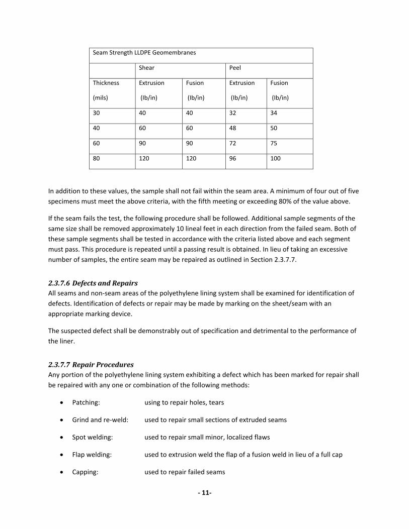
Seam Strength LLDPE Geomembranes
Shear Peel
Thickness
(mils)
Extrusion
(Ib/in)
Fusion
(Ib/in)
Extrusion
(Ib/in)
Fusion
(Ib/in)
30 40 40 32 34
40 60 60 48 50
60 90 90 72 75
80 120 120 96 100
In addition to these values, the sample shall not fail within the seam area. A minimum of four out of five specimens must meet the above criteria, with the fifth meeting or exceeding 80% of the value above.
If the seam fails the test, the following procedure shall be followed. Additional sample segments of the same size shall be removed approximately 10 lineal feet in each direction from the failed seam. Both of these sample segments shall be tested in accordance with the criteria listed above and each segment must pass. This procedure is repeated until a passing result is obtained. In lieu of taking an excessive number of samples, the entire seam may be repaired as outlined in Section 2.3.7.7.
2.3.7.6 Defects and Repairs All seams and non‐seam areas of the polyethylene lining system shall be examined for identification of defects. Identification of defects or repair may be made by marking on the sheet/seam with an appropriate marking device.
The suspected defect shall be demonstrably out of specification and detrimental to the performance of the liner.
2.3.7.7 Repair Procedures Any portion of the polyethylene lining system exhibiting a defect which has been marked for repair shall be repaired with any one or combination of the following methods:
• Patching: using to repair holes, tears
• Grind and re‐weld: used to repair small sections of extruded seams
• Spot welding: used to repair small minor, localized flaws
• Flap welding: used to extrusion weld the flap of a fusion weld in lieu of a full cap
• Capping: used to repair failed seams
‐ 12‐
• Topping: application of an extrudate bead directly to an existing weld
The following conditions shall apply to all the above methods:
• Surfaces of the polyethylene which are to be repaired by extrusion welding shall be lightly abraded to assure cleanliness
• All surfaces intended to receive extrudate must be clean and dry at the time of the repair
• All patches and caps shall extend at least four inches beyond the edge of the defect, and all patches shall have rounded corners.
2.3.7.8 Verification of Repairs Repairs shall be non‐destructively tested according to the criteria established in Section 2.3.6.
A passing non‐destructive test will be taken as an indication of an adequate repair. Failed tests indicate that the repair must be done again and re‐tested until a passing test result is achieved.
2.3.8 Lining System Acceptance After work is complete, the Site Supervisor and/or QA Technician shall conduct a final inspection (walk‐down) of the area for confirmation that all repairs have been appropriately performed, all test results are acceptable and the area has all scrap, trash and debris removed. Only after careful evaluation by the Site Supervisor and acceptance by the Customer shall any covering material be placed upon the lining system.
The geosynthetic lining system will be accepted by the customer when:
• Installation of materials is completed.
• Verification of the adequacy of all seams and repairs, including associated testing and documentation is completed.
Acceptance will be indicated by all parties involved by signing a Certificate of Acceptance (see Attached). Partial area of the installation may be accepted in order to allow further construction of the project.
3 ANCILLARY GEOSYNTHETICS INSTALLATION Geonet, Geotextile Geocomposite, and Geosynthetic Clay Liners
3.1 Handling All geotextile, geonets, and geocomposites shall be handled in such a manner as to ensure they are not damaged.

‐ 13‐
Sandbags shall be used to secure the edges of the material when the potential for wind damage is significant.
Cutting the material shall be done in such a manner as to prevent damage to any underlying or adjacent geosynthetic materials.
Care should be taken when deploying geosynthetic materials that stones, debris or other material is not trapped by the geonet, geocomposites, geotextile or geosynthetic clay liner which might damage the geosynthetics or geomembrane.
3.2 Deployment and Installation
3.2.1 Geonet – Drainage Net Geonet shall be overlapped approximately four inches and fastened together with plastic cable ties.
3.2.2 Geotextile/ Geonet Geocomposite The geonet component shall be overlapped approximately four inches and fastened together with plastic cable ties. The unbonded edge of the geotextile component shall remain overlapped.
3.2.3 Geotextile Geotextile may be installed by overlapping, by heat bonding (spot or continual basis) or by sewing as indicated in the specifications.
3.2.4 Geosynthetic Clay Liner Seaming of GCLs is achieved by overlapping the GCL panels approximately six inches. End‐of‐roll seams shall be overlapped a mnimum of 12”. Supplemental granular bentonite where recommended by the GCL manufacturer. The granular bentonite shall be applied at the rate recommended by the GCL manufacturer or as required by project specifications.
3.3 Geosynthetic Repair
3.3.1 Geonet – Drainage Net Any tear larger than twelve inches shall be repaired. Patches shall extend at least six inches from all sides of the tear and shall be fastened with plastic cable ties.
3.3.2 Geotextile/ Geonet Geocomposite Holes and tears in the composite material shall be repaired with a patch of identical or similar material extending at least 6” from all sides of the hole or tear and fastened with plastic cable ties.
3.3.3 Geotextile

‐ 14‐
Holes in geotextile material shall be repaired using a patch of identical or similar materials extending approximately six inches on all sides from the hole or tear and heat bonded to parent material.
3.3.4 Geosynthetic Clay Liner The area to be repaired (patched) must be free of contamination by foreign matter. Patches should overlap the damaged area by approximately twelve inches. For fabric‐encased GCLs, the patch is to be tucked into place with supplemental bentonite poured over the overlap. Temporary attachment of patches may be required to ensure that they are not dislodged when covering with geomembrane or soil.

‐ 15‐
4 INSTALLATION FORMS
4.1 Inventory Checklist
4.2 Subgrade Acceptance
4.3 Panel Placement Log
4.4 Trial Weld Log
4.5 Seam Log
4.6 NonDestructive Test/Repair Log
4.7 Destructive Test Log
4.8 Certificate of Acceptance

‐ 16‐
Inventory Check List Date: ________ Project: ____________________ Site Manager: ___________________ Project #: ____________________ QA Technician: __________________ Page: ______of_____ Material Roll # Date Used Material Roll # Date Used Material Roll # Date Used Material Roll # Date Used

‐ 17‐
SUBGRADE SURFACE ACCEPTANCE Customer: Date: Project Name: Project Number: Location: Partial: Final: I, the undersigned duly authorized representative of GeoCHEM, Inc., certify that upon visual inspection the subgrade surface described below meets criteria for installation of: By signing below, however, GeoCHEM, Inc. acknowledges no responsibility for the subgrade design, degree of moisture or compaction, integrity, elevation, or maintenance thereof, in any way. Approximate size of area accepted: Description of the area accepted:
GeoCHEM, Inc. Representative Owner/Contractor Inspector

‐ 18‐
Panel Placement Log Project Name: _______________________ Site Manager___________________ Location: _______________________ Material: ______________________ Job Number: ________________________ Sheet Thickness:________________ Q.A Technician: _____________________ Smooth: ______ Textured:_______ Panel Number
Roll Number
Deployment Date
Width (Feet)
Length (Feet)
Square Feet Smooth
Square Feet Textured
‐ 19‐
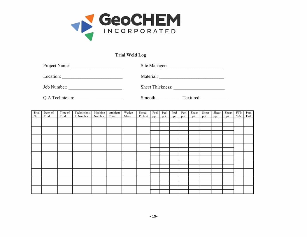
Trial Weld Log
Project Name: ______________________ Site Manager:________________________
Location: __________________________ Material: ____________________________
Job Number: _______________________ Sheet Thickness: ______________________
Q.A Technician: ____________________ Smooth:_________ Textured:___________
Trial No.
Date of Trial
Time of Trial
Technicians Id Number
Machine Number
Ambient Temp.
Wedge Mass
Speed Preheat
Peel ppi
Peel ppi
Peel ppi
Peel ppi
Shear ppi
Shear ppi
Shear ppi
Shear ppi
FTB Y/N
Pass Fail

‐ 20‐
Seam Log Project Name: _______________________ Site Manager___________________ Location: _______________________ Material: ______________________ Job Number: ________________________ Sheet Thickness:________________ Q.A Technician: _____________________ Smooth: ______ Textured: _______
Seam Number
Time of Weld
Date of Weld
Type of Weld
Length of Seam
Machine Number
Technician ID Number

‐ 21‐
Non-Destructive Test/ Repair Log Project Name: _______________________ Site Manager___________________ Location: _______________________ Material: ______________________ Job Number: ________________________ Sheet Thickness: ________________ Q.A Technician: _____________________
Seam Number
Test Date Technician ID Number
Test Type (A or V)
Air Pressure Test Psi Start Psi Finish
Test Result (P or F)
Repair Locations

‐ 22‐
Destructive Test Log
Project Name: Site Manager:
Fusion (ppi) Extrusion (ppi)
Location: Material:
Min. Peel
Min. Peel
Job Number Sheet Thickness:
Min. Shear
Min. Shear
Q. A. Technician: Smooth: Textured: Sample No.
Date Welded
Seam Number
Techician ID Number
Machine Type & No.
Location Peel ppi
Peel ppi
Peel ppi
Peel ppi
Peel ppi
Shear ppi
Shear ppi
Shear ppi
Shear ppi
Shear ppi
Shear Ppi
FTB Y/N
Pass/ Fail

‐ 23‐
CERTIFICATE OF ACCEPTANCE Project Name: Contract Number: Description of the Project:
Total Area: SF
I, the undersigned duly authorized representative of do hereby take over and accept the work described above from the date hereof and confirm that, to the best of my knowledge, the work has been completed in accordance with the specifications and the terms and conditions of the contract. There appears to be no damage to the plastic lining, nor any unacceptable interference with the surrounding works. Scrap and off-cuts have been removed and the work site has been left in a clean and tidy condition. GeoCHEM, Inc. undertakes to rectify any damage resulting from defective materials or workmanship within compliance of our standard installation warranty and the material manufacturer’s standard warranty and these warranties shall commence on the date below. The commencement of this warranty at this time shall not shorten the warranty period agreed upon in our written contract.
Name: Signature:
Title: Date:
Certified and accepted by GeoCHEM, Inc. Representative
Name: Signature:
Title: Date: