field-flow fractionation and hydrodynamic chromatography on a … · field-flow fractionation and...
TRANSCRIPT

Field-Flow Fractionation and Hydrodynamic Chromatography on aMicrofluidic ChipTyler N. Shendruk,‡ Radin Tahvildari,‡ Nicolas M. Catafard, Lukasz Andrzejewski, Christian Gigault,Andrew Todd, Laurent Gagne-Dumais, Gary W. Slater, and Michel Godin*
Department of Physics, University of Ottawa, MacDonald Hall, K1N 6N5 Ottawa, Canada
ABSTRACT: We present gravitational field-flow fractionation and hydrodynamicchromatography of colloids eluting through 18 μm microchannels. Using videomicroscopy and mesoscopic simulations, we investigate the average retention ratio ofcolloids with both a large specific weight and neutral buoyancy. We consider the entirerange of colloid sizes, including particles that barely fit in the microchannel andnanoscopic particles. Ideal theory predicts four operational modes, from hydrodynamicchromatography to Faxen-mode field-flow fractionation. We experimentally demonstrate,for the first time, the existence of the Faxen-mode field-flow fractionation and thetransition from hydrodynamic chromatography to normal-mode field-flow fractionation.Furthermore, video microscopy and simulations show that the retention ratios are largelyreduced above the steric-inversion point, causing the variation of the retention ratio in thesteric- and Faxen-mode regimes to be suppressed due to increased drag. We demonstratethat theory can accurately predict retention ratios if hydrodynamic interactions with themicrochannel walls (wall drag) are added to the ideal theory. Rather than limiting the applicability, these effects allow themicrofluidic channel size to be tuned to ensure high selectivity. Our findings indicate that particle velocimetry methods mustaccount for the wall-induced lag when determining flow rates in highly confining systems.
Field-flow fractionation (FFF),1,2 a broad class of separationtechniques, is achieved by imposing a transverse force f
across a channel of height h to a solution of solutes such ascolloids,3 macromolecules,4 or cells.5 A concentration gradientis established in response to the competition between thethermal energy, kBT, and the potential energy drop across thechannel, fh. The system can thus be described in terms of thedimensionless retention parameter, λ = kBT/fh. This solutedistribution is carried through a channel by a Poiseuille flowwith a characteristic retention ratio (average colloid velocitynormalized by average fluid velocity, R = ⟨ ⟩/⟨v⟩). Colloids ofdifferent sizes r have different concentration distributions andtherefore different retention ratios, R.This simple system possesses surprisingly rich elution
behavior. Previously, we considered the ideal retention theory(ignoring complications such as nonparabolic flow,6 nondiluteconcentration effects,7 slip,8 or hydrodynamic/lift interac-tions9), and predicted the existence of four distinct operationalmodes.10 The transitions between them were mapped;however, only three of the four modes and only a singletransition had ever been previously observed experimentally.For large λ, thermal energy dominates and solutes diffuse
across the entire channel. Only steric interactions with the wallslimit their distribution, as shown in Figure 1. This is thehydrodynamic chromatography limit of FFF (HC),11 wherelarger particles elute before smaller particles. Ideally, density-matched tracer particles used for micro-particle imagevelocimetry12 elute in HC, in the absence of any net externalbody forces.
If the potential energy dominates over the thermal energy,the concentration profile across the channel height becomesexponential. In this normal-mode field-flow fractionation(nFFF), ensembles of small solutes can loosely be thought ofas point particles subject to an external force that increases withparticle size r (nFFF in Figure 1). Therefore, larger particlesstay close to the accumulation wall where the lower flowvelocity causes them to move more slowly than smallerparticles.1 Experimental observation of the transition betweenHC and nFFF has not previously been reported.However, nFFF can only continue to exist for a certain size
range before the size dependence changes once again. Larger(heavier) particles are pushed against the wall and stericinteractions exclude the particles from sampling the slow
Received: March 17, 2013Accepted: May 7, 2013Published: May 7, 2013
Figure 1. Schematic of ideal field-flow fractionation operationalmodes.
Article
pubs.acs.org/ac
© 2013 American Chemical Society 5981 dx.doi.org/10.1021/ac400802g | Anal. Chem. 2013, 85, 5981−5988

moving velocity so larger particles elute faster in this steric-mode field-flow fractionation (sFFF), as seen in Figure 1.13
At the largest sizes, a significant portion of each particle’scross section is subject to varying fluid velocities. Ideally, evenlarge particles in flow profiles with no curvature, such asCouette flow, would possess the same velocity as the fluid atthe particles’ centers of mass. However, when the flow profilepossesses curvature and the particles’ size is comparable to thatcurvature, such as large particles in Poiseuille flows, then thevelocities can differ significantly from the velocity of the fluid atthe particles’ centers of mass. In such situations, a correction tothe Stokes’ law is required that causes larger particles to elutemore slowly than they would otherwise. Faxen’s law describesthis phenomenon. We have recently considered Faxen’s law inthe context of FFF and predicted the existence of the Faxen-mode field-flow fractionation (fFFF),10 but this new separationmode remains unverified by experiments or simulations. In thiswork, we experimentally and computationally demonstrate theexistence of fFFF but show that Faxen’s law is relativelynegligible at all particle sizes. We show that this is becauseincreased hydrodynamic friction due to interactions with thechannel walls play a more significant role at large particle-to-channel height ratios. We show that this is particularlyimportant in microfluidic systems.In field-flow fractionation, an external force is applied
perpendicular to the flow direction to create a soluteconcentration distribution. In a general sense, the externalforce scales with normalized particle size like f ∼ r α, where r =r/h and the power α differs for different types of FFF externalfields. For weight-based subtechniques, α = 3, while α = 1 forflow- or thermal-based FFF. Therefore, we can write λ = Λr−α,where the device retention parameter Λ characterizes the FFFapparatus.10 In the case of gravitational field-flow fractionation(GrFFF), Λ = (3kBT)/(4πGΔρh4) results from gravitationalacceleration, G, acting on colloids with a density difference Δρbetween the carrier fluid and particles. We have previouslypredicted that all four ideal operational modes can be describedby a single unified, ideal retention theory formula,10 namely
Λ = Λ
− −
Λ+ α
α⎛⎝⎜
⎞⎠⎟R r
rr
r rr( , )
6[1 2 ]
[1 2 ]2
( )(1)
In eq 1 , t h e Langev in f unc t i on i s g i v en by= −x x x( ) coth( ) 1/ and the second term is
= −
− ⎜ ⎟
⎧⎨⎪
⎩⎪⎛⎝
⎞⎠
rr r
r r( )
6 (1 ) if Faxen’s law is neglected
6 143
if Faxen’s law is accounted for
(2)
As mentioned, such an ideal theory neglects complications tothe flow profile (such as nonparabolic flow6 or slip8) and to themobility of the eluting particles (such as nonsphericalparticles14). Paramount among these, it does not take intoaccount hydrodynamic interactions that lead to wall-inducedincreased drag (wall drag).Experiments utilizing FFF can only avoid ambiguity in
determining solute size due to the nonmonoticity of eq 1, byworking in only one of the four modes (usually nFFF for itshigh selectivity). So far, the only mode transition observedexperimentally is the steric-inversion point between nFFF andsFFF.15−21 To highlight the validity of our theoretical treatment(eq 1), the results of five different nonmicrofluidic
subtechniques of FFF (thermal FFF,15 symmetric-flow FFF,16
asymmetric-flow FFF,17 hollow-fiber FFF,18 and GrFFF19)around the steric-inversion point are shown in Figure 2. A least-
squares fitting procedure that varies the device retentionparameter and the void time were used to determine the bestfits shown in Figure 2. Even for multiple scalings as shown (α =1 and 3), in all conditions, the ideal retention theory fits thetransition from nFFF to sFFF quite well regardless of Faxen’slaw: Dotted lines neglect Faxen’s law, while dashed linesinclude it. For the given normalized sizes the two forms of r( )are essentially indistinguishable. We conclude that in suchnonmicrofluidic situations, the correction due to Faxen’s law istrivial to include but of negligible importance.The ideal retention theory fits the data in Figure 2 well
because the particles are small relative to the channel height (r < 0.025, in all cases). When the particle sizes are larger, thetheories differ greatly for the different forms of r( ) in eq 2.The theoretically predicted retention curves for α = 3 and Λ
= 1.6 × 10⁻⁵ (strong field) and Λ = 10−3 (weak field) across theentire range of possible colloid sizes are shown in Figure 3 andFigure 4, respectively. Such theoretical curves have beendiscussed in detail10 and only a few important features must benoted: (1) When Faxen’s law is neglected (dotted lines), thesFFF regime extends to particles with a diameter equal to thechannel height and R(r → 0.5, Λ) → 1.5. However, whenFaxen’s law is properly included (dashed lines), fFFF appears,causing the retention ratio to peak and then slowly decrease toR(r = 0.5, Λ) = 1. (2) All four FFF modes are expected for Λ =1.6 × 10⁻⁵, but when Λ = 10−3, only HC and fFFF arepredicted. The ideal theory for Λ = 1.6 × 10⁻⁵ (dashed line inFigure 3) predicts that HC exists in the range of 0 < r < 0.023.After reaching a maximum, the slope of R(r, Λ) then changes tonegative through the range of 0.023 < r < 0.083. Thisrepresents nFFF, which exists until the steric-inversion point
Figure 2. Fit of eq 1 to a variety of FFF systems. Dotted lines ignoreFaxen’s law, while dashed lines account for it. In this range, the dottedand dashed lines overlap perfectly. Thermal FFF utilizes a temperaturegradient and α = 1. The data is for ΔT = 40 K (•15) and ΔT = 5 K(▼15). Symmetric (▲16), asymmetric (■17), and hollow-fiber (★18)FFF use a cross flow and have α = 1. For GrFFF, α = 3 (◆19). Datareproduced with permission from ref 15. Copyright 2004 Elsevier BV.Data reproduced with permission from ref 16. Copyright 1995 Wiley-VCH. Data reproduced with permission from ref 17. Copyright 2006Elsevier BV. Data reproduced with permission from ref 18. Copyright2002 Elsevier BV. Data reproduced from ref 19. Copyright 1992American Chemical Society.
Analytical Chemistry Article
dx.doi.org/10.1021/ac400802g | Anal. Chem. 2013, 85, 5981−59885982

(the global minimum at r = 0.083). The sFFF range is found for0.083 < r < 0.37, and it possesses a relatively small positiveslope. Beyond r = 0.37, an fFFF regime exists. On the otherhand, for Λ = 10−3 (dashed line in Figure 4), HC occurs for amuch larger range (0 < r < 0.14). There is then a large regimewith a relatively flat plateau (with only small variations in sloperepresenting negligible nFFF and sFFF) and an eventualreduction of the retention ratio R back down to unity. Thedetails of this behavior are discussed in ref 10.In this manuscript, we will use a microfluidic device to look
at the traditionally less accessible large particle/small channelregime. In microfluidic channels, separation of both particlesthat are minute compared to the channel height but alsoparticles that are comparable to the channel height are possibleand indeed routine.
■ EXPERIMENTAL SECTION
Experimental Methods. In order to explore the lessaccessible modes of field flow fractionation, our system mustelute ensembles of colloids that are significantly smaller than h,as well as others with diameters comparable to h. A microfluidicapparatus allows us to investigate the entire range of relativeparticle sizes. Miniaturized FFF systems have been usedpreviously,23−25 but never with such a relatively broad rangeof particle radii or such small channel heights. A section of ourmicrofluidic channel and two eluting colloids can be seen inFigure 5.
The benefits of performing FFF on a microfluidic chip(especially thermal FFF) have been well-documented,26 and ithas been suggested that microfluidic channels may help inpurifying, characterizing, and generally processing nanomateri-als.27,28 This work utilizes microfluidic devices to study theelution of particles that encompass the full range of sizes;however, we can envision FFF in future nanofluidicsystems.29,30 Current systems commonly utilize electrokinetic31
or confinement-based techniques,32 which have been partic-ularly successful in studying DNA,33−36 but nanofluidicHC37−40 and electric double layer methods41−45 have alsoproven viable. In such systems, one expects nonideal effects tobe even more pronounced. Indeed the importance of increasedhindrance has long been recognized in the nanofiltrationliterature.46−48 As we shall show, although they do not limit theapplicability of microfluidic or nanofluidic technology to FFF,nonideal effects of hydrodynamic interactions with channel
Figure 3. Experimentally determined retention ratios in a channel ofheight h = 18 ± 1 μm in a gravitational field (α = 3) are presented asclosed circles. Density difference between colloids and the carrier fluidis Δρ = 0.063 g cm−3. This density difference is equivalent to a deviceretention parameter of Λ = 1.6 × 10⁻⁵. Error bars represent thestatistical uncertainty on the mean, while the shaded area (bracketedby purple dashed−dotted lines) shows the uncertainty on theexperimental parameters about the theoretical prediction. Data pointspossess multiple colored error bars associated with each pair ofcoeluted colloids. The dotted line shows the ideal retention ratio whenFaxen’s law is neglected. The dashed line includes Faxen’s law. Theretention ratio that numerically accounts for increased drag coefficients(and Faxen’s law)22 is shown as a solid line.
Figure 4. Same as Figure 3 but for a small density difference betweencolloids and the carrier fluid of Δρ = 0.003 g cm−3 or equivalently adevice retention parameter of Λ = 10−3.
Figure 5. Top row: Sequential video microscopy frames of twocolloids eluting through a 18 μm high and 100 μm wide microfluidicchannel. The two colloids have a density difference of Δρ = 0.063 gcm−3, which is equivalent to Λ = 1.6 × 10⁻⁵ in dimensionless units.Each frame shows a larger 3.0 μm colloid moving with a slowervelocity represented by white dotted lines connecting its positionbetween frames and a smaller, faster 1.9 μm colloid. The time betweenshown frames is 50 ms. Bottom: Difference between laminar flowprofile in a rectangle channel, vR, that is 18 μ m high and 100 μm wideand the ideal Poiseuille (parabolic) velocity, v, normalized by theaverage ⟨v⟩. The flow only varies substantially from parabolic in thevicinity of the lateral walls. Dashed lines indicate the region beyondwhich events were disregarded.
Analytical Chemistry Article
dx.doi.org/10.1021/ac400802g | Anal. Chem. 2013, 85, 5981−59885983

walls must be accounted for when considering the elution ofparticles of sizes comparable to the channel height.Our microfluidic devices consisted of 40 mm long
polydimethylsiloxane (PDMS) elastomer (Sylgrad 184 fromDow Corning) channels fabricated using soft lithography basedon replica molding.49 The PDMS was replicated from a mastermold (SU8-10 MicroChem), created on silicon wafers. Eachsilicon wafer was cleaned using piranha etch then baked at 200°C for 30 min and let cool for 5 min. Spin speed and time werechosen based on final thickness requirements. The wafer wasthen prebaked at 65 °C for 2 min followed by 95 °C for 6 minand allowed to cool at least 5 min. It was then exposed to UV,with the maximum intensity of 16.18 mW cm−2 for 15 s andpostbaked at 65 °C for 1 min and 95 °C for 2 min. Finally, SU-8 developer removed the photoresist. All wafers were coatedwith aminosilane to facilitate PDMS removal.The PDMS with curing agent (10:1 mixing ratio) was poured
on the master mold and baked at 80 °C for 2 h. The curedPDMS was peeled off the mold to create the microchannelstructures. They were cut out, inlet holes were punched, anddevices were rinsed for 5 min in each of these solutions; soapywater, deionized water, ethanol, and isopropanol and treated inoxygen plasma (Glow Research AutoGlow) at 30 W for 30 sand bonded to the glass slides. They were then baked at 80 °Cfor at least 2 h afterward.50
Each microchannel has a width of 100 ± 10 μm and a heightof h = 18 ± 1 μm. All dimensions were confirmed by atomicforce microscopy and optical profilometry (MicroXAM-100).Pressure-driven flow was established through the channel, usingpressure regulators (Marsh Bellofram Type 10) and Solenoidvalves (SMC S070C-SDG-32), which were controlled byLabView (National Instruments). Experimental data was onlyrecorded once the flow rate stabilized. Stabilization againstpressure drift was verified by checking that the difference inmean velocities of a randomly selected sample of particles fromthe first quarter of a video set and sample from the final quarterwere significantly smaller than the standard deviation withineither set (typically differences varied by about 2% and wereonly a tenth of the standard deviation of either set).Polystyrene microparticles with nominal radii of r = {0.100 ±
0.005; 0.485 ± 0.005; 1.9 ± 0.1; 3.0 ± 0.2; 5.0 ± 0.4; 7.8 ±0.8}μm and density of ρp = 1.060 ± 0.002 g cm−3 (BangsLaboratories, Inc.) in 1% suspensions were diluted with thecarrier solution before injection. The density differencebetween that of the colloids and of the carrier fluid could beadjusted to control Λ. The base carrier fluid was an aqueoussolution containing 0.1% Contrex Alkaline51 (Decon Labo-ratories, Inc., PA, USA), to prevent nonspecific sticking andaggregation, with a density of ρc = 0.997 ± 0.001g cm−3.In some experiments, approximately 23% glycerol was added
to the carrier fluid to match the carrier density (ρcG = 1.063 ±0.002 g cm−3) to that of the colloids. The densities of all carrierfluids were measured using a suspended microchannelresonator (SMR).52 All experiments were conducted at roomtemperature (25 ± 1 °C). In the base carrier fluid, Λ = (1.6 ±0.4) × 10−5. When the particles are neutrally buoyant in theglycerol solution, Λ = (3 ± 2) × 10−3.Experiments were performed using pairs of colloids in order
to minimize uncertainty related to variability in carrier fluidvelocity between experiments, and relative retention ratios weremeasured. The movement of colloids through the channels wascaptured using video microscopy, and particle velocities were
obtained using custom analysis software. A brief series ofrepresentative frames are shown in Figure 5.A tracking program identified individual particles and
generated velocity distribution profiles for each particle sizebased on the Fourier transform of the position versus time data.Both programs, for capturing and tracking, were controlled byLabview (National Instruments). Between 150 and 200 eventswere considered in determining each data point. The smallestparticles (r = 0.1 μm) were analyzed semimanually due toautomatic tracking difficulties. In this case, captured videoswere analyzed frame by frame, by ImageJ (Image Processingand Analysis in Java), and the mean velocity was calculatedfrom the change in position along the channel versus time(Figure 5).Error bars in Figures 3 and 4 represent the statistical
uncertainty on the mean, while the shaded regions representthe uncertainty associated with the experimental parametersabout the numerically determined prediction (which will beintroduced in Results and Discussion). Because experimentalruns were performed using pairs of coeluting colloids, each datapoint (except the smallest and largest particles) has two errorbars representing the statistical uncertainty for each run. Theerror bar colors identify pairs in Figures 3 and 4.The aspect ratio, width to height, of the channel is
approximately 5:1. Although theory and simulations assumean infinite aspect ratio, as can be seen in Figure 5, the expectedflow profile of the carrier fluid in a rectangular microchannelonly differs from the Poiseuille flow profile near the lateralwalls. Therefore, the instances for which colloids were recordedwithin 5 μm of the lateral walls were disregarded, in case theyinteracted with the lateral walls. This near-lateral wall region ismarked in Figure 5 by dashed lines. If the entire rectangularchannel were considered, the percent difference between theaverage carrier fluid velocity and the Poiseuille flow assumptionwould be 11.6%. By disregarding flow within 5 μm of eachlateral wall, the percent difference is reduced to nearly half and84.3% of all points on the cross section of interest are within10% of the Poiseuille flow profile of the theory and simulations.Increasing the size of this region beyond 5 μm would requiremore events to be disregarded, resulting in a reduced statisticalcertainty.
Computational Methods. We have performed simulationsof spherical colloids embedded in a coarse-grained multiparticlecollision dynamics (MPCD) fluid.53,54 MPCD is ideal forstudying FFF in microfluidic devices because both hydro-dynamic interactions and thermal motion are intrinsicallypresent (i.e., MPCD is well-suited for situations involvingmoderate Peclet numbers55). A nonphysical, multiparticlecollision operator, which locally conserves mass, momentum,and energy, replaces a detailed description of the interactionsbetween fluid molecules. This operator ensures a Maxwell−Boltzmann velocity distribution and that the hydrodynamicequations of motion are obeyed over sufficiently long lengthsand times.56
Multiparticle collision dynamics simulations integrate themotion of fluid particles in two steps. The position xi(t) of eachMPCD fluid particle i is updated ballistically over a time step δtto become x i(t + δt) = xi(t) + vi(t)δt. Second, momentum istransferred between MPCD fluid particles through a multi-particle collision. The system is partitioned into cubic cells ofvolume a3 = 1, with each cell j containing on average ⟨nj⟩ =ρMPCDa3 = 5 particles. Each cell has a center of mass velocityvjCM(t) corresponding to the local mesoscopic fluid velocity
Analytical Chemistry Article
dx.doi.org/10.1021/ac400802g | Anal. Chem. 2013, 85, 5981−59885984

(each MPCD fluid particle has a mass m). To ensure Galileaninvariance is respected, a random vector shifts the cells eachtime step.57,58 The collision operator implements an Andersenthermostat such that the iterative scheme is
∑δ δ + = + + − v t t g t v t vn
v( ) ( )1
i j ij n
k
kCM RAN RAN
j (3)
where viRAN is a randomly generated velocity drawn from a
Maxwell−Boltzmann distribution and g is a constant accel-eration to generate the flow profile.59 Simple bounce-back rulesgovern collisions between MPCD particles and walls, althoughphantom fluid particles must be included in the collisionoperator of cells intersecting walls to ensure that artificialviscous thinning does not occur and that the no-slip boundaryconditions are respected.60,61 The system is periodic in x and z with the mean fluid flow in the x direction. Planar, channelwalls are in the ±y direction.The hard bead, representing the colloid, is a spherical mobile
wall, which also obeys bounce-back rules to create stericinteractions with the channel walls. The colloids of density ρ =(1000m)/(πa3) are subject to an external force in the y direction to simulate gravitational acceleration Gy. In order toefficiently simulate each operational mode, the box size isvaried, requiring that Gy and gx are varied to keep Λ strictlyconstant and Rep roughly constant. In all cases, the length ofthe system varies as 10 × r and the breadth as 5 × r. Fourchannel heights, h = {210, 90, 26, 15}[a] are used with the fourdevice retention parameters Λ = {∞, 1.87 × 10⁻⁴, 1.87 × 10⁻⁵,and 1.87 × 10⁻⁷}. Because the channel height changes, the fluidacceleration must change in order to keep Rep small androughly constant. For each channel height, we use the fluidaccelerations g = {10−4, 5.44 × 10⁻⁴, 6.52 × 10⁻³, 1.96 ×10⁻²}[δt−2ax ], respectively.However, we found that for the strongest forces used the
bead could become pinned to the wall with no fluid betweenthe particle surface and the plane. When this occurs, the beaddid not translate because bounce-back conditions ensure a no-slip boundary condition between the two surfaces. Thisunphysical situation is due to the discrete particle nature ofMPCD and demonstrates a limitation of the method. For thisreason, large beads in strong fields that had a null averagevelocity were rejected from the analysis.
■ RESULTS AND DISCUSSION
Experimental Results. The experimentally determinedretention ratios for colloids with Δρ = 0.063 g cm−3 are shownas circles in Figure 3. Since the absolute average carrier velocityis irrelevant and only relative changes in retention ratio aresignificant, the experimental values between size pairs werenormalized. To compare these data to the theoreticalpredictions, we chose one data point and normalized it to thetheoretical value. In this case, R (r = 7.8 μm, Δρ = 0.063 g cm−3
= 0.622) was chosen in order to produce the minimum χ 2. Inscaling the retention curve in this way, the retention ratio valuesfor r = 0.0056 and r = 0.0269 appear to be less than expected.The measured velocity difference between r = 0.0269 and r =0.106 is likely the most indefinite value because the fastest ofthe smaller particles may go unrecorded due to theexperimental challenges in tracking small, fast colloids. If themeasured difference is systematically less than the actual
difference, then the r = 0.0056 retention ratio will be artificiallyshifted downward.The data in Figure 3 is quite different from the ideal theory,
using either r( ) from eq 2 (dotted and dashed lines),especially in the case of large colloids. The experimentallyobserved retention ratio initially rises for HC then drops rapidlyfor nFFF. This is the first published observation of thetheoretically expected transition between HC and nFFF. Theminimum occurs at a larger particle size compared to theexpectations of ideal theory. Past nFFF and the steric-inversionpoint, the retention ratio is significantly less than predicted byeq 1 (dashed lines). In fact, the retention ratio remainsrelatively constant such that it is almost impossible to discernsFFF, and fFFF is not experimentally observed.As shown in Figure 4, when Δρ = 0.003 g cm−3 and the
transverse field is all but removed, the retention behavior ismuch different. In this weak-field case, the values of theexperimental retention ratio (squares) are set by normalizingthe r = 0.2761 value to R = 0.800. Without a strong transversefield, neither nFFF nor sFFF were predicted to exist, and this isindeed what is qualitatively observed in Figure 4. In fact, theretention ratio rises slightly to the global maximum at r ≈0.1075 through the HC regime and slowly decreases, thusqualitatively verifying the previously predicted fFFF operationalmode. However, the ideal, theoretical curves (dashed lines) failto predict the measured retention ratios in any quantitativesense. Just as in Figure 3, at all but the smallest particle sizes, eq1 severely overpredicts the retention ratio.Interestingly, eq 1 represents the literature data for FFF
channels with larger channel heights extremely well, as we sawin Figure 2, but fails for large colloids eluting throughmicrofluidic channels. This inadequacy arises because hydro-dynamic effects that are neglected in eq 1 must be consideredwhen the channel heights and particle diameters arecomparable. Accounting for wall-drag will be considered indetail in the Discussion and Interpretation of Results.Obviously, microfluidic systems include further nonideal
factors that can complicate the retention behavior, such as wallroughness or sticking events, the finite width of the channel,varying flow rates, nonspherical or nonmonodisperse particles,and variation in PDMS channel heights. Therefore, at this pointwe cannot be positively certain that the observed suppression ofthe retention ratio is definitively due to hydrodynamicallymediated colloid−wall interactions. To corroborate ourexperimental findings, we now consider our mesoscopicsimulations that quite naturally encompass complications dueto the confinement of mobile colloids in a flowing, thermal fluidbut yet are ideal in the sense that they do not possess theexperimental issues mentioned above.
Computational Results. Simulations of neutrally buoyantcolloids (Λ = ∞, blue circles in Figure 6) demonstrate that theretention ratio is indeed greater than unity for the vast majorityof particles (i.e., R > 1 in the hydrodynamic chromatographylimit). Simulations show two regions: for small particles, Rincreases, while for large particles, R decreases. MPCDsimulations agree with experimental findings and substantiatethe existence of fFFF in the weak fields. Furthermore,simulations of elution in weak external fields (Λ = 1.87 ×10⁻⁴, black squares in Figure 6) corroborate the experimentalobservation of the transition from HC to nFFF.When the field is nonnegligible, the retention curves possess
an nFFF region of steep descent after a brief HC climb. Thesimulation data for both Λ = 1.87 × 10⁻⁷ and 1.87 × 10⁻⁵ (red
Analytical Chemistry Article
dx.doi.org/10.1021/ac400802g | Anal. Chem. 2013, 85, 5981−59885985
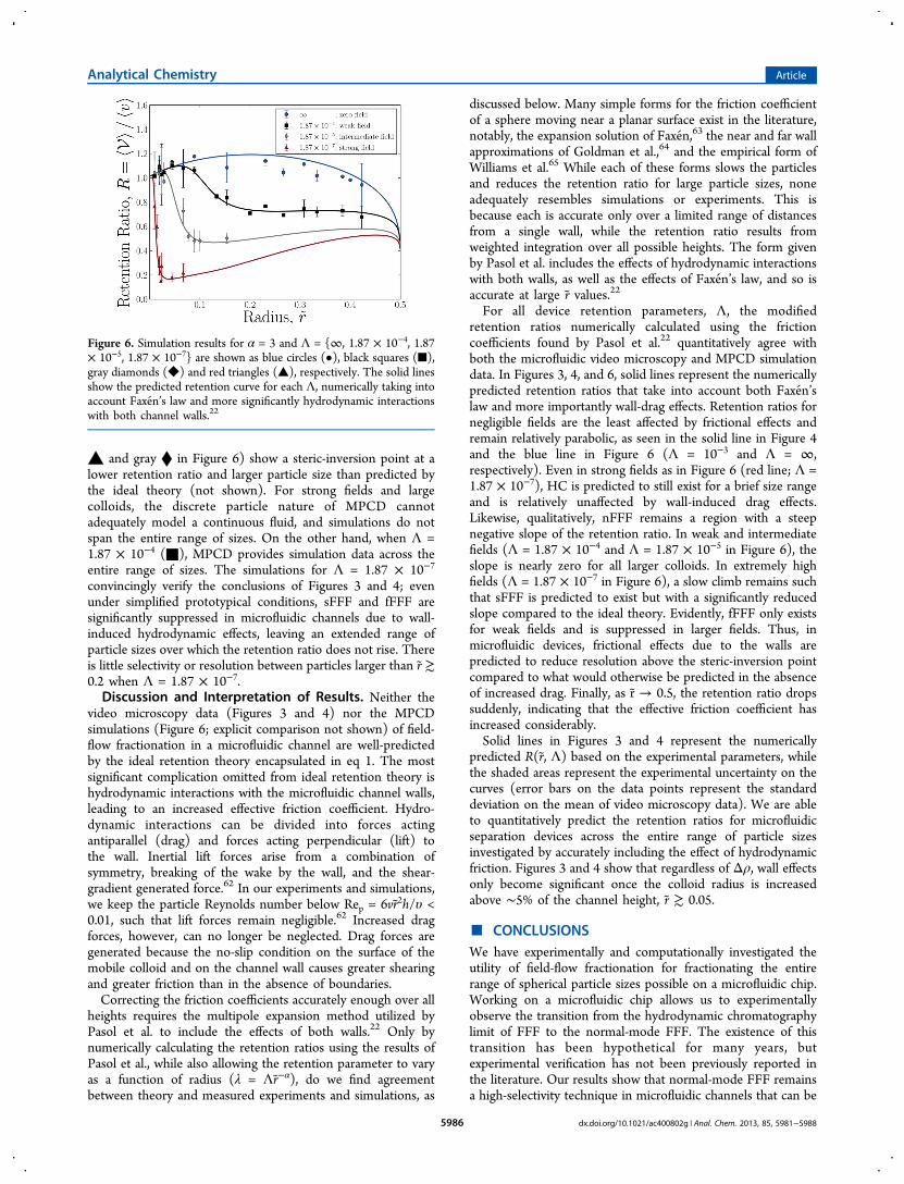
▲ and gray ⧫ in Figure 6) show a steric-inversion point at alower retention ratio and larger particle size than predicted bythe ideal theory (not shown). For strong fields and largecolloids, the discrete particle nature of MPCD cannotadequately model a continuous fluid, and simulations do notspan the entire range of sizes. On the other hand, when Λ =1.87 × 10⁻⁴ (■), MPCD provides simulation data across theentire range of sizes. The simulations for Λ = 1.87 × 10⁻⁷
convincingly verify the conclusions of Figures 3 and 4; evenunder simplified prototypical conditions, sFFF and fFFF aresignificantly suppressed in microfluidic channels due to wall-induced hydrodynamic effects, leaving an extended range ofparticle sizes over which the retention ratio does not rise. Thereis little selectivity or resolution between particles larger than r ≳0.2 when Λ = 1.87 × 10⁻⁷.Discussion and Interpretation of Results. Neither the
video microscopy data (Figures 3 and 4) nor the MPCDsimulations (Figure 6; explicit comparison not shown) of field-flow fractionation in a microfluidic channel are well-predictedby the ideal retention theory encapsulated in eq 1. The mostsignificant complication omitted from ideal retention theory ishydrodynamic interactions with the microfluidic channel walls,leading to an increased effective friction coefficient. Hydro-dynamic interactions can be divided into forces actingantiparallel (drag) and forces acting perpendicular (lift) tothe wall. Inertial lift forces arise from a combination ofsymmetry, breaking of the wake by the wall, and the shear-gradient generated force.62 In our experiments and simulations,we keep the particle Reynolds number below Rep = 6vr 2h/υ <0.01, such that lift forces remain negligible.62 Increased dragforces, however, can no longer be neglected. Drag forces aregenerated because the no-slip condition on the surface of themobile colloid and on the channel wall causes greater shearingand greater friction than in the absence of boundaries.Correcting the friction coefficients accurately enough over all
heights requires the multipole expansion method utilized byPasol et al. to include the effects of both walls.22 Only bynumerically calculating the retention ratios using the results ofPasol et al., while also allowing the retention parameter to varyas a function of radius (λ = Λr−α), do we find agreementbetween theory and measured experiments and simulations, as
discussed below. Many simple forms for the friction coefficientof a sphere moving near a planar surface exist in the literature,notably, the expansion solution of Faxen,63 the near and far wallapproximations of Goldman et al.,64 and the empirical form ofWilliams et al.65 While each of these forms slows the particlesand reduces the retention ratio for large particle sizes, noneadequately resembles simulations or experiments. This isbecause each is accurate only over a limited range of distancesfrom a single wall, while the retention ratio results fromweighted integration over all possible heights. The form givenby Pasol et al. includes the effects of hydrodynamic interactionswith both walls, as well as the effects of Faxen’s law, and so isaccurate at large r values.22For all device retention parameters, Λ, the modified
retention ratios numerically calculated using the frictioncoefficients found by Pasol et al.22 quantitatively agree withboth the microfluidic video microscopy and MPCD simulationdata. In Figures 3, 4, and 6, solid lines represent the numericallypredicted retention ratios that take into account both Faxen’slaw and more importantly wall-drag effects. Retention ratios fornegligible fields are the least affected by frictional effects andremain relatively parabolic, as seen in the solid line in Figure 4and the blue line in Figure 6 (Λ = 10−3 and Λ = ∞,respectively). Even in strong fields as in Figure 6 (red line; Λ =1.87 × 10⁻⁷), HC is predicted to still exist for a brief size rangeand is relatively unaffected by wall-induced drag effects.Likewise, qualitatively, nFFF remains a region with a steepnegative slope of the retention ratio. In weak and intermediatefields (Λ = 1.87 × 10⁻⁴ and Λ = 1.87 × 10⁻⁵ in Figure 6), theslope is nearly zero for all larger colloids. In extremely highfields (Λ = 1.87 × 10⁻⁷ in Figure 6), a slow climb remains suchthat sFFF is predicted to exist but with a significantly reducedslope compared to the ideal theory. Evidently, fFFF only existsfor weak fields and is suppressed in larger fields. Thus, inmicrofluidic devices, frictional effects due to the walls arepredicted to reduce resolution above the steric-inversion pointcompared to what would otherwise be predicted in the absenceof increased drag. Finally, as r → 0.5, the retention ratio dropssuddenly, indicating that the effective friction coefficient hasincreased considerably.Solid lines in Figures 3 and 4 represent the numerically
predicted R(r, Λ) based on the experimental parameters, whilethe shaded areas represent the experimental uncertainty on thecurves (error bars on the data points represent the standarddeviation on the mean of video microscopy data). We are ableto quantitatively predict the retention ratios for microfluidicseparation devices across the entire range of particle sizesinvestigated by accurately including the effect of hydrodynamicfriction. Figures 3 and 4 show that regardless of Δρ, wall effectsonly become significant once the colloid radius is increasedabove ∼5% of the channel height, r ≳ 0.05.
■ CONCLUSIONSWe have experimentally and computationally investigated theutility of field-flow fractionation for fractionating the entirerange of spherical particle sizes possible on a microfluidic chip.Working on a microfluidic chip allows us to experimentallyobserve the transition from the hydrodynamic chromatographylimit of FFF to the normal-mode FFF. The existence of thistransition has been hypothetical for many years, butexperimental verification has not been previously reported inthe literature. Our results show that normal-mode FFF remainsa high-selectivity technique in microfluidic channels that can be
Figure 6. Simulation results for α = 3 and Λ = {∞, 1.87 × 10⁻⁴, 1.87× 10⁻⁵, 1.87 × 10⁻⁷} are shown as blue circles (•), black squares (■),gray diamonds (◆) and red triangles (▲), respectively. The solid linesshow the predicted retention curve for each Λ, numerically taking intoaccount Faxen’s law and more significantly hydrodynamic interactionswith both channel walls.22
Analytical Chemistry Article
dx.doi.org/10.1021/ac400802g | Anal. Chem. 2013, 85, 5981−59885986

implemented with a simple channel design. By measuring theretention ratio of neutrally buoyant colloids in a microfluidicdevice, we have verified the existence of Faxen-mode FFF,though our results demonstrate that both fFFF and steric-modeFFF are substantially diminished in strong external fields. Instrong fields, Faxen-mode FFF becomes an inappropriateeponym because hydrodynamic interactions with the channelsproduce wall drag that increases the friction coefficients of thecolloids and dominates over the effect of Faxen’s law. While theideal retention theory works well for samples with hydro-dynamic radii significantly smaller than the separation betweenplates, video microscopy demonstrates that the ideal theory failsfor large colloids in microfluidic devices. Simulations verify thatthe ideal theory that neglects hydrodynamic complicationsoverestimates colloid velocity, particularly in the near-wallregion. Although including Faxen’s law is a simple improve-ment to the ideal retention theory, hydrodynamic forces actingantiparallel to the velocity of the colloids dominate in preciselythe regimes in which Faxen’s law would otherwise have beensignificant (steric- and Faxen-mode FFF). These wallinteractions increase drag and so decrease the retention ratiobelow the Faxen prediction. Moving in the vicinity ofmicrochannel walls causes the colloids to lag behind theirideally predicted speeds, which may have important con-sequences for particle tracking velocimetry techniques inmicrofluidic systems. Micro-particle image velocimetry implic-itly models the fluid velocity as equivalent to tracer particles’velocities; however, it is clear from the present study that thisassumption holds a significant risk of underestimating fluidvelocities, especially in micro- and nanoscale systems. Frictionaleffects must be rigorously accounted for in order to convertmicrobead velocities into accurate solvent velocity profiles, inparticular when dealing with particles greater than ∼5% of thechannel height. We find that the multipole expansion methodproduced values that accurately predict the retention ratio,while more traditional approximations fail.Although it seems at first glance that performing field-flow
fractionation in a microfluidic channel introduces morecomplications, there is a very clear benefit of incorporatingFFF components into microfluidic and into future nanofluidicdevices. When the external transverse field is strong, normal-mode FFF drops sharply to the steric-inversion point offeringan operational range with significant selectivity. However,rather than rapidly rising in steric-mode FFF and thusintroducing ambiguity through pronounced nonmonoticity, asoccurs in traditional, macroscopic FFF devices, the retentionratio is suppressed and nearly flat for all larger colloidal particlesizes. This quality can give researchers a clear signal that thesample is no longer eluting in the microfluidic device’s exclusiveoperating range.
■ AUTHOR INFORMATION
Corresponding Author*E-mail: [email protected].
Author Contributions‡These authors contributed equally. The manuscript waswritten through the contributions of all authors. All authorshave given approval to the final version of the manuscript.
NotesComputational resources were provided by Scinet andSharcnet. The authors declare no competing financial interest.
■ ACKNOWLEDGMENTS
This work was supported through NSERC Discovery Grants toM.G. and G.W.S. and the Canadian Foundation for Innovation(CFI) to M.G. Financial support of T.N.S from the NSERC-CGS program is gratefully acknowledged. We would like tothank J. Janca, T. Schauer, J. Luo, and M.H. Moon forgenerously granting permission to present their data.
■ ABBREVIATIONS
FFF, field-flow fractionation; HC, hydrodynamic chromatog-raphy; nFFF, normal-mode field flow fractionation; sFFF,steric-mode field flow fractionation; fFFF, Faxen-mode fieldflow fractionation; GrFFF, gravitational FFF; PDMS, polydimethylsiloxane; SMR, suspended microchannel resonator;MPCD, multiparticle collision dynamics
■ REFERENCES(1) Giddings, J. J. Chem. Phys. 1968, 49, 81−85.(2) Messaud, F.; Sanderson, R.; Runyon, J.; Otte, T.; Pasch, H.;Williams, S. R. Prog. Polym. Sci. 2009, 34, 351−368.(3) von der Kammer, F.; Legros, S.; Hofmann, T.; Larsen, E.;Loeschner, K. TrAC, Trends Anal. Chem. 2011, 30, 425−436.(4) Qureshi, R.; Kok, W. Anal. Bioanal. Chem. 2011, 399, 1401−1411.(5) Reschiglian, P.; Zattoni, A.; Roda, B.; Michelini, E.; Roda, A.Trends Biotechnol. 2005, 23, 475−485.(6) Sisson, R.; Giddings, J. Anal. Chem. 1994, 66, 4043−4053.(7) Janca, J.; Ananieva, I. A. J. Liq. Chromatogr. Relat. Technol. 2008,31, 2721−2736.(8) Slater, G. W.; Shendruk, T. N. J. Chromatogr., A 2012, 1256,206−212.(9) Town, R. M.; Duval, J. F. L.; Buffle, J. J. Phys. Chem. A 2012, 116,6421−6954.(10) Shendruk, T. N.; Slater, G. W. J. Chromatogr., A 2012, 1233,100−108.(11) Giddings, J. Sep. Sci. Technol. 1978, 13, 241−254.(12) Meinhart, C. D.; Wereley, S. T.; Santiago, J. G. Exp. Fluids 1999,27, 414−419.(13) Giddings, J.; Myers, M. Sep. Sci. Technol. 1978, 13, 637−645.(14) Song, M.; Sun, H.; Charmchi, M.; Wang, P.; Zhang, Z.; Faghri,M. Microsyst. Technol. 2010, 16, 947−954.(15) Janca, J.; Ananieva, I. A.; Menshikova, A. Y.; Evseeva, T. G. J.Chromatogr., B 2004, 800, 33−40.(16) Schauer, T. Part. Part. Syst. Charact. 1995, 12, 284−288.(17) Luo, J.; Leeman, M.; Ballagi, A.; Elfwing, A.; Su, Z.; Janson, J.-C.; Wahlund, K.-G. J. Chromatogr., A 2006, 1120, 158−164.(18) Min, B. R.; Kim, S. J.; Ahn, K. H.; Moon, M. H. J. Chromatogr., A2002, 950, 175−182.(19) Moon, M. H.; Giddings, J. C. Anal. Chem. 1992, 64, 3029−3037.(20) Moon, M. H.; Lee, K. H.; Min, B. R. J. Microcolumn Sep. 1999,11, 676−681.(21) Jensen, K. D.; Williams, S. R.; Giddings, J. C. J. Chromatogr., A1996, 746, 137−145.(22) Pasol, L.; Martin, M.; Ekiel-Jezewska, M.; Wajnryb, E.;Bławzdziewicz, J.; Feuillebois, F. Chem. Eng. Sci. 2011, 66, 4078−4089.(23) Gale, B. K.; Caldwell, K. D.; Frazier, A. B. IEEE Trans. Biomed.Eng. 1998, 45, 1459−1469.(24) Kang, D.; Moon, M. Anal. Chem. 2004, 76, 3851−3855.(25) Kantak, A. S.; Merugu, S.; Gale, B. K. Lab Chip 2006, 6, 645−654.(26) Janca, J. Int. J. Polym. Anal. Charact. 2006, 11, 57−70.(27) Ratanathanawongs Williams, S. K.; Runyon, J. R.; Ashames, A.A. Anal. Chem. 2011, 83, 634−642.(28) Sapsford, K. E.; Tyner, K. M.; Dair, B. J.; Deschamps, J. R.;Medintz, I. L. Anal. Chem. 2011, 83, 4453−4488.(29) Abgrall, P.; Nguyen, N. T. Anal. Chem. 2008, 80, 2326−2341.
Analytical Chemistry Article
dx.doi.org/10.1021/ac400802g | Anal. Chem. 2013, 85, 5981−59885987

(30) Sparreboom, W.; van den Berg, A.; Eijkel, J. C. T. Nat.Nanotechnol. 2009, 4, 713−720.(31) Wynne, T. M.; Dixon, A. H.; Pennathur, S. Microfluid. Nanofluid.2012, 12, 411−421.(32) Stavis, S. M.; Geist, J.; Gaitan, M. Lab Chip 2010, 10, 2618−2621.(33) Cross, J. D.; Strychalski, E. A.; Craighead, H. G. J. Appl. Phys.2007, 102, 024701.(34) Reccius, C. H.; Stavis, S. M.; Mannion, J. T.; Walker, L. P.;Craighead, H. G. Biophys. J. 2008, 95, 273−286.(35) Levy, S. L.; Mannion, J. T.; Cheng, J.; Reccius, C. H.; Craighead,H. G. Nano Lett. 2008, 8, 3839−3844.(36) Shendruk, T. N.; Hickey, O. A.; Slater, G. W.; Harden, J. L.Curr. Opin. Colloid Interface Sci. 2012, 17, 74−82.(37) Blom, M. T.; Chmela, E.; Oosterbroek, R. E.; Tijssen, R.; vanden Berg, A. Anal. Chem. 2003, 75, 6761−6768.(38) Chmela, E.; Blom, M. T.; Gardeniers, H. J. G. E.; van den Berg,A.; Tijssen, R. Lab Chip 2002, 2, 235−241.(39) Chmela, E.; Tijssen, R.; Blom, M. T.; Gardeniers, H. J. G. E.;van den Berg, A. Anal. Chem. 2002, 74, 3470−3475.(40) Kato, M.; Inaba, M.; Tsukahara, T.; Mawatari, K.; Hibara, A.;Kitamori, T. Anal. Chem. 2010, 82, 543−547.(41) Pennathur, S.; Santiago, J. G. Anal. Chem. 2005, 77, 6772−6781.(42) Pennathur, S.; Santiago, J. G. Anal. Chem. 2005, 77, 6782−6789.(43) Wang, X.; Wang, S.; Veerappan, V.; Byun, C. K.; Nguyen, H.;Gendhar, B.; Allen, R. D.; Liu, S. Anal. Chem. 2008, 80, 5583−5589.(44) Wang, X.; Liu, L.; Guo, G.; Wang, W.; Liu, S.; Pu, Q.; Dasgupta,P. K. TrAC, Trends Anal. Chem. 2012, 35, 122−134.(45) Griffiths, S. K.; Nilson, R. H. Anal. Chem. 2006, 78, 8134−8141.(46) Deen, W. M. AIChE J. 1987, 33, 1409−1425.(47) Bowen, W. R.; Mukhtar, H. J. Membr. Sci. 1996, 112, 263−274.(48) Dechadilok, P.; Deen, W. M. Ind. Eng. Chem. Res. 2006, 45,6953−6959.(49) Qin, D.; Xia, Y.; Whitesides, G. M. Nat. Protoc. 2010, 5, 491−502.(50) McDonald, J. C.; Duffy, D. C.; Anderson, J. R.; Chiu, D. T.; Wu,H.; Schueller, O. J. A.; Whitesides, G. M. Electrophoresis 2000, 21, 27−40.(51) Park, M. R.; Kang, D. Y.; Chmelik, J.; Kang, N.; Kim, J. S.; Lee,S. J. Chromatogr., A 2008, 1209, 206−211.(52) Godin, M.; Bryan, A. K.; Burg, T. P.; Babcock, K.; Manalis, S. R.Appl. Phys. Lett. 2007, 91, 123121.(53) Malevanets, A.; Kapral, R. J. Chem. Phys. 1999, 110, 8605.(54) Slater, G. W.; Holm, C.; Chubynsky, M. V.; de Haan, H. W.;Dube, A.; Grass, K.; Hickey, O. A.; Kingsburry, C.; Sean, D.; Shendruk,T. N.; Zhan, L. Electrophoresis 2009, 30, 792−818.(55) Gompper, G.; Ihle, T.; Kroll, D.; Winkler, R. In AdvancedComputer Simulation Approaches for Soft Matter Sciences III, Advances inPolymer Science, Holm, C., Kremer, K., Eds.; Springer: Berlin/Heidelberg, 2009; Vol. 221, pp 1−87.(56) Pooley, C.; Yeomans, J. J. Phys. Chem. B 2005, 109, 6505−6513.(57) Ihle, T.; Kroll, D. M. Phys. Rev. E 2001, 63, 020201(R).(58) Ihle, T.; Kroll, D. M. Phys. Rev. E 2003, 67, 066705.(59) Noguchi, H.; Kikuchi, N.; Gompper, G. EPL 2007, 78, 10005.(60) Lamura, A.; Gompper, G.; Ihle, T.; Kroll, D. M. EPL 2001, 56,319−325.(61) Lamura, A.; Gompper, G. Eur. Phys. J. E 2002, 9, 477−485.(62) Di Carlo, D.; Irimia, D.; Tompkins, R.; Toner, M. Proc. Natl.Acad. Sci. U.S.A. 2007, 104, 18892−18897.(63) Faxen, H. Ark. Mat., Astron. Fys. 1925, 19A, 22.(64) Goldman, A.; Cox, R.; Brenner, H. Chem. Eng. Sci. 1967, 22,653−660.(65) Williams, P. S.; Koch, T.; Giddings, J. C. Chem. Eng. Commun.1992, 111, 121−147.
Analytical Chemistry Article
dx.doi.org/10.1021/ac400802g | Anal. Chem. 2013, 85, 5981−59885988