field firing solutions delta v software - lextalus.comlextalus.com/pdf/ffs manual 4.8 - v.pdf ·...
TRANSCRIPT

Field
Firing
Solutions©
Delta V© Software
Version 4.8
Real-Time Ballistic Solutions©
Copyright©2004 - 2014 Lex Talus Corporation. All Rights Reserved
June 2014
Table of Contents Page
Introduction . . . . . . . . . . . . . . . . . . . . . . . . . . . . . . . . . . . . . . . 1 Instructional Videos . . . . . . . . . . . . . . . . . . . . . . . . . . 1 Operating System Requirements . . . . . . . . . . . . . . . 1 Terminology . . . . . . . . . . . . . . . . . . . . . . . . . . . . . . . . . . . 2 An Important Word about the DK . . . . . . . . . . . . . . 3 Hardware Buttons . . . . . . . . . . . . . . . . . . . . . . . . . . . . . 3 Functional Summary . . . . . . . . . . . . . . . . . . . . . . . . . . . 4
Core Data . . . . . . . . . . . . . . . . . . . . . . . . . . . . . . . . 4 User Preferences . . . . . . . . . . . . . . . . . . . . . . . . . 4 Refinements . . . . . . . . . . . . . . . . . . . . . . . . . . . . . . . 5 Support Tools . . . . . . . . . . . . . . . . . . . . . . . . . . . . 5
Preparation . . . . . . . . . . . . . . . . . . . . . . . . . . . . . . . . . . . . . . . . 7 Scope Calibration . . . . . . . . . . . . . . . . . . . . . . . . . . . . . 7 Zeroing the Scope . . . . . . . . . . . . . . . . . . . . . . . . . . . . . 8 Muzzle Velocity . . . . . . . . . . . . . . . . . . . . . . . . . . . . . . . 10 Calculate Muzzle Velocity (POI Method) . . . . . . 11 Calculate a Ballistic Coefficient . . . . . . . . . . . . 12
User Preferences . . . . . . . . . . . . . . . . . . . . . . . . . . . . . . . . . 13 Options Menu . . . . . . . . . . . . . . . . . . . . . . . . . . . . . . . . . 13 Wind or Target Direction . . . . . . . . . . . . . . . . . . . . . 14 Station versus Barometric Pressure . . . . . . . . . 14 Mils and MOA . . . . . . . . . . . . . . . . . . . . . . . . . . . . . . . . . 17 Positive Click Values . . . . . . . . . . . . . . . . . . . . . . . . . 17 Elevation Solution Significant Digits . . . . . . . . . 18 Working with the Uncoordinated Scope . . . . . . 18
Getting Started - The Basics . . . . . . . . . . . . . . . . . . . . . . . 19
Using the Refinements . . . . . . . . . . . . . . . . . . . . . . . . . . . . . 21 Wind Zones . . . . . . . . . . . . . . . . . . . . . . . . . . . . . . . . . . . 21 Spin Drift . . . . . . . . . . . . . . . . . . . . . . . . . . . . . . . . . . . . . 22 Powder Temperature . . . . . . . . . . . . . . . . . . . . . . . . . 23 Vertical Deflection . . . . . . . . . . . . . . . . . . . . . . . . . . 25 Coriolis Acceleration/Eötvös Effect . . . . . . . 25 Calculating a DK . . . . . . . . . . . . . . . . . . . . . . . . . . . . . 26
Support Tools . . . . . . . . . . . . . . . . . . . . . . . . . . . . . . . . . . . . . 30 Target Range Card . . . . . . . . . . . . . . . . . . . . . . . . . . . 30 Profiles . . . . . . . . . . . . . . . . . . . . . . . . . . . . . . . . . . . . . . 42
Atmosphere . . . . . . . . . . . . . . . . . . . . . . . . . . . . . . 42 Bullet . . . . . . . . . . . . . . . . . . . . . . . . . . . . . . . . . . . 44

Offsets . . . . . . . . . . . . . . . . . . . . . . . . . . . . . . . . . . 45 Rifle . . . . . . . . . . . . . . . . . . . . . . . . . . . . . . . . . . . . . 48 Solution . . . . . . . . . . . . . . . . . . . . . . . . . . . . . . . . . 50 Targeting . . . . . . . . . . . . . . . . . . . . . . . . . . . . . . . . 51 Turret . . . . . . . . . . . . . . . . . . . . . . . . . . . . . . . . . . . 51
Muzzle Velocity from Chronograph . . . . . . . . . . 57 POI Method - Muzzle Velocity in the Field . . . . . 57 Field Zero . . . . . . . . . . . . . . . . . . . . . . . . . . . . . . . . . . . . 58 Fixed Zero . . . . . . . . . . . . . . . . . . . . . . . . . . . . . . . . . . . . 58 Wind Speed at Range . . . . . . . . . . . . . . . . . . . . . . . . . . 60 Target Fix & Speed at Range . . . . . . . . . . . . . . . . . . . 61 The Elevation Table . . . . . . . . . . . . . . . . . . . . . . . . . . . 62 The Windage Table . . . . . . . . . . . . . . . . . . . . . . . . . . . . 64 Getting and Using Magnetic Bearing . . . . . . . . . . 65 Target Ranging . . . . . . . . . . . . . . . . . . . . . . . . . . . . . . . 67
Direct Ranging . . . . . . . . . . . . . . . . . . . . . . . . . . . 67 Map Ranging . . . . . . . . . . . . . . . . . . . . . . . . . . . . . 67 GPS Ranging . . . . . . . . . . . . . . . . . . . . . . . . . . . . . 68 Rangefinder Ranging . . . . . . . . . . . . . . . . . . . . 69 Reticle Ranging . . . . . . . . . . . . . . . . . . . . . . . . . . 72
The Projectile Metrics Button . . . . . . . . . . . . . . . 73 The Log Button . . . . . . . . . . . . . . . . . . . . . . . . . . . . . . . 73 The PS Button . . . . . . . . . . . . . . . . . . . . . . . . . . . . . . . . 74 Unit Conversion . . . . . . . . . . . . . . . . . . . . . . . . . . . . . . 75 Quick Access Data Lists . . . . . . . . . . . . . . . . . . . . . . 76
Offsets List . . . . . . . . . . . . . . . . . . . . . . . . . . . . . 76 Rifles List . . . . . . . . . . . . . . . . . . . . . . . . . . . . . . . 76 Targets List . . . . . . . . . . . . . . . . . . . . . . . . . . . . . . 77 Bullet Files . . . . . . . . . . . . . . . . . . . . . . . . . . . . . . 79
Calculating a Bullet’s BC . . . . . . . . . . . . . . . . . . . . 80 Bullet/Cartridge Databases . . . . . . . . . . . . . . . . . 82 LOS Metrics . . . . . . . . . . . . . . . . . . . . . . . . . . . . . . . . . . 82 Path Metrics . . . . . . . . . . . . . . . . . . . . . . . . . . . . . . . . . . 89 Kestrel® 4000 Series Interface . . . . . . . . . . . . . . 90 Advanced Directory Management . . . . . . . . . . . . . 93 Export/Import of Targeting Files . . . . . . . . . . . . 98 Using the Expression Calculator . . . . . . . . . . . . . 98 Updating Delta V . . . . . . . . . . . . . . . . . . . . . . . . . . . . . 100 Creating Printed Data Tables . . . . . . . . . . . . . . . . 101
FAQ & Troubleshooting . . . . . . . . . . . . . . . . . . . . . . . . . . 103
AppendixFunctional Outline . . . . . . . . . . . . . . . . . . . . . . . . . . . . . . . . . 1 File Naming Conventions . . . . . . . . . . . . . . . . . . . . . . . . . . . 4
Introduction
Field Firing Solutions© Delta V© runs on a small, hand-held PDA and is used toobtain a real-time firing solution in the field based upon current atmospheric and targetdata. The trajectory computation engine is the same as used in a larger desktopprogram, but has output generally limited to the specific information needed for acomplete firing solution: elevation, windage, lead, and hold-off. Elevation is given interms of an MOA or Mil adjustment and an actual turret solution; windage is output interms MOA or Mil for scope adjustment and/or for a wind correction hold-off witheither a mil-dot or MOA calibrated reticle; lead is the hold-off correction needed for amoving target given in terms of Mils or, optionally, in MOA (see Options). Theshooter will choose the appropriate units for his particular reticle.
Instructional Videos
The program is not “complex”, but it is complete with a number of tools usefulto the long range and ultra-long range shooter. Some tools require a fair amount oftime to generate or obtain the necessary data that will be input into the program. Thisdata is important, however, if the user expects to make hits on targets at range. Thismanual will aid in the user’s understanding of the software and its use. In addition,there are over 30 instructional videos on the Lex Talus website covering most aspectsof the software. An attempt was made to break the topics into discrete parts to permitvideos of ten to fifteen minutes in length and for the most part that objective wasachieved although a couple of the videos are somewhat more lengthy. The user isurged to view each video to gain a comprehensive understanding of how to use the Delta V software. After completing the videos and reading this manual, the usershould have an extremely good understanding of long range ballistics.
Operating System Requirements
Version 4 of the software is designed to run on the following operating systems:Windows Mobile 5.0, and above with Windows Mobile 6.0 being the preferredoperating system. In addition, .NET Compact Framework 2.0 must be loaded on thePDA. In newer PDAs this support software is part of the ROM but in the olderPDAs the software needs to be downloaded from Microsoft and installed. Thesoftware is available free from Microsoft and the link for the download can be foundon the Lex Talus website (www.lextalus.com) in the Support section.
1
Terminology: Accept, Abort, OK, Done, Close, Kill
As the user accesses the various pages and forms of the program, he will notethat closing the form is sometimes accomplished with a “Done” button or menu item;sometimes the menu provides a “Close” or a “Kill” option; most forms have an “OK”at the top of the page and most forms offer the user a choice of “Accept” or “Abort”. What do these words mean in the context of this program?
Forms that allow the user to input data that can be used by the program willalmost always have “Accept” or “Abort” as the menu items that will allow the user toclose the form and exit. “Accept” means to accept the data that is on the form andimport it back to the main part of the program for inclusion in the computation. “Abort” means to reject any data in the form and return to the previous displaywithout change. On forms that have an “OK” at the top, choosing OK is the same aschoosing “Abort”. The reason for this is to make the modification of existing data anunambiguous act on the part of the user. Where data can be accepted, the user mustaffirmatively “Accept” it.
On some forms there isn’t “Accept” or “Abort” options. These forms generallydo not import data back to the main part of the program. For example, the user canchoose to use the “Calculator” (Main page: Options, Tools, Calculators). When he isfinished, he simply clicks “Done” and the calculator closes. There is nothing toimport; the results of the calculation are left on that form and not used elsewhere. Acouple of the forms have a check box to enable the program to use the results of thecalculations made coupled with a “Done” button. Tapping the “Done” button willclose the form and if the user has so elected, the results of the work there will betransmitted back to the main part of the program.
Three of the forms have a “Kill” option to close the form - those related toGPS, Kestrel® and Rangefinder functions. These three forms have to do with gettingdata from outside the PDA through serial ports to various pages of the program. “Kill” means to kill all processes associated with receiving serial data, close the port,and close the form. However, it is possible to open a serial port and then close theform with those processes running in the background. When the user clicks the“Start” menu item he is activating a serial port which opens and awaits the receipt ofdata. At this point the “Kill” menu item changes to “Close” and should the userchoose to “Close” the form, the serial port remains open to continue data reception. In this way, other parts of the program can get GPS, Kestrel®, and Rangefinder datawithout the user having to be directly in the GPS, Kestrel®, or Rangefinder forms. These devices are essentially running in the background and the program is getting theincoming data, parsing it and distributing it to other parts of the program that use thisdata. To stop the processes, the user returns to the original form, selects the “Stop”
2
menu item at which time the “Close” menu item changes back to “Kill” and selecting“Kill” stops all related processes and closes the form.
An Important Word about the DK
Two shooters using the same rifle and ammunition in the identical conditionsmay have very different points of impact at range. Furthermore, the same shooter canexperience POI shifts due to a change in shooting technique. Even though muzzlevelocity remains the same, a change in components can cause a significant change inPOI. Or, manufactured ammunition can vary from lot to lot and result in a changedPOI. Even though this program does an extraordinarily good job in calculating downrange bullet velocities and times of flight, these calculations by themselves do notnecessarily account for point of impact because there are other factors at work thatinfluence exactly where the barrel is pointing at the moment of bullet launch. It isimportant for the user to understand that the DK is used to set the POI as predicted by the program tomatch the real life POI experienced at the range but only after the user has done the work to insurethat the variables input into the program are correct. Once the DK is set for a particularshooter and round, it will accurately predict trajectories for that ammunition, rifle andshooter - until the shooter changes something about that system. At that point thePOI of his rounds may change and he will have to adjust the DK accordingly to bringthe program and reality into alignment. Basically, the DK is there to personalize anindividual trajectory. It is the final modification to the program and should be basedonly on data obtained at a range where bullet velocity has dwindled to 1400 to 1200fps. It should not be used to modify the trajectory at higher velocities.
CAVEAT: Do NOT, DO NOT, DO NOT change the DK from its defaultvalue until 1) the scope has been calibrated, 2) the scope has been zeroed, 3) a muzzlevelocity has been obtained and verified via the POI method, and 4) a ballisticcoefficient has been calculated. Read the entire “Preparation” section below, completethe work outlined there before changing the DK. If you try to use DK to getagreement between the actual and calculated trajectories using erroneous muzzlevelocities and ballistic coefficients, the program will produce a distorted, inaccuratetrajectory. The DK was not intended for this purpose and will yield completelyunusable data. Don’t do it.
Hardware Buttons
Most Pocket PC type PDAs have hardware buttons that can be programmed (inaddition to the button cluster that generally controls the cursor and includes a centralbutton that functions as an Enter key.) The manufacturer of the PDA may dedicate
3

any or all of the hardware buttons to specific functions at which point the buttons willignore any attempt by the software to change or temporarily alter what the button doeswhen pushed. Delta V© attempts to program both the number 1 and 4 buttons aswell as the control cluster. In many of the forms, Button number 1 generally exits thecurrent form; Button number 4 usually performs the act of clicking the far right menuitem of the current form if there are only two menu items. On the main page Button 1activates the Presets forms (in the Presets form Button 1 exits the form and button 4has no function); Button 2 activates the Target Range Card; Button 3 activates theRifles list; and Button 4 activates the Offsets list. You can experiment with thevarious forms to see what, if anything, the buttons will do. If the PDA manufacturerhas hard coded the button to a particular function, it is possible that pressing thebuttons will have no effect in the program. If the manufacturer has allowed thebuttons to remain programmable, you will have to figure out what each button does;the position of the various buttons is not uniform among manufacturers.
Functional Summary 1
A. Core DataThe computation of a basic trajectory takes five sets of data:1. The density of the air through which the bullet will travel.
Specifically air pressure, temperature and humidity are needed;2. The muzzle velocity and ballistic coefficient of the projectile;3. The height of the scope above the center line of the bore and the
range at which the rifle is zeroed;4. The range of the target; and,5. The wind speed and direction.
That is all that is needed. This program can be used effectively to compute afiring solution and the user would not need to access any part of the program otherthan the main page for wind and range and the Presets page for atmosphere, bullet andscope variables.
The balance of the program is comprised of three other functional parts: Userpreferences, refinements, and support tools.
B. User PreferencesThe first five entries of the Options menu relate to user preferences. The user
can choose to use English or metric units of measure, MOA or Mils, degrees or the
1 For an outline of these points, see Attachment 1. It is suggested that going throughAttachment 1 is an excellent way to familiarize yourself with the software and to make sense of itsvarious attributes and features.
4

cosine2 for angled shots. There are a few other preference selections not on theOptions menu: Wind direction can be specified in degrees or by “clock” reference. The button labeled “From” directly below the wind speed data label on the main pageswitches from one to the other. Wind Speed can be selected in terms of (Imperial) feetper second, miles per hour or (Metric) meters per second, kilometers per hour. Targetspeed and direction are also subject to toggle buttons which alternate between degreesand hours (direction), miles per hour or feet per second (speed). On the Presets pagein the Atmosphere section, the user can choose to indicate the current atmosphericpressure either by specifying “Station” or “Barometric” pressure. The differencebetween the two are explained in the User Preferences section. Finally, next to theElevation solution window is a small button which sets the significant digits shown inthe solution and toggles between one and two significant digits.
C. RefinementsUsing the five data sets to calculate a trajectory will yield a decent solution, but
there are refinements to the solution that will increase the accuracy of the calculation. The first set of refinements can be found on the Options menu and are: Spin Drift,Powder Temperature, Vertical Deflection, Coriolis/Eötvös, and correcting forMagnetic Variation. In addition to these refinements to the solution calculation, thereis also the ability to specify multiple cross-wind zones on the Wind Vectors pageaccessed by the “Wind” button.
D. Support ToolsThe program incorporates numerous support tools to help the user make first
round, cold bore hits at range. The support tools include:1. Target Range Card - using GPS and range finder, rapid creation of a
target list from a specific FFP, including firing solutions in the form ofvertical and horizontal holds for each target (Targeting button)
2. Estimating wind speed at distance using the scope’s reticle and a windtimer (Wind button)
3. Estimate target speed at distance using the scope’s reticle and timer(Speed button, hold and release)
4. Target Table - access to saved firing and target locations (Targets button)5. Elevation Table (Elevation button)
a. Vertical holds, time of flight, wind and lead values6. Windage Table - extended wind values (Windage button)
a. Wind holds for changing winds7. Profiles (Profiles menu)
a. Atmosphere
2 There are also turret related preferences, “Use Turret Windage” and “Positive ClickValues”, but these will be explained in the section explaining how to build Turret Profiles.
5

b. Bulletc. Offsetd. Riflee. Solutionf. Turret
8. Ranging Tools (Ranging menu)a. Direct range file - using rangefinderb. GPS interface to process GPS data streamc. Map - creates position filesd. Rangefinder interface to process range finder serial dataf. Reticle - calculates range based upon target size
9. Field Zero (Options, Tools menu)10. Calculator (Options, Tools menu)11. DK calculator (Options, Tools menu)12. Muzzle Velocity calculator (Options, Tools menu)
a. Using a chronographb. Using the POI method
13. Scope Calibration Worksheet (Options, Tools menu)14. Loophole Worksheet (Options, Tools menu)15. Path Metrics (Max. Ordinate, Danger Space, PBI - Options, Tools menu)16. Miscellaneous
a. Profile Summary (Main page, “PS” button)b. Bullet and Cartridge database (Profiles menu)c. Visual Cues to State of Software
(1) Bearing (Coriolis)(2) GPS button(3) Muzzle Velocity - temperature adjusted (Presets)(4) Rangefinder button
d. Offset indicator (main page)e. Shot Log Buttonf. Subsonic bullet velocity indicator; subsonic range information
6

Preparation
To use this program effectively, the user must take some time to accuratelyobtain the necessary data used by the program in computing a firing solution. Thefirst important step the user must take is to calibrate his scope.
Scope Calibration
The program outputs two basic numbers that constitute a firing solution: theelevation angle that is necessary to launch the projectile in order to hit the target at aspecified range and the windage angle that the shooter must hold the rifle in order tocombat the effects of a cross-wind, spin drift and the Coriolis/Eötvös effects. Essentially the bullet is traveling in an arc and the point of the program is to predictwhere to aim such that the arc of the bullet intersects the line of sight exactly at thevertical plane of the target.
How does the user utilize the elevation and windage outputs? He either dialsthe elevation and windage using the scope’s turrets or employs a hold-off techniqueusing the scope’s reticle. Let’s focus on the first method here: dialing the necessarycorrection using the scope’s turrets. If the program tells a shooter that for a 1000 yardshot it is necessary to dial 38.5 MOA (11.2 Mil) from the scope’s zero, the shooter willsimply dial the elevation turret to 38.5 and call it good. But how does the shooterknow that he has actually moved the reticle 38.5 MOA? The truth is, he doesn’t. Mostshooters rely on the manufacturer’s representations that each click of the scope is equalto a specific MOA or Mil value. Most shooters never verify the click value of thescope. But if you ask experienced precision rifle instructors, they will tell you thatmost click values are not as represented. They will tell you that two shooters with thesame model scope from the same manufacturer will very commonly measuresignificantly different click values. What this means is that although the shooter thinkshe is dialing 38.5 MOA, the actual movement of the reticle may be 37 MOA or, morecommonly, something more like 39 MOA.
That is why the user of this software should spend a little time at the range tocalibrate his scope. How? Make a chart at least 45 inches in length with a heavy line atthe top and at measured distances down the chart.3 Put the chart on some kind ofcardboard or other suitable backing, place the chart at 100 yards or meters, secure thescope at the firing line so that the scope’s horizontal reticle element is at the zero line
3 Or you can print out scope calibration sheets that are in the “Documents” folder on theSD card. When placing the chart, make sure that you get an accurate measurement of the distancefrom the turret of the scope to the chart.
7

at the top of the chart, and dial in the elevation. As you dial, you’ll see the reticle movedown the chart. The chart should have about 45 MOA (13 Mil) and you should use allthat you can. After you have dialed in about 40 or so MOA, record where the reticle ison the chart. Repeat the process a few times to make sure that you have good data. Then, move the chart to the horizontal position and repeat the operation for windageusing the vertical element. Do both left and right windage over a total of around 20MOA (6 Mil). Once the data has been gathered, use the Scope Calibration tool(Options, Tools) to calculate the actual click values of the scope. At this point,accurate click values of both elevation and windage have been calculated and can beused when creating the turret profile described elsewhere in this manual. When theturret profile is created and used, the program will also have access to the actual clickvalues of the scope and will use the actual click values in computing what the turretsetting should be for elevation and windage. (Note that the program can output thecorrected elevation in terms of the elevation turret scale but that the windage willsimply be output in terms of the corrected Mil or MOA necessary to be dialed. Thereason why windage doesn’t have its own scale output is that windage is generally smallas compared with elevation and can be dialed directly without confusion.)
The chart should be mounted exactly straight up and down or exactly level whentracking the windage. The reason why is that in addition to calibrating the click value,the user will also be able to check that the reticle itself is tracking exactly vertically andnot tracking at an angle. To check this, make certain that the scope rail on the rifle islevel and then run the elevation up and down. At the extremes the center of the reticleshould track exactly vertical. If it doesn’t, the scope needs to be turned until the reticledoes track correctly; a failure to track vertically indicates that the scope is canted in itsrings and when the reticle is canted it is introducing a windage error that increaseslinearly with range.
The user of this software is urged to calibrate each and every scope he owns thatis used for long range shooting and thereafter to build a turret profile for each suchscope.
Zeroing the Scope
After calibrating the scope, the next step is to zero the scope after it has beeninstalled on a rifle. First, before installing the scope on the rifle, make sure that thereticle is centered, both horizontally and vertically. An easy way to do this is to cut acouple of “V” notches in a cardboard box that will hold the scope at the tube just foreand aft of the turrets. As the scope is manually turned the reticle will move up/downor side to side but will move less and less as the elevation and windage dials are turnedin the proper direction. At some point, the reticle should not move at all which means
8

that the reticle is in the mechanical center of the scope. For windage, this is exactlywhere the reticle should be as this will ensure that maximum windage, both left andright, is available to the shooter. Further, having the windage exactly centered is agood check that the scope base is properly aligned on the receiver. If after mountingthe scope the shooter finds that the rifle is printing a foot right at 100 yards, it will takealmost 12 MOA to correct which means that the correction is taken out of what isavailable for left windage. The reticle is now off center by 12 MOA. And, because thereticle is now off center, the total elevation available to the shooter has beencompromised. Therefore, after getting the windage exactly centered, try to keep it thatway by adjusting the scope base for any gross misalignment. Use the windage knobonly to “fine tune” the windage zero and try to be within 3 MOA or 1 Mil of the exactmechanical center of the scope.
After getting the reticle centered, zero the windage first at 50 yards.4 Why 50yards? Because nothing of significance happens to the bullet at 50 yards, even if thereis wind is blowing across the range. Get the bullet to exactly split the vertical line onthe target, then set the turret knob for wind to zero. At that point the shooter can beassured that any movement of the bullet off center is due to something other than amisaligned windage zero.
Getting an elevation zero is a little more complicated. The first place to zero isat 100 yards or meters. Realize that even if the rifle has a zero degree scope base,shooting the round at 100 yards will show a point of impact of 1.5 to 2 inches low. Why? Because the scope is mounted generally 1.5 to 2 inches above the centerline ofthe barrel, even if the barrel and scope are perfectly parallel to one another, the shooteris looking at a spot 1.5 to 2 inches above where the barrel is pointing. Discounting thesmall drop of a bullet at 100 yards due to gravity, the bullet must print below where theshooter is looking by the scope height above the bore centerline. Most long rangerifles use some form of canted or angled scope base, a 20 MOA scope base being verycommon. Mounting the scope on this type of base means that the shooter will belooking 18 or 19 MOA below where the barrel is pointing (20 MOA rail less the scopeheight.) So the first thing to do is dial the turret to move the bullet down by 18 or 19MOA. That should get both the scope and the rifle barrel looking at close to the samespot at 100 yards. Take a couple of well aimed shots to see what has to be done interms of getting the point of impact to meet the point of aim, adjust the scopeaccordingly and set the elevation turret to zero. The scope is now zeroed at that range.
Be very reluctant to change the windage zero that was obtained at 50 yards. Ifthe windage has changed due to the 20 MOA movement of the reticle, suspect that the
4 This assumes you are shooting a .30 caliber or less. Larger calibers will require a longerdistance. For example, a .338 Lapua can be zeroed for windage at 100 yards.
9

reticle is not moving straight up and down, that the scope is not square with respect tothe receiver. Some scopes have reticles that are canted and when the reticle elementslook square with the receiver these scopes will actually move the reticle at an angle. This will cause the point of impact of the bullet to move in the opposite direction ofthe cant; the more elevation that is dialed, the further the bullet will be moved over. Look for other explanations for an incorrect windage zero if the rifle is dead zero at 50yards. You may find that the scope has an internal tracking problem.
Muzzle Velocity
It is important that the user know as precisely as possible the muzzle velocity ofthe bullet he intends to use. A difference of 50 fps at the muzzle for a .308 Winchesterwith a 175 gr. SMK bullet translates into a 20 inch difference in point of impact at1000 yards and can be the difference between hitting and missing the target. Do notbelieve the muzzle velocity figures given by the manufacturer because that muzzlevelocity wasn’t measured in the user’s rifle. The user must get the data using his rifle,the current lot of ammunition he will be shooting and an accurate chronograph. Thereis no substitute for personally gathering this information. When obtaining the data, besure to note the temperature of the ammunition and try not to get the rifle too hot. What is required is a muzzle velocity that was produced by ammunition at a knownand recorded temperature. This information will be used later when creating a bulletprofile and will then be used by the program as it tries to adjust the muzzle velocitydue to atmospheric temperature changes. Throwing a cartridge into a hot chamberheats the powder and the resulting muzzle velocity recorded is that of powder that ispotentially hotter than the temperature recorded. This can only lead to errors later.
Be sure to use a decent chronograph. Since chronographs are not self-calibrating, the user is taking a lot on faith that the chronograph is accuratelymeasuring the bullet’s velocity. Use the highest quality of chronograph that is availableand, if possible, get velocity data from more than one chronograph. Be sure that thedata collected is accurate. Then use the program to compute the muzzle velocity(Options, Tools, Calculate MV) realizing that the velocity of the bullet measured 15 ormore feet from the muzzle is NOT the muzzle velocity - it is the velocity of the bullet15 or more feet from the muzzle. For the most accurate downrange trajectories, anaccurate muzzle velocity is required.
The program has a tool to check the chronograph and that is the “POI Method”tool (Options, Tools, Calculate MV) . After obtaining a good, measured muzzlevelocity, check the results by shooting at a target at around 300 to 600 meters. Notedistance the bullet is striking above or below the point of aim and use the POI Methodtool to calculate the actual muzzle velocity that accounts for the impact point. If the
10

chamber has cooled and cartridge is at ambient temperature, use the calculated muzzlevelocity. It is probably a better number than the data being generated by thechronograph. Remember this: the trajectory doesn’t lie; it is the actual manifestation ofthe various effects upon the bullet during flight and trumps all other theoreticalnumbers. If the trajectory doesn’t match the computations, re-check scope calibration,then suspect the muzzle velocity, then the ballistic coefficient in that order.
Calculate Muzzle Velocity by the POI Method
Using the chronograph muzzle velocity and the calculated ballistic coefficient,set up a target at around 400, 500 or 600 yards/meters, adjust the scope for the rangeof choice and fire five (5) carefully aimed shots. Measure the point-of-impact distanceabove or below the point-of-aim, open the POI Method tool (Options->Tools->Calculate MV->POI Method; see “POI Method - Muzzle Velocity in the Field” in thismanual) and compute the muzzle velocity as shown by the actual impact points on thetarget. Depending upon how well the user shoots and how small the resulting groupis, this is an extremely accurate way to determine muzzle velocity. Once the actualmuzzle velocity is known, first update the bullet profile with this known muzzlevelocity. Then, use the original muzzle velocity obtained from the chronograph anddivide by the POI Method muzzle velocity. This will give you an error factor. Usethat error factor to modify the down range velocity obtained from the chronographand that will give the actual down range velocity. Using these two corrected velocities,compute the ballistic coefficient again. (It is assumed here that whatever error existedwhen using the chronograph near the muzzle, that same error will be present at thedown range target. It is important, therefore, that the two measurements be taken atnear the same time and under the same conditions to maximize the chances that this istrue.)
Using this newly calculated ballistic coefficient, run through the process again: ifthe turret solution remains unchanged, assume the same POI distance on the targetand recalculate the muzzle velocity, get an error factor, using the error factor computethe down range velocity and using these two velocities calculate the BC for the bullet. It should be very close to the previous result. If the scope setting did change, theadjust the scope and fire five (5) more carefully aimed rounds at the target, measure thePOI versus POA distance and recompute the muzzle velocity, then proceed withobtaining an error factor, apply the factor to the down range velocity and recomputethe BC. At some point this iterative process will not produce any meaningful changein velocity and BC at which point the user can be very sure that he has a correctmuzzle velocity for that load/bullet and a BC that will produce optimum down rangeelevation and windage calculations well into the subsonic region.
11

The user may well be asking why it is necessary to go through all this work justto use the program. The answer is that it isn’t. But the user must understand that theprogram will assume the accuracy of all data that is input and based upon that data willprovide a firing solution. If the input data is erroneous, the resulting firing solutionwill be probably be erroneous as well. In order to discover the errors in the measuringdevices that shooters depend upon, it is necessary to check them and to makeallowances for their inaccuracies when detected. There really are no shortcuts in thisregard.
Calculate a Ballistic Coefficient
Now that you’ve got a calculated and verified muzzle velocity, take thechronograph and place it down range. How far? Far enough that the bullet willexperience a meaningful reduction of velocity but not so far as to risk hitting thechronograph. Depending upon the size of the bullet path opening, you should be ableto safely put bullets over the chronograph at 300 to 500 yards/meters. Fire a numberof rounds at this new range and obtain an average velocity for this bullet type. At thispoint, you can calculate a ballistic coefficient for the bullet that will be good for thisbullet into the subsonic region using this program. (Options->Tools->Calculate BC.) See Calculating a BC in this manual.
However , the work here is far from finished. As was mentioned, chronographsare not self-calibrating. The shooter has no idea if the chronograph is outputting datathat is accurate or merely “close” or, for that matter, not even close. If the muzzle anddown range velocities are off, the calculated BC for the bullet will be off as wellalthough the error will be proportionately less. So, for example, if the velocities arehigh by 10%, the calculated BC will be high by approximately 5%. Therefore it isnecessary that the user figure out if the chronograph is reporting accurate velocitiesand, if not, 1) determine the actual velocity for use in the bullet profile and 2) obtain anerror factor to recompute the down range velocity for purposes of computing a moreaccurate ballistic coefficient.
12
User Preferences
Options Menu
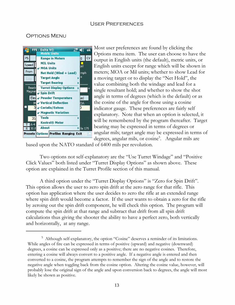
Most user preferences are found by clicking theOptions menu item. The user can choose to have theoutput in English units (the default), metric units, orEnglish units except for range which will be shown inmeters; MOA or Mil units; whether to show Lead fora moving target or to display the “Net Hold”, thevalue combining both the windage and lead for asingle resultant hold; and whether to show the shotangle in terms of degrees (which is the default) or asthe cosine of the angle for those using a cosineindicator gauge. These preferences are fairly selfexplanatory. Note that when an option is selected, itwill be remembered by the program thereafter. Targetbearing may be expressed in terms of degrees orangular mils; target angle may be expressed in terms ofdegrees, angular mils, or cosine5. Angular mils are
based upon the NATO standard of 6400 mils per revolution.
Two options not self-explanatory are the “Use Turret Windage” and “PositiveClick Values” both listed under “Turret Display Options” as shown above. Theseoption are explained in the Turret Profile section of this manual.
A third option under the “Turret Display Options” is “Zero for Spin Drift”. This option allows the user to zero spin drift at the zero range for that rifle. Thisoption has application where the user decides to zero the rifle at an extended rangewhere spin drift would become a factor. If the user wants to obtain a zero for the rifleby zeroing out the spin drift component, he will check this option. The program willcompute the spin drift at that range and subtract that drift from all spin driftcalculations thus giving the shooter the ability to have a perfect zero, both verticallyand horizontally, at any range.
5 Although self-explanatory, the option “Cosine” deserves a reminder of its limitations. While angles of fire can be expressed in terms of positive (upward) and negative (downward)degrees, a cosine can be expressed only as a positive; there are no negative cosines. Therefore,entering a cosine will always convert to a positive angle. If a negative angle is entered and thenconverted to a cosine, the program attempts to remember the sign of the angle and to restore thenegative angle when toggling back from the cosine option. Altering the cosine value, however, willprobably lose the original sign of the angle and upon conversion back to degrees, the angle will mostlikely be shown as positive.
13

Wind or Target Direction - Degrees versus Clock
There are two other preferences that require some explanation. On the maindisplay page the user can choose to display wind or target direction in terms of degrees(default) or, by pressing the “From” (or “Heading”) button, to switch to the clocksystem of wind or heading calls. Direction in terms of a clock face can be input interms of whole hours (and since each hour represents and additional 30 degrees, theuser will necessarily have to be satisfied with a wind call plus/minus 15 degrees),decimal hours or hours and minutes. For example, the user can input 10.5 or 10:30. The two are equivalent and both equal 315 degrees. When moving between the twoformats, degrees will be rounded to the nearest 0.5 degree. This is because theprogram rounds decimal degrees to the nearest whole minute. So converting 270.8degrees will be shown as 9:02 hours even though it is closer to 9:01.5 hours. Converting 9:02 hours back to degrees will yield 271 degrees, the correct conversion of9:02 hours. Both wind and target headings work the same way.
Station versus Barometric Pressure
The second of the two other preferences is the“Station versus Barometric Pressure” election foundin the Atmosphere section of the Presets page. Station pressure is the actual pressure at a particularlocation. Generally if the user has access to apressure measuring device, such as a Kestrel pocketweather meter, he can get the actual atmosphericpressure at his location and use that pressure in histrajectory computations. Barometric pressure isdifferent from Station pressure in that Barometricpressure has been “normalized” to sea level. This isthe pressure given by meteorologists on televisionweather stations. The reason for Barometric pressureis so that pressure maps of a region reflect thepressure as measured by a common scale. Forexample, the standard ICAO sea level pressure is29.92 inches of Mercury; in Denver at 5000 foot elevation, normal, standard pressure isless because the column of air being measure is 5000 feet shorter. The standard ICAOpressure for 5000 feet is 24.89 inches of Mercury. In other words, on a standard day inDenver, a 24.89 in. Hg. barometer reading would not be a low pressure reading; itwould be a normal reading and if Denver were to be magically moved to sea level, itspressure reading would be 29.92. So, for national weather forecasting on a normal dayin Denver, the pressure is shown as 29.92 in. Hg. so viewers can tell that the pressure
14
in the Denver area is neither high nor low, but equal to standard conditions.
How does the program use Barometric pressure? When the Barometricpressure preference is checked, the user is asked for both pressure and altitude. If auser learned that the weather station was reporting that Denver had a pressure of 29.92in. Hg., the user would input 29.92 for the pressure and 5000 feet for the elevation. The program would use the pressure and altitude to convert the Barometric pressureto the equivalent Station pressure and use that figure for computation purposes.
Clearly the most accurate pressure value is a measurement of pressure directly atthe user’s location, i.e., Station pressure. If for some reason Station pressure is notavailable, the next best data is Barometric pressure, which is widely available inbroadcasts, plus the elevation of the user’s location (generally obtainable from maps.) The Barometric pressure obtained in this manner will be approximate becauseBarometric pressure is generally broadcast for a large area. But, it is better than acomplete guess.
The program’s default is to use Station pressure as it is the most accurate; theprogram was written to be practical so the Barometric pressure as an option wasincluded. But the user is urged to acquire a means of measuring the pressure andtemperature where the shot is to be taken. This information is necessary not only forthe calculation of a trajectory, but is necessary to fix a zero for a scope (as explained inthe Fixed Zero section.) And getting an accurate temperature is important for buildinga bullet profile and being able to alter the muzzle velocity based upon temperaturechanges. Get some device that can accurately measure both temperature andatmospheric pressure.
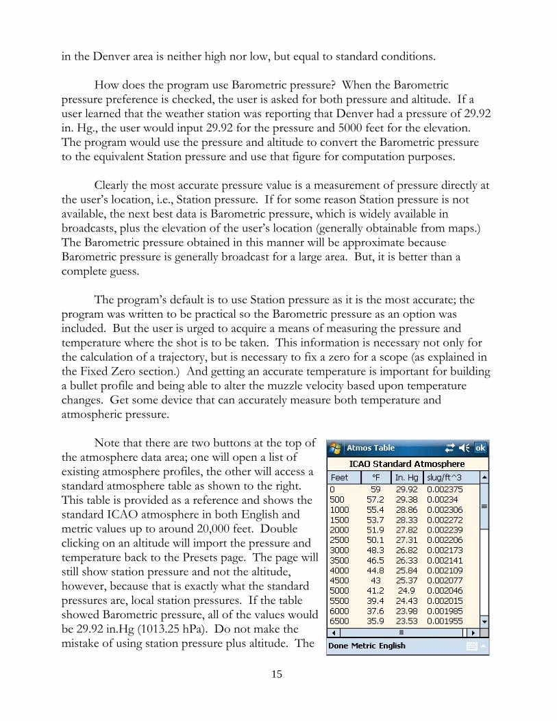
Note that there are two buttons at the top ofthe atmosphere data area; one will open a list ofexisting atmosphere profiles, the other will access astandard atmosphere table as shown to the right. This table is provided as a reference and shows thestandard ICAO atmosphere in both English andmetric values up to around 20,000 feet. Doubleclicking on an altitude will import the pressure andtemperature back to the Presets page. The page willstill show station pressure and not the altitude,however, because that is exactly what the standardpressures are, local station pressures. If the tableshowed Barometric pressure, all of the values wouldbe 29.92 in.Hg (1013.25 hPa). Do not make themistake of using station pressure plus altitude. The
15

resulting air density will be very low and the trajectories will look very flat.
Density AltitudeLooking again at the Presets graphic above, note that right above the Pressure
input window is a “read only” window labeled “D.A.”, or “Density Altitude”. Densityaltitude is a single number that reflects the density of air based on its pressure,temperature and humidity and provides the equivalent altitude of air with that densityas defined by the International Standard Atmosphere (ISA). The standard atmospherecharts shown in the preceding section are nothing more than a reflection of ISAatmospheres at the various elevations shown. Each altitude has a standard pressureand temperature and results in a defined air density for that altitude.
When the Station Pressure option is checked, the Density Altitude window willshow the equivalent density altitude for the variables of pressure, temperature andhumidity listed below it. This, in turn, will help the shooter understand how the airdensity is changing as conditions change and may help explain how bullet performanceis being affected for the given conditions.
Because density altitude is a reflection of air density, it can be a handy singlenumber data point to help a shooter judge what to expect for a trajectory for his givencartridge. While explaining how to use density altitude charts is beyond the scope ofthis manual, the user is encouraged to print out some density altitude charts (ElevationTable->Capture->Den.Alt.Table) for a given bullet profile, print out the densityaltitude charts (on the SD card in the \Documents folder) and use them as backup inthe event of a PDA failure.
[Note: When using a Kestrel connected to the program, do not expect theDensity Altitude as calculated by the Kestrel unit to agree with the program’scalculation. The problem is that the Kestrel does not send the actual pressure,temperature and humidity to the program; rather, it sends rounded off values. Forexample, when the program calculates the pressure at sea level, it calculates it as29.92115526565 in. Hg. and then rounds the value for presentation to 29.92. The useof rounded figure will result in a slight error in density altitude. When using theKestrel, pressure is rounded to two significant digits, temperature and humidity valuesare rounded to one significant digit, and then these values are sent to the program. The program will use the rounded values, but the resulting density altitude calculationwill not match that of the Kestrel which is using values of greater precision internally.]
16

Mils and MOA
Immediately below the Elevation and Windage buttons are the main outputwindows for the firing solution. The solution will be given in terms of Mils or MOAdepending upon user preferences. When the user chooses Mils as the basic unit forexpressing elevation and windage data, all solution windows are displayed in terms ofMils. This makes sense if the user has a “coordinated” scope setup, i.e., where theturret scale matches the reticle scale. If both are the same then it is appropriate for thesolution to have common units of measure. So, if the user has a Mil-dot reticle and aMil turret, he will prefer that the firing solution be given in terms of Mil units. Conversely, if the user has an MOA turret and an MOA reticle, he will prefer solutionsgiven in MOA units.
What about the “uncoordinated scope”? It is not uncommon, at least in theUnited States, for users to have a Mil-dot reticle paired with MOA turrets. With thisscope setup the user will want the firing solution to be in terms of MOA units but willwant the Lead for a moving target to be given in terms of Mils since he will be usinghis Mil reticle for all hold offs. To accomplish this setup, choose “MOA units” fromthe Options list and then press the Lead button to toggle between MOA and Mil units. Once the user has selected these options they will remain in that state thereafter untilchanged by the user. The program will “remember” these settings between uses. Inaddition, these preferences will be reflected in the Elevation and Windage tables. Essentially, the Lead units tell the program what type of reticle is being used and reticlerelated measurements will be output in those units.
Positive Click Values
The turret elevation solution in general produces a result in the form [turret #]“+” or “-“ [offset clicks]. Consider a Mil turret with 0.1 Mil click values. An elevation solution of 4.8 Mils can be expressed either as 4 + 8 or 5 - 2. Both are equivalent. Some users prefer to see only positive click values and selecting this option will insurethat all turret solution will show positive click values. In terms of the above example,the program would normally show 5 - 2 but with option selected the solution wouldshow the positive click equivalent, 4 + 8. See the further discussion of this topic in the“The Turret Profile” section below.
17

Elevation Solution Significant Digits
To the immediate left of the elevation solution window is a small unlabeledbutton whose function is to toggle between the one and two significant digits of theelevation solution. The reason for this option is that some shooters want the elevationsolution to be expressed with one significant digit so that the Mil solution can bedirectly interpreted as a turret setting. For example, a solution of 8.1 Mils is directlyunderstood as dialing to the number “8” on the turret plus one tenth of a Mil, onemore click. (Of course this only works if the turret click value is a true 0.1 Mil perclick.) Other shooters want to see the amount rounded so that they can “favor” eitherhigh or low depending upon the value rounded. If, for example, the actual solutionwas 8.06, the nearest value is rounded up to 8.1 which means that the shooter will dialslightly more than needed and can “favor low”. If, however, the 8.1 was roundeddown from 8.14, the shooter would favor high due to the fact that the solution wasactually a little more than was dialed.
Working with the Uncoordinated Scope
For historical reasons, many shooters have scopes that have MOA turrets but aMil reticle. This uncoordinated arrangement creates certain challenges for appropriatedata display: whether the shooter is going to dial or hold the wind dictates whether thewind solution should be displayed in MOA or Mil units. The situation becomesslightly more complex when the target is moving. Will the shooter dial the wind andhold a lead or should both the wind and lead be held in which case the shooter maywant a resultant hold off value that comprises the net hold after combining both windand lead?
The program attacks the problem by first allowing the user to toggle the Leadunits between Mil and MOA. Whichever is selected is deemed to be the units of thereticle. Upon selecting Lead units different from the Windage units, a units togglebutton for Windage also appears thus allowing the user to 1) keep the units suitable fordialing the wind; or, 2) change the units to those of the reticle so that windage may beheld. This solution works fine if the target is stationary. But when the target is movingand a cross wind is present, both the Windage and Lead will have hold off values. Again, two choices present themselves: 1) dial the wind and hold the lead; or, 2)combine both wind and lead values for a net hold off value. The user can either do themath mentally or choose the “Hold Off” option which converts the Lead button anddata window to a “Hold Off” function and displays the net hold off value therebyaccounting for both the wind and lead corrections. Where target speed is zero, thehold off window can be used to display only the wind hold off value.
18

Getting Started - The Basics
To use this program it is not necessary to build profiles or use any of the othertools which are provided. To compute a trajectory and to obtain the necessaryelevation and windage, the user need only input five sets of data and access only twopages of the program - the main page and the presets page. On the Presets page (clickon “Presets” on the Main page menu) enter the following:
1. Atmospheric data consisting of the local station pressure (or theBarometric pressure and an altitude - see Station versus BarometricPressure in the User Preferences section), the current temperature and thehumidity. The humidity has only a tiny impact on atmosphere density soif the humidity isn’t known, use 50% and call it good. The temperatureand pressure, however, have definite impacts upon the local density ofthe air which has a consequent impact upon the resistence the bullet willexperience as it travels its trajectory to the target. It is important thatthese values be as accurate as possible.
2. Bullet data consisting of the muzzle velocity (on the importance ofobtaining a good and accurate muzzle velocity see the Preparationsection, Muzzle Velocity), bullet weight, bullet ballistic coefficient. Leavethe DK set at the default of 0.5 until a custom DK has been computed. (This is explained in the Using the Refinements section.) The muzzlevelocity must be measured by the shooter; a manufacturer’s publishedmuzzle velocity is not sufficient. However, the manufacturer’s publishedbullet weight and ballistic coefficient is sufficient at least at the beginning. Just ensure that the ballistic coefficient is based upon the G1 dragfunction. Almost all, if not all, bullet manufacturers use the G1 ballisticcoefficient so if it doesn’t state to the contrary, the published ballisticcoefficient most probably is G1 based. (Later the user will want tocalculate his own ballistic coefficient using the tools provided in theprogram. In the meantime, don’t be afraid to vary the ballistic coefficientif doing so improves the predictive ability of the program. Manufacturersusing optimistic ballistic coefficient figures are not an unheard ofphenomenon and in any case, the drag function on which theircalculations are based is undoubtedly not the drag function used in thisprogram.)
3. Scope data consisting of the scope height above the centerline of the boreand the range at which the scope is zeroed. To get the scope height, finda centrally located place on the scope and measure from the center line ofthe scope tube straight down to the centerline of the bore. It is not
19
necessary to a two decimal point precision measurement; a measurementto the nearest tenth inch is more than sufficient.
The foregoing data will not change (or will change slowly in the case oftemperature and pressure) and generally can be left alone unless the shooting sessionlasts more than a couple of hours. In that case it’s best to recheck pressure andtemperature and modify the data as necessary. (Note that the presets page alsocontains Atmosphere, Bullet and Scope buttons to access the profiles of the samenames. The topic of profiles is taken up in the Support Tools section.)
After entry of the Preset data, tap “Accept” and move back to the main page. Once there, enter:
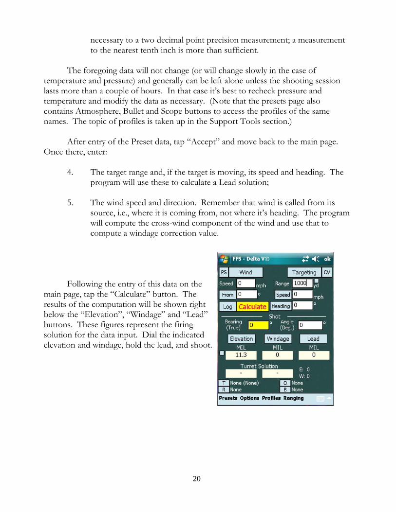
4. The target range and, if the target is moving, its speed and heading. Theprogram will use these to calculate a Lead solution;
5. The wind speed and direction. Remember that wind is called from itssource, i.e., where it is coming from, not where it’s heading. The programwill compute the cross-wind component of the wind and use that tocompute a windage correction value.
Following the entry of this data on themain page, tap the “Calculate” button. Theresults of the computation will be shown rightbelow the “Elevation”, “Windage” and “Lead”buttons. These figures represent the firingsolution for the data input. Dial the indicatedelevation and windage, hold the lead, and shoot.
20

Using the Refinements
There are several tools added to the program to help refine the calculated firingsolution. They are presented here in no particular order.
Wind Zones
Immediately above the wind speed input window is a “Wind” button. Pressingthis button takes the user to a wind zones page where the user can specify up to threeseparate wind zones that may appear across a course of fire. The purpose of this pageis to handle the not so uncommon experience of observing what appears to be windblowing in two (or even, less commonly, three) directions at the same time.
Check the box for up to three zones, then input the ending range for each zone,the wind speed and wind direction for that zone. Then move to the next zone andinput the data pertaining to that zone. When finished, the range should start with 0 inzone one and then finish at the target range for the last zone.
Example: assume that the user is shooting ata target 931 yards away and observes that from hisfiring position and out for 420 yards wind isblowing in at 270 degrees at 2 mph but then seemsto shift and from that point to the target the windappears to come from 195 degrees at 3 mph in thenext zone out to 700 yards and then shifts again to4 mph from 125 degrees to the target. The setupof the wind zones would look like the image to theright. When the user hits “Accept”, the data istransmitted back to the main page but becausethere is no place to put multiple wind vectors, thewind boxes show a “resultant wind vector”, asingle equivalent value for the total right or leftdeflection. As a visual cue that multiple windzones are in effect, the Wind button will go dark incolor. Any attempt to change the wind values, usea Kestrel to update conditions, update the Target Range Card, or select a differenttarget will cause the multiple zone mode to terminate.
[Note: It is possible to actually track the course of the bullet as it deals with thisshift in the wind. From the main page, click the “Elevation” button and look at the farleft “Wind” column. This column shows the position of the bullet in terms of MOA
21

or Mils with respect to the range and it is possible to see the movement of the bulletfirst to the right due to the left wind then slowing in its rightward movement as thewind begins to come from the right. By changing values and direction it is possible tosee a right drifting bullet to slow, stop and begin to move leftward. [As for the neverending argument as to which wind affects the bullet the most, that at the muzzle orthat at the target, experiment with the program and see for yourself.]
There is also a Wind Speed Calculator shown on this page, but this tool will bediscussed in the Support Tools section. See Wind Speed at Range.
Spin Drift
Spin drift is the movement of the bullet that occurs as a result of the fact that itis spinning about the longitudinal axis and is being subjected to gyroscopic forcesresulting from its spin and the aerodynamic forces acting upon it due to the rush of airmoving past it. Various and sundry forces arise from these circumstances, but forpurposes of this manual let it suffice to say that when the bullet stabilizes in flight afterleaving the barrel, its longitudinal axis does not point exactly forward. For clockwisespinning bullets, the bullet comes to a point of equilibrium with its longitudinal axispointed slightly to the right. In other words, the longitudinal axis of the bullet is notexactly tracking the trajectory; the axis is slightly rotated to the right and the relativewind is striking the bullet slightly more on the left side, pushing the bullet to the right,as the bullet goes downrange. The result of this is what appears to be a drift of thebullet to the right.
While spin drift occurs for all bullets at all ranges, below 500 yards it is relativelya minor measurement and basically ignored. At longer ranges, however, it should notbe ignored. A .308 Winchester with a 175 gr. SMK shot at around 2635 fps muzzlevelocity will experience spin drift of around 10 inches at 1000 yards. This is nearly onefull MOA and obviously significant enough to correct for. The FFS program has theability to automatically correct for spin drift. On the Options menu, click on SpinDrift and the calculated spin drift will become part of the windage solution. You cancheck the amount of drift by selecting and then de-selecting Spin Drift and seeing thechange in windage.
Irrespective of the range the user intends to shot, there really isn’t a reason notto select Spin Drift and leave it selected. At worst, it will have no real impact on thecalculations; at best it will keep the user from missing the target.
Rule of Thumb for Spin DriftIn the absence of having the computer handy, is there a fast, “down-and-dirty”
22
way to approximate spin drift? There is. Because spin drift is present in all shots andalways is in the same direction for a given barrel twist, it is possible to approximate theamount of drift by assuming a 1 mph cross-wind from 270º (for a right twist barrel). Example: assume wind is 4 mph from 90º to the shooter. Knowing that spin drift hasthe effect of a 1 mph cross-wind from the left, the net wind is 3 mph from the rightand that is the figure the shooter should use to calculate windage. In the reversesituation, if the wind was coming directly from the left at 4 mph, the shooter wouldadd an additional 1 mph and compute the windage for a 5 mph cross-wind. It won’tbe exact, but it will be close.
Powder Temperature
A change in the ambient temperature changes the trajectory of a bullet in twoways: first, a temperature change affects the air density which directly affects the abilityof the bullet to move through the air. As the temperature rises, the air become lessdense and the bullet will tend to experience less drop over the same range because it isbleeding off its speed at a slower rate. The reverse is also true: a drop in temperaturecauses the atmosphere to grow more dense, slowing the bullet faster, requiring moretime to traverse the same range thereby causing the bullet drop to increase. Bullets willtend to strike the target lower as the air becomes more dense. This direct effect of achanging temperature is handled by the program as part of the way it computes airdensity from the atmospheric data on the Presets page.
But there can also be an indirect effect of changing temperature. When thetemperature drops, powder temperature can also drop, barrel temperature drops and asa consequence of this muzzle velocity drops as well. The reverse tends to be true aswell: as temperatures increase, powder temperatures increase, barrel temperaturesincrease and bullet muzzle velocity tends to increase.
Not all powders behave the same way in this regard and some powders seem tobe affected much more that others as a result of temperature fluctuations.6 In order to
6 The operative word here is “seems”. Hodgdon publishes data showing that its “Extreme”brand of powders are very insensitive to changes of temperature. However, the testing methodologyis not published. There is at least one article, written by Denton Bramwell in 2003, “PressureFactors: How Temperature, Powder, and Primer Affect Pressure”, that suggests that possibly risingbarrel temperature, and not rising powder temperature, is responsible for increased muzzle velocity. Powder temperature may be irrelevant or at least not significant. Find and read the article. There iscontrary data, however. Sgt. Glen Roberts, a police sniper team leader who works for the WesternAustralia Police and very careful student of exterior ballistics, has collected interesting experimentaldata indicating that changing barrel and receiver temperatures does not affect muzzle velocity, butthat changing powder temperature does. Clearly, more work in this area is warranted.
23

deal with this indirect effect of temperature change, an option was included that allowsthe user to indicate what change of velocity occurs for the powder he uses per degreechange of temperature. This requires that the user 1) know what the ambienttemperature was when he obtained the muzzle velocity data for his particular load; 2)make some attempt through experimentation to discern how the powder he uses reactsto temperature changes; and 3) know the current temperature of the powder or at leastthe surrounding air. All of this data can be input by hand, but is more convenientlystored in a Bullet Profile (discussed in the Profile section of the manual). Uponloading this profile, the program will have the data it needs to modify the muzzlevelocity of the cartridge as different atmospheric temperatures are input by the user.
Once the “Powder Temperature” option is checked, the program will assumethat the powder temperature is that as recorded in the bullet profile. Or, if the user isexperimenting with powder temperatures, the user can keep the powder at a particulartemperature and specify that powder temperature irrespective of what the airtemperature is. This option is located on the Presets page and is associated with theBullet data items. Note that when the “Powder Temperature” option is active, the“Powder Temperature” window on the Presets page becomes active and writable.
As an alternative to specifying a powder temperature, the user can simply havethe program assume that the powder temperature is the same as the ambient air andmake its calculations accordingly. This is done by checking the “Ambient PowderTemperature” box. The user is also free to specify the change in velocity per degreetemperature change. As can be seen, while all of the data is conveniently placed in thebullet profile, it is still possible to input all the data by hand. The recommendation is,however, to learn how to create a bullet profile and use that method of storingcartridge data.
As a final note, given Mr. Bramwell’s article as noted in the above footnote andhis suggestion that perhaps all powders are relatively temperature insensitive but thatbarrel temperature actually dictates changes in muzzle velocity, it is possible that thisoption has been misnamed and should actually be called “Barrel Temperature”. However, as a practical matter it hardly matters. A barrel that has been unfired for atime assumes ambient air temperature. A barrel that is hot transmits that heat to thepowder in a fairly short amount of time while the cartridge is sitting in the chamber. We know that hot barrels generally result in higher muzzle velocities, but it would bevery difficult to monitor barrel temperature on a shot by shot basis then input thetemperature changes into the program in order to change the muzzle velocity. The“Powder Temperature” option is a “refinement” and attempts to make animprovement on the data that is fed to the trajectory calculating engine. On a practicalbasis, using air temperature and some rate of change metric to vary the muzzle velocitywill give an approximation of what is happening to muzzle velocity. It is, in all
24
respects, better than doing nothing at all.
Vertical Deflection
Everyone knows that a cross-wind causes a horizontal deflection of the bullet inthe direction that the wind is blowing. It is less commonly known that a cross-windalso causes the bullet to be vertically deflected as well.
The reason why the bullet experiences a vertical deflection in a cross-wind hasto do with the fact that as the bullet exits the muzzle, within a very short distance,small enough to be measured in few calibers, the bullet noses into the wind. Thismovement of a rotating body is accompanied by either a dipping or rising of the noseof the bullet until the bullet reaches a state of equilibrium with the various forces actingupon it and results in what is called “aerodynamic jump”7. This momentary dipping orrising alters the path of the bullet slightly either slightly uphill or slightly downhill. Fora clockwise spinning bullet, a cross-wind blowing from the left will cause the bullet todip; a cross-wind coming from the right will cause the bullet’s tip to lift slightly as itnoses into it. The result is that down range, the bullet strikes will tend to impactdownward and to the right in a left wind and upward and to the left in a right windalong a line intersecting the center of the target and through the 10 and 4 o’clockpositions approximately. The movement is relatively small in light winds (6 mph orless) but in heavy winds (10 mph and above) the vertical deflection can becomesignificant which is why it was included.
Coriolis Acceleration/Eötvös Effect
The movement of the bullet due to Coriolis acceleration is an apparent horizontalmovement that results from the fact that due to the earths rotation the apparent pathof the projectile will seem to curve . In the Northern Hemisphere the curve is to theright; in the Southern Hemisphere the curve is left. In addition, shooting East or Westcauses the bullet to strike the target higher or lower respectively a phenomenon knownas the Eötvös effect.8
7 For more information on this phenomenon, see McCoy, “Modern Exterior Ballistics”(1999), at section 12.9, page 267.
8 Although commonly referred to as one effect, the vertical deflection in shooting East or West isn’t actually part of the Coriolis effect, but is a consequence of shooting on a rotating (Cont.)body. More properly called the Eötvös effect, it is caused by the apparent reduction or increase inthe force of gravity as felt by the bullet due to centripetal force. When the Coriolis effect option ischosen, the program also computes and applies both the Coriolis and Eötvös effects to the
25

In small arms, the Coriolis/Eötvös effects are generally ignored. It is basically atime dependent issue and since small arms projectiles are actually in the air no morethat 3 to five seconds for extremely long ranges, the amount of target movement issmall. Small, however, is not inconsequential. A .308 Winchester shooting a 175 gr.SMK with a muzzle velocity of 2635 fps will have a flight time of nearly 1.8 seconds to1000 yards and the Coriolis effect will produce an apparent movement of the bullet ofabout 3 inches in the mid latitudes. Now, 3 inches at 1000 yards is not a great error. On the other hand, it is over 1/4 MOA and is easily correctable with one click of thewindage knob. Eötvös effect is similar in terms of degree of magnitude.
The downside to computing a Coriolis/Eötvös error is that the shooter mustknow his latitude due to the fact that this apparent movement of the bullet is directlyinfluenced by where on the planet the shot is being taken. And he must know his shotbearing to get a complete solution since the bearing will determine the amount ofapparent rise or fall of the bullet relative to the target. For this version of the software,this should not be an issue. The software has so many tools that deal with the shooterslocation that the software expects that the coordinates of the shooting location will beinput. And if the user has a GPS that connects to the PDA, getting and inputting thecurrent location is simple. (This topic is fully explained in the GPS, Map andRangefinder Ranging sections of the Support Tools chapter.)
Furthermore, while shooters may argue about the need for a Coriolis/Eötvöscomputation, if the shooter is using software to compute a firing solution, there is noreason not to include the calculation as a refinement. It costs nothing and can onlyadd to the precision of the solution. Having said that, if a shooter did not have accessto a ballistics computer and was computing a firing solution manually, there is littlequestion that the time it would take to include a Coriolis/Eötvös calculation would notbe justified. No matter where on earth the shot is taken, the Coriolis/Eötvöscomponents are going to be small and either effect could be zero. In the absence of anautomated computing device, there would be no reason to dwell on the subject and theeffect should be ignored.
Calculating a DK
Most ballistic programs use the same information to calculate a ballistic solution. Once the data is input and the “Calculate” button is pushed, the program churns outan elevation in terms of an angle measurement, conventionally as an MOA or Milvalue. The problem is that the point at which the bullet may strike the target isdependent upon more that the bullet, scope, atmosphere and range data the user
trajectory.
26

provides. In particular, the mechanics of the bullet ignition, barrel vibration andshooter interaction with the rifle during recoil all affect and influence the point ofimpact. That is why it is a fortunate shooter who can buy ballistic software and findthat it is dead-on accurate. How could the software anticipate how that particularshooter managed his rifle? How did the software accommodate the varied mechanicalaspects of the rifle from ignition to the bullet exiting the muzzle? The short answer isthat it doesn’t and didn’t. As a mind problem, consider two trained snipers and oneM40A3 rifle shooting good M118LR ammunition. The proper elevation for a 1000yard shot is dialed and each sniper shoots five rounds. The rifle is cleaned and allowedto cool before the second sniper fires his five rounds. Same rifle, same scope, same lotof ammunition. What are the chances that the two five round groups will be located inslightly different places? The chances are actually quite good because even thougheach sniper received similar training, the exact movement of the rifle during theignition and explosive phases of the bullet launch will not be the same; the rifle/bodyinterface is not the same from individual to individual and each person sees the imageproduced by the scope slightly differently. These differences can and will causedifferences in the precise location of the barrel when the bullet exits whichconsequently will cause the bullets to impact in a slightly different location on thetarget. That is why snipers take extensive notes to record how their individual rifleshoots in a variety of conditions and why the previous user of the rifle cannot just passon his log book. The data for one sniper will not necessarily fit or be useful to anothersniper, even though each is shooting the same identical rifle.
How to deal with this? The answer is to create a way to “customize” thetrajectory to enable the user to get the program and his actual experience on the rangeto match - meaning that if it takes 38.3 MOA for shooter A to get the rounds to hit inthe center of the target at 1000 yards, he would like a way to get the computer topredict an elevation of 38.3 MOA for that range. If shooter B shooting his rifle takes37.8, he wants the computer to predict 37.8 for the elevation. To accommodate bothshooters, the software has a constant, the DK value, which will alter the point ofimpact of the bullet without changing the other calculated parameters such as drop,path, time of flight, etc.. In essence, the trajectory will be customized for the individualshooter.
In order to customize the trajectory for the user of this software it is firstnecessary that the user follow the Preparation section of this manual. He absolutelymust calibrate his scope, obtain a highly accurate muzzle velocity for the specificcartridge he is using, calculate the bullet’s ballistic coefficient, and accurately measureand record the atmospheric pressure and temperature that existed at the time of thetesting that will be described below. Only after the preparatory work is done does itmake any sense to attend to customizing the DK. However, once a DK is found, thatDK is good for that rifle, cartridge and shooter thereafter, assuming that the user
27
doesn’t alter his shooting style or make changes to his rifle system. If he does, it is bestto take the steps necessary to re-establish a DK. Until these steps are taken, the usercan and should use the default DK of 0.5. It is amazing how well the default valueworks for a variety of bullet calibers and weights.
Gathering the DataThe idea behind the DK calculation is to find out the actual drop of the bullet at
sufficient range. Given that most of us don’t own a backyard Doppler radar, the onlypractical way we can know how much a bullet drops is to measure the drop by meansof the scope turret. Whatever the user must dial to reach a distant target is the angleequivalent of the bullet drop at range. That is why it is so important to calibrate thescope so that the drop measurement is accurate.
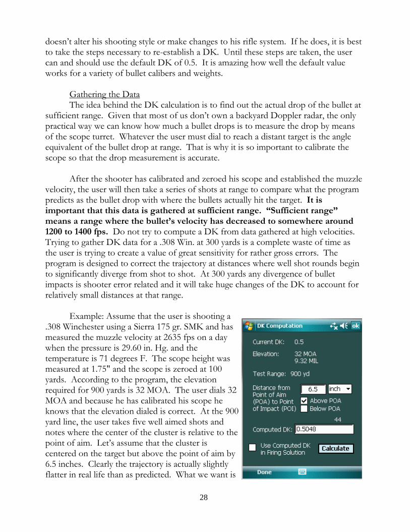
After the shooter has calibrated and zeroed his scope and established the muzzlevelocity, the user will then take a series of shots at range to compare what the programpredicts as the bullet drop with where the bullets actually hit the target. It isimportant that this data is gathered at sufficient range. “Sufficient range”means a range where the bullet’s velocity has decreased to somewhere around1200 to 1400 fps. Do not try to compute a DK from data gathered at high velocities. Trying to gather DK data for a .308 Win. at 300 yards is a complete waste of time asthe user is trying to create a value of great sensitivity for rather gross errors. Theprogram is designed to correct the trajectory at distances where well shot rounds beginto significantly diverge from shot to shot. At 300 yards any divergence of bulletimpacts is shooter error related and it will take huge changes of the DK to account forrelatively small distances at that range.
Example: Assume that the user is shooting a.308 Winchester using a Sierra 175 gr. SMK and hasmeasured the muzzle velocity at 2635 fps on a daywhen the pressure is 29.60 in. Hg. and thetemperature is 71 degrees F. The scope height wasmeasured at 1.75" and the scope is zeroed at 100yards. According to the program, the elevationrequired for 900 yards is 32 MOA. The user dials 32MOA and because he has calibrated his scope heknows that the elevation dialed is correct. At the 900yard line, the user takes five well aimed shots andnotes where the center of the cluster is relative to thepoint of aim. Let’s assume that the cluster iscentered on the target but above the point of aim by6.5 inches. Clearly the trajectory is actually slightlyflatter in real life than as predicted. What we want is
28

the program to predict an impact point 6.5" higher. Having gathered the data, we canuse the “Calculate DK” located on the Options menu. The user merely indicates thedistance and direction of the group from the point of aim and taps the “Calculate” key. The program will go into a iterative loop where it changes the DK slowly until thecorrect elevation is computed for the input conditions. As shown by this example, thehigher the DK, the flatter the trajectory, rather like the ballistic coefficient. The userwill take this DK and input it into the bullet profile which he has created for thisparticular round and the trajectories computed will be customized to his shooting.
There is a subtle potential error in this calculation that the reader may haveperceived. When the user dials in the firing solution, he can only dial in whole clicks. If the elevation is calculated at 32.2 MOA, for example, the turret output will be to thenearest whole click value, or 32 MOA assuming a 1 MOA per click turret. This meansthat when a shooter dials an elevation solution he can only get within plus or minus aone-half click value with his turret. The implication of this is that if bullet impacts arewithin one-half of the click value above or below the point of aim, no furthercorrection is necessary as a practical matter. The program anticipates this problem andactually calculates the turret error, compensates for it, then calculates the actualdistance from the POA the bullet strikes were and then calculates the DK. Therefore,irrespective of the turret error and how close the point of impact is to the point of aim,the program will calculate an accurate DK. The point here is only that any firingsolution is only as close as the turret click values permit. A 1 MOA per click scopedoes not get any more precise because the user calculates a DK out to 5 decimalpoints. And the resulting firing solution can only be implemented by the scope plus orminus one-half of its click value. So, don’t get carried away with computations thathave no real meaning or application given the equipment available.
Having all the above statements in mind, remember that there are other reasonswhy the 6.5 inch error arose including the possibility that the derived muzzle velocitywas off by a few feet per second, or the calculated ballistic coefficient was slightly off,or there was a slight undetected updraft on the range that day. Be reluctant to changethe default DK and do so only after all other factors have been resolved andconsidered.
29

Support Tools
There are a number of tools offered in the software to help in various ways tosupport a cold clean bore, first round hit at range and to thereafter aid the user inrapidly engaging multiple targets. Where possible, useful data is pre-packaged in filescalled “profiles”; tables are provided to organize target acquisition, elevation andwindage data; data for each individual shot can be logged; timers are offered to helpcompute the speed of objects, people or wind at distance. This chapter will explore indetail each support tool offered.
The Target Range Card
Clicking on the “Targeting” button at the top of the main page brings up theTarget Range Card, probably the most powerful and meaningful display of data in theprogram, outside of the main page. This data presentation combines the functionalityof the Target List, Elevation Table, Windage Table, Map, Direct, GPS, and LaserRanging functions, into a single location to rapidly create and catalog multiple targetsfrom a single firing position, presenting the firing solution data in the form of elevationhold-offs and relative windage values for each target such that the shooter can rapidlyacquire any of the listed targets without dialing the firing solution. Second, the createdtarget list can be edited, modified, and saved as individual targets and, moreappropriately, a target group all from this work area. In addition, each of the individualtargets created, as well as the related FFP, is also accessible from the Target List andare editable in the various locations in the program for editing target and FFP profiles.
Review of Target File TypesThe program allows for the creation of two types of target related files: the
“Direct” ranging file and the “Position” or “Location” file. The direct ranging file is asimple file as it merely comprises a range, bearing and angle. It is not connected to anyparticular location on Earth and is compatible with any loaded FFP. This type of file isincluded in the program to enable the creation of target files in circumstances wherethe current FFP coordinates are not known. In the absence of FFP coordinates, it isnot possible to calculate target coordinates and therefore it is not possible to createlocation or position target files. These simple range only files can be loaded under anycircumstance since doing so only means the loading of a range, bearing and angle tothe main page of the software.
The second type of file is the “Position” or “Location” file; it consists of thelatitude, longitude and altitude of a specific location on Earth. In order to use aposition file it is necessary to pair the target position with a shooting position, an FFPfile which contains the latitude, longitude and altitude of a firing position. Once the
30
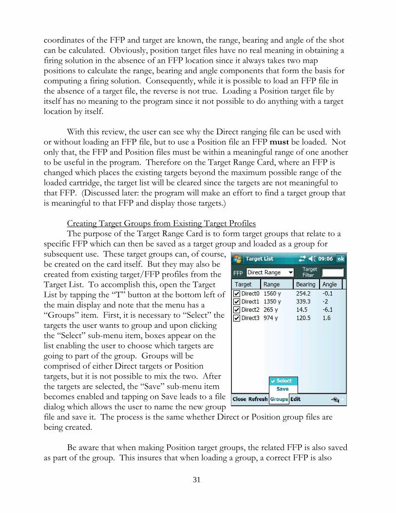
coordinates of the FFP and target are known, the range, bearing and angle of the shotcan be calculated. Obviously, position target files have no real meaning in obtaining afiring solution in the absence of an FFP location since it always takes two mappositions to calculate the range, bearing and angle components that form the basis forcomputing a firing solution. Consequently, while it is possible to load an FFP file inthe absence of a target file, the reverse is not true. Loading a Position target file byitself has no meaning to the program since it not possible to do anything with a targetlocation by itself.
With this review, the user can see why the Direct ranging file can be used withor without loading an FFP file, but to use a Position file an FFP must be loaded. Notonly that, the FFP and Position files must be within a meaningful range of one anotherto be useful in the program. Therefore on the Target Range Card, where an FFP ischanged which places the existing targets beyond the maximum possible range of theloaded cartridge, the target list will be cleared since the targets are not meaningful tothat FFP. (Discussed later: the program will make an effort to find a target group thatis meaningful to that FFP and display those targets.)
Creating Target Groups from Existing Target ProfilesThe purpose of the Target Range Card is to form target groups that relate to a
specific FFP which can then be saved as a target group and loaded as a group forsubsequent use. These target groups can, of course,be created on the card itself. But they may also becreated from existing target/FFP profiles from theTarget List. To accomplish this, open the TargetList by tapping the “T” button at the bottom left ofthe main display and note that the menu has a“Groups” item. First, it is necessary to “Select” thetargets the user wants to group and upon clickingthe “Select” sub-menu item, boxes appear on thelist enabling the user to choose which targets aregoing to part of the group. Groups will becomprised of either Direct targets or Positiontargets, but it is not possible to mix the two. Afterthe targets are selected, the “Save” sub-menu itembecomes enabled and tapping on Save leads to a filedialog which allows the user to name the new groupfile and save it. The process is the same whether Direct or Position group files arebeing created.
Be aware that when making Position target groups, the related FFP is also savedas part of the group. This insures that when loading a group, a correct FFP is also
31

loaded. However, it is possible to include a target in more than one group. The onlylimitation is that the target must be within the maximum possible range of a givencartridge from the associated FFP. If the user attempts to create a group file and toadd a target beyond this distance, the attempt will be ignored and the file will not beadded. The program will assume that the user simply made a mistake and refuse toinclude the target in with the group.
Looking at the list of position targets on the list, thefilter has been removed so that the ranges fromAlpha to all of the targets is shown. Note that therange from Alpha to some of the other targets isdeemed “Futile” by the program because thesetargets are beyond the maximum possible range ofthe cartridge that is currently loaded; there is noreason why the program should compute an actualrange for these targets and therefore doesn’t.
Now look at the target lists for Bravo andCharlie FFPs, again with the filter removed. Charlieis an FFP that is a short distance from Bravo sotargets associated with Bravo and Charlie may beaccessed from either FFP. And, it would be possiblefor the user to create target groups
which included any of those targets in a Bravo and/or Charlie group file. Fordemonstration purposes, the program comes with Alpha, Bravo and Charlie groupfiles. Alpha contains targets A-1 through A-4; Bravo, B-1 through B-3 and Charliecontains B-2, B-3, and C-1.
As a naming convention for Position target groups, it is helpful if the group fileis named after the FFP. The reason why is, as will be seen in the discussion of the
32

functioning of the Target Range Card itself, when FFPs are changed, the programsearches for a target group with the name of the FFP and loads it assuming that theuser will want targets shown that are within range of the selected FFP.
Using the Target Range CardTapping the “Targeting” button on the main program page brings up the Target
Range Card. If the user has created group files, each group file will be listed in thedrop-down “Target Groups” list. Tapping on one of the group files will load the fileinto the list view area. Group files may consist of either Direct or Position targets. Asalready mentioned, the Position groups contain not only target positions but therelated FFP as well. When loading a group of Direct target files, therefore, no changeis made to the current FFP, even if that is “None”. However, when loading a group oftarget position files, the FFP is also loaded to that FFP that is contained in the file.
A. Loading a group fileThe program comes with four group files:
Direct, Alpha, Bravo and Charlie. A group file isloaded by dropping the Target Groups list andtapping on one of the available groups in the list. The graphic shows the list and what the form wouldlook like with Alpha loaded. Note at the top of theform the FFP is shown as Alpha and targets A-1through A-4 are displayed on the list view. Thesetargets were added to the group file in the Target Listas explained above. Note also that the name of theform at the very top has changed to the name of the
group file in orderto help the userknow at any timewhat file is loaded,particularly if the file name is not that of the FFP.
An FFP may be changed in much the sameway except the catalog of available FFPs are in the“FFP Files” drop-down list. In this case, there arethree FFP files: Alpha, Bravo and Charlie. TheFFP list shows those three. If an FFP is selectedwhich is in conflict with the listed targets, that is ifthe FFP is mismatched to the targets and theresulting distances between the two exceed themaximum possible range of the loaded cartridge,the targets are removed from the list and the
33

program tries on its own to find a group file containing suitable targets. Show in thegraphic is the consequence of selecting the Bravo FFP. Note the change of name atthe very top and the change of FFP. When the FFP Bravo was selected, the programwent through the available group files to determine whether there was one named afterthis FFP and upon finding one, opened it and loaded the files it found.
B. What is “Reference Data”?When the Target Range Card is first invoked, the main page has certain
parameters set for wind speed, wind direction, shot bearing, range to target, and therequired elevation needed for that target at that range. These are the initial “referencedata” and are used to compute relative windage values and vertical holds for the loadedtargets. In other words, if wind direction is from the immediate left (270 degrees or 9o’clock) for a target with a bearing of 330 degrees, when we change targets to one at 0degrees, the relative wind has now shifted to the rear 30 degrees, the same amount thatthe bearing changed to acquire the new target. Now the wind is coming from 240degrees relative to the shooter. If there are multiple targets each at a different bearing,obviously each target will have its own wind value since the wind relative to that targetwill coming from a different direction relative to the shooter and hence have adifferent windage correction. In order to make each of these calculations, it isnecessary to know in the first instance what the wind direction was relative to a specifictarget bearing, then as the bearing changes, the relative wind for the new bearing canbe computed and known.
Initially, the reference data will be taken from the main page. This may or maynot be helpful, but as mentioned reference data is required for the calculations that aremade in this page. Below are four graphics showing the initial main page settings, theresult of importing that data into the Target Range Card, the changes that result fromdesignating an FFP, and finally the result of designating one of the listed targets as thereference. Note, it is not necessary that an FFP be designated before loading a groupof targets. In this case, the designation was made to show the effects of suchdesignation to better understand what the form is doing and why.
First, the main form shows the wind speed anddirection, target range andtarget bearing. Although thebearing windows shows acompass bearing, because noFFP is loaded, the magneticvariation is 0 degrees, so thecompass and true bearings arethe same value. Note that on the Target Range
34
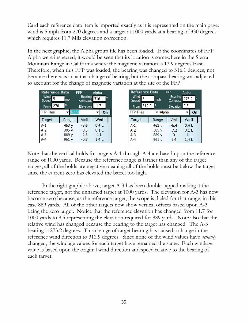
Card each reference data item is imported exactly as it is represented on the main page:wind is 5 mph from 270 degrees and a target at 1000 yards at a bearing of 330 degreeswhich requires 11.7 Mils elevation correction.
In the next graphic, the Alpha group file has been loaded. If the coordinates of FFPAlpha were inspected, it would be seen that its location is somewhere in the SierraMountain Range in California where the magnetic variation is 13.9 degrees East. Therefore, when this FFP was loaded, the bearing was changed to 316.1 degrees, notbecause there was an actual change of bearing, but the compass bearing was adjustedto account for the change of magnetic variation at the site of the FFP.
Note that the vertical holds for targets A-1 through A-4 are based upon the referencerange of 1000 yards. Because the reference range is farther than any of the targetranges, all of the holds are negative meaning all of the holds must be below the targetsince the current zero has elevated the barrel too high.
In the right graphic above, target A-3 has been double-tapped making it thereference target, not the unnamed target at 1000 yards. The elevation for A-3 has nowbecome zero because, as the reference target, the scope is dialed for that range, in thiscase 889 yards. All of the other targets now show vertical offsets based upon A-3being the zero target. Notice that the reference elevation has changed from 11.7 for1000 yards to 9.5 representing the elevation required for 889 yards. Note also that therelative wind has changed because the bearing to the target has changed. The A-3bearing is 273.2 degrees. This change of target bearing has caused a change in thereference wind direction to 312.9 degrees. Since none of the wind values have actuallychanged, the windage values for each target have remained the same. Each windagevalue is based upon the original wind direction and speed relative to the bearing ofeach target.
35

C. Changing Reference DataThe reference data can be easily changed by
simply changing the values in the text windowsand hitting the “Update” menu item. Changingwind conditions would require a change of thereference wind, so based upon the data as is shownin the above graphics, if it is assumed that targetA-3 is still the reference target but that the windhas changed from 312.9 degrees to 45 degrees andhas increased in speed to 7.5 mph, those valueswould be entered and then the program“Updated”. The result is shown. In this case,none of the options have been checked so there is no change in elevation, but thecross-wind component of the wind can result in a vertical deflection which wouldcause changes in the hold values as well.
D. Creating a Target CardIt is certainly probable that a group file for a shooting location will not exist
upon arrival to a firing position. The data, however, can be created with nothing morethan a GPS and range finder. For this example, it is assumed that the user has thesoftware deployed in a Trimble Nomad or similar hand held computer. Upon arrivalat the firing position, the GPS is activated from the software by going to Ranging->GPS and hitting the Start menu item. Data from the built-in GPS receiverimmediately begins to stream in and after a short while the data stabilizes and thehorizontal and vertical degree of precision (HDOP and VDOP) reach levels of 3 orbetter indicating that the data is sufficiently precise for use by the program. Looking atthe Target Range Card, the user sees a grayed out “GPS” item. When the GPS data issufficiently precise, the GPS function is enabled allowing the user to tap GPS and get acurrent fix. Immediately the user is prompted for a name for the FFP file that will besaved representing the current location and upon saving those coordinates are loadedinto the program as the working FFP and will be reflected at the top of the form.
The user has attached the range finder to the PDA via the DB9 connector, hasgone to Ranging->Rangefinder->[Range finder ID], opened the proper COM port andis ready to receive data from the range finder. Having established the current FFPcoordinates, he begins to range targets. Because with each ranging, the resulting datawill be transmitted to the Target Range Card in a separate line, he hits the “On” buttonto toggle it to “Off”. This prevents the data from being displayed on the page and isignored until such time as the user presses the button back to “On”. When the userhas surveyed the area and is ready to record targets, he taps the “On” button andbegins to range specific targets. Each is given a name starting with the first two lettersof the FFP followed by “TP” and a sequential number. The “TP”stands for Target
36

Position and is a reminder that the target files being created are position files, notDirect (range, bearing and angle) files. (It is possible to use the range finder to createDirect files when the coordinates of the FFP are unknown, in which case the files arenamed “RO” (range only) followed by a sequential number.)
At the conclusion of this work, the user has a TargetRange Card that looks like this. In this case, theFFP was called “Echo” and saved as such using the“Save” menu item. Note that upon saving, thegroup file is added to the Target Groups drop-downlist. Checking the Target List, the user will find thateach file, the FFP file and a group file called “Echo”has been added to the FFS_Targeting directory.
E. Editing and Saving the Target CardIndividual target files and FFP files can be
edited in this work area. The first editing functionto review is the “tap and hold” method of editing anindividual entry on the card list. Just tap and holdthe stylus on a target entry and then choose “Edit”. The result is shown. This edit feature is limited tochanging a name, range, bearing or angle of aparticular target. After the edit is completed, tap the “Done” button and the changes are reflected in thelist. Note, however, that any edit must be Saved tobecome a permanent change.
By tapping and holding in a clear area on the list, the context menu that emergesallows the user to add targets either by creating a target in the edit section as shownabove or by adding an existing file (discussed in depth below.) Again, the adding of anentry does not make the change permanent. The changes must be saved and if theuser leaves the Target Range Card form or tries to clear the form without saving thechanges, he is prompted to save the data at that time.
The second and more extensive way to save the FFP and target files is to use the“Edit” item on the main menu. This edit feature allows the editing of the actual data inthe file, namely the coordinates and altitude. In addition, it is possible to add notes to
37

the file and change the target’s name. (A similaredit form exists for the FFP and allows editing ofsimilar types of data.) Each file in the group isthere and is accessed through the “Previous” and“Next” items in the menu such that all of the filescan be paged through and changed one at a time. At the conclusion of making the desired changes,the files are saved by tapping the Save menu item. The “Edit Entry” is similar but is limited to thesingle file which has been selected.
F. Adding and Deleting FilesTapping the empty area of the target list
brings up a context menu with “Add Entry” and“Add File” enabled while the other menu items aregrayed out. Selecting “Add Entry” opens themanual entry edit area as already discussed. It ispossible to add any number of locations to a groupmanually in this manner. If an FFP is loaded,these files will be added as Position files; if theFFP is “None”, the files added will be the simpleDirect (RO) files.
The second way to manually add a target is byadding an existing target file. If no FFP is loaded,only Direct (RO) files can be added; if an FFP hasbeen specified, the user can add either type of file. To add a file, tap and hold on a blank section of thefile list to trigger the context menu, then select “AddFile”. At that point, an Open File dialog will appear. The user may choose which type of file to list in thedialog by tapping the file type drop down list andthen choosing either the Position (TP) or Direct(RO) type to display; tap the file of interest and it isopened and added to the existing file list. Here the
drop down menu is shown along with additional targets A-10 and A-11. Tapping the
38

“Direct (RO) Files (*.dir)” type would show all Direct target files on the PDA.
It is important to note that if a Direct (RO) file is selected for addition to a listof Position files, the range only file data will be converted into Position data; in otherwords, upon adding the file, its range, bearing and angle data will be extracted and thecoordinates for a target at that location from the current FFP will be computed andheld in a data structure that will be saved should the user desire to do so. At thatpoint, a new Position file will be created on Save which may have the same name as theDirect (RO) file, but will have the “.tgt” extension and will be a Position (TP) type offile.
The main menu also has “Delete” functions as a sub-item in the “Edit” menu. “Delete” means to permanently destroy a file which is to be contrasted with the“Remove” function in the context menu. “Remove” means to take the selected fileout of the current list of targets but the file itself, assuming such a file existed in thefirst place, is left alone. “Delete”, however, means to destroy the file itselfpermanently.
The program allows the user to “Delete” FFP files, Group files and Target files. The delete target files function exposes both the Direct (RO) and Position (TP) files tothe user for selection and does so in a manner similar to the Add File process. TheDelete File dialog has a drop down list so the user can choose to view Direct orPosition files for deletion candidates.
G. Clearing the Target Range CardThe Clearing function is separated into clearing the FFP, clearing the targets,
and clearing both. When the FFP is cleared, the program is put into a state where it isnot tied to any location on Earth. In that condition, when attaching a range finder andobtaining ranging data through the serial port, the target entries will be named “RO”plus a consecutive number. These will be saved as simple Direct files holding a range,bearing and angle only.
When an FFP is loaded and when a target is double tapped to become thereference target, the target and FFP names are transmitted to the program in general. Upon closing the Target Range Card, the user will see the target and FFP name next tothe Target List button. In addition, the target and FFP names will appear in the MapRanging form, the Target and FFP editing forms, and the Presets form. Upon clearingone or both, the program signifies the absence of a named entity with “None” in theplace formerly occupied by a file name.
H. Matching Elevation and Windage Units to the ReticleIf a coordinated scope is being used, i.e. a scope that has Mil reticle and Mil
39

turrets or an MOA reticle and MOA turrets, the units shown on the V and W columnswill reflect the proper units. However, where an uncoordinated scope is used, the userwill have to set the units to those of the reticle. He will do this by setting the properreticle units by clicking the Lead button on the main page. The Lead units informs theprogram what units are being used in the reticle and setting Lead will cause the sameunits to be used in the V column. Once the Lead button is clicked, the Windagebutton will become visible and allow the user to select the reticle units (if he intends tohold windage) or the turret units (if he intends to dial windage.)
I. Sorting TargetsThe graphic below shows a list of targets in alphabetical order and reflects the
way the targets were originally organized and saved in the Alpha group file.
These targets can be sorted by name, range, bearing,vertical hold or windage hold. Targets can be orderedalphabetically; Range, Vmil, and Wmil can be arrangedin either ascending or descending order. The Bearingcolumn will arrange the targets from left to right (orvice versa) using the reference bearing as the line ofdemarcation.
If the user wants, forexample, to organizethe targets nearest tofarthest, he taps on theRange (or, in mostcases, the Vmil) headerand the result is this:
Tapping on the Bearing header will arrange left toright across the field of view using the referencebearing as the central median. Here, target A-4 is thereference target. Tapping the Bearing header arrangesthe targets as shown. Note that the reference target isat bearing 310E. The farthest target to the left is A-6at 166E and moving across the field of fire from theleft targets A-5, A-3, A-1 and A-2 at the far right will be encountered sequentially. Tapping the Bearing header again will reverse the order of the targets from right to left.
After the user organizes the data to his satisfaction, he must tap the Save menuitem so that the targets will be saved in the group file in the order shown. The nexttime this file is loaded, it will be loaded in the order as saved.
40
J. Using the Capture FunctionThe content of the Target Range Card can be exported in the form of a CSV
(comma separated values) text file which can be opened in Excel® or similarspreadsheet for the purpose of creating a hard copy of the range card. The user is freeto modify the data presented, organizing it in ways that best fit his preferences. Toobtain the data contained in the range card, select Edit->Capture. All data on the cardwill be written to a CSV file which the user can find in the \Documents directory onthe SD card. Copy this file to a desktop computer for opening in a spreadsheet andthereafter editing the columns, presentation, format and the rest.
If the user wants to make several range cards for the same bullet profile butwith changing atmospheric values, simply create the file as instructed above but leavethe data file in \Documents, exit to the Presets, make changes to the atmosphericvariables, Accept the changes, and Capture the data again. The new card data will beappended to the original file. The user may repeat this sequence until all of the variousconditions for that cartridge have been exhausted. At that point, move the file to thedesktop computer, open it in a spreadsheet program and the user will see individualblocks for each condition saved.
41

Profiles
As the user reads through the profile section, be aware that all profiles, oncecompleted and saved, can be loaded automatically upon exit by checking the “LoadFile Upon Close” box. In prior versions of the software, once a profile wascompleted, the user was required to save the data file, close the profile form, return tothe main program window, choose profiles from the Options menu and then “Load”the relevant profile and choose the file he just created. In this version, all “justcreated” profiles can be loaded directly from the profiler form upon close.
A. The Atmosphere ProfileThe program comes with two standard atmosphere profiles: the ICAO and
Metro profiles. These are the two most commonly used standard atmospheres and areincluded mainly as examples although if the user wanted to compare the data producedby this software with some published ballistic tables, it is likely the case that the tableswere produced using one of the included atmosphere standards.
To build, edit or to simply inspect thecontent of an atmosphere profile, the user taps“Profiles” on the main menu, then “Atmosphere”then “Build/Edit”. At this point the AtmosphereProfile form appears and looks like this except thevarious data window areas will be blank. The usercan create an atmosphere profile by filling in thepressure, temperature, etc., and then tapping the “Save” menu item and giving a name to the profile. Why would a user want to save this data? If theuser commonly shoots in an area where the weatherconditions are generally the same from week toweek, saving the data is a quick way to load all ofthe data at one time and then making smallmodifications on the Presets page as necessary. It isa time saver and nothing more. Note that the usercan choose whether to save a wind speed anddirection in the profile. If a particular location has a prevailing wind, opting to includea wind speed and direction makes sense.
The user will chose whether the atmospheric pressure being saved is the actual pressure as measured on site (Station pressure) or the pressure normalize to a sea levelvalue (Barometric pressure). If barometric pressure is going to be used, by checkingthe “Barometric Pressure” box, the Altitude data window becomes writeable and theuser will need to input an altitude associated with the barometric pressure.
42

Once an Atmosphere Profile has been made and saved it can be quicklyaccessed by tapping “Profiles” on the main menu, then “Atmosphere” then “Load”. Whatever atmosphere profiles exist on the PDA will be listed in the dialog box. Clickon the profile of choice and the atmosphere variables contained in the profile will befed into the program. The user can check that the data has been successfully importedby either tapping the “PS” key on the main form (upper left hand corner) or by goingto the Presets page.
On the menu at the bottom is a “Tables”item. Tapping this item produces a StandardAtmosphere Table showing data in both English andmetric units. This table is provided for referencepurposes so that if the shooter has no ability toobtain the station pressure or Barometric pressure,he can figure out a reasonable standard value byinterpolating between elevations. Note that if astandard pressure is used in the profile, only thepressure and possibly the temperature would beused, not the related altitude. Why? Because thetable is showing the standard station pressure at therelated altitude. If it were showing the Barometricpressure, all of the entries would be 29.92 in. Hg. (or1013 hPa).
43

B. The Bullet ProfileThe user is encouraged to complete a bullet
profile for each bullet he uses. A completed profilefor a relatively common .308 Win. cartridge is shown. It is important that all of the data items are filled in aseach is used by the program to compute some part ofthe trajectory. The failure to complete the form orinput erroneous data will cause the program to eithermalfunction or yield wrong results. As they say,garbage in, garbage out. Of particular importance isthe “Min. Twist” data item. When building a RifleProfile, the user will input the rifles actual twist. Inthe absence of a rifle profile, the program will look tothe bullet profile for the twist information. Theprogram uses the twist information in portions of thetrajectory computation and the failure to include it willcause the program to fail. So in completing the BulletProfile use either the minimum twist as recommendedfor that particular bullet or use a twist that is representative of the twist rates of therifles generally used by the user that shoot that bullet.
The DK data item is set to the default of 0.5. The value will change only whenthe user performs the necessary field experimentation and calculation to yield anothernumber as explained in the “Computing the DK” section of this manual above.
The “Powder Temperature” is the temperature at which the muzzle velocity wasobtained. Remember that when this data loads, the muzzle velocity may change if theambient temperature is different from the temperature at which the data was collected.
Note also the dV/N text box. This means “change of velocity per degree” andrequires a value representing the powder sensitivity to temperature changes. Thevelocity will be the same units as used to express muzzle velocity; the degree units willbe the same as those used to express the powder temperature. The value that is used isa result of experimentation. Measure the velocity of the particular load on a cool orcold day; repeat on a warm or hot day. Take the difference in muzzle velocities anddivide by the difference in temperatures. The result will be the change of velocity perdegree.
Finally note the bullet length text box. If the bullet length is unknown, checkthe bullet database to see if it is listed, or simple take a set of calipers and measure thebullets being used. The length of the bullet is required to compute spin drift as afunction of barrel twist rate. In the absence of a bullet length, enter zero and the
44

default spin drift function will be used in which event spin drift will be the same for alltwist rates. While not exact, it will be close. Example: a typical .308 Win. 175 gr. SierraMK bullet leaving a barrel at 2600 fps with a 12" twist will experience spin drift ofabout 8 inches at 1000 yards. The same bullet leaving a 10" twist barrel will havearound 12 inches of spin drift. The default spin drift function will calculate about 10inches of drift. It is a reasonably close value.
C. The Offset Profile
The offset profile is linked to a particular rifle, a default cartridge, and its owncartridge list similar to the rifle profile. The cartridges listed in the offset profile neednot be the same cartridges associated with the rifle profile. This feature is a powerfulfeature which provides a method to compensate for a shift in bullet point of impactdue to 1) a change of ammunition; 2) a change of shooting position or rifleconfiguration; or, 3) a change of shooter. In fact, any change in the rifle, scope,cartridge, or shooter that causes a point of impact (POI) shift can be corrected by useof an offset profile. When a modification that changes the POI occurs, there are onlythree basic ways of dealing with it: 1) make a mental note to hold for the change; 2)when dialing elevation and windage, adjust the numbers for the offset and dial theadjusted numbers; or, 3) re-zero the scope. The Offset Profile effectively implementsoption number 2. By indicating what the offset is and how to bring the new point ofimpact back to the point of aim, the user has provided the program with sufficient datato “correct” the elevation and windage solutions such that the round will strike wherethe shooter is aiming without having to adjust the scope. The offset profile may havethe same or different cartridges listed than those listed in the related rifle profile. Thisdesign decision was implemented to give the most flexibility to the user.
The implication of the offset profile is that each user should have his own offsetprofile for each rifle he shoots in each position if a change of position causes changesin POI. Further, it is a good idea to name these files in some descriptive way so thatwhen accessing the file the user can tell what the file relates to just by looking at the filename. There are many ways to do this and the user is encouraged to devise his owncomprehensive file naming protocol. A possible approach is set forth in the Appendix.
To use the offset profile, enter the initials or other description, a team ifapplicable, and mode. Note that the mode comes with a list of possible descriptors asa convenience, but the user can simply type in his own as necessary; same with theTeam list. Add any offset notes.
Next, browse for a rifle that this offset will relate to. When selecting a rifle,whatever bullet is the default bullet for the rifle profile will also be initially listed as thedefault bullet for the offset file. Note the “Add” item in the menu. This is a context
45
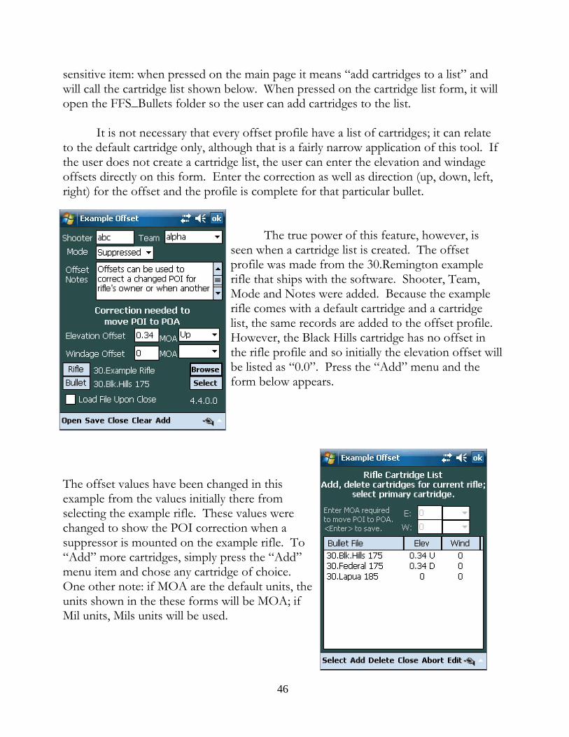
sensitive item: when pressed on the main page it means “add cartridges to a list” andwill call the cartridge list shown below. When pressed on the cartridge list form, it willopen the FFS_Bullets folder so the user can add cartridges to the list.
It is not necessary that every offset profile have a list of cartridges; it can relateto the default cartridge only, although that is a fairly narrow application of this tool. Ifthe user does not create a cartridge list, the user can enter the elevation and windageoffsets directly on this form. Enter the correction as well as direction (up, down, left,right) for the offset and the profile is complete for that particular bullet.
The true power of this feature, however, isseen when a cartridge list is created. The offsetprofile was made from the 30.Remington examplerifle that ships with the software. Shooter, Team,Mode and Notes were added. Because the examplerifle comes with a default cartridge and a cartridgelist, the same records are added to the offset profile. However, the Black Hills cartridge has no offset inthe rifle profile and so initially the elevation offset willbe listed as “0.0”. Press the “Add” menu and theform below appears.
The offset values have been changed in thisexample from the values initially there fromselecting the example rifle. These values werechanged to show the POI correction when asuppressor is mounted on the example rifle. To“Add” more cartridges, simply press the “Add”menu item and chose any cartridge of choice. One other note: if MOA are the default units, theunits shown in the these forms will be MOA; ifMil units, Mils units will be used.
46

The way the offset values are changed is to 1)highlight the cartridge of choice; 2) click the “Edit”item in the menu and choose “Offsets”. At that point,the offset part of the form at the top becomes active,the existing values associated with that cartridge areloaded in the appropriate boxes and are ready forediting.
As shown here, the values were initially 0.0for both elevation and windage. After tapping the“Offsets” choice the values 0.0 were imported to theedit section and that section is activated. In thisexample, the values 0.2 Dn and 0.3 Rt have beenadded. To accept these changes, tap the enter keyon the soft keyboard, generally shown by thissymbol: 5 . Continue in this way until all of theoffsets have been entered for all of the cartridgeschosen. If there is a cartridge on the list that is notwanted, highlight the cartridge, tap the “Delete”menu item and the cartridge will be removed.
Upon “Close” the changes made will await a “Save” of the changed file by theuser. If the user wants to abandon the changes, simply tap the “Abort” menu item andthe form will close with any change being discarded.
To the extent that a change to the offsets ofthe default cartridge was made, these changes willnow appear on the main form. In fact, when thereis a cartridge list, the only way to change theoffsets of the default cartridge is by going to thelist and making the changes there.
Upon loading the offset file, the effect ofthe offsets on the computed solutions will benoted on the main page. This is the main pageshowing the loading of this file.
47

Pressing the “B” button will bring up the cartridge list for the offset file, not the riflefile. The reason why is obvious: we are interested in the offsets for all cartridges on therifle as suppressed. To clear the offsets, click on the “Profiles” menu item, then select“Offsets” and “Clear Offsets” with the result being as shown. At that point, thecartridge list returns to the list associated with the rifle profile, in this case the“30.Example Rifle”. (You will see the change in the MOA solution although the turretsolution remains unchanged. This is a function of the turret itself which, in this case, isa 1 MOA/click turret so in this case the turret solution is the same. This will not bethe case for either 0.1 Mil/click or 1/4 MOA/click scopes.) Or, a more efficient wayto clear the offset is to tap the “O” button, tap and hold on the loaded offset file andchoose “Clear” on the resulting context menu.
The offsets concept is flexible and applicable to a variety of problems. It isanticipated that this feature can be adapted to many, many issues that lead to aconsistent change in POI. The offset profile may offer a solution for those issues.
D. The Rifle Profile
The rifle profile has three major functions:first, it is a location to associate a primary bulletprofile, all related cartridges used by the rifle, and aturret profile which will be loaded at the same timea rifle profile is selected; second, it refines the twistdata to exactly that of the rifle in question; third, itpermits the saving of rifle systems that may be usedin a unit such that if someone in the unitexperiences a PDA failure, another member may beable to quickly obtain ballistic solutions for thatunit member’s rifle system by simply opening a riflefile reflecting his system.
The rifle profile, shown here, is comprised ofa main page which has relevant information aboutthe rifle, including the bullet and turret profile to
use, a round count page where daily round expenditures can be logged and a notespage where problems or maintenance reminders can be recorded. Once a bullet profileis selected, the bullet label becomes an active button that will open the bullet profiler toenable the user to make changes to the bullet profile while in the rifle profile workarea. The same thing is true for the turret once it is selected. This is designed to savetime and present a compact manner of data presentation.
48

Of note is the “Shooter” text area where the user identifies the primary shooteror owner of the rifle. This data is loaded into the program to keep track of who isshooting for logging purposes. The shooter ID, usually initials or call sign, is shownon the main page. A small item, but helpful in detailed record keeping.
The “Add” menu is context sensitive. On the primary page, tapping the “Add”menu item opens a cartridge list where all cartridges that the rifle may shoot are to belisted. Because it is expected that the scope will be zeroed for the primary cartridge,the list of cartridges also can be associated with elevation and windage offsets so thatthe same scope zero can be used without modification.
This list is also available from the mainprogram page by tapping the “B” button whereuponthe cartridge list will be presented and any listedcartridge can be selected. When in the list, “Add”will open the bullets folder where additional cartridgescan be selected. The “Select” menu item selectswhichever cartridge is highlighted for importationback to the main page as the default cartridge for therifle. Not only will the cartridge be imported, butwhatever offsets are listed will be imported as welland when the rifle profile is loaded, the defaultcartridge will also be loaded along with its offsets. Generally, it makes more sense for the defaultcartridge to have zero offsets meaning that the scopeon the rifle is zeroed for that cartridge. However, theprogram is flexible enough to accommodate cartridgeswith offsets should the need arise.
The “Folder” link shown can be ignored at this point. For more information onhow and when to make use of this rather powerful feature, see Advanced DirectoryManagement in this manual.
49

Choosing the “Count” tab near the bottom of the main form brings up a formon which round count with appropriate notes can be kept. Below is a screen shot ofan actual record for a rifle in use along with the detail of a particular entry. To edit anexisting entry, double tap the entry. To add an entry, tap “Add” on the menu. Thefunctionality of the menu item has changed due to the context.
The third form available in the rifle profile can be accessed with the “Notes”tab. This is a place to include any information deemed related to the rifle system. The“Edit” menu item has a variety of editing functions. At the top of the page is a“Write” button which will allow the writing of the notes to a file which will, by default,contain the name of the rifle profile and be stored in the FFS_Rifle directory. Theuser is free, however, to name the file whatever he chooses and store it where hepleases. If the “Append” check box is checked, the existing notes will be appended toany existing text file specified. If the Append box is unchecked, the notes material willoverwrite whatever is in an existing file.
If the user presses and holds the Write button for ½ second, the buttonfunctions as a “Read” button and will open an Open File Dialog list with all of the textfiles found. Thus, in this mode the user is allowed to import any text file into theNotes text window.
E. Saving a Complete Solution
Although the Solution item is listed in the profile menu, it technically isn’t a
50
profile at all. Basically saving a solution means to save the entire setup as it then exists. The program does this automatically each and every time the program exits. This ishow the program can start from where the user left off in a previous session. Whenthe program starts it looks for a file called “eSession”, opens the file and loads the datasaved from the previous session. The only time when there is no eSession file is thevery first time the program starts.
The value of saving a complete data set is limited. It is helpful if an area wherethe user generally shoots has a fairly consistent weather pattern and the user shoots thesame rifle system. It is also helpful if the user wants to save a particular setup forfurther analysis at some later time. The program comes with a standard solution called“Reset” which causes everything to zero out to bring the program back to a zero state. A user may make other “zero state” solution files by setting up the program with thebasic elements he wants and then saving that solution.
F. Targeting Profiles
Targeting profiles are simply FFP, Position Target and Direct Target files. TheFFP and Position Target Profiles have similar data as the Map Ranging form and thefiles are interchangeable, the difference being that the profile form allows for the entryof notes and comments. Thus, the FFP and Position Target Profiles can have moreextensive data associated with them than a similar file created in the Map Ranging file. Both files, however, can be brought up and read in either form. The Direct TargetProfile takes the user to a form very similar to the Direct Target Ranging form andidentical in content.
As with all profiles, after creating a Targeting Profile, the user can elect to savethe data and/or load the data into the program upon closing the form (“Accept”) orabandon the data with or without saving it first.
G. The Turret Profile
1. The Simple Turret ProfileThe purpose of the turret profile is to provide an elevation that is correct for the
user’s scope. The problem is this: assume that the calculated elevation required for aparticular range and cartridge is 11.6 Mil (41 MOA). If the scope’s click value iscorrect, it is fairly simple to dial the calculated elevation. But if the click value issomewhat in error, dialing the calculated elevation becomes more of a challenge. Say,for example, that the click value on a particular user’s scope is not 0.1 Mil/click, butinstead is 0.105 Mils per click. In that event dialing 11.6 Mils would result in an actual
51

movement of the reticle equal to 12.18 Mils (0.105 Mil/click x 116 clicks.), 0.58 Milstoo much. The bullet is going to hit almost 0.6 Mils high.
The way to deal with turret click value errors is to create a turret profile wherethe user will input the “nominal” click value, i.e., the value that the manufacturerintends it to be (in our example 0.1 Mil/click) and the “actual” click value, onecomputed by the user when using the scope calibration techniques explained elsewherein this manual. With these two values, the program can compute not only the requiredelevation, but the “turret elevation”, the elevation that needs to be dialed on the user’sscope in order to move the reticle the calculated amount. Going back to the aboveexample, for this particular scope in order to actually move the reticle 11.6 Mils, theuser would only have to dial 11 Mils (11 Mils x 0.105 = 11.55 Mils). The turret profile,when loaded into the program, will calculate the correct elevation the owner of thisscope must dial and present that value in the “Turret Solution” windows on the mainpage.
In order to make a simple turret profile, the user need only calibrate his scope todetermine the “actual” click values, put in both nominal and actual elevation andwindage in the profile, state the zero range and scope height. The profile is finishedand usable. For the “simple turret profile,” the rest of the profile form can be ignored. Everything below the horizontal line shown in the Turret Profiler (see next graphic) isoptional.
2. The Complete Turret ProfileIt is possible to convert an elevation calculation into the equivalent turret scale
setting. The key to making a complete turret profile is to record the turret scalenumbers and associated click values in the lower half of the turret profile. Essentiallywhat this entails is starting from 0 and then sequentially entering the turret numbers ofthe elevation turret and for each number entered, also entering the number of clicksfrom zero that turret number represents. Below are three examples: a multi-revolutionturret such as is found on many 1/4 MOA scopes; a one or two turn turret such asfound on many Mil turret scopes today; and a BDC turret. Irrespective of the type ofturret, the idea remains the same: the Turret Profiler gets from the user actual andnominal click values for both elevation and windage, the scope zero, the scope heightand the association between the turret numbers and the related clicks for that numberso that the program can convert a calculated elevation into an equivalent turret settingusing the actual click value for that particular scope.
52

Example 1: a multi-rev turret that has an actual 0.26 MOA per elevation click (changethe value from 0.25 to 0.26 for this example.)
Multi-Rev type turret: Open the “Example Multi-Rev” turret fileTurret Number Scale: 0 1 2 3 4 5 6 7 8 0 Number of Clicks: 0 4 8 12 16 20 24 28 32 36
The actual numbers on this turret only go to the number “8” but it is necessaryto account for the complete rotation and in this case it takes 36 clicks to make one complete rotation where the beginning number “0” appears.
These numbers are entered in pairs, first thescale number and second the associated number ofclicks. In the example at the right, the numbers 4and 16 have just been entered and ready to be stored. Next it is necessary to add those data points tomemory, so the user taps the “Add Data Points” bar. The program stores that pair of numbers, goes to thenext position and waits for the entry of the next pair. When the last pair is entered this way (the 0 and 36pair), the user taps “Save” to save the turret file. Assuming the other data items have been entered,the turret profile is complete.
Note the little box to the far left of the “AddData Points” bar. That is simply a counter indicatingwhich number pair is being entered. In this case it isthe fifth pair (remember, it starts from 0 not 1), 4 and 16. After these points have beenadded, the counter will advance to 5 and the “Scale” and “Clicks” windows will beblank waiting for the next pair of numbers.
Important Note: The Multi-Rev turret is the simplest to make since werecord the scale numbers and their respective clicks for a single turn only. Once the Scale/Clicks data has been entered for a single, complete revolutionthat part of the data entry is done. Do not continue to enter data past thatsingle revolution.
53
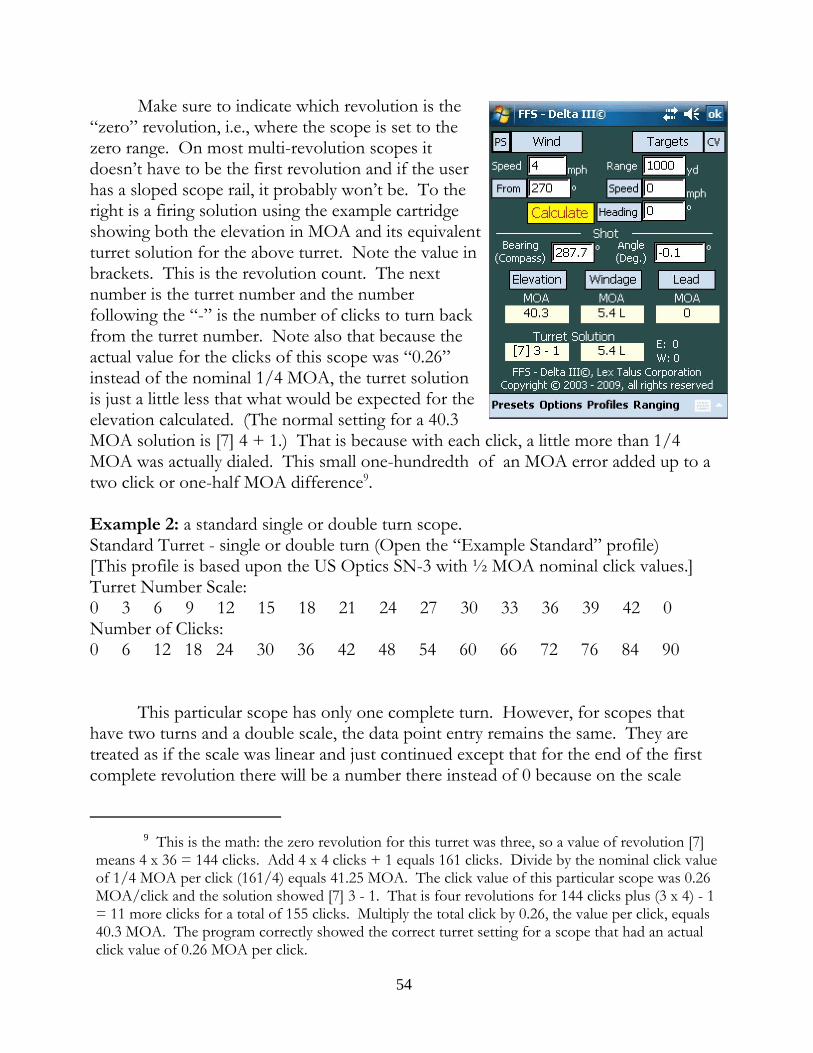
Make sure to indicate which revolution is the“zero” revolution, i.e., where the scope is set to thezero range. On most multi-revolution scopes itdoesn’t have to be the first revolution and if the userhas a sloped scope rail, it probably won’t be. To theright is a firing solution using the example cartridgeshowing both the elevation in MOA and its equivalentturret solution for the above turret. Note the value inbrackets. This is the revolution count. The nextnumber is the turret number and the numberfollowing the “-” is the number of clicks to turn backfrom the turret number. Note also that because theactual value for the clicks of this scope was “0.26”instead of the nominal 1/4 MOA, the turret solutionis just a little less that what would be expected for theelevation calculated. (The normal setting for a 40.3MOA solution is [7] 4 + 1.) That is because with each click, a little more than 1/4MOA was actually dialed. This small one-hundredth of an MOA error added up to atwo click or one-half MOA difference9.
Example 2: a standard single or double turn scope.Standard Turret - single or double turn (Open the “Example Standard” profile)[This profile is based upon the US Optics SN-3 with ½ MOA nominal click values.]Turret Number Scale: 0 3 6 9 12 15 18 21 24 27 30 33 36 39 42 0 Number of Clicks:0 6 12 18 24 30 36 42 48 54 60 66 72 76 84 90
This particular scope has only one complete turn. However, for scopes thathave two turns and a double scale, the data point entry remains the same. They aretreated as if the scale was linear and just continued except that for the end of the firstcomplete revolution there will be a number there instead of 0 because on the scale
9 This is the math: the zero revolution for this turret was three, so a value of revolution [7]means 4 x 36 = 144 clicks. Add 4 x 4 clicks + 1 equals 161 clicks. Divide by the nominal click valueof 1/4 MOA per click (161/4) equals 41.25 MOA. The click value of this particular scope was 0.26MOA/click and the solution showed [7] 3 - 1. That is four revolutions for 144 clicks plus (3 x 4) - 1= 11 more clicks for a total of 155 clicks. Multiply the total click by 0.26, the value per click, equals40.3 MOA. The program correctly showed the correct turret setting for a scope that had an actualclick value of 0.26 MOA per click.
54

itself there is an actual number that starts the second revolution.
The rest of the data entry is the same in terms of entering the actual andnominal click values, the zero and scope height, but the “Zero Rev” is meaningless sowithout the “Multi-Rev” box being checked, all is grayed out as can be seen in thegraphic to the lower right.
What about the “IFR” box? IFR stands for “Incomplete Final Revolution” andapplies to scopes that do not completely revolve 360 degrees for the final revolution. For example, certain Schmidt & Bender PMII scopes that have the Mil turret areapproximately a 1 and ½ turn to go from 0 to the maximum elevation of 26.5 mils. The first revolution goes from 0 to 17 mils which is one complete revolution. Thesecond revolution starts with 17 but ends short of the 0 mark and goes only to 26.5. In these cases, the user must check the IFR box.
The reason why this is important has to do with how the computer will convertnegative elevations into a turret equivalent. For example, if the Example Standardscope is set to a 200 meter zero, to adjust for 100 meters the scope must be dialed downa few clicks. On the following page are two graphics showing the result in a rifleshooting typical .308 Win. ammunition with a 175 gr. bullet. Note that in the case ofthe complete second revolution, the turret solution can be shown by going backwardson the turret and using the numbers on the second scale. (The same thing wouldhappen in the case of a single revolution turret where it makes a complete firstrevolution. This isn’t always the case as shown inthe BDC disussion below.) However, where thesecond revolution is short, it would make no senseto begin counting backwards from the last numbersince it would take many clicks to get to the lastnumber. Rather, the program will simply subtractthe number of required clicks from 0. Anything elsewouldn’t make sense.
To the right is a turret profile for the Schmidt &Bender PMII which has an incomplete secondrevolution. The ‘IFR” box is checked to denote thatcondition. As a result, when a negative settingneeds to be made, the turret solution will denote thiscondition by showing zero and a negative number. See the two examples which follows:
55

Complete Revolution
Here the solution is expressed in terms of thefirst turret number below the “0” which is“42.” Because the turret completed its last(which can be the only) revolution, countingbackwards makes logical sense.
Incomplete Final Revolution This shows a Schmidt & Bender PMII with aMil turret which does not complete the secondrevolution. To show a negative elevation, theturret solution does not show the next numberbelow “0” because that next number would be26.5, many clicks below the 0. Therefore, withthe “IFR” box checked, the program does notlook for the next lower number, but calculatesthe turret solution by simply subtracting the number of down clicks from zero.
The PDA program comes with example turrets so the user can open theexample turret and move through the pairs to see how it is done. Do not bediscouraged if the program produces an error when the new turret profile is used. Carefully check the data, particularly turret data pairs. Step through the pairs and makesure that they have been entered properly. If not, simply change the values and tap the“Add Data Points” for each changed pair. If the profile is still not working, send thefile to [email protected] and ask for help in tracking down the problem.
Positive Click ValuesThe turret solution may show a cardinal number and either plus or minus a
given number of clicks from that number, such as 4 + 3 or 5 - 2. Some users may notwant the turret solution to show negative offsets but would rather have all turretsolutions in plus clicks only, so instead of 5 - 2, they would rather see 4 + 8. Toachieve this output, choose “Positive Click Values” listed at Option->Turret Optionson the main page. With this option checked, all turret solutions will show only positiveclick values except for negative elevations involving IFR turrets. Those solutions willcontinue to show a negative offset from 0.
56

Muzzle Velocity from a Chronograph
The chronograph indicates the bullet’s velocity at the location of the measuringunit, not at the muzzle. The military obtains “muzzle velocity” data that is actuallyproduced at 78 feet from the muzzle. It is common for private shooters to measurebullet velocity at 15 to 20 feet from the muzzle. What is clear is that this data reflectsthe bullet’s velocity at some point downrange from the muzzle; the actual muzzlevelocity needs to be derived from this downrange data. The program has a tool to helpthe user in this regard. Choosing Options->Tools->Calculate MV->Chronograph willopen a workspace for this purpose and will permit the user to calculate the actualmuzzle velocity of the bullet based upon the chronograph data. The distance to beused is measured from the muzzle to a point midway between the two photo-sensors.
POI Method - Muzzle Velocity in the Field
After obtaining the muzzle velocity of any given cartridge by using achronograph, it is essential to check the data by confirming the trajectory at a rangebetween 300 and 600 meters. The program has a tool to help the user in this regard. Choosing Options, Calculate MV, POI Method will open a workspace designed tocorrelate the point of impact on the target with a muzzle velocity. The user may askwhy this step is necessary given the fact that the muzzle velocity has been measureddirectly by a highly precise piece of equipment. “Highly precise” doesn’t necessarilymean “accurate.” A chronograph is not self-calibrating and there is no way for mostshooters to determine whether his chronograph is outputting accurate numbers. Usingthe POI method to determine muzzle velocity is a good way to check the chronographand these checks may show that the user’s chronograph is habitually giving resultsabove or below the actual muzzle velocity.
This tool can also be used to determine the muzzle velocity of cartridges wherea chronograph is not available. Essentially, the user must have knowledge of the bulletused in the cartridge and its ballistic coefficient and weight. The user will also need toknow at least the published muzzle velocity value and with these numbers can fill inthe Presets page. Set a target at 300 to 600 meters and set the elevation as calculatedby the program. Assuming that the weight and BC are correct, any deviation from thetrajectory will result from an incorrect muzzle velocity. Input the distance above orbelow the point of aim that the bullet strikes the target and the program will calculatethe muzzle velocity necessary to have placed the bullet where it did.
57

Field Zero
In the Options->Tools menu there is a Field Zero item. The form comes withits own explanation which can be accessed using the on form Help menu. Insummary, the field zero function enables a user to verify a previously set zero using arange that is shorter than the zero range. This is a common problem for anyone whoarrives in an area of operations after transport of the rifle system and finds that thelocal area does not permit marking off enough range to verify that the rifle’s zero hasnot changed. The Field Zero tool allows the use of a shorter range and predicts wherethe bullet strike should be, relative to the point of aim, given a specific zero. So, if arifle is zeroed at 500 yards but the user has only 75 yards to check the zero, dependingupon the exact atmospheric conditions, the round should be hitting around 9 inchesabove the point of aim (Federal 308 Match) to reach a zero point at 500 yards. While itwould clearly be better to check the zero at the zero range, where that is not possible afield zero is the next best thing. The Field Zero form can also be used to change thescope’s current zero range to a new range. Just change the “Zero Range” and see whatthe point of impact should be for that zero range, adjust the scope until the bullet ishitting that spot. The scope has effectively been re-zeroed to a different range.
Fixed Zero
A related subject to the Field Zero discussion above is the concept of a fixedscope zero. In the physical world when a rifle is zeroed, it is zeroed in certainatmospheric conditions which dictate the trajectory and influence the muzzle velocityof the projectile. At some later time and in another location, the conditions might bevery different, but the scope is set up for the earlier conditions. Where is the zero?
Assume that a rifle system shooting Federal 308 Match ammunition was zeroedat 700 yards on an standard ICAO day . The next day the rifle and shooter aretransported to a location with an altitude of 5000 ft. The temperature is 75 degrees Fand the station pressure is 23.6 in. Hg.. Where is the zero? The relationship betweenthe rifle and the scope has not changed, but the trajectory at 5000 feet is going to beflatter than it was at sea level. In fact, with the scope set for 700 yards at sea level, at5000 feet and 75 degrees F the bullet will be impacting the target 1.1 MOA high at 700yards. The actual zero has changed to approximately 733 yards.
It is possible to use this program to account for this change without having tore-zero the rifle. When the zero is first obtained, the user can “fix the zero” by 1)insuring that all of the atmospheric and bullet conditions are entered into the computerand then checking the “Fixed Scope Zero” box in the turret profiler. (In this case
58

enter a standard ICAO atmosphere, use a Federal 308 Match cartridge and assume amuzzle velocity of 2600 fps.) The program no longer assumes a constant zero of 700yards (which requires a constantly changing or floating reticle to match changingconditions) but assumes a fixed reticle and allows the zero range to change based uponcurrent conditions. The zero range is allowed to change as conditions change; thescope’s setting is fixed.
At sea level the above scope zeroed at 700 yards will require an additional 12.4MOA to get to 900 yards. At the new location of 5000 feet ASL, a scope zeroed for700 yards under standard 5000 foot conditions will require only 10.3 MOA to get from700 yards to 900 yards. But a scope zeroed at sea level conditions for 700 yards andthen taken to 5000 feet (using the atmospheric data above) and without changing thezero would require only an additional 9.3 MOA to get to 900 yards. The reason why isthat the scope zeroed at sea level but fired at 5000 feet is now shooting 1.1 MOA highat 700 yards. Because of the elevated impact point it takes fewer MOA to get to 900yards.
When a rifle has changed locations, the user may either re-zero his scope orkeep his sea level zero and check the “Fixed Zero” box and allow the program tocalculate the turret settings under these new atmospheric conditions. The advantage ofnot having to re-zero with every change of location is obvious. The program will makethe adjustments and give the proper elevation if the user has “fixed the zero” for theoriginal conditions under which the rifle and scope were zeroed.
Note that this advantage disappears for close zeros. The difference betweenpoints of impact for a 100 yard zero at sea level and a 5000 foot 100 yard zero is 0.022"or 0.021 MOA (for .308 Win. match ammunition). For all purposes, that zero is notmaterially different. If the user uses close zeros under 200 yards or, perhaps, even 250yards, he need not be concerned with shifting zeros in changing conditions. A riflezeroed at 300 yards, on the other hand, will see a zero shift in POI of nearly 3/4", aquarter of an MOA, and perhaps enough to justify the “Fixed Zero” option. The useris encouraged to experiment to see what changes may occur given his particular zeropreference. Remember, these figures are only valid for .308 Win. match ammunition. Different calibers/cartridges will yield different results and flat shooting cartridges maynot have significantly changed zeros out to as far as 400 yards.
59

Wind Speed at Range
Figuring out the wind speed at range is something of an art. There are handyand highly portable wind measuring devices that accurately measure wind speed butthose will tell the wind speed only at the shooter’s location. Most long range shootersdevelop skill in doping the wind at range by looking at mirage and the movement ofgrass, bushes and trees. The FFS program offers an additional tool in this regard.
Tapping the “Wind” button brings up the Wind Vector screen. At the bottomof this screen is a “Wind Speed Calculator”. If the user can see some air borneparticulate matter at a known range, the user can measure the movement of the matteracross the reticle while timing the movement. Basically the user will have timed moving material over a known distance for a known time which can be used tocalculate a velocity of the particulate matter which should equal the wind speed.
Example: Say at 950 yards is some burning rubble and the smoke is movingfrom left to right across his field of view. The shooter starts the timer as the smokecrosses the far left edge of his reticle and when the smoke crosses the far right edge ofthe reticle he stops the timer. The shooter knows that the entire horizontal element is10 mils wide. When he stops the timer, 1.9 seconds have elapsed and the calculatordeclares that the smoke is traveling at 3 mph. That value matches the wind speed hemeasured at his shooting location so he is confident 3 mph is a good value to use overhis course of fire.
So how does the shooter tap the “Start” and “Stop” buttons while he is trying towatch the smoke through his scope? Well, he doesn’t have to. The timer in WindVectors screen is tied to the button cluster hardware on the front of the PDA,specifically the “Enter” button. Generally the center button of the cluster is the“Enter” button and the first push will start the timer while the second push will stopthe timer. Essentially the program turns the PDA into a stopwatch. The shootermerely puts his thumb on the Enter button, looks through the scope, starts the timerand then stops the timer without ever having to look away from the scope. The resultsappear automatically.
If the shooter wants to use the results of the calculation, he checks the box touse the calculated value and exits. When he is using more that one wind zone, the“Use calculated wind speed” box is grayed out because the program can’t know whichzone the calculated value applies to so the user will have to enter the value in theproper speed box.
It is important to note that when observing wind effects through the scope, the
60

shooter is seeing only the component of the wind that is moving at right angles to theline of sight and the speed measured is not wind vector but only that perpendicularcomponent of the vector. Therefore, when the "Use calculated wind speed" box ischecked, the program will change the wind direction to either 90 or 270 degreesdepending upon the direction of the wind originally shown. Example: if the wind ismoving from the shooters left rear at 245 degrees, breaking the wind into itscomponents , a portion of the wind is moving across the direction of bullet travel fromleft to right (from the 270 to 90 degree direction) and a portion of the wind is movingalong the direction of bullet travel from shooter to target. For calculating winddeflection, we ignore the tail wind component and use the cross-wind component. Ifwe use the wind timer, we are measuring only that component of the wind vector thatis moving from 270 to 90 degrees; therefore, upon checking the "Use calculated windspeed" box, the wind direction will change from 245 degrees to 270.
Target Fix & Speed at Range
A similar work area exists for obtaining the speed of a target at range as existsfor obtaining wind speed at range. On the main page in the Target section is a "Speed"button that normally toggles the speed units. By holding the button down for longerthan about 1/2 second, upon release a target speed timer appears. As for the windspeed timer, the "Enter" button will start and stop the timer and by observing thetarget through the scope, the target's speed across the reticle can be timed andascertained assuming that the shooter has the target's range. To use the computedspeed, simply "Accept" the result and it will be imported back to the main page wherea firing solution will be computed.
Note that, like wind, only movement of the target perpendicular to the target's bearingcan be measured so the user must indicate whether the target is moving towards theright (90 degrees) or left (270 degrees). Any part of the movement either towards oraway from the shooter is ignored.
When a range finder is attached to the PDA, the "Speed" button functions in asimilar way except that upon holding and releasing the button a target fixing page isshown. Because the shooter has the ability to exactly range the target with the rangefinder, he has the ability to take two "fixes" of the target's position at two distinctpoints in time. The shooter therefore ranges the target which places the first fix on theform and starts the timer. The shooter then takes the second fix. The range, bearingand angle is input into the program as the second fix data, the timer is stopped, and theprogram accurately computes the target's speed, bearing (relative to the shooter) andangle. Upon accepting this computation, these data items are imported back to the
61

main page where a firing solution is computed.
As a backup in case of a failure of the range finder, it is possible to performthese fixing tasks manually by inputting the range, bearing and angle data by hand,starting and stopping the timer by hand and hitting the calculate button. While"possible" this mode of target speed calculation is not particularly feasible; better to usethe target timer or even the wind timer if keeping the range finder connected isrequired.
The Elevation Table
The main page gives the results of the trajectory computation at the target range. By tapping the “Elevation” button the user can get elevation data for any number ofranges. The elevation table displays its data in labeled columns. The column headerson some of the columns will change what the column displays by tapping on theheader. For instance, the “Turret” column shows the turret setting for ranges from the“Start” range out to the “End” range (or the target range, whichever is farthest.) Tapping on the Turret header shows the time of flight of the bullet to the listed ranges. This data is helpful in computing or estimating lead for a moving target. Tapping theheader again will list the bullet velocities at each range so the user can be aware of therange that the bullet will go subsonic. Tapping on the header again will cause the datadisplayed to return to Turret data. The next column is the Elevation column andshows the elevation in terms of Mils (or MOA depending upon the user preference.) Tapping on the Elevation column will list the vertical holds from the current targetrange to the other ranges listed in the range column. This feature was added to enablethe user to quickly access targets at different ranges simply using the reticle to hold off. Tapping again causes the data to be displayed MOA (or Mils, whichever was notshown initially.)
The windage column shows the windage at various ranges for the given windcondition from the main page. Tapping the wind header will alternate between MOAand Mils click values. This is especially valuable for the shooter who has a Mil-dotreticle but has MOA elevation and windage turrets. Clicking on the wind column willpermit the Elevation to be shown in Mils while the Wind is shown in MOA thuspermitting a turret adjustment for wind while holding off for elevation. Columnheaders for Lead work in the same way. Just work with the table for a while to seehow flexible it is in displaying the appropriate data.
Further with respect to the Lead column, if the user employs an“uncoordinated” scope where the turret units differ from the reticle units, the user will
62

generally want the elevation and windage solution to reflect the turret units while leadshould be given in the units employed by the reticle. On the main page it is possible toselect the basic units of the display from the Options list. The user may then choosewhich units should be used for the lead solution by tapping the Lead button. Whichever units are selected, those are the units which will be initially displayed for theLead column in the Elevation table.
The Range column toggles between yards and meters. To select any given rangefor import back to the main page, double tap on the range value of interest. TheElevation window closes and the selected range becomes the new target range. Afiring solution is then automatically computed.
Using Turret WindageThe Elevation table shows the needed calculated windage required given the
current conditions for the various ranges listed on the table. If the user has calibratedhis scope and has found that the click value of his windage turret is not as advertisedby the manufacturer, he may want the windage output in terms of what he must dial onhis scope given its actual click value. If the user wants windage “corrected” to hisparticular turret, he selects “Use Turret Windage” on the Options list from the Mainpage. The windage column now lists windage modified by the windage turret error andmay be used to dial windage directly.
Using the Capture FunctionThe content of the Elevation Table can be exported in the form of a CSV
(comma separated values) text file which can be opened in Excel® or similarspreadsheet for the purpose of creating a hard copy range card. The user is free tomodify the data presented, organizing it in ways that best fits his preferences. Toobtain the data contained in the table, select Capture->Current Table. All data in thetable will be written to a CSV file which the user can find in the \Documents directoryon the card. Copy this file to a desktop computer for opening in a spreadsheet andthereafter editing the columns, presentation, format and the rest. Please note that theturret column data can be interpreted by the spreadsheet program as a date. In orderto avoid this, instead of merely opening the file in the spreadsheet, import it and duringthe import process specify that particular column as a text column.
If the user wants to make several field cards for the same bullet profile but withchanging atmospheric values, simply create the file as instructed above but leave thedata file in \Documents, exit the Elevation Table, make changes to the Presets page,re-enter the Elevation Table and tap on the Current Table menu item again. The newtrajectory data will be appended to the original file. The user may repeat this sequenceuntil all of the various conditions for that cartridge have been exhausted. At that point,
63

move the file to the desktop computer, open it in a spreadsheet program and the userwill see individual trajectory blocks for each condition saved.
It is possible to create extended Density Altitude Tables for a given cartridge aswell. Clicking on the Capture->Den. Alt. Tables item will take the user to a formwhere he can specify the altitude range of interest and specify the size of the step orinterval. It is recommended that 500 or 1000 feet (200 or 500 meters) be used, but it ispossible to enter any value. If the user wanted a study of changes from 500 to 750meters at 10 meter steps, he would select the lower and upper boundaries and thenenter 10 in the Step window, then “Accept”. A rather lengthy file with 25 separatetables would be found in the \Documents directory ready for further editing in aspreadsheet.
It should be noted that the Abridged density altitude tables can reflect elevationin terms of the user’s turret, i.e., the elevation that must be dialed given the click valueerror of the user’s turret, as well as the impact upon elevation calculation due topowder temperature changes as altitude increases. If the user has loaded a particularturret file into the program, the various elevation columns in the table will reflectelevation settings for that turret; therefore, if the user wants “pure” elevationcalculations unaffected by a particular turret he merely has to clear the turret (Profiles->Turret-> Unload). Similarly, if the “Powder Temperature” option is selected, as thedensity altitude increases, the standard temperature decreases which may affect muzzlevelocity and hence downrange performance. To obtain a table with a constant muzzlevelocity, simply turn off the “Powder Temperature” option.
Density Altitude tables can be a good backup in the event that programfunctionality is lost and the user is encouraged to learn more about the uses of this typeof table on his own.
The Windage Table
The windage table is accessed by tapping the “Windage” button and showswindage needed for various wind speeds in addition to the wind specified on the mainpage. Note that when wind zones are being used, the Windage button is grayed outsince it is not possible to present wind solutions in a multiple wind scenario. But whena single cross-wind is specified, the table shows corrections for wind values from 0 to40 mph (0 to 70 kph) and shows windage offsets from the specified wind.
This feature exists to enable the shooter to deal with a changing wind. Forexample, say the prevailing or average wind across a range of fire is 4 mph but that the
64
wind varies from 2 to 6 mph. The shooter can see that for a given range as the winddies or increases he can adjust by holding the amount shown in the hold off column. So he dials for 4 mph and then varies his hold to account for wind changes. The tabletells him how much to hold for any wind condition for the given range. As with theElevation table, any wind value can be selected by double tapping on the value.
The second column shows holds that assume that a windage value has beendialed and as the wind changes speed, the shooter can hold either left or right theamount shown. The fourth or last column assumes that the windage is not dialed, butheld and the amount to hold is shown, starting at zero (where only the spin drift andCoriolis deflections, if any, are shown.) The third column shows the Net Hold,particularly useful for a moving target and a variable wind. This column assumes thatno windage has been dialed and the net value of adding the wind correction and thelead value is shown. This value also incorporates the spin drift and Coriolisdeflections.
Using Turret WindageThe Windage table shows the needed calculated windage required given the
current range for the various wind velocities listed on the table. If the user hascalibrated his scope and has found that click value of his windage turret is not asadvertised by the manufacturer, he may want the windage output in terms of what hemust dial on his scope given its actual click value. If the user wants windage“corrected” to his particular turret, he selects “Use Turret Windage” on the Optionslist from the Main page. The windage column now lists windage modified by thewindage turret error and may be used to dial windage directly.
Note that the hold off column is not affected. Hold offs are a function of thereticle and are not affected by turret error so the hold offs listed are true, uncorrectedvalues.
Getting and Using Magnetic Bearing
Obtaining bearings to a target can be done via a map, in which case truebearings can be used. But in the field getting a target bearing is generally accomplishedwith a compass in which case the user will be gathering data in terms of a magneticbearing. Therefore, the program needs to handle both true bearings (map bearings)and magnetic bearings (compass bearings) with equal ease. This also means that a wayto obtain the magnetic variation of a particular location is required. Magnetic variationis not constant across the entire globe but varies by locale and in fact changes overtime. Unless the user has access to local, current maps, he might not know what the
65
local magnetic variation value is and can not therefore obtain reliable compassbearings. The problem is solved by using data and coding prepared by the NationalGeospatial-Intelligence Agency for its World Magnetic Model. If the user will look atthe SD card with the PDAs File Explorer and find the FFS_Data folder he will find afile called “WMM”. On the desktop this file can be opened using Notepad and thecontent reviewed. Essentially this file contains a database of the magnetic variations allover the world and permits the program to compute a specific magnetic variationbased upon a specific set of coordinates. While the variation calculated is not exact, itis very much accurate enough for use in this program.
First, the program needs to know where it is or at least what location thecomputed firing solutions are going to be used in. One way to tell the program itscurrent location is to create location files in the Map Ranging form and then loadingthe appropriate file. Another is to connect a GPS device (either by way of a directplugin to a serial port or via Bluetooth) and to save the location it provides. Or, in theMap form, enter that data as a FFP and Accept that data. (In this latter method, whena new FFP is loaded, the old will be lost.)
For purposes of this explanation of how to use magnetic variation in theprogram, the assumption is that you have a location file or otherwise know how toinput a location (this will be explored in detail in the GPS and Map Ranging sectionsbelow.) Once a location is input, tap the “CV” button on the main form in the upperright hand corner. In this case “CV” means “Coriolis/Variation” and represents theaccess point to input the data needed to compute Coriolis acceleration. On theCoriolis page you will see that only the Latitude window is available for location. While only latitude is needed for Coriolis computation, to compute the magneticvariation both latitude, longitude and altitude is required. At the bottom of the CVpage is menu item “Compute” which takes the user to a page where the requiredlocation parameters can be input. If a GPS is connected and running in thebackground, the GPS menu item will be active and pressing it will cause the currentlocation parameters as reported by the GPS to be imported into the data text windows. Once this data importation is complete, the program will automatically compute themagnetic variation for that location. If the user wishes to use that data, he clicks“Accept” and will exit back to the CV page. Here he will see that the latitude forCoriolis purposes has been updated to the current location and that the magneticvariation has been brought in from the previous page. He can now opt to use Corioliscomputations by clicking the box and opt to use the magnetic variation value bychecking that box. At that point, the user must “Accept” his elections and exit or“Abort” what he has done.
If he has chosen to use Coriolis computations in the firing solutions, the Bearing
66
text box on the main page, which was yellow, is now white. This is a visual cue as towhether Coriolis is being used or not. Also, below the “Bearing” label there is anindication that the Bearing is “compass” meaning that magnetic variation is being usedand the bearing figure is a compass bearing. On the other hand, unchecking theMagnetic Variation box on the CV form will cause the Bearing to be “True”, i.e., thebearing as shown on a map.
Magnetic variation can also be selected as an option in the Options menu list. Ifit appears that no actual location has been input, choosing magnetic variation willresult in an advisory that “Magnetic Variation equals zero” which generally means thatthe program is using a default value and that a magnetic variation has not beencomputed. Choosing to activate Coriolis in the absence of a current location willprompt an advisory that “A current position has not been selected.” Looking at themain page will show “None” and the Presets page will show all zeros for current FFP, a sure sign that no current position has been input. The user is encouraged to let theprogram know where on earth the calculations relate to. The program can do manyother things if it knows the location of the firing position, as will be shown below.
Target Ranging
A. Direct Ranging
Opening the Direct Ranging page allows the user to manually input a range,bearing and angle and then save the file for later use on the Targets list. These are thetarget files that will appear when “Direct Range” is selected as the FFP.
B. Map Ranging
The purpose of the Map Ranging page is to input firing positions (FFPs) andtarget locations in the form of location coordinates for saving and use on the Targetslist. FFP location can be obtained one of two ways: 1) from a map; 2) from a GPS. Inthe first case, it is necessary to input either Lat/Lon coordinates, UTM or MGRScoordinates and an altitude manually and then save the files to some meaningful name. In the second case, the user can get the coordinates directly from a GPS running in thebackground. It is possible to connect a GPS to the PDA, open a serial port and leaveit running in the background so that various parts of the program can have access tothe location data it provides. In the map ranging page, when a GPS is running in thebackground the GPS menu item becomes active and pressing it causes the currentGPS coordinates and altitude to be inserted in the proper data text windows. At this
67
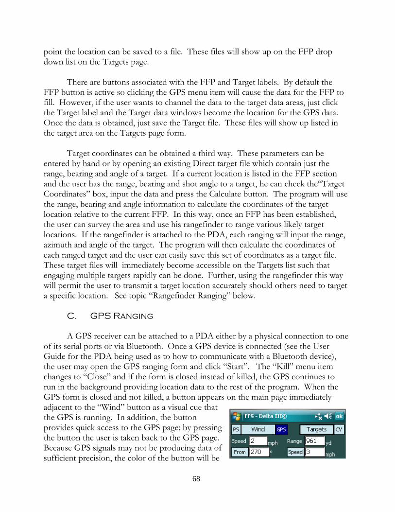
point the location can be saved to a file. These files will show up on the FFP dropdown list on the Targets page.
There are buttons associated with the FFP and Target labels. By default theFFP button is active so clicking the GPS menu item will cause the data for the FFP tofill. However, if the user wants to channel the data to the target data areas, just clickthe Target label and the Target data windows become the location for the GPS data. Once the data is obtained, just save the Target file. These files will show up listed inthe target area on the Targets page form.
Target coordinates can be obtained a third way. These parameters can beentered by hand or by opening an existing Direct target file which contain just therange, bearing and angle of a target. If a current location is listed in the FFP sectionand the user has the range, bearing and shot angle to a target, he can check the“TargetCoordinates” box, input the data and press the Calculate button. The program will usethe range, bearing and angle information to calculate the coordinates of the targetlocation relative to the current FFP. In this way, once an FFP has been established,the user can survey the area and use his rangefinder to range various likely targetlocations. If the rangefinder is attached to the PDA, each ranging will input the range,azimuth and angle of the target. The program will then calculate the coordinates ofeach ranged target and the user can easily save this set of coordinates as a target file. These target files will immediately become accessible on the Targets list such thatengaging multiple targets rapidly can be done. Further, using the rangefinder this waywill permit the user to transmit a target location accurately should others need to targeta specific location. See topic “Rangefinder Ranging” below.
C. GPS Ranging
A GPS receiver can be attached to a PDA either by a physical connection to oneof its serial ports or via Bluetooth. Once a GPS device is connected (see the UserGuide for the PDA being used as to how to communicate with a Bluetooth device),the user may open the GPS ranging form and click “Start”. The “Kill” menu itemchanges to “Close” and if the form is closed instead of killed, the GPS continues torun in the background providing location data to the rest of the program. When theGPS form is closed and not killed, a button appears on the main page immediatelyadjacent to the “Wind” button as a visual cue thatthe GPS is running. In addition, the buttonprovides quick access to the GPS page; by pressingthe button the user is taken back to the GPS page. Because GPS signals may not be producing data ofsufficient precision, the color of the button will be
68

dark until the precision of the data is of such quality deemed necessary for long rangeprecision work. At that point the color will turn to a light blue which puts the user onnotice that the GPS data is usable. In the graphic the data being received is notsufficiently precise for use so the button remains dark blue.
When the GPS serial port is open and GPS data is being received in thebackground, the data is available to: 1) the Coriolis/Magnetic Variation page; 2) theCompute Magnetic Variation form; 3) the Map Ranging form; and 4) the GPS Rangingform. The GPS Ranging form shows not only the current location, but the number ofsatellites being tracked, the quality of the data, the current location in both Lat/Lonand UTM or MGRS formats including altitude, the universal Mercator time as reportedby the satellites, the local time as recorded by the PDA, and, if traveling, the bearingand speed of movement.
Associated with the GPS Ranging page is a button located on the Local Timeline. Pressing this button will synchronize the PDA time to the satellite time.
Continuous PowerThe Mode menu item shows a “Continuous Power” option. Checking this
option prohibits the PDA from going into Suspend mode where the CPU wouldotherwise cease functioning, but instead keeps the PDA energized so that it willcontinuously receive satellite data. The backlight may power down, the unit itself willcontinue to run. Caution: Leaving the GPS running in “Continuous Power” preventsthe PDA from automatically powering down in accordance with the user settings andthus will result in the need to recharge the battery sooner than normal.
D. Range finder Ranging
Obviously a shooter can range a target byusing a rangefinder and then input the range into theprogram. This isn’t what is meant by “RangefinderRanging”. Clicking on the menu item Ranging,selecting Rangefinder and then selecting a particularrangefinder, the user will see the form to the right,this one pertaining to the Vector IV. This form is toenable and open a serial port to bring in ranging dataexported by the rangefinder. The range finders listedare those that have the facility to export the rangingdata via a serial cable which can be plugged into thePDA. Tapping the “Start” in the menu opens thePDA serial port and assuming that a Vector IV
69
rangefinder is attached to the PDA via the serial cable, each time the range button ispressed on the range finder, the range, bearing and angle will be transmitted to thePDA and displayed in the data boxes. The raw data feed will be displayed as well sothe user can inspect the raw data for problems.10
There are a limited number of ports on a PDA and those that are available arelisted in the drop down list. Double click on a port, click on “Start” and then press theranging button on the connected rangefinder. If the range finder is connected to theport which is open, the data will be displayed. If it isn’t, close the port and try another. If no port works, suspect that no signal is being generated by the range finder or thatthe adaptor cable is failing to transmit the signal properly to the appropriate pins of thePDA plug.
When the serial port is opened, the “Kill” menu item changes to “Close” whichis a visual cue that the form can be closed without killing the serial connection. If theform is “Close[d]” the serial port remains open and each time a range is taken, the datais received by the program and used in various places as discussed below. In addition,a button immediately adjacent to the “Targets” button becomes visible on the mainpage. This is a visual cue and reminder that the serial port is open. It is also a shortcutback to the Laser Ranging page. Instead of tapping the Ranging menu, Rangefindersand then Vector IV, simply click the “RF” button on the main page for immediateaccess to the to Laser Ranging page.
Once the serial port is open, the data generated by each ranging will bechanneled to: 1) the main page for instant firing solution computation; ) the LeadComputation form11 for use in rapidly obtaining target fixes to compute target speed
10 While range finder manufacturers list the baud rate in the specifications of their products,sometimes these specifications change and sometimes the specifications are erroneous for anyparticular device. For example, the Vector 1500 prior to 2004 had a specified baud rate of 1200;from approximately 2004 on, the baud rate was increased to 9600. Therefore, if user has trouble ingetting error free communication with the device, experiment with the baud rate setting. Althoughthe Vector IV has always been spec’d at 9600 baud, we have found at least one which outputs itsdata at 1200 baud.
11 On the main page there is a Speed button associated with Target speed. Generallypressing this button toggles the speed units. Pressing and holding the button will bring up a timerform for manually timing the target’s movement to calculate target speed. However, when a serialport for a rangefinder connection is open, the button’s function changes. Pressing and holding thebutton brings up a form on which the lead of a moving target can be automatically computedthrough two fixes from the rangefinder. The user presses the rangefinder button once to get therange, bearing and angle of the target in position 1, waits a period of time and then takes a second
70

and heading; 3) the Direct Ranging page where the range, bearing and angle data willbe displayed for saving in a direct target file; 4) the Map Ranging page for purposes ofusing the range, bearing and angle to compute the coordinates of the ranged target; 5)the Target Range Card where a target list from a current firing position can be quicklycreated by simply ranging targets in sequence, each target entry showing a range,bearing, vertical hold, and windage information for each target. (See the Target RangeCard topic for complete information.); and, of course, 6) the Laser Ranging page tomonitor the incoming data for troubleshooting purposes.
The routing of the range finder data to the Map Ranging page is especiallyuseful. If the user has the current coordinates set as the current FFP, going to the MapRanging page will fill the FFP location with the current data. Ranging a target with aconnected rangefinder will fill in the Range, Bearing and Angle windows on the form. Checking the Target Coordinates box will cause the Calculate button to calculate thetarget’s coordinates based upon the current location and the ranging data. The usercan then quickly save the target coordinates in a target file for later use on the TargetsList.
On the Target Ranging Card the data is handled similarly. If the FFP is set, eachranging causes the automatic calculation of the target’s coordinates and upon savingthe target group, each file is saved as a Position target file and is included in a targetgroup file for quick loading later.
Use Laser Data to Compute SolutionBy default when the program starts, this check box is checked and each time the
range finder ranges a target as solution is computed. However, when ranging targetsthat are beyond the practical range of the rifle or when the objective is merely to rangetargets for purposes other than engaging with the rifle, this box may be un-checked inwhich case the range finder data is still distributed throughout the program, but nosolution calculated. In addition, when the this box is unchecked the “RF” button onthe main page turns a dark blue as a visual cue that firing solutions are not beingcomputed. As an additional reminder the solutions windows show only “----” insteadof a numeric value. Therefore, when using the program to plot target locations on theMap Ranging page, uncheck the box, open the laser port, close the Laser Ranging pageand open the Map Ranging page. With the “Compute Target Coordinates” boxchecked and a current FFP location, each ranging will automatically calculate theranged target’s coordinates.
fix of the target. The program computes the speed and direction (relative to the shooter) of thetarget which can be “Accepted” back to the main page where a firing solution will be computed forthat target.
71

Compute Relative Wind DirectionThe range finder interface page has a check box labeled “Compute Relative
Wind Direction” which is selected by default. When selected, the user will see thewind direction on the main page change as targets are lased in order to reflect anaccurate relative wind direction for each lased target given its particular bearing. Unchecking the box will cause the windage direction to remain constant during targetranging.
E. Reticle Ranging
This form calculates the range based upon the height of the target, the size ofthe target as seen in the scope and measured in Mils or MOA.12 The resultingcomputed range can either be “Accept[ed]” and imported back to the main page forcomputation of the firing solution or “Abort[ed]”.
Next to the Target data window is a button which brings up a Size of Objectseditor. This editor permits the reading of lists containing the known size of variousobjects which may be encountered in the file. The editor also permits the editing ofexisting lists and the creation of new lists.
Editing an Existing List - make the required changes or additions and then pressthe “Save” menu item. All changes are saved to the existing file.
Making a New List - make changes to an existing list and then click on the“SaveAs” menu item. A file naming text window appears at the top of the screen. Tap<Enter> to save the file. (Tapping <Enter> on an empty screen aborts the process.) To create a brand new list, click on “New” and add the desired data. Then finish with“SaveAs” and enter the name of the file. Upon the creation of the new list, the dropdown menu is updated and the new file will immediately appear on the list.
Getting Size Data - the user can import a size number back to the ReticleRanging form by 1) highlighting the desired number and 2) clicking “Close”. At thatpoint the Size Lists form closes and the selected number appears in the Target sizewindow. The user must then ensure that the units (inches, feet, yards, centimeters, or
12 The form can also be used as a training aid in that it allows input of any twounknowns for calculation of the third. Thus a target of known size and at a knowndistance can be input so the shooter can see what the target of the calculated Mil sizelooks like in the scope.
72

meters) for the imported value are correct. Only the number may be highlighted; donot include any additional text such as units.
The Projectile Metrics Button
To the immediate right of the Range text window on the main page is a smallbutton whose job it is to display various velocity/range related projectile metrics to theshooter and therefore provides a quick way to see data related to the current range: theheight and range of the Maximum Ordinate, the velocity of the projectile and its totaldrop, the energy and momentum of the projectile, the speed of sound, and thetransonic boundaries as well as the maximum supersonic range, the maximum useablerange, and the maximum possible range for the bullet. (The speed of sound is not aconstant value, but changes directly with temperature: as temperature increases, sodoes the speed of sound.) These various data are informative and can quickly helpmake a decision whether a given shot has a high, medium or low hit probability.
Visual cues are given to the shooter when the range of any shot is 1) in thetransonic region but still supersonic, 2) in the transonic region but subsonic, and 3) outof the transonic region and subsonic.. In the case of conditions 1 and 2, thebackground color of the Range text window (main program page) changes color asdoes the small subsonic information button, a yellow hue for condition 2, a red hue forcondition 2. For conditions where the bullet is not in the transonic region and issubsonic, the window remains a red hue, but the button returns to the normal color.
The Log Button
The log function allows a user to record all pertinent data concerning a shotwith a single click of the “Log” button. The button is by default inactive to avoidhitting it inadvertently and logging unwanted data. To activate the Log button, go tothe Options->Tools menu and choose “Log Enable”. The Log key, previously grayedout, becomes active.
Pressing the button will record the date and time, the current location inLat/Lon, UTM or MGRS coordinates (depending upon your preference as revealed onthe Map Ranging page), the pertinent atmospheric conditions and the calculatedelevation and windage among other data items. The log entry also keeps a runningcount of each shot fired. The size of the log is limited only by the memory of thePDA.
73

The log file can be edited and can be saved under another name. This is a “txt”file and may be opened in Notepad on the desktop computer for easier editing or maybe edited on the PDA by just tapping on the file. The program has a Log Editor(Options menu, Tools, then choose “Log Editor” and open the “CurrentLogData”file) which may be used as well. All current log data is recorded to a default file called“CurrentLogData” and if the program doesn’t find a file by that name it will createone. Each log entry has a line for remarks so the user can add comments ordocumentation for any particular shot taken at some later time.
When the Log button is enabled, it is possible to call up the Log Editor bysimply tapping and holding the Log Button for one-half second. When the editing iscomplete, be sure to Save the changes and close.
By default the log entries are in reverse chronological order, the last event is atthe top of the file. Using the Edit menu item it is possible to change the default tohave the last entry place at the end of the file by unchecking the “Reverse Chron”. Inaddition, if the user has been keeping a log in one order, using the but wishes tochange the default, tapping the “Reverse Entries” Edit menu item will reverse allcurrent entries. Once the entries are in the order desired, tap the “Save” menu item tosave the file.
The PS Button
The PS button stands for “Profile Summary” and is a fast way to check whatbasic data is being used by the program including the atmospheric data, bullet data,which turret is currently being employed and data related to the Coriolis correctionmagnetic variation. It’s function is merely to quickly inform. In addition, the PS formcontains useful reference formulas, conversion factors and convenient menu access tothe calculator.
An interesting value displayed is the “Stability Factor.” The gyroscopic stabilityfactor is a value that shows how stable a bullet is as it exits the muzzle. The stabilityfactor must be at least 1.0 or the bullet probably will not stabilize thereafter; it will spinout of control, tumble, and generally fail to generate a useable trajectory. Generally, atnormal ICAO or Metro conditions, a stability factor of around 1.5 is a decent value. However, it is not uncommon to see stability factors of 1.2 to 2.5 or even higher. Thefactor is, therefore, a function of the density of the atmosphere and as the density thinsin warmer temperatures or higher altitudes, the stability factor will become larger.
The stability factor not only is affected by the atmosphere, it is also a function
74
of the barrel twist rate and various attributes of the bullet including its mass, diameterand length. As the stability factor increases, the angle of repose also increases whichmeans that the spin drift increases. The stability factor is therefore presented for tworeasons: first, it allows the user to quickly check to make sure that bullet is stabileunder current conditions; second, the user can assess the magnitude of the stabilityfactor and therefore get an idea as to spin drift changes. In the program, the stabilityfactor is actually used to compute spin drift if enough information is supplied by theuser concerning the bullet. On the other hand, if the bullet length is set at “0", thestability factor cannot be computed and a generalized spin drift formula is used.
Unit Conversion
The PS Button also serves to bring up an interactive Unit Conversion page. Tocall up the unit converter, press and hold the PS Button for one-half second. Ofcourse, various unit conversion formulas and well as formulas of general interest arefound on tabs in the PS page. The user therefore has a number of tools available tosolve most problems given the PS page, the unit converter and the field calculator.
75

Quick Access Data Buttons
In order to manage teams of shooters, quick access to relevant data files isdesirable not only to load a particular file but to inspect or edit these files in a summaryfashion. To facilitate this access, keys or buttons are located on the main page at thebottom which take the user immediately to lists of offsets, rifles, the bullet databaseand the target list. The other buttons list the current data related to the currentlyloaded data file(s). Thus, if an offset file is loaded and is current, the shooters identity,the shooting position, and the elevation and windage offset is shown on the main pagein order to apprise the team leader of all pertinent data. The rifle button lists thecurrent rifle; the bullet button lists the current bullet; and, as mentioned, the targetbutton list the current target.
A. Offsets List
The program supposes that in a rifle team there will be a number of offset filesfor team members shooting their own rifles with various cartridges and team membersshooting other members rifles. Pressing the “O” button produces a list of offsetprofiles which can be filtered by shooter and team. Each offset file lists the file nameand the rifle which it links to. As with all lists, highlighting any particular file allows useof the “Edit” menu item. Tap the edit item or press the far right hardware key and thehighlighted file will be opened in a edit form such that the data can be modified orinspected. Tapping the far left button closes the edit form and brings the user back tothe list.
When the offset button is first pressed, the list is automatically filtered for therifle currently in use. Thus the list shows all offset files that pertain to that particulartype of rifle. To see more offset files, press the “All Rifles” button at the bottom ofthe form.
B. Rifles List
When the Rifle List button is pressed, all rifles files are shown whether the riflesfiles are linked to offset files or not. At the top of the list are filters that will filter thelist of rifles by individual shooter and/or team. If the team leader wants to see whatrifles are available in any particular team, he simply looks at the team drop down listand selects the team of interest. The team names are taken from the offset files, soclearly each shooter and his rifle should be represented by an offset file even if the fileshows no offsets. Note also that when the rifles are filtered by any criteria each offsetfile is read and the data, including the position, is placed on the list. This data helps theteam leader determine the content and relevance of any particular file listed.
76

Note that the user can choose a file to edit from the list. When the list is filteredby shooter or team, only rifles linked in offset files are listed and therefore it becomespossible to edit either the rifle profile or the associated offset file. The program tries todetermine which offset file is being referenced and brings that offset file into the editform. The data can be inspected and/or changed and the file re-saved or selected.
C. Targets List
Clicking on the “T” button (lower left corner of the main page) will produce alist of targets, assuming that the user has created such targets. There are two types oftargets that will show up on this list: those created by Direct Ranging which containonly range, bearing, and angle and Position target files which contain coordinates andan altitude of a specific location. These type of files can be created in the Map Rangingpage and in the Target Ranging Card.
The FFP drop down list has as its first item“Direct Range” and is the default when theTargets button is first pushed. An example isshown. Here there are 3 targets: Direct0, Direct1and Direct2. These files were created using theDirect Ranging page (menu item Ranging, thenDirect) and show a range, bearing and angle. There are no coordinates associated with thesefiles; the bearing is a true bearing and to the extentthat magnetic variation was active when the fileswere created, the program has corrected thebearing to true when the data is displayed. Thebearings shown for all targets on the Target list,direct and coordinate, are true bearings.
The user can select one of these targets by simply double-tapping on the targetname. When that happens, the range, bearing and angle data are transmitted to themain page and the Targets form closes. A firing solution is automatically computedfor that target and the bearing of the target is displayed in the proper format (compassor true) as has been selected by the user.
77

When the user creates FFP and Target files usingthe Map or GPS Ranging tool, the file contains thecoordinates and altitude of the location and the programcomputes the range, bearing and angle of the shot fromthe coordinates. By dropping the FFP list, all saved FFPfiles will be shown below the Direct Range entry. Forexample purposes, FFP Alpha and Bravo have beencreated and from each FFP three or four potential targetlocations were mapped. FFP Alpha has been selected. Upon selecting an FFP the range to ALL targets will becomputed. The program doesn’t know which targets areof interest.
One way to focus on only those targets of interest isto include a target filter when the FFP file was made. In this case the Alpha FFP file has the filter “A”included so only those targets starting with the letterA will be shown. The balance of the targets on thelist will be ignored. To get a firing solution for anytarget on the target list, double click on the targetname and the computed range, bearing and anglewill be imported to the main form and the firingsolution automatically computed.
Quick Editing of FFP and Target ProfilesAt the bottom of the screen is an “Edit” menu item. When the targets are of
the Direct Range type, only target files may be edited. When an FFP has been selected,submenu items “FFP Files” and “Target Files” are both active. Clicking on the FFPFile will export the current FFP to the editing form. Clicking on Target File will exportthe highlighted target to the editing form. After editing is complete, save the changedfile and close the form to return to the target list form. If a file has been changed andsaved, the list will be refreshed to show the content of the edited file.
Relative Wind ChangesThe wind vector shown on the main page is a relative wind and is the wind
direction relative to the existing target bearing. If the user changes the shot bearing, hemust also change the wind direction since, relative to his new bearing the wind
78

direction has changed. In order to facilitate rapid target acquisition and solutioncomputation, when selecting a target from the Target list, the program will assume thatthe FFP has remained the same but that a new target has been selected. The programwill recompute the relative wind for the new target bearing and then compute a firingsolution using this new relative wind direction. Locations loaded into the programother than from the Target list will not affect the wind direction on the main page.
Exiting the ListThis form does not have an “Accept”, “Abort” or “Done” menu item. Exit by
tapping the “OK” at the top of the form or by pressing the far right button (hardwarebutton number 1) on the face of the PDA. As mentioned in the section on hardwarebuttons, the functionality of the hardware buttons is determined by the originalequipment manufacturer. If the hardware buttons on the user’s PDA areprogrammable, pressing the right button should cause the target list to close. Thetargets button at the bottom of the main page produces a list of all of the saved targetssaved in FFS_Targeting as well as all FFP files. same list of targets as does the Targetsbutton located at the top of the main page. Associated with the lower targets button isa text field which lists the target file name currently loaded in the program and is thusan additional visual cue as to what data is current.
D. Bullet Files
The bullets button at the bottom of the main page produces all cartridges thatthe user has associated with the rifle or offset file currently selected and in memory. This is a particularly powerful feature of the software since the two lists need not bethe same. An interesting application for having two distinct list is the rifle that issuppressed enabled. Without a suppressor, the rifle will perform one way with aparticular cartridge acting as the default cartridge for purposes of the scope’s zero anda list of other cartridges that may be chosen along with their respective elevation andwindage offsets. Upon mounting the suppressor, two common things happen: 1) theremay be a shift in point of impact for all cartridges; and, 2) there may be a muzzlevelocity change for each cartridge. The solution would be to create two sets of bulletprofiles for this rifle, unsuppressed and suppressed, with the relevant muzzle velocity,temperatures, etc., for each. Assume that the normal mode of operation isunsuppressed. In that case the unsuppressed set of cartridges will be placed in therifle’s profile; the other will be placed in a suppressed offset profile which will list notonly the suppressed set of bullet profiles but any offsets required when the suppressoris mounted. Placing the suppressor on the rifle then requires only a few program clicksto choose the offset file from the list. Thereafter, all available cartridges for the riflewill be those associated with the rifle suppressed and pressing the bullet button willbring up the suppressed bullet list.
79

Calculating a Bullet’s Ballistic Coefficient
The primary bullet attributes that influence a trajectory is bullet velocity and therate at which the air slows the bullet during flight, i.e., how much drag the projectileexperiences. This tool enables a user to verify the G1 ballistic coefficient of the bulletas published by the manufacturer and to compute a BC that will produce optimumresults in the program.
ChronographThis workspace is quite simple: the user will obtain two velocities using a
chronograph, the first at the muzzle (actually slightly in front of the muzzle; the actualmuzzle velocity must be calculated using the tool provided by the program.) Thesecond velocity is obtained at some down range location where the user can safely andreliable still shoot over his chronograph without hitting it. He then takes a carefulmeasurement of the distance between the muzzle and the mid-point of thechronograph and using these three data items he can calculate the bullet’s BC. ThisBC can be used for this bullet in all applications, ranges, and weather conditions andshould be permanently recorded in the bullet’s profile.
The real question is whether the two chronograph measurements were accurate. Please refer to the “Preparations” section of the manual discussing how to verify thechronograph data and thereby helping to compute a more accurate ballistic coefficient.
POI MethodThis workspace uses the impact point of the bullet to determine its ballistic
coefficient. There are some assumptions at work here: first, it is assumed that theshooter has obtained a good and accurate zero. Second, it is assumed that the shooterhas obtained an accurate muzzle velocity. If these assumptions are grounded in fact,then it is likely that at range what error is noted between the calculated elevation andthe actual elevation is due to an errant ballistic coefficient. The term “at range” as usedhere means a range sufficient for the trajectory to develop and be affected by theballistic coefficient of the bullet but not so far as to allow other forces and effects toalter the trajectory. For purposes of the program, the requisite range is actually basedupon the velocity of the bullet. A desirable velocity range would be above the speed ofsound but far enough for the bullet to have slowed substantially, somewhere between1250 fps and 1500 fps (380 m/s and 460 m/s.) This method avoids the drawbacksinherent in the chronograph method of obtaining muzzle and downrange velocities butsuffers from the assumption that any deviation between point of aim and point ofimpact is due to the usage of an incorrect ballistic coefficient. Therefore, the shootermust be alert to other possible causes which may be responsible or at least contributeto this difference, to wit: up or down drafts, fluctuating or errant muzzle velocity, poor
80
understanding of the actual range involved, cross-wind vertical deflection, mirage andits effect on target acquisition. The shooter must evaluate conditions, distances, andthe accuracy of his input data in order for him to have confidence in the resultingballistic coefficient calculation. If everything going in is good data, the result should bea good, dependable and useable BC value.
Comparison of the Two MethodsThe best method is to use the muzzle velocity and downrange velocity of a
single bullet. However, obtaining this kind of data tends to be expensive. Either theshooter must obtain Doppler data (which is excellent for BC analysis) or invest inexpensive equipment such that the velocity of the same bullet can be measured at boththe muzzle and at some significant downrange location.
Since generally most shooters do not have access to either Doppler data nor asetup which would provide muzzle and downrange velocities of the same bullet, he isleft with measuring the muzzle velocity first (generally with a chronograph) and thenmoving the chronograph to a location downrange and obtaining velocities there. However, for each bullet sent over the chronograph at range, it is not known what themuzzle velocity of that particular bullet is. The shooter is left with performing the BCanalysis with average muzzle velocity, an average downrange velocity, leading to anaverage BC. All in all, this is an unsatisfactory approach but is better then nothing.
Slightly improved is the POI method. At least the shooter is dealing with thesame bullet from muzzle to target. The drawbacks are that at increasing range thenumber of extraneous effects can multiply and have an effect upon trajectory. Nevertheless, if the shooter can place a single bullet on a distant target with a highdegree of confidence that the round was well aimed and landed properly without theintrusion of errant wind swirls, bullet wobbles, or the miriad of other effects that cnadistort a trajectory, then that single bullet point of impact can be used to calculate adecent ballistic coefficient. So, like so many things in long range shooting, it takessome skill and reasonably good sense to evaluate conditions, the shot, and the results. But potentially this approach represents an efficient and effective means of calculatinga ballistic coefficient that makes sense for use in this software.
81
Bullet/Cartridge Databases
The last two items on the “Profiles” menu are the Bullet and CartridgeDatabases. These are generally informational and based upon publically available data. The muzzle velocities shown for manufactured cartridges are as published by themaker and may or may not have relevance to the shooter in his rifle. Both databasescan be filtered for a particular caliber, weight, manufacturer, etc. To choose thefiltering criteria, highlight a selection (click once on the Maker) and then tap the headerof the column for the parameter of interest. For example, if the user was interested inseeing only Berger bullets of the .30 caliber size in the Bullet Database, scroll down tothe Berger bullets, highlight any Berger bullet that lists .308 as the bullet diameter, thentap on the Maker header and the Diameter header, and tap the “Load Selected BulletData” button. Only Berger bullets of the .308 caliber variety will be shown.
The data in the Bullet Database can be automatically inserted in a Bullet Profilemerely by double-clicking on the “Maker” for the bullet of interest. The database willautomatically close and the data will be inserted in the profile ready to be completed bythe shooter and saved.
These databases may be edited to suit the needs of the user through the Editform shown upon selection of the Edit menu item. Simply highlight an entry ofinterest and then tap the Edit menu item. The entry can be altered, deleted, changedto make a new entry or serve as a template for a “find and replace” modification of theentire database.
LOS Metrics
The purpose of this work area is to enable a user to shoot through a smallopening at a target a substantial distance beyond. The difficulty is that as the bulletleaves the muzzle it is well below the line of sight (LOS) of the shooter who is lookingthrough the scope, through the opening and at the target many meters away. Thebullet, however, has a path that moves upward and at some point will cross the LOSand continue in its arc to the target. Far down range, the bullet will again cross theLOS. A well placed shot means that this second intersection of the LOS is precisely atthe vertical plane of the target. In that event, the bullet will strike the target exactly atthe point of aim.
In order to shoot through an opening, the problem to be solved is to locate thepath of the bullet with respect to the LOS in order to determine whether the bullet hasroom to pass through the opening at the plane where it is situated. This will, of course,
82

depend directly upon the distance between the muzzle of the rifle and the down rangelocation of the opening, its size, and the bullets trajectory with respect to the LOS ofthe shooter looking through the opening at the target.
Mode 1 - locating the first intersection with the LOSWhen the bullet crosses the LOS initially, the bullet’s axis is nearly coincident
with the LOS which would mean that the opening for this shot need not be muchlarger than the diameter of the bullet. This is a theoretical minimum since such a smallopening would have extreme limitations on the field of view beyond its plane so as torender its use impractical at least. Nevertheless, knowing the distance from the muzzleat which the bullet crosses the LOS is valuable information since it guarantees that ashot can be taken through any opening of any practical size. Therefore, when theopening calculation form first opens, it automatically calculates and displays thisdistance based upon the currently loaded bullet, scope variables (scope zero and scopeheight) and atmospheric variables. (After this form is first opened, the state of theform will persist from use to use such that if the user was working with a particularmode, upon return the work in that mode can continue.)
Mode 2 - locating the bullet’s path with respect to the LOSTapping the second radio button enables a data entry box for the input of a
distance between the muzzle and the opening. The resulting calculation is the path ofthe bullet at that distance. A negative value indicates that the bullet is below the LOS;a positive value, above. This value should tell the shooter whether the opening he islooking through has sufficient height to accommodate the bullet at the calculateddistance above or below the LOS. The shooter can adjust his distance from theopening until the bullet is sufficiently close to theLOS to allow it to pass through the openingwithout interference. Moving toward the openingwill cause the bullet to move downward from itscurrent location; moving further back will causethe bullet to move upward.
An interesting application of these conceptsis the problem of shooting through a chain linkedfence. The openings in the typical chain linkedfence is just slightly under 2 inches square. Addinga reasonable buffer and the actual area to shootthrough is more like 1.5 inches square. Forexample, assume a target at 250 yards and a chain-linked fence at 175 yards. For a typical .308 Win.cartridge, at 175 yards the bullet would be 2.78
83

inches above the line of sight given a 250 yard target. Caveat: For a variety of reasons,the program does not deal with cross-wind vertical deflection, Coriolis, or Eotvoseffects on the loophole page. Therefore, when the opening is at range, be aware thatthere may be a small vertical and horizontal deflections that may have to be accountedfor. Note windage value at opening. This assumes ambient wind effects from muzzle;this value may have to be modified mentally to the extent that some part of thedistance is shielded from the wind.
Tapping the units drop-down menu and choosingMils gives a value of 0.44 Mils above the LOS. Theshooter would therefore make certain that reticlepoint at 0.44 Mil would be centered in one of thelink openings at the time the rifle is fired. Presumably the bullet would encounter the fence atthe opening, travel through and on to the target.
Mode 3 - minimum bracketed reticle valuesPressing the third button enables a data window to input the height of a
particular opening and a second data window to input the distance between the muzzleand the opening. The resulting calculation tells the shooter the minimum reticle valuesto hold off the bottom and top of the opening in order to avoid having the bullet hitthe opening structure. The portion of the reticle that is between these two valuesmust be kept clear of opening’s boundaries since allowing the boundary to encroachinto this area risks having the bullet impact the opening’s structure. The values, givenin either mils or MOA, are calculated to give a bufferof one caliber from the bottom and top of theopening. Of course, actually seeing the top andbottom may be a problem since the shooter may betoo close for the scope to allow the opening itself tocome into sharp focus, so these boundaries may beblurred. Nevertheless, the calculation will help theshooter be able to see, even if somewhat imprecisely,whether he is holding too high or too low such thathe risks striking the structure. As long as the edgesof the opening are outside of the bracketed area, hisbullet should be able to travel through the openingwithout being compromised.
The user will note from the above examplethat the opening itself may be indicated in inches,
84

centimeters, Mils or MOA units. These last two are impractical for specifying anopening’s size but may be helpful in understanding the size of the opening in terms ofreticle and where, using only the reticle, it would be safe to engage a target withassurance that the bullet will pass through. For example, the image shows the reticlebrackets for a typical .308 Winchester cartridge, a 100 yard zero and a scope height of1.5 inches. Here an opening of 10 inches has been specified with a distance frommuzzle to opening of 7 yards. The bracketed area for the scope is calculated at 1.9 to1.2 Mils which means that neither the bottom or top edges of the opening shouldencroach those limits in the scope. (Note that upper bracket is actually a buffer equalto one caliber at this distance. While the reticle could conceivably be placed right upagainst the top edge of the opening without a problem, the program was created usingthe opening height less a distance equal to two calibers so that there could be a onecaliber buffer both top and bottom.)
The bracketed “No-Go” area is shown in red in theleft graphic. This is the area whichencompasses the possible bullet paths throughthe opening at the current distance. As theshooter moves down in the opening looking attargets near the bottom of the loophole, the bottomedge of the opening will be coming up into thescope. The bottom edge must not encroach intothe red area. If it does, the bullet will almostassuredly strike the bottom of the opening. Thesame is true for the top of the opening and keepingit out of the red area. If the top of the openingtouches or invades the red area, the shooter risks
placing the bullet at or above the top edge of the opening. The bottom line is this:Keep the bracketed area clear and the bullet will move through the opening on to thetarget.
The graphic immediately left shows the sameinformation as shown above except that the unitshave been changed to Mils. This gives a perspectiveto the shooter that the window opening at thisdistance is 39.7 Mils in height; the bracketed valuesare simply telling the shooter that he must stay awayfrom the bottom and top 1.9 and 1.2 Mils
respectively of the opening. Note that this number represents the included angleformed by the muzzle at the vertex of the two lines extending from the muzzle to thetop and bottom of the opening. As the shooter moves closer to the opening, this
85

included angle increases dramatically. At somepoint, the values given for both the opening sizeand the reticle brackets become unusable. Forinstance, if the distance to the opening was only 5feet, the included angle would be quite large andthe calculation would produce a result that wouldbe meaningless on a practical basis, as shown tothe right. The 10 inch opening has become 166.7Mils in height and the bracketed values havebecome 20.9and 5.1 Mils. Because most scopes do not have reticles that subtend 21Mils, knowing that the minimum distance the shooter must keep from the bottom ofthe opening is 21 Mils is not information that can be readily used.
However, it is possible to figure out where the bulletis with respect to the LOS at a distance of 5 feet byusing Mode 2; the solution is shown at the left. At adistance of 5 feet from an opening, it can be seenthat the bullet is 1.26 inches below the LOS at theopening itself. What can be done is for the shooterto look beyond the opening and at the field of viewwhere he can choose a landmark that opticallyappears to be 1.3 inches above the bottom of theopening. When viewing the field of view through hisscope, he will know immediately when he is in dangerof encroaching upon the bracketed area when the
intersection of the reticle elements are at or below this landmark. At that point, thebullet path is now within 1.3 inches of the bottom of the opening and the bullet willpotentially strike the structure surrounding the opening. The shooter holds fire andwaits for a target that is located at a point above the landmark.
86

Mode 4 - maximum supersonic rangePressing the Supersonic Range radio button places the work area in Mode 4. In
this mode, the reticle (and target) is assumed to be at the lowest possible position inthe opening; the calculation yields the maximum possible range in which a target canbe engaged under that circumstance while the bulletis still supersonic. Note that again the opening isassumed to be the measured height less two bulletdiameters. Basically the program is calculating therange potential given a bullet path equal to theopening height, less the one diameter buffer, at theopening distance from the muzzle.
The graphic at the right show the maximumrange available to a shooter firing through a 5"opening from a distance of 15 yards. What thismeans is that with the reticle off the bottom of theopening by one caliber, there is 5 inches, less twocalibers, of space above the reticle for the bullet totransit. The solution tells the user what maximumrange is possible with such a path.
It is possible to check the results by going to Mode2. At the left is the result. Note that according tothe program at 15 yards the bullet is 4.25 inchesabove the line of sight when zeroed for a target at909 yards. Adding two bullet diameters, the totalheight is 4.866 inches, slightly below the spaceavailable of 5 inches. This happens due thefollowing: the range computed in Mode4 is basedupon the range that can be engaged by the scope beingused at the time. In other words, scopes must bedialed in whole clicks so elevation can only be dialedthat is represented by the nearest whole click withoutexceeding the limitation imposed by the openingitself. So, when the range is computed in Mode 4, itis that range that can actually be dialed by the scope. If the scope was to be advanced one more click, the
elevation would likely place the bullet path too close to the upper edge of the opening. By checking Mode 2, the user can confirm that at the maximum computed range thebullet will in fact successfully transit the opening without encountering an edge or thewall.
87
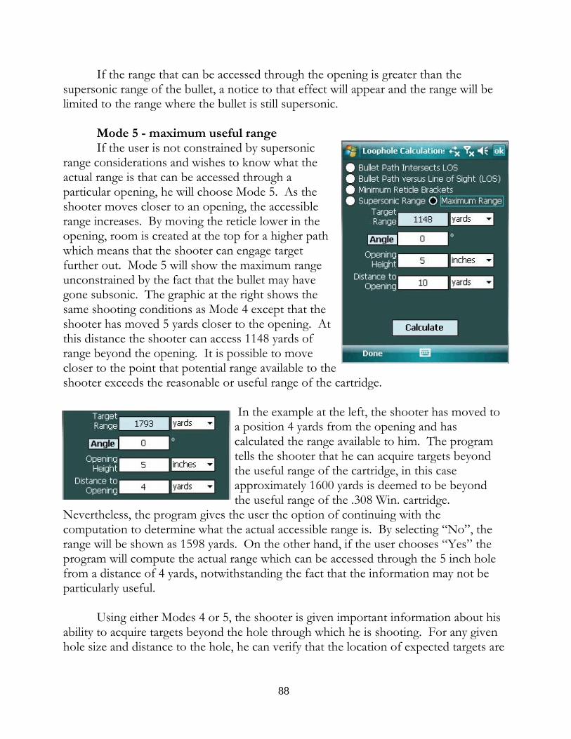
If the range that can be accessed through the opening is greater than thesupersonic range of the bullet, a notice to that effect will appear and the range will belimited to the range where the bullet is still supersonic.
Mode 5 - maximum useful rangeIf the user is not constrained by supersonic
range considerations and wishes to know what theactual range is that can be accessed through aparticular opening, he will choose Mode 5. As theshooter moves closer to an opening, the accessiblerange increases. By moving the reticle lower in theopening, room is created at the top for a higher pathwhich means that the shooter can engage targetfurther out. Mode 5 will show the maximum rangeunconstrained by the fact that the bullet may havegone subsonic. The graphic at the right shows thesame shooting conditions as Mode 4 except that theshooter has moved 5 yards closer to the opening. Atthis distance the shooter can access 1148 yards ofrange beyond the opening. It is possible to movecloser to the point that potential range available to theshooter exceeds the reasonable or useful range of the cartridge.
In the example at the left, the shooter has moved toa position 4 yards from the opening and hascalculated the range available to him. The programtells the shooter that he can acquire targets beyondthe useful range of the cartridge, in this caseapproximately 1600 yards is deemed to be beyondthe useful range of the .308 Win. cartridge.
Nevertheless, the program gives the user the option of continuing with thecomputation to determine what the actual accessible range is. By selecting “No”, therange will be shown as 1598 yards. On the other hand, if the user chooses “Yes” theprogram will compute the actual range which can be accessed through the 5 inch holefrom a distance of 4 yards, notwithstanding the fact that the information may not beparticularly useful.
Using either Modes 4 or 5, the shooter is given important information about hisability to acquire targets beyond the hole through which he is shooting. For any givenhole size and distance to the hole, he can verify that the location of expected targets are
88

within the range zone which his setup will enablehim to cover. For any given range, he can verifythe safe areas to hold through a Mode 3 analysis ashe determines where the bracketed “no-go” areasare in his scope. And, of course, he can verify theactual bullet path for various ranges to ensure asuccessful transit of the opening by the bullet.
Limitation WarningIt bears repeating that while it is possible to
obtain bullet position with respect to LOS out tothe maximum possible range of the bullet, the usershould know that these calculations ignore 1)cross-wind vertical deflection, 2) Coriolis and 3)Eotvos effects. Therefore, these calculations aremeant for practical distances where these small
corrections will not be meaningful.
Path Metrics
The data which can be obtained from this work area gives the shooter importantinformation about the trajectory.
Mode 1 - Maximum OrdinateThe highest point along the trajectory is called the "Maximum Ordinate" and
tells the shooter how far above the line of sight the bullet is expected to travel at itsmaximum point along the trajectory. This information may be important if theshooter is trying to shoot either under or over an obstacle. To be of value, the shootermust know both the maximum height of the bullet and the range at which it occurs. Examples of where this information might be indispensable are numerous: shootingunder a bridge at a target beyond; shooting over high-power electrical power lines toname just two. In addition, the maximum ordinate my help the shooter understandwhat winds might be involved in deflecting the bullet on the way to the target. If, forexample, the shooter is located in an area that has a surface topography that shieldshim from the wind, he can determine whether the trajectory may elevate the bullet outof the protected area and into the wind stream causing a substantial wind deflection,estimate the deflection and modify his point of aim accordingly.
Mode 2 - Danger SpaceThis information tells the shooter, for a target of a given height, how precise the
89
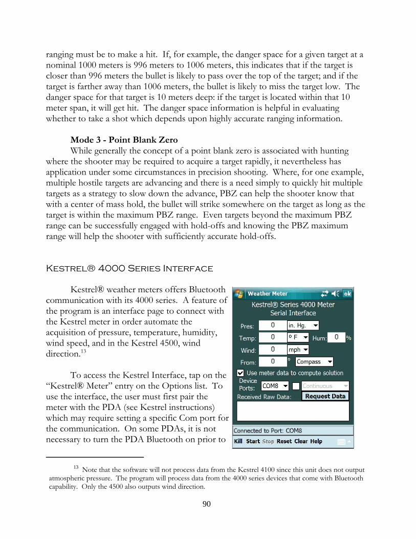
ranging must be to make a hit. If, for example, the danger space for a given target at anominal 1000 meters is 996 meters to 1006 meters, this indicates that if the target iscloser than 996 meters the bullet is likely to pass over the top of the target; and if thetarget is farther away than 1006 meters, the bullet is likely to miss the target low. Thedanger space for that target is 10 meters deep: if the target is located within that 10meter span, it will get hit. The danger space information is helpful in evaluatingwhether to take a shot which depends upon highly accurate ranging information.
Mode 3 - Point Blank ZeroWhile generally the concept of a point blank zero is associated with hunting
where the shooter may be required to acquire a target rapidly, it nevertheless hasapplication under some circumstances in precision shooting. Where, for one example,multiple hostile targets are advancing and there is a need simply to quickly hit multipletargets as a strategy to slow down the advance, PBZ can help the shooter know thatwith a center of mass hold, the bullet will strike somewhere on the target as long as thetarget is within the maximum PBZ range. Even targets beyond the maximum PBZrange can be successfully engaged with hold-offs and knowing the PBZ maximumrange will help the shooter with sufficiently accurate hold-offs.
Kestrel® 4000 Series Interface
Kestrel® weather meters offers Bluetoothcommunication with its 4000 series. A feature ofthe program is an interface page to connect withthe Kestrel meter in order automate theacquisition of pressure, temperature, humidity,wind speed, and in the Kestrel 4500, winddirection.13
To access the Kestrel Interface, tap on the “Kestrel® Meter” entry on the Options list. Touse the interface, the user must first pair themeter with the PDA (see Kestrel instructions)which may require setting a specific Com port forthe communication. On some PDAs, it is notnecessary to turn the PDA Bluetooth on prior to
13 Note that the software will not process data from the Kestrel 4100 since this unit does not outputatmospheric pressure. The program will process data from the 4000 series devices that come with Bluetoothcapability. Only the 4500 also outputs wind direction.
90
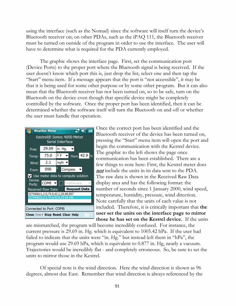
using the interface (such as the Nomad) since the software will itself turn the device’sBluetooth receiver on; on other PDAs, such as the iPAQ 111, the Bluetooth receivermust be turned on outside of the program in order to use the interface. The user willhave to determine what is required for the PDA currently employed.
The graphic shows the interface page. First, set the communication port(Device Ports) to the proper port where the Bluetooth signal is being received. If theuser doesn’t know which port this is, just drop the list, select one and then tap the“Start” menu item. If a message appears that the port is “not accessible”, it may bethat it is being used for some other purpose or by some other program. But it can alsomean that the Bluetooth receiver has not been turned on, so to be safe, turn on theBluetooth on the device even though that specific device might be completelycontrolled by the software. Once the proper port has been identified, then it can bedetermined whether the software itself will turn the Bluetooth on and off or whetherthe user must handle that operation.
Once the correct port has been identified and theBluetooth receiver of the device has been turned on,pressing the “Start” menu item will open the port andbegin the communication with the Kestrel device. The graphic to the left shows the page oncecommunication has been established. There are afew things to note here: First, the Kestrel meter doesnot include the units in its data sent to the PDA. The raw data is shown in the Received Raw Datadisplay area and has the following format: thenumber of seconds since 1 January 2000, wind speed,temperature, humidity, pressure, wind direction. Note carefully that the units of each value is notincluded. Therefore, it is critically important that theuser set the units on the interface page to mirrorthose he has set on the Kestrel device. If the units
are mismatched, the program will become incredibly confused. For instance, thecurrent pressure is 29.69 in. Hg. which is equivalent to 1005.42 hPa. If the user hadfailed to indicate that the units were “in. Hg.” but instead left them in “hPa”, theprogram would use 29.69 hPa, which is equivalent to 0.877 in. Hg, nearly a vacuum. Trajectories would be incredibly flat - and completely erroneous. So, be sure to set theunits to mirror those in the Kestrel.
Of special note is the wind direction. Here the wind direction is shown as 96degrees, almost due East. Remember that wind direction is always referenced by the
91

source of the wind, i.e. the direction it is coming from. Second, note that this directionis identified as “Compass”. This is because the declination value in the Kestrel unit isset to 0 degrees and the value is uncorrected and thus the direction as reported by themagnetic compass. If the user had, for some reason, set the declination to the localvalue, the user would have also set the wind direction reference at “True” because thedeclination will correct the magnetic compass value to the true North reference.14
Once the connection has been established, the user can update the values on theinterface page by either tapping the “Request Data” button or by pressing the Enterbutton on the face of the device. The user will note also that the “Kill” menu item haschanged to “Close” permitting the closure of the interface page without closing theserial port; the data will continue to be received when requested.
Upon “Closing” the interface page the user will note that the wind speed anddirection data areas on the main page have turned a slightly darker background color. This is a visual cue to the user that the Kestrel unit is connected and the port is open. The windage data can be updated by pressing the Enter button on the PDA controlpanel. Likewise, going to the Presets page the user will note that the Pressure,Temperature and Humidity data areas are the same darker background color to visuallycue the user. Those data areas can also be updated by pushing the Enter button whilein the Presets page. The same is true on the Target Range Card as it relates to the windspeed and direction data items.15
This particular port is used to transmit requests to the Kestrel unit and receivethe information in reply. When “Stop[ping]” the data and then re-“Start[ing]” theconnection, allow a couple of seconds to permit the operating system to properly clearthe port and open it. Don’t get in a hurry as it will provoke a “port not accessible”error message. If that message appears, tap the “Reset” menu item a couple of timesand try to open the connection again. If the message persists, check the Kestrel unit tomake sure it is still on. It may have shut off automatically.
14 The program uses the term “magnetic variation” to describe the local value that must be added toor subtracted from the compass value to yield a “True” direction whereas the device documentation uses theterm “declination”. Declination has two components: the magnetic variation (the difference between trueNorth and magnetic North from the current location) plus magnetic deviation (any local cause of magneticdeflection such as high tension wires, electronic equipment, or a magnetic source in the immediate vicinity. The software does not deal with magnetic deviation; the program gives the user, for any given position onEarth, the magnetic variation for that position. Hence the difference in terminology.
15 Not shown on the Kestrel graphics is the addition of a “Omit Wind” check box in version 4.8.1.5. Checking this box will allow the Kestrel data to refresh the pressure, temperature, and humidity but will notaffect the wind value or direction in the main program.
92

Continuous OperationLooking back at the interface page, with the connection “Stop[ped]” or “Reset”,
the check box related to the “Continuous” drop down box becomes enabled. Checking the check box enables the “Continuous” drop down box allowing the user tochoose various update time intervals. The default is two seconds and the user canchoose an interval up to every 1 minute.
Two considerations when using the Continuous mode: first, as long as therequests for data from the Kestrel unit is continuously occurring, the battery is beingdrained on both units. Second, continuous operations interferes with other displayareas, such as the Elevation Table. With each refresh of the data and new computationof the firing solution, the Elevation Table is redrawn and the data presented in itsdefault format. So, if the user is looking at the time of flight column when the requestfor Kestrel data occurs, the user will see the TOF column disappear replaced withupdated computations as if the the “Refreash” menu item had been pressed. Theeffect is basically the same: with each update of Kestrel data, the state of the datathroughout the program’s environment is “refreshed” and set back to default.
Advanced Directory Management
For some users with numerous target, rifle, bullet profiles, it becomes desirableto create subdirectories to hold related groups of profiles. In prior version of thesoftware, this was made nearly impossible due to limitations of the operating system inallowing access to directories or folders below the first level using the defaultOpen/Save dialog box. The most recently release version, however, has replaced thedefault Open/Save dialog box with a custom designed dialog that allows the user tonavigate to and see all existing files and subfolders in a particular folder. This newdialog also allows users to see the file extensions on each file (something the defaultdialog obscures.)
A. Default PathsTo the extent that the user needs to create subdirectories in the standard profile
directories that come with the program. To view this feature, go to the Presets pageand click on “Defaults” in the menu. Initially the default directories are displayed andif the users has not create subdirectories in any of the default directories, those will bethe only directories available. However, assume that the user has segregated target filesinto logical groups. Perhaps the user wants to create subdirectories in FFS_Targeting
93

that will hold targeting files related certain specificareas where the user habitually frequents. Forpurposes of the manual, the example targeting filesAlpha, Bravo, and Charlie, have had subdirectoriescreated with all Alpha related files moved into theAlpha subdirectory, Bravo into the Bravosubdirectory and so forth. The direct targeting fileshave been left in the original directory,FFS_Targeting.
Note that since the various related files havebeen moved into logically named subdirectories, onlythe direct targeting files now show on the target list. In the drop-down FFP list, only “Direct Range”FFPs appear and only corresponding direct targetsare listed. This happens because the program “sees”only the .ffp, .tgt, and .grp files that are presently in FFS_Targeting. The othertargeting files have been moved into subdirectories so as not to be seen when they arenot relevant.
Going to the default paths form, (Presets->Defaults), and tapping on theTargeting drop-down list, the three subdirectories that were created can now be seen.
If subdirectory “Alpha” is chosen, the target list now shows only Alpha FFPs,targets, and, in the Target Range Card, groups.
The reason why this is the case is that as far asthe program is concerned, the new default path to alltargeting files is FFS_Targeting\Alpha and theprogram will look only there for targeting files. IfAlpha happens to be the location where the shooteris going be accessing targets, this is very convenientsince he will not be presented with non-relevanttargets.
The user can, of course, update the targets in the Alpha area by saving additionalAlpha related target in the Alpha subdirectory and those new targets will come to belisted in the Target List.
While the user can change the default path to other profiles, not all changesmake sense. Unless there is a compelling reason to segregate atmosphere profiles, for
94
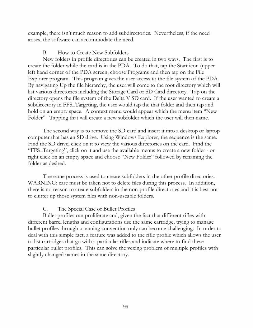
example, there isn’t much reason to add subdirectories. Nevertheless, if the needarises, the software can accommodate the need.
B. How to Create New SubfoldersNew folders in profile directories can be created in two ways. The first is to
create the folder while the card is in the PDA. To do that, tap the Start icon (upperleft hand corner of the PDA screen, choose Programs and then tap on the FileExplorer program. This program gives the user access to the file system of the PDA. By navigating Up the file hierarchy, the user will come to the root directory which willlist various directories including the Storage Card or SD Card directory. Tap on thedirectory opens the file system of the Delta V SD card. If the user wanted to create asubdirectory in FFS_Targeting, the user would tap the that folder and then tap andhold on an empty space. A context menu would appear which the menu item “NewFolder”. Tapping that will create a new subfolder which the user will then name.
The second way is to remove the SD card and insert it into a desktop or laptopcomputer that has an SD drive. Using Windows Explorer, the sequence is the same. Find the SD drive, click on it to view the various directories on the card. Find the“FFS_Targeting”, click on it and use the available menus to create a new folder - orright click on an empty space and choose “New Folder” followed by renaming thefolder as desired.
The same process is used to create subfolders in the other profile directories. WARNING: care must be taken not to delete files during this process. In addition,there is no reason to create subfolders in the non-profile directories and it is best notto clutter up those system files with non-useable folders.
C. The Special Case of Bullet ProfilesBullet profiles can proliferate and, given the fact that different rifles with
different barrel lengths and configurations use the same cartridge, trying to managebullet profiles through a naming convention only can become challenging. In order todeal with this simple fact, a feature was added to the rifle profile which allows the userto list cartridges that go with a particular rifles and indicate where to find theseparticular bullet profiles. This can solve the vexing problem of multiple profiles withslightly changed names in the same directory.
95
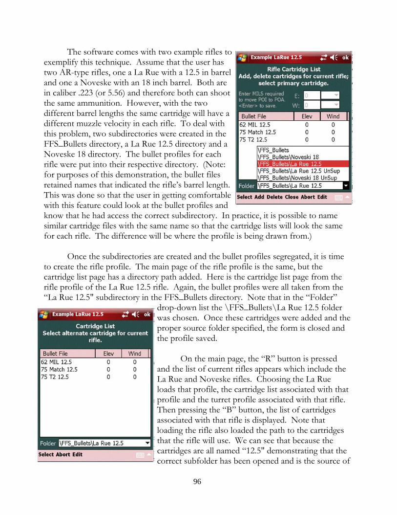
The software comes with two example rifles toexemplify this technique. Assume that the user hastwo AR-type rifles, one a La Rue with a 12.5 in barreland one a Noveske with an 18 inch barrel. Both arein caliber .223 (or 5.56) and therefore both can shootthe same ammunition. However, with the twodifferent barrel lengths the same cartridge will have adifferent muzzle velocity in each rifle. To deal withthis problem, two subdirectories were created in theFFS_Bullets directory, a La Rue 12.5 directory and aNoveske 18 directory. The bullet profiles for eachrifle were put into their respective directory. (Note:for purposes of this demonstration, the bullet filesretained names that indicated the rifle’s barrel length. This was done so that the user in getting comfortablewith this feature could look at the bullet profiles andknow that he had access the correct subdirectory. In practice, it is possible to namesimilar cartridge files with the same name so that the cartridge lists will look the samefor each rifle. The difference will be where the profile is being drawn from.)
Once the subdirectories are created and the bullet profiles segregated, it is timeto create the rifle profile. The main page of the rifle profile is the same, but thecartridge list page has a directory path added. Here is the cartridge list page from therifle profile of the La Rue 12.5 rifle. Again, the bullet profiles were all taken from the“La Rue 12.5" subdirectory in the FFS_Bullets directory. Note that in the “Folder”
drop-down list the \FFS_Bullets\La Rue 12.5 folderwas chosen. Once these cartridges were added and theproper source folder specified, the form is closed andthe profile saved.
On the main page, the “R” button is pressedand the list of current rifles appears which include theLa Rue and Noveske rifles. Choosing the La Rueloads that profile, the cartridge list associated with thatprofile and the turret profile associated with that rifle. Then pressing the “B” button, the list of cartridgesassociated with that rifle is displayed. Note thatloading the rifle also loaded the path to the cartridgesthat the rifle will use. We can see that because thecartridges are all named “12.5" demonstrating that thecorrect subfolder has been opened and is the source of
96

the cartridges. If the “62 Mil 12.5" cartridge is double tapped, it loads and will havethe proper muzzle velocity for the 12.5" barreled La Rue. Observe also that near thebottom of the form there is a reference to the directory which is the source of thebullet profiles. This is to assure the shooter that the correct folder is being accessed.
The reader may have noticed that there are two other subfolders in FFS_Bullets:the La Rue 12.5 UnSup and the Noveske 18 UnSup. The various bullet profilescreated for the La Rue and Noveske have muzzle velocity data relating to theirnormally suppressed condition. When thesuppressor is removed, two potentialities may occur. First, there may be a change in muzzle velocity. Second, there may be a change in the point ofimpact. To deal with these, two Offest profiles werecreated and their respective cartridge lists will 1)draw from their respective subdirectory so that anychange in muzzle velocity can loaded when thecartridge is loaded; and, 2) each cartridge is given anoffset to bring the point of impact back to the pointof aim. This saves the operator from having toadjust the scope’s zero. Here is the cartridge listfrom the La Rue 12.5 Offset profile, called the “LaRue 12.5 UnSup”. These related offset profiles canbe access by tapping the “O” button on the mainpage. The reader will also see a “La Rue 12.5 CCB”offset file which contains offset for the cold, cleanbore shot(s). Tap and holding on the La Rue 12.5 UnSup entry will bring up a contextmenu. Choosing “Edit” will open the offset profile in the profile editor and tapping“Add” will open the cartridge list. Here the cartridges are already added. Note thatthe names confirm that the cartridges were drawn from the correct subfolder and thefolder path correctly lists the path to that folder.
Because rifle profiles come with a path to their respective cartridges, it is notnecessary to change anything in the default paths form. If a rifle profile does not havea cartridge list of if the number of rifles/cartridges are not so numerous to warrantsegregation, then the profile will use the default FFS_Bullets to find its cartridges andno further folder additions are required. In fact, the entire use of subfolders and thechanging of default paths is optional. The program does not require this level ofcomplexity to function.
97

Export/Import of Targeting Files
Targeting files can be exported and imported by going to Profiles->Targeting->Export/Import. The export function is rather limited in that it converts targetingfiles into a .wpt file which is usable by OziExplorer GPS software and Google Earth. For Google Earth use, simply start Google Earth and then drag and drop the .wpt filesonto the Earth. It will slew to the location and show the various files at theirrespective coordinate locations.
To use the tool, first, go to the Setup page to identify the paths to the files toexport and where these exported files are to be placed. Do a similar identification forimport locations. In both cases it is likely that the export source and importdestination will be FFS_Targeting, but it is possible to specify other folders if desired.
Back on the main Export/Import page, tap the Export (or Import) button andfind the files to operate on via the Open File dialog. Once chosen, the file willimmediately be converted and a message will be displayed concerning the newexported file. When all of the files have been exported, use the File Explorer to openthe folder where the exported files are located. At this point, the files are ready to becopied, moved, or otherwise used in other applications which can open and read .wptfiles. Importing is a similar process.
Using the Expression Calculator
Version 4.8.1.4 introduced an advanced calculator, one that could store userdefined formulas using up to two variables and that could parse expressions. Wherethe expression is comprised of numbers only, the “x” and “y” variable text input areasdo not have meaning or functionality. The arithmetic expression will be parsed andthe result will be given in the answer text area. The value of using an expression parserinstead of the simple calculator is that the entire expression remains on the screen sothe user can see and modify, if necessary, the expression before it is evaluated. Andonce evaluated the expression remains on the screen so that the user can makemodifications if the result does not make sense. For example, 5 + 10 / 5 will produce7 and not 3 as some might suppose. The reason has to do with the precedence ofoperations. In this case, the calculator sees the 5 dividing only the 10 and not the sumof 5 + 10. It is best to use parentheses to clarify the expression: (5 + 10) / 5. This willresolve to the answer 3, i.e., 15/5 = 3. Thus the user can edit the expression instead ofhaving to enter the expression from scratch.
In addition, the calculator can evaluate equations with up to two variables.
98

Example: the hypotenuse of a right triangle can be found by taking the square root ofthe sum of the squares of the other two sides. So if the user were to type into theexpression text area “sqrt( a^2 + b^2)” as a general statement, the user would see thevariables “a” and “b” immediately appear next to the two variable input text areas. There is where the user gives the values for “a” and “b”. If, for example, “a” isassigned the value of 3 and “b” is assigned a value of 4, pressing the “=” key willproduce the answer of 5. The formula remains in the expression area so the user canmake changes or introduce new variable values.
The variable text areas are themselves capable of handling expressions. Thevariable “a” could be “7.3 * sqrt (7)”. Tapping the “Eval” button while the cursorremains in the “a” text area will show what the “a” arithmetic expression evaluates to,in this case 19.3139... It is not necessary to evaluate the variable expression prior touse in the equation, but it is a way to see whether the evaluation makes sense orwhether perhaps a mistake was made. Since the evaluated variable expression replacesthe original expression, in the event of an apparent error, the user will have to re-typethe expression.
A. Storing User Defined FormulasAt the far right of the Expression text area is a drop-down arrow. The software
comes with some example formulas so the user can how to access the formulas thatthe user might make for himself. The formulas themselves are taken from a text filethat can be edited by the user. The existing formulas can be deleted and replaced byformulas that are useful to the user. To access this text file, tap the “Help” menu itemand then select “Edit Formulas”. For the first time user, read the text in this file as itexplains how to edit the file. Note that lines that start with the semi-colon symbol areignored by the calculator. These lines are for explaining the purpose or use of aformula or other matter the user wants to memorialize. After the explanation has beread and understood, the user is free to delete the explanation.
Next comes the formulas themselves followed by a short explanation that startswith a semi-colon. When the calculator program read through this text file, anyformulas that it finds will be copied to the drop-down menu and the explanation thatfollows will be place immediately below the formula to help the user to rememberwhat the variables are and what units they should be in (if required.) One of theformulas is to compute the cross-wind component of an angling wind. The formula iscross-wind = wind velocity * sin(wind angle relative to shooter), or “w * sin(a)” willproduce the cross-wind component. So, assuming a 7 mph wind from the shooter’s 1o’clock, the formula is w * sin(a) and the variables are w = 7, a = 30 degrees (1 o’clockis 30 degrees, 2 o’clock is 60 degrees, and 3 o’clock is 90 degrees.) Putting those valuesinto the two variable text areas and tapping “=” will yield 3.5 mph in the answer text
99

area. If the wind speed was 7 m/s or 7 fps, then the answer would be 3.5 m/s or 3.5fps.
There is not a lot of room for the one line explanation of the formula, but in thetext file the user can add as much detail as required. Just make sure that the allexplanatory text begins with a “;”.
Updating Delta V Software
A. Versions 4.7 and EarlierEach of these program has a unique “fingerprint” which manifests itself through
a set of data that must be reproduced by the user in order to purchase updates. Updates are obtained via the Lex Talus Corporation’s website by choosing the updaterequired and proceeding through the purchase process. In the initial window whichdisplays the shopping cart, there is a text area for the user to input the required data sothat Lex Talus can create the updated software for the user that will be compatiblewith the SD card the user already owns. At the time of purchase, Lex Talus salesdepartment receives a notice of sale which includes the unique data from the user, usesthis data to create the necessary software and emails the updated software to the user. The updated software is installed on the SD card via an updating/installer programthat runs on a Windows desktop computer and automates the updating process. Atthe conclusion of running the updating program, the update is complete.
In order for the user to obtain the necessary program information, open theOptions->About->Program Info form and click on the “Get Program Identifiers”button. This creates a text file (the content of which is shown in the text window onthe form) which is saved in the \Documents directory of the SD card. Simply copythe text file to the desktop computer, open the file and copy the content, and thenpaste it into the text window of the shopping cart during the purchase process. Alternatively, complete the update purchase and email the text file to Lex Talus sales([email protected]) notifying Lex Talus of the purchase and relating the data to thepurchase. In this case, it would be prudent to indicate in the shopping cart text formthat the program data is being sent separately via email.
B. Version 4.8With version 4.8 an effort was made to make the update process much easier.
For version 4.8 installed software the update process consists of merely checking thewebsite’s Delta V page and noting the current update version number. A link isprovided on that page to download the instructions for update and the instructionscontain a link to a download site. Download the current version and install inaccordance with the instructions. The program identifiers mentioned in the preceding
100
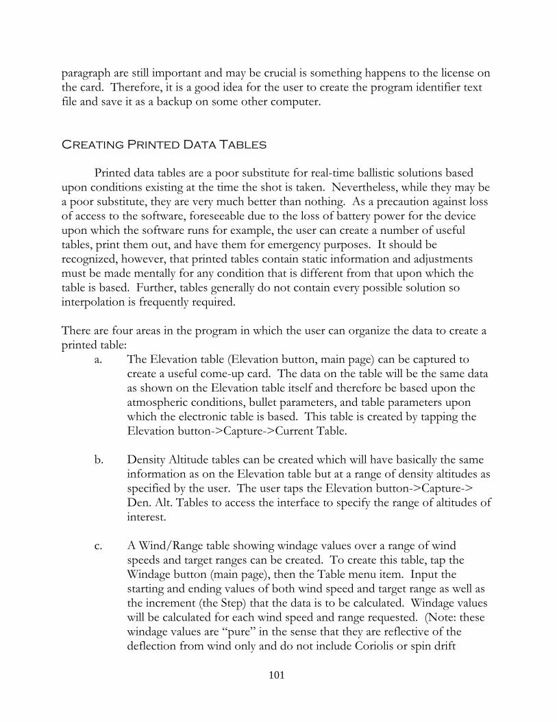
paragraph are still important and may be crucial is something happens to the license onthe card. Therefore, it is a good idea for the user to create the program identifier textfile and save it as a backup on some other computer.
Creating Printed Data Tables
Printed data tables are a poor substitute for real-time ballistic solutions basedupon conditions existing at the time the shot is taken. Nevertheless, while they may bea poor substitute, they are very much better than nothing. As a precaution against lossof access to the software, foreseeable due to the loss of battery power for the deviceupon which the software runs for example, the user can create a number of usefultables, print them out, and have them for emergency purposes. It should berecognized, however, that printed tables contain static information and adjustmentsmust be made mentally for any condition that is different from that upon which thetable is based. Further, tables generally do not contain every possible solution sointerpolation is frequently required.
There are four areas in the program in which the user can organize the data to create aprinted table:
a. The Elevation table (Elevation button, main page) can be captured tocreate a useful come-up card. The data on the table will be the same dataas shown on the Elevation table itself and therefore be based upon theatmospheric conditions, bullet parameters, and table parameters uponwhich the electronic table is based. This table is created by tapping theElevation button->Capture->Current Table.
b. Density Altitude tables can be created which will have basically the sameinformation as on the Elevation table but at a range of density altitudes asspecified by the user. The user taps the Elevation button->Capture->Den. Alt. Tables to access the interface to specify the range of altitudes ofinterest.
c. A Wind/Range table showing windage values over a range of windspeeds and target ranges can be created. To create this table, tap theWindage button (main page), then the Table menu item. Input thestarting and ending values of both wind speed and target range as well asthe increment (the Step) that the data is to be calculated. Windage valueswill be calculated for each wind speed and range requested. (Note: thesewindage values are “pure” in the sense that they are reflective of thedeflection from wind only and do not include Coriolis or spin drift
101
deflections even if those elements are options included by the user in thenormal firing solution calculation.)
d. A reticle ranging table is available for creation which correlates target sizeand reticle measurement to obtain the range to target. This table iscreated by tapping Ranging->Reticle->Table and specifying the range oftarget heights and reticle measurements of interest.
Each table created will be found in the \Documents folder on the SD card andeach will be in the format of a “CSV” file (Comma Separated Values). This is a textfile that can be directly read by most spreadsheets which will organize the data items inrows and columns to create the table. The resulting table will not be pretty; CSV filescannot specify how the data is to look, how it is to be formatted in the cell, or whatcolor or font should be used. It is just the plain, basic, numbers laid out as arudimentary table. But the hard work of gathering perhaps hundreds of solutions hasbeen done and what remains is making the data look nice and readable. This step willdepend upon the skill the user has developed with spreadsheets.
In order to permit a single file to contain multiple tables varying in the range ofthe input values or based upon different atmospheric conditions or even differentbullets, etc., the program will append a new table to the data already in an existing file. For example, if the user wanted to create windage tables for different density altitudes,but all covering the same range of values, he would go into the Presets page andchoose atmospheric conditions that would yield a particular density altitude, Accept,and then open the table interface page in the Windage section. He would input thewind and range parameters, create the table, and then go back to Presents to input thenext density altitude condition. This would be repeated until the entire range ofdensity altitudes had resulting tables. When he opens the single “Windage Table.csv” file in a spreadsheet program, he would find all of the tables he had built, one for eachdensity altitude he specified. He would then work with the spreadsheet program toformat, color, and arrange these tables to his satisfaction, print them out, and havethem as emergency reference material in the event the ballistic software wasunavailable. If the user wanted to save the data file and not permit further appending,he would simply change the name or move it out of the \Documents folder. The nexttime he created a windage table, a new “Windage Table.csv” file would be created.
102

FAQ and Troubleshooting
1. GPS and WM 5.0 and 6.0 Issues
When plugging a GPS into a serial port, on WM 2003 SE and before, theprogram will automatically search for and lock on the signal. Starting with WM 5.0,however, Microsoft included some GPS tools for the user and the tools may interferewith the automatic search feature. For WM 5.0 users, go to “Start”, “Settings” andchoose the “System” tab. The click on the GPS icon. On “Programs” and“Hardware” tab, choose “None” and on the “Access” tab check the “Manage GPSAutomatically” box. Depending upon the quality of the GPS unit, it may take manyminutes for the GPS to start working correctly.
2. Program malfunctions on startup
Sometimes a user will create a profile with data that the program can’t read. Sometimes a user will omit data that the program expects to read from the profile. Inthese cases, particularly with erroneously constructed turret profiles (and particularly inthe construction of the turret/click number pairs), the program may issue a errormessage and cease functioning. Worse, when the user starts the program again, theerror persists making the program unusable.
First, if the program has trouble with a profile, suspect that it contains improperdata or has become corrupt and stop using it. Create another profile from scratch. Ifyou have problems or questions, contact [email protected] with your questions. You can attach the problem profile to the email for us to look at.
Second, understand that when the program closes it writes all current data to afile called “eSession” located in the Program Files folder on the SD card. Sometimeswhen an errant profile has been opened, should the program crash, the data is stillsaved including the name of the profile that was just opened. When the user runs theprogram again, the program looks in the eSession file and begins to load all of thesaved data and may try to open the profile that caused the problem in the first place.
Therefore, if the program is malfunctioning and continues to malfunction uponstartup, go to the Program Files folder on the SD card and delete the eSession file. The program will then start using all default values.
103
3. Trouble building Turret Profiles
If you are having a problem building a turret profile on the PDA, open anexample turret profile to see how it was built, particularly the turret number pairs. Youcan also change existing numbers to those representing your particular scope and then“Save As” a new scope profile. Examples have been provided for single (or double)turn, BDC, and multi-rev turrets.
If you have a two turn turret you should create it as you would a single turnturret. Most two turn turrets have cardinal numbers that simply continue using a two-tier numbering system. So, start with the number zero with zero clicks and continuesequentially with the numbering scheme matching each number with the total numberof clicks it takes to get to the number from zero. (Example: for a 1/4 MOA per clickturret with cardinal numbers every 2 MOA, the turret numbering will be 0, 2, 4, 6, etc.while the corresponding click values will be 0, 8, 16, 24, etc.)
4. You insert the SD card into your PDA but the program doesn’t runa. Is .NET Compact Framework 2.0 installed? Although all versions ofWindows Mobile 6.0 and later came with .NET Compact Framework 2.0 orbetter, some PDAs with Windows Mobile 5.0 didn’t and this support softwareneeds to be installed. So, download and install .NET Compact Framework. There is a link to it on the website in the Support area. Be sure to get any andall Service Packs.
b. If the foregoing does not solve the problem, it is possible that the operatingsystem has become corrupt. First do a soft reset. If that fails, do a hard reset. Before taking this last action backup your data since a hard reset will reset thePDA to its original factory condition and all additional programs, files and datawill be gone.
5. Why is my zero range not showing exactly zero for elevation?Check your Options and see if you have “Vertical Deflection” selected. If so,
with a cross-wind there will be a slight vertical deflection that will be shown at the zerorange. Also deselect the “Coriolis/Eötvös” option. A shot bearing other than Northor South will produce a small vertical component.
6, Backing Up the DataYou may backup any and all files on the card EXCEPT the \2577 folder.
Backing up and restoring this folder will break the program and necessitate the returnof the card to Lex Talus for repair at the owner’s expense.
104

Functional Outline
As an aid to quickly understanding the functionality of the Delta V software, thefollowing presentation arranges the features in four data groups: User preferences, coreinputs, refinements and support tools.
1. User Preferencesa. English v. Metric (Options menu)
b. English units, but Range in meters (Options menu)
c. MIL v. MOA units (Options menu)
d. Degrees v. Cosine (Options menu)
e. Use Turret Windage (Options menu)
f. Degrees v. Clock for wind direction (Main page)
g. Station v. barometric pressure (Presets page)
2. Core Inputs - the five basic data setsa. Atmosphere
i. Pressure, temperature, humidity (Presets page)
b. Bulleti. Caliber, weight, muzzle velocity, ballistic coefficient (Presets page)
c. Scopei. Zero, height above bore (Presents page)
d. Targeti. Range, angle, speed, heading (Main page)
e. Windi. Speed, origin (Main page)
3. Refinementsa. Multi-zones (Wind page)
b. Spin Drift (Options menu)
APPENDIX Page 1

c. Powder Temperature (Options menu)
d. Cross-wind Vertical deflection (Options menu)
e. Coriolis Acceleration (Options menu)
f. Correcting for magnetic variation (Options menu)
4. Support Toolsa. Wind
i. Estimating wind at distance (Wind page)
b. Target Range Cardi. FFP/Target list with firing solutions
c. Target Table (Targets page)(1) Direct(2) Position Ranging using coordinates
d. Elevation Table (Elevation page)i. Quick velocity referenceii. Vertical holdsiii. Wind holds
e. Windage Table (Windage page)i. Mil or MOA holds for extended values
f. Field Zero (Options menu)
g. Calculator (Options menu)
h. DK calculator (Options menu)
i. MV calculator (Options menu)i. Chronographii. POI Method
j. Profiles (Profiles menu)i. Atmosphere
APPENDIX Page 2

ii. Bullet
iii. Offsets
iv. Rifle
v. Solution
vi. Turret
k. Shot Log (Profiles menu)i. One click per shot log entry
ii. Log editor
l. Ranging (Ranging menu)i. Direct - using rangefinder
ii. GPS
iii. Map(1) Rangefinder - Coordinate calculation
iv. Rangefinder - serial connection to import data
v. Reticle
m. Miscellaneousi. Profile Summary (Main page)
(1) Reference sections
ii. Bullet and Cartridge database (Profiles menu)
iii. Visual Cues(1) Bearing (Coriolis)(2) GPS button(3) Muzzle Velocity - temperature adjusted (Presets)(4) Data access button text fields(5) Subsonic bullet velocity
APPENDIX Page 3
FILE NAMING CONVENTIONS
A. Bullet ProfilesAt a minimum bullet profiles will need a caliber, maker, weight, and some
identifier indicating which rifle it is designed for or some other unique identifier todistinguish it from other loads using similar components. For instance, a bullet profilefor Federal .308 Match will show different muzzle velocities depending upon which riflethe cartridge is going to be used in. Or there may be different loads using the samepowder and bullet but using different primers and resulting in different muzzlevelocities for the same rifle. One convention would be something like:[caliber].[manufacturer].[bullet weight].[rifle/barrel length/unique identifier]
For Federal .308 Match the file name would look like:30.FM175.990
where the 30 is the caliber, the “FM” is for Federal Match, 175 is the bullet weight andthe “990" could be the last few digits of the rifle’s serial number for which this profilewas designed. The muzzle velocity listed in the profile would be for rifle “990". Another .308 Win. might need a different profile if the muzzle velocity of Federal .308Match in that rifle is different from that of rifle “990.”
B. Rifle ProfilesThese profiles include links to a bullet profile and a turret profile. In rifles that
shoot various loads comprising different bullet weights, various bullets from differentmanufacturers or various powder weights, primers or cases. If you plan to shoot thesame rifle using different loads, add each load/cartridge into the cartridge list andhandle any change of POI by using the elevation/windage offsets. You will need onlyone rifle profile per shooter. One format could be as follows;[caliber/model].[rifle/unique identifier/owner initials] or, 30.Rem.jr. Or, for a militaryrifle, M40.jr meaning the M40 issued to “jr”.
C. Offset ProfilesThese profiles relate to a particular rifle, a particular shooter and a particular
position or rifle configuration. The file can actually have the same name as the linkedrifle plus a designator for the position or configuration: [rifle profile name].[position]. So, for example, an offset for the above rifle shooting Federal Match off a bipod mightlook like “M40.jr.bi” and an offset file for the same rifle but shooting off a pack mightlook like “M40.jr.p”. In either case, each of the cartridges listed or associated with thatprofile can have its own offsets for that position. The cartridge list associated with arifle as listed in an Offset Profile need not be the same cartridge list associated with thesame rifle in its own cartridge list. This means that an offset profile can be created for agiven rifle to handle the effects of adding a suppressor; or, if the rifle will be expected to
APPENDIX Page 4

shoot subsonic ammunition, an Offset Profile can be created that contain only subsoniccartridges and the effects that need be recorded to maintain the same scope zero as withsupersonic ammunition.
The application of Offset Profiles is limited only by the users imagination.
APPENDIX Page 5