field evaluation and management of non-battle related knee and
TRANSCRIPT
Journal of Special Operations Medicine Volume 9, Edition 2 / Spring 092
KNEE LIGAMENT TAPINGKnee taping is a good tool for the ATP to have
in his rucksack treatment categories. By using stan-dard adhesive tape applied directly to the skin, or byusing duct tape, it is possible to tape the knee so that theknee and the damaged ligaments are supported. In ad-dition, the taping will also restrict the motion of theknee joint.
Prior to taping, the type and area of damagemust be identified as to whether it is a patellar disloca-tion, torn cartilage, torn medial collateral ligament, tornlateral collateral ligament, or torn anterior cruciate lig-ament. Once the area of the injury is identified, theskin is cleaned to remove any underlying dirt or debris.With the skin dry, the tape may be applied directly tothe skin.
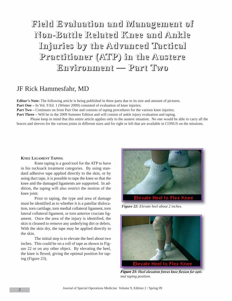
The initial step is to elevate the heel about twoinches. This could be on a roll of tape as shown in Fig-ure 22 or on any other object. By elevating the heel,the knee is flexed, giving the optimal position for tap-ing (Figure 23).
FFFFiiii eeee lllldddd EEEEvvvvaaaalllluuuuaaaatttt iiiioooonnnn aaaannnndddd MMMMaaaannnnaaaaggggeeeemmmmeeeennnntttt oooo ffff NNNNoooonnnn----BBBBaaaatttt tttt llll eeee RRRReeee llllaaaatttteeeedddd KKKKnnnneeeeeeee aaaannnndddd AAAAnnnnkkkkllll eeee IIIInnnnjjjjuuuurrrr iiii eeeessss bbbbyyyy tttthhhheeee AAAAddddvvvvaaaannnncccceeeedddd TTTTaaaacccctttt iiii ccccaaaa llll PPPPrrrraaaacccctttt iiii tttt iiiioooonnnneeeerrrr ((((AAAATTTTPPPP)))) iiiinnnn tttthhhheeee AAAAuuuussss tttteeeerrrreeee
EEEEnnnnvvvviiii rrrroooonnnnmmmmeeeennnntttt — PPPPaaaarrrrtttt TTTTwwwwoooo
JF Rick Hammesfahr, MDEditor’s Note: The following article is being published in three parts due to its size and amount of pictures. Part One – In Vol. 9 Ed. 1 (Winter 2009) consisted of evaluation of knee injuries; Part Two – Continues on from Part One and consists of taping procedures for the various knee injuries;Part Three –Will be in the 2009 Summer Edition and will consist of ankle injury evaluation and taping.
Please keep in mind that this entire article applies only to the austere situation. No one would be able to carry all thebraces and sleeves for the various joints in different sizes and for right or left that are available in CONUS on the missions.
Figure 22: Elevate heel about 2 inches.
Figure 23: Heel elevation forces knee flexion for opti-mal taping position.
Field Evaluation and Management of Non-Battle Related Knee and Ankle Injuries by the Advanced Tactical Practitioner(ATP) in the Austere Environment — Part Two
3
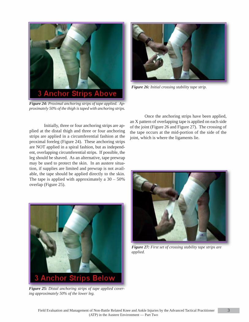
Initially, three or four anchoring strips are ap-plied at the distal thigh and three or four anchoringstrips are applied in a circumferential fashion at theproximal foreleg (Figure 24). These anchoring stripsare NOT applied in a spiral fashion, but as independ-ent, overlapping circumferential strips. If possible, theleg should be shaved. As an alternative, tape prewrapmay be used to protect the skin. In an austere situa-tion, if supplies are limited and prewrap is not avail-able, the tape should be applied directly to the skin.The tape is applied with approximately a 30 – 50%overlap (Figure 25).
Once the anchoring strips have been applied,an X pattern of overlapping tape is applied on each sideof the joint (Figure 26 and Figure 27). The crossing ofthe tape occurs at the mid-portion of the side of thejoint, which is where the ligaments lie.
Figure 24: Proximal anchoring strips of tape applied. Ap-proximately 50% of the thigh is taped with anchoring strips.
Figure 25: Distal anchoring strips of tape applied cover-ing approximately 50% of the lower leg.
Figure 26: Initial crossing stability tape strip.
Figure 27: First set of crossing stability tape strips are applied.

Journal of Special Operations Medicine Volume 9, Edition 2 / Spring 094
This is then reinforced with a second set ofcrossing tape strips (Figures 28 and 29).
Figure 30: Vertical reinforcing strip which further anchorsthe central X of tape.
Figure 28: Application of 2nd set of crossing tape strips.
Figure 29: Final crossing strip applied.
Figure 31: Same crossing tape applied toopposite of the knee, centered at the mid-joint line.
Once a double layer of crossing tape strips hasbeen applied, a final single vertical strip is applied(Figure 30).
Once the strips are applied on one side of thejoint, similar taping is done on the opposite side of thejoint (Figure 31).

Field Evaluation and Management of Non-Battle Related Knee and Ankle Injuries by the Advanced Tactical Practitioner(ATP) in the Austere Environment — Part Two
5
Once both sides have the X-crossed tapes ap-plied along with the vertical reinforcing strip, more cir-cumferential anchoring strips are applied to anchor themedial and lateral X-crossed strips (Figures 32 and 33).
During the process of taping, it is important torecognize that the popliteal fossa (posterior aspect ofthe joint) must be left open to prevent the developmentof tape blisters (Figure 34).
In addition, the kneecap must be left open toallow normal superior and inferior glide motion (Fig-ure 33). This taping technique will provide rotationalstability as well as stability against varus and valgusforces. In addition, flexion and extension will also besomewhat limited.
MENSICUSWhen checking for a torn meniscus, it is nec-
essary to palpate the medial and lateral joint lines fortenderness. A McMurray’s test is then performed. Themedial McMurray’s test (Figure 35) is performed byforcibly flexing the knee and palpating the posterome-dial joint line (to check the medial meniscus) with onehand. With the other hand, grasp the foot and exter-nally rotate the leg at the hip and apply a varus force atthe knee (compressing the medial side of the femur andtibia against the medial meniscus) and extend the knee.If there is a torn meniscus, a click may be felt or heard,and the test is usually painful if there is a damaged me-dial meniscus.
Figure 32: Proximal circumferential anchoring strips appliedproximal to the joint.
Figure 33: Distal circumferential anchoring strips applied.
Figure 34: Popliteal fossa left open to allow for flexion andextension, minimizing the probability of development of skinblisters beneath the tape as the knee moves.

Journal of Special Operations Medicine Volume 9, Edition 2 / Spring 096
In a similar fashion, the lateral McMurray’s test(Figure 36) compresses the lateral side of the femur andtibia together and will pinch the lateral meniscus. Thelateral McMurray’s test is performed by placing onehand on the posterolateral joint line, grasping the footwith the other hand, forcibly flexing the knee, internallyrotating the hip thus producing a valgus force at the kneejoint (which compresses the lateral meniscus betweenthe femur and the tibia) and extending the knee. If themeniscus is damaged, this will cause pain; but if themeniscus is normal, this will not cause pain.
When a person has a torn meniscus, this meansthat the C-shaped piece of fibro-cartilage known as themeniscal cartilage is torn and that this piece of tissuemay displace inside the joint. Often it is a semi-attachedfree fragment much like the balloon on a string. As thisfragment moves around, the fragment may go frombeing in an intra-articular position (Figure 37), but nottrapped between the bones (which is a relatively painlesssituation), to moving to where the meniscal fragment be-comes trapped between the bones (Figure 38). Whenthe torn meniscal fragment becomes trapped betweenthe bones, there will be the loss of extension, and in-creased pain. In addition, the knee may develop an ef-fusion.
Figure 36: Apply a valgus force to compress the lateral tibiaand femur, compressing the lateral meniscus.
Figure 35: Apply a varus force to compress the medial tibiaand femur, compressing the medial meniscus.
Figure 37: Fragment of the medial meniscus trapped in themedial gutter of the knee, adjacent to the medial femoralcondyle. Black circle surrounds the meniscal fragment.
Field Evaluation and Management of Non-Battle Related Knee and Ankle Injuries by the Advanced Tactical Practitioner(ATP) in the Austere Environment — Part Two
7
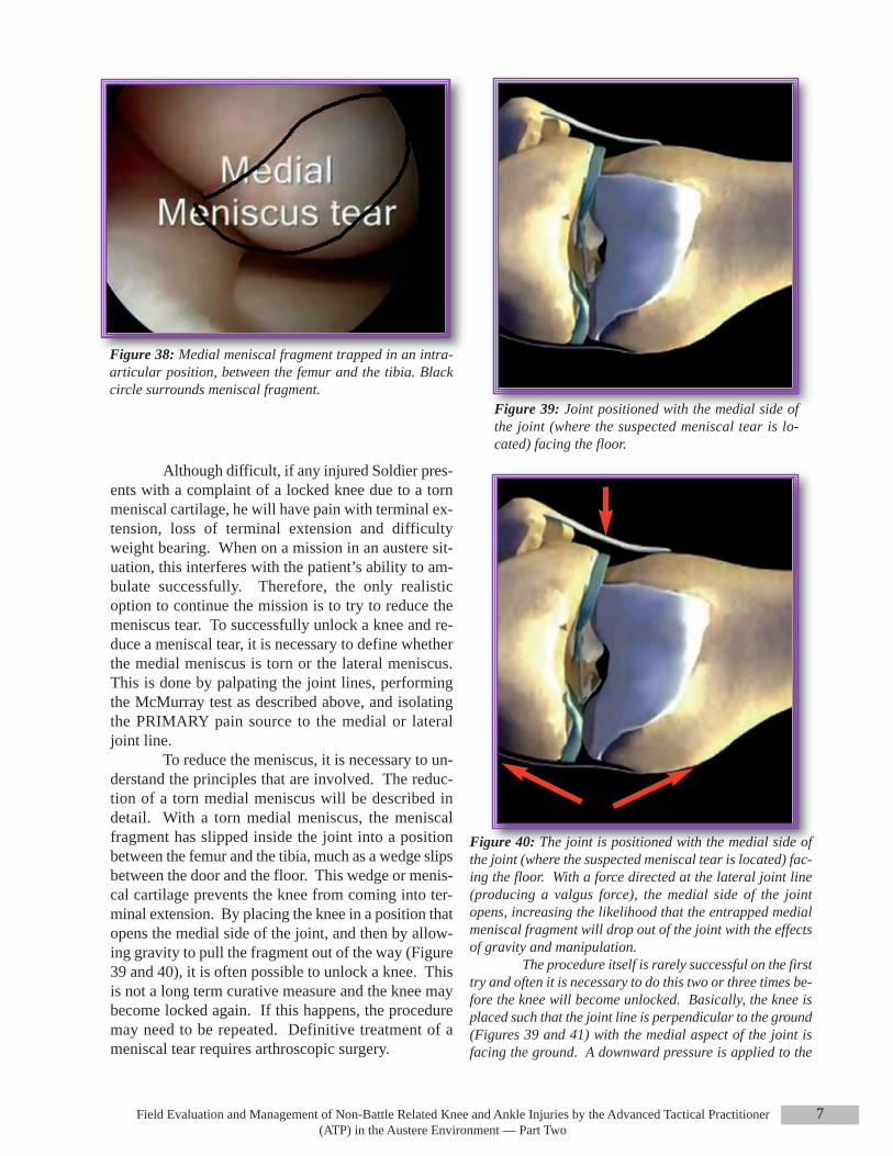
Figure 38: Medial meniscal fragment trapped in an intra-articular position, between the femur and the tibia. Blackcircle surrounds meniscal fragment.
Figure 39: Joint positioned with the medial side ofthe joint (where the suspected meniscal tear is lo-cated) facing the floor.
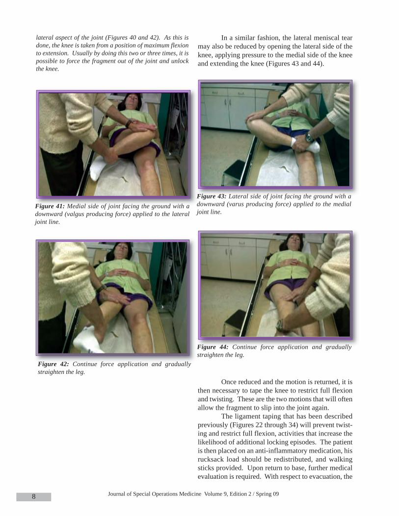
Figure 40: The joint is positioned with the medial side ofthe joint (where the suspected meniscal tear is located) fac-ing the floor. With a force directed at the lateral joint line(producing a valgus force), the medial side of the jointopens, increasing the likelihood that the entrapped medialmeniscal fragment will drop out of the joint with the effectsof gravity and manipulation.
The procedure itself is rarely successful on the firsttry and often it is necessary to do this two or three times be-fore the knee will become unlocked. Basically, the knee isplaced such that the joint line is perpendicular to the ground(Figures 39 and 41) with the medial aspect of the joint isfacing the ground. A downward pressure is applied to the
Although difficult, if any injured Soldier pres-ents with a complaint of a locked knee due to a tornmeniscal cartilage, he will have pain with terminal ex-tension, loss of terminal extension and difficultyweight bearing. When on a mission in an austere sit-uation, this interferes with the patient’s ability to am-bulate successfully. Therefore, the only realisticoption to continue the mission is to try to reduce themeniscus tear. To successfully unlock a knee and re-duce a meniscal tear, it is necessary to define whetherthe medial meniscus is torn or the lateral meniscus.This is done by palpating the joint lines, performingthe McMurray test as described above, and isolatingthe PRIMARY pain source to the medial or lateraljoint line.
To reduce the meniscus, it is necessary to un-derstand the principles that are involved. The reduc-tion of a torn medial meniscus will be described indetail. With a torn medial meniscus, the meniscalfragment has slipped inside the joint into a positionbetween the femur and the tibia, much as a wedge slipsbetween the door and the floor. This wedge or menis-cal cartilage prevents the knee from coming into ter-minal extension. By placing the knee in a position thatopens the medial side of the joint, and then by allow-ing gravity to pull the fragment out of the way (Figure39 and 40), it is often possible to unlock a knee. Thisis not a long term curative measure and the knee maybecome locked again. If this happens, the proceduremay need to be repeated. Definitive treatment of ameniscal tear requires arthroscopic surgery.
Journal of Special Operations Medicine Volume 9, Edition 2 / Spring 098
In a similar fashion, the lateral meniscal tearmay also be reduced by opening the lateral side of theknee, applying pressure to the medial side of the kneeand extending the knee (Figures 43 and 44).
Once reduced and the motion is returned, it isthen necessary to tape the knee to restrict full flexionand twisting. These are the two motions that will oftenallow the fragment to slip into the joint again.
The ligament taping that has been describedpreviously (Figures 22 through 34) will prevent twist-ing and restrict full flexion, activities that increase thelikelihood of additional locking episodes. The patientis then placed on an anti-inflammatory medication, hisrucksack load should be redistributed, and walkingsticks provided. Upon return to base, further medicalevaluation is required. With respect to evacuation, the
Figure 42: Continue force application and graduallystraighten the leg.
Figure 41: Medial side of joint facing the ground with adownward (valgus producing force) applied to the lateraljoint line.
lateral aspect of the joint (Figures 40 and 42). As this isdone, the knee is taken from a position of maximum flexionto extension. Usually by doing this two or three times, it ispossible to force the fragment out of the joint and unlockthe knee.
Figure 44: Continue force application and graduallystraighten the leg.
Figure 43: Lateral side of joint facing the ground with adownward (varus producing force) applied to the medialjoint line.
Field Evaluation and Management of Non-Battle Related Knee and Ankle Injuries by the Advanced Tactical Practitioner(ATP) in the Austere Environment — Part Two
9
healthcare provider should discuss the mission re-quirements with the teamleader. If the Soldier can bemade functional and is able to continue walking andweight bearing, then the probability of mission com-pletion is certainly greater. However, if the ATP is un-able to unlock the knee, then it is unlikely that thepatient will be able to remain functional.
Keep in mind that a previously locked knee,which has been successfully unlocked, may again be-come locked if significant physical demands continueto be placed upon the knee. There may be no advancewarning of subsequent locking episodes, consider thiswhen allowing an Operator to return or continue themission.
Patella DislocationPatellar dislocations typically occur with a
twisting injury or a blow to the medial aspect of thepatella. Occasionally, a blow to the lateral aspect of apartially bent knee, while a patient is pivoting, willallow the kneecap to dislocate. On exam, the knee istypically flexed and there is an obvious deformity ofthe front of the joint (Figure 45).
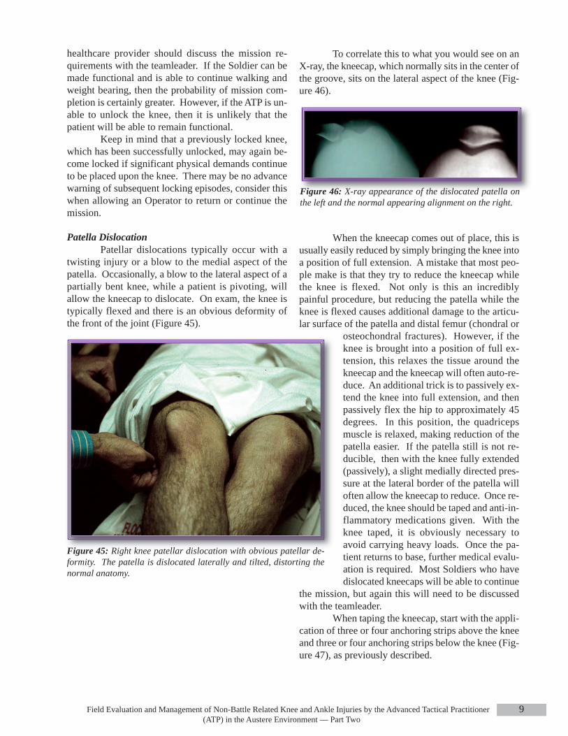
To correlate this to what you would see on anX-ray, the kneecap, which normally sits in the center ofthe groove, sits on the lateral aspect of the knee (Fig-ure 46).
When the kneecap comes out of place, this isusually easily reduced by simply bringing the knee intoa position of full extension. A mistake that most peo-ple make is that they try to reduce the kneecap whilethe knee is flexed. Not only is this an incrediblypainful procedure, but reducing the patella while theknee is flexed causes additional damage to the articu-lar surface of the patella and distal femur (chondral or
osteochondral fractures). However, if theknee is brought into a position of full ex-tension, this relaxes the tissue around thekneecap and the kneecap will often auto-re-duce. An additional trick is to passively ex-tend the knee into full extension, and thenpassively flex the hip to approximately 45degrees. In this position, the quadricepsmuscle is relaxed, making reduction of thepatella easier. If the patella still is not re-ducible, then with the knee fully extended(passively), a slight medially directed pres-sure at the lateral border of the patella willoften allow the kneecap to reduce. Once re-duced, the knee should be taped and anti-in-flammatory medications given. With theknee taped, it is obviously necessary toavoid carrying heavy loads. Once the pa-tient returns to base, further medical evalu-ation is required. Most Soldiers who havedislocated kneecaps will be able to continue
the mission, but again this will need to be discussedwith the teamleader.
When taping the kneecap, start with the appli-cation of three or four anchoring strips above the kneeand three or four anchoring strips below the knee (Fig-ure 47), as previously described.
Figure 46: X-ray appearance of the dislocated patella onthe left and the normal appearing alignment on the right.
Figure 45: Right knee patellar dislocation with obvious patellar de-formity. The patella is dislocated laterally and tilted, distorting thenormal anatomy.

Journal of Special Operations Medicine Volume 9, Edition 2 / Spring 0910
Figure 47: With the heel elevated and the knee flexed, theanchoring strops are applied as with the previously de-scribed ligament taping.
Figure 49: Second X-tape strip applied centered at the lateralpatella border.
Figure 50: Patella stabilizing tape strip initially appliedat the lateral aspect of the knee, starting posterolaterallyand advancing to the lateral border of the patella.
The criss-cross tape strips are then applied ini-tially at the lateral aspect of the knee. However, whenapplying these strips, they should be applied in a criss-cross fashion with the X-centered at the lateral borderof the patella (Figures 48 and 49), rather than at themid-portion of the joint line as done for ligament in-juries (Figures 26 and 27).
Figure 48: Crossing tape stripe is initially applied at the lateralborder of the patella, rather then at the mid joint line as shownin the insert and Figures 26 and 27.
After applying two criss-cross strips at the lat-eral border of the patella, a patella stabilizing strip isapplied (Figure 50).

Field Evaluation and Management of Non-Battle Related Knee and Ankle Injuries by the Advanced Tactical Practitioner(ATP) in the Austere Environment — Part Two
11
Figure 51: Split the tape in half lengthwise, forming a Y-shaped piece of tape with two tails.
Once the strip has been applied laterally, theremaining tail is split, forming a Y-shaped piece oftape (Figure 51).
After application of the horizontal Y-shapedpatella stabilizing strip, additional reinforcing X-tapestrips are applied to the lateral border of the patella (Fig-ures 53 and 54)
Next, the medial tape tails of the Y-shaped hor-izontal patellar stabilizing tape strip are anchored inplace by placing the X-anchoring strips medially. Aswith ligament taping, the medial X-anchoring strip arecentered at the medial joint line with a final vertical an-choring strip (Figure 55). (The medial X-tape strips andvertical strip are NOT placed adjacent to the patella.)
During the process of applying anchoring strips,remember that it is necessary to keep the posterior as-pect of the knee open so that tape blisters don’t develop.Once the criss-cross X-strips have been applied, the cir-cumferential anchoring strips are applied above andbelow the knee (Figure 56), as with the ligament taping.
After starting laterally with the base, and thenpassing half the tape at the superior border of thepatella and continuing on to the medial aspect of theknee, the second tail is applied to the inferior border ofthe patella and then onto the medial knee (Figure 52).
Figure 52: The second half of the split tape is applied justbelow the inferior border of the patella and then pulled tothe medial aspect of the knee.
Figure 53: The first additional lateral patellar anchoringstrip.
Figure 54: The second and final lateral patellar anchoringstrip.

Journal of Special Operations Medicine Volume 9, Edition 2 / Spring 0912
This taping method works to stabilize thepatella because you now have a medially directed forceapplied to the border of the patella (Figure 57) as wellas the buttressing effect of the tape strips at the lateralborder of the patella. In addition, the taping decreasesthe amount of rotation at the knee joint and the amountof flexion and extension so that the kneecap tends toremain seated in the patellar groove.
All of the treatment methods discussed in thisarticle are only meant as temporary treatments. Whenthe mission is completed, further evaluation and treat-ment should be sought for the Soldier.
In the next issue, Part 3 will discuss the eval-uation and treatment of ankle sprains.
JF Rick Hammesfahr, M.D. graduated from Colgate University in 1973 and the College ofMedicine and Dentistry of New Jersey in 1977. He was Chief Resident in Orthopaedics at EmoryUniversity from 1980-1982. In addition to receiving numerous surgical awards, he has been on thespeaking faculty of numerous medical and orthopaedic meetings serving as the co-director of sev-eral courses on knee surgery. His publications have focused on tactical medicine, arthroscopy, cal-caneal fractures, abductor paralysis, wound healing, running injuries, meniscal repair, septic knees,and sports medicine. He has written two book chapters, one book, published 22 articles, serves onthe editoral review board of multiple medical journals, is a chief editor of the “Ranger Medic Hand-book,” and has presented over 120 CME lectures and talks on orthopedics and sports injuries.
Dr Hammesfahr has served as president of the largest regional orthopaedic association, theSouthern Orthopaedic Association. Currently, he is the Director of the Center for Orthopaedics and
Sports Medicine and serves as the Chairman of the USSOCOM Curriculum and Examination Board.
This completes Part Two of this article. Part Three will appear in the Summer 2009edition and will consist of ankle injuries.
Figure 55: Medial X-tape strips applied, along with thevertical anchoring strip. This is the same pattern that wasshown in figures 26-30.
Figure 56: Proximal and distal circumferential anchoringstrips.
Figure 57:Mechanical effects of the Y-shaped patellar sta-bilizing strip.