field electrical testing - … · initiate any claim forms perform an internal ... • using megger...
TRANSCRIPT

Regional Technical Seminar
FIELD ELECTRICAL TESTING
© SPX TRANSFORMER SOLUTIONS, INC.
June 20, 2018

Field Electrical Testing Applications
2
Key Purposes of Field Electrical Testing:
Receiving inspection
Acceptance testing/commissioning of new equipment
Routine maintenance programs
Diagnostics/troubleshooting
June 20, 2018© SPX Transformer Solutions, Inc.

Receipt of Transformer
3June 20, 2018© SPX Transformer Solutions, Inc.

Receiving Inspection
4
Complete visual inspection
Review impact recorder
Impacts that warrant further
inspection
• 2 Gs – Lateral & Vertical
• 3 Gs - Longitudinal
Check tank pressure
Take dew point measurement
Perform core ground test
Inventory and inspect accessories
June 20, 2018© SPX Transformer Solutions, Inc.

Impact Recorders
Impacts that warrant further
inspection
• 2 Gs – Lateral & Vertical
• 3 Gs - Longitudinal
Mount recorder directly on
transformer
Assure there is adequate
battery life, recording paper
Redundant recorders are
recommended for critical
shipments
June 20, 2018© SPX Transformer Solutions, Inc. 5

External Inspection
June 20, 2018© SPX Transformer Solutions, Inc. 6

Receiving Inspection – As Found Conditions
7June 20, 2018© SPX Transformer Solutions, Inc.

Receiving Inspection – As Found Conditions
8June 20, 2018© SPX Transformer Solutions, Inc.

Receiving Inspection
If damage is evident from
visual inspection, impact
recorder reading, or testing:
Notify manufacturer
Notify carrier
Do not unload equipment
Initiate any claim forms
Perform an internal
inspection
June 20, 2018© SPX Transformer Solutions, Inc. 9

Receiving Inspection – Prevention Techniques
10June 20, 2018© SPX Transformer Solutions, Inc.

Insulation Moisture Content
11
Dew point measurement
• Introduce dry gas and stand idle for 12-
24 hours
• Measure dew point of gas
• Record tank pressure
• Record insulation temperature
• Utilize Pieper curve information to
calculate moisture present
• Acceptance range is less than 1.0%
June 20, 2018© SPX Transformer Solutions, Inc.

Dew point Measurement
12
Source: IEEE C57.93-2007
Dew point = -30°C
Tank Pressure = 3 PSI
Insulation Temp = 30°C
VC = 300 ( 14.7 + 3 )
14.7
VC = 361.2
VC = VP ( ATM + T P )
ATM
June 20, 2018© SPX Transformer Solutions, Inc.

Dew point Measurement
13
Moisture content is 0.9%.
Source: IEEE C57.93-2007
June 20, 2018© SPX Transformer Solutions, Inc.

Core Resistance (Megger)
14
Purpose
• Prove insulation integrity of core from ground potential and test for inadvertent core grounds.
Method
• Using megger instrument, 1000V is applied for one minute to core ground strap.
• Some transformers may have multiple core grounds and/or a separate clamp/endframe ground. Each should be tested independently
Preventative autotransformer
Series transformer
Clamp
• Some transformers may be constructed such that core ground strap is not accessible.
June 20, 2018© SPX Transformer Solutions, Inc.

Core Resistance (Megger)
15
Acceptance criteria
• Minimum standard acceptance limit is 100 megaohms when corrected to
20°C.
• Test is sensitive to temperature, moisture and contamination.
• Measured values will be different in air and oil.
June 20, 2018© SPX Transformer Solutions, Inc.

Field Acceptance Testing – Transformer Assembly
16
(Prior to assembly) Dew point (initial)
Core ground test (initial)
(After Assembly, Prior to filling) Transformer Turn Ratio (AC)
Current Transformer Testing (AC)
(Post vacuum oil processing/filling) Power Factor Testing (AC)
Excitation Testing (AC)
Frequency Response Analysis (AC)
Insulation Resistance (DC)
Winding Resistance Testing (DC)
• Core ground test (final)
• Controls and Alarm checks
Oil sample/DGA
June 20, 2018© SPX Transformer Solutions, Inc.
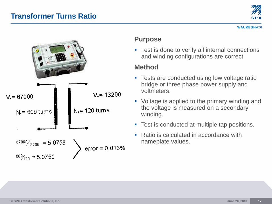
Transformer Turns Ratio
17
Purpose
Test is done to verify all internal connections and winding configurations are correct
Method
Tests are conducted using low voltage ratio bridge or three phase power supply and voltmeters.
Voltage is applied to the primary winding and the voltage is measured on a secondary winding.
Test is conducted at multiple tap positions.
Ratio is calculated in accordance with nameplate values.
June 20, 2018© SPX Transformer Solutions, Inc.

CT Ratio, Polarity & Excitation Current
18
Verify proper ratio and polarity of
current transformers
Ratio and excitation current can
be verified either by primary
current injection or secondary
voltage injection
Polarity is verified by battery
polarization or buck/boost circuits
Varied depending on relay
accuracy and burden rating of the CT. Generally ± 1% of calculated
ratio
June 20, 2018© SPX Transformer Solutions, Inc.

Field Acceptance Testing – Transformer Assembly
19
(Prior to assembly) Dew point (initial)
Core ground test (initial)
(After Assembly, Prior to filling) Transformer Turn Ratio (AC)
Current Transformer Testing (AC)
(Post vacuum oil processing/filling) Power Factor Testing (AC)
Excitation Testing (AC)
Frequency Response Analysis (AC)
Insulation Resistance (DC)
Winding Resistance Testing (DC)
Core ground test (final)
Controls and Alarm checks
Oil sample/DGA
June 20, 2018© SPX Transformer Solutions, Inc.

Oil Level Verification
20
N2 Blanketed Unit
June 20, 2018© SPX Transformer Solutions, Inc.

Oil Level Verification
21
N2 Final Level
June 20, 2018© SPX Transformer Solutions, Inc.

Oil Level Verification
22
Conservator Unit
Conservator Unit
June 20, 2018© SPX Transformer Solutions, Inc.

Oil Level Verification
23
Conservator Final Level
June 20, 2018© SPX Transformer Solutions, Inc.

Oil Level Verification
24
Determining Average Oil Temperature
Take oil temperature from liquid temperature gauge
Using infrared gun or tape on thermometer, record oil temperature at bottom of unit
Average the two readings
Determine correction factor measurement for each unit based on nameplate data as shown on previous slides
Note:
• On the N2 unit, measure from the PRD to the top of the oil as indicated
earlier
• On the Conservator unit, stick a dowel through the breather opening and
determine where it lands on top of the bag which indicates oil level. Put
a piece of tape on the dowel after calculating level.
June 20, 2018© SPX Transformer Solutions, Inc.

Power Factor Testing – Bushings
25
Purpose
Detection of moisture or foreign contamination in the insulation structure or damage or excessive contamination to external surfaces.
Method
Insulation power factor bridge is used to measure power factor and capacitance of bushings.
Test voltages are determined by bushing design and construction.
Power factor bridge shall be capable of a test voltage of 10 kV.
Readings are corrected to standard temperature.
Testing is highly susceptible to temperature, humidity and contamination.
June 20, 2018© SPX Transformer Solutions, Inc.

Power Factor Testing – Bushings
26
Detection of moisture or
foreign contamination in the
insulation structure or
damage or excessive
contamination to external
surfaces.
Sensitivity to temperature,
moisture, and
contamination
Applicable to condenser
bushings only
June 20, 2018© SPX Transformer Solutions, Inc.

Power Factor Testing – Bushings
27
C1 test checks main core
insulation
C2 test checks tap insulator
and core insulation between
capacitance tap and ground
flange.
Hot collar tests can be done
for solid bushing
June 20, 2018© SPX Transformer Solutions, Inc.

Power Factor Testing – Bushings
28
Acceptance criteria
Standard acceptance limit for bushings is 0.5% when corrected to
20°C.
Typical maintenance limits:
• Good - < 0.5%
• Deteriorated - .5% - 1.0%
• Investigate - > 1.0%
Recommended that the readings be compared to nameplate
values. Bushings should be replaced when the measured power
factor doubles the nameplate value or capacitance is in excess of
110% of the nameplate value.
June 20, 2018© SPX Transformer Solutions, Inc.

Power Factor Testing – Windings
29
Purpose
Detection of moisture or foreign contamination in the insulation structure.
Test can also detect changes in geometrical configuration of windings or damage to ground and static shields.
Method
Insulation power factor bridge is used to measure power factor and capacitance of windings.
Power factor bridge shall be capable of a test voltage of 10kV.
Tests typically completed at 10kV.
Testing his highly susceptible to temperature, humidity and contamination.
June 20, 2018© SPX Transformer Solutions, Inc.

Power Factor Testing – Windings
30
Less than 0.5% Good
> 0.5% but < 0.7% Deteriorated
> 0.5% but < 1.0% & Increasing Investigate
>1.0% Bad
Acceptance criteria
Standard acceptance limit for new transformer windings is 0.5% when
corrected to 20°C.
Natural ester fluid filled transformers will have a higher power factor
typically 2 to 4 times greater than measured in mineral oil.
For maintenance testing, the following limits are defined by Doble
Engineering
June 20, 2018© SPX Transformer Solutions, Inc.

Winding Excitation
31
Purpose
Maintenance test generally recognized to detect any changes in the magnetic circuit
Method
Voltage source is applied to winding and exciting current is measured.
Test is most often done with power factor bridge test set at 10 kV
Acceptable Criteria
This is a repeat test. All subsequent tests are compared to original baseline test for indications of variance
June 20, 2018© SPX Transformer Solutions, Inc.

Winding Excitation
June 20, 2018© SPX Transformer Solutions, Inc. 32
A B C
A B C
A B C
A Phase Excitation
C Phase Excitation
B Phase Excitation
A = C
B < A and C

Frequency Response Analysis
33
Test Methods
Impulse method (Framit)
Sweep Frequency Method (Doble)
Traces are not comparable between methods
Test for Winding Movement
Deformation
Winding Clamping
Short Circuit Damage
Comparison Test
Identical 1-Phase Units
Phases on 3-Phase Unit
Against Previous Test
June 20, 2018© SPX Transformer Solutions, Inc.

Doble SFRA Test
34June 20, 2018© SPX Transformer Solutions, Inc.

Doble SFRA Test
35
< 2kHz, core defamation,
shorted turns, residual
magnetism, open circuits
2kHz to 20kHz,
bulk winding
movement, core
clamping
20 kHz to 400kHz,
deformation within
windings
400 kHz to
2 MHz,
leads and
bushings
June 20, 2018© SPX Transformer Solutions, Inc.

Insulation Resistance (Megger)
36
Purpose
Prove insulation integrity between windings and between the winding and
ground potential.
Severe contaminants or insulation failure can be detected.
Polarization index can detect changes in insulation structure over time.
Method
Using megger instrument, 1000V to 5000V is applied for one minute
between windings and between windings and ground. If polarization index
(PI) measurement is required, test voltage must be applied for 10 minutes
in each test configuration.
Test is sensitive to moisture, temperature and contamination.
June 20, 2018© SPX Transformer Solutions, Inc.

Insulation Resistance (Megger)
37
Acceptance criteria
Minimum standard acceptance limit is 1000 Megaohms when
corrected to 20°C.
Test is sensitive to temperature, moisture and contamination.
Measured values will be different for different fluids. Natural ester
fluid filled transformers will have a reduced megger value up to 10
times less than measured in mineral oil.
June 20, 2018© SPX Transformer Solutions, Inc.

Winding Resistance
38
Purpose
Verify internal connections and detection of any open
or poor connections. This is often done as a
maintenance type test
Method
Using Wheatstone or Kelvin bridge, resistance of the
transformer winding is measured.
Test is very sensitive to temperature and must be
corrected to standard temperature for comparison.
The test is generally performed single phase of each
section of a winding.
June 20, 2018© SPX Transformer Solutions, Inc.

5
© SPX Transformer Solutions, Inc. 39June 20, 2018

6
© SPX Transformer Solutions, Inc. 40June 20, 2018

7
© SPX Transformer Solutions, Inc. 41June 20, 2018

8
© SPX Transformer Solutions, Inc. 42June 20, 2018

9
© SPX Transformer Solutions, Inc. 43June 20, 2018

Processed Oil in New Transformer
44
Test Standard Unit Voltage Value
< 69 kV 25
69 < 230 kV 30
230 < 345 kV 32
> 345 kV 35
< 69 kV 0.015
69 < 230 kV 0.015
230 < 345 kV 0.015
> 345 kV 0.015
< 69 kV 38
69 < 230 kV 38
230 < 345 kV 38
> 345 kV 38
< 69 kV 25
69 < 230 kV 10
230 < 345 kV 10
> 345 kV 10
< 69 kV 0.05
69 < 230 kV 0.05
230 < 345 kV 0.05
> 345 kV 0.05
Moisture
ContentASTM-D1533
max, PPM
@ 60°C
Avg. Oil
Temp.
Power Factor ASTM-D924max, % @
25°C
Neutralization
NumberASTM-D974
max, mg
KOH/g
Interfacial
TensionASTM-D971
min,
Dynes/cm
Dielectric
Breakdown
ASTM-D1816
w/ 1mm gap min, kV
Take baseline DGA prior to energization
Source: IEEE C57.106-2006
June 20, 2018© SPX Transformer Solutions, Inc.

Field Acceptance Testing
45
(Prior to assembly) Receiving Inspection
Dew point (initial)
Core ground test (initial)
(Prior to filling) Transformer Turn Ratio (AC)
Current Transformer Testing (AC)
(Post vacuum oil processing/filling) Power Factor Testing (AC)
Excitation Testing (AC)
Frequency Response Analysis (AC)
Insulation Resistance (DC)
Winding Resistance Testing (DC)
Core ground test (final)
Oil sample/DGA
June 20, 2018© SPX Transformer Solutions, Inc.

Energization Procedures
46
Source: C57.93-2007
Prior to energizing transformers, verify the following
• Electrical and oil tests have been complete and have met minimum standards
• Stand time after oil filling has been met
• Cooling controls have been set to automatic operation
• All temporary grounds and shorting wire have been removed
Energize the transformer with no load from either the high voltage or low voltage side. If possible, it is recommended that voltage be raised in increments.
June 20, 2018© SPX Transformer Solutions, Inc.

Energization Procedures
47
During the energization period without load,
it is recommended that close observation of
the transformer be made.
• Excessive audible noise
• Check of liquid temperatures, winding
temperatures, and ambient temperature
• Check of tank pressure
• Check of oil level indicators
• Check of gas detector relay.
Within the first month of operation, a DGA
sample should be taken for baseline analysis
June 20, 2018© SPX Transformer Solutions, Inc.

Field Testing – Routine/Preventative
48
Normal Maintenance Cycles
Unit Outages
PM programs
Validate against previous test data
Electrical testing and oil analysis
June 20, 2018© SPX Transformer Solutions, Inc.

Field Testing – Diagnostics/Troubleshooting
49
Post Incident Analysis
Abnormal test results
Known fault condition
Service bulletin
Result of oil analysis
June 20, 2018© SPX Transformer Solutions, Inc.

Field Testing – Initial Test Results – Doble Overall
50
Nameplate - Two-winding Transformer
Company Itasca Mantrap COOP Serial Number GT-01773
Location Shell Lake Sub, MN Special ID
Division
Circuit Designation
Manufacturer WAU Configuration D-Y
Year Manufactured 2013 Tank Type N2 BLANKETED
Mfr Location Goldsboro Coolant OIL
Phases 3 Class ONAN/ONAF
Oil Volume 2340 UG BIL 150 kV
Weight 54515 LB Winding Config. Delta-Wye
kV 34.5, 12.47 VA Rating 8.4, 10.5, , MVA
Note
Test Date 5/28/2014 Test Time 7:38:14 AM Weather SUNNY
Air Temperature 31 °C Tank Temperature 22 °C Rel. Humidity 0 %
Tested by
Work Order #
Last Test Date
Checked by
Test Set Type M4K Retest Date
Checked Date
Set Top S/N
Reason TROUBLE
Last Sheet #
Set Bottom S/N
Travel Time
P.O. #
Ins. Book #
Duration
Copies
Sheet #
Crew Size
Overall Tests
Meas. Test kV mA Watts %PF
corr
Corr
Fctr Cap(pF) IRauto IRman
CH + CHL 10.007 25.302 0.8530
0.99 6711.3
CH 10.005 8.174 0.3650 0.45 0.99 2168.1 G
CHL(UST) 10.008 17.118 0.5240 0.31 0.99 4540.7 G
CHL
17.128 0.488 0.28 0.99 4543.200 G
CL + CHL 10.008 47.299 1.441
0.99 12546.4
CL 10.008 30.157 0.8980 0.30 0.99 7999.3 G
CHL(UST) 10.008 17.118 0.5470 0.32 0.99 4540.7 G
CHL
17.142 0.543 0.32 0.99 4547.100 G
June 20, 2018© SPX Transformer Solutions, Inc.

Field Testing – Initial Test Results – Doble Excitation
51
Exciting Current Tests
Mfr Type Steps
Boost
%
Buck
%
Position
Found
Position
Left
Oil
Volume
De-Energized Tap
Changer
On-Load Tap Changer
H3 - H1 H1 - H2 H2 - H3
DETC LTC Test kV mA Watts X mA Watts X mA Watts X IRauto IRman
3 N/A 10.018
37.293 291.22 L 37.345 291.03 L Q
June 20, 2018© SPX Transformer Solutions, Inc.

Field Testing – Initial Test Results – Doble SFRA
52June 20, 2018© SPX Transformer Solutions, Inc.

Doble SFRA Test
53
< 2kHz, core defamation,
shorted turns, residual
magnetism, open circuits
2kHz to 20kHz,
bulk winding
movement, core
clamping
20 kHz to 400kHz,
deformation within
windings
400 kHz to
2 MHz,
leads and
bushings
June 20, 2018© SPX Transformer Solutions, Inc.

Field Testing – As Found Conditions
54June 20, 2018© SPX Transformer Solutions, Inc.

Field Testing – As Found Conditions
55June 20, 2018© SPX Transformer Solutions, Inc.

Field Testing – As Found Conditions
56June 20, 2018© SPX Transformer Solutions, Inc.

Field Testing – As Found Conditions
57June 20, 2018© SPX Transformer Solutions, Inc.

Field Testing – As Found Conditions
58June 20, 2018© SPX Transformer Solutions, Inc.

Test References
59
IEEE Guide for Installation of Liquid Immersed Power
Transformers (C57.93-2007)
IEEE Guide for Maintenance and Acceptance of Insulating Oil
in Equipment (C57.106-2006)
IEEE Guide for Interpretation of Gasses Generated in
Electrical Equipment (C57.104-2008)
NETA Acceptance Testing Specification 2010
IEEE Guide for Failure Investigation, Analysis, and
Documentation of Power Transformers and Shunt Reactors
(C57.125-1991 Appendix A)
IEEE C57.152 Field Diagnostics Guide (New)
June 20, 2018© SPX Transformer Solutions, Inc.

Common Issues Found With Test
June 20, 2018 60
1. Bushing Power factor
1. Power Factor in Crate
2. Hard to PF Bushings on Straps if Large Bushing
1. Supposed to have standing up for 24 hours
3. Resistance Readings not making since
1. Make sure that you have give enough time to let readings settle
2. If taking to long then check into different setups
4. SFRA or Excitation not correct
1. Check for magnetized core
5. Megger should show inductive kick
1. How often do you 20,000 Meg Ohms +
2. If no inductive kick then core ground might not be connected to the core ground.
© SPX Transformer Solutions, Inc.

Questions?Thank you!