fibre reinforcement and the rheology of...
TRANSCRIPT

© Woodhead Publishing Limited, 2012
229
9 Fibre reinforcement and the rheology
of concrete
S . GRÜNEWALD, Delft University of Technology, The Netherlands
Abstract: The addition of fi bres can improve the performance of cementitious materials in the hardened state. With an optimized mixture composition and controlled rheology and quality, fi bres can become more effective. Signifi cant progress has been made during the past years on the fi eld of fl ow simulations and the rheology of fi bre suspensions. The main diffi culties are related to the non-Newtonian behaviour of fi bre suspensions (i.e. shear-thinning due to fi bre orientation and local fl ow-induced structures) and diffi culties in predicting and measuring the different contributions of, for example, hydrodynamic effects and mechanical interaction. Fibre rheology and fl ow simulation are excellent tools to optimize fi bre suspensions and form the basis for predictions of structural performance.
Key words: fi bres, cementitious materials, rheology, fl ow simulation, fi bre orientation.
9.1 Introduction
This chapter addresses aspects related to fi bres and rheology. Rheology and the simulation of fl ow are important to understand and to optimize the structural behaviour of fi bre-reinforced cementitious materials. Rheologically speaking, fi bre suspensions are non-Newtonian fl uids and can display normal stress differences. Fibre simulation is a branch of mechanics that deals with modelling the dynamics and rheology of particles of large aspect ratio, or fi bres, with the goal of predicting the properties of fi bre suspensions and networks.
Many studies have demonstrated the benefi ts of adding fi bres to cementitious materials. Fibres can improve the ductility, increase tensile as well as shear strength, are able to enhance fatigue strength and impact resistance, can counteract shrinkage cracking and prevent spalling in case of fi re loading. Fibres have been applied in cementitious materials as reinforcement to replace rebars, to improve the structural performance and for crack width control. Innovative, slender structures can be designed with, for example, engineered cementitious composites (Li, 2002) and ultra high performance concrete (Resplendino, 2011), taking into account the specifi c tensile behaviour.
The effect of fi bres on workability has been recognized and studied for many years due to the need to produce structures with a ‘workable’ concrete. Recent developments in material technology show that fi bre dosages can be signifi cantly

230 Understanding the rheology of concrete
© Woodhead Publishing Limited, 2012
increased with adjusted mixture compositions and production techniques, i.e. concrete with self-compacting ability. In contrast to traditionally vibrated concrete, highly fl owable/workable concrete requires little or no vibration energy to be placed. This implies that not only the mixture composition but also the production process have to be ‘tailored’ to the devised application, fi nally aiming at an optimized structural performance. The performance of fl owable cementitious materials depends on the material behaviour, the production method and infl uences related to the structure ( Fig. 9.1 ).
Fibres can be more effi cient in the hardened state with an optimized mixture composition and a controlled rheological behaviour. This is achieved by minimizing mechanical interaction and interlocking of fi bres during the fl ow and the production stage. Due to the fl ow or strain of the concrete, fi bres are able to orient; this makes the prediction of the structural behaviour of fi bre-reinforced concrete more complex, but it also offers the potential for an improved structural performance. Synergetic effects were observed with fl owable concrete on the micro-level (matrix-fi bre interaction: Markovic et al. , 2002), the macro-level (preferred fi bre orientation: Ferrara et al. , 2010 and Laranjeira et al. , 2011) and the structural level (i.e. due a lower variation of fi bre orientation at increasing alignment of the fi bres: Laranjeira et al. , 2010). With fl owable concrete, special attention is required to obtain the desired performance.
Rheological characteristics are essential input parameters for fl ow simulations of both vibrated and fl owable fi bre concretes. The position and the orientation of fi bres in a structure can differ from the assumed isotropic orientation and distribution due to dynamic/static segregation or fl oating of fi bres, blocking during the fl ow and/or the orientation of fi bres caused by the fl ow and induced by walls. As well as for cementitious materials, the rheology of fi bre suspensions is
9.1 Structural performance as a result of three components: material behaviour, production effects and structural boundaries (Grünewald et al. , 2010).
Fibre reinforcement and the rheology of concrete 231
© Woodhead Publishing Limited, 2012
relevant to other industrial suspensions like polymers, which contain rod-like particles (i.e. Kevlar, nylon, glass or wollastonite).
9.2 Fibres in cementitious materials
9.2.1 Introduction to fi bres used in cementitious materials
Fibres are long, slender particles with a high aspect ratio r ( r = L f / d f : fi bre length divided by the fi bre diameter) that can cause diffi culties during production and processing. In order to optimize cementitious materials with fi bres, aspects such as workability and rheology have to be addressed. Due to the elongated shape of the fi bres, their effect depends on the position and the orientation within a structure and relative to principal stresses. Below fi bres in cementitious materials are discussed, particularly fi bre types and their effect on mixture characteristics. The physical characterisation of fi bres and their infl uence on packing density is also addressed.
9.2.2 Fibre types
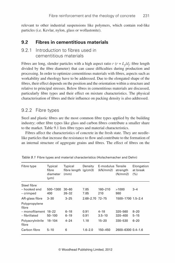
Steel and plastic fi bres are the most common fi bre types applied by the building industry; other fi bre types like glass and carbon fi bres contribute a smaller share to the market. Table 9.1 lists fi bre types and material characteristics.
Fibres affect the characteristics of concrete in the fresh state. They are needle-like particles that increase the resistance to fl ow and contribute to the formation of an internal structure of aggregate grains and fi bres. The effect of fi bres on the
Table 9.1 Fibre types and material characteristics (Holschemacher and Dehn)
Fibre type Typical fi bre diameter (µm)
Typical fi bre length (mm)
Density (g/cm3)
E-modulus (kN/mm2)
Tensile strength (N/mm2)
Elongation at break (%)
Steel fi bre– hooked end 500–1300 30–60 7.85 160–210 >1000 3–4– crimped 400 26–32 7.85 210 980
AR-glass fi bre 3–30 3–25 2.68–2.70 72–75 1500–1700 1.5–2.4
Polypropylene fi bre– monofi lament 18–22 6–18 0.91 4–18 320–560 8–20– fi brillated 50–100 6–19 0.91 3.5–10 320–400 5–15
Polyacrylnitrile fi bre
18–104 4–24 1.18 15–20 330–530 6–20
Carbon fi bre 5–10 6 1.6–2.0 150–450 2600–6300 0.4–1.6
232 Understanding the rheology of concrete
© Woodhead Publishing Limited, 2012
workability is mainly due to four reasons: First, the shape of the fi bres is more elongated compared to the aggregates; the surface area at the same volume is larger. Second, stiff fi bres change the structure of the granular skeleton, whereas fl exible fi bres fi ll the space between them. Stiff fi bres push apart particles that are relatively large compared to the fi bre length, which increases the porosity of the granular skeleton. Third, the surface characteristics of fi bres differ from that of cement and aggregates, i.e. plastic fi bres might be hydrophilic or hydrophobic. Finally, fi bres can be deformed (i.e. have hooked ends, be crimped or wave-shaped) to improve the anchorage between them and the surrounding matrix.
With long and stiff steel fi bres (aspect ratio 45–80, fi bre length 30–60 mm), the mechanical interaction of fi bres and aggregates dominates the fl ow behaviour; the surface area of these fi bre types is comparable to coarser sand fractions. In contrast, thin plastic fi bres and fi bres at a very high aspect ratio can have a much higher surface area. Plastic fi bres mainly affect the rheological behaviour of the paste. Due to their fl exibility, the mechanical interaction with aggregates is much less pronounced but they can still form a network with aggregates and other fi bres. The fl exibility of fi bres has two effects: ‘the deformation of fi bres’ and ‘the formation of entangled structures’ (Yamanoi et al. , 2010). The shear viscosity increased at increasing fl exibility (Keshtar et al. , 2009). The presence of steel fi bres affects the yield stress of concrete but alters the paste characteristics to a minor degree. A structure produced with a fi bre-reinforced concrete still can have a smooth and faultless surface, even at a relatively small slump fl ow (550–600 mm) or medium slump (100–150 mm).
The stiffness of fi bres can be calculated using Eq. 9.1 (Martinie et al. , 2010). The lower the ratio f / L f ( f: fl exibility, L f : fi bre length) the stiffer the fi bre behaves. The ratio f / L f was 0.03% for a stiff steel fi bre ( r = 50, E = 190 000 MPa, self-compacting concrete: τ 0 = 50 Pa), whereas it is 66% for a fl exible carbon fi bre ( r = 500, E = 210 000 MPa, traditional vibrated concrete: τ 0 = 1000 Pa).
[9.1]
where f = fi bre fl exibility (mm 4 ), E = E-modulus (MPa) and τ 0 = yield value (Pa). In order to optimize the performance of an individual fi bre, fi bres need to be
homogenously distributed in a matrix and clustering of fi bres has to be counteracted. The size of the fi bres relative to the aggregates determines their distribution (Johnston, 1996). To be effective in the hardened state it is recommended to choose fi bres not shorter than the maximum aggregate size (Johnston, 1996; Vandewalle, 1993). Usually, the fi bre length is 2–4 times that of the maximum aggregate size.
9.2.3 Packing density
According to Yu and Zou (1998), the initial packing density of irregular particles depends on the shape and size of the particles and the applied compaction energy.

Fibre reinforcement and the rheology of concrete 233
© Woodhead Publishing Limited, 2012
The packing density of fi bres (when randomly placed) is much lower compared to a single grain fraction. The packing density of fi bres is also affected by the stiffness of the fi bres. Flexible fi bres (i.e. plastic fi bres) can be compressed and, at commonly applied fi bres dosages, have little effect on the packing density of the aggregates. Placing fi bres in an orderly (aligned) manner, which cannot be realised by mixing cementitious materials, can result in a much higher packing density. Zou and Yu (1996) proposed a formula (Eq. 9.2) to approximate the experimental (dense and randomly placed) packing density of cylinders. The ‘sphericity’ (Eq. 9.3) is the ratio of the surface area of the sphere, having the same volume as the particle and its actual surface area; the ‘volume diameter’ is the diameter of a sphere having the same volume as the particle (Yu et al. , 1993). The comparison of predicted values obtained with Eq. 9.2 and experimental results on the packing density carried out with a variety of (stiff) steel fi bres showed a good agreement (Grünewald, 2004). Crimped and hooked ends fi bres were applied in this study.
[9.2]
where ε 0d,cyl = dense (experimental) packing density of fi bres and ψ = sphericity, with Yu et al. (1993):
[9.3]
where d f = fi bre diameter (mm) and L f = fi bre length (mm). Philipse (1996) showed that, for high aspect ratio bodies, the packing density
can be calculated with: φ c = α c / r (loose packing) and φ m = α m / r (dense packing). In the aspect ratio range of 50–100, the parameters α c and α m were found to be 3.2 and 4.0, respectively (Martinie et al. , 2010). The relative size of fi bres and aggregates also affects the packing density. Figure 9.2 shows results of packing experiments (average of three measurements) with (1.5 vol.-%) and without steel fi bres for different sand contents (sand: 0–4 mm, coarse aggregates 4–16 mm). The actual fi bre content in concrete at 1.5 vol.-% of the granular skeleton is lower since concrete also contains paste: assuming a paste content of 38 vol.-% in self-compacting concrete, the content of steel fi bres equals 0.93 vol.-%. The higher the aspect ratio and the lower the content of sand, the more pronounced is the effect on packing density. At a sand content of 75 vol.-%, about the same packing density was found for different types of steel fi bres. The maximum packing density decreases after the addition of steel fi bres and shifts towards higher sand contents. To compensate for the effect of the fi bres, the mixture composition has to be adjusted by increasing the content of grains that are relatively small compared to the fi bre length. It was not possible to test 3.0 vol.-% of fi bres having an aspect ratio of 60 or higher since fi bre clustering counteracted a homogenous distribution of the fi bres.

234 Understanding the rheology of concrete
© Woodhead Publishing Limited, 2012
Stiff fi bres can be implemented in numerical calculations to determine the packing density (i.e. with the ‘compressible packing model (CPM)’; de Larrard, 1999 (cf. Chapter 7 )) by applying one of the following approaches:
Concept of the ‘perturbed zone’
The perturbed zone is the disturbed area (with a locally decreased packing density) close to a wall, in this case the fi bre (de Larrard, 1999). The mean packing density can be calculated using Eq. 9.4. The perturbed volume v P can be determined according to Table 9.2 , depending on the size and shape of the fi bres.
[9.4]
where ᾱ = mean packing density (affected by the container size) (–), φ f = percentage of fi bres of the granular skeleton (–), N sf = number of steel fi bres (–), v p = perturbed volume in a container (vol.–%) and α = unperturbed packing density (–).
Concept of the ‘equivalent packing diameter’
Yu et al. (1993) proposed the concept of the ‘equivalent packing diameter’ to include non-spherical particles in numerical simulations. In their approach, the shape and the dimension of a non-spherical particle were related to the diameter of a fi ctitious sphere having an equivalent diameter that did not result in a change of the packing density when combined with a spherical grain of the same diameter. Equation 9.5 was proposed to calculate the equivalent packing diameter for a particle with a cylindrical shape. The volume diameter d v can be calculated according to Eq. 9.6:
9.2 Effect of the sand content and the type of the steel fi bres (at 1.5 vol.-%) on packing density (Grünewald, 2004).

Fibre reinforcement and the rheology of concrete 235
© Woodhead Publishing Limited, 2012
[9.5]
where d p = equivalent packing diameter (mm) and ψ = sphericity (–).
[9.6]
where d f = fi bre diameter (mm) and L f = fi bre length (mm).
9.2.4 Mix design principles for fi bre-reinforced concrete
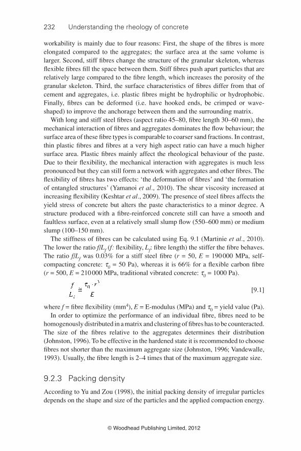
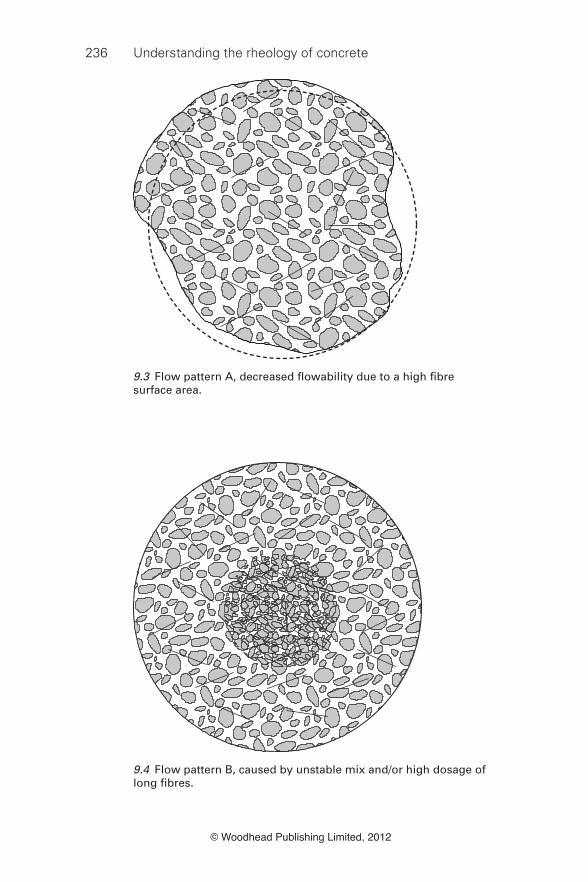
The size, shape and content of the coarse aggregates as well as the geometry and volume fraction of steel fi bres affect the workability of concrete (Swamy, 1975). The maximum fi bre content is the critical fi bre dosage at which the compactability/workability drastically decreases and/or the content of the fi bres beyond which fi bre balling takes place. Figures 9.3 to 9.5 show fl ow patterns (slump fl ow test) that indicate that the maximum fi bre dosage is exceeded (Grünewald, 2004). The type of fl ow pattern depends on the fi bre type ( Fig. 9.3 : fi bres with a high surface area, Fig. 9.4 : long stiff fi bres and Fig. 9.5 : intermediate aspect ratio, stiff fi bres).
The relative fi bre to coarse aggregate volume and the ‘balling up’ phenomenon govern the maximum possible content of steel fi bres (Swamy and Mangat, 1974). Depending on the mixture composition, the maximum concentration of steel fi bres was reached at a fi bre factor ( V f · L f / d f ) between 0.3 and 1.9 (Grünewald, 2004). Mix design methods for fi bre-reinforced concrete have been proposed by Rossi (1990), Grünewald (2004), Ferrara et al. (2007) and Martinie and Roussel (2010).
9.3 Fibre rheology
9.3.1 Introduction to fi bre rheology
Cementitious materials with fi bres are often highly concentrated suspensions. The interaction of fi bres and fi bres with grains (fi llers, cement and aggregates) determines the kind of network they form. In fl owing suspensions, three kinds of forces coexist to various degrees (Barnes et al. , 1989):
Table 9.2 Calculation of the perturbed volume
Cross-section fi bre Perturbed volume
R L A B
Round with diameter df π·R2·L 0.5·(df + kf ·d ) L f ·d /2 – –Rectangular with sides af + bf A·B·L – L f·d /2 af + kf ·d bf +kf ·d
Note: k f = 0.065, d = grain diameter
236 Understanding the rheology of concrete
© Woodhead Publishing Limited, 2012
9.3 Flow pattern A, decreased fl owability due to a high fi bre surface area.
9.4 Flow pattern B, caused by unstable mix and/or high dosage of long fi bres.

Fibre reinforcement and the rheology of concrete 237
© Woodhead Publishing Limited, 2012
• forces of colloidal origins (interactions between particles result in repulsion or attraction);
• Brownian randomising force, which ensures that particles (mainly smaller than 1 µm) are in constant movement;
• viscous forces acting on particles, which are proportional to the local velocity difference between the particle and the surrounding fl uid.
Fibre–fi bre interactions include hydrodynamic effects as well as mechanical contacts. The phase volume of solids ( Φ ) suspended in a liquid determines the extent to which hydrodynamic forces act on the surface of the particles. Resistance to fl ow arises because particles have to move out of each other’s way. The slender shape of fi bres causes them to rotate and to orientate during the fl ow. This motion is affected and/or counteracted by neighbouring particles/fi bres. Constitutive equations and fi bre orientation evolution equations can be applied to model the behaviour of fi bre suspensions. Direct simulations can be executed with the input of acting forces to predict fi bre motion and stresses in a suspension.
9.3.2 Infl uence of fi bres on viscosity and yield value
Concerning their rheological effect, fi bre suspensions can be divided in four regimes: dilute, semi-dilute, semi-concentrated and concentrated Table 9.3 (Fan et al. , 1998). Fibres are able to rotate freely in the diluted regime; at higher concentrations
9.5 Flow pattern C, Flow patterns A and B combined, obstructed fl ow and fi bre clustering.

238 Understanding the rheology of concrete
© Woodhead Publishing Limited, 2012
(semi-dilute and semi-concentrated regimes), the free rotation of the fi bres is counteracted to some degree by mechanical contacts.
Fibres interact only via hydrodynamic effects in the semi-dilute state, whereas direct contact governs the semi-concentrated state. The fi bre–fl uid interaction governs the dilute and semi-dilute regimes, whereas with concentrated suspensions (and long fi bres), the fi bre–fi bre interaction is dominating (Thomasset et al. , 1997). Increasing the fi bre dosage also increases possible fi bre interactions. In the concentrated state, the maximum packing density is reached. Martinie et al. (2010) defi ned three regions with different degrees of fi bre interaction ( Table 9.4 ). Einstein (1906, 1911) predicted the viscosity of dilute dispersed suspensions (phase volume ≤ 10%) with Eq. 9.7. Batchelor (1977) extended Eq. 9.7 and included the effect of particles of other sizes by adding higher order terms.
[9.7]
where φ = volume fraction of solids (vol.-%), η = viscosity of suspension (Pa·s) and η s = viscosity of suspending fl uid (Pa·s).
The ratio between the phase volume and the packing density has to be considered in order to predict the fl ow behaviour of concentrated suspensions like cementitious materials (Sedran, 1999). When the ratio of phase volume to packing density equals one, the fl ow is counteracted by a solid contact network. The packing concept was applied for the development of ultra high performance concrete: by increasing the packing density a high fl owability was maintained and the strength increased. Krieger and Dougherty (1959) applied the packing of particles to predict the viscosity of concentrated suspensions (Eq. 9.8). The intrinsic viscosity ( η ) depends on the rate of strain, the Péclet number and on the geometry of the suspended particles (Petrie, 1999).
Table 9.3 Rigid fi bre suspension classifi cation
Φ · r2 Φ · r Φ Regime
Φ · r2 << 1 Φ · r << 1 Φ << 1 DiluteΦ · r2 >> 1 Φ · r << 1 Φ << 1 Semi-diluteΦ · r2 >> 1 Φ · r >> 1 i << 1 Semi-concentratedΦ · r2 >> 1 Φ · r >> 1 Φ ≅ 1 Concentrated
Source: Martinie et al. (2009)
Table 9.4 Fibre interaction dependent on the packing density
Regime Fibre volume Infl uence
1 Φfc ≤ 3.2/i Low infl uence2 Φfc > 3.2/r ; Φfm ≤ 4.0/r Dominated by contact network3 Φfm > 4.0/r No fl ow, ball formation and air entrained
Note: Φ fc : random loose packing; Φ fm : random dense packing

Fibre reinforcement and the rheology of concrete 239
© Woodhead Publishing Limited, 2012
[9.8]
where φ m = solid volume (dense packing) (vol.-%), η = intrinsic viscosity (–) and η s = viscosity of suspending fl uid (Pa·s).
The packing density of aggregates (without fi bres) can be increased by widening the particle-size distribution (cf. Chapter 7 ). The interaction between stiff fi bres and aggregates increases with larger aggregates and, as a consequence, the packing density might decrease when adding larger aggregates with the result that this mixture adjustment not necessarily results in a decrease of the viscosity. Non-spherical particles lead to poorer space-fi lling (Barnes et al. , 1989). Clarke (1967) determined the effect of the shape of particles on viscosity ( Fig. 9.6 ). Dependent on the deviation of fi bres from the spherical shape (as a measure, Eq. 9.3 defi nes ‘sphericity’), the viscosity increased. A relative increase of the viscosity at increasing aspect ratio was found by Giesekus (1983). Particle fl occulation and local concentrations of particles (like fi bre balling) further decrease the packing density and increase the viscosity.
In particular, stiff fi bres decrease the packing density and, consequently, increase the viscosity at the same phase volume compared to grains. Two equations have been proposed to predict the critical volume fraction of fi bres ( φ cf ) in a suspension: Eq. 9.9 (Kitano et al. , 1981) was obtained for polymer melts with average aspect ratios of 6–27, whereas Eq. 9.10 (Pabst et al. , 2006) was proposed
9.6 Dependence of the viscosity of differently shaped particles in water on the concentration at a shear rate of 300 1/s; (■) spheres, (□) grains, (●) plates, (○) rods (Clarke, 1967).
240 Understanding the rheology of concrete
© Woodhead Publishing Limited, 2012
for wollastonite suspensions ( r ≤ 22). Possible reasons for differences in the critical volume fraction are the agglomeration and the presence of high aspect ratio wollastonite particles.
[9.9]
[9.10]
9.3.3 Shear-thinning/shear-thickening
When properly placed in one direction, the packing density of fi bres can be higher than 0.80 (Martinie et al. , 2010). This orderly state cannot be obtained when randomly adding and mixing fi bres. However, the packing density of fi bres in concrete can be increased after mixing by orienting fi bres (i.e. during the fl ow along walls, testing a suspension with a viscometer, or casting by pumping). The fl ow brings about a more favourable arrangement (Barnes et al. , 1989) and rheological characteristics can become ‘anisotropic’ with a possible favourable rearrangement of fi bres in one or two directions. The fl oc formation of fl exible fi bres in a suspension is the result of mechanical contact and coherence due to interlocking by the elastic bending of the fi bres with shear-thinning being the consequence (Sepehr et al. , 2004).
All concentrated suspensions will show shear-thickening at the correct conditions; the circumstances and severity depend on the phase volume, the particle size distribution and the continuous phase viscosity (Barnes et al. , 1989). Above a critical shear stress that decreases at increasing phase volume, shear thickening takes place.
9.3.4 Modelling fi bre rheology
Fibre suspensions have many degrees of freedom due to the large number and complex geometry of the components, the complexity of the fl ow and non-linear material behaviour. Most modelling of fi bre suspensions has been executed for dilute suspensions and at a defi ned aspect ratio. The prediction of the fl ow behaviour of concentrated fi bre suspensions is more complex and requires the use of numerical tools in order to take into account the interaction of many particles. Advani and Ait-Kadi (1997) discussed the diffi culty in obtaining and comparing experimental results with simulations. The coupling of rheology and fi bre orientation dynamics complicates predictions since it also affects the fi bre motion. Petrie (1999) reviewed the literature on the rheology of fi bre suspensions and paid special attention to modelling. According to Petrie, three steps are required to construct a rheological model:
• Model the motion of an individual fi bre in a homogenous, possibly time-dependent, fl ow fi eld.

Fibre reinforcement and the rheology of concrete 241
© Woodhead Publishing Limited, 2012
• Model the evolution of the distribution of the orientation of many such fi bres. • Calculate the contribution to the bulk stress due to the fi bres in the terms of
bulk fl ow.
It has been experimentally confi rmed that a rod-like particle rotates in a tumbling motion (Petrie, 1999). The orbit which a fi bre describes is independent of time and depends on the individual orientation of the particle and a steady state cannot be obtained without particle interaction. Particle–particle interactions, the polydispersity and non-uniformity of particles mainly affect the rotation of the fi bres (Zirnsak et al. , 1994). Jeffrey’s equation (Jeffrey, 1922; Eq. 9.11) provides a basic mathematical solution to how a single ellipsoid fl ows and rotates in a viscous Newtonian fl uid and has been applied to describe the fl ow of fi bre suspensions. The motion is referred to as Jeffrey’s Orbit. The following differential equation describes the evolution of orientation for an ellipsoid, represented by its unit vector p. W is the vorticity tensor and D the rate of strain tensor for the fl ow unperturbed by the fi bre. λ is a parameter dependent only on the slenderness r of the fi bres. In the absence of interactions and in concentrated suspensions, fi bres spend a large portion of time nearly aligned in the fl ow direction.
[9.11]
The position and the velocity of particles was re-evaluated at different time steps with non-equilibrium molecular dynamics (NEMD) after providing an initial set of both parameters (Barnes et al. , 1989). The output of the calculation is a stress (pressure) tensor with which the viscosity and normal stress differences can be calculated. Simulations showed the formation of two-dimensional layers (a fl ow-induced structure) for spherical particles. The tendency of a material to form two-dimensional structures causes shear-thinning.
Simulations with the particle simulation method (PSM) were executed to predict the evolution of fi bre orientation and the interaction of fi bre structures and rheological characteristics for rigid glass fi bres (Yamanoi and Maia, 2010) and fl exible nylon fi bres (Yamanoi et al. , 2010). Each fi bre was modelled as an array of beads. The translational and the rotational movements of each bead of a fi bre were calculated. Hydrodynamic interactions were considered for intra-fi bre and lubrication forces to determine inter-fi bre interaction; repulsive forces were also taken into account by the PSM method. The calculation according to the stress expression method requires solving constitutive equations. The stress tensor τ , the stresslet S i and the orientation tensor ‘ a ’ are the basic input parameters for the software. The considered concentration region was 1 ≤ n · d f · L f ≤ 5 (Yamanoi et al. , 2010); n being the number of fi bres per unit volume, d f the diameter of the fi bres and L f the length of the fi bres. Rheological properties were determined by parallel plate rheometry. Afterwards, results of simulations were compared with experimental results. The agreement for rigid fi bres was good up to the onset of the concentrated regime ( n · d f · L f ≤ 3); the shear viscosity and the elasticity were
242 Understanding the rheology of concrete
© Woodhead Publishing Limited, 2012
overestimated in the concentrated regime. The simulations were less accurate with fl exible fi bres; the discrepancy probably being caused by the fact that hydrodynamic interactions become more important for fl exible fi bre suspensions. Yamamoto and Matsuoka (1993, 1995a, 1995b, 1996) executed direct simulations with a similar approach and modelled fi bres as an array of spheres, which allowed them to predict the fl ow of rigid as well as fl exible fi bres.
To simulate the fl ow of cementitious fi bre suspensions, a variety of particles (especially aggregates) concerning size and shape has to be considered. Ausias et al. (2006) simulated the fl ow of fi bre suspensions taking into account a distribution of fi bre aspect ratios (average r : 19.2 and σ : 3.05) and studied the transient (fi rst stage of fl ow) and steady state (almost all fi bres are oriented) behaviour under simple shear. Hydrodynamic interaction via lubrication forces, contact forces and hydrodynamic forces was taken into account in order to predict the motion and the orientation of the fi bres. The effective stresses of fi bre suspensions were calculated and showed qualitative agreement with experimental results.
9.3.5 Fibre orientation
By simulating the fl ow and the orientation evolution of fi bres, their position and alignment relative to the direction of stress in a structure can be predicted. This information is essential for the design of structures and the micro- and macro-mechanical analysis of the performance of fi bre-reinforced concrete. The assumption of a homogenous fi bre distribution has to be verifi ed and can be achieved by adequate mix design and an adjusted production technique. Dependent on the rheological characteristics and the mixture composition, a concrete with fi bres can be either ‘rolling’ or ‘fl ow as a plug’. The former is the case for a low yield value self-compacting concrete at a low fi bre loading, whereas the latter is obtained when the concrete is less fl owable and/or the fi bres form a network, which infl uences the fl owability and the yield value. Consequently, the kind of fl ow pattern determines whether fi bres orient or not. In shear fl ows, fi bres orient in the direction of fl ow, whereas in extensional fl ow they tend to a stable orientation perpendicular or parallel to the fl ow according to the sign of the elongational rate (Vincent et al. 1997).
The most common way to calculate the orientation distribution involves a structure tensor (defi ned as an average of the second moment of the fi bre orientation vector) and to obtain a complete set of equations – a closure approximation (Petrie, 1999). Several parameters infl uence the orientation of fi bres (Martinie and Roussel, 2010): the slenderness, the interaction with other particles, the phase concentration and the location of a fi bre (proximity to a wall, location within or outside the plug-fl ow area). The closer to a wall a fi bre starts, the quicker it aligns in the direction of the fl ow. Martinie and Roussel applied Eq. 9.12 to calculate the average orientation factor deduced from calculations with Eq. 9.11. For a two-dimensional fl ow, the orientation factor relates the behaviour
Fibre reinforcement and the rheology of concrete 243
© Woodhead Publishing Limited, 2012
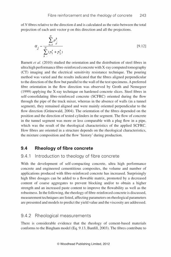
of N fi bres relative to the direction d and is calculated as the ratio between the total projection of each unit vector p on this direction and all the projections.
[9.12]
Barnett et al. (2010) studied the orientation and the distribution of steel fi bres in ultra high performance fi bre-reinforced concrete with X-ray computed tomography (CT) imaging and the electrical sensitivity resistance technique. The pouring method was varied and the results indicated that the fi bres aligned perpendicular to the direction of the fl ow but parallel to the wall of the test specimens. A preferred fi bre orientation in the fl ow direction was observed by Groth and Nemegeer (1999) applying the X-ray technique on hardened concrete slices. Steel fi bres in self-consolidating fi bre-reinforced concrete (SCFRC) oriented during the fl ow through the pipe of the truck mixer, whereas in the absence of walls (in a tunnel segment), they remained aligned and were mainly oriented perpendicular to the fl ow direction (Grünewald, 2004). The orientation of the fi bres depended on the position and the direction of tested cylinders in the segment. The fl ow of concrete in the tunnel segment was more or less comparable with a plug fl ow in a pipe, which was the result of the rheological characteristics of the applied SCFRC. How fi bres are oriented in a structure depends on the rheological characteristics, the mixture composition and the fl ow ‘history’ during production.
9.4 Rheology of fi bre concrete
9.4.1 Introduction to theology of fi bre concrete
With the development of self-compacting concrete, ultra high performance concrete and engineered cementitious composites, the volume and number of applications produced with fi bre-reinforced concrete has increased. Surprisingly high fi bre dosages can be added to a fl owable matrix, promoted by a decreased content of coarse aggregates to prevent blocking and/or to obtain a higher strength and an increased paste content to improve the fl owability as well as the robustness. In the following, the rheology of fi bre-reinforced concrete is discussed, measurement techniques are listed, affecting parameters on rheological parameters are presented and models to predict the yield value and the viscosity are addressed.
9.4.2 Rheological measurements
There is considerable evidence that the rheology of cement-based materials conforms to the Bingham model (Eq. 9.13, Banfi ll, 2003). The fi bres contribute to

244 Understanding the rheology of concrete
© Woodhead Publishing Limited, 2012
the formation of an internal network in concrete and increase the yield stress. A Bingham material behaves like a solid below the yield value; when the stress exceeds the yield value it starts to fl ow. During the fl ow, mechanical contacts between fi bres and aggregates increase the resistance to fl ow and the plastic viscosity.
[9.13]
where γ͘ = shear rate (1/s), τ = shear stress (Pa), τ 0 = yield value (Pa) and µ = plastic viscosity Bingham model (Pa·s).
Standard workability tests have been applied for traditional vibrated fi bre-reinforced concrete, although only the V-B test was at all successful (Tattersall and Banfi ll, 1983). Due to the internal structure, fi bre-reinforced concrete often appears stiffer; with some vibration this drawback can be overcome. Test methods that require little or no vibration are also applicable for fl owable concretes with fi bres. Table 9.5 lists rheological instruments reported in the literature for the study of the rheological effect of fi bres on cementitious materials. Designed for conventional cementitious materials, the ratio of the gap width to particle size of a viscometer decreases since a fi bre is usually the largest component of a mixture. Fibres can align due to the effect of walls and during the movement of a shearing body in a rheometer and, as a consequence, the rheological characteristics of fi bre-reinforced concrete are shear-rate and shear strain-dependent. Fibre orientation is counteracted with the MKIII two-point workability test due to the planetary motion of the impeller (Tattersall and Banfi ll, 1983). Martinie et al. (2010) measured the (static) yield value of fi bre-reinforced cementitious materials, assuming that orientation had not yet taken place at this fl ow stage.
Table 9.5 Rheological measurements with fi bre-reinforced cementitious materials
Type of viscometer Name of test instrument Reference
Impeller with planetary motion
MK III two point workability tester
Tattersall and Banfi ll, 1983
MK III two point workability tester
Tattersall, 1991
UBC rheometer Beaupré, 1994IBB rheometer Khayat and Roussel, 1999
Coaxial cylinder viscometer BML viscometer Grünewald, 2004Viskomat NT Banfi ll et al., 2006BML viscometer Krage and Wallevik, 2007BML viscometer Kristjánsson et al., 2009
Vane Haake viscotester VT550 Martinie et al., 2010
Parallel plate/vane Own development Laskar and Talukdar, 2008 Own development Kuder et al., 2007

Fibre reinforcement and the rheology of concrete 245
© Woodhead Publishing Limited, 2012
9.4.3 Effect of fi bres on rheological characteristics
Few studies are reported in literature on the effect of fi bres on rheological characteristics of cementitious materials. Tattersall (1991) studied the effect of steel fi bres on the rheological characteristics of concrete and found that the addition of the fi bres increased both the yield value as well as the plastic viscosity compared to a reference concrete without fi bres. Tattersall and Banfi ll (1983) found that the parameters g and h (correlated with yield value and viscosity, respectively) increased with increasing fi bre content, whereas increasing the fi bre length mainly increased g but had little effect on h . Laskar and Talukdar (2008) studied the infl uence of the fi bre volume (same fi bre type), the aspect ratio (same diameter and fi bre dosage) and the fi bre diameter (same fi bre dosage and aspect ratio) on rheological characteristics. In most cases, the yield value and the plastic viscosity increased at increasing fi bre volume and with a higher aspect ratio. However, at the lowest fi bre dosage (0.25 vol.-%), the yield stress and the plastic viscosity were lower in one case, respectively, indicating that the fi bres are not yet dominating the rheological behaviour. An effect of the fi bre diameter was observed only on the plastic viscosity; the dosage steel fi bres (0.125 vol.-%) was very low in these tests. Banfi ll et al. (2006) determined the effect of carbon fi bres ( V f : 0.15–0.5 vol.-% and L f : 3–12 mm) on the rheological characteristics of a mortar. The yield value and the plastic viscosity increased at increasing fi bre content, increasing fi bre length and decreasing water/cement ratio. Krage and Wallevik (2007) studied the effect of polymeric synthetic fi bres ( L f = 40 mm, monofi lament fi bre type, up to 0.75 vol.-%) on concrete rheology with a BML viscometer. The fi bres increased the yield value as well as the plastic viscosity. With a fi bre dosage of 0.75 vol.-%, the increase in both characteristics was more than proportional (yield value > 70 Pa); these mixtures were not considered self-compacting. Figure 9.7 shows the effect of the addition of three types of steel fi bres (the fi bres are characterized by aspect ratio/fi bre length) in self-compacting concrete. The slump fl ow of the reference mixture was 728 mm (yield value: 31 Pa; plastic viscosity: 81 Pa·s). The volume of the aggregates was replaced by the same volume of the fi bres and the ratio of sand to total aggregate was kept constant. The higher dosage for each fi bre type exceeded the maximum fi bre dosage (Grünewald, 2004).
An important aspect to consider for the design of workable/fl owable fi bre- reinforced concrete is maintaining the fi bre volume below the critical dosage. Figure 9.8 shows that mixture components other than the fi bres also determine the degree to which the plastic viscosity is affected (Grünewald, 2004). In particular, the composition, dosage and type of aggregates are affecting parameters. The highest plastic viscosity of self-compacting fi bre-reinforced concrete was 267 Pa·s (not all mixtures of Fig. 9.8 were considered self-compacting); the plastic viscosity of the corresponding reference mixture without fi bres was in the range 56–98 Pa·s.

246 Understanding the rheology of concrete
© Woodhead Publishing Limited, 2012
At the lower limit of fl owability (550–600 mm), the yield value was in a wide range at a given slump fl ow ( Fig. 9.9 ). The yield value was in few cases below zero, which is not possible in technical sense. The yield value was not directly measured but interpolated with the Bingham model as the axis intercept τ 0 (Grünewald, 2004). The lower yield values originate from mixtures with less/
9.7 Increase of yield value and plastic viscosity of SCC due to the addition of steel fi bres.
9.8 Effect of fi bre factor and mixture composition on the plastic viscosity.

Fibre reinforcement and the rheology of concrete 247
© Woodhead Publishing Limited, 2012
weaker mechanical contacts caused by the fi bres (i.e. shorter fi bres or with a lower aspect ratio), resulting in a homogenous fl ow pattern but a decreased fl owability ( Fig. 9.3 ). The higher yield values at a given slump fl ow indicate signifi cant mechanical interlocking of fi bres during rheological testing; the fl ow was less homogenous ( Fig. 9.4 and Fig. 9.5 ).
Prediction of the yield value
Martinie and Roussel (2010) obtained a relationship between the relative yield stress (relative to the yield stress of the suspending paste) and the relative packing fraction ( Fig. 9.10 ). The relative packing fraction is Φ f · r /4 + Φ s / Φ ms for a mixture of fi bres and aggregates. A mixture with a relative packing fraction between 0.8 and 1.0 can be considered to be optimized, whereas for a high fl owability the relative packing fraction should be limited to 0.80.
Prediction of the plastic viscosity
Ghanbari and Karihaloo (2009) predicted the effective viscosity of self-compacting fi bre-reinforced concrete using Eq. 9.14 and validated it using experimental
9.9 Rheological measurements on self-compacting fi bre-reinforced concrete: slump fl ow vs. yield value.

248 Understanding the rheology of concrete
© Woodhead Publishing Limited, 2012
results from the literature. Equation 9.14 can be applied to calculate the viscosity of suspensions containing spherical rigid particles in large concentrations with or without needle-shaped rigid steel fi bres ( r ≤ 85, V f ≤ 2.0 vol.-%).
[9.14]
where φ = volume fraction of fi bres (vol.-%), η e = plastic viscosity of mix with fi bres (Pa·s) and η = viscosity (Pa·s).
The effective stress tensor of a viscous suspension with a matrix designated m and fi bres f is described by Eq. 9.15; the contribution of the fi bres to the stress tensor can be calculated using Eq. 9.16 (Ghanbari and Karihaloo, 2009).
[9.15]
with:
[9.16]
where σ ij = stress tensor of viscous suspension, ( σ ij ) m = stress tensor matrix, ( σ ij ) f = stress tensor fi bres and r i = component of the position vector of the centroid in deformed confi guration.
9.10 Relative yield stress as a function of the total packing fraction. The dashed line corresponds to the theoretical random loose packing (Martinie and Roussel, 2010).
Fibre reinforcement and the rheology of concrete 249
© Woodhead Publishing Limited, 2012
The fi bres are considered slender rigid bodies, whose body translation and rotation are restricted as a result of the resistance of a viscous self-compacting concrete. The viscosity of the fi bre suspension (Eq. 9.14) is related to the viscosity of the paste. In different steps, parts of the solid fraction (from the fi nest to the coarsest solid phase) were added in the calculation and hereby, the relative viscosity increased compared to the previous stage. A detailed description of the procedure to determine the viscosity is given by Phan-Thien and Karihaloo (1994) and Ghanbari and Karihaloo (2009). A good agreement between experimental results and Eq. 9.14 was obtained. The authors recommend to re-examine the validity of Eq. 9.14 for aspect ratios higher than 85 and fi bres dosages higher than 2.0 vol.-%.
9.5 Developments in fi bre concrete and rheology
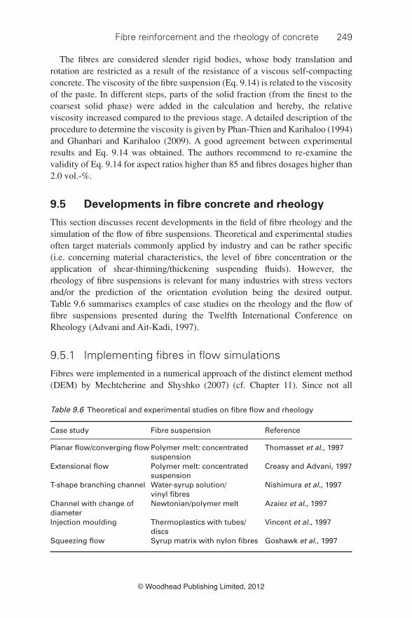
This section discusses recent developments in the fi eld of fi bre rheology and the simulation of the fl ow of fi bre suspensions. Theoretical and experimental studies often target materials commonly applied by industry and can be rather specifi c (i.e. concerning material characteristics, the level of fi bre concentration or the application of shear-thinning/thickening suspending fl uids). However, the rheology of fi bre suspensions is relevant for many industries with stress vectors and/or the prediction of the orientation evolution being the desired output. Table 9.6 summarises examples of case studies on the rheology and the fl ow of fi bre suspensions presented during the Twelfth International Conference on Rheology (Advani and Ait-Kadi, 1997).
9.5.1 Implementing fi bres in fl ow simulations
Fibres were implemented in a numerical approach of the distinct element method (DEM) by Mechtcherine and Shyshko (2007) (cf. Chapter 11 ). Since not all
Table 9.6 Theoretical and experimental studies on fi bre fl ow and rheology
Case study Fibre suspension Reference
Planar fl ow/converging fl ow Polymer melt: concentrated suspension
Thomasset et al., 1997
Extensional fl ow Polymer melt: concentrated suspension
Creasy and Advani, 1997
T-shape branching channel Water-syrup solution/ vinyl fi bres
Nishimura et al., 1997
Channel with change of diameter
Newtonian/polymer melt Azaiez et al., 1997
Injection moulding Thermoplastics with tubes/discs
Vincent et al., 1997
Squeezing fl ow Syrup matrix with nylon fi bres Goshawk et al., 1997

250 Understanding the rheology of concrete
© Woodhead Publishing Limited, 2012
particles could be modelled, the fl uid had to have model characteristics, which depend on the choice of rigid particles (size, shape and number). Rigid particles were considered to be suspended in a fl uid of defi ned characteristics. By clumping (connecting) smaller spheres long elongated fi bres could be modelled. The particle fl ow code ‘ITASCA’ was applied to execute the calculations. Positions and motions are transferred to forces and updated at each time step. With the defi nition of the characteristics of the contact elements, simulations (two- and three-dimensional) could be compared with specifi c fl ow situations such as the slump fl ow or fl ow through a V-funnel. The calibrated model was then applied to predict more complex fl ow processes such as mould fi lling or sprayed concrete. The quantitative analysis of the process still has to be executed and requires further verifi cation.
9.5.2 Verifying fl ow simulations with a non-destructive measuring technique
The measurement technique, impedance spectroscopy (IS), has been applied to determine the orientation and the distribution of the fi bres in cementitious materials (Woo et al. , 2005; Ferrara et al. , 2010). With this method, conductive steel fi bres were subjected to currents (direct or alternate current) at different frequencies. The resistance of the matrix at different locations and defi ned conditions is a measure of the dispersion of the fi bres. By executing measurements in different directions the orientation of the fi bres can be quantifi ed. The outputs of computational fl uid dynamics (CFD) simulations with the software package POLYFLOW were the orientation and the distribution of fi bres (Ferrara et al. , 2010). The results of fl ow simulations and IS measurements were compared and showed encouraging agreement.
9.5.3 Predicting fi bre orientation
Martinie and Roussel (2010) carried out fl ow simulations on the shear fl ow between two parallel plates. Model fl uids with only fi bres were implemented. Fibres with various initial orientations were considered to represent the macroscopic orientation process. Jeffrey’s equation (Eq. 9.11) was used to deduce the orientation evolution at different time steps. The orientation range was 0 to π and the yield stress of the concrete 50 Pa (self-compacting concrete) and 800 Pa (traditional vibrated concrete), respectively. The plastic viscosity was 80 Pa.s in each case. The fi bres oriented quickly along the walls in the concrete with the high yield stress. Orientation mainly occurred within a thin layer of paste sliding along the walls and differences in the orientation numbers were small ( Fig. 9.11 : left). In contrast, the fl ow of the concrete with a low yield stress caused a more preferred orientation ( Fig. 9.11 : right). The different fl ow patterns of both concrete types are refl ected by the differences in the average orientation number: 0.50 at a high and 0.71 at a low yield stress of concrete.

Fibre reinforcement and the rheology of concrete 251
© Woodhead Publishing Limited, 2012
9.6 Conclusions
The addition of fi bres can improve the performance of cementitious materials in the hardened state with regard to, for example, the tensile strength and crack width control. With an optimized mixture composition and controlled rheology and quality, fi bres can become more effective.
Due to the slender shape of the fi bres, aspects such as surface area, packing density and fi bre fl exibility have to be considered for the mix design. The critical fi bre content depends on the mixture composition and marks the maximum fi bre dosage at which, for example, self-compacting properties, a high workability or a homogenous fi bre distribution can be obtained. Fibres decrease the packing density, increase the surface area and/or contribute to the formation of a network and as a result rheological parameters like the yield value and the plastic viscosity are expected to increase. A more than proportional increase of these parameters can be prevented with an adequate mix design.
Signifi cant progress has been made during the past years on the fi eld of fl ow simulations and the rheology of fi bre suspensions. The main diffi culties are related to the non-Newtonian behaviour of fi bre suspensions (i.e. shear-thinning due to fi bre orientation and local fl ow-induced structures) and the diffi culty in predicting and measuring the different contributions of, for example, hydrodynamic effects and mechanical interaction. Fibre-reinforced cementitious materials are highly
9.11 Orientation factor relative to the fl ow direction z; yield stress of concrete, left: 800 Pa, right: 50 Pa (Martinie and Roussel, 2010).

252 Understanding the rheology of concrete
© Woodhead Publishing Limited, 2012
concentrated suspensions and it is not yet possible to model and to include all particles in simulations. However, with the progress in computer technology, measuring techniques and growing insight, fi bres could be considered a common rather than an additive component of cementitious materials.
9.7 References
Advani SG and Ait-Kadi A ( 1997 ), Editorial, Rheology and Flow of Fibre Suspensions, Symposium , 12th International Congress on Rheology, Quebec, Canada , Elsevier Science.
Ausias G , Fan XJ and Tanner RI ( 2006 ), ‘Direct simulation for concentrated fi bre suspensions in transient and steady state shear fl ows’ , Journal of Non-Newtonian Fluid Mechanics, 135 , 46 – 57 .
Azaiez J , Guénette R and Ait-Kadi A ( 1997 ), ‘Investigation of the abrupt concentration fl ow of fi ber suspensions in polymeric fl uids’ , Journal of Non-Newtonian Fluid Mechanics , 73 , 289 – 316 .
Banfi ll PFG ( 2003 ), ‘The rheology of fresh cement and concrete – a review’ , Proceedings 11th International Congress on the Chemistry of Cement, Grieve G and Owens G (eds.), Vol. 1 , Durban, South Africa , pp. 50 – 62 .
Banfi ll PFG , Starrs G , Derruau G , McCarter WJ and Chrisp TM ( 2006 ), ‘Rheology of low carbon fi bre content reinforced cement mortar’ , Cement and Concrete Composites , 28 , 773 – 780 .
Barnes HA , Hutton JF and Walters K ( 1989 ), An Introduction To Rheology , Amsterdam , Elsevier Science .
Barnett SJ , Lataste JF , Parry T , Millard SG and Soutsos MN ( 2010 ), ‘Assessment of fi bre orientation in ultra high performance fi bre reinforced concrete and its effect on fl exural strength’ , Materials and Structures , 43 , 1009 – 1023 .
Batchelor GK ( 1977 ), ‘The effect of Brownian motion on the bulk stress in a suspension of spherical particles’ , Journal of Fluid Mechanics , 83 , 97 – 117 .
Beaupré D ( 1994 ), Rheology of high performance shotcrete , Doctoral thesis, University of British Columbia , Vancouver, Canada .
Clarke B ( 1967 ), ‘Rheology of coarse settling suspensions’ , Transactions of the Institution of Chemical Engineers , 45 , 251 – 256 .
Creasy TS and Advani SG ( 1997 ), ‘A model long-discontinous-fi ber fi lled thermoplastic melt in extensional fl ow’ , Journal of Non-Newtonian Fluid Mechanics , 73 , 261 – 278 .
De Larrard F ( 1999 ), Concrete Mixture Proportioning: A Scientifi c Approach, London , E&FN Spon .
Einstein A ( 1906 ), ‘Eine neue Bestimmung der Moleküldimension’ [in German] , Annalen der Physik (Weinheim, Germany) , 19 , 289 – 306 .
Einstein A ( 1911 ), ‘Berichtigung zu meiner Arbeit: Eine neue Bestimmung der Moleküldimension’ [in German] , Annalen der Physik (Weinheim, Germany) , 34 , 591 – 592 .
Fan X-J , Phan-Tien N and Zheng R ( 1998 ), ‘A direct simulations of fi bre suspensions’ , Journal of Non-Newtonian Fluid Mechanics , 74 , 113 – 135 .
Ferrara L , Park YD and Shah SP ( 2007 ), ‘A method for mix-design of fi ber-reinforced self-compacting concrete’ , Cement and Concrete Research , 37 , 957 – 971 .
Ferrara L , Tregger N and Shah SP ( 2010 ), ‘Flow-induced fi ber orientation in SCSFRC: Monitoring and prediction’ , in Design, Production and Placement of Self-Consolidating

Fibre reinforcement and the rheology of concrete 253
© Woodhead Publishing Limited, 2012
Concrete , Khayat KH and Feys D (eds.), Dordrecht, RILEM Bookseries 1, pp. 417 – 428 .
Ghanbari A and Karihaloo BL ( 2009 ), ‘Prediction of the plastic viscosity of self-compacting steel fi bre reinforced concrete’ , Cement and Concrete Research , 39 , 1209 – 1216 .
Giesekus H ( 1983 ), ‘Disperse systems: dependence of rheological properties on the type of fl ow with implications for food rheology’ , in Physical Properties of Foods , Jowitt et al. (eds.), London , Applied Science , Chapter 13.
Goshawk JA , Navez VP and Jones RS ( 1997 ), ‘Squeezing fl ow of continuous fi bre-reinforced composites’ , Journal of Non-Newtonian Fluid Mechanics , 73 , 327 – 342 .
Groth P and Nemegeer D ( 1999 ), ‘The use of steel fi bres in self-compacting concrete’ , in First International Symposium on SCC , Stockholm , Skarendahl Å and Petersson Å (eds.), Cachan, RILEM Publications PRO 7, pp. 497 – 508 .
Grünewald S ( 2004 ), Performance-based design of self-compacting fi bre reinforced concrete , PhD thesis, Delft University of Technology, Department of Structural and Building Engineering, Delft University Press .
Grünewald S , Ferrara L and Dehn F ( 2010 ), ‘Structural design with fl owable concrete – a fi b-recommendation for tailor-made concrete’ , in Design, Production and Placement of Self-Consolidating Concrete , Khayat KH and Feys D (eds.), Dordrecht , RILEM Bookseries 1 , pp. 13 – 24 .
Holschemacher K and Dehn F ( 2002 ), ‘Faserbeton ein innovativer Baustoff auf dem Weg in die Zukunft’ [in German], in Faserbeton , König G , Holschemacher K and Dehn F (eds.), Berlin , Bauwerk Verlag , pp. 1 – 18 .
Jeffrey GB ( 1922 ), ‘The motion of ellipsoidal particles immersed in a viscous fl uid’ , Proceedings of the Royal Society of London, Series A , 102 , 161 – 179 .
Johnston CD ( 1996 ), ‘Proportioning, mixing and placement of fi bre-reinforced cements and concretes’ , in Production Methods and Workability of Concrete , Bartos PJM , Marrs DL and Cleland DJ (eds.), London , E&FN Spon , pp. 155 – 179 .
Keshtar M , Heuzey MC and Carreau PJ ( 2009 ), ‘Rheological behaviour of fi ber-fi lled model suspensions: effect of fi ber fl exibility’ , Journal of Rheology , 53 , 631 .
Khayat KH and Roussel Y ( 1999 ), ‘Testing and performance of fi ber-reinforced self-consolidating concrete’ , First International Symposium on SCC , Stockholm, Skarendahl Å and Petersson Å (eds.), Cachan, RILEM Publications PRO 7, pp. 509 – 521 .
Kitano T , Kataoka T and Shirota T ( 1981 ), ‘An empirical equation of the relative viscosity of polymer melts fi lled with various inorganic fi llers’ , Rheologica Acta , 20 , 207 – 209 .
Krage G and Wallevik OH ( 2007 ), ‘Rheology of synthetic-fi ber reinforced SCC’ , 5th International RILEM Symposium on Self-Compacting Concrete , Ghent/Belgium , Vol. 1 , pp. 347 – 352 .
Krieger IM and Dougherty TJ ( 1959 ), ‘A mechanism for non-Newtonian fl ow in suspensions of rigid spheres’ , Journal of Rheology , 3 , 137 – 152 .
Kristjánsson TI , Wallevik OH , Krage G and Nielsson I ( 2009 ), ‘Mix design for fi ber reinforced SCC’ , Third International RILEM Symposium on Rheology of Cement Suspensions such as Fresh Concrete , Reykjavik , RILEM Publications, pp. 322 – 327 .
Kuder KG , Ozyurt N , Mu EB and Shah SP ( 2007 ), ‘Rheology of fi ber-reinforced cementitious materials’ , Cement and Concrete Research , 37 , 191 – 199 .
Laranjeira F ( 2010 ), Design-oriented constitutive model for steel fi ber reinforced concrete , Doctoral thesis, Universitat Politécnica de Catalunya , Barcelona, Spain .
Laranjeira F , Grünewald S , Walraven J , Blom C , Molins C and Aguado A ( 2011 ), ‘Characterization of the orientation profi le of steel fi ber reinforced concrete’ , Materials and Structures , 44 , 1093 – 1111 .

254 Understanding the rheology of concrete
© Woodhead Publishing Limited, 2012
Laskar AI and Talukdar S ( 2008 ), ‘Rheology of steel fi ber reinforced concrete’ , Asian Journal of Civil Engineering , 9 , 167 – 177 .
Li V ( 2002 ), ‘Large volume, high-performance applications of fi bers in civil engineering’ , Journal of Applied Polymer Science , 83 , 660 – 686 .
Markovic I , Grünewald S , Walraven JC and Van Mier JGM ( 2002 ), ‘Characterization of bond between steel fi bres and concrete – conventional fi bre reinforced versus self-compacting fi bre reinforced concrete’ , Bond in Concrete – from Research to Standards, Third International Symposium , Budapest, Publishing Company of Budapest University of Technology , pp. 520 – 528 .
Martinie L and Roussel N ( 2010 ), ‘Fiber-reinforced cementitious materials: from intrinsic properties to fi ber alignment’ , in Design, Production and Placement of Self-Consolidating Concrete , Khayat KH and Feys D (eds), Dordrecht , RILEM Bookseries 1 , pp. 407 – 415 .
Martinie L , Rossi P and Roussel N ( 2009 ), ‘Rheology of fi ber reinforced cementitious materials: classifi cation and prediction’ , SCC 2008: 3rd North American Conference on the Design and Use of Self-Consolidating Concrete , pp. 465 – 469 .
Martinie L , Rossi P and Roussel N ( 2010 ), ‘Rheology of fi ber reinforced cementitious materials: classifi cation and prediction’ , Cement and Concrete Research , 40 , 226 – 234 .
Mechtcherine V and Shyshko S ( 2007 ), ‘Simulating the behaviour of fresh concrete using distinct element method’ , Fifth International RILEM Symposium on Self-Compacting Concrete , Ghent, Belgium , Vol. 1 , pp. 467 – 472 .
Nishimura T , Yasuda K and Nakamura K ( 1997 ), ‘Orientation behaviour of fi bers in suspension fl ow through a branching channel’ , Journal of Non-Newtonian Fluid Mechanics , 73 , 279 – 288 .
Pabst W , Gregorová E and Christoph C ( 2006 ), ‘Particle shape and suspension rheology of short-fi ber systems’ , Journal of the European Ceramic Society , 26 , 149 – 160 .
Petrie CJS ( 1999 ), ‘The rheology of fi bre suspensions’ , Journal of Non-Newtonian Fluid Mechanics , 87 , 369 – 402 .
Phan-Tien N and Karihaloo BI ( 1994 ), ‘Materials with negative Poisson’s ratio: a qualitative microstructural model’ , Journal of Applied Mechanics , 61 , 1001 – 1004 .
Philipse AP ( 1996 ), ‘The random contact equation and its implication for (colloidal) rods in packings, suspensions, and anisotropic powders’ , Langmuir , 12 , 1127 – 1133 .
Resplendino J ( 2011 ), ‘Introduction: What is a UHPFRC?’ , in Designing and Building with UHPFRC, Toutlemonde F and Resplendino J (eds.), London , John Wiley and Sons , pp. 3 – 14 .
Rossi P and Harrouche N ( 1990 ), ‘Mix design and mechanical behaviour of some steel-fi bre-reinforced concretes used in reinforced concrete structures’ , Materials and Structures , 23 , 256 – 266 .
Sedran T ( 1999 ), Rheologie et rheometrie des betons. Applications aux betons autonivelants [in French], PhD thesis, LCPC , Nantes .
Sepehr M , Carreau PJ , Moan M and Ausias G ( 2004 ), ‘Rheological properties of short fi ber model suspensions’ , Journal of Rheology , 48 , 1023 – 1048 .
Swamy RN ( 1975 ), ‘Fibre reinforcement of cement and concrete’ , Materials and Structures , 8 , 235 – 254 .
Swamy RN and Mangat PS ( 1974 ), ‘Infl uence of fi bre-aggregate interaction on some properties of steel fi bre reinforced concrete’ , Materials and Structures , 7 , 307 – 314 .
Tattersall GH ( 1991 ), Workability and Quality Control of Concrete , London , E&FN Spon .
Tattersall GH and Banfi ll PFG ( 1983 ), The Rheology of Fresh Concrete, London , Pitman .

Fibre reinforcement and the rheology of concrete 255
© Woodhead Publishing Limited, 2012
Thomasset J , Grmela M and Carreau PJ ( 1997 ), ‘Microstructure and rheology of polymer melts reinforced by long glass fi bres: direct simulations’ , Journal of Non-Newtonian Fluid Mechanics , 73 , 195 – 203 .
Vandewalle L ( 1993 ), ‘Fibre reinforced concrete – special types of concrete and applications’ , Katholieke Universiteit Leuven, Department Burgerlijke Bouwkunde, pp. 77 – 98 .
Vincent M , Devilers E and Agassant J-F ( 1997 ), ‘Fibre orientation calculation in injection moulding of reinforced thermoplastics’ , Journal of Non-Newtonian Fluid Mechanics , 73 , 317 – 326 .
Woo LY , Wansom S , Ozyurt N , Mu B , Shah SP and Mason TO ( 2005 ), ‘Characterizing fi ber dispersion in cement composites using AC-Impedance Spectroscopy’ , Cement and Concrete Composites , 27 , 627 – 636 .
Yamamoto S and Matsuoka T ( 1993 ), ‘A method for dynamic simulation of rigid and fl exible fi bers in a fl ow fi eld’ , Journal of Chemical Physics , 98 , 644 – 650 .
Yamamoto S and Matsuoka T ( 1995a ), ‘Dynamic simulation of fl ow-induced fi ber fracture’ , Polymer Engineering and Science , 35 , 1022 – 1030 .
Yamamoto S and Matsuoka , T ( 1995b ), ‘Dynamic simulation of fi ber suspensions in shear-fl ow’ , Journal of Chemical Physics , 102 , 2254 – 2260 .
Yamamoto S and Matsuoka T ( 1996 ), ‘Dynamic simulation of microstructure and rheology of fi ber suspensions’ , Polymer Engineering and Science, 36 , 2396 – 2403 .
Yamanoi M and Maia JM ( 2010 ), ‘Analysis of the rheological properties of fi bre suspensions in a Newtonian fl uid by direct fi bre simulation. Part 1: Rigid fi bre suspensions’ , Journal of Non-Newtonian Fluid Mechanics , 165 , 1055 – 1063 .
Yamanoi , M , Maia , JM and Tae-Soo , K ( 2010 ), ‘Analysis of the rheological properties of fi bre suspensions in a Newtonian fl uid by direct fi bre simulation. Part 2: Flexible fi bre suspensions’ , Journal of Non-Newtonian Fluid Mechanics , 165 , 1064 – 1071 .
Yu AB and Zou RP ( 1998 ), Prediction of the porosity of particle mixtures , Kona , 16 , 68 – 81 .
Yu AB , Standish N and McLean A ( 1993 ), ‘Porosity calculation of binary mixtures of non-spherical particles’ , Journal of the American Ceramic Society , 76 , 2813 – 2816 .
Zirnsak MA , Hur DV and Boger DV ( 1994 ), ‘Normal stresses in fi ber suspensions’ , Journal of Non-Newtonian Fluid Mechanics , 54 , 153 – 193 .
Zou RP and Yu AB ( 1996 ), ‘Evaluation of the packing characteristics of mono-sized non-spherical particles’ , Powder Technology , 88 , 71 – 79 .
9.8 Appendix: notations and symbols
D rate of strain tensor E E-modulus (MPa) L f fi bre length (mm) N number of fi bres (-) N sf number of steel fi bres (-) V f fi bre volume (Vol.%) W vorticity tensor d grain diameter (mm) d f fi bre diameter (mm) d p equivalent packing diameter (mm)

256 Understanding the rheology of concrete
© Woodhead Publishing Limited, 2012
d v volume diameter (mm) f fi bre fl exibility (mm 4 ) g parameter correlated with yield value (Nm) h parameter correlated with viscosity (Nm·s) k f wall-effect fi bres (-) n number of fi bres per unit volume (-) p unit vector r aspect ratio: L f /d f (-) r i component of the position vector of the centroid in deformed confi guration v p perturbed volume in a container (Vol.%) φ volume fraction of solids/fi bres (Vol.%) φ c solid volume (loose packing) (Vol.%) φ cf critical fi bre volume (Vol.%) φ f percentage of fi bres of the granular skeleton (Vol.%) φ m solid volume (dense packing) (Vol.%) Φ phase volume of solids (Vol.%) Φ f volume fraction of fi bres (Vol.%) Φ fc random loose packing fi bres (-) Φ fm random dense packing fi bres (-) Φ ms dense packing fraction sand (-) Φ s volume fraction of sand (Vol.%) α unperturbed packing density (-) α– mean packing density (affected by the container size) (-) αc packing density parameter, loose packing (-) α →
d average orientation number (-)
α m packing density parameter, dense packing (-) γ͘ shear rate (1/s) ε 0d,cyl dense (experimental) packing density of fi bres (-) η viscosity (Pa·s) (η) intrinsic viscosity (-) η e plastic viscosity of mix with fi bres (Pa·s) η s viscosity of suspending fl uid (Pa·s) λ parameter dependent on r µ plastic viscosity Bingham model (Pa·s) σ standard deviation σ ij stress tensor of viscous suspension ( σ ij ) m stress tensor matrix ( σ ij ) f stress tensor fi bres t shear stress (Pa) τ 0 yield value (Pa) ψ sphericity (-)