fiber lasers: fundamentals and applications · 2017-05-19 · nonlinear photonics and high 1...
TRANSCRIPT

Nonlinear
Photonics
and High
1
Lecture 6
V R Supradeepa
Center for Nano Science and Engineering (CeNSE)
Indian Institute of Science
Fiber Lasers: Fundamentals
and Applications

Lasers for Directed energy
• High energy military lasers used in weapon systems
• “Introduction of energy weapons is a game changer comparable to missiles, aircraft carriers and GPS technology” -Navy League Exposition 2013
• 2013- US Navy to deploy first laser on a ship capable of disabling an aircraft
• Competing technologies: Free Electron (FEL) and Solid State Slab lasers
2
LAWS Short Range Laser System
Requirements
50kW – 100kW class Lasers
necessary
Excellent beam quality and
pointing stability
Nonlinear Photonics and High Power Lasers Laboratory, CeNSE, IISc 2

3
Limits of power scaling
• The limits of single mode output power from a fiber laser is
expected to be ~ 10kW (J. W. Dawson et al, IEEE Leos 2008 )
• Limited by effects such as optical damage, core melting,
thermal lensing, thermal rupture etc
• Single mode CW fiber lasers with output power
of upto 10kW has been demonstrated
• More akin to power combing, multiple fiber
laser modules pumping a large-mode area
double clad fiber)
• Practically, individual single mode fiber laser
modules have power levels in the level of 2-3kWIPG
Nonlinear Photonics and High Power Lasers Laboratory, CeNSE, IISc

4
Overcoming power scaling limitations
• Power combining needs to enhance brightness. Broadly divided into
• Coherent beam combining
• One spatial mode and one spectral mode
• Spectral beam combining
• One spatial mode but multiple spectral modes
Nonlinear Photonics and High Power Lasers Laboratory, CeNSE, IISc 4

5
Coherent Combining
5
All laser sources originating from
the same seed source (same
common mode noise)
Why narrow linewidth – path length
accuracy needs to be significantly
better than coherence length
Tiled Aperture Filled Aperture
DOE
Different
Orders
Pros Cons
• Single seed source • Complex system and control
• Degradation not graceful on
individual module failure

6
Wavelength Combining
6
Pros Cons
• Simplified control system
• Graceful degradation
• Multiple seed sources locked
to wavelength grid
Individual seed laser sources
locked precisely in wavelength
Why narrow linewidth – Angular
spread due to Diffraction effects
needs to be small within each
channel
Nonlinear Photonics and High Power Lasers Laboratory, CeNSE, IISc
Diffraction
Grating

Power Combinable Fiber Lasers
Nonlinear Photonics and High Power Lasers Laboratory, CeNSE, IISc 7

8
General Requirements
Nonlinear Photonics and High Power Lasers Laboratory, CeNSE, IISc 8
• High gain single stage amplifier (15-dB +)
• To minimize system complexity
• Power handling of standard isolators decided need for Gain
• High output power per amplifier module
• Higher the power, the better
•linewidth of < 10GHz at 1kW
• Power linewidth compromise
•M2 ≤ 1.1
• h 75%
• Preferably Linearly Polarized Architecture (PER > 13dB)

9
Module Schematic
Nonlinear Photonics and High Power Lasers Laboratory, CeNSE, IISc 9
Seed Source
Power Amplifier

10
Nonlinear Limitations
Key limiting factors
• Stimulated Brillouin scattering
• Modal instability (Stimulated thermal Rayleigh scattering)
• Thermal waveguide degradations
Nonlinear Photonics and High Power Lasers Laboratory, CeNSE, IISc 10

Stimulated Brillouin Scattering
Nonlinear Photonics and High Power Lasers Laboratory, CeNSE, IISc 11

12
Stimulated Brillouin Scattering
16GHz
50MHz
Frequency
• Narrow gain bandwidth ~
50MHz
• Reducing optical intensity
reduces SBS
Frequency
1B
fEF
Enhancement
factor
Nonlinear Photonics and High Power Lasers Laboratory, CeNSE, IISc 12

13
Design of SBS compensated Laser Modules
Nonlinear Photonics and High Power Lasers Laboratory, CeNSE, IISc 13
Anticipated linewidth as a function of fiber MFD at 1kW

Modal Instability
Nonlinear Photonics and High Power Lasers Laboratory, CeNSE, IISc 14

15
Modal Instability
• Coherent phenomenon occuring
primarily in narrow linewidth fiber
lasers with multimoded behavior.
• Due to differential heat load in the
coherent interference pattern
between different modes, thermo-
optic grating forms.
(From Jena)
Collection of LP01
and LP11 modes in
a fully doped core
Converts to a
thermooptic
“long period
grating”
15

Modal Instability
0 1 2 3 40
10
20
30
40
50
60
70
Length (m)
Cu
mu
lati
ve g
ain
(d
B)
30um core, 250um cladding, Similar
pump absorption, No LP11 loss
Small signal gain
versus pump
power
@ 1.2kW
LP11 gain
(thermo-optic)
From A. V. Smith et
al (Optics express)
• Failsafe option to suppress
modal instability – Loss for higher
order mode > Nonlinear gain
• Highly single-moded LMA fibers
necessary
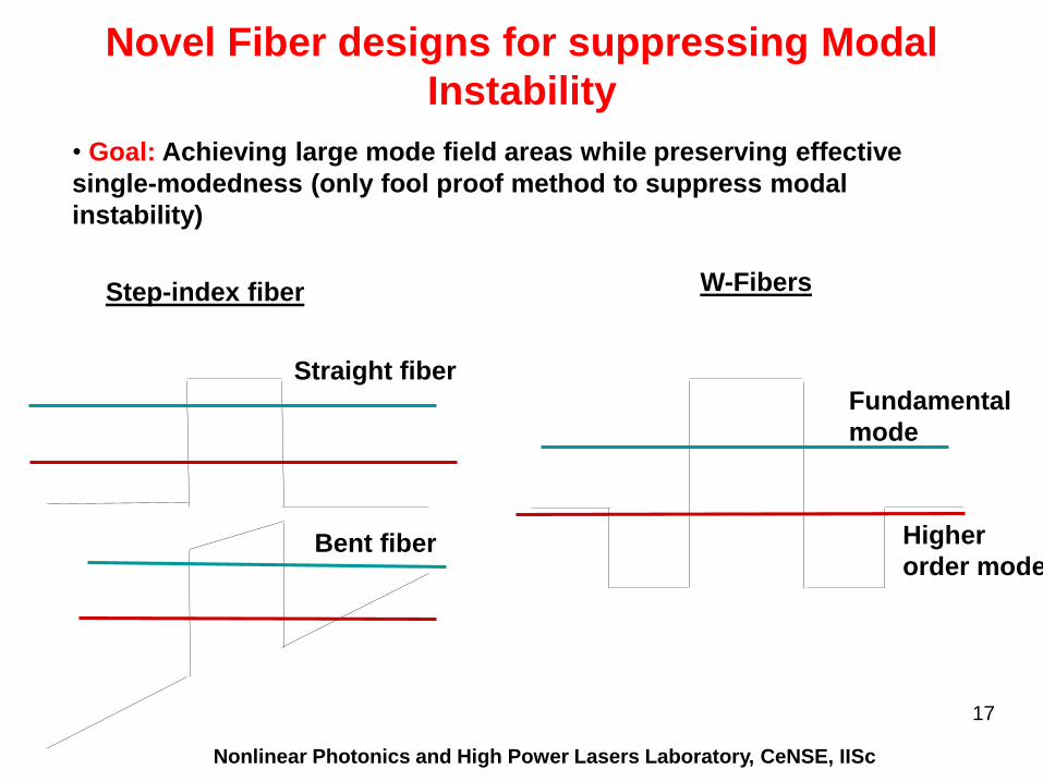
Novel Fiber designs for suppressing Modal
Instability
W-Fibers
• Goal: Achieving large mode field areas while preserving effective
single-modedness (only fool proof method to suppress modal
instability)
Fundamental
mode
Higher
order mode
Step-index fiber
Straight fiber
Bent fiber
Nonlinear Photonics and High Power Lasers Laboratory, CeNSE, IISc
17

Novel Fiber designs for suppressing Modal
Instability
• Confined Doping
Nonlinear Photonics and High Power Lasers Laboratory, CeNSE, IISc
18
Core index enables large mode area
Confined doping reduces overlap with higher order modes

Thermal Waveguide Degradations
Nonlinear Photonics and High Power Lasers Laboratory, CeNSE, IISc 19

20
Loss of single modedness in active fibers
20

Compensation Mechanisms for thermal waveguide
degradations
Goal
• Simple and elegant methods to overcome thermal waveguide
degradations
Supradeepa et al, CLEO 2015, Optics Express (Submitted)
10 15 20 2510
-3
10-2
10-1
100
101
102
Additional Bend Diameter (cm)
Ben
d L
oss (
dB
/m)
L = 3mL = 0.5mL = 1mL = 0m

Narrow Linewidth Laser Module
Nonlinear Photonics and High Power Lasers Laboratory, CeNSE, IISc 22
23
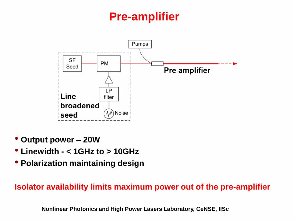
Pre-amplifier
Nonlinear Photonics and High Power Lasers Laboratory, CeNSE, IISc
• Output power – 20W
• Linewidth - < 1GHz to > 10GHz
• Polarization maintaining design
Isolator availability limits maximum power out of the pre-amplifier

24
Line Broadening
Nonlinear Photonics and High Power Lasers Laboratory, CeNSE, IISc
Necessary Linewidths –
Coherent combining – GHz class linewidths (< 0.04nm) corresponds to
path length accuracies of several mm.
• Achievable in practice.
• Lower linewidths than this – largely unnecessary
Spectral combining – Intrachannel spectral dispersion needs to be
low, intra-channel spectral dispersion needs to be high.
• Assuming 50 channels in high Yb gain bandwidth of 25nm,
corresponds to channel spacing of 0.5nm. Desired, linewidth
less than 10% of that < 0.05nm
• With increasing number of channels, this scales appropriately

25
Line Broadening Mechanisms
Nonlinear Photonics and High Power Lasers Laboratory, CeNSE, IISc
• Sinusoidal tones –
• Strongly driving a phase modulator with sinusoids.
• Results in uneven lines, SBS suppression per spectral width not
optimal
• Chirp –
• Works well for small bandwidths, but not GHz class
• Filtered Noise –
• Easy to implement, most common
• Results in length dependent effects

26
Line Broadening with Noise – Length dependent
effects
Lb ~ 4m, Length scale originating from
Brillouin gain bandwidth
• Short length effects need to be compensated
• Goal - Suppressing SBS in the systems perspective (SBS as a signal
processing problem)
Nonlinear Photonics and High Power Lasers Laboratory, CeNSE, IISc 26
V R Supradeepa,
Optics Express (2013)

27
Amplifier architecture
• Fiber – Effectively single-moded with MFD > 15micron
• Delivery fiber need not be the same – can be bigger (needs
tapered splice)
• Polarization maintaining – PANDA design
Nonlinear Photonics and High Power Lasers Laboratory, CeNSE, IISc

Pump diodes
Mode converter +
Cladding mode stripper TFB
Gain fiber
Amplifier Module: Layout

29
Setup and Characterization (Testbench)
Nonlinear Photonics and High Power Lasers Laboratory, CeNSE, IISc