fib mumbai prima pag. - tecnochem.it larger than 60–70 mm (fib bulletin 24, 2003) due to the...
TRANSCRIPT


STRUCTURAL REINFORCEMENT
AND SEISMIC RETROFITTING WITH UHPFRCC
SPECIAL FORMULATION JACKETING
OF 1930 BUILDING R.C. STRUCTURAL ELEMENTS
Dario Rosignoli, Tecnochem Italiana SpA, Italy
Francesco Rosignoli, Tecnochem Italiana SpA, Italy
Giovanni Martinola, Tecnochem Italiana SpA, Italy
Stefano Maringoni, Tecnochem Italiana SpA, Italy
Serena Mostosi, Tecnochem Italiana SpA, Italy
Abstract
A very large tobacco factory was transformed into a residential building. A new technology using
UHPFRCC (Ultra High Performance Fiber Reinforced Cementitious Composites) was utilized to
improve ductility and bearing capacity of the old building. A seismic retrofitting of beams, columns
and nodes was successfully performed avoiding the use of stirrups and steel bars.
This solution was promoted by the project engineers and the contractor as alternative to a standard
RC jacket in order to reduce time and costs. The performance of the proposed solution has been
investigated on a full-scale column test subjected to a cyclic load.
Keywords : UHPFRCC – Seismic retrofitting – Ductility – Fracture energy
1 Introduction
In recent years the strengthening and the repair of existing RC structures have been among the most
important challenges in civil engineering. The primary reasons for strengthening of structures
include: upgrading of resistance to withstand underestimated loads; increasing the load bearing
capacity for higher permissible loads; meet the requirements in seismic areas where older
construction were not designed for earthquake impacts; restoring lost load bearing capacity due to
corrosion or other types of degradation caused by aging, etc.
Different techniques have been developed to retrofit a variety of structural deficiencies. The
techniques traditionally used, based on externally bonded steel plates or RC jacketing, have many
limitations. In particular, the use of RC jackets is possible by adding layers of concrete with
thicknesses larger than 60–70 mm (Fib Bulletin 24, 2003) due to the presence of rebars requiring a
minimum concrete cover, thus leading to an excessive increase of the section geometry. The main
disadvantage of using steel plates is corrosion of steel which adversely affects the bond at the steel
concrete interface. A solution that has recently gained favour concerns the use of externally bonded
Fiber Reinforced Polymers (FRP). Unfortunately, this techniques may not satisfy minimum
requirements for serviceability limit states and could have problems with fire resistance.
Recently, FRC materials showing a hardening behaviour in tension, usually named High
Performance Fiber Reinforced Concrete (HPFRC), are available for practical use and allow new
applications. In fact, by using these materials, it is possible to design structures with new
geometries and shapes that are no longer limited by the reinforcement detailing limitations. One of
the most promising area of applications of this material is in the repair of concrete structures. The
HPFRC materials offer the possibility of developing thin cement-based composite sheets for
structural retrofit and they are suitable for repairing concrete structures due to their compatible
mechanical and physical properties.

In this project, the new strengthening technique that involves the use of thin high performance
jackets for retrofitting RC structural members, has been applied to a real building. The first part of
the paper shows the experimental research carried out to confirm the effectiveness of this
strengthening technique. Two full scale experimental cyclic tests on column specimens and five
four point bending tests on beams using high performance jackets have been performed. In the
second part of the project a new technology with UHPFRCC was used on an industrial building
(ex tobacco factory), that was built in 1929, to improve the load bearing capacity and the seismic
behaviour of the RC structural members.
2 Material properties of UHPFRCC
The UHPFRCC used in this project presents an almost self levelling rheology. Moulded specimens
reach a compressive strength of 130 MPa and a tensile strength of 8,5 MPa. Direct tensile tests on
dog bone specimens and four point bending tests on small beams were performed in order to
characterize the material in tension. The results of the four point bending tests together with the
specimen geometries are given in Fig. 1. The results of the tests show the tensile strain hardening
behaviour of the material. The physical and mechanical properties of the high performance fiber
reinforced concrete are listed in Table 1.
Fig. 1 Material characterization: flexural tests
(100x100 mm cross-section).
Table 1. Physical and mechanical properties of
UHPFRCC
3 Experimental research
3.1 Strengthening RC columns
Two full-scale experimental cyclic tests on column specimens have been performed. The columns
have a height of 3 m and a cross section of 350x350 mm. The two columns used for testing were
extracted from a part of the ex tobacco factory that has been demolished. A foundation has been
cast to allow the anchoring of the specimens to the test frame. The two columns have the same
section but different longitudinal reinforcement.
One column was reinforced with a traditional jacket with a thickness of 60 mm, 12∅14
longitudinal rebars and 8mm stirrups spaced at 100mm for a height of one meter from the
foundation. The second column was strengthened by a high performance fiber reinforced jacket
with a thickness of 40 mm. The tests were done applying an axial load equal to 60 kN and
horizontal load with cycles characterized by an increasing amplitude up to failure. The
experimental setup defines three fully reversed cycles at each drift level.
Fig. 2 shows the resulting load versus displacement curves for all specimens. For the columns
with a traditional RC jacket the test was stopped after the execution of the cycles corresponding to
a drift of 2% after which cover spalling and concrete crushing occurred at the column base for a
height approximately equal to the edge length. Additionally, deformation of the reinforcing bars
0
5
10
15
20
25
30
35
40
45
0 1 2 3 4 5 6 7Mid-span displacement [mm]
Lo
ad
[kN
]
Workability ≥ 1 h
Density 2450 Kg/m3
Compression strength 130 MPa
Tensile strength 8,5 MPa
Flexural strength 32 MPa
Shear strength 16 MPa
Elastic modulus 38 GPa
Fracture energy 32500 N/m
Shrinkage < 0,05 %
Carbonation depth 0
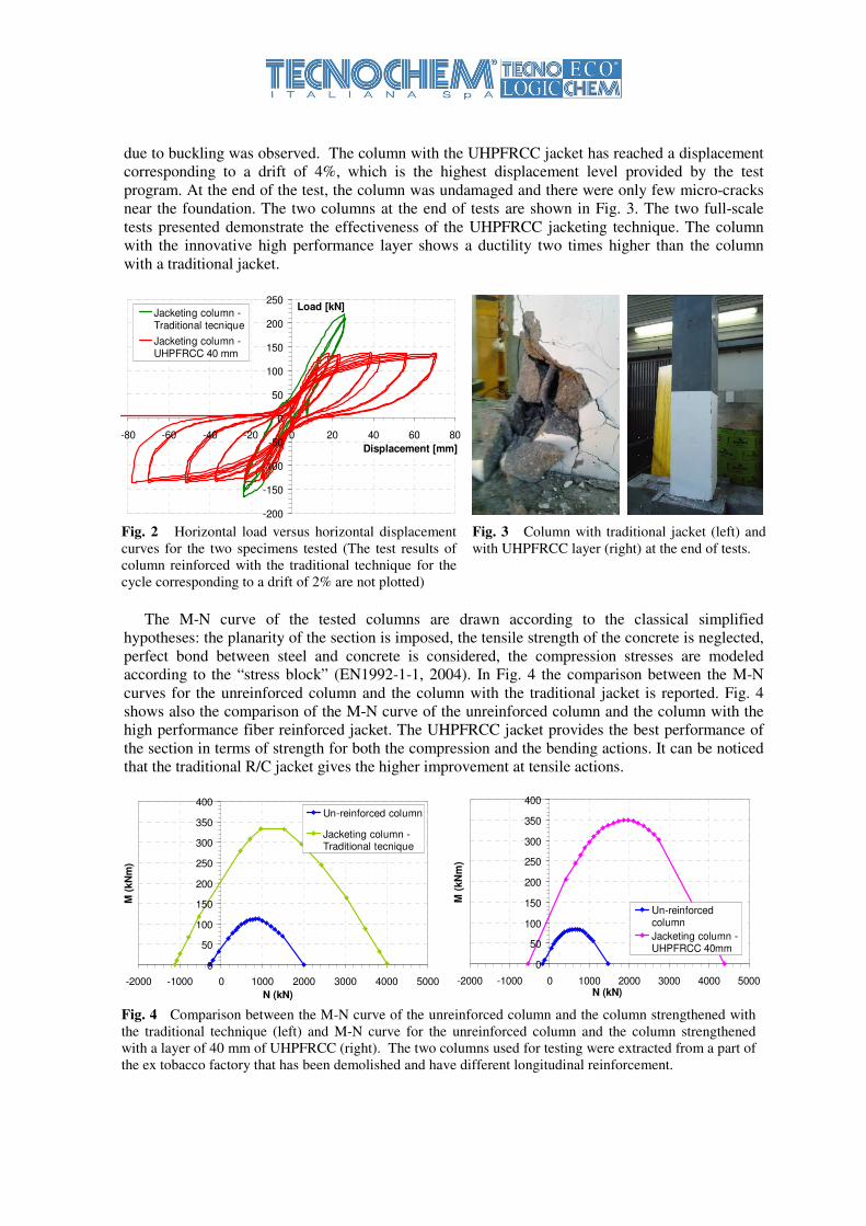
due to buckling was observed. The column with the UHPFRCC jacket has reached a displacement
corresponding to a drift of 4%, which is the highest displacement level provided by the test
program. At the end of the test, the column was undamaged and there were only few micro-cracks
near the foundation. The two columns at the end of tests are shown in Fig. 3. The two full-scale
tests presented demonstrate the effectiveness of the UHPFRCC jacketing technique. The column
with the innovative high performance layer shows a ductility two times higher than the column
with a traditional jacket.
-200
-150
-100
-50
0
50
100
150
200
250
-80 -60 -40 -20 0 20 40 60 80
Displacement [mm]
Load [kN]Jacketing column -Traditional tecnique
Jacketing column -UHPFRCC 40 mm
\
Fig. 2 Horizontal load versus horizontal displacement
curves for the two specimens tested (The test results of
column reinforced with the traditional technique for the
cycle corresponding to a drift of 2% are not plotted)
Fig. 3 Column with traditional jacket (left) and
with UHPFRCC layer (right) at the end of tests.
The M-N curve of the tested columns are drawn according to the classical simplified
hypotheses: the planarity of the section is imposed, the tensile strength of the concrete is neglected,
perfect bond between steel and concrete is considered, the compression stresses are modeled
according to the “stress block” (EN1992-1-1, 2004). In Fig. 4 the comparison between the M-N
curves for the unreinforced column and the column with the traditional jacket is reported. Fig. 4
shows also the comparison of the M-N curve of the unreinforced column and the column with the
high performance fiber reinforced jacket. The UHPFRCC jacket provides the best performance of
the section in terms of strength for both the compression and the bending actions. It can be noticed
that the traditional R/C jacket gives the higher improvement at tensile actions.
0
50
100
150
200
250
300
350
400
-2000 -1000 0 1000 2000 3000 4000 5000
N (kN)
M (
kN
m)
Un-reinforced column
Jacketing column -Traditional tecnique
0
50
100
150
200
250
300
350
400
-2000 -1000 0 1000 2000 3000 4000 5000N (kN)
M (
kN
m)
Un-reinforcedcolumn
Jacketing column -UHPFRCC 40mm
Fig. 4 Comparison between the M-N curve of the unreinforced column and the column strengthened with
the traditional technique (left) and M-N curve for the unreinforced column and the column strengthened
with a layer of 40 mm of UHPFRCC (right). The two columns used for testing were extracted from a part of
the ex tobacco factory that has been demolished and have different longitudinal reinforcement.

3.2 Strengthening RC beams
This research (Meda et al. 2012 ) used an UHPFRCC jacket for strengthening or repair of RC
beams. The effectiveness of shear reinforcement technique was studied through five beam
specimens with a length of 2.85 m and rectangular transverse section characterized by a width of
200 mm and a depth of 500 mm. The specimens have been tested at a four point bending
configuration. The beams have been reinforced with longitudinal bottom rebars only and were
designed in order to have a shear failure under the chosen load configuration. Neither stirrups nor
inclined reinforcement are present. One beam was used as reference specimen while the other four
beams were strengthened by a high performance jacket with different thicknesses.
Fig. 5 shows the load versus mid-span displacement of the five beams tested and the different
thicknesses of the UHPFRCC layers.
Fig. 5 Load versus mid-span displacement for shear beams.
The tests demonstrate the effect that the UHPFRCC jackets have on the collapse mode, as well
as on the post-cracking behaviour, and on crack formation and evolution. Contrary to the reference
beam, all jacketed beams fail in bending, with limited shear effects. Fig. 6 shows the comparison of
the crack patterns of the unreinforced beam and the beam SA with a with a UHPFRCC jacket of 30
mm. UHPFRCC layers allow to increase the load bearing capacity of the beam. For beams SB and
SC (50 mm jacket), as well as for beam SA (30 mm jacket), the capacity is 1.7 times higher, while
for beam SD (30 mm jacket along the lateral sides and 50 mm jacket on the bottom surface) the
increase of the capacity is smaller (1.5 times). The proposed technique allows also to increase the
structural stiffness significantly, as shown by the mid-span displacements, which are greatly
reduced for the same load level, before the peak load.
Additionally, the unreinforced beam shows a brittle failure (shear-type failure) while the four
jacketed beams show a very ductile failure, which is demonstrated by their post-peak behaviour
with rather stable softening.
Fig. 6 Crack distribution at the end of test for the reference beam (left) and for the beam SA with a HPFRC
jacket of 30 mm (right).
Bottom surface 30 mm BEAM
SA Lateral surface 30 mm
Bottom surface 50 mm BEAM
SB Lateral surface 50 mm
Bottom surface 50 mm BEAM
SC Lateral surface 50 mm
Bottom surface 50 mm BEAM
SD Lateral surface 30 mm
0
100
200
300
400
500
600
700
800
0 5 10 15 20 25 30 35Displacement
Lo
ad
0
25
50
75
100
125
150
175
0 0.2 0.4 0.6 0.8 1 1.2
Beam SABeam SBBeam SCBeam SDBeam SR
[mm]
[kN] [kips] [inches]
4 Description of the building and diagnostic
An application of this new strengthening technique to a real case is presented here: an industrial
building (ex tobacco factory) located in the municipality of Milan (Italy). The building was built in
1929 and it has a reinforced concrete structure cast in situ. The building has a structure consisting
of two symmetrical bodies, named "South Wing" and "North Wing". Each body consists of a L-
shaped floor plan, formed by three separate units connected by structural joints, each of which has
four floors above ground and a basement. The main structure in reinforced concrete is
characterized by a regular structural mesh. The plain type is realized by a system of lowered main
beams with a regular mesh by steps of 682 cm and a system of lowered secondary beams that rely
on the system of the main beams. The ground floor consists of a full slab 25 cm thickness with
localized markdowns near the columns to contain the action of punching. The type floor is made
from a solid slab of reinforced concrete with variable thicknesses of 12-13-15 cm. Fig. 7 shows the
view of the building and the reinforced concrete structure.
Fig. 7 Aereal view of the building on which the intervention was carried out (left) and view of the building
structure in which one can see the system of main and secondary beams (right).
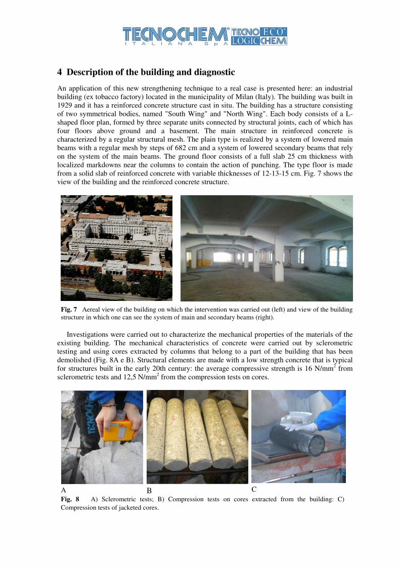
Investigations were carried out to characterize the mechanical properties of the materials of the
existing building. The mechanical characteristics of concrete were carried out by sclerometric
testing and using cores extracted by columns that belong to a part of the building that has been
demolished (Fig. 8A e B). Structural elements are made with a low strength concrete that is typical
for structures built in the early 20th century: the average compressive strength is 16 N/mm2 from
sclerometric tests and 12,5 N/mm2 from the compression tests on cores.
A B
C
Fig. 8 A) Sclerometric tests; B) Compression tests on cores extracted from the building: C)
Compression tests of jacketed cores.

Reinforcing rebars are smooth and were classified as steel type AQ38. This type of steel was
used at the time of construction of the building and it has mechanical characteristics similar to steel
FeB22k according to Italian codes (yield strength ≥ 215 MPa and maximum strength ≥ 335 MPa).
In situ the average maximum strength has been experimentally measured and it has a value equal to
380 MPa.
Additional tests were conducted on cores extracted from the building and then jacketed with a
thickness of UHPFRCC of 20 mm (Fig. 8C). The results of the compression tests on these
specimens show a strength of 30 N/mm2 at 7 days after the application of the jacket and a strength
of 36 N/mm2 28 days after the application of the jacket.
An analysis of the building shows that the structural elements have been designed and arranged
without taking into account the action of horizontal forces (neither the action of the earthquake nor
that of the wind) but making reference only to vertical loads.
The analysis carried out on the existing building shows that several columns and beam-column
joints of the building do not satisfy the requirements imposed by current codes and therefore it is
necessary to intervene with an operation of jacketing to increase the resistance under the
combination of compressive and bending actions of structural elements.
5 The execution project
The ex tobacco factory has been transformed to a residential building. The intervention is designed
to adapt the building to the level of safety provided by existing Italian rules.
The proposed intervention involves the use of high-performance concrete, characterized by a
high compression strength and an elasto-plastic tensile behaviour. These features allow the use of
these materials without introducing traditional reinforcement.
The project was carried out taking into account the seismic actions of the Italian codes provided
for the Municipality of Milan, where the building is located. In particular, the building has been
subjected to an intervention which involves the safety in respect of the loads that are not seismic
(gravitational actions and wind) and improvement in respect of the seismic combination of loads.
A considerable advantage of the technique of intervention proposed is the possibility to realize
jacket with reduced thickness introducing limited changes to the geometry of the building. In
comparison to a jacketing made with a traditional technique (jacketing with reinforced concrete)
this intervention allows a considerable reduction of the mass of the structure.
In the following paragraphs verifications performed on a column and on a beam-column joint
strengthened with a UHPFRCC jacket with a thickness of 40 mm are shown.
5.1 Columns verification
The M-N curves for the strengthened columns have been calculated using a bond of the concrete
type "stress-block" (Fig. 9) and following the classical simplified hypotheses reported in paragraph
3.1. The calculations were carried out without considering the concrete cover, in either direction of
the section.
Fig. 9 Diagram of the strains and stresses at the ultimate limit state on the reinforced section.
concrete UHPFRCC

An example of verification of a column (column 1D) is shown here. In Fig. 10A the geometrical
characteristics of the column object of the verification are shown and in Fig. 10B the location of the
column within the structural mesh of the building is reported. Fig. 10C shows the M-N curve for
the strengthened section of the column for the x direction and the y direction. This example of M-N
curve is relative to the section of the third / fourth floor called P12/G2.
Fig. 10 A) Geometrical characteristics of the column 1D; B) Configuration of the south wing; C) M-N curve
for the strengthened section of the column 1D for the x direction and the y direction.
5.2 Beam-column joint verification
According to the instructions to the new Italian code [Instructions DM2008, 2009], the strength
verification of the unretrofitted beam-column joint may be performed as follows:
σ
= − + ≤
2 2
0.32 2
n
nt ck
g g g
VN Nf
A A A (1)
Where:
� Ag is the column section
0 1 106
× 2 106
× 3 106
×
1 105
×
2 105
×
3 105
×
Pilastro 1D P12,G2 direzione y
N [N]
M [
N m
]
0 1 106
× 2 106
× 3 106
×
5 104
×
1 105
×
1.5 105
×
2 105
×
Pilastro 1D P12,G2 direzione x
N [N]
M [
N m
]
THIRD/ FOURTH FLOOR
1D COLUMN
Column 1D, P12,G2, y direction
Column 1D, P12,G2, x direction
A
B
C

� Vn is the total shear acting on the joint (difference between the tensile stress in the traditional
reinforcement and the shear on the upper column)
= − ⋅ −,sup ,inf
( )n s s yd SdV A A f V
� N is the axial load in the upper column
For the retrofitted nodes, eq. 1 may be modified to account for the tensile strength contribution of
the UHPFRCC jacket as follows:
γ
σ
⋅ + ⋅
= − + ≤
,2 2 0.3 '
2 2
tk HPFRC
ck g g
HPFRCn
nt
T T T T
ff A A
VN N
A A A A (2)
Where:
� 'T g g
A A A= +
� Ag is the area of the section of the non retrofitted column
� A’g is the area of the UHPFRCC applied to the column
� γHPFRC is the safety factor for UHPFRCC
� Ftk,HPFRC is the tensile strength of UHPFRCC
The verification of the beam-column joint for the column 1D at the level of the last floor is as
follows. With an axial load of 319 kN the stress in the joint derived from equation 2 is equal to
1.71 MPa, which is smaller than the joint strength equal to 2.71 MPa. In this case, the joint strength
verification is satisfied.
6 Application of the UHPFRCC jacket
Before the casting of the jacket, the structural elements on which the reinforcement will be applied
were hydro-jetted in order to obtain a roughness of about 1 mm, in order to ensure perfect bond
between the existing concrete and the applied high performance concrete. Fig. 11 shows the
treatment of hydro-jetting of the structural elements and, in detail, the concrete surface after the
treatment. Immediately before casting the surface of the elements has been saturated with water to
ensure better adhesion between the substrate and the material used for the reinforcement.
Fig. 11 Hydro-jetting of the structural elements (left) and surface after the treatment (right)
The UHPFRCC material was prepared in a vertical axis mixers and the self levelling concrete
was cast in moulds (Fig. 12A) without vibration. The application of the UHPFRCC jacket has been
performed in two phases: in the first phase the casting of the column up to the base of the node has
been executed, in the second phase the jacket of the beams and the nodes has been casted. Within
the high performance jacket rebars for a length of one meter above and one meter below the level
of the floor have been inserted. The purpose of these reinforcement bars is to ensure continuity

between the castings of the UHPFRCC jacket between the various floors of the building and also to
improve the ductility and thus the seismic behaviour of the beam-column joints.
To perform the cast of the jacket of the beams holes in the floor slabs were done through which
it is possible to cast the material into the moulds. Near the supports of the beams, where there is the
maximum shear stress, U bent steel bars were positioned at the upper side. The function of these
bars is to form equivalent stirrups to further improve the shear behaviour of the beams jacketed.
A
B
C
Fig. 12 A) Mould used for the cast of a jacket of a column; B) Beam-column joint reinforced with the
UHPFRCC jacket; C) View of the structural elements after the application of the strengthened jacket.
The moulds were removed approximately 24 hours after the cast of the high performance jacket
and a plastic sheet was placed on the surfaces in order to limit water evaporation. Fig. 12B and Fig.
12C show the final view of the structural elements after the application of the high performance
fiber reinforced jacket.
6 Conclusions
In the first part of the project the use of UHPFRCC layers for strengthening R/C structural
members has been investigated by means of full-scale tests. Two full-scale experimental cyclic
tests on column specimens have been performed. The results confirm the effectiveness of this
technique. With the application of a high performance jacket it was possible to increase the load
bearing capacity of the column compared to the unreinforced specimen. The comparison between
the new strengthening technique and a traditional R/C jacket shows that the use of UHPFRCC
layers significantly increase the ductility of the columns and the seismic response of the structure.
The use of a UHPFRCC jacket has also been studied for strengthening RC beams. The application
of a high performance jacket provides a sizable increase in both the load bearing capacity and the
stiffness in R/C beams.
In the second part of the project the new technology with UHPFRCC was applied on a real
industrial building for a retrofitting intervention for static load and for improving the seismic
performance of the building. In comparison to the traditional jacketing technique the use of the
UHPFRCC jackets allows the realization of interventions of reduces thickness with considerable
advantages in terms of a limited impact on the geometry of the building and in terms of the
reduction of the dead load of the structural elements. The use of this new technique also ensures a
considerable reduction on the time of application. The high fluidity of the material allows to have
very smooth surfaces, without the outcrop of fibers, which may also not be plastered, reducing even
more the impact of the intervention. Finally, the application of a high performance fiber reinforced
jacket ensures a high protection regarding durability.

References
Alaee, F.J., Karihaloo, B.L. (2003) Retrofitting of reinforced concrete beams with CARDIFRC.
Journal of Composite Construction ASCE, 7(3), pp. 174–86.
Habel, K., Denarié, E., Brühwiler, E. (2007) Experimental investigation of composite ultra-high-
performance fiber-reinforced concrete and conventional concrete members, ACI Structural
Journal, 104(1), pp.10–20.
Kunieda, M., Hussein, M., Ueda, N, Nakamura, H. (2010) Enhancement of crack distribution of
UHP-SHCC under axial tension using steel reinforcement. Journal Advanced Concrete
Technologies, 8(1), pp. 49–58.
Martinola, G. Meda, A, Plizzari, G.A., Rinaldi, Z. (2010), Strengthening and Repair of R/C Beams
with Fibre-Reinforced Concrete. Cement and Concrete Composites, V.32, No.9, pp. 731-
739.
Marini, A., Meda, A. (2009) Retrofitting of R/C shear walls by means of high performance jackets.
Engineering Structures, 31(12), pp. 3059–64.
Meda, A., Mostosi, S., Riva, P. (2012), Strengthening of RC beams with high performance jacket.
Studies and researches, V.31, pp. 115-134.
Beschi, C., Meda, A., Riva, P. (2011), Column and joint retrofitting with high performance fiber
reinforced concrete jacketing. Journal of Earthquake Engineering, 15:7, pp. 989-1014.
Eurocode 2 (2005), Design of Concrete Structures - Part 1-1: General Rules and Rules for
Buildings. EN 1992-1-1., Nov. 2005.
fib Bulletin No. 24 (2003), Seismic Assessment and Retrofit of Reinforced Concrete Buildings.
State-of-Art Report, Lausanne.
CNR-DT 204 (2006), Guidelines for the Design and Construction of Fibre- Reinforced-Concrete
Structures. Italian National Research Council, 62 pp.