1926 filela fiamma accesa agli albori della civiltà, piegata al volere dell’uomo e divenuta lama...
TRANSCRIPT


2
EQUIPMENT FOR OXYGEN
CUTTING, HEATING AND
WELDING
APPARECCHI PER
OSSITAGLIO, RISCALDO,
SALDATURA
The flame sparked by the enlightenment of civilisation, bent to the will of man to become a fine and powerful blade of fire, has inscribed a long history of progress on metal.CONTESSI sparked this flame more than eightyfive years ago and keeps it burning even more brightly with its technology designed to serve all types of industry.
La fiamma accesa agli albori della civiltà, piegata al volere dell’uomo e divenuta lama di fuoco sottile e potente, ha scritto sul metallo una lunga storia di progresso.CONTESSI ha acceso a Genova questa fiamma oltre ottantacinque anni fa e la alimenta oggi ancor più con le sue tecniche avanzate al servizio di ogni tipo di industria.
The CONTESSI brothers, Aldo and Giuseppe, importers of engineering goods from Germany see the potential and future development prospects of oxy-acetylene equipment and devote all their energies to the promotion of new metal cutting and welding methods.
I fratelli Aldo e Giuseppe CONTESSI, importatori dalla Germania di articoli tecnici, intuite le possibilità e i futuri sviluppi degli apparecchi ossi-acetilenici, dedicano tutte le loro energie alla promozione delle nuove tecniche di saldatura e taglio metalli.
Their proven experience encourages them to manufacture a series of innovative equipment which quickly dominates the market in preference to the German equivalent.
La ormai provata esperienza li spinge a produrre industrialmente una serie di apparecchi originali che s’impongono rapidamente sul mercato e sono preferiti a quelli tedeschi.
Increase in demand necessitates the transfer to the new larger factory in Sestri Ponente. The production process is restructured and the first task is to ensure the immediate availability of all spare parts for customers. The war makes it very difficult to get hold of rare metals but it does not stop work
L’aumento della richiesta richiede il trasferimento nel nuovo e più ampio stabilimento di Sestri Ponente. Il processo produttivo viene ristrutturato: ed il primo impegno diviene la creazione di disponibilità immediate di tutti i pezzi di ricambio per la Clientela. La guerra sopraggiunta rende difficoltosissimo il reperimento di metalli pregiati: ma non sospende il lavoro.
The post-war period finds CONTESSI ready for recovery. Their blowpipes have an immediate application in demolition work and the subaqua versions help to free the ports from the flotsam and jetsom of war not only in Italy but also in Normandy. The miracle of feverish reconstruction sees CONTESSI active in new markets. The success of its new equipment extends.
Il dopoguerra trova CONTESSI pronto alla ripresa: i suoi cannelli hanno un immediato impiego nelle demolizioni: i tipi subacquei contribuiscono a liberare i porti dai grovigli di relitti, non solo in Italia, ma anche in Normandia. Il miracolo della febbrile ricostruzione vede inserito CONTESSI in nuovi mercati. Il successo delle sue attrezzature si allarga.
1926
1935
1940
1946
A long history since 1926.. Dal 1926, una lunga storia..

3
1966The new generation comes into the business; Fabio CONTESSI, after specialised studies abroad, brings his training and dynamism to the established and experienced management team. National and international organisation appoint him to representative and management functions. These include Associations (ANASTA and GAS-EUROSOUD), Standards Organisations (UNI, CEN), scientific bodies such as the Italian and International Institute of Welding.
La nuova generazione entra in azienda; Fabio CONTESSI, dopo studi approfonditi all’estero affianca la sua preparazione e il suo dinamismo all’antica saggezza gestionale. Organismi nazionali ed internazionali gli affidano compiti di rappresentanza anche direttivi: così in Associazioni di categoria (ANASTA e GAS-EUROSOUD), in Enti Normativi (UNI, CEN), in Organizzazioni scientifiche (Istituto Italiano della Saldatura - International Institute of Welding).
1976CONTESSI celebrates its half century of business, praised by thousands of customers including the best engineers in the field. Radical changes with the introduction of electronics in production processes necessitate massive investment in factories as well as equipment. Telex and computers become basic tools of company organisation to resolve ever-changing problems.
Si celebra il mezzo secolo di attività, premiata da migliaia di Clienti tra i quali i migliori del ramo. Rinnovamenti radicali, con l’introduzione dell’elettronica nei processi produttivi, impongono massicci investimenti, anche di carattere immobiliare. Telex e computer divengono strumenti base nella organizzazione aziendale: e i nuovi problemi possono essere affrontati.
2003The third generation, in the person of Filippo CONTESSI, enter the company. With his enthusiasm end dynamism the company could look forward to the future, following the changing needs of the market. CONTESSI’s turnover, is more than ever lean forward export. Customers of more than 40 countries of all over the world are particularly satisfied of our products, service and assistance.
Filippo CONTESSI, la terza generazione della famiglia fondatrice dell’azienda, entra nell’organico. Il suo ingresso apporta l’entusiasmo e il dinamismo necessario a dare la spinta per guardare al futuro e soddisfare le mutevoli necessità del mercato. L’attività diventa sempre più protesa all’esportazione.Nuovi apparecchi per la siderurgia vengono esportati in oltre 40 Paesi nel mondo. Sempre più clienti si affidano a CONTESSI con fiducia e soddisfazione.
2011A long industrial history. With over 85 years of experience, CONTESSI strongly push on evolution, updating its production to the up to date normative as the UNI ISO 9001-2008 on quality system process. With the aim to help our customers to choose the needed equipment between the wide range of our products, we have developed an helpful catalogue totally renew. Also a specific configuration software it has been developed from CONTESSI. With few clicks this tool helps the user to design the right cutting and oxygen blowing equipment.
Una lunga storia aziendale. Raggiunti gli ottantacinque anni d’attività, CONTESSI continua la sua evoluzione aggiornandosi alle più attuali normative tra cui l’UNI ISO 9001-2008 sulla qualità del processo produttivo.Al fine di aiutare la clientela ad orientarsi meglio nell’ampia gamma di prodotti e servizi offerti, nasce il nuovo catalogo, a cui viene affiancato un moderno software di configurazione guidata delle attrezzature da taglio ed insufflaggio ossigeno.

SAFETY - SICUREZZA
4
RULES OF CONDUCT FOR A SAFE USE OF OXYGEN BLOWING AND CUTTINGEQUIPMENT AND RELATED ACCESSORIES
USE OF THE EQUIPMENTCutting torches and Oxygen blowing equipment are intended for industrial use, and require trained operators who have full knowledge of the risks associated with these activities. It is always recommended that the instructions are read and understood prior to installing and using the oxy-gas equipment.If you are not sufficiently familiar with the equipment do not hesitate to seek clarification from your supplier.
PRESSURE REGULATORSCheck tightness of all fittings. Check the pressure gauge by turning the knob after opening the gas valve and verify that the indicator rises gradually. It is advisable to replace pressure regulators after no more than five years of operation, regardless of condition.
HOSESRegularly inspect the hoses for their entire length to check the soundness. It is advisable to replace the hoses after three years of heavy use or after five years regardless of condition.
FLASHBACK-ARRESTORSAlways install flashback arrestors (EN 730-1, ISO 5175) to reduce burst risk due to malfunction or misuse of the equipment.Antiflashback devices should be fitted directly upstream of the equipment in use and on the outlet connection of the pressure regulators on both the fuel gas line on the Oxygen line. It is advisable to replace the safety devices after no more than three years of operation, regardless of condition, and always after a flashback or damage.
CUTTING TORCHES AND OXYGEN BLOWING EQUIPMENTMaintain all seals, gaskets and valves in perfect condition. Use only equipment in good condition and fully efficient. Subject the equipment to regular visual inspections. In case of any gas leakage in and around the torch equipment, disconnect it immediately and perform appropriate maintenance.The devices should not be modified or altered unless prior authorization from Contessi is given.
CONNECTION AND QUICK-ACTION COUPLINGSCheck the fastening and the tightness of fittings and the quick action couplings, verifying the seal at the operating pressure, testing them both coupled and disconnected. In case of accidental damage, malfunction or leak, replace them.
DEGREASING FOR THE USE WITH OXYGENIt is of utmost importance to check that there are no traces of grease. If any are found, all parts must be cleaned immediately and accurately using the correct method. Never lubricate either the equipment or its components. Do not wear greasy or oily clothes while using the device.
GAS FEEDINGUse only the prescribed gas. Do not connect to any other pressure recipients. Use only in the prescribed gas direction and do not exceed the maximum working pressure.
PERSONAL PROTECTIVE EQUIPMENT FOR OXYCUTTINGAND GAS-WELDING ACTIVITIES
SAFETY FOOTWEARWEAR ShOES OR bOOTS WITh METATARSAl PROTECTION (EN ISO 20345) OR SPlIT-lEAThER GAITERS (EN 470-1)TO PREvENT FIRE FOR ACCIDENTAl CONTACT WITh hOT PARTIClES.
FIREPROOF SUITAlWAyS WEAR APPROPRIATE ClOThING IN FlAME RETARDANT FAbRIC (EN 340, EN 531) OR SPlIT-lEAThER APRONS (EN 340, EN 470-1) TO PREvENT ThE RISk OF FIRE CAUSED by MOlTEN METAl SPlAShES OR PROjECTION OF INCANDESCENT PARTIClES.
WELDING CAPAlWAyS PROTECT hEAD AND hAIR WITh A SPECIFIC SPlIT-lEAThER CAP.
SAFETY GLASSESAlWAyS WEAR SPECIAl GlASSES WITh GREEN lENSES (EN 166, EN 169) SUITAblE TO PROTECT ThE EyES FROM ThE lIGhT OF ThE OxyACETylENE FlAME, TO PREvENT POSSIblE DAMAGE TO ThE RETINA.
PROTECTIVE GLOVESAlWAyS WEAR SPlIT-lEAThER PROTECTIvE GlOvES WITh GAUNTlET CUFF (EN 407, EN 388, EN 470-1) TO PROTECT hANDS AND ARMS FROM ThE RISk OF bURNS DUE TO ThE ACCIDENTAl CONTACT WITh hOT SURFACES OR MOlTEN METAl.
FUME EXTRACTION SYSTEMUSE ADEqUATE FUME ExTRACTORS TO PREvENT ThE INhAlATION OF GAS, DUST AND FUMES PRODUCED DURING PROCESSING.

5
NORME COMPORTAMENTALI PER UN IMPIEGO SICURO DELLE ATTREZZATUREPER L’INSUFFLAGGIO E L’OSSITAGLIO E DEI RELATIVI ACCESSORI
UTILIZZO DELLE APPARECCHIATURELe attrezzature per l’ossitaglio ed il sufflaggio sono destinate ad un uso professionale. Il che implica, da parte dell’operatore, la perfetta conoscenza dei rischi connessi alla specifica attività. Si raccomanda sempre un’attenta lettura delle istruzioni che accompagnano le attrezzature ossigas prima della loro installazione e del loro uso. Se non si conoscono adeguatamente le apparecchiature, non esitare a chiedere precisazioni al proprio fornitore.
REGOLATORI DI PRESSIONEVerificare la tenuta di tutti i raccordi. Controllare i manometri ruotando la manopola di regolazione dopo aver aperto la valvola del gas e verificare che l’indicatore di pressione aumenti gradualmente. E’ consigliabile sostituire i riduttori di pressione non oltre i cinque anni di esercizio anche se ancora funzionanti.
TUBI FLESSIBILIIspezionare regolarmente i tubi per l’intera lunghezza piegandoli per accertarsi che siano in buono stato e che non presentino fessure, crepe o bolle. É consigliabile sostituire i tubi dopo tre anni di uso intensivo o dopo cinque anni anche se apparentemente in buono stato.
DISPOSITIVI ANTIRITORNO DI FIAMMAInstallare sempre valvole di sicurezza e dispositivi antiritorno di fiamma idonei (EN 730-1; ISO 5175) per ridurre il rischio di scoppio dovuto a malfunzionamento o uso scorretto delle attrezzature. I dispositivi antiritorno di fiamma devono essere montati immediatamente a monte dell’attrezzatura in uso e all’uscita dei riduttori di pressione, sia sulla linea del gas combustibile che sulla linea dell’ ossigeno. E’ consigliabile sostituire i dispositivi di arresto di fiamma dopo non più di tre anni di esercizio anche se apparentemente in buono stato, e comunque sempre in seguito ad un ritorno di fiamma o un danno.
CANNELLI OSSITAGLIO E ATTREZZATURA PER L’INSUFFLAGGIO DI OSSIGENOMantenere tutte le tenute, le guarnizioni e le valvole in perfette condizioni. Utilizzare solamente attrezzatura in buone condizioni ed in piena efficienza e verificarne visivamente l’integrità ad intervalli regolari; In caso di perdite di gas da un dispositivo o nelle immediate vicinanze scollegarlo dall’impianto e sottoporlo a manutenzione da parte di personale qualificato autorizzato da CONTESSI. Non modificare le attrezzature senza la preventiva autorizzazione di CONTESSI.
COLLEGAMENTI E RACCORDIControllare il fissaggio dei raccordi ad innesto rapido e verificarne la tenuta alla pressione di esercizio, ripetendo l’operazione prima da accoppiati quindi scollegati. In caso di danneggiamento accidentale, malfunzionamento o perdite provvedere alla loro sostituzione.
SGRASSAGGIO USO OSSIGENOVerificare sempre che tutta l’attrezzatura sia priva di qualsiasi traccia di grasso o olio. Nel dubbio, tutte le sue parti devono essere accuratamente sgrassate prima dell’utilizzo. Per nessun motivo lubrificare l’attrezzatura o i suoi componenti.Non indossare indumenti sporchi di grasso o sostanze oleose.
GAS DI ALIMENTAZIONEUtilizzare le attrezzature solo per i fluidi indicati. NON collegare a recipienti in pressione diversi da quelli prescritti. Utilizzare solo nella direzione del flusso e non eccedere la pressione massima indicata.
DISPOSITIVI DI PROTEZIONE INDIVIDUALE PER GLI ADDETTIAI PROCESSI DI SALDATURA E TAGLIO A FIAMMA
CALZATURE DI SICUREZZAINDOSSARE CALZATURE CON PROTEZIONE DEL METATARSO (EN ISO 20345) O GhETTE IN CROSTA (EN 470-1)PER PREVENIRE L’INCENDIO ACCIDENTALE DEI LACCI IN CASO DI CONTATTO CON PARTICELLE INCANDESCENTI.
TUTA IGNIFUGAINDOSSARE SEMPRE LE APPOSITE TUTE IN TESSUTO IGNIFUGO (EN 340; EN 531) O GREMbIULI IN CROSTA (EN 340; EN 470-1) PER PREVENIRE IL RISChIO DI INCENDIO PROVOCATO DA METALLO FUSO O PROIEZIONE DI PARTICELLE INCANDESCENTI.
COPRICAPO PROTETTIVOPROTEGGERE SEMPRE LA TESTA E I CAPELLI INDOSSANDO COPRICAPO SPECIFICO PER SALDATURA.
GUANTI PROTETTIVIPROTEGGERE SEMPRE MANI E bRACCIA DAL RISChIO DI USTIONI PREVENENDO IL CONTATTO CON PARTI INCANDESCENTI O METALLO FUSO INDOSSANDO GUANTI IN CROSTA CON MANICOTTI (EN 407; EN 388; EN 470-1).
OCCHIALI PROTETTIVIINDOSSARE SEMPRE OCChIALI SPECIFICI CON LENTI VERDI (EN 166; EN 169) IDONEI A PROTEGGERE GLI OCChI DALLA LUCE DELLA FIAMMA OSSIGAS, PREVENENDO POSSIbILI LESIONI DELLA RETINA.
SISTEMI DI ASPIRAZIONEUTILIZZARE ASPIRATORI ADEGUATI PER EVITARE L’INALAZIONE DI GAS, POLVERI E FUMI EMESSI DURANTE LE LAVORAZIONI.

6
CONTESSI equipment in Steel Making ProcessL‘attrezzatura CONTESSI nel ciclo produttivo dell’acciaio
FURNACE LEVELPIANO FORNO
Lance Holder for oxygen injection in the furnacePortalancia Insufflaggio Ossigeno all’interno del forno di fusione
CASTING LEVELPIANO COLATA
Oxygen Lance Holder for ladle discharge openingPortalancia sufflaggio Ossigeno per apertura scarico siviera
Hand oxycutting torches for emergency operationsCannelli manuali ossitaglio per operazioni di pronto intervento
REFINING LEVELZONA AFFINAZIONE
Suction device for sampling molten metalDispositivo di aspirazione per prelievo campioni di metallo fuso
Tuyeres for Oxygen, Argon or Nitrogen injection inAOD Converter for stainless steelTubiere per Insufflaggio di Ossigeno, Argon o Azoto nei convertitori per acciaio inox AOD
LADLE MAINTENANCEMANUTENZIONE SIVIERA
Oxygen Lance Holder for Ladle washing Portalancia sufflaggio Ossigeno per pulizia siviera
EXTRACTION LEVELPIANO ESTRAZIONE
Torches for Continuous Casting Oxycutting machinesCannelli per Macchine Ossitaglio da colata continua
Oxycutting hand torches for emergency operationCannelli ossitaglio manuali di pronto intervento

7
CONDITIONING LEVELPIANO CONDIZIONAMENTO
Scarfing torchesCannelli manuali per scriccatura
Hand torches for test samples oxycuttingCannelli manuali per taglio provini
Hand torches with iron powder adduction system for inox steel and alloyed steel oxycuttingCannelli manuali con sistema di adduzione polvere di ferro per taglio inox e acciai legati
SCRAP YARDPARCO ROTTAMI
Hand oxycutting torches for demolition worksCannelli manuali per demolizione
Oxygen Lance Holder for scrap demolition with thermal lancePortalancia Insufflaggio O2 per demolizione con lance termiche
ROLLING MILLZONA LAMINAZIONE
Hand oxycutting torches for emergency operationsCannelli manuali ossitaglio per operazioni di pronto intervento
Torches for Oxycutting MachinesCannelli per Macchine Ossitaglio
8
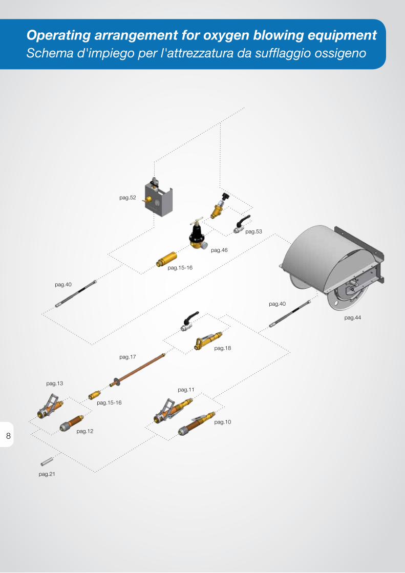
Operating arrangement for oxygen blowing equipmentSchema d'impiego per l'attrezzatura da sufflaggio ossigeno
pag.13
pag.12
pag.17
pag.11
pag.18
pag.44
pag.15-16
pag.52
pag.46
pag.53
pag.40
pag.21
pag.10
pag.15-16
pag.40

456
23
1
9
OXYGEN BLOWINGINSUFFLAGGIO OSSIGENO
• compact units attrezzature compact
• lance holders portalancia
• safety devices valvole di sicurezza
• extension tube impugnature di prolunga
• shut-off valves valvole di intercettazione
• specific applications applicazioni specifiche

10
1
NOTE / NOTA:
1) Before ordering, ensure that the external diameter of the lances in use are included within the range of the tolerances indicated
1) In fase di ordine verificare sempre che il diametro esterno delle lance utilizzate rientri nell’intervallo di tolleranza indicato
2) On request, can be supplied with coupling “A” with thread different from the table
2) A richiesta si forniscono con raccordo “A” di filettatura diversa dalla tabella
3) Only for ladle washing. Not suitable for Oxygen injection.3) Solo per lavaggio Siviere. Non indicato per insufflaggio ossigeno.
FEATURES
Used for ladle and tundish discharge opening operations.
Same characteristics as the lance holder (page 12) but with
the advantage of combining the safety valve (page 15)
and the shut off valve (page 18) in one compact unit.
For specific requirements we supply the version "without lever", which integrates the antiflashback device in the
lance holder equipment.It needs the installation of a
separate shut-off valve.
CARATTERISTICHE
Viene usata per operazioni di apertura scarico siviera e
paniera. Stesse caratteristiche del portalancia (pag. 12) con il vantaggio di riunire in un unico
attrezzo anche la valvola di sicurezza (pag.15) e la valvola
di intercettazione (pag.18).
Per esigenze specifiche può essere fornita la versione
"senza leva" che integra nel portalancia la sola valvola
di sicurezza con dispositivo antiritorno di fiamma.
Richiede l'installazione di valvola di intercettazione
separata.
C O M PA C T U N I TØ 6 m m ÷ 3 / 4 ” B S P
AT T R E Z Z AT U R AC O M PA C T
Ø 6 m m ÷ 3 / 4 ” b S P
COMPACT UNIT / ATTREZZATURA COMPACT
Lance Diameter d (external)Diametro Lancia d (esterno)
CouplingRaccordo
DimensionsDimensioni
CodeCodice
Nominal øø Nominale
Range of tolleranceIntervallo di tolleranza A(2) ø
max l
bSP mm mm(1) bSP/GAS mm mm
3/8” 17 16-17,2 3/4” 55 350 0645-270691
1/2” 21 20-21,5 3/4” 55 350 0645-270721
3/4”(3) 27 26-27,5 3/4” 60 365 0645-270771
COMPACT UNIT / ATTREZZATURA COMPACT
Lance Diameter d (external)Diametro Lancia d (esterno)
CouplingRaccordo
DimensionsDimensioni
CodeCodice
Nominal øø Nominale
Range of tolleranceIntervallo di tolleranza A(2) ø
max l
bSP mm mm(1) bSP/GAS mm mm
-- 6 4,8-6,3 3/4” 40 265 0645-270561
-- 8 6,4-8,3 3/4” 40 265 0645-270581
1/8” 10 9,1-10,2 3/4” 40 265 0645-270601
1/4” 13 12-13,7 3/4” 40 265 0645-270641
C O M PA C T U N I TATTREZZATURA COMPACT
A
l
d
A
l
d

11
1C O M PA C T U N I TATTREZZATURA COMPACT
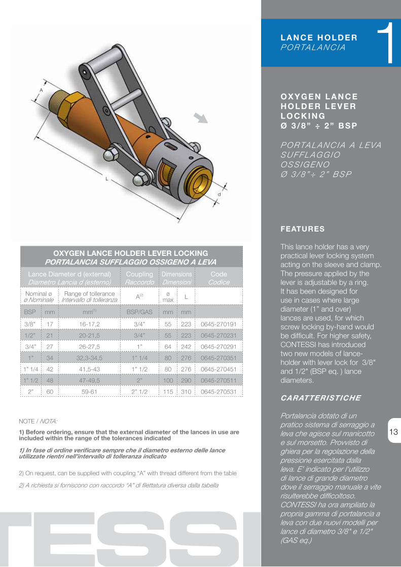
C O M PA C T U N I T L A N C E H O L D E R W I T H L E V E R L O C K I N G S Y S T E MØ 3 / 8 ” ÷ 1 / 2 ” B S P
AT T R E Z Z AT U R A C O M PA C TC O N S I S T E M A D I b L O C C A G G I O A L E VAØ 3 / 8 ” ÷ 1 / 2 ” b S P
FEATURES Used for ladle and tundish discharge opening operations.Same characteristics as the lever lance holder (page 13) but with the advantage of combining the safety valve (page 15) and the shut off valve (page 18) in one compact unit.
CARATTERISTICHE Viene usata per operazioni di apertura scarico siviera epaniera. Stesse caratteristiche del portalancia a leva (pag. 13) con il vantaggio di riunire in un unico attrezzo anche la valvola di sicurezza (pag.15) e la valvola di intercettazione (pag.18).
NOTE / NOTA:
1) Before ordering, ensure that the external diameter of the lances in use are included within the range of the tolerances indicated
1) In fase di ordine verificare sempre che il diametro esterno delle lance utilizzate rientri nell’intervallo di tolleranza indicato
2) On request, can be supplied with coupling “A” with thread different from the table
2) A richiesta si forniscono con raccordo “A” di filettatura diversa dalla tabella
COMPACT UNIT WITH LOCKING LEVERATTREZZATURA COMPACT CON LEVA DI BLOCCAGGIO
Lance Diameter d (external)Diametro Lancia d (esterno)
CouplingRaccordo
DimensionsDimensioni
CodeCodice
Nominal øø Nominale
Range of tolleranceIntervallo di tolleranza A(2) ø
max l
bSP mm mm(1) bSP/GAS mm mm
3/8” 17 16-17,2 3/4” 55 350 0645-270851
1/2” 21 20-21,5 3/4” 55 350 0645-270871
A
l
d

12
1
NOTE / NOTA:
1) Before ordering, ensure that the external diameter of the lances in use are included within the range of the tolerances indicated
1) In fase di ordine verificare sempre che il diametro esterno delle lance utilizzate rientri nell’intervallo di tolleranza indicato
2) On request, can be supplied with coupling “A” with thread different from the table
2) A richiesta si forniscono con raccordo “A” di filettatura diversa dalla tabella
FEATURES
All materials in contact with Oxygen are bronze or brass.
Seals manufactured out of self-extinguishing abrasion-
resistant rubber. This ensures the safety of the inserted lance
by the combination of clamp and rubber sleeve. quick lance
locking by rotating nut.Suitable for operations of ladle/tundish opening and unloading.
CARATTERISTICHE
Materiale a contatto con l’ossigeno in bronzo e ottone.
Guarnizioni in gomma autoestinguente, resistenteall’abrasione ed all’ozono.
Il bloccaggio dellalancia viene assicurato da
una pinza a settori elastici in abbinamento al manicotto di
gomma.Serraggio rapido a mezzo dado girevole.
Viene usata per operazionidi apertura scarico
siviera e paniera.
O X Y G E NL A N C E H O L D E R
Ø 6 m m ÷ 3 / 4 ” B S P
P O R TA L A N C I AS U F F L A G G I O
O S S I G E N OØ 6 m m ÷ 3 / 4 ” B S P
L A N C E H O L D E RP O R TA L A N C I A
OXYGEN LANCE HOLDERPORTALANCIA SUFFLAGGIO OSSIGENO
Lance Diameter d (external)Diametro Lancia d (esterno)
CouplingRaccordo
DimensionsDimensioni
CodeCodice
Nominal øø Nominale
Range of tolleranceIntervallo di tolleranza A(2) ø
max l
bSP mm mm(1) bSP/GAS mm mm
-- 6 4,8-6,3 3/4” 40 135 0645-270061
-- 8 6,4-8,3 3/4” 40 135 0645-270081
1/8” 10 9,1-10,2 3/4” 40 135 0645-270101
1/4” 13 12-13,7 3/4” 40 135 0645-270141
3/8” 17 16-17,2 3/4” 55 175 0645-270171
1/2” 21 20-21,5 3/4” 55 175 0645-270211
3/4” 27 26-27,3 1” 60 190 0645-270271
A
d
l
13
FEATURES This lance holder has a very practical lever locking system acting on the sleeve and clamp.The pressure applied by the lever is adjustable by a ring.It has been designed foruse in cases where large diameter (1” and over)lances are used, for which screw locking by-hand wouldbe difficult. For higher safety, CONTESSI has introduced two new models of lance-holder with lever lock for 3/8" and 1/2" (bSP eq. ) lance diameters.
CARATTERISTICHE Portalancia dotato di un pratico sistema di serraggio a leva che agisce sul manicotto e sul morsetto. Provvisto di ghiera per la regolazione della pressione esercitata dalla leva. E’ indicato per l'utilizzo di lance di grande diametro dove il serraggio manuale a vite risulterebbe difficoltoso.CONTESSI ha ora ampliato la propria gamma di portalancia a leva con due nuovi modelli per lance di diametro 3/8" e 1/2" (GAS eq.)
O X Y G E N L A N C E H O L D E R L E V E RL O C K I N GØ 3 / 8 ” ÷ 2 ” B S P
P O R TA L A N C I A A L E VAS U F F L A G G I OO S S I G E N OØ 3 / 8 ” ÷ 2 ” b S P
OXYGEN LANCE HOLDER LEVER LOCKINGPORTALANCIA SUFFLAGGIO OSSIGENO A LEVA
Lance Diameter d (external)Diametro Lancia d (esterno)
CouplingRaccordo
DimensionsDimensioni
CodeCodice
Nominal øø Nominale
Range of tolleranceIntervallo di tolleranza A(2) ø
max l
bSP mm mm(1) bSP/GAS mm mm
3/8” 17 16-17,2 3/4” 55 223 0645-270191
1/2” 21 20-21,5 3/4” 55 223 0645-270231
3/4” 27 26-27,5 1” 64 242 0645-270291
1” 34 32,3-34,5 1” 1/4 80 276 0645-270351
1” 1/4 42 41,5-43 1” 1/2 80 276 0645-270451
1” 1/2 48 47-49,5 2” 100 290 0645-270511
2” 60 59-61 2” 1/2 115 310 0645-270531
1L A N C E H O L D E RP O R TA L A N C I A
NOTE / NOTA:
1) Before ordering, ensure that the external diameter of the lances in use are included within the range of the tolerances indicated
1) In fase di ordine verificare sempre che il diametro esterno delle lance utilizzate rientri nell’intervallo di tolleranza indicato
2) On request, can be supplied with coupling “A” with thread different from the table
2) A richiesta si forniscono con raccordo “A” di filettatura diversa dalla tabella
A
l
d

14
1 L A N C E H O L D E RP O R TA L A N C I A
O X Y G E N L A N C EH O L D E R
Ø 1 ” ÷ 2 ” B S P, W I T H H O O K W R E N C H
L O C K - N U T
P O R TA L A N C I A S U F F L A G G I O
O S S I G E N OØ 1 ” ÷ 2 ” b S P,
C O N D A D OD I b L O C C A G G I O
P E R C h I AV EA S E T T O R E
FEATURES
All materials in contact with Oxygen are bronze or brass.
Seals manufactured out of self-extinguishing abrasion-resistant
rubber.This ensures thesafety of the inserted lance by the
combination of clamp and rubber sleeve. quick locking
nut with tightening wrench.Suitable for oxygen blowing
operations, rigged on manipulators.
CARATTERISTICHE
Materiale a contatto con l’ossigeno in bronzo e ottone.
Guarnizioni in gomma autoestinguente, resistente all’abrasione ed all’ozono.
Il bloccaggio della lancia viene assicurato da una pinza a
settori elastici in abbinamento al manicotto di gomma.
Serraggio rapido con dado girevole e chiavetta di
serraggio rinforzata. Viene usata per operazioni di
insufflaggio ossigeno mediante manipolatore. É munito di fori
per chiave di serraggio.
OXYGEN LANCE HOLDER WITH HOOK WRENCH LOCK-NUTPORTALANCIA SUFFLAGGIO OSSIGENO CON DADO DI
BLOCCAGGIO PER CHIAVE A SETTORE
Lance Diameter d (external)Diametro Lancia d (esterno)
CouplingRaccordo
DimensionsDimensioni
CodeCodice
Nominal øø Nominale
Range of tolleranceIntervallo di tolleranza A(2) ø
max l
bSP mm mm(1) bSP/GAS mm mm
1" 33 32,3-34,5 1"1/4 80 215 0645-270321
1"1/4 42 42-43 1"1/2 80 215 0645-270411
1"1/2 48 47-49,5 2" 100 245 0645-270461
2" 60 59-61 2"1/2 115 290 0645-270501
Spare tightening wrench / Chiavetta di serraggio di ricambio 0498-036872
NOTE / NOTA:
1) Before ordering, ensure that the external diameter of the lances in use are included within the range of the tolerances indicated
1) In fase di ordine verificare sempre che il diametro esterno delle lance utilizzate rientri nell’intervallo di tolleranza indicato
2) On request, can be supplied with coupling “A” with thread different from the table
2) A richiesta si forniscono con raccordo “A” di filettatura diversa dalla tabella
A
l
d

15
1S A F E T Y VA LV E SVALVOLE DI SICUREZZA
FEATURES Fitted with a non-return valve and a thermal device to shut off oxygen in case of backfire or slag return. If the thermal device operates the unit must be dismantled for repair. Inlet connection: bSP thread male.Outlet connection: bSP thread female
CARATTERISTICHE La valvola munita di antiritorno di gas, è corredata di un dispositivo termico che interrompe il passaggio dell’ossigeno in seguito ad eventuale surriscaldamento dell’attrezzatura.Il funzionamento del dispositivo termico provoca il blocco della valvola che dovrà essere smontata e revisionata.Raccordo di entrata con filettatura GAS maschioRaccordo di uscita con filettatura GAS femmina
5248
CouplingRaccordo
DimensionsDimensioni
CodeCodice
A ø max l
bSP/GAS mm mm
3/4” 36 85 0646-331652
F O R B L O W I N G E Q U I P M E N T
P E R AT T R E Z Z AT U R A I N S U F F L A G G I O
S E R I E S 5 2 4 8 : no flow of oxygenif lance fitted incorretlySERIE 5248: con blocco passaggio ossigeno per errato inserimento del tubo
S E R I E S 5 2 4 9 : for medium flow rateSERIE 5249: per medie portate
5249
CouplingRaccordo
DimensionsDimensioni
CodeCodice
A ø max l
bSP/GAS mm mm
1/2” 36 90 0646-331621
3/4” 36 90 0646-331601
A
l A
A
lA

16
1 S A F E T Y VA LV E SVALVOLE DI SICUREZZA
SERIES 5282: large flow rate with minimum pressure lossSERIE 5282: di grande erogazione e minime perdite di carico
FEATURES
Fitted with a non-return valve and a thermal device to shut
off oxygen in case of backfire or slag return. If the thermal
device operates the unit must be dismantled for repair.
Inlet connection:bSP thread male
Outlet connection:bSP thread female
CARATTERISTICHE
La valvola munita di antiritorno di gas, è corredata di un
dispositivo termico che interrompe il passaggio
dell’ossigeno in seguito ad eventuale surriscaldamento
dell’attrezzatura.Il funzionamento del dispositivo
termico provoca il blocco della valvola che dovrà essere
smontata e revisionata.Raccordo di entrata con filettatura GAS maschioRaccordo di uscita con filettatura GAS femmina
F O R B L O W I N G E Q U I P M E N T
P E R AT T R E Z Z AT U R A I N S U F F L A G G I O
CHECK VALVE PN64
This valve block reverse flow and preserve the system from water-hammer. Manufactured out from stainless steel bars. Inlet/Outlet connection bSP
thread Female
VALVOLA DI RITEGNO PN64
Và utilizzata per evitare i ritorni di fluido assicurandone il
passaggio nella sola direzione del flusso e per proteggere l’impianto in caso di colpo
d’ariete. Costruita da barra di Acciaio Inox. Raccordi di
Entrata e Uscita con filettatura GAS Femmina
Check valve PN64Valvola di ritegno PN64
5 2 8 2
ModelModello
CouplingRaccordo
DimensionsDimensioni
CodeCodice
A ø max l
bSP/GAS mm mm
h 2” 120 195 0646-331791
S E R I E I N O X 3 1 6
ModelModello
CouplingRaccordo
DimensionsDimensioni
CodeCodice
A ø max l
bSP/GAS mm mm
D 3/4” 50 80 0625-330041
E 1” 50 85 0625-330051
F 1”1/4 60 90 0625-330061
G 1”1/2 70 95 0625-330071
h 2” 80 110 0625-330081
A
lA
A
l A
A
lA
5 2 8 2
ModelModello
CouplingRaccordo
DimensionsDimensioni
CodeCodice
A ø max l
bSP/GAS mm mm
D 3/4” 40 147 0646-331751
E 1” 48 177 0646-331761
F 1”1/4 55 197 0646-331771
G 1”1/2 65 215 0646-331781

17
1STRAIGHT / DIRITTA
Coupling Raccordo
DimensionsDimensioni
Copper codeCodice rame
Inox codeCodice Inox
A (bSP/GAS) D l
3/4” 32 500 0610-220061 0610-220201
1” 38 1000 0610-220071 0610-220211
1”1/4 38 1000 0610-220081 0610-220221
1”1/2 38 1000 0610-220091 0610-220231
2” 45 1000 0610-220101 0610-220241
EXTENSION TUBESIMPUGNATUREDI PROLUNGA
FEATURES Extension tube for installing between safety valve and flexible hose. Manufactured with copper or stainless steel pipe.Inlet connection: bSP thread maleOutlet connection: bSP thread female
CARATTERISTICHE Elemento di raccordo tra il tubo flessibile e la valvola di sicurezza. Viene costruita in tubo di rame o in acciaio inox.Raccordo di entrata con filettatura GAS maschioRaccordo di uscita con filettatura GAS femmina
90° BEND / PIEGATA 90°
Coupling Raccordo
DimensionsDimensioni
Copper codeCodice rame
Inox codeCodice Inox
A (bSP/GAS) D lO lv
3/4” 32 200 400 0610-220111 0610-220251
1” 38 200 400 0610-220121 0610-220261
1”1/4 38 200 400 0610-220131 0610-220271
1”1/2 38 200 400 0610-220141 0610-220281
2” 45 400 500 0610-220151 0610-220291
F O R B L O W I N G E Q U I P M E N T
P E R AT T R E Z Z AT U R A S U F F L A G G I O
A
l
A
D
A
lv
D
A
lO

18
* Provided with male adaptor for inlet connection Fornita con adattatore maschio sul raccordo di entrata
FEATURES
valve offering maximum operator safety.
The flow of oxygen is regulated by the gradual pressure
exercised by the operator on the lever. Release of the lever
interrupts the oxygen flow.Inlet connection:bSP thread male
Outlet connection:bSP thread female
CARATTERISTICHE
Valvola di massima sicurezza.Il flusso dell’ossigeno è regolato
dall’azione graduale che l’operatore esercita sulla leva.
Rilasciando la leva si interrompe il flusso dell’ossigeno.
Raccordo di entrata con filettatura GAS maschioRaccordo di uscita con filettatura GAS femmina
FEATURES
brass body, stainless steel ball, teflon seals. Suitable for the use
with Oxygen.
CARATTERISTICHE
Corpo in ottone, sfera in inox, guarnizioni in teflon. Idonea al
passaggio di ossigeno.
S H U T O F F VA LV E FA I L S A F E C L O S I N G
S E R I E S 5 2 4 6
VA LV O L A I N T E R C E T TA Z I O N E
S H U T O F F B A L L VA LV E
VALVOLA INTERCETTAZIONE
A SFERA
VIAS MxF
ModelModello
*Coupling Raccordo
CodeCodice
A(bSP/GAS)
vIAS 3/4” MxF 3/4” 0628-341401
vIAS 1” MxF 1” 0628-341411
vIAS 1”1/4 MxF 1”1/4 0628-341421
vIAS 1”1/2 MxF 1”1/2 0628-341431
1 SHUT OFF VALVESVALVOLE INTERCETTAZIONE
5246
ModelModello
CouplingRaccordo
DimensionsDimensioni
CodeCodice
A(bSP/GAS)
l mm
Standard 3/4" 260 0628-341011
Protected leverA leva protetta 3/4" 260 0628-341021
A
l
A
A
A
A
l
A

19
1S P E C I F I CA P P L I C AT I O N SAPPLICAZIONI SPECIFIChE
FEATURES Utilized in the injection of oxygen on AOD converter.Cooling with argon. Standard construction includes copper lance with stainless steel outside pipe for cooling, carbon steel T-joint, 1” bSP connection for oxygen and argon, on request supplied with OT58 brass quick-action couplings on the connections.length and pipe diameter on request.
CARATTERISTICHE Utilizzate per insufflaggio di ossigeno nei convertitori.Raffreddamento a mezzo argon. L’esecuzione standard prevede lancia in rame con cannula di raffreddamento acciaio inox, giunto a T in acciaio al carbonio, attacco filettato 1” GAS per ossigeno e argon con possibilità di fornitura comprensiva di innesti rapidi in OT58. Lunghezza e diametri a richiesta.
T U Y È R E S F O R “ A O D ” C O N V E RT E R S
T U b I E R E P E R C O N V E R T I T O R I “ A O D ”
AOD Converter
* Provided with male adaptor for inlet connection Fornita con adattatore maschio sul raccordo di entrata
l
l

20
MOLTEN METAL EXHAUSTERASPIRATORE METALLO FUSO
CouplingRaccordo
LengthLunghezza
CodeCodice
A l
bSP / GAS mm
3/4” On request / A richiesta 0628-270010
1 S P E C I F I CA P P L I C AT I O N S
APPLICAZIONI SPECIFIChE
M O LT E N M E TA LE X H A U S T E R
A S P I R AT O R EM E TA L L O F U S O
FEATURES
venturi suction device at compressed air, for analysing
equipment, for an easy take-up of steel samples.
CARATTERISTICHE
Dispositivo di aspirazione.Venturi a funzionamento pneumatico. Consente il
prelievo rapido di campioni di metallo fuso per analisi.
FEATURES
Disposable cartdriges for direct sampling, fast and safe. Their
special design reduces lab preparation time and provides
representative samples of molten metal ready for
chemical analysis after a simple surface cleaning.
CARATTERISTICHE
Cartucce monouso per campionamento diretto, rapido
e sicuro. Lo speciale disegno riduce i tempi di preparazione
in laboratorio, fornendo un campione rappresentativo del
bagno liquido subito pronto per l'analisi chimica dopo una semplice pulitura superficiale.
D I S P O S A B L E C A RT D R I G E S
CARTUCCE MONOUSO
DISPOSABLE CARTDRIGESCARTUCCE MONOUSO
ØInsertion holeInserimento
LengthLunghezza
CodeCodice
d l
mm mm
38 250 0635-211350
A
l
l
d

21
1T H E R M A L L A N C E
L A N C I A T E R M I C A
S P E C I F I CA P P L I C AT I O N SAPPLICAZIONI SPECIFIChE
FEATURES It is used in steelmaking for quick opening of the Tap holes of casting furnaces, for torpedo-ladle-wagons descaling, for converter maintenace operations, for slag scrap removal, etc. Suitable for cutting, drilling and demolishing big pieces of solid materials of various nature for instance: carbon steels, cast irons and ferrous alloys including stainless steels, aluminium and light alIoys, concrete, granites, marbles, natural stones and refractories. The process allows easy execution of work, money saving, swift execution.
CARATTERISTICHEViene usata in siderurgia per aprire rapidamente le bocche di colata degli altiforni, per disincrostare carri siluro e convertitori, per eliminare scorie, ecc. Adatta per tagliare, forare, demolire grandi masse di materiale solido di diversa natura quali acciaio, acciaio inossidabile, ghisa, alluminio, bronzo, calcestruzzo, marmi, graniti, roccia e refrattari. Il procedimento consente facilità di lavoro, economicità di costi, rapidità di esecuzione.
LIGHTING DEVICEFOR THERMAL LANCES
ACCENDITORE PER LANCE TERMIChE
FEATURES The lighting device allows the ignition of thermal lances and oxygen blowing pipes without presenting risks to the operator.The combustion of the lighting device make incandescent the end of the lance into which it has been inserted. The lance is made operational by the subsequent passage of the oxygen.
CARATTERISTICHE Consente l’innesco di lance termiche e cannette per l’ossigeno senza rischi per l’operatore.La combustione del dispositivo rende incandescente la punta della lancia sulla quale è innestato.La successiva apertura del flusso dell'ossigeno permette l’operatività della lancia.
THERMAL LANCE / LANCIA TERMICA
Diameter dDiametro d
LengthLunghezza
CodeCodice
With threaded coupling
Con manicotto filettato
mm mm
6 1180 0616-210945
8 2000 0616-210951
10 2000 0616-210961
17 - 3/8” (A) 3000 0616-210971 0616-210981
21 - 1/2” (A) 3000 0616-211001 0616-211011
LIGHTING DEVICEACCENDITORE
DiameterDiametro
CodeCodice
1/8” 0635-211140
1/4” - 3/8” 0635-211150
1/2” 0635-211160
3/4” 0635-211170
d
dA

22
Operating arrangement for oxygen cutting equipmentSchema d'impiego per l'attrezzatura ossitaglio
pag.26
pag.33
pag.45
pag.58
pag.40
pag.52
pag.46
pag.53
pag.58
pag.58
pag.42
pag.53
pag.46
pag.40
pag.52

23
O X Y G E N C U T T I N GO S S I TA G L I O
• torches for cutting machines cannelli per macchine ossitaglio
• torches for break-up works cannelli per demolizione
• quick intervention torches cannelli per pronto intervento
• scarfing torches cannelli per scriccatura
• cutting torches for alloyed steel cannelli per taglio acciai legati
• accessories for oxy-cutting accessori per ossitaglio

24
FEATURES
Control valves with stainless steel pin and teflon packings.
Independent oxy-cutting supply and high heating capacity.
Oxy-propane and oxy-methane (Natural Gas) operation.
Sturdy construction, suited for heavy duty in steel mills.
Custom length on request.
CARATTERISTICHE
Rubinetti con spilloin acciaio inossidabile e guarnizioni in teflon.
Alimentazione dell’ossigeno taglio indipendente ed
elevata potenza di riscaldo. Funzionamento ossipropanico
e ossimetanico. Costruzione robusta particolarmente
adatta per il gravoso lavoro in acciaieria. A richiesta lunghezze
fuori standard.
O X Y G E N C U T T I N G T O R C H E S F O R
M A C H I N E S
C A N N E L L IP E R M A C C h I N E
O S S I TA G L I O
ITI/S
For cutting up to 900 mm, water cooled on requestPer taglio spessori fino a mm 900, disponibile anche in versione
con raffreddamento ad acqua
Torch seriesCannello serie
Outting thicknessSpessore
taglio
Auto-mixing nozzlesUgelli automiscelanti
Standard Water cooled mm Type/Tipo Code / Codice
ITI/S*0604-150429
ITI/S W.C.*0604-150369
200÷400 S.400 0407-026312
400÷700 S.700 0407-026322
700÷900 S.900 0407-026332
Locking nut for nozzle / Dado bloccaggio ugello 0418-038301
T O R C H E SC A N N E L L I
ISI/09For cutting up to 400 mm / Per taglio spessori fino a mm 400
Torch seriesCannello
serie
LPG / methane(Natural Gas)
GPL / metano
AcetyleneAcetilene
ISI/0
9 *
0604
-150
539
Cutting thicknessSpessore
taglio
Auto-mixingnozzlesUgelli
automiscelanti
Cutting thicknessSpessore
taglio
Auto-mixingnozzlesUgelli
automiscelanti
mm TypeTipo
CodeCodice mm Type
TipoCode
Codice
20÷40 RFP.1 0406-020014 3÷20 RFA.1 0405-019914
40÷60 RFP.2 0406-020024 20÷65 RFA.2 0405-019924
60÷80 RFP.3 0406-020034 65÷100 RFA.3 0405-019934
80÷100 RFP.4 0406-020044 100÷150 RFA.4 0405-019944
100÷150 RFP.5 0406-020054 150÷200 RFA.5 0405-019954
150÷200 RFP.6 0406-020064 200÷300 RFA.6 0405-019964
200÷300 RFP.7 0406-020074
280÷330 RFP.8 0406-020084
330÷370 RFP.9 0406-020094
370÷400 RFP.10 0406-020104
Locking nut for nozzle / Dado bloccaggio ugello 0406-022102
MT/GE
For continuous casting machines, water cooledPer macchine colata continua, con raffreddamento ad acqua
Torch seriesCannello
serie
OuttingthicknessSpessore
taglio
Auto-mixing nozzlesUgelli automiscelanti
MT/GE* 0604-163706
mm Type/Tipo Code / Codice
50÷300 MTT/GE.6 0407-024961
100÷500 MTT/GE.7 0407-024971
150÷750 MTT/GE.8 0407-024951
* Standard length 500mm / Lunghezza standard 500mm External ø 32 mm / ø Esterno 32mm
* Standard length 500mm / Lunghezza standard 500mm External ø 45 mm / ø Esterno 45mm
* Standard length 1000mm / Lunghezza standard 1000mm External ø 50 mm / ø Esterno 50mm

25
O X Y G E N C U T T I N G T O R C H E S F O R M A C H I N E S
C A N N E L L IP E R M A C C h I N E O S S I TA G L I O
RELATED ACCESSORIES
Pilot Flame Torch.To be rigged on MT/GE series torches for continuous casting oxycutting machines; brass body, valves and connections; pipe and nozzle made in stainless steel. Working with combustible gas and aspirated air.
ACCESSORI CORRELATI
Cannello per Fiamma Pilota.Per il montaggio su cannelli serie MT/GE per macchine ossitaglio per colata continua;corpo, valvole e raccorderia in ottone. Condotta, punta e deflettore in acciaio inox.Funzionamento con gas combustibile e aria aspirata.
T O R C H E SC A N N E L L I
PILOT FLAME TORCHCANNELLO FIAMMA PILOTA
Length / Lunghezza Code / Codice
1070mm 0621-370914
* Standard length 1000mm / Lunghezza standard 1000mm External ø 50 mm / ø Esterno 50mm
MTT/1251
For cutting up to 1200 mm, water cooledPer taglio spessori fino a 1200 mm, con raffreddamento ad acqua
Torch seriesCannello
serie
OuttingthicknessSpessore
taglio
Auto-mixing nozzlesUgelli automiscelanti
MTT/1251* 0604-164505
mm Type/Tipo Code / Codice
600÷800 PPCS. 9 0407-012091
800÷1000 PPCS.10 0407-012101
1000÷1200 PPCS.11 0407-012121
Locking nut for nozzle/Dado bloccaggio ugello 0418-012111
* Standard length 1000mm / Lunghezza standard 1000mm External ø 80 mm / ø Esterno 80mm
ERC
For cutting up to 1500 mm, water cooledPer taglio spessori fino a mm 1500, con raffreddamento ad acqua
Torch seriesCannello
serie
OuttingthicknessSpessore
taglio
Auto-mixing nozzlesUgelli automiscelanti
*ERC0604-150406
mm Type/Tipo Code / Codice
600÷900 lvS.16 0407-026101
900÷1200 lvS.18 0407-026111
1200÷1500 lvS.20 0407-026121
Locking nut for nozzle/Dado bloccaggio ugello 0418-026851

26
FEATURES
Sturdy construction, suited for heavy duty. Control valves with
stainless steel pin and teflon packings. Different options for the nozzle-holder head angle.
Customized lengths on request. Oxy-propane and oxy-methane
operation.
On request provided with iron powder device for cutting of
alloyed steel.
CARATTERISTICHE
Particolarmente robusti, adatti per lavori gravosi. Rubinetti con
spillo in acciaio inox.A richiesta possono essere
forniti di lunghezze fuori standard e con diverse angolazioni della testa
portaugelli. Funzionamento ossipropanico e ossimetanico.
A richiesta si forniscono le versioni INOX con dispositivo di adduzione polvere di ferro per il
taglio di acciai legati.
O X Y G E N C U T T I N G T O R C H E S
F O R S L A G / S C R A PB R E A K U P W O R K
C A N N E L L I O S S I TA G L I O
P E R D E M O L I Z I O N E
T O R C H E SC A N N E L L I
GS/TT
Torch seriesCannello serie
Cutting thicknessSpessore taglio
NozzlesUgelli
GS/TT0603-140909*
mm Type / Tipo Code / Codice
400÷500 MTT.3 0406-020591
500÷600 MTT.4 0406-020601
600÷700 MTT.5 0406-020611
Locking nut for nozzle / Dado bloccaggio 0418-022842
* Standard length 1130 mm. Other length on request* Lunghezza standard 1130 mm. Su richiesta fornibile in altre lunghezze
* Standard length 1800 mm. Other length on request* Lunghezza standard 1800 mm. Su richiesta fornibile in altre lunghezze
Sturdy construction, nozzle-mixing blowpipe (safer against flashbacks)with knob gas flow control. Distinct inlet connections for cutting and heating oxygen. It can be used with fork-joint connection on O2 inlet (lower performances). Suitable for very high thickness cuts.
Cannello per ugelli automiscelanti.Valvole di regolazione a volantino. Raccordi di entrata separati per ossigeno di taglio e riscaldo. Possibilità di utilizzo con forcella per collegamento raccordato dell'ossigeno (prestazioni inferiori). Indicato per spessori elevati in alternativa alla lancia termica.Di costruzione robusta, è adatto per lavori di demolizione, siderurgia, fonderia, taglio materozze, officine meccaniche, e in tutti gli impieghi dove è richiesta elevata potenza di taglio.
Nozzle-mixing blowpipe (safer against flashbacks) with knob gas-flow control. head angle 180°. Distinct inlet connections for cutting and heating oxygen. It can be used with fork-joint connection on O2 inlet (lower performances). Suitable for heavy demolition, steelmaking, casting, sprue cutting, scrap cutting, cutting of very thick steel pieces.
Cannello con testa a 180° per ugelli automiscelanti. Valvole di regolazione a volantino. Raccordi di entrata separati per ossigeno di taglio e riscaldo. Possibilità di utilizzo con forcella per collegamento raccordato dell'ossigeno con l'impiego di un solo tubo flessibile (prestazioni inferiori). Di costruzione robusta è adatto per attività di demolizione pesante, siderurgia, fonderia, taglio materozze, taglio rottami, taglio di spessori molto elevati.
GRM
Torch seriesCannello serie
Cutting thicknessSpessore taglio Nozzles / Ugelli
GRM 0603-140759*
mm Type / Tipo Code / Codice
600÷800 RM. 8 0406-012203
800÷1000 RM.10 0406-012213
Locking nut for nozzle / Dado bloccaggio 0418-038261

27
O X Y G E N C U T T I N G T O R C H E SF O R S L A G / S C R A PB R E A K U P W O R K
C A N N E L L I O S S I TA G L I OP E R D E M O L I Z I O N E
FEATURES Sturdy construction, suited for heavy duty. Control valves with stainless steel pin and teflon packings. Different options for the nozzle-holder head angle. Customized lengths on request. Oxy-propane and oxy-methane operation.
CARATTERISTICHE Particolarmente robusti, adatti per lavori gravosi. Rubinetti con spillo in acciaio inox.A richiesta possono essere forniti di lunghezze fuori standard e con diverse angolazioni della testa portaugelli. Funzionamento ossipropanico e ossimetanico.
T O R C H E SC A N N E L L I
* Standard length 1200 mm. Other length on request* Lunghezza standard 1200 mm. Su richiesta fornibile in altre lunghezze
Nozzle-mixing blowpipe (safer against flashbacks), with lever control.Suitable for all uses of maintenance and emergency services: break up work, steelmaking, foundry, cutting sprue, mechanical workshop.Suitable for maintenance works and special applications. It can operate with acetylene or propane gas by merely replacing the nozzle.
Cannello versatile per ugelli automiscelanti (più sicuro contro i ritorni di fiamma) con comando a leva.Adatto per tutti gli impieghi di manutenzione e pronto intervento: lavori di demolizione, siderurgia, fonderia, taglio materozze, officine meccaniche.Adatto per impieghi di manutenzione e lavorazioni particolari. Con la semplice sostituzione delle punte può funzionare con gas acetilene e propano.
MRH/LV/TT
Torch seriesCannello serie
LPG / methane (Natural Gas)GPL / metano
AcetyleneAcetilene
MRh/lv/TT*Cutting
thicknessSpessore
taglioNozzles / Ugelli
CuttingthicknessSpessore
taglioNozzles / Ugelli
Nozzle head angleAngol.testa
Code
Codicemm
Type
Tipo
Code
Codicemm
Type
Tipo
Code
Codice
90°
135°
180°
0603-140429
0603-140419
0603-140409
20÷40 RFP.1 0406-020014 3÷20 RFA.1 0405-019914
40÷60 RFP.2 0406-020024 20÷65 RFA.2 0405-019924
60÷80 RFP.3 0406-020034 65÷100 RFA.3 0405-019934
80÷100 RFP.4 0406-020044 100÷150 RFA.4 0405-019944
100÷150 RFP.5 0406-020054 150÷200 RFA.5 0405-019954
150÷200 RFP.6 0406-020064 200÷300 RFA.6 0405-019964
200÷300 RFP.7 0406-020074
280÷330 RFP.8 0406-020084
330÷370 RFP.9 0406-020094
370÷400 RFP.10 0406-020104
Locking nut for nozzle / Dado bloccaggio 0418-022102

28FEATURES
Nozzle-mixing cutting torches.
Oxy-propane, oxy-methane (Natural Gas) and oxy-
acetylene operation.
CARATTERISTICHE
Cannelli per ugelli automiscelanti.Funzionamento ossipropanico, ossimetanico e ossiacetilenico.
Q U I C K I N T E RV E N T I O N
O X Y G E N - C U T T I N G T O R C H
C A N N E L L O TA G L I O P R O N T O I N T E R V E N T O
T O R C H E SC A N N E L L I
Nozzle-mixing blowpipe (safer against flashbacks), with lever control. Available in different length up to 2000 mm.Suitable for all uses of maintenance and emergency services: break up work, steelmaking, foundry, cutting sprue, mechanical workshop.
Cannello versatile a miscelazione in punta (maggiore sicurezza contro i ritorni di fiamma) con comando a leva, disponibile in varie lunghezze fino a 2000 mm.Adatto per tutti gli impieghi di manutenzione e pronto intervento: lavori di demolizione, siderurgia, fonderia, taglio materozze, officine meccaniche.
* Standard length 500 mm. Other lengths available on request* Lunghezza standard 500 mm. Su richiesta può essere fornito in altre lunghezze
DM/89 - DM/99
Torch seriesCannello serie
LPG / methane (Natural Gas)GPL/ metano
AcetyleneAcetilene
SERIE DM*Cutting
thicknessSpessore
taglioNozzles / Ugelli
CuttingthicknessSpessore
taglioNozzles / Ugelli
Nozzle head angleAngol. testa
Code
Codice
Code
Codicemm
Type
Tipo
Code
Codicemm
Type
Tipo
Code
Codice
90°
135°
180°
DM/89
0603-141039
0603-141049
0603-141059
DM/99
0603-141189
0603-141179
0603-141199
20÷40 RFP.1 0406-020014 3÷20 RFA.1 0405-019914
40÷60 RFP.2 0406-020024 20÷65 RFA.2 0405-019924
60÷80 RFP.3 0406-020034 65÷100 RFA.3 0405-019934
80÷100 RFP.4 0406-020044 100÷150 RFA.4 0405-019944
100÷150 RFP.5 0406-020054 150÷200 RFA.5 0405-019954
150÷200 RFP.6 0406-020064 200÷300 RFA.6 0405-019964
200÷300 RFP.7 0406-020074
280÷330 RFP.8 0406-020084
Locking nut for nozzle / Dado bloccaggio 0418-022102
DM/89
DM/99

29
Q U I C K I N T E RV E N T I O N O X Y G E N - C U T T I N G T O R C H
C A N N E L L O TA G L I O P R O N T O I N T E R V E N T O
FEATURES Nozzle-mixing cutting torches.Oxy-propane, oxy-methane (Natural Gas) and oxy-acetylene operation.
CARATTERISTICHE Cannelli per ugelli automiscelanti.Funzionamento ossipropanico, ossimetanico e ossiacetilenico.
T O R C H E SC A N N E L L I
LM
Torch seriesCannello serie
Cutting thicknessSpessore taglio Nozzles / Ugelli
lM * 0603-140259
mm Type /Tipo Code / Codice
50÷300 MTT/GE.6 0407-024961
100÷500 MTT/GE.7 0407-024971
150÷750 MTT/GE.8 0407-024951
* length on request (up to 4000 mm )* Lunghezza a richiesta ( max 4000 mm )
To be used for emergency operations on continuous cutting machines. Nozzle head angle 90° (180° on request).Minimum length 1800 mm. Available with stand skid.
Utilizzato per servizi di pronto intervento su macchina di colata continuatesta a 90° (180° a richiesta).Lunghezza minima mm 1800. A richiesta con pattino di appoggio

30
FEATURES
For removal of defects on blooms, slabs and billets.heavy-duty construction
manufactured out of heat/wear-resistant stainless steel
and bronze. Oxy-propane and oxy-methane operation.
Oxygen jet for scarfing, with quick-action lever opening.
CARATTERISTICHE
Per eliminare i difetti su blumi, bramme e billette.
Costruzione robusta con materiali in acciaio inox e bronzo
resistenti al calore ed all’usura.Funzionamento ossipropanico
e ossimetanico.Getto ossigeno per scriccare,
con apertura rapida a leva.
C O M B I N E D S C A R F I N G T O R C H
F O R H I G H T H I C K N E S S C U T S
C A N N E L L O C O M b I N AT O P E R
TA G L I O S P E S S O R I E L E VAT I
E S C R I C C AT U R A
T O R C H E SC A N N E L L I
Premixed torch, combined for scarfing and cutting of high thickness material.
Cannello a miscelazione preventiva, combinato per scriccatura e taglio di spessori elevati.
MRH/LV/1
Torch seriesCannello serie
Cutting thicknessSpessore
taglio
Internal nozzlesUgelli interni
External nozzles( locking nut included )
Ugelli esterni( incluso dado di bloccaggio )
MRh/lv/10602-140125*
mm Type Tipo Code / Codice Type
Tipo Code / Codice
200÷300 GSP.1 0404-016511 GS 0402-016561
300÷400 GSP.2 0404-016521 GS 0402-016561
400÷500 GSP.3 0404-016531 GS 0402-016561
500÷600 GSP.4 0404-016541 GS 0402-016561
600÷700 GSP.5 0404-016551 GS 0402-016561
* Standard length 1200 mm. Other lengths available on request* Lunghezza standard 1200 mm. Su richiesta può essere fornito in altre lunghezze

31
S C A R F I N G T O R C H
C A N N E L L O S C R I C C AT O R E
R E L AT E D C O N S U M A B L E
M AT E R I A L I D I C O N S U M O C O R R E L AT I
T O R C H E SC A N N E L L I
SC/OX
Torch seriesCannello serie
Nozzles ( locking nut included )Ugelli ( incluso dado di bloccaggio )
Width of passesSolco scanalato
SC/Ox 0602-140596*
Type / Tipo Code / Codice mm
F.16 0407-024251 85
* Standard length 1500 mm. Other lengths available on request* Lunghezza standard 1500 mm. Su richiesta può essere fornito in altre lunghezze
Nozzle-mixing scarfing torch, with lever control. equipped with automatic striking rod advance.
Cannello per scriccatura a miscelazione in punta (che garantisce maggiore sicurezza contro i ritorni di fiamma). Con comando a leva e sistema di avanzamento automatico della bacchetta d'innesco.
RODS FOR SCARFING TORCHESBACCHETTE PER INNESCO CANNELLI SCRICCATORI
CompositionMateriale
LengthLunghezza
Package contentContenuto confezione
CodeCodice
Fe 1000 mm 30 kg 0635-211600
32
FEATURES
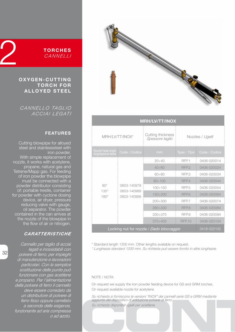
Cutting blowpipe for alloyed steel and stainlesssteel with
iron powder.With simple replacement of
nozzle, it works with acetylene, propane, natural gas and
Tetrene/Mapp gas. For feeding of iron powder the blowpipe
must be connected with a powder distributor consisting of: portable trestle, container
for powder with cyclone dosing device, air dryer, pressure
reducing valve with gauge, oil separator. The powder
contained in the can arrives at the nozzle of the blowpipe in
the flow of air or nitrogen.
CARATTERISTICHE
Cannello per taglio di acciai legati e inossidabili con
polvere di ferro; per impieghi di manutenzione e lavorazioni
particolari. Con la semplice sostituzione delle punte può funzionare con gas acetilene
e propano. Per l’alimentazione della polvere di ferro il cannello
deve essere corredato da un distributore di polvere di ferro fisso oppure carrellato
a seconda delle esigenze, funzionante ad aria compressa
o ad azoto.
O X Y G E N - C U T T I N G T O R C H F O R
A L L O Y E D S T E E L
C A N N E L L O TA G L I O A C C I A I L E G AT I
T O R C H E SC A N N E L L I
* Standard length 1200 mm. Other lengths available on request.* Lunghezza standard 1200 mm. Su richiesta può essere fornito in altre lunghezze.
MRH/LV/TT/INOX
MRh/lv/TT/INOx* Cutting thicknessSpessore taglio Nozzles / Ugelli
Nozzle head angleAngolazione testa Code / Codice mm Type / Tipo Code / Codice
90°
135°
180°
0603-140979
0603-140989
0603-140999
20÷40 RFP.1 0406-020014
40÷60 RFP.2 0406-020024
60÷80 RFP.3 0406-020034
80÷100 RFP.4 0406-020044
100÷150 RFP.5 0406-020054
150÷200 RFP.6 0406-020064
200÷300 RFP.7 0406-020074
280÷330 RFP.8 0406-020084
330÷370 RFP.9 0406-020094
370÷400 RFP.10 0406-020104
Locking nut for nozzle / Dado bloccaggio 0418-022102
NOTE / NOTA:
On request we supply the iron powder feeding device for GS and GRM torches. On request available nozzle for acetylene
Su richiesta si forniscono le versioni "INOX" dei cannelli serie GS e GRM mediante aggiunta del dispositivo di adduzione polvere di ferro.Su richiesta disponibili ugelli per acetilene.

33
R E L AT E D A C C E S S O R I E S O X Y G E N - C U T T I N G T O R C H F O R A L L O Y E D S T E E L
A C C E S S O R I C O R R E L AT I P E R C A N N E L L I TA G L I O A C C I A I L E G AT I
T O R C H E SC A N N E L L I
IRON POWDER high density powder with low content of Oxides and regular round particle shape.Suitable for stainless steels and high alloyed steels cutting process and for special maintenance applications. For powder feeding device to be used on cutting torches.
POLVERE DI FERRO Ad alta densità e basso contenuto di ossidi con particelle di forma regolare rotonda.Specifica per l'impiego su cannelli nelle operazioni di taglio acciai inossidabili ed alto legati nonché per lavoridi manutenzione.Da impiegarsi con cannello provvisto di apposito dispositivo di adduzione e distributore polvere di ferro.
POWDER FEEDING DEVICE WITH/WITHOUT WHEELSDISTRIBUTORI POLVERE FERRO FISSI O CARRELLATI
Code / Codice
CapacityCapacità
Type of gasTipo di gas
With wheelsCarrellato
Without wheels
Non carrellato
50 kgAir / Aria 0651-106048 0651-106088
nitrogen / azoto 0651-106069 0651-106109
IRON POWDER / POLVERE DI FERRO
Apparent densityDensità apparente
Packing / Confezioni Code / Codice
g/cm3 Bags / Sacchetti Pallet / Bancale
3,7 25 kg 1000 kg 0651-106200

34
CONTESSI SERVIZIIl valore di un investimento in attrezzature è in relazione all’esistenza di “supporti” che lo mantengano valido per lungo tempo. Essenzialmente consistono in: manutenzione, agibilità, assenza di rischi da “fermo macchina”
CONTESSI SERVICESThe value of an investment in equipment is related to the existence of “support” which ensures its reliability for a long period. It consists basically of maintenance, operating capability, absence of the risk of “machine downtime”
CONTESSI knows that every customer has his own particular problems; problems that spring up and change constantly. For this reason we have devised unique solutions as part of our consultancy service.The customer already says “let’s talk to CONTESSI about it” and this trend will increase even more; he will have information on new technology, new solutions to old problems, the forefront of new technology.The economic and financial aspects of proposals will be fully evaluated.
CONTESSI sa che ogni utente ha i suoi particolari problemi, che continuamente sorgono e variano; pertanto a questo servizio sono dedicate cure particolari.Già oggi il cliente dice, ma ancor più dirà, “Parliamone a CONTESSI”; e avrà informazioni su nuove tecnologie, su nuove soluzioni di vecchi problemi, su nuove tecniche di impiego. Saranno valutati gli aspetti economici e finanziari delle proposte.
Consultancy Consulenza
The problems connected to “after sales” are considered by CONTESSI to be a testing ground for its own efficiency. The owner of a CONTESSI machine is never left waiting when maintenance, inspection, improvements or advice are required.Skilled personnel and equipment are at the disposal of customers.Courtesy and attention to detail characterise this service.
I problemi connessi alla “post vendita” sono considerati da CONTESSI come banco di prova dalla propria efficienza. Il possessore di una attrezzatura CONTESSI non è mai lasciato solo quando si tratta di verifiche, manutenzione, miglioramenti o consigli.Tecnici e attrezzature sono a disposizione degli utenti. Cortesia e attenzione caratterizzano questo servizio.
After-sales Assistenza

35
H E AT I N GR I S C A L D O
• air-gas burners bruciatori aerogas
• oxy-fuel burners bruciatori ossigas
2

36
FEATURES
hand use air/gas burners.These burners are light and
easy-to-use equipment, suited for all applications which require
a concentrated and efficient heat source. They are used for
metal folding, tempering and material detachment or for
preheating operations of metal moulds, shells, ladles, etc.
They can operate with methane or propane gas. On request available with flame control
system The safety device, with thermocouple controlled valve, shut off gas feeding if the flame
is accidentally extinguished.
CARATTERISTICHE
bruciatori manuali con premiscelazione aria-gas
Idonei per tutti gli impieghi ove necessiti una fonte
di calore concentrata ed efficiente. bruciatori leggeri e maneggevoli. Adatti per i
processi di preriscaldo (siviere, conchiglie, stampi, ...), per le
operazioni di piegatura, tempra e distacco di materiali. Possono funzionare a metano o propano.
A richiesta disponibili con sistema di controllo di fiamma
Muniti di valvola comandata da termocoppia che interrompe
il flusso del gas in caso di spegnimento accidentale.
B U R N E R Sb R U C I AT O R I
A I R - G A S H E AT I N G E Q U I P M E N T
AT T R E Z Z AT U R A R I S C A L D O A E R O G A S
AIR-GAS BURNERS FOR HAND USEBRUCIATORI AEROGAS PER USO MANUALE
Features / Caratteristiche Standard range ( indicative )
heating PowerPotenza di riscaldo
40.000 -100.000 kcal/h
Fuel gas pressure / Pressione gas 20 - 100 Mbar
Fuel gas FlowPortata Gas combustibile
5 - 12,5 m³/h
Air pressure / Pressione aria 2 - 4 bar
Air Flow / Portata aria 12 - 30 m³/h
Standard lengthLunghezza standard
600 - 1000 mm
burner angleAngolazione bruciatore
90° - 180°
bonnet diameterDiametro campana
50 - 110 mm
All CONTESSI burners could be customized with more heads and different frame shape (round, square..) in order to increase the productivity.
I bruciatori CONTESSI possono essere personalizzati adattando le varie caratteristiche alla specifica applicazione a cui sono destinati, per esempio aumentando le teste e variando la forma del telaio (rotonda, quadrata..).

37
FEATURES Forged brass body. brass handwheels and connections. Stainless steel stems and teflon gaskets. Connections for ø 8mm hoses (gas 3/8”bSP lh thread – oxygen 3/8”bSP Rh thread).
CARATTERISTICHE Gruppo rubinetti, raccordi e volantini in ottone stampato. Rubinetti con asticelle inox e guarnizioni in teflon. Portagomma smontabili per tubi ø 8mm (gas 3/8”G sx – ossigeno 3/8”G dx).
O X Y F U E L H E AT I N G E Q U I P M E N T
AT T R E Z Z AT U R A R I S C A L D O O S S I G A S
EH SERIES HANDGRIP / IMPUGNATURA SERIE EH
Model / Modello Length / Lunghezza Code / Codice
Eh. 50 230 mm 0610-220505
“EH” LANCE FOR H SERIES HEATING NOZZLELANCIA “EH” PER PUNTA DA RISCALDO SERIE H
Flow/deliverErogazione
Model / n°n° Modello
Lance Code (with nozzle)
Codice Lancia (completadi punta)
Nozzle Punta
Nozzle codeCodice punta
3.500 lt/h Eh-h.2 0614-240425 h.2 0414-023784
6.000 lt/h Eh-h.3 0614-240435 h.3 0414-023794
7.500 lt//h Eh-h.4 0614-240445 h.4 0414-023804
10.000 lt//h Eh-h.5 0614-240455 h.5 0414-023814
B U R N E R Sb R U C I AT O R I
CONTESSI SERVIZIIl valore di un investimento in attrezzature è in relazione all’esistenza di “supporti” che lo mantengano valido per lungo tempo. Essenzialmente consistono in: manutenzione, agibilità, assenza di rischi da “fermo macchina”
CONTESSI SERVICESThe value of an investment in equipment is related to the existence of “support” which ensures its reliability for a long period. It consists basically of maintenance, operating capability, absence of the risk of “machine downtime”
leafing through the catalogue one is struck by the imposing range of spares necessary for all the equipment manufactured. There are thousands and thousands of parts available, right down to the smallest seal. Computer controlled parts availability serves the CONTESSI user in his every need. CONTESSI considers the ready availabilty of original spares to be its true market strength. This is probably the major reason for its customer loyalty. When evaluating the cost benefit of a purchase the new customer must consider this point carefully; the old customer does not have to.
Sfogliando il catalogo si è colpiti dalla gamma imponente di ricambi necessari per tutte le attrezzature prodotte. Sono migliaia di pezzi, sino alla minima guarnizione, la cui disponibilità, pilotata da un computer, serve l’utente CONTESSI in ogni sua esigenza. La pronta disponibilità di ricambi originali è ritenuta da CONTESSI un vero punto di forza: è anche motivo di fedeltà della propria Clientela.Nel valutare la convenienza di un acquisto il nuovo Cliente deve considerare con attenzione questo punto: il vecchio non ne ha bisogno.
Spares Ricambi
It is wrong to assume that research is not the province of smaller companies who do not have the large cash resources. In fact, CONTESSI has an active research programme and maintains constant contact, in every way, with the leading worldwide innovators of technological developments in the field. The most important meetings of technical and managerial staff are followed, often in person. Specialised fairs and exhibitions are followed in detail. The best technical publications are received and analysed.An enormous volume of information is converted into new projects, improvements, investments. Even the smallest of customers is kept in touch with all this work and the resultant new equipment.
Erronea l’idea che non sia applicabile ad aziende minori che non dispongono di fondi per questa voce. CONTESSI invece fa attiva ricerca mantenendo costanti contatti, in tutti i modi, con i massimi promotori degli sviluppi tecnologici del ramo nel mondo. I più importanti convegni di tecnici e di managers lo trovano, spesso di persona, presente. Fiere e mostre specializzate sono seguite puntualmente. Le migliori pubblicazioni tecniche sono ricevute e analizzate.Una massa ingente di informazioni si traduce in nuovi progetti, miglioramenti, investimenti. La Clientela più qualificata è tenuta al corrente di tutto questo lavoro e delle nuove apparecchiature che ne derivano.
Reserch Ricerca
38

39
P L A N T E Q U I P M E N TI M P I A N T I S T I C A
• hoses tubi flessibili
• take-up reels avvolgitori
• pressure regulators riduttori di pressione
• pressure reducing boxes cassette di riduzione per posti di lavoro
• filters filtri anti impurità
• solenoids elettrovalvole
• shut-off valves valvole di intercettazione
• modular panel systems pannelli modulari di comando
2

40
FEATURES
Our flexible hoses are particularly recommended
for oxygen. Resistant to ozone and abrasion, their
surface in contact with the gas is particularly smooth. Manufactured out of self-
extinguishing rubber (ASTM-C542) and according
to EN-ISO 3821 (replacing UNI EN 559). Operating pressure 25
bar (40 bar on request). brass running nut connections at
both ends with spherical seat attachment.
CARATTERISTICHE
I nostri tubi flessibili sono particolarmente indicati per
l’ossigeno. Resistenti all’ozono e all’abrasione, hanno la
superficie a contatto con il gas particolarmente liscia. Realizzati
in materiale autoestinguente a norma ASTM-C542 e conformi
alla norma EN-ISO 3821 (ex UNI EN 559). Pressione
esercizio 25 bar (a richiesta 40 bar). Con raccordi femmina
girevoli e portagomma a sede sferica in ottone alle due
estremità del tubo.
S E L F -E X T I N G U I S H I N G
F L E X I B L E H O S E S
T U b I F L E S S I b I L I A U T O E S T I N G U E N T I P E R A P P L I C A Z I O N I
D I V E R S E
The spiral (supplied on request) protects the end part of the hose from throttling, wearing and cracking near the connection.
Il tortiglione (fornito a richiesta) protegge dallo strozzamento la parte terminale del tubo più esposta al logoramento e soprattutto impedisce la rottura del tubo stesso in corrispondenza del portagomma.
Also available hoses for Carbon powder, other fluids and sizes, and in different materials. Detailed bulletin on request.
Disponiamo di tubi per Polvere di Carbone, per altri fluidi, altri diametri e pressioni, e in materiali diversi.A richiesta è disponibile apposito catalogo dettagliato.
For enquiries and quotes refer to CONTESSI Configuration Code for flexible hoses.
Per richieste di informazioni e preventivi vi invitiamo ad utilizzare il Codice di configurazione per tubi flessibili CONTESSI.
hose type: Standard (up to 25 bar) S Tipo tubo: standard (fino a 25 bar)
length: 20 m) E Lunghezza: 20 m
Fluid: Oxygen O Fluido: Ossigeno
Internal diameter: 13 mm C Diametro interno: 13 mm
braiding: Metal braiding M Rivestimento esterno: Calza metallica
kinkless spiral: at outlet end U Tortiglione antipiega: all’estremitàdi uscita
Inlet coupling: bSP ½” Rh D Raccordo di entrata: ½” GAS Dx
Outlet coupling: bSP ½” Rh D Raccordo di uscita: ½” GAS Dx
hose tail fastening: std crimping ferrule S Fissaggio portagomma: boccola a
pressare std
SEOCMUDDS
Configuration code example / Esempio di configurazione
H O S E ST U b I

41
H O S E ST U b I
C O N F I G U R AT I O N C O D E F O R F L E X I B L E H O S E S
C O D I C E D I C O N F I G U R A Z I O N E P E R T U b I F L E S S I b I L I C O N T E S S I
locate among the values in the grey cells those corresponding to the required features, and generate your custom configuration code observing the indicated position.
Comporre il codice selezionando, fra i valori nelle celle grigie, quelli corrispondenti alle caratteristiche desiderate.
LENGTH LUNGHEZZA
A 2 m
b 5 m
C 10 m
D 15 m
E 20 m
F 30 m
G 40 m
x custom a richiesta
FLUIDFLUIDO
O Oxygen/Ossigeno
A Acetylene/Acetilene
M Methane ( natural gas ) / Metano
P GPl PropanePropano GPL
D Compressed AirAria compressa
x Other Fluids Altri fluidi
INTERNAL ØØ INTERNO
A 8 mm
b 10 mm
C 13 mm
D 16 mm
E 20 mm
F 25 mm
G 32 mm
h 40 mm
Hose tail FASTENINGFISSAGGIO PORTAGOMMA
SStandard (crimping ferrule)boccola a pressare
R
Reusable * (high Pressure) Riutilizzabile * (per alta pressione)
* Only for hose ø up to 13mmPer tubi ø fino a 13mm
HOSE TYPETIPO DI TUBO
S
Standard hoseTubo standard(up to 25 bar)
RReinforced Rinforzato(up to 40 bar)
BRAIDINGRIVESTIMENTO
0 NoneAssente
M
Metal braiding Treccia metallica
F Fiberglass * Vetroresina *
* Not forReinforced hosesSolo per Tubi di tipo Standard
KINKING SPIRALTORTIGLIONE
ANTIPIEGA
0 NoneAssente
E At Inlet end All’entrata
U At Outlet end All’uscita
2 bothEntrambi
Code positions
CODING kEy ChIAVE DI CODIFICA
Code Posit. / Posiz. nel cod. 7 inlet / entrata - 8 outlet / uscita
4
FeaturesCaratteristiche
Coupling (bsp) - Female swivel nut with hose tailFiletto raccordo (gas) - Dado femmina girevole su portagomma
hO
SE
int.
ø in
tern
o tu
bo [m
m]
Value 3/8" 1/2" 3/4" 1" 1"1/4 1"1/2 2"
8
lh Rh lh Rh lh Rh lh Rh lh Rh lh Rh lh Rh
A b C D E F G h j k l M N P
A • • • • • •10 b • • • • • •13 C • • • •16 D • • • •20 E • •25 F •32 G •40 h •
Valore
Available connections depending on hose diameter Raccordi disponibili per i diversi diametri di tubo
1 2 3 4 5 6 7 8 9
THREAD (BSP) FILETTATO (GAS)
A 3/8" lh – Sx
b 3/8" Rh - Dx
C 1/2" lh – Sx
D 1/2" Rh - Dx
E 3/4" lh – Sx
F 3/4" Rh - Dx
G 1" lh – Sx
h 1" Rh - Dx
j 1"1/4 lh – Sx
k 1"1/4 Rh - Dx
l 1"1/2 lh – Sx
M 1"1/2 Rh - Dx
N 2" lh – Sx
P 2" Rh - Dx

42
FEATURES
Manufactured out with two self-extinguishing hoses (ASTM-C542)
joined together by cable-ties. Suitable for Oxygen and all non
corrosive Gases for welding and cutting. According to EN-ISO
3821 standard (replacing UNI-EN 559). Ageing and abrasion
resistant. Operating pressure 25 bar. Recommended for heavy
duty and for applications in harsh environments. Running nut
connection for easy installation.
CARATTERISTICHE
Realizzati con due tubi flessibili autoestinguenti (ASTM-C542)
accoppiati e fissati mediante fascettatura. Idonei all’impiego
con gas compressi non corrosivi nei posti di saldatura e ossitaglio. Conformi alla normativa EN-ISO
3821 (ex UNI-EN 559). Altamente resistenti all’invecchiamento e
all’abrasione. Pressione di esercizio 25 bar. Consigliati per l’utilizzo
intensivo e per l’impiego in ambienti difficili. Raccordi femmina girevoli in
ottone montati alle due estremità.
S E L F -E X T I N G U I S H I N G
F L E X I B L E D O U B L E H O S E S F O R
C U T T I N G T O R C H E S
T U b I F L E S S I b I L I A U T O E S T I N G U E N T I
A C C O P P I AT I P E R C A N N E L L I
On request we can supply twin-hoses according to EN 559 / 3821 standard, for light-duty works.
Su richiesta forniamo tubo binato per cannelli conforme alla normaEN 559 / 3821, idoneo per condizioni operative non gravose.
For enquiries and quotes refer to CONTESSI Configuration Code for flexible hoses.
Per richieste di informazioni e preventivi vi invitiamo ad utilizzare il Codicedi configurazione per tubi flessibili CONTESSI.
hose type: Coupled A Tipo tubo: Accoppiato
length: 30 m F Lunghezza: 30 m
Fuel Gas: Methane (Natural Gas) M Combustibile: Gas Metano
Oxygen hose diameter (internal):13 mm C Diametro Tubo Ossigeno (interno):
13 mm
Fuel gas hose diameter (internal): 10 mm B Diametro Tubo Gas Combustibile (int.):
10 mm
Oxygen-hose Inlet connection:bSP ½” Rh C Raccordo Entrata Ossigeno:
½” GAS Dx
Fuel-gas hose Inlet connection:bSP ½” lh D Raccordo Entrata Gas combustibile:
½” GAS Sx
Oxygen-hose Outlet connection: bSP ½” Rh C Raccordo Uscita Ossigeno:
½” GAS Dx
Fuel-gas hose Outlet connection: bSP ½” lh D Raccordo Uscita Gas combustibile:
½” GAS Sx
AFMCBCDCD
Configuration code example / Esempio di configurazione
H O S E ST U b I

43
H O S E ST U b I
C O N F I G U R AT I O N C O D E F O R D O U B L E -H O S E S
C O D I C E D I C O N F I G U R A Z I O N E P E R T U b O A C C O P P I AT O C O N T E S S I
LENGTH LUNGHEZZA
A 2 m
b 5 m
C 10 m
D 15 m
E 20 m
F 30 m
G 40 m
x custom a richiesta
HOSE TYPETIPO di TUBO
A Double hoses Accoppiato
C
braided double hosesRivestito accoppiato
O2 HOSE Ø (internal)Ø Tubo O2 (interno)
A 8 mm
b 10 mm
C 13 mm
FUEL GASGAS
COMBUSTIBILE
MMethane(natural gas)Metano
P GPl PropanePropano GPL
FUEL HOSE CONNECTIONS (BSP)
RACCORDI TUBOGAS COMB. (GAS)
A 3/8" lh – Sx
C 1/2" lh – Sx
E 3/4" lh – Sx
Code positions
CODING kEy ChIAVE DI CODIFICA
Code PositionPosizione nel codice
6 - 8 OxyGEN hOSE CONNECTIONSRACCORDI TUbO OSSIGENO
7 - 9FUEl GAS hOSE CONNECTIONS
RACCORDI TUbO GAS
4/5
FeaturesCaratteristiche
Coupling (bsp) - Female swivel nut with hose tailFiletto raccordo (gas) - Dado femmina girevole su portagomma
hose
int.ø
ø in
tern
otu
bo [m
m]
Value 3/8" 1/2" 3/4" 3/8" 3/4" 1"1/2
8
Rh Dx Rh Dx Rh Dx lh Sx lh Sx lh Sx
b D F A C E
A • • • • • •10 b • • • • • •13 C • •
Valore
Available connections depending on hose diameter Raccordi disponibili per i diversi diametri di tubo
FUEL HOSE Ø (internal)
Ø TUBO GAS COMBUSTIBILE
(interno)
A 8 mm
b 10 mm
C 13 mm
not exceeding oxygen-hose ø
non superiore al ø del tubo O2
O2 HOSE CONNECTIONS (BSP)RACCORDI Tubo O2
(GAS)
b 3/8" Rh - Dx
D 1/2" Rh - Dx
F 3/4" Rh - Dx
INlET OUTlET
INlET OUTlET
1 2 3 4 5 6 7 8 9
locate among the values in the grey cells those corresponding to the required features, and generate your custom configuration code observing the indicated position.
Comporre il codice selezionando, fra i valori nelle celle grigie, quelli corrispondenti alle caratteristiche desiderate.

44
FEATURES
Take-up reel for one flexible hose under pressure, with automatic drum
stop (except for the 191 series) and hose pay-off device.
Galvanized plate construction. Pressure-tight rotary seals. by using the take-up attachment, the hoses are not left lying on the factory floor
where they could become damaged when heavy objects are shifted
around, thus ensuring complete safety for the operators. Can be used
not only for non-corrosive process gases, but also for water, air, oil
and other fluids (provided they are non-corrosive). The pivot bracket
(supplied on request) allows the take-up reel to be rotated in order to fix it
in the most suitable working position.
CARATTERISTICHE
Avvolgitore per 1 tubo flessibile sotto pressione, con dispositivo automatico per l’arresto (ad esclusione della serie 191) ed il riavvolgimento. Costruzione
in lamiera zincata. Giunti girevoli a perfetta tenuta di pressione.
L’impiego dell’avvolgitore elimina il tubo sul pavimento evitando così
che venga tranciato durante lo spostamento di materiali e garantisce la massima sicurezza per gli operatori. Oltre che per gas tecnici non corrosivi possono essere impiegati per acqua
aria - olio ed altri fluidi (sempre non corrosivi). Il supporto orientabile (opzionale) consente di ruotare
l’avvolgitore per fissarlo nella più idonea posizione di lavoro.
TA K E - U P R E E L F O R O N E F L E X I B L E H O S E
AV V O L G I T O R E P E R U N T U b O F L E S S I b I L E
TA K E - U P R E E L SAV V O L G I T O R I
TAKE-UP REEL FOR ONE FLEXIBLE HOSEAVVOLGITORE PER UN TUBO FLESSIBILE
SeriesSerie
Coupling inlet/outlet (BSP)Raccordo
entrata/uscita (GAS)
Max øof hose
ø Esterno massimodel tubo
Max hose length
Lunghezza massimadel tubo
Dimensions / Dimensioni
h l T IMCode / Codice
116* 3/4” Dx 23 15 500 300 350 480 0650-261169
131* 3/4” Dx 23 30 500 300 350 480 0650-261319
D/161N 3/4” Dx 23 30 300 550 520 575 0650-261589
E/161N 1” Dx 31 30 300 550 520 575 0650-261629
F/161N 1”1/4 Dx 37 20 300 550 520 575 0650-261759
G/161N 1”1/2 Dx 47 20 300 550 520 575 0650-261879
F/191N 1”1/4 Dx 37 30 300 550 720 785 0650-261819
G/191N 1”1/2 Dx 47 30 300 550 720 785 0650-261839
h/191N 2” Dx 59 10 320 510 810 970 0650-262009
* Take-up reels 116 and 131 are constructed with box. The support bracket for use with the type 116 and 131 (supplied on request) is code 0650-260100 (see page 45)
* Gli avvolgitori 161 e 131 sono del tipo a cassa e possono essere dotatidel supporto cod. 0650-260100 (vedi pag. 45)
Supplied on request, not available for 191 series modelsOpzionale, non disponibile per i modelli della serie 191
Other lengths and diameters of hose available on request.A richiesta sono fornibili anche per tubi di lunghezze e diametri diversi.
Protection dome and hose roller guide (supplied on request, available for 161 and 191 series models).
Cupolino di protezione e guidatubo (opzionali, disponibili peri modelli delle serie 161 e 191).
Swivel bracket / Supporto orientabile 0650-260150
l
IM
h
ØT

45
D O U B L E H O S ETA K E - U P R E E L
AV V O L G I T O R EP E R D U E T U b I F L E S S I b I L I
FEATURES Take-up reels for 2 flexible hoses under pressure, with automatic stop and hose pay-off device. Galvanized plate construction.Pressure-tight rotary seals. Essential for the welding, oxygen cutting and scarfing shop. by using the take-up attachment, hoses are not left lying on the factory floor where they could become damaged when heavy objects are shifted around, thus ensuring complete safety for the operators. Can be used not only for non-corrosive process gases, but also for water, air, oil and other fluids (provided they are non-corrosive).
CARATTERISTICHE Avvolgitore per 2 tubi flessibili sotto pressione, con dispositivo automatico per l’arresto ed il riavvolgimento. Costruzione in lamiera zincata. Giunti girevoli a perfetta tenuta di pressione.Indicato nei posti di saldatura, ossitaglio e scriccatura.L’impiego dell’avvolgitore elimina il tubo sul pavimento evitando così che venga tranciato durante lo spostamento di materiali e garantisce la massima sicurezza per gli operatori. Oltre che per gas tecnici non corrosivi possono essere forniti per acqua - aria - olio ed altri fluidi (sempre non corrosivi).
DOUBLE HOSE TAKE-UP REELAVVOLGITORE PER DUE TUBI FLESSIBILI
SeriesSerie
Coupling inlet/outlet (BSP)
Raccordo entrata/uscita (GAS)
Max øof hose
ø Esterno massimodel tubo
Max hose length
Lunghezza massimadel tubo
Dimensions / Dimensioni
h l T IMCode / Codice
216
Oxygen/Ossigeno3/8” Dx
16 15500 300 350 480 0650-262169
gas 3/8” Sx 17 15
231
Oxygen/Ossigeno3/8” Dx
16 30500 300 350 480 0650-262319
gas 3/8” Sx 17 30
261*
Oxygen/Ossigeno3/4” Dx
31 30300 550 520 575 0650-262619
gas 3/8” Sx 19 30
* Take-up reel 261 is constructed without box. The support bracket for use with the type 261 (supplied on request) is code 0650-260150 (see page 44)
* L’avvolgitore 261 è del tipo senza cassa e può essere dotatodel supporto cod. 0650-260150 (vedi pag. 44)
Supplied on request / Opzionale
Swivel bracket / Supporto orientabile 0650-260100 TA K E - U P R E E L SAV V O L G I T O R I
Wall bracket / templateDima / Supporto fissaggio a parete 0650-260120
Other lengths and diameters of hose available on request.A richiesta sono fornibili anche per tubi di lunghezze e diametri diversi.
For an easy and quick installation of the take-up reel.Per una semplice e veloce installazione dell'avvolgitore.

46
FEATURES
Suitable for single gas-cylinder. With filter and safety valve. With
h.P. and l.P. gauges.
CARATTERISTICHE
Riduttore di pressione a semplice espansione per gas
non corrosivi indicato per singole bombole.
P R E S S U R ER E D U C I N G VA LV E S
F O R G A S - C Y L I N D E R
R I D U T T O R ID I P R E S S I O N EP E R b O M b O L E
579 SERIES: Construction material: Brass. Inlet connection port for cylinder.Countersunk seat outlet 3/8” BSP male.SERIE 579: Costruzione in ottone. Entrata attacco bombola.Uscita sede svasata filettatura 3/8" GAS maschio.
579
SeriesSerie
FluidFluido
Inlet pressurePressionedi entrata
Gauge/inletManometro
entata
OutletpressurePressionedi uscita
Gauge/outlet
Manometrouscita
Max flow
Portata massima
Code / Codice
bar bar bar bar Nm³/h
579
oxygenossigeno 200 0÷315 8 0÷16 35 0624-315791
acetyleneacetilene 40 0÷60 1,5 0÷6 8 0624-315792
To allow us to offer you the pressure regulator that best suits your needs always indicate following information when requesting information or a quotation
Per agevolarci nella scelta del riduttore di pressione più adatto alle vostre specifiche esigenze, indicare sempre I seguenti dati nelle richieste di informazioni o preventivi.
Inlet Pressure Pressione in ingresso
Required Outlet Pressure Pressione richiesta in uscita
Fluid / Media Fluido
Connection (flange / thread) Attacchi (flangiati / filettati)
Flow rate (or use) Portata o utilizzo
PRESSURE REGULATORSRIDUTTORI DI PRESSIONE

R.1100*
Series / Serie
Inlet pressurePressionedi entrata
Gauge/inletManometro
entata
OutletpressurePressionedi uscita
Gauge/outlet
Manometrouscita
Max flow
Portata massima
Code / Codice
bar bar bar bar Nm³/h
R.1100 hAq 220 0÷315 0,8÷8 0÷16 70 0624-311101
R.1100 hbq 220 0÷315 1,5÷15 0÷25 155 0624-311111
R.1100 hCq 220 0÷315 3÷30 0÷100 210 0624-311121
R.1100 hDq 220 0÷315 5÷50 0÷100 300 0624-311131
47
FEATURES Suitable for decompression and distribution plants with sets of cylinders. With filter and safety valve. With h.P. and l.P. gauges.
CARATTERISTICHE Riduttore di pressione a semplice espansione per gas non corrosivi indicato per impianti di decompressione e distribuzione gas con pacchi bombole.
R.121B Series: Aluminium body and bonnet. Inlet connection port for propane cylinder. Countersunk seat outlet 1/2” BSP male.Serie R.121b : Corpo e campana in alluminio. Entrata attacco bombola propano.Uscita sede svasata filettatura 1/2” GAS maschio.
* Suitable for OxyGEN. On request available for different gas. Idoneo per uso OSSIGENO. Su richiesta disponibile per altri gas.
R.121 B
Series / SerieInlet pressure
Pressionedi entrata
OutletpressurePressionedi uscita
L.P. gaugeManometro
Max flow
Portata massima
Code / Codice
bar bar bar Nm³/h
R.121 E2 30 1,5÷15 0÷25 400 0624-31121bE2
R.1100 SERIESInlet connection port for cylinder; outlet connection 3/8" or 1/2" BSP male, on request.SERIE R.1100Entrata attacco bombola; uscita sede svasata 3/8" o 1/2" GAS maschio,a richiesta.
P R E S S U R ER E D U C I N G VA LV E SF O R S E T S O F C Y L I N D E R S
R I D U T T O R ID I P R E S S I O N EP E R PA C C h I b O M b O L E
PRESSURE REGULATORSRIDUTTORI DI PRESSIONE

48
FEATURES
Suitable for decompression and distribution plants. With filter
and safety valve. With h.P. and l.P. gauges.
CARATTERISTICHE
Riduttore di pressione a semplice espansione per gas non corrosivi particolarmente
indicato per impiantidi decompressionee distribuzione gas.
M A N I F O L D P R E S S U R E
R E D U C I N G VA LV E S
R I D U T T O R I P E R C E N T R A L I D I
P R E S S I O N E P E R I M P I A N T I
R.300 SERIES - Inlet/outlet connection 3/4” BSP maleSERIE R.300 - Attacchi entrata/uscita 3/4” GAS maschio
R.300*
Series / Serie
Inlet pressurePressionedi entrata
Gauge/inletManometro
entata
OutletpressurePressionedi uscita
Gauge/outlet
Manometrouscita
Max flow
Portata massima
Code / Codice
bar bar bar bar Nm³/h
R.300 hA 220 0÷315 0,8÷8 0÷16 600 0624-313001
R.300 hb 220 0÷315 1,5÷15 0÷25 720 0624-313011
R.300 hC 220 0÷315 3÷30 0÷63 850 0624-313021
R.300 hD 220 0÷315 5÷50 0÷100 1000 0624-313031
R.1000 Series - Inlet /outlet connection 1” BSP maleSerie R.1000 - Attacchi in entrata e uscita 1” GAS maschio
R.1000*
Series / Serie
Inlet pressurePressionedi entrata
Gauge/inletManometro
entata
OutletpressurePressionedi uscita
Gauge/outlet
Manometrouscita
Max flow
Portata massima
Code / Codice
bar bar bar bar Nm³/h
R.1000 hA 220 0÷315 0,8÷8 0÷16 1100 0624-311001
R.1000 hb 220 0÷315 1,5÷15 0÷25 1300 0624-311011
R.1000 hC 220 0÷315 3÷30 0÷60 1500 0624-311021
R.1000 hD 220 0÷315 5÷50 0÷100 1650 0624-311031
PRESSURE REGULATORSRIDUTTORI DI PRESSIONE
* Suitable for OxyGEN. On request available for different gas. Idoneo per uso OSSIGENO. Su richiesta disponibile per altri gas.
* Suitable for OxyGEN. On request available for different gas. Idoneo per uso OSSIGENO. Su richiesta disponibile per altri gas.

49
P R E S S U R E R E D U C I N G VA LV E S F O R G A S D I S T R I B U T I O N S Y S T E M
R I D U T T O R ID I P R E S S I O N EP E R R E T E D I S T R I b U Z I O N E G A S
FEATURES The pressure reducing valves listed are specially designed for use in steelworks and are necessary to reduce and stabilize the pressure from the mains to the operating level.Recommended for: oxygen cutting torches, machines, quick intervention torches for continuous casting and slag/scrap break-up work, thermal lances, oxygen lances.
CARATTERISTICHE I riduttori elencati sono particolarmente indicati per impiego su impianti siderurgici e sono necessari per ridurre e stabilizzare la pressione dalla rete a quella di utilizzo. Indicati per:cannelli ossitaglio, macchine, cannelli pronto intervento su colata continua e demolizione, per lance termiche, lance per ossigeno.
R.121
Series / Serie
Inlet pressurePressionedi entrata
OutletpressurePressionedi uscita
L.P. gaugeManometro
Max flow
Portata massima
Code / Codice
bar bar bar Nm³/h
R.121 C1(1) 30 0,8÷8 0÷16 350 0624-311211C1
R.121 E1(1) 30 1,5÷15 0÷25 425 0624-311211E1
R.121 C2(2) 30 0,8÷8 0÷16 350 0624-311214C2
R.121 E2(2) 30 1,5÷15 0÷25 400 0624-311214E2
NOTE / NOTA:1) brass body and bonnet: suitable for OxyGEN1) Corpo e campana in ottone: per OSSIGENO e altri gas
2) Aluminium body: OxyGEN escluded2) Corpo e campana in alluminio: OSSIGENO escluso
R.123
Series / Serie
Inlet pressurePressionedi entrata
OutletpressurePressionedi uscita
L.P. gaugeManometro
Max flow
Portata massima
Code / Codice
bar bar bar Nm³/h
R.123 C1(1) 30 0,8÷8 0÷16 1200 0624-311231C1
R.123 E1(1) 30 1,5÷15 0÷25 1600 0624-311231E1
R.123 C2(2) 30 0,8÷8 0÷16 1200 0624-311234C2
R.123 E2(2) 30 1,5÷15 0÷25 1600 0624-311234E2
NOTE / NOTA:1) brass body: suitable for OxyGEN1) Corpo in ottone: per OSSIGENO e altri gas
2) Aluminium body: OxyGEN escluded2) Corpo in alluminio: OSSIGENO escluso
R.121 SERIES: Inlet/Outlet connections 1/2" BSP ports female.On request, available with flanges.SERIE R.121: Attacchi entrata/uscita con filettatura 1/2" GAS femmina. A richiesta disponibile con connessioni flangiate.
R.123 SERIES: Inlet/Outlet connections 1" BSP ports female.On request, available with flanges.SERIE R.123: Attacchi entrata/uscita con filettatura 1" GAS femmina.A richiesta disponibile con connessioni flangiate.
PRESSURE REGULATORSRIDUTTORI DI PRESSIONE

50
FEATURES
Common characteristics: body and cross-head made of light alloy with chemical nickel treatment allowing them to be
used with any kind of non-corrosive gas. Mod.128 is also
made in bronze. Complete with high and low pressure-gauges
and incorporated stainless steel filter. large flow pressure
regulators may be controlled via a pilot pressure reducing valve.
CARATTERISTICHE
Caratteristiche comuni: corpo e cappellotto in lega leggera
con trattamento nickel chimico in modo da poter essere usati
con qualsiasi tipo di gas non corrosivo. Il mod.128 viene costruito anche in bronzo.Completi di manometri di
alta e bassa pressione e filtro incorporato in acciaio inox.
Possibilità di regolazione con riduttore pilota.
H I G H C A PA C I T Y P R E S S U R E
R E D U C I N G VA LV E S
R I D U T T O R ID I P R E S S I O N E P E R
R E T E D I S T R I b U Z I O N E G A S G R A N D I
P O R TAT E
R.130
Series / Serie
Inlet pressurePressionedi entrata
OutletpressurePressionedi uscita
L.P. gaugeManometro Code / Codice
bar bar bar
R.130 F 50 1,5÷15 0÷25 0624-31130F
R.130 G 50 3÷30 0÷60 0624-31130G
R.128 SERIES - Inlet/Outlet connections 2" BSP ports female. On request, available with flanges.SERIE R.128 - Attacchi entrata/uscita con filettatura 2" GAS femmina. A richiesta disponibile con connessioni flangiate.
R.128
Series / Serie
Inlet pressurePressionedi entrata
OutletpressurePressionedi uscita
L.P. gaugeManometro Code / Codice
bar bar bar
R.128 D1(1) 30 1,5÷15 0÷25 0624-311281D1
R.128 D2(2) 20 1,5÷15 0÷25 0624-311284D2
NOTE / NOTA:1) brass body: suitable for OxyGEN1) Corpo in ottone: per OSSIGENOe altri gas
2) Aluminium body: OxyGEN escluded2) Corpo in alluminio: OSSIGENO escluso
R.130 SERIES: Inlet/Outlet connections 1"1/2 BSP ports female. On request, available with flanges.SERIE R.130: Attacchi entrata/uscita con filettatura 1"1/2 GAS femmina. A richiesta disponibile con connessioni flangiate
Max flow rate 4500 Nm³/h (tested with compressed air, Pin = 10 bar, Pout = 3 bar)Portata max 4500 Nm³/h (misurata con aria compressa, Pin = 10 bar, Pout = 3 bar)
Max flow rate 4500 Nm³/h (tested with compressed air, Pin = 10 bar, Pout = 6,5 bar)Portata max 4500 Nm³/h (misurata con aria compressa, Pin = 10 bar, Pout = 6,5 bar)
PRESSURE REGULATORSRIDUTTORI DI PRESSIONE

51
FEATURES Common characteristics: body and cross-head made of light alloy with chemical nickel treatment allowing them to be used with any kind of non-corrosive gas. Mod.128 is also made in bronze. Complete with high and low pressure-gauges and incorporated stainless steel filter. large flow pressure regulators may be controlled via a pilot pressure reducing valve.
CARATTERISTICHE Caratteristiche comuni: corpo e cappellotto in lega leggera con trattamento nickel chimico in modo da poter essere usati con qualsiasi tipo di gas non corrosivo. Il mod.128 viene costruito anche in bronzo.Completi di manometri di alta e bassa pressione e filtro incorporato in acciaio inox.Possibilità di regolazione con riduttore pilota.
H I G H C A PA C I T Y P R E S S U R E R E D U C I N G VA LV E S
R I D U T T O R ID I P R E S S I O N E P E R R E T E D I S T R I b U Z I O N E G A S G R A N D I P O R TAT E
R.126 SERIESBrass body, Aluminium bonnet, Brass inner parts: suitable for OXYGEN and other gases. Inlet/Oulet connections flanges DN100 4".SERIE R.126Corpo in bronzo, campana alluminio, parti interne in ottone: per OSSIGENO e altri gas. Attacchi entrata/uscita flangiati DN100 4".
R.126
Series / Serie
Inlet pressurePressionedi entrata
OutletpressurePressionedi uscita
L.P. gaugeManometro
Max flowPortata
massimaCode / Codice
bar bar bar Nm³/h
R.130 b 30 0,6÷6 0÷16 4500 0624-311261C1
PRESSURE REGULATORSRIDUTTORI DI PRESSIONE

52
FEATURES
The pressure reducing boxes can be connected to the gas
line at each point where oxygen, combustible and inert gasses
are being used. Pressure can be regulated for all purpose gas-
welding, oxy-cutting,heating and electric welding with protected atmosphere.
The protecting boxes are made entirely of stainless steel, with
fixing holes and contain opening-closing valve, reducing valve with
gauge, safety valve, for oxygen and combustible gases.
CARATTERISTICHE
I posti di utilizzo in cassetta vengono collegati alle reti di
distribuzione per ossigeno, gas combustibili o gas inerti.
Per regolare la pressione dei gas nei vari impieghi di saldatura,
ossitaglio, riscaldo e saldatura elettrica con atmosfera protettiva.
Le cassette di protezione sono realizzate in lamiera di acciaio inox
provviste di fori di fissaggio; valvola di intercettazione; regolatore di
pressione con manometro; valvola di sicurezza.
P R E S S U R E R E D U C I N G
B O X E S , F I LT E R S , S O L E N O I D S
C A S S E T T ED I R I D U Z I O N E , F I LT R I ,
E L E T T R O VA LV O L E
PRESSURE REDUCING BOXES, FILTERS, SOLENOIDS
CASSETTE DI RIDUZIONE, FILTRI, ELETTROVALVOLE
* Acetylene 1,5 bar / Acetilene 1,5 bar 1) On requeste with flange / Flangiati a richiesta
FILTERS AGAINST CONTAMINATION AND CONDENSATE FILTRI ANTI-IMPURITÀ
Fluid Media Fluido
Connection Raccordi (1)
Max Operating pressure
Pressione massima di esercizio
Filter Mesh Grado
di filtraggio
CodeCodice
A ( bSP/GAS ) bar
Oxygen Ossigeno
1” F – Rh Dx 40 100 µm 0620-310451
Fuel gas / gas combustibile
1” F – Rh Dx 40 / 1,5* 100 µm 0620-310463
Gas filter for installation in pipelines. Reliable protection against contamination and condensate.
Filtro gas per condutture. Affidabile protezione controle impurità nella linea.
SOLENOIDS - ELETTROVALVOLE
Fluid Media Fluido
Connection Raccordi (1)
Max Operating pressure
Pressione massima di esercizio
Standard Volt. Tensione stand.
CodeCodice
A ( bSP/GAS ) bar
Oxygen Ossigeno
1/2” F - Rh Dx 16 24v DC 0623-390041
Fuel gas / gas combustibile
1/2” F - Rh Dx 10 24v DC 0623-390054
PP23PP21
PRESSURE REDUCING BOXES FOR WORKING PLACESCASSETTE DI RIDUZIONE PER POSTI DI LAVORO
SeriesSerie
Type of gasTipo di gas
Operating pressurePressione
di esercizio
Flow rangePortata
CodeCodice
bar Nm³/h
PPO/21 Oxygen/Ossig. 1,5÷15 40÷110 0640-105811
PPG/21 Fuel gas/Gas comb. 0,8÷8 20÷40 0640-105803
PPO/23 Oxygen/Ossig. 1,5÷15 40÷300 0640-105831
PPG/23 Fuel gas/Gas comb. 1,5÷15 40÷250 0640-105823
A
A
A
A

53
FEATURES A wide range of valves is available for specific applications.Inlet / Outlet connection: bSP thread female
CARATTERISTICHE E’ disponibile un vasto assortimento di valvole per specifiche applicazioni. Raccordi entrata / uscita con filettatura GAS femmina
VIAS FxF
ModelModello
CouplingRaccordo
Fluid / Fluido
A ( bSP/GAS ) O2 GAS (PN63)
vIAS 3/8” 3/8” 0628-340829 0628-340664
vIAS 1/2” 1/2” 0628-340839 0628-340674
vIAS 3/4” 3/4” 0628-340849 0628-340689
vIAS 1” 1” 0628-340859
vIAS 1”1/4 1”1/4 0628-340869
vIAS 1”1/2 1”1/2 0628-340879
Shut-off ball valve:brass body, stainless steel ball, teflon seals
Valvola di intercettazione a sfera:corpo in ottone, sfera in inox, guarnizioni in teflon
VIAV FxF
ModelModello
CouplingRaccordo
CodeCodice
A ( bSP/GAS )
vIAv 1/2” 1/2” 0628-340921
vIAv 3/4” 3/4” 0628-340931
vIAv 1” 1” 0628-340941
vIAv 1”1/4 1”1/4 0628-340951
vIAv 1”1/2 1”1/2 0628-340961
vIAv 2” 2” 0628-340971
Shut-off valve:Angle seat valve, construction in AISI 316l, suitable for Oxygen and other gases, PN25
Valvola di intercettazione a volantino:Valvola a sede inclinata in acciaio AISI 316L, adatta al passaggio di ossigeno e altri gas, PN25
SHUT-OFF VALVESVALVOLE DI INTERCETTAZIONE
S H U T- O F F VA LV E
VA LV O L A I N T E R C E T TA Z I O N E
A
A
A
A
54
FEATURES
Piston valves for process liquids and gases, used for many years with great success in steel and chemical plants for oxygen, air,
oil, gas fuels and water. The characteristics hour-glass shape
of the piston allows gentle opening and closing, thus preventing
hammering. The seal components act on a sleeve, inside the valve, which can be replaced if worn, thereby considerably reducing
maintenance costs. These valves are built in sizes from DN 15 to DN 400, and for pressures from PN 10 to PN 64, normally of bronze alloy
G-CU SN 10 (G Sn bZ 10) or, if required, of other metals.
CARATTERISTICHE
Valvole a pistone per liquidi e gas tecnici, impiegate da molti anni con
particolare successo in impianti siderurgici e chimici. Per ossigeno,
aria, olio, gas combustibili e acqua. La caratteristica forma a clessidra del pistone consente
una apertura e chiusura morbida che evita i colpi d’ariete. All’interno della valvola, gli elementi di tenuta
agiscono su una camicia che in caso di usura è possibile sostituire
riducendo notevolmente i costi di manutenzione. Queste valvole
vengono costruite nelle misure da DN 15 a DN 400 e per pressioni da
PN 10 a PN 64 normalmente con lega di bronzo G-CU SN 10 (G Sn bZ 10) ed a richiesta in altri metalli.
VA LV O L E I N T E R C E T TA Z I O N E
A P I S T O N ED N . 1 5 - 4 0 0 / P N . 1 0 - 6 4
P I S T O N S h U T- O F F VA LV E D N . 1 5 - 4 0 0 /
P N . 1 0 - 6 4
SHUT-OFF VALVESVALVOLE DI INTERCETTAZIONE
There are also various accessories and devices available for special requirements, such as 3 way valves, block valves, antislewing valves, etc.
Sono inoltre disponibili diversi accessori e dispositivi che consentono allestimenti per particolari esigenze quali valvole a 3 vie, valvole di blocco, valvole antibrandeggio, ecc.

55
M O D U L A R PA N E L S Y S T E M S F O R T H E F E E D I N G O F G A S E S T O C O N T I N U O U S C A S T I N G M A C H I N E S
PA N N E L L I M O D U L A R I D I C O M A N D O P E R L A R E G O L A Z I O N E D E I F L U I D I I N C O L ATA C O N T I N U A
FEATURES Strong stee l p late construct ion support ing regulators and va lves for cutt ing and heat ing oxygen and combust ib le gases for oxy-cutt ing b lowpipes on cont inuous cast ing machines. Modular construct ion a l lows the jo in ing of panels, one for each l ine, in a smal l area. The l inear construct ion fac i l i tates quick intervent ion and maintenance.
CARATTERISTICHE Di robusta costruz ione, in lamiera vern ic iata, permette la regolaz ione ed i l comando e let t r ico dei f lu id i (oss igeno tagl io, oss igeno r iscaldo, gas) per i cannel l i da tagl io in colata cont inua. La caratter ist ica modulare cost i tu i ta da un e lemento per ogni l inea, consente d i accoppiare p iù pannel l i mantenendo ingombr i r idott i . Le caratter ist iche costrutt ive rendono rapido e agevole l ’ intervento in caso di avar ia e manutenz ione.
MODULAR PANELSPANNELLI MODULARI
CONTESSI SERVIZIIl valore di un investimento in attrezzature è in relazione all’esistenza di “supporti” che lo mantengano valido per lungo tempo. Essenzialmente consistono in: manutenzione, agibilità, assenza di rischi da “fermo macchina”
CONTESSI SERVICESThe value of an investment in equipment is related to the existence of “support” which ensures its reliability for a long period. It consists basically of maintenance, operating capability, absence of the risk of “machine downtime”
quality and safety must be the pre-requisite for CONTESSI equipment. The source of quality at CONTESSI can be attributed to continuous process control during manufacture and use of fully traceable materials to international quality standards.The ergonomic design of CONTESSI equipment is important in limiting the risk of incidents in the workplace.quality and safety of CONTESSI products comply with the increasing demand of the discerning customer. CONTESSI operate in conformity with ISO 9001:2008.
Qualità e Sicurezza firmano la certezza di un giusto acquisto. La Qualità CONTESSI nasce dal controllo continuo di produzione, dalla validità dei materiali selezionati e da un severo collaudo guidato dalle norme internazionali. La Sicurezza CONTESSI deriva dalla formazione del personale e da un design ergonomico che allontana il rischio di incidenti negli ambienti di lavoro.Qualità e Sicurezza dei prodotti CONTESSI, per soddisfare le esigenze sempre più sofisticate dei clienti.La ditta CONTESSI opera secondo un sistema di qualità certificato ISO 9001:2008.
Quality for safety Qualità per sicurezza
1926-2011: We present eightyfive years of strong market presence, concepts which, if we may say so, are original, continuous expansion and an ever-increasing reputation. Also the creation, over a period of three generations, of a skilled workforce closely bound to the good name of the company.We present the bold actions which overcame difficult moments during and after the war: during market depressions the latest of which is coming to an end now; the commitment to be there when the need is to relaunch business especially in terms of technology and cost-effectiveness. It is in this field that we have archieved our greatest successes.CONTESSI asks you to bear in mind all these facts when you have to decide on a new investment designed to improve your company.
1926-2011: Vi presentiamo ottantacinque anni di robusta presenza sul mercato, di intuizioni (consentiteci!) geniali, di continua espansione, di credito sempre crescente. Ed ancora la formazione, nell’arco di tre generazioni, di validi tecnici fedelmente legati al buon nome dell’azienda.Vi presentiamo il superamento, con slancio coraggioso, di momenti difficili durante e dopo la guerra: durante fasi depressive del mercato, l’ultima delle quali è in fase di conclusione: la prontezza ad essere presente quando si tratta di rilanciare la propria attività mirando soprattutto alla esportazione, dove per il confronto internazionale si deve dare il massimo in tecnologia e convenienza. In questo campo sono stati raccolti i migliori successi.CONTESSI Vi chiede, con consapevolezza, che abbiate presente tutto ciò quando dovrete decidere per un nuovo investimento, destinato a migliorare la Vostra azienda.
Experience Esperienza
56

57
S A F E T YS I C U R E Z Z A
• safety devices valvole di sicurezza
2

R
R/GP
T
FM GP
58
A P P L I C AT I O N SO F S A F E T Y
D E V I C E S
S C h E M AD I I N S TA L L A Z I O N E
A R I E T ES A F E T Y VA LV E S
VALVOLEDI SICUREZZA ARIETE
to connectto pressureregulator
da raccordareal riduttore
to connectin-line
per raccordaresezioni di tubo
to connectto blowpipe
da raccordareal cannello
IAvailable safety devices with different features for special
needs; detailed bulletinon request.
Per esigenze particolari possiamo fornire dispositivi di sicurezza con caratteristiche
diverse, documentazionea richiesta.

59
P R E S S U R E R E G U L AT O R M O U N T E D
P E R R I D U T T O R ED I P R E S S I O N E
FEATURES Non-return system consisting of spring-loaded flange preventing return of gases.backfire preventedby sintered filter.Max capacity 54,7 Nm3/h.Manufactured to UNI-EN 730 standard.
CARATTERISTICHE Antiritorno costituito da un otturatore a molla che impedisce i ritorni di gas.Arresto dei ritorni di fiamma con filtro sinterizzato.Portata massima 54,7 Nm3/h.Costruito secondo la normativa UNI-EN 730.
R
R/GP
R
Type of gasTipo di gas
Inlet/Outlet connectionPortagomma entrata/uscita
CodeCodice
Fuel gasGas
CombustibileG 3/8" Sx 0626-332683
OxygenOssigeno G 3/8" Dx 0626-332691
Working pressurePressione d'esercizio
Flow rate Portata
bar Nm³/h
0.5 4.0
1.0 7.6
1.5 11.1
2.5 18.4
5.0 32.6
R / G P
Type of gasTipo di gas
Inlet/Outlet connectionPortagomma entrata/uscita
CodeCodice
Fuel gasGas
Combustibile
G 3/8" Sx 0626-332643
G 1/2" Sx 0626-332663
OxygenOssigeno
G 3/8" Dx 0626-332651
G 1/2" Dx 0626-332671
Working pressurePressione d'esercizio
Flow rate Portata
bar Nm³/h
0.5 6.5
1.0 13.2
1.5 20.5
2.5 24.5
5.0 54.7
R / I N N *
Type of gasTipo di gas
Inlet connectionAttacco entrata
Outlet connection forAttacco uscita per
CodeCodice
Fuel gasGas
CombustibileG 3/8" Sx
D4/MD2/MD1/FSx
0626-332633
OxygenOssigeno G 3/8" Dx
D4/MD2/MD1/FDx
0626-332621
Working pressurePressione d'esercizio
Flow rate Portata
bar Nm³/h
0.5 4.0
1.0 7.6
1.5 11.1
2.5 18.4
5.0 32.6
*For quick action couplings / Per innesti UNI-EN 561
A R I E T ES A F E T Y VA LV E SVALVOLEDI SICUREZZA ARIETE
R/INN
D1/F
D2/M
D4/M

60
F O R F L E X I B L E H O S E A N DB L O W P I P E
P E R T U b O F L E S S I b I L E E P E R
R A C C O R D OA L C A N N E L L O
FEATURES
Non-return system consisting of spring-loaded flange
preventing return of gases.backfire prevented
by sintered filter.Max capacity 32,6 Nm3/h.
Manufactured to UNI-EN 730 standard.
CARATTERISTICHE
Antiritorno costituito da un otturatore a molla che impedisce i ritorni di gas.
Arresto dei ritorni di fiamma con filtro sinterizzato.
Portata massima 32,6 Nm3/h.Costruito secondo la normativa
UNI-EN 730.
I
FM
Working pressurePressione d'esercizio
Flow rate Portata
bar Nm³/h
0.5 4.0
1.0 7.6
1.5 11.1
2.5 18.4
5.0 32.6
F MType of gasTipo di gas
Inlet/Outlet connectionRaccordo entrata/uscita
CodeCodice
Fuel gasGas
CombustibileG 3/8" Sx 0626-332593
OxygenOssigeno G 3/8" Dx 0626-332581
Working pressurePressione d'esercizio
Flow rate Portata
bar Nm³/h
0.5 4.0
1.0 7.6
1.5 11.1
2.5 18.4
5.0 32.6
IType of gasTipo di gas
Inlet connectionPortagomma entrata
Outlet connectionAttacco uscita
CodeCodice
Fuel gasGas
Combustibile
ø 6 mm
G 3/8" Sx
0626-332513
ø 8 mm 0626-331953
ø 10 mm 0626-332533
OxygenOssigeno
ø 6 mm
G 3/8" Dx
0626-332501
ø 8 mm 0626-331941
ø 10 mm 0626-332521
For blow pipe / Per raccordo al cannello
For flexible hose and blow pipeSia per tubo flessibile che per raccordo al cannello
T
TType of gasTipo di gas
Inlet/Outlet hose tailPortagomma entrata/uscita
CodeCodice
Fuel gasGas
Combustibile
ø 6 mm 0626-331963
ø 8 mm 0626-331973
ø 10 mm 0626-331983
OxygenOssigeno
ø 6 mm 0626-331961
ø 8 mm 0626-331971
ø 10 mm 0626-331981
Working pressurePressione d'esercizio
Flow rate Portata
bar Nm³/h
0.5 4.0
1.0 7.6
1.5 11.1
2.5 18.4
5.0 32.6
For flexible hose / Per tubo flessibile
A R I E T ES A F E T Y VA LV E S
VALVOLEDI SICUREZZA ARIETE

GP
IT/INN
Working pressurePressione d'esercizio
Flow rate Portata
bar Nm³/h
0.5 6.5
1.0 13.2
1.5 20.5
2.5 24.5
5.0 54.7
FM/INN
Working pressurePressione d'esercizio
Flow rate Portata
bar Nm³/h
0.5 4.0
1.0 7.6
1.5 11.1
2.5 18.4
5.0 32.6
FM/INN*Type of gasTipo di gas
Inlet connectionAttacco entrata
Outlet connectionAttacco uscita
CodeCodice
Fuel gasGas
CombustibileG 3/8" Sx D4/M -D2/M
D1/F Sx 0626-332613
OxygenOssigeno G 3/8" Dx D4/M -D2/M
D1/F Dx 0626-332601
G PType of gasTipo di gas
Inlet/Outlet connectionRaccordo entrata/uscita
CodeCodice
Fuel gasGas
Combustibile
G 3/8" Sx 0626-333203
G 1/2" Sx 0626-333213
OxygenOssigeno
G 3/8" Dx 0626-333221
G 1/2" Dx 0626-333231
IT/INN *
Type of gasTipo di gas
Inlet connection
Portagomma entrata
Outlet connection forAttacco uscita per
CodeCodice
Fuel gasGas
Combustibile
ø 6 mm D4/M -D2/M-D1/F Sx 0626-332553
ø 8 mm D4/M -D2/M-D1/F Sx 0626-332013
ø 10 mm D4/M -D2/M-D1/F Sx 0626-332573
OxygenOssigeno
ø 6 mm D4/M -D2/M-D1/F Dx 0626-332541
ø 8 mm D4/M -D2/M-D1/F Dx 0626-332001
ø 10 mm D4/M -D2/M-D1/F Dx 0626-332561
For flexible hose and blow pipeSia per tubo flessibile che per raccordo al cannello
For flexible hose and blow pipeSia per tubo flessibile che per raccordo al cannello
For flexible hose and blow pipeSia per tubo flessibile che per raccordo al cannello
*For quick action couplings / Per innesti UNI-EN 561
*For quick action couplings / Per innesti UNI-EN 561
61
F O R B L O W P I P E
P E R R A C C O R D OA L C A N N E L L O
FEATURES Non-return system consisting of spring-loaded flange preventing return of gases.backfire preventedby sintered filter.Max capacity 54,7 Nm3/h.Manufactured to UNI-EN 730 standard.
CARATTERISTICHE Antiritorno costituito da un otturatore a molla che impedisce i ritorni di gas.Arresto dei ritorni di fiamma con filtro sinterizzato.Portata massima 54,7 Nm3/h.Costruito secondo la normativa UNI-EN 730.
A R I E T ES A F E T Y VA LV E SVALVOLEDI SICUREZZA ARIETE
Working pressurePressione d'esercizio
Flow rate Portata
bar Nm³/h
0.5 4.0
1.0 7.6
1.5 11.1
2.5 18.4
5.0 32.6
D1/F
D2/M
D4/M
D1/F
D2/M
D4/M

62
F L A S H B A C K A R R E S T O R S W I T H H I G H F L O W R AT E
P E R I M P I A N T I D I S T R I b U Z I O N E G A S D I G R A N D E P O R TATA
FEATURES
Non-return system consisting of spring-loaded flange
preventing return of gases.backfire of flame prevented by
sintered filter.Max capacity 1435 Nm3/h.
Manufactured to UNI-EN 730 standard.
CARATTERISTICHE
Antiritorno costituito da un otturatore a molla che impedisce i ritorni di gas.
Arresto dei ritorni di fiamma con filtro sinterizzato.
Portata massima 1435 Nm3/h.Costruito secondo la normativa
UNI-EN 730.
E S F
FluidFluido
Inlet/Outlet connectionRaccordo
entrata/uscita
Max working pressurePressione d'esercizio massima
CodeCodice
AcetyleneAcetilene 1" DX 1,5 bar 0626-333043
Fuel gasGas Combustibile 1" DX 3,5 bar 0626-333043
OxygenOssigeno 1" DX 20 bar 0626-333051
A R I E T ES A F E T Y VA LV E S
VALVOLEDI SICUREZZA ARIETE
ESF
C-DEMAX
Type of gasTipo di gas
TypeModello
Inlet/Outlet connectionRaccordo
entrata/uscita
CodeCodice
Fuel gasGas
Combustibile
C DEMAx 5 G 3/8" Sx 0626-334453
C DEMAx 5 G 1/2" Sx 0626-334463
C DEMAx 5 G 3/4" Sx 0626-334473
C DEMAx 5 G 1" Sx 0626-334483
OxygenOssigeno
C DEMAx 5 G 3/8" Dx 0626-334493
C DEMAx 5 G 1/2" Dx 0626-334503
C DEMAx 5 G 3/4" Dx 0626-334513
C DEMAx 5 G 1" Dx 0626-334523
FLOW RATE / PORTATA Nm³/h
Max working pressure Pressione d'esercizio
max
Type / Modello
C SIMAx 3 C SIMAx 5 C SIMAx 8
1,5 bar 58 97 145
2,5 bar 85 139 215
5,0 bar 160 263 400
10 bar 311 510 770
20 bar 463 788 1435
C-SIMAX
Type of gasTipo di gas
TypeModello
Inlet/Outlet connectionRaccordo
entrata/uscita
CodeCodice
Fuel gasGas
Combustibile
C SIMAx 3 G 1" Dx 0626-333123
C SIMAx 5 G 1" Dx 0626-333133
C SIMAx 8 G 1" Dx 0626-333143
C SIMAx 8 G 1½" Dx 0626-333153
OxygenOssigeno
C SIMAx 3 G 1" Dx 0626-333161
C SIMAx 5 G 1" Dx 0626-333171
C SIMAx 8 G 1" Dx 0626-333181
C SIMAx 8 G 1½" Dx 0626-333191
SX=LHDX=RH
Flashback arrestors with high flow rateAntiritorno di fiamma di grande portata
Flaskback arrestors, Gas no-return valve, sintered filterValvola antiritorno, arresto di fiamma, filtro sinterizzato
FLOW RATE / PORTATA Nm³/h
0,3 bar 6
0,6 bar 12
0,9 bar 19
1,5 bar 30
2,5 bar 45
5,0 bar 75
FLOW RATE / PORTATA Nm³/h
Max working pressure /Pressione
d'esercizio max
Type Modello
C DEMAx 5
1,5 bar 45
2,5 bar 65
5,0 bar 116
10 bar 235
20 bar 368
C-DEMAX
C-SIMAX

63
Q U I C K A C T I O N C O U P L I N G S I N B R A S S W I T H S TA I N L E S S S T E E L P I N
R A C C O R D I R A P I D I I N O T T O N E C O N I N N E S T O I N O X
Q U I C K A C T I O NC O U P L I N G SINNESTI RAPIDI
D2/M
D4/M
D1/F
D2/M
Type of gasTipo di gas
Connection øAttacco
portagomma øCode
Codice
Fuel gasGas comb.
6 mm 0626-332923
8 mm 0626-332943
10 mm 0626-332963
OxygenOssigeno
6 mm 0626-332931
8 mm 0626-332951
10 mm 0626-332971
OtherAltri
6 mm 0626-334330
8 mm 0626-334340
10 mm 0626-334350
D4/MType of gasTipo di gas
Male ConnectionAttacco maschio
CodeCodice
Fuel gasGas comb. G 3/8" Sx 0626-332833
OxygenOssigeno
G 1/4"Dx 0626-332851
G 3/8" Dx 0626-332841
OtherAltri
G 1/4"Dx 0626-334360
G 3/8" Dx 0626-334370
D1/FType of gasTipo di gas
Male ConnectionAttacco maschio
CodeCodice
Fuel gasGas comb. G 3/8" Sx 0626-333013
OxygenOssigeno
G 1/4"Dx 0626-333031
G 3/8" Dx 0626-333021
OtherAltri
G 1/4"Dx 0626-334380
G 3/8" Dx 0626-334390
FEATURES UNI EN 561 without automatic shut-off
CARATTERISTICHE UNI EN 561 senza interruzione di flusso.

Some applications / Esempi di impiego

65
A C C E S S O R I E SA C C E S S O R I
• hose tails portagomma
• fittings raccorderia
• flintstones lighters accenditori pietra focaia
• hose clips fascette stringitubo
• cramps graffe e nastro
2
5

66
BRASS HOSE TAILS WITH CAP SEAT / PORTAGOMMA IN OTTONE CON SEDE A CALOTTA
Nut( bSP thread )
Dado( filetto GAS )
Code / Codice
ø 6 ø 8 ø 10 ø 13 ø 16 ø 20 ø 25 ø 32
1/4” 0416-001712 0416-016271
3/8” 0416-001212 0416-003032 0416-001702
1/2” 0416-015437 0416-015438 0416-015439
3/4” 0416-030132 0416-030182 0416-030302 0416-030342
1” 0416-030462
1” 1/4 0416-030582
1” 1/2 0416-030661
A C C E S S O R I E SA C C E S S O R I
DOUBLE BRASS HOSE TAILS / PORTAGOMMA DOPPIO IN OTTONE
ø x ø Code / Codice ø x ø Code / Codice
5 x 5 0416-000851 6 x 8 0416-020901
6 x 6 0416-000862 6 x 10 0416-020911
8 x 8 0416-000872 6 x 13 0416-020921
10 x 10 0416-000882 8 x 10 0416-020931
13 x 13 0416-017322 8 x 13 0416-020941
10 x 13 0416-020951
BRASS NUT FOR HOSE TAILSDADO RACCORDO IN OTTONE PER PORTAGOMMA
Nut thread ( BSP )Filetto dado ( GAS )
Hose tails to be usedPortagomma da impiegarsi Code / Codice
1/4” Rh Dx ø 6 ø 8 - - 0418-001732
1/4” lh Sx ø 6 ø 8 - - 0418-001735
3/8” Rh Dx ø 6 ø 8 ø 10 - 0418-001722
3/8” lh Sx ø 6 ø 8 ø 10 - 0418-001725
1/2” Rh Dx ø 8 ø 10 ø 13 - 0418-015442
1/2” lh Sx ø 8 ø 10 ø 13 - 0418-015445
3/4” Rh Dx ø 8 ø 10 ø 13 ø 16 0418-030142
3/4” lh Sx ø 8 ø 10 ø 13 ø 16 0418-030145
1” Rh Dx ø 16 ø 20 ø 25 - 0418-030471
1”1/4 lh Sx ø 25 ø 32 - - 0418-030591
1”1/2 Rh Dx ø 25 ø 32 - - 0418-030671

BRASS HOSE TAILS WITH CAP SEAT / PORTAGOMMA IN OTTONE CON SEDE A CALOTTA
Nut( bSP thread )
Dado( filetto GAS )
Code / Codice
ø 6 ø 8 ø 10 ø 13 ø 16 ø 20 ø 25 ø 32
1/4” 0416-001712 0416-016271
3/8” 0416-001212 0416-003032 0416-001702
1/2” 0416-015437 0416-015438 0416-015439
3/4” 0416-030132 0416-030182 0416-030302 0416-030342
1” 0416-030462
1” 1/4 0416-030582
1” 1/2 0416-030661
67
THREADED FITTINGS AND REDUCERS (BSP)RACCORDI E RIDUZIONI FILETTATE (GAS)
Threaded (BSP)Filettattura (GAS)
Code / Codicem x m
Code / Codicem x f
Code / Codicef x m
Code / Codicef x f
1/8”Rh x 1/8” Rh 0446-021482 0446-021782
1/8”Rh x 1/4”Rh 0446-021492 0446-021592 0446-021722 0446-021792
1/4”Rh x 1/4”Rh 0446-021502 0446-021602 0446-021802
1/4”Rh x 3/8”Rh 0446-021512 0446-016172 0446-016181 0446-021812
1/4”Rh x 3/8”lh 0446-001205
3/8”Rh x 3/8”Rh 0446-005912 0446-021611 0446-021822
3/8”Rh x 3/8”lh 0446-005917 0446-016192 0446-016202
3/8”Rh x 1/2”Rh 0446-021522 0446-021622 0446-021732 0446-021832
1/2”Rh x 1/2”Rh 0446-021532 0446-021632 0446-021842
1/2”Rh x 1/2”lh 0446-021535
1/2”Rh x 3/4”Rh 0446-021542 0446-021642 0446-021742 0446-021852
3/4”Rh x 3/4”Rh 0446-032311 0446-021652 0446-021862
3/4”Rh x 1”Rh 0446-021552 0446-021662 0446-021752 0446-021872
1”Rh x 1”Rh 0446-032321 0446-021672 0446-021882
1”Rh x 1”1/4 Rh 0446-021562 0446-021682 0446-021762 0446-021892
1”1/4 Rh x 1”1/4 Rh 0446-032331 0446-021692 0446-021902
1”1/4 Rh x 1”1/2 Rh 0446-032341 0446-021702 0446-021772 0446-021912
1”1/2 Rh x 1”1/2 Rh 0446-021572 0446-021712 0446-021922
FLINTSTONE LIGHTERSACCENDITORI A PIETRA FOCAIA
Series / Serie Code / Codice
lightersAccenditori
Spare flintsPietrine ricambio
Pistol / Pistol 0635-109269 0635-109289
Cup / Tazza 0635-109319 0635-109339
A C C E S S O R I E SA C C E S S O R I

68
HOSE CLIPS / FASCETTE STRINGITUBO
Series / Serie Inside ø clipø Int. fascetta
Strip width Largh. nastro
mm
Strip thickness Spessore nastro
mm
Code (unit)Codice (a pezzo)
j240 19.1 6.4 0.51 0452-010513
j243 25.4 9.5 0.64 0452-010543
j202 34.9 6.4 0.51 0452-010553
j241 34.9 6.4 0.51 0452-010523
j205 38.1 15.9 0.76 0452-010623
j245 47.6 9.5 0.64 0452-010533
j207 50.8 15.9 0.76 0452-010633
Preformed smooth I.D. clamps. vibration resistant and automatically locked with one simple lever movement. junior clamps are ideal where superior strength is required.
Fascette preformate per serraggi di tubi, ove è richiesta una tenuta elevata e con minimo ingombro.
CRAMPS / GRAFFE
Series / Serie Width / Larghezzamm
Code (unit)Codice (a pezzo)
C253 9.5 0452-010653
C254 12.7 0452-010593
C255 15.9 0452-010603
C256 19.1 0452-010613
STRIP / NASTROSeries / Serie Width / Larghezza mm Thickness / Spessore mm Code / Codice*
C203 9.5 0.64 0452-010643
C204 12.7 0.76 0452-010563
C205 15.9 0.76 0452-010573
C206 19.1 0.76 0452-010583
A C C E S S O R I E SA C C E S S O R I
HOSE CLIP TENSIONER WITH ADAPTORMORSETTO TENDIFASCETTE CON ADATTATORE
Code / Codice
0452-294019
Applies tension to the strip and has a cutter leaving the fitted clip with a burr-free edge.
Esercita la tensione sul nastro ed è munito di una taglierina che lascia la fascetta montata priva di bava.
*30,5 m band rolls / Rotolo da 30,5 m
FEATURES
For fastening the hoses to the hose tails. When fitted, the
clip grips the hose radially in an uniform manner, ensuring a
perfect seal.
CARATTERISTICHE
Per fissare i tubi flessibili sui portagomma.
La fascetta montata comprime il tubo radialmente in modo
uniforme garantendo una perfetta tenuta.
band and buckles can be used for fastening virtually any size. Typical application is where superior strength is required.
Il sistema è composto da nastri e graffe, con il quale è possibile realizzare serraggi di qualsiasi forma e diametro.

Con
fig
ura
tion
sch
eme
for
oxyg
en b
low
ing
eq
uip
men
tS
chem
a d
i con
figur
azio
ne d
elle
line
e p
er in
suffl
aggi
o os
sige
no


