fgs denim wear ltd. - fair factories...
TRANSCRIPT
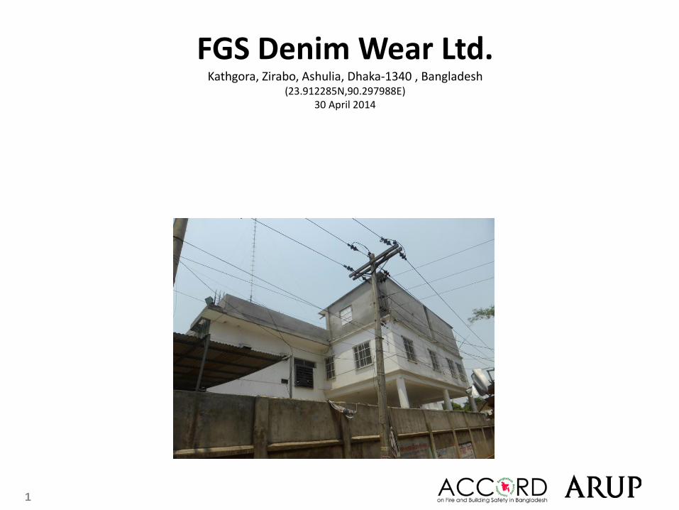
FGS Denim Wear Ltd. Kathgora, Zirabo, Ashulia, Dhaka-1340 , Bangladesh
(23.912285N,90.297988E) 30 April 2014
1
2
Observations
3
Structural design of Building 2
4 Structural design of Building 2
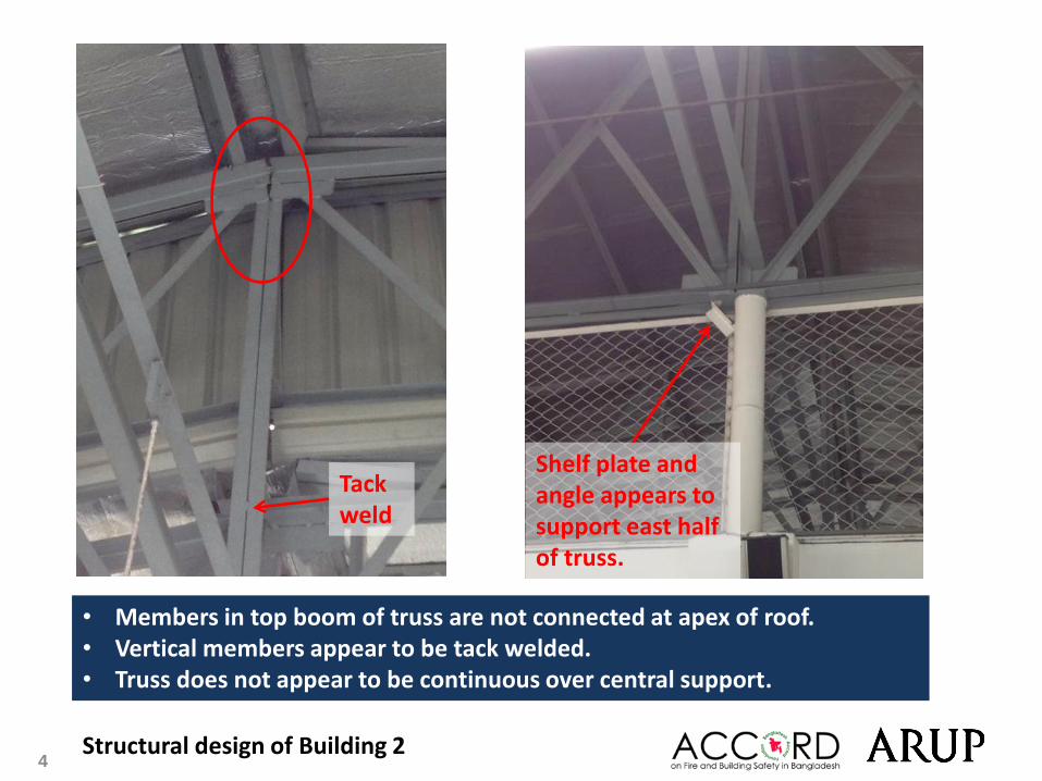
Tack weld
• Members in top boom of truss are not connected at apex of roof. • Vertical members appear to be tack welded. • Truss does not appear to be continuous over central support.
Shelf plate and angle appears to support east half of truss.
5 Structural design of Building 2
North-south
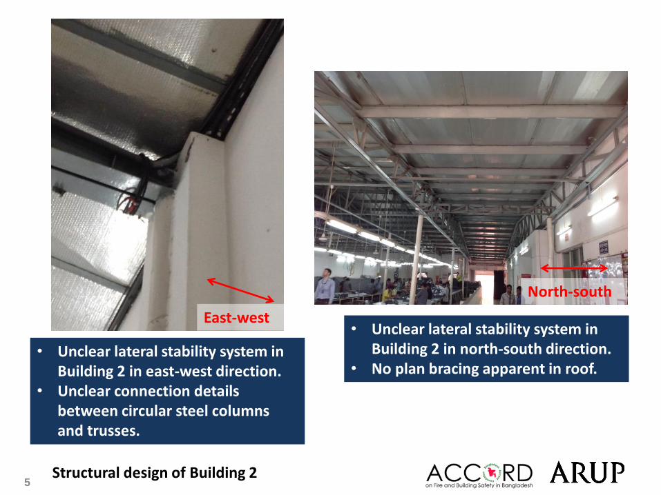
• Unclear lateral stability system in Building 2 in north-south direction.
• No plan bracing apparent in roof. • Unclear lateral stability system in
Building 2 in east-west direction. • Unclear connection details
between circular steel columns and trusses.
East-west
6 Structural design of Building 2
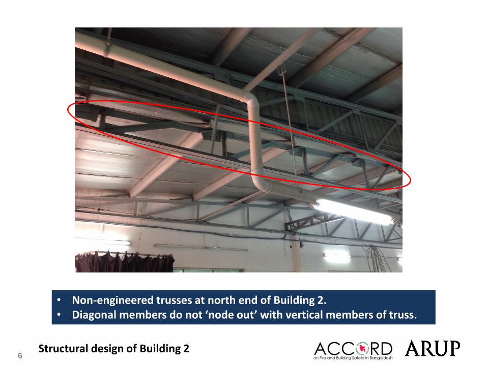
• Non-engineered trusses at north end of Building 2. • Diagonal members do not ‘node out’ with vertical members of truss.
7
Undocumented extensions to Building 1
8 Undocumented extension to Building 1
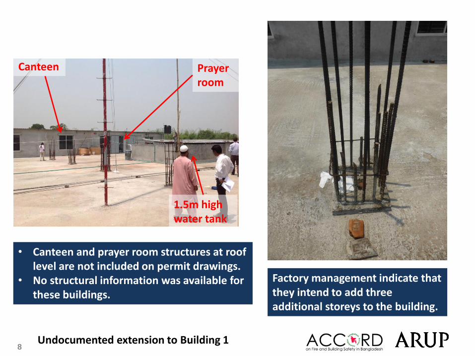
• Canteen and prayer room structures at roof level are not included on permit drawings.
• No structural information was available for these buildings.
Prayer room
Canteen
1.5m high water tank
Factory management indicate that they intend to add three additional storeys to the building.

9 Undocumented extension to Building 1
• Extension to the East of Building 1 is not included on structural drawings. Factory management indicate that this was built at the same time as Building 1.
• Different floor level observed between Building 1 and extension at 1st floor level.
Approx. 700mm difference in floor level
East extension viewed from Building 1 roof
10
Concentrated areas of high loading
11 Concentrated areas of high loading
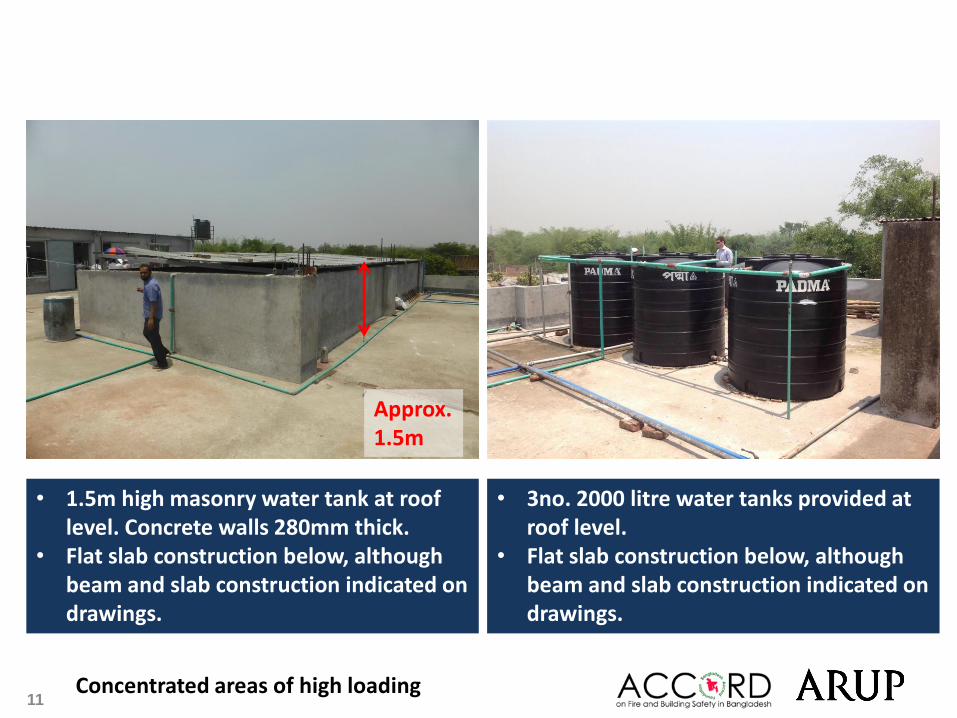
Approx. 1.5m
• 1.5m high masonry water tank at roof level. Concrete walls 280mm thick.
• Flat slab construction below, although beam and slab construction indicated on drawings.
• 3no. 2000 litre water tanks provided at roof level.
• Flat slab construction below, although beam and slab construction indicated on drawings.
12 Concentrated areas of high loading
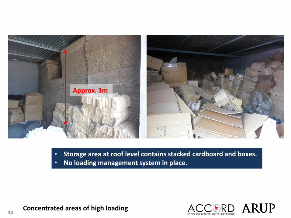
• Storage area at roof level contains stacked cardboard and boxes. • No loading management system in place.
Approx. 3m
13
Inconsistencies between structural drawings and buildings on site
14
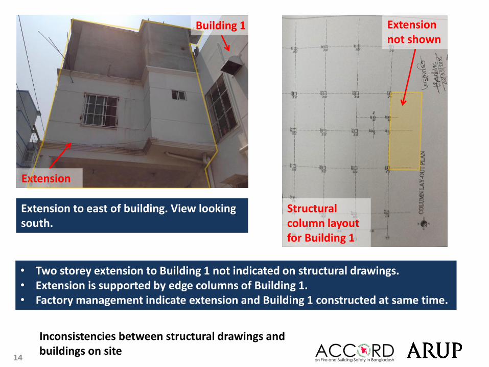
Inconsistencies between structural drawings and buildings on site
Extension
Building 1
• Two storey extension to Building 1 not indicated on structural drawings. • Extension is supported by edge columns of Building 1. • Factory management indicate extension and Building 1 constructed at same time.
Structural column layout for Building 1
Extension not shown
Extension to east of building. View looking south.
15
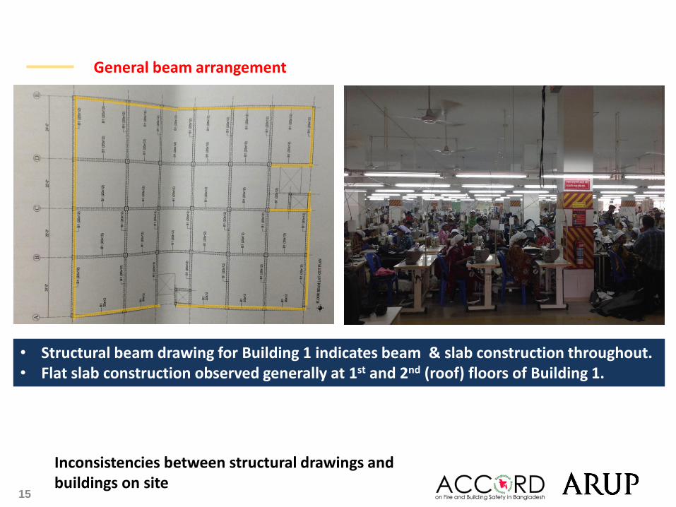
Inconsistencies between structural drawings and buildings on site
• Structural beam drawing for Building 1 indicates beam & slab construction throughout. • Flat slab construction observed generally at 1st and 2nd (roof) floors of Building 1.
General beam arrangement
16
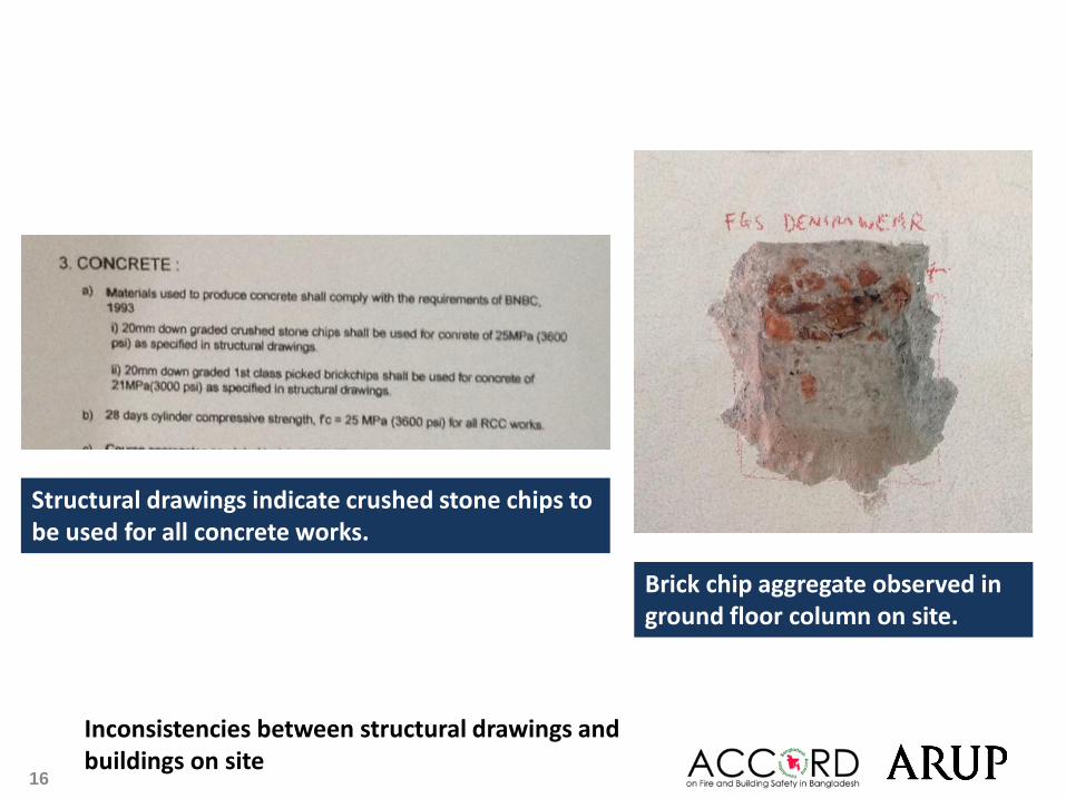
Inconsistencies between structural drawings and buildings on site
Structural drawings indicate crushed stone chips to be used for all concrete works.
Brick chip aggregate observed in ground floor column on site.
17
Evidence of cracking and damage to structural elements
18
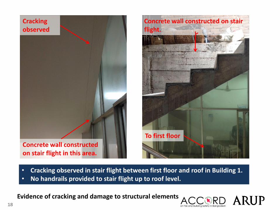
Evidence of cracking and damage to structural elements
Concrete wall constructed on stair flight.
• Cracking observed in stair flight between first floor and roof in Building 1. • No handrails provided to stair flight up to roof level.
Concrete wall constructed on stair flight in this area.
To first floor
Cracking observed

19 Evidence of cracking and damage to structural elements
• Cracks observed between masonry walls and concrete columns.
• A small number of cracks observed in slab soffits in Building 1.
• Numerous openings observed in slab and beams at corner column in Building 1.
20
Non-engineered structures
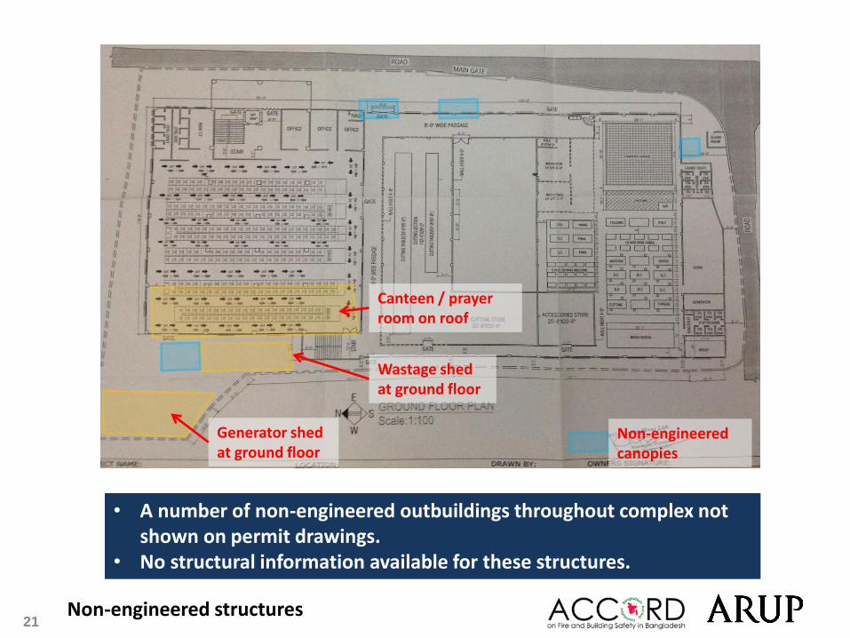
21 Non-engineered structures
• A number of non-engineered outbuildings throughout complex not shown on permit drawings.
• No structural information available for these structures.
Generator shed at ground floor
Wastage shed at ground floor
Canteen / prayer room on roof
Non-engineered canopies

22 Non-engineered structures
Non-engineered outbuildings and lean-tos throughout the complex • Structures have lightweight roofs with no plan bracing system. • Roofs susceptible to wind uplift due to inadequate holding down details.
Store to south of Building 2 Wastage shed
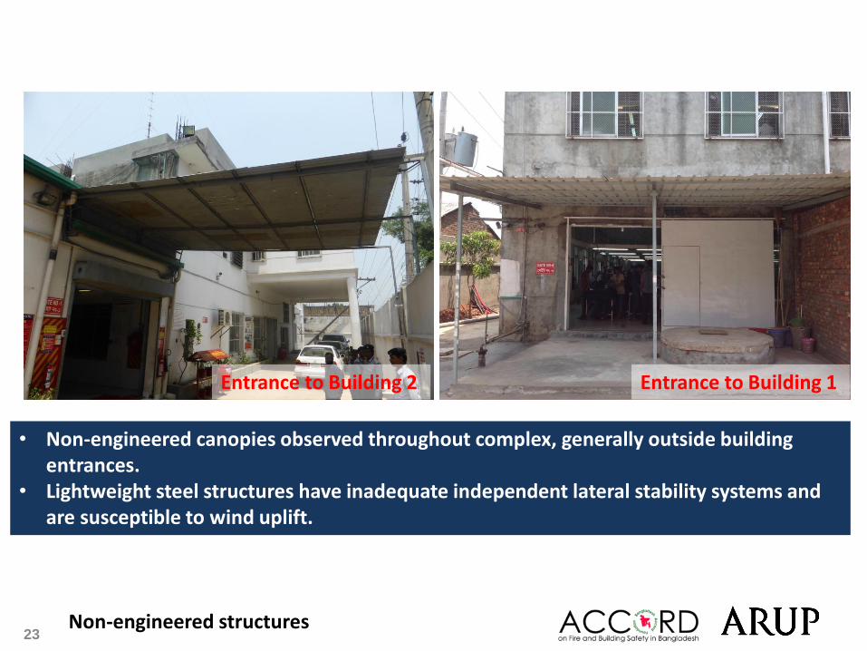
23 Non-engineered structures
• Non-engineered canopies observed throughout complex, generally outside building entrances.
• Lightweight steel structures have inadequate independent lateral stability systems and are susceptible to wind uplift.
Entrance to Building 2 Entrance to Building 1

24 Non-engineered structures
• Rooftop mast does not occur over column.
• Building Engineer to assess slab in terms of vertical and lateral loadings transmitted by mast.

25
Columns vulnerable to vehicle impact
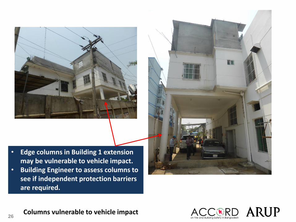
26 Columns vulnerable to vehicle impact
• Edge columns in Building 1 extension may be vulnerable to vehicle impact.
• Building Engineer to assess columns to see if independent protection barriers are required.
27
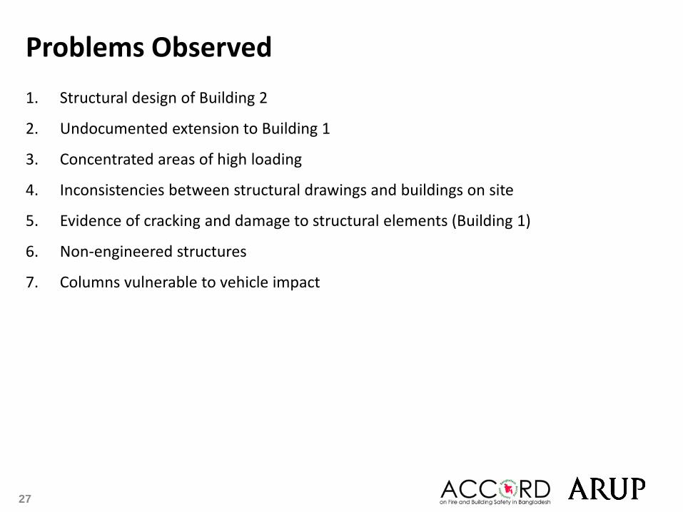
Problems Observed
1. Structural design of Building 2
2. Undocumented extension to Building 1
3. Concentrated areas of high loading
4. Inconsistencies between structural drawings and buildings on site
5. Evidence of cracking and damage to structural elements (Building 1)
6. Non-engineered structures
7. Columns vulnerable to vehicle impact

28
Item No. Observation Recommended Action Plan Recommended Timeline
1 Structural design of Building
2
Building Engineer to review the structural design of Building 2. Particular attention to be paid to i) steelwork connections and design assumptions, ii) lateral stability of the structure in north-south and east-west directions.
6-months
2 Undocumented extension to
Building 1 Supporting RC flat slabs, beams and columns to be checked for loads applied, including structures at roof level.
6-months
3 Undocumented extension to
Building 1 Check ground floor columns for buckling. 6-months
4 Undocumented extension to
Building 1 As-built structural drawings to be updated to include undocumented extensions at roof level.
6-months
5 Concentrated areas of high
loading
Building Engineer to develop loads plans for all buildings, accounting for usage, floor build-ups, solid partition walls and areas of concentrated loading.
6-months
6 Concentrated areas of high
loading
Building Engineer to verify capacity of existing roof structure (flat slab, beams and columns) to support full water tanks.
6-months
7 Concentrated areas of high
loading Factory management to implement load plans. 6-months
29
Item No. Observation Recommended Action Plan Recommended Timeline
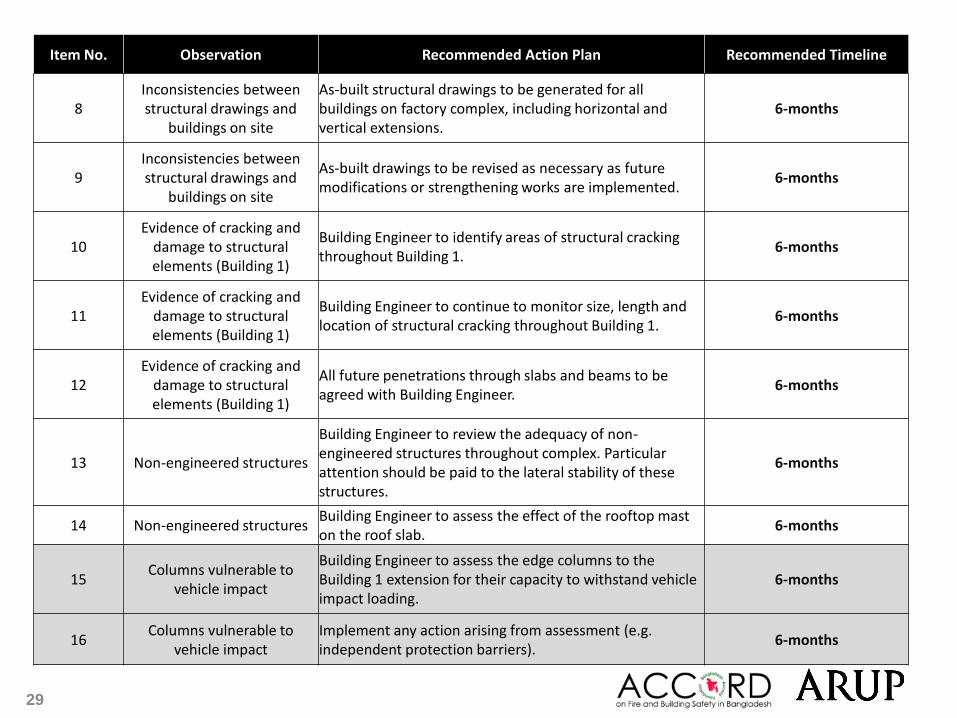
8 Inconsistencies between structural drawings and
buildings on site
As-built structural drawings to be generated for all buildings on factory complex, including horizontal and vertical extensions.
6-months
9 Inconsistencies between structural drawings and
buildings on site
As-built drawings to be revised as necessary as future modifications or strengthening works are implemented.
6-months
10 Evidence of cracking and
damage to structural elements (Building 1)
Building Engineer to identify areas of structural cracking throughout Building 1.
6-months
11 Evidence of cracking and
damage to structural elements (Building 1)
Building Engineer to continue to monitor size, length and location of structural cracking throughout Building 1.
6-months
12 Evidence of cracking and
damage to structural elements (Building 1)
All future penetrations through slabs and beams to be agreed with Building Engineer.
6-months
13 Non-engineered structures
Building Engineer to review the adequacy of non-engineered structures throughout complex. Particular attention should be paid to the lateral stability of these structures.
6-months
14 Non-engineered structures Building Engineer to assess the effect of the rooftop mast on the roof slab.
6-months
15 Columns vulnerable to
vehicle impact
Building Engineer to assess the edge columns to the Building 1 extension for their capacity to withstand vehicle impact loading.
6-months
16 Columns vulnerable to
vehicle impact Implement any action arising from assessment (e.g. independent protection barriers).
6-months