fft implementation on the tms320vc5505, · pdf filefft implementation on the tms320vc5505, ......
TRANSCRIPT

Application ReportSPRABB6B–June 2010–Revised January 2013
FFT Implementation on the TMS320VC5505,TMS320C5505, and TMS320C5515 DSPs
Mark McKeown ...............................................................................................................................
ABSTRACT
The Fast Fourier Transform (FFT) is an efficient means for computing the Discrete Fourier Transform(DFT). It is one of the most widely used computational elements in Digital Signal Processing (DSP)applications. This DSP is ideally suited for such applications. They include an FFT hardware accelerator(HWAFFT) that is tightly coupled with the CPU, allowing high FFT processing performance at very lowpower. This application report describes FFT computation on the DSP and covers the following topics:
• Basics of DFT and FFT
• DSP Overview Including the FFT Accelerator
• HWAFFT Description
• HWAFFT Software Interface
• Simple Example to Illustrate the Use of the FFT Accelerator
• FFT Benchmarks
• Description of Open Source FFT Example Software
• Computation of Large (Greater Than 1024-point) FFTs
Project collateral and source code discussed in this application report can be downloaded from thefollowing URL: http://www-s.ti.com/sc/techlit/sprabb6.zip.
Contents1 Basics of DFT and FFT .................................................................................................... 22 DSP Overview Including the FFT Accelerator .......................................................................... 63 FFT Hardware Accelerator Description .................................................................................. 84 HWAFFT Software Interface ............................................................................................. 115 Simple Example to Illustrate the Use of the FFT Accelerator ....................................................... 176 FFT Benchmarks .......................................................................................................... 207 Description of Open Source FFT Example Software ................................................................. 218 Computation of Large (Greater Than 1024-Point) FFTs ............................................................. 229 Appendix A Methods for Aligning the Bit-Reverse Destination Vector ............................................. 25Appendix A Revision History .................................................................................................. 27
List of Figures
1 DIT Radix 2 Butterfly ....................................................................................................... 3
2 DIT Radix 2 8-point FFT ................................................................................................... 4
3 Graphical FFT Computation ............................................................................................... 5
4 Block Diagram ............................................................................................................... 7
5 Bit Reversed Input Buffer................................................................................................. 13
6 Graphing the Real Part of the FFT Result in CCS4 .................................................................. 19
7 Graphing the Imaginary Part of the FFT Result in CCS4 ............................................................ 19
8 FFT Filter Demo Block Diagram......................................................................................... 21
List of Tables
1SPRABB6B–June 2010–Revised January 2013 FFT Implementation on the TMS320VC5505, TMS320C5505, andTMS320C5515 DSPsSubmit Documentation Feedback
Copyright © 2010–2013, Texas Instruments Incorporated
/ 2-11( ) (2 1) , 0 - 1
( / 2) / 20
Nnk
X k x n W k to NNodd Nn
= + =å
=
/ 2-11( ) (2 ) , 0 - 1
( / 2) / 20
Nnk
X k x n W k to NNeven Nn
= =å
=
( )X k
even
( )X k
odd
/ 2-1 / 2-11( ) (2 ) (2 1) , 0 - 1
/ 2 / 20 0
kWN N
nk nkNX k x n W x n W k to N
N NN Nn n
= + + =å å
= =
/ 2- 2 / - 2 /( / 2)2 2( ) ( ) - , 0 / 2 - 1/ 2
k Nj N j Nnk nk nk nk kW e e W and W W k to NN N N N
+P P= = = = =
/ 2-1 / 2-11 2 2( ) (2 ) (2 1) , 0 - 10 0
kWN N
nk nkNX k x n W x n W k to N
N NN Nn n
= + + =å å
= =
kW
N
/ 2-1 / 2-1 (2 1)1 12( ) (2 ) (2 1) , 0 - 10 0
N N n knkX k x n W x n W k to N
N NN Nn n
+= + + =å å
= =
- 2 /, 0 - 1
j NW e k to N
N
p
= =
-11( ) ( ) , 0 - 1
0
Nnk
X k x n W k to NN Nn
= =å
=
Basics of DFT and FFT www.ti.com
1 Computational Complexity of Direct DFT Computation versus Radix-2 FFT ....................................... 4
2 Available HWAFFT Routines ............................................................................................ 15
3 FFT Performance on HWAFFT vs CPU (Vcore = 1.05 V, PLL = 60 MHz) ........................................ 20
4 FFT Performance on HWAFFT vs CPU (Vcore = 1.3 V, PLL = 100 MHz) ........................................ 20
5 Revision History ........................................................................................................... 27
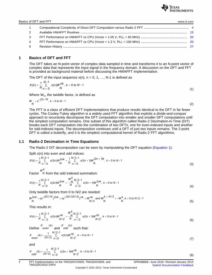
1 Basics of DFT and FFT
The DFT takes an N-point vector of complex data sampled in time and transforms it to an N-point vector ofcomplex data that represents the input signal in the frequency domain. A discussion on the DFT and FFTis provided as background material before discussing the HWAFFT implementation.
The DFT of the input sequence x(n), n = 0, 1, …, N-1 is defined as
(1)
Where WN, the twiddle factor, is defined as
(2)
The FFT is a class of efficient DFT implementations that produce results identical to the DFT in far fewercycles. The Cooley-Tukey algorithm is a widely used FFT algorithm that exploits a divide-and-conquerapproach to recursively decompose the DFT computation into smaller and smaller DFT computations untilthe simplest computation remains. One subset of this algorithm called Radix-2 Decimation-in-Time (DIT)breaks each DFT computation into the combination of two DFTs, one for even-indexed inputs and anotherfor odd-indexed inputs. The decomposition continues until a DFT of just two inputs remains. The 2-pointDFT is called a butterfly, and it is the simplest computational kernel of Radix-2 FFT algorithms.
1.1 Radix-2 Decimation in Time Equations
The Radix-2 DIT decomposition can be seen by manipulating the DFT equation (Equation 1):
Split x(n) into even and odd indices:
(3)
Factor from the odd indexed summation:
(4)
Only twiddle factors from 0 to N/2 are needed:
(5)
This results in:
(6)
Define and such that:
(7)
and
(8)
2 FFT Implementation on the TMS320VC5505, TMS320C5505, and SPRABB6B–June 2010–Revised January 2013TMS320C5515 DSPs Submit Documentation Feedback
Copyright © 2010–2013, Texas Instruments Incorporated

P
QQ’ = P – Q
k
NW*
P’ = P + Qk
NW*
k
NW
+
+
+
–
kW
N
1( / 2) ( ( ) - ( )), 0 / 2 - 1
2
kX k N X k W X k k to N
even N odd
+ = =
1( ) ( ( ) ( )), 0 / 2 - 1
2
kX k X k W X k k to N
even N odd
= + =
www.ti.com Basics of DFT and FFT
Finally, Equation 6 is rewritten as:
(9)
and
(10)
Equation 9 and Equation 10 show that the N-point DFT can be divided into two smaller N/2-point DFTs.Each smaller DFT is then further divided into smaller DFTs until N = 2. The pair of equations that makeupthe 2-point DFT is called the Radix2 DIT Butterfly (see Section 1.2). The DIT Butterfly is the corecalculation of the FFT and consists of just one complex multiplication and two complex additions.
1.2 Radix-2 DIT Butterfly
The Radix-2 Butterfly is illustrated in Figure 1. In each butterfly structure, two complex inputs P and Q areoperated upon and become complex outputs P’ and Q’. Complex multiplication is performed on Q and thetwiddle factor, then the product is added to and subtracted from input P to form outputs P’ and Q’. The
exponent of the twiddle factor is dependent on the stage and group of its butterfly. The butterfly isusually represented by its flow graph (Figure 1), which looks like a butterfly.
Figure 1. DIT Radix 2 Butterfly
The mathematical meaning of this butterfly is shown below with separate equations for real and imaginaryparts:
Complex Real Part Imaginary Part
P’ = P + Q * W Pr’ = Pr + (Qr * Wr - Qi * Wi) Pi’ = Pi + (Qr * Wi + Qi * Wr)
Q’ = P - Q * W Qr’ = Pr - (Qr * Wr - Qi * Wi) Qi’ = Pi - (Qr * Wi + Qi * Wr)
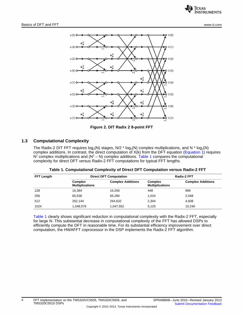
The flow graph in Figure 2 shows the interconnected butterflies of an 8-point Radix-2 DIT FFT. Notice thatthe inputs to the FFT are indexed in bit-reversed order (0, 4, 2, 6, 1, 5, 3, 7) and the outputs are indexedin sequential order (0, 1, 2, 3, 4, 5, 6, 7). Computation of a Radix-2 DIT FFT requires the input vector to bein bit-reversed order, and generates an output vector in sequential order. This bit-reversal is furtherexplained in Section 4.3, Bit-Reverse Function.
3SPRABB6B–June 2010–Revised January 2013 FFT Implementation on the TMS320VC5505, TMS320C5505, andTMS320C5515 DSPsSubmit Documentation Feedback
Copyright © 2010–2013, Texas Instruments Incorporated
Basics of DFT and FFT www.ti.com
Figure 2. DIT Radix 2 8-point FFT
1.3 Computational Complexity
The Radix-2 DIT FFT requires log2(N) stages, N/2 * log2(N) complex multiplications, and N * log2(N)complex additions. In contrast, the direct computation of X(k) from the DFT equation (Equation 1) requiresN2 complex multiplications and (N2 – N) complex additions. Table 1 compares the computationalcomplexity for direct DFT versus Radix-2 FFT computations for typical FFT lengths.
Table 1. Computational Complexity of Direct DFT Computation versus Radix-2 FFT
FFT Length Direct DFT Computation Radix-2 FFT
Complex Complex Additions Complex Complex AdditionsMultiplications Multiplications
128 16,384 16,256 448 896
256 65,536 65,280 1,024 2,048
512 262,144 264,632 2,304 4,608
1024 1,048,576 1,047,552 5,120 10,240
Table 1 clearly shows significant reduction in computational complexity with the Radix-2 FFT, especiallyfor large N. This substantial decrease in computational complexity of the FFT has allowed DSPs toefficiently compute the DFT in reasonable time. For its substantial efficiency improvement over directcomputation, the HWAFFT coprocessor in the DSP implements the Radix-2 FFT algorithm.
4 FFT Implementation on the TMS320VC5505, TMS320C5505, and SPRABB6B–June 2010–Revised January 2013TMS320C5515 DSPs Submit Documentation Feedback
Copyright © 2010–2013, Texas Instruments Incorporated
Real (Time Domain Signal) Real (Frequency Domain Signal)
Imaginary (Time Domain Signal) Imaginary (Frequency Domain Signal)
FFT
IFFT
www.ti.com Basics of DFT and FFT
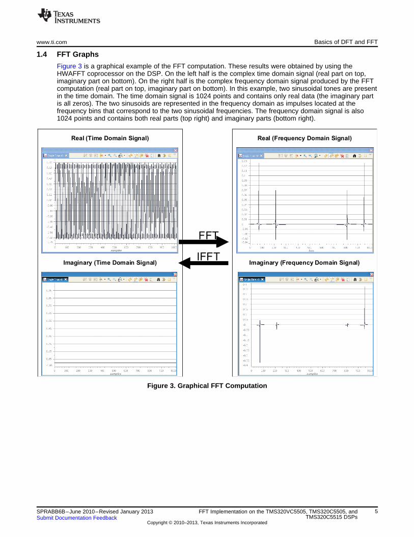
1.4 FFT Graphs
Figure 3 is a graphical example of the FFT computation. These results were obtained by using theHWAFFT coprocessor on the DSP. On the left half is the complex time domain signal (real part on top,imaginary part on bottom). On the right half is the complex frequency domain signal produced by the FFTcomputation (real part on top, imaginary part on bottom). In this example, two sinusoidal tones are presentin the time domain. The time domain signal is 1024 points and contains only real data (the imaginary partis all zeros). The two sinusoids are represented in the frequency domain as impulses located at thefrequency bins that correspond to the two sinusoidal frequencies. The frequency domain signal is also1024 points and contains both real parts (top right) and imaginary parts (bottom right).
Figure 3. Graphical FFT Computation
5SPRABB6B–June 2010–Revised January 2013 FFT Implementation on the TMS320VC5505, TMS320C5505, andTMS320C5515 DSPsSubmit Documentation Feedback
Copyright © 2010–2013, Texas Instruments Incorporated

DSP Overview Including the FFT Accelerator www.ti.com
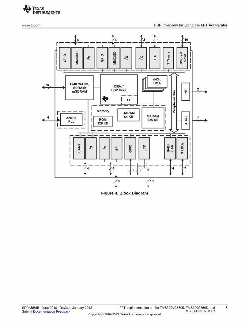
2 DSP Overview Including the FFT Accelerator
This DSP is a member of TI's TMS320C5000™ fixed-point DSP product family and is designed for low-power applications. With an active mode power consumption of less than 0.15 mW/MHz and a standbymode power consumption of less than 0.15 mW, these DSPs are optimized for applications characterizedby sophisticated processing and portable form factors that require low power and longer battery life.Examples of such applications include portable voice/audio devices, noise cancellation headphones,software-defined radio, musical instruments, medical monitoring devices, wireless microphones,biometrics, industrial instruments, telephony, and audio cards.
Figure 4 shows an overview of the DSP consisting of the following primary components:
• Dual MAC, C55x CPU
1.05 V @ 60 MHz (VC5505, C5505, C5515) and 75 MHz (C5505 and C5515)
1.3 V @ 100 MHz (VC5505, C5505, C5515) and 120 MHz (C5505 and C5515)
1.4 V @ 150 MHz (C5505)
• On-Chip memory: 320 KB RAM (64 KB DARAM, 256 KB SARAM), 128 KB ROM
• HWAFFT that supports 8- to 1024-point (powers of 2) real and complex-valued FFTs
• Four DMA controllers and external memory interface
• Power management module
• A set of I/O peripherals that includes I2C, I2S, SPI, UART, Timers, EMIF, MMC/SD, GPIO, 10-bit SAR,LCD Controller, USB 2.0
• Three on-chip LDO Regulators (C5515), 1 on-chip LDO Regulator (VC5505, C5505)
• SDRAM/mSDRAM support (C5505 and C5515)
6 FFT Implementation on the TMS320VC5505, TMS320C5505, and SPRABB6B–June 2010–Revised January 2013TMS320C5515 DSPs Submit Documentation Feedback
Copyright © 2010–2013, Texas Instruments Incorporated
Pe
rip
he
ra
lB
u
6
GP
IO
MM
C/S
D
IS
2
6
GP
IO
MM
C/S
D
IS
2
2 4 16
IC
2
RT
C
3 T
imers
US
B 2
.0sla
ve
EMIF/NAND,SDRAM/
mSDRAM
60
4
INT
UA
RT
IS
2 SP
I32KHz
PLLROM
128 KB
MemoryDARAM64 KB SARAM
256 KB
JTA
G
2
7
IS
2
4-Ch.DMA
C55xDSP Core
TM
FFT
GP
IO
LC
D
4 4
8
8
13
810-B
itS
AR
4
3 L
DO
s
7
Peri
ph
era
l B
us
www.ti.com DSP Overview Including the FFT Accelerator
Figure 4. Block Diagram
7SPRABB6B–June 2010–Revised January 2013 FFT Implementation on the TMS320VC5505, TMS320C5505, andTMS320C5515 DSPsSubmit Documentation Feedback
Copyright © 2010–2013, Texas Instruments Incorporated

FFT Hardware Accelerator Description www.ti.com
The C55x CPU includes a tightly coupled FFT accelerator that communicates with the C55x CPU throughthe use of the coprocessor instructions. The main features of this hardware accelerator are:
• Supports 8- to 1024-point (powers of 2) complex-valued FFTs.
• Internal twiddle factor generation for optimal use of memory bandwidth and more efficientprogramming.
• Basic and software-driven auto-scaling feature provides good precision versus cycle count trade-off.
• Single-stage and double-stage modes enable computation of one or two stages in one pass, and thusbetter handle the odd power of two FFT widths.
• Is 4 to 6 times more energy efficient and 2.2 to 3.8 times faster than the FFT computations on theCPU.
3 FFT Hardware Accelerator Description
The HWAFFT in the DSP is a tightly-coupled, software-controlled coprocessor designed to perform FFTand inverse FFT (IFFT) computations on complex data vectors ranging in length from 8 to 1024 points(powers of 2). It implements a Radix-2 DIT structure that returns the FFT or IFFT result in bit-reversedorder.
3.1 Tightly-Coupled Hardware Accelerator
The HWAFFT is tightly-coupled with the DSP core which means that it is physically located outside of theDSP core but has access to the core’s full memory read bandwidth (busses B, C, and D), access to thecore’s internal registers and accumulators, and access to its address generation units. The HWAFFTcannot access the data write busses or memory mapped registers (MMRs). Because the HWAFFT is seenas part of the execution unit of the CPU, it must also comply to the core’s pipeline exceptions, and inparticular those caused by stalls and conditional execution.
3.2 Hardware Butterfly, Double-Stage and Single-Stage Mode
The core of the HWAFFT consists of a single Radix-2 DIT Butterfly implemented in hardware. Thishardware supports a double-stage mode where two FFT stages are computed a single pass. In this modethe HWAFFT feeds the results from the first stage back into the hardware butterfly to compute the secondstage results in a single pass. This double-stage mode offers significant speed-up especially for large FFTlengths. However, when the number of required stages is odd (FFT lengths = 8, 32, 128, or 512 points)the final stage needs to be computed alone and, consequently, at a lower acceleration rate. For thisreason a single-stage mode is also provided.
The HWAFFT supports two stage modes:
• Double-Stage Mode – two FFT stages performed in each pass
• Single-Stage Mode – one FFT stage performed in each pass
3.3 Pipeline and Latency
The logic of the HWAFFT is pipelined to deliver maximum throughput. Complex multiplication with thetwiddle factors is performed in the first pipeline stage, and complex addition and subtraction is performedin the second pipeline stage. Valid results appear some cycles of latency after the first data is read frommemory:
• 5 cycles of latency in single-stage mode
• 9 cycles of latency in double-stage mode
There are three states to consider during computation of a single or double stage:
• Prologue: The hardware accelerator is fed with one complex input at a time but does not output anyvalid data.
• Kernel: Valid outputs appear while new inputs are received and computed upon.
• Epilogue: A few more cycles are needed to flush the pipeline and output the last butterfly results.
8 FFT Implementation on the TMS320VC5505, TMS320C5505, and SPRABB6B–June 2010–Revised January 2013TMS320C5515 DSPs Submit Documentation Feedback
Copyright © 2010–2013, Texas Instruments Incorporated
www.ti.com FFT Hardware Accelerator Description
Consecutive stages can be overlapped such that the first data points for the next pass are read while thefinal output values of the current pass are returned. For odd-power-of-two FFT lengths, the last double-stage pass needs to be completed before starting a final single-stage pass. Thus, the double-stagelatency is only experienced once for even-powers-of-2 FFT computations and twice for odd-powers-of-2FFT computations. Latency has little impact on the total computation performance, and less and less soas the FFT size increases.
3.4 Software Control
Software is required to communicate between the CPU and the HWAFFT. The CPU instruction setarchitecture (ISA) includes a class of coprocessor (copr) instructions that allows the CPU to initialize, passdata to, and execute butterfly computations on the HWAFFT. Computation of an FFT/IFFT is performed byexecuting a sequence of these copr instructions.
C-callable HWAFFT functions are provided with optimized sequences of copr instructions for eachavailable FFT length. To conserve program memory, these functions are located in the DSP’s ROM. Adetailed explanation of the HWAFFT software interface and its application is provided in Section 4,HWAFFT Software Interface.
NOTE: To execute the HWAFFT routines from the ROM of the DSP, the programmer must satisfymemory allocation restrictions for the data and scratch buffers. See the device-specific erratafor an explanation of the restrictions and workarounds:
• TMS320VC5505/VC5504 Fixed-Point DSP Silicon Errata (Silicon Revision 1.4)[literature number SPRZ281]
• TMS320C5505/C5504 Fixed-Point DSP Silicon Errata (Silicon Revision 2.0)[literature number SPRZ310]
• TMS320C5515/C5514 Fixed-Point DSP Silicon Errata (Silicon Revision 2.0)[literature number SPRZ308]
3.5 Twiddle Factors
To conserve memory bus bandwidth, twiddle factors are stored in a look-up-table within the HWAFFTcoprocessor. The 512 complex twiddle factors (16-bit real, 16-bit imaginary) are available for computing upto 1024-point FFTs. Smaller FFT lengths use a decimated subset of these twiddle factors. Indexing thetwiddle table is pipelined and optimized based on the current FFT stage and group being computed. Whenthe IFFT computation is performed, the complex conjugates of the twiddle factors are used.
9SPRABB6B–June 2010–Revised January 2013 FFT Implementation on the TMS320VC5505, TMS320C5505, andTMS320C5515 DSPsSubmit Documentation Feedback
Copyright © 2010–2013, Texas Instruments Incorporated

FFT Hardware Accelerator Description www.ti.com
3.6 Scaling
FFT computation with fixed-point numbers is vulnerable to overflow, underflow, and saturation effects.Depending on the dynamic range of the input data, some scaling may be required to avoid these effectsduring the FFT computation. This scaling can be done before the FFT computation, by computing thedynamic range of the input points and scaling them down accordingly. If the magnitude of each complexinput element is less than 1/N, where N = FFT Length, then the N-point FFT computation will not overflow.
Uniformly dividing the input vector elements by N (Pre-scaling) is equivalent to shifting each binarynumber right by log2(N) bits, which introduces significant error (especially for large FFT lengths). Whenthis error propagates through the FFT flow graph, the output noise-to-signal ratio increases by 1 bit perstage or log2(N) bits in total. Overflow will not occur if each input’s magnitude is less than 1/N.
Alternatively, a simple divide-by-2 and round scaling after each butterfly offers a good trade-off betweenprecision and overflow protection, while minimizing computation cycles. Because the error introduced byearly FFT stages is also scaled after each butterfly, the output noise-to-signal ratio increases by just ½ bitper stage or ½ * log2(N) bits in total. Overflow is avoided if each input’s magnitude is less than 1.
The HWAFFT supports two scale modes:
• NOSCALE
– Scaling logic disabled
– Vulnerable to overflow
– Output dynamic range grows with each stage
– No overflow if input magnitudes < 1/N
• SCALE
– Scales each butterfly output by 1/2
– No overflow if input magnitudes < 1
10 FFT Implementation on the TMS320VC5505, TMS320C5505, and SPRABB6B–June 2010–Revised January 2013TMS320C5515 DSPs Submit Documentation Feedback
Copyright © 2010–2013, Texas Instruments Incorporated
Int32 CMPLX_Vec32[N] = …(N = FFT Length)
Real[0] Imag[0] Real[1] Imag[1] Imag[2]Real[2]
Bit31,.................., Bit16, Bit15,.................., Bit0 Bit31,.................., Bit16, Bit15,.................., Bit0 Bit31,.................., Bit16, Bit15,.................., Bit0
Int16 CMPLX_Vec16[2*N] = …(N = FFT Length)
Real[0] Imag[0] Real[1] Imag[1] Imag[2]Real[2]
Bit15,..................,Bit0Bit15,..................,Bit0 Bit15,..................,Bit0 Bit15,..................,Bit0 Bit15,..................,Bit0 Bit15,..................,Bit0
www.ti.com HWAFFT Software Interface
4 HWAFFT Software Interface
The software interface to the HWAFFT is handled through a set of coprocessor instructions that, whendecoded by the coprocessor, perform initialization, load/store, and execution operations on the HWAFFTcoprocessor. C-callable functions are provided that contain the necessary sequences of coprocessorinstructions for performing FFT/ IFFT computations in the range of 8 to 1024 points (by powers of 2).Additionally, an optimized out-of-place bit-reversal function is provided to perform the complex vector bit-reversal required by Radix-2 FFT computations. These functions are defined in the hwafft.asm sourcecode file. Additionally, to conserve on-chip RAM these functions have been placed in the on-chip ROM ofthe DSP. See Section 4.5, Project Configuration for Calling Function s from ROM, for steps to configureyour project to call the HWAFFT functions from ROM.
4.1 Data Types
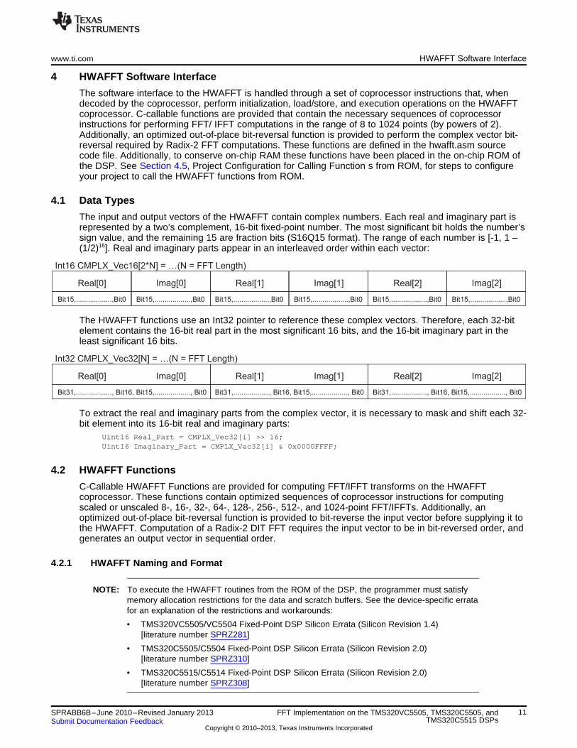
The input and output vectors of the HWAFFT contain complex numbers. Each real and imaginary part isrepresented by a two’s complement, 16-bit fixed-point number. The most significant bit holds the number’ssign value, and the remaining 15 are fraction bits (S16Q15 format). The range of each number is [-1, 1 –(1/2)15]. Real and imaginary parts appear in an interleaved order within each vector:
The HWAFFT functions use an Int32 pointer to reference these complex vectors. Therefore, each 32-bitelement contains the 16-bit real part in the most significant 16 bits, and the 16-bit imaginary part in theleast significant 16 bits.
To extract the real and imaginary parts from the complex vector, it is necessary to mask and shift each 32-bit element into its 16-bit real and imaginary parts:
Uint16 Real_Part = CMPLX_Vec32[i] >> 16;Uint16 Imaginary_Part = CMPLX_Vec32[i] & 0x0000FFFF;
4.2 HWAFFT Functions
C-Callable HWAFFT Functions are provided for computing FFT/IFFT transforms on the HWAFFTcoprocessor. These functions contain optimized sequences of coprocessor instructions for computingscaled or unscaled 8-, 16-, 32-, 64-, 128-, 256-, 512-, and 1024-point FFT/IFFTs. Additionally, anoptimized out-of-place bit-reversal function is provided to bit-reverse the input vector before supplying it tothe HWAFFT. Computation of a Radix-2 DIT FFT requires the input vector to be in bit-reversed order, andgenerates an output vector in sequential order.
4.2.1 HWAFFT Naming and Format
NOTE: To execute the HWAFFT routines from the ROM of the DSP, the programmer must satisfymemory allocation restrictions for the data and scratch buffers. See the device-specific erratafor an explanation of the restrictions and workarounds:
• TMS320VC5505/VC5504 Fixed-Point DSP Silicon Errata (Silicon Revision 1.4)[literature number SPRZ281]
• TMS320C5505/C5504 Fixed-Point DSP Silicon Errata (Silicon Revision 2.0)[literature number SPRZ310]
• TMS320C5515/C5514 Fixed-Point DSP Silicon Errata (Silicon Revision 2.0)[literature number SPRZ308]
11SPRABB6B–June 2010–Revised January 2013 FFT Implementation on the TMS320VC5505, TMS320C5505, andTMS320C5515 DSPsSubmit Documentation Feedback
Copyright © 2010–2013, Texas Instruments Incorporated
HWAFFT Software Interface www.ti.com
The HWAFFT functions are named hwafft_Npts, where N is the FFT length. For example, hwafft_32pts isthe name of the function for performing 32-point FFT and IFFT operations. The structure of the HWAFFTfunctions is:Uint16 hwafft_Npts( Performs N-point complex FFT/IFFT, where N = {8, 16, 32, 64, 128, 256, 512,
1024}Int32 *data, Input/output – complex vectorInt32 *scratch, Intermediate/output – complex vectorUint16 Flag determines whether FFT or IFFT performed, (0 = FFT, 1 = IFFT)
fft_flag,
Uint16 Flag determines whether butterfly output divided by 2 (0 = Scale, 1 = No Scale)scale_flag
); Return value Flag determines whether output in data or scratch vector (0 = data, 1 = scratch)
4.2.2 HWAFFT Parameters
The following describe the parameters for the HWAFFT functions.
Int32 *data
This is the input vector to the HWAFFT. It contains complex data elements (real part in most significant 16bits, imaginary part in least significant 16 bits). After the HWAFFT function completes, the result will eitherbe stored in this data vector or in the scratch vector, depending on the status of the return value. Thereturn value is Boolean where 0 indicates that the result is stored in this data vector, and 1 indicates thescratch vector. The data and scratch vectors must reside in separate blocks of RAM (DARAM or SARAM)to maximize memory bandwidth.#pragma DATA_SECTION(data_buf, "data_buf");
//Static Allocation to Section: "data_buf : > DARAM" in Linker CMD FileInt32 data_buf[N = FFT Length];Int32 *data = data_buf;Int32 *data:
The *data parameter is a complex input vector to HWAFFT. It contains the output vector if Return Value =0 = OUT_SEL_DATA. There is a strict address alignment requirement if *data is shared with a bit-reversedestination vector (recommended). See Section 4.3.1, Bit Reverse Destination Vector AlignmentRequirement.
Int32 *scratch
This is the scratch vector used by the HWAFFT to store intermediate results between FFT stages. Itcontains complex data elements (real part in most significant 16 bits, imaginary part in least significant 16bits). After the HWAFFT function completes the result will either be stored in the data vector or in thisscratch vector, depending on the status of the return value. The return value is Boolean, where 0 indicatesthat the result is stored in the data vector, and 1 indicates this scratch vector. The data and scratchvectors must reside in separate blocks of RAM (DARAM or SARAM) to maximize memory bandwidth.#pragma DATA_SECTION(scratch_buf, "scratch_buf");
//Static Allocation to Section: "scratch_buf : > DARAM" in Linker CMD FileInt32 scratch_buf[N = FFT Length];Int32 *scratch = scratch_buf;Int32 *scratch:
The *scratch parameter is a complex scratchpad vector to HWAFFT. It contains the output vector if ReturnValue = 1 = OUT_SEL_SCRATCH.
Uint16 fft_flag
The FFT/IFFT selection is controlled by setting the fft_flag to 0 for FFT and 1 for Inverse FFT.#define FFT_FLAG ( 0 ) /* HWAFFT to perform FFT */#define IFFT_FLAG ( 1 ) /* HWAFFT to perform IFFT */Uint16 fft_flag:
12 FFT Implementation on the TMS320VC5505, TMS320C5505, and SPRABB6B–June 2010–Revised January 2013TMS320C5515 DSPs Submit Documentation Feedback
Copyright © 2010–2013, Texas Instruments Incorporated

Int32 data[8]
Int32 data_br[8]
Data[0] Data[1] Data[2] Data[3] Data[4] Data[5] Data[6] Data[7]
Data[0] Data[1] Data[2] Data[3] Data[4] Data[5] Data[6] Data[7]
Index = 000 001 010 011 100 101 110 111
Index = 000 100 010 110 001 101 011 111
www.ti.com HWAFFT Software Interface
fft_flag = FFT_FLAG: FFT Performedfft_flag = IFFT_FLAG: Inverse FFT Performed
Uint16 scale_flag
The automatic scaling (divide each butterfly output by 2) feature is controlled by setting the scale_flag to 0to enable scaling and 1 to disable scaling.#define SCALE_FLAG ( 0 ) /* HWAFFT to scale butterfly output */#define NOSCALE_FLAG ( 1 ) /* HWAFFT not to scale butterfly output */Uint16 scale_flag:
scale_flag = SCALE_FLAG: Divide by 2 scaling is performed at the output of each FFT Butterfly.scale_flag = NOSCALE_FLAG: No scaling is performed, overflow may occur if the input dynamic is
too high.
Uint16 <Return Value>:
This is the Uint16 return value of the HWAFFT functions. After the HWAFFT function completes, the resultwill either be stored in the data vector or in the scratch vector, depending on the status of this returnvalue. The return value is Boolean where 0 indicates that the result is stored in the data vector, and 1indicates this scratch vector. The program must check the status of the Return Value to determine thelocation of the FFT/IFFT result.#define OUT_SEL_DATA ( 0 ) /* indicates HWAFFT output located in input data vector */#define OUT_SEL_SCRATCH ( 1 ) /* indicates HWAFFT output located in scratch vector */Uint16 <Return Value>:
Return Value = OUT_SEL_DATA: FFT/IFFT result located in the data vectorReturn Value = OUT_SEL_SCRATCH: FFT/IFFT result located in the scratch vector
4.3 Bit Reverse Function
Before computing the FFT/IFFT on the HWAFFT, the input buffer must be bit-reversed to facilitate aRadix-2 DIT computation. This function contains optimized assembly that executes on the CPU torearrange the Int32 elements of the input vector by placing each element in the destination vector at theindex that corresponds to the bit-reversal of its current index. For example, in an 8-element vector, theindex of the third element is 011 in binary, then the bit-reversed index is 110 in binary or 6 in decimal, sothe third element of the input vector is copied to the sixth element of the bit-reversal destination vector.
Figure 5. Bit Reversed Input Buffer
13SPRABB6B–June 2010–Revised January 2013 FFT Implementation on the TMS320VC5505, TMS320C5505, andTMS320C5515 DSPsSubmit Documentation Feedback
Copyright © 2010–2013, Texas Instruments Incorporated
HWAFFT Software Interface www.ti.com
4.3.1 Bit Reverse Destination Vector Alignment Requirement
Strict requirements are placed on the address of the bit-reversal destination buffer. This buffer must bealigned in RAM such that log2(4 * N) zeros appear in the least significant bits of the byte address (8 bits),where N is the FFT Length. For example, a 1024-point FFT needs to bit-reverse 1024 complex arrayelements (32-bit elements). The address for the bit-reversed buffer needs to have 12 zeros in the leastsignificant bits of its byte address (log2(4 * 1024) = 12). Since the word address (16 bits) is the byteaddress shifted right one bit, the word address requires 11 zeros in the least significant bits. This bit-reverse is considered out-of-place because the inputs and outputs are stored in different vectors. In-placebit-reversal is not supported by this function. There are no alignment requirements for the bit-reversesource vector.
4.3.2 Bit Reverse Format and Parameters
The structure of the HWAFFT functions is:
void hwafft_br( Performs out-of-place bit-reversal on 32-bit data vectorInt32 *data, Input – 32-bit data vectorInt32 Output – bit-reversed data vector
*data_br,
Uint16 Length of complex data vectordata_len,
);
The parameters for the hwafft_br function are:
Int32 *data
This is the input vector to the bit reverse function. It contains complex data elements (real part in mostsignificant 16 bits, imaginary part in least significant 16 bits). There are no specific alignment requirementsfor this vector.#pragma DATA_SECTION(data_buf, "data_buf");
//Static Allocation to Section: "data_buf : > DARAM" in Linker CMD FileInt32 data_buf[N = FFT Length];Int32 *data = data_buf;
Int32 *data_br
This is the destination vector of the bit-reverse function. It contains complex data elements (real part inmost significant 16 bits, imaginary part in least significant 16 bits). A strict alignment requirement is placedon this destination vector of the bit-reverse function: This buffer must be aligned in RAM such that log2(4 *N) zeros appear in the least significant bits of the byte address (8 bits), where N is the FFT Length. SeeSection 9, Appendix A Methods for Aligning the Bit-Reverse Destination Vector, for ways to force thelinker to enforce this alignment requirement.#define ALIGNMENT 2*N // ALIGNS data_br_buf to an address with log2(4*N) zeros in the
// least significant bits of the byte address#pragma DATA_SECTION(data_br _buf, "data_br_buf");
// Allocation to Section: "data_br _buf : > DARAM" in Linker CMD File#pragma DATA_ALIGN (data_br_buf, ALIGNMENT);Int32 data_br_buf[N = FFT Length];Int32 * data_br = data_br_buf;Int32 *data_br:
Strict address alignment requirement: This buffer must be aligned in RAM such that (log2(4 * N) zerosappear in the least significant bits of the byte address (8 bits), where N is the FFT Length. See Section 9for ways to force the linker to enforce this alignment requirement.
14 FFT Implementation on the TMS320VC5505, TMS320C5505, and SPRABB6B–June 2010–Revised January 2013TMS320C5515 DSPs Submit Documentation Feedback
Copyright © 2010–2013, Texas Instruments Incorporated
www.ti.com HWAFFT Software Interface
Uint16 *data_len
This Uint16 parameter indicates the length of the data and data_br vectors.Uint16 data_len:
The data_len parameter indicates the length of the Int32 vector (FFT Length). Valid lengths includepowers of two: {8, 16, 32, 64, 128, 256, 512, 1024}.
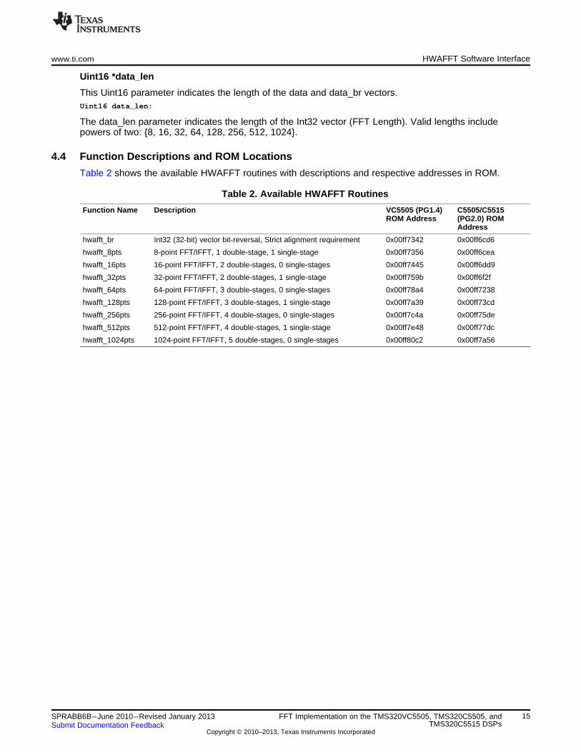
4.4 Function Descriptions and ROM Locations
Table 2 shows the available HWAFFT routines with descriptions and respective addresses in ROM.
Table 2. Available HWAFFT Routines
Function Name Description VC5505 (PG1.4) C5505/C5515ROM Address (PG2.0) ROM
Address
hwafft_br Int32 (32-bit) vector bit-reversal, Strict alignment requirement 0x00ff7342 0x00ff6cd6
hwafft_8pts 8-point FFT/IFFT, 1 double-stage, 1 single-stage 0x00ff7356 0x00ff6cea
hwafft_16pts 16-point FFT/IFFT, 2 double-stages, 0 single-stages 0x00ff7445 0x00ff6dd9
hwafft_32pts 32-point FFT/IFFT, 2 double-stages, 1 single-stage 0x00ff759b 0x00ff6f2f
hwafft_64pts 64-point FFT/IFFT, 3 double-stages, 0 single-stages 0x00ff78a4 0x00ff7238
hwafft_128pts 128-point FFT/IFFT, 3 double-stages, 1 single-stage 0x00ff7a39 0x00ff73cd
hwafft_256pts 256-point FFT/IFFT, 4 double-stages, 0 single-stages 0x00ff7c4a 0x00ff75de
hwafft_512pts 512-point FFT/IFFT, 4 double-stages, 1 single-stage 0x00ff7e48 0x00ff77dc
hwafft_1024pts 1024-point FFT/IFFT, 5 double-stages, 0 single-stages 0x00ff80c2 0x00ff7a56
15SPRABB6B–June 2010–Revised January 2013 FFT Implementation on the TMS320VC5505, TMS320C5505, andTMS320C5515 DSPsSubmit Documentation Feedback
Copyright © 2010–2013, Texas Instruments Incorporated

HWAFFT Software Interface www.ti.com
4.5 Project Configuration for Calling Functions from ROM
NOTE: To execute the HWAFFT routines from the ROM of the DSP, the programmer must satisfymemory allocation restrictions for the data and scratch buffers. See the device-specific erratafor an explanation of the restrictions and workarounds:
• TMS320VC5505/VC5504 Fixed-Point DSP Silicon Errata (Silicon Revision 1.4)[literature number SPRZ281]
• TMS320C5505/C5504 Fixed-Point DSP Silicon Errata (Silicon Revision 2.0)[literature number SPRZ310]
• TMS320C5515/C5514 Fixed-Point DSP Silicon Errata (Silicon Revision 2.0)[literature number SPRZ308]
The HWAFFT functions occupy approximately 4 KBytes of memory, so to conserve RAM they have beenplaced in the DSP’s 128 KBytes of on-chip ROM. These functions are identical to and have the samenames as the functions stored in hwafft.asm, but they do not consume any RAM. In order to utilize theseHWAFFT routines in ROM, add the following lines to the bottom of the project’s linker CMD file andremove the hwafft.asm file from the project (or exclude it from the build). When the project is rebuilt, theHWAFFT functions will reference the ROM locations. The HWAFFT ROM locations are different betweenVC5505 (PG1.4) and C5505/C5515 (PG2.0). ROM locations for both device families are shown in Table 2./*** Add the following code to the linker command file to call HWAFFT Routines from ROM ***/
/* HWAFFT Routines ROM Addresses *//* (PG1.4) *//*_hwafft_br = 0x00ff7342;_hwafft_8pts = 0x00ff7356;_hwafft_16pts = 0x00ff7445;_hwafft_32pts = 0x00ff759b;_hwafft_64pts = 0x00ff78a4;_hwafft_128pts = 0x00ff7a39;_hwafft_256pts = 0x00ff7c4a;_hwafft_512pts = 0x00ff7e48;_hwafft_1024pts = 0x00ff80c2;*/
/* HWAFFT Routines ROM Addresses *//* (PG 2.0) */_hwafft_br = 0x00ff6cd6;_hwafft_8pts = 0x00ff6cea;_hwafft_16pts = 0x00ff6dd9;_hwafft_32pts = 0x00ff6f2f;_hwafft_64pts = 0x00ff7238;_hwafft_128pts = 0x00ff73cd;_hwafft_256pts = 0x00ff75de;_hwafft_512pts = 0x00ff77dc;_hwafft_1024pts = 0x00ff7a56;
16 FFT Implementation on the TMS320VC5505, TMS320C5505, and SPRABB6B–June 2010–Revised January 2013TMS320C5515 DSPs Submit Documentation Feedback
Copyright © 2010–2013, Texas Instruments Incorporated

www.ti.com Simple Example to Illustrate the Use of the FFT Accelerator
5 Simple Example to Illustrate the Use of the FFT Accelerator
NOTE: To execute the HWAFFT routines from the ROM of the DSP, the programmer must satisfymemory allocation restrictions for the data and scratch buffers. See the device-specific erratafor an explanation of the restrictions and workarounds:
• TMS320VC5505/VC5504 Fixed-Point DSP Silicon Errata (Silicon Revision 1.4)[literature number SPRZ281]
• TMS320C5505/C5504 Fixed-Point DSP Silicon Errata (Silicon Revision 2.0)[literature number SPRZ310]
• TMS320C5515/C5514 Fixed-Point DSP Silicon Errata (Silicon Revision 2.0)[literature number SPRZ308]
The source code below demonstrates typical use of the HWAFFT for the 1024-point FFT and IFFT cases.
The HWAFFT Functions make use of Boolean flag variables to select between FFT and IFFT, Scale andNo Scale mode, and Data and Scratch output locations.
#define FFT_FLAG ( 0 ) /* HWAFFT to perform FFT */#define IFFT_FLAG ( 1 ) /* HWAFFT to perform IFFT */#define SCALE_FLAG ( 0 ) /* HWAFFT to scale butterfly output */#define NOSCALE_FLAG ( 1 ) /* HWAFFT not to scale butterfly output */#define OUT_SEL_DATA ( 0 ) /* Indicates HWAFFT output located in input data vector */#define OUT_SEL_SCRATCH ( 1 ) /* Indicates HWAFFT output located in scratch vector */Int32 *data;Int32 *data_br;Uint16 fft_flag;Uint16 scale_flag;Int32 *scratch;Uint16 out_sel;Int32 *result;
5.1 1024-Point FFT, Scaling Disabled
Compute 1024-point FFT with Scaling enabled: a ½ scale factor after every stage:fft_flag = FFT_FLAG;scale_flag = SCALE_FLAG;
data = <1024-point Complex input>;
/* Bit-Reverse 1024-point data, Store into data_br, data_br aligned to12-least significant binary zeros*/
hwafft_br(data, data_br, DATA_LEN_1024); /* bit-reverse input data,Destination buffer aligned */
data = data_br;
/* Compute 1024-point FFT, scaling enabled. */out_sel = hwafft_1024pts(data, scratch, fft_flag, scale_flag);
if (out_sel == OUT_SEL_DATA) {result = data;
}else {result = scratch;
}
17SPRABB6B–June 2010–Revised January 2013 FFT Implementation on the TMS320VC5505, TMS320C5505, andTMS320C5515 DSPsSubmit Documentation Feedback
Copyright © 2010–2013, Texas Instruments Incorporated
Simple Example to Illustrate the Use of the FFT Accelerator www.ti.com
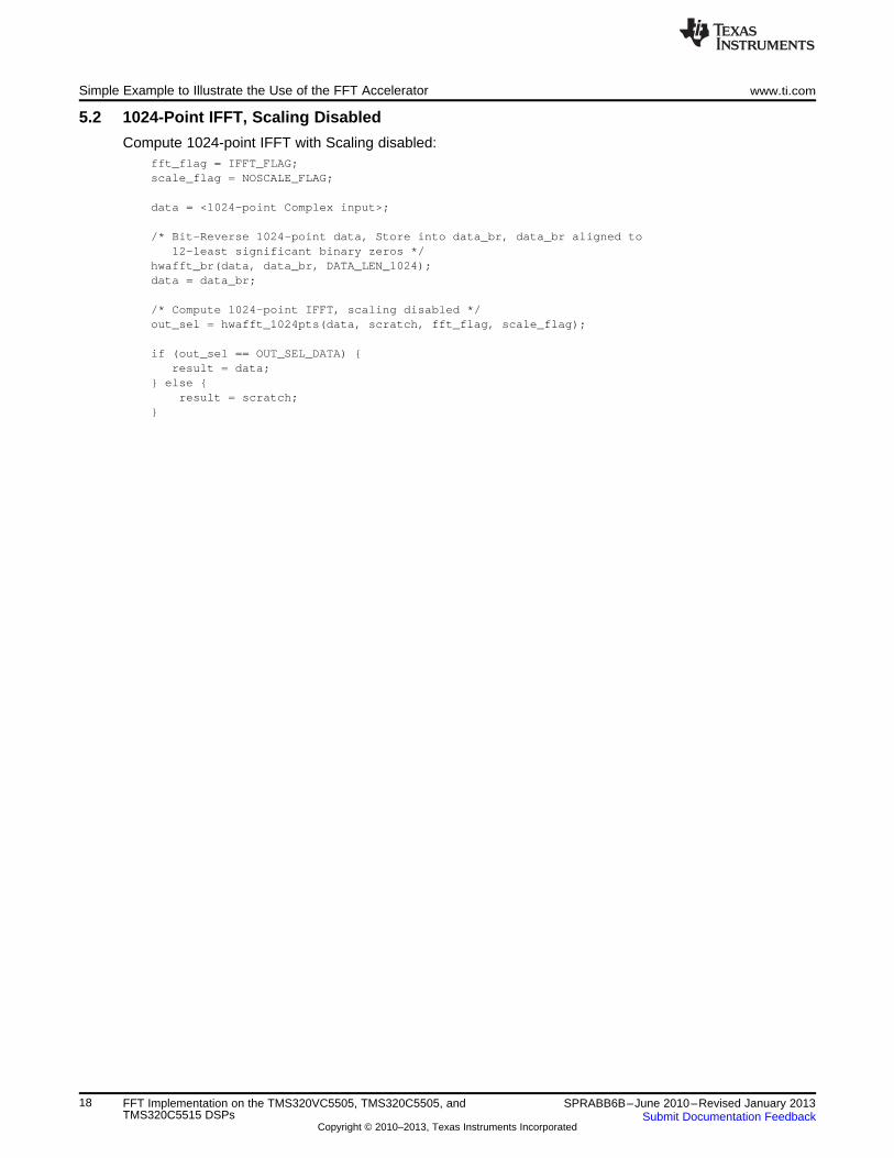
5.2 1024-Point IFFT, Scaling Disabled
Compute 1024-point IFFT with Scaling disabled:fft_flag = IFFT_FLAG;scale_flag = NOSCALE_FLAG;
data = <1024-point Complex input>;
/* Bit-Reverse 1024-point data, Store into data_br, data_br aligned to12-least significant binary zeros */
hwafft_br(data, data_br, DATA_LEN_1024);data = data_br;
/* Compute 1024-point IFFT, scaling disabled */out_sel = hwafft_1024pts(data, scratch, fft_flag, scale_flag);
if (out_sel == OUT_SEL_DATA) {result = data;
} else {result = scratch;
}
18 FFT Implementation on the TMS320VC5505, TMS320C5505, and SPRABB6B–June 2010–Revised January 2013TMS320C5515 DSPs Submit Documentation Feedback
Copyright © 2010–2013, Texas Instruments Incorporated

www.ti.com Simple Example to Illustrate the Use of the FFT Accelerator
5.3 Graphing FFT Results in CCS4
Code Composer includes a graphing utility that makes visualization of the FFT operation quick and easy.The Graph Utility is located in the CCSv4 window, under Tools → Graph → Single Time.
If the FFT Result is stored in scratch (OutSel = 1) and scratch is located at address 0x3000…
Plot the real part:
Figure 6. Graphing the Real Part of the FFT Result in CCS4
Plot the imaginary part:
Figure 7. Graphing the Imaginary Part of the FFT Result in CCS4
19SPRABB6B–June 2010–Revised January 2013 FFT Implementation on the TMS320VC5505, TMS320C5505, andTMS320C5515 DSPsSubmit Documentation Feedback
Copyright © 2010–2013, Texas Instruments Incorporated
FFT Benchmarks www.ti.com
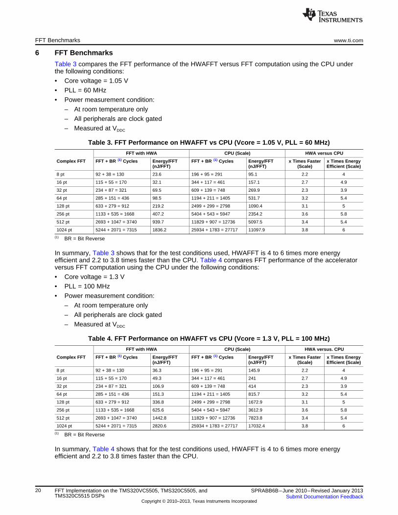
6 FFT Benchmarks
Table 3 compares the FFT performance of the HWAFFT versus FFT computation using the CPU underthe following conditions:
• Core voltage = 1.05 V
• PLL = 60 MHz
• Power measurement condition:
– At room temperature only
– All peripherals are clock gated
– Measured at VDDC
Table 3. FFT Performance on HWAFFT vs CPU (Vcore = 1.05 V, PLL = 60 MHz)
FFT with HWA CPU (Scale) HWA versus CPU
Complex FFT FFT + BR (1) Cycles Energy/FFT FFT + BR (1) Cycles Energy/FFT x Times Faster x Times Energy(nJ/FFT) (nJ/FFT) (Scale) Efficient (Scale)
8 pt 92 + 38 = 130 23.6 196 + 95 = 291 95.1 2.2 4
16 pt 115 + 55 = 170 32.1 344 + 117 = 461 157.1 2.7 4.9
32 pt 234 + 87 = 321 69.5 609 + 139 = 748 269.9 2.3 3.9
64 pt 285 + 151 = 436 98.5 1194 + 211 = 1405 531.7 3.2 5.4
128 pt 633 + 279 = 912 219.2 2499 + 299 = 2798 1090.4 3.1 5
256 pt 1133 + 535 = 1668 407.2 5404 + 543 = 5947 2354.2 3.6 5.8
512 pt 2693 + 1047 = 3740 939.7 11829 + 907 = 12736 5097.5 3.4 5.4
1024 pt 5244 + 2071 = 7315 1836.2 25934 + 1783 = 27717 11097.9 3.8 6
(1) BR = Bit Reverse
In summary, Table 3 shows that for the test conditions used, HWAFFT is 4 to 6 times more energyefficient and 2.2 to 3.8 times faster than the CPU. Table 4 compares FFT performance of the acceleratorversus FFT computation using the CPU under the following conditions:
• Core voltage = 1.3 V
• PLL = 100 MHz
• Power measurement condition:
– At room temperature only
– All peripherals are clock gated
– Measured at VDDC
Table 4. FFT Performance on HWAFFT vs CPU (Vcore = 1.3 V, PLL = 100 MHz)
FFT with HWA CPU (Scale) HWA versus. CPU
Complex FFT FFT + BR (1) Cycles Energy/FFT FFT + BR (1) Cycles Energy/FFT x Times Faster x Times Energy(nJ/FFT) (nJ/FFT) (Scale) Efficient (Scale)
8 pt 92 + 38 = 130 36.3 196 + 95 = 291 145.9 2.2 4
16 pt 115 + 55 = 170 49.3 344 + 117 = 461 241 2.7 4.9
32 pt 234 + 87 = 321 106.9 609 + 139 = 748 414 2.3 3.9
64 pt 285 + 151 = 436 151.3 1194 + 211 = 1405 815.7 3.2 5.4
128 pt 633 + 279 = 912 336.8 2499 + 299 = 2798 1672.9 3.1 5
256 pt 1133 + 535 = 1668 625.6 5404 + 543 = 5947 3612.9 3.6 5.8
512 pt 2693 + 1047 = 3740 1442.8 11829 + 907 = 12736 7823.8 3.4 5.4
1024 pt 5244 + 2071 = 7315 2820.6 25934 + 1783 = 27717 17032.4 3.8 6
(1) BR = Bit Reverse
In summary, Table 4 shows that for the test conditions used, HWAFFT is 4 to 6 times more energyefficient and 2.2 to 3.8 times faster than the CPU.
20 FFT Implementation on the TMS320VC5505, TMS320C5505, and SPRABB6B–June 2010–Revised January 2013TMS320C5515 DSPs Submit Documentation Feedback
Copyright © 2010–2013, Texas Instruments Incorporated

Overlap&
Add
InBuf 1
InBuf 2 OutBuf 2
OutBuf 1
FFT IFFT
FFT
CPLXMUL
FilterCoeffs
From Codec orWaveforms in
Memory
To Codec
www.ti.com Description of Open Source FFT Example Software
7 Description of Open Source FFT Example Software
An example application of the HWAFFT used in a real-time audio filter is available on the Open SourceC5505 eZdsp website (http://www.code.google.com/p/c5505-ezdsp). The zip file named “VC5505 FFTFilter Demo” contains a Code Composer 4 Project and source code that implements a real-time low-passfilter on the VC5505 eZdsp USB Stick. Low-pass filtering is achieved through multiplication with a filter inthe Frequency Domain. Recall that multiplication in the frequency domain is equivalent to convolution inthe time domain.
In this demo, 16-bit stereo samples are captured by the AIC3204 codec at a sampling frequency of 48 kHzand copied to the DSP memory with the DMA over the Inter-IC Sound (I2S) bus. Samples from the left andright channel are collected in separate ping-pong buffers. When the buffer becomes full a DMA interruptupdates the ping-pong buffer and triggers the FFT filter to convolve the new block of samples with the low-pass filter.
Filtering is performed in three steps:
1. Use the HWAFFT to calculate the FFT of the input block of samples from the ping-pong buffers.
2. Multiply this complex FFT result with the pre-computed FFT result of the filter coefficients.
Note: The FFT result of the filter coefficients is computed once during program initialization and storedfor reuse.
3. Calculate the IFFT of that product on the HWAFFT.
Because a stream of samples is constantly arriving at the codec and block processing is utilized to filterthe signal, the Constant-Overlap-and-Add (COLA) method is implemented to output a continuous, glitch-free signal to the codec. Finally, the resulting block of filtered and overlapped samples is transferred backto the codec for output with the DMA over the I2S bus.
This demo provides you control over FFT Lengths (from 8 to 1024 points) and Filter Lengths (from 7 tapsto 511 taps) for a thorough comparison. Additionally, simulation modes are available for using idealsinusoidal signals (stored in memory) as inputs to the FFT Filter Demo.
The block diagram in Figure 8 shows the data flow for one channel of the FFT Filter Demo. Whenprocessing stereo input (separate left and right channels), this data flow is duplicated for each channel.
Figure 8. FFT Filter Demo Block Diagram
21SPRABB6B–June 2010–Revised January 2013 FFT Implementation on the TMS320VC5505, TMS320C5505, andTMS320C5515 DSPsSubmit Documentation Feedback
Copyright © 2010–2013, Texas Instruments Incorporated

1( / 2) ( ( ) - ( )), 0 / 2 - 1
2
kX k N X k W X k k to N
even N odd
+ = =
1( ) ( ( ) ( )), 0 / 2 - 1
2
kX k X k W X k k to N
even N odd
= + =
Computation of Large (Greater Than 1024-Point) FFTs www.ti.com
8 Computation of Large (Greater Than 1024-Point) FFTs
The HWAFFT can perform up to 1024-point complex FFTs/IFFTs at a maximum, but if larger FFT sizes(i.e. 2048-point) are required, the DSP core can be used to compute extra Radix-2 stages that are toolarge for the HWAFFT to handle.
Recall the Radix-2 DIT equations:
(11)
and
(12)
8.1 Procedure for Computing Large FFTs
The procedure for computing an additional Radix-2 DIT stage on the CPU is outlined:
• Split the input signal into even and odd indexed signals, Xeven and Xodd.
• Call N/2 point FFTs for the even and odd indexed inputs.
• Complex Multiply the Xodd FFT results with the decimated twiddle factors for that stage.
• Add the Xodd * Twiddle product to Xeven to find the first half of the FFT result.
• Subtract Xodd * Twiddle to find the second half of the FFT result.
8.2 Twiddle Factor Computation
The HWAFFT stores 512 complex twiddle factors enabling FFT/IFFT computations up to 1024 points.Recall Equation 5 states that only twiddle factors from 0 to N/2 are needed. To compute FFT/IFFTs largerthan 1024 points, you must supply N/2 complex twiddle factors, where N is the FFT length (powers of 2).
The following MATLAB code creates real and imaginary parts of the twiddle factors for any N:N = 2048;n = 0:(N/2-1);twid_r = cos(2*pi*n/N);twid_i = -sin(2*pi*n/N);
8.3 Bit-Reverse Separates Even and Odd Indexes
A nice property of the bit-reversal process is the automatic separation of odd-indexed data from even-indexed data. Before the bit-reverse, even indexes have a 0 in the least significant bit and odd indexeshave a 1 in the least significant bit. After the bit-reverse, even indexes have a 0 in the most significant bit,and odd indexes have a 1 in the most significant bit. Therefore, all even indexed data resides in the firsthalf of the bit-reversed vector, and all odd indexed data resides in the second half of the bit-reversedvector. This process meets two needs: separation of even and odd indexed-data vectors and bit-reversingboth vectors.
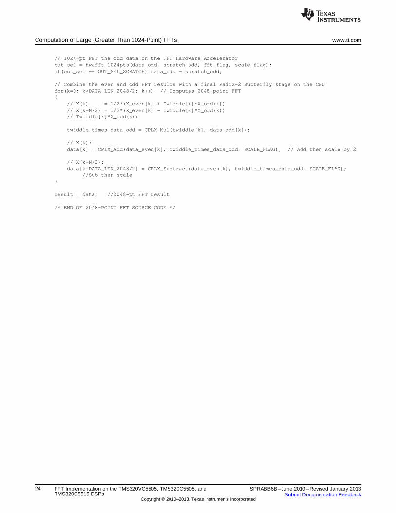
8.4 2048-point FFT Source Code
The following C source code demonstrates a 2048-point FFT using this approach. Two 1024-point FFTsare computed on the HWAFFT, and a final Radix-2 stage is performed on the CPU to generate a 2048-point FFT result:#define FFT_FLAG ( 0 ) /* HWAFFT to perform FFT */#define IFFT_FLAG ( 1 ) /* HWAFFT to perform IFFT */#define SCALE_FLAG ( 0 ) /* HWAFFT to scale butterfly output */#define NOSCALE_FLAG ( 1 ) /* HWAFFT not to scale butterfly output */#define OUT_SEL_DATA ( 0 ) /* Indicates HWAFFT output located in input data vector */#define OUT_SEL_SCRATCH ( 1 ) /* Indicates HWAFFT output located in scratch vector */#define DATA_LEN_2048 ( 2048 )#define TEST_DATA_LEN (DATA_LEN_2048)
// Static Memory Allocations and Alignment:#pragma DATA_SECTION(data_br_buf, "data_br_buf");
22 FFT Implementation on the TMS320VC5505, TMS320C5505, and SPRABB6B–June 2010–Revised January 2013TMS320C5515 DSPs Submit Documentation Feedback
Copyright © 2010–2013, Texas Instruments Incorporated

www.ti.com Computation of Large (Greater Than 1024-Point) FFTs
#pragma DATA_ALIGN (data_br_buf, 4096);// Align 2048-pt bit-reverse dest vector to byte addr w/ 13 least sig zeros
Int32 data_br_buf[TEST_DATA_LEN];
#pragma DATA_SECTION(data_even_buf, "data_even_buf");Int32 data_even_buf[TEST_DATA_LEN/2];
#pragma DATA_SECTION(data_odd_buf, "data_odd_buf");Int32 data_odd_buf[TEST_DATA_LEN/2];
#pragma DATA_SECTION(scratch_even_buf, "scratch_even_buf");Int32 scratch_even_buf[TEST_DATA_LEN/2];
#pragma DATA_SECTION(scratch_odd_buf, "scratch_odd_buf");Int32 scratch_odd_buf[TEST_DATA_LEN/2];
// Function Prototypes:Int32 CPLX_Mul(Int32 op1, Int32 op2);
// Yr = op1_r*op2*r - op1_i*op2_i, Yi = op1_r*op2_i + op1_i*op2_rInt32 CPLX_Add(Int32 op1, Int32 op2, Uint16 scale_flag);
// Yr = 1/2 * (op1_r + op2_r), Yi = 1/2 *(op1_i + op2_i)Int32 CPLX_Subtract(Int32 op1, Int32 op2, Uint16 scale_flag);
// Yr = 1/2 * (op1_r - op2_r), Yi = 1/2 *(op1_i - op2_i)
// Declare VariablesInt32 *data_br;Int32 *data;Int32 *data_even, *data_odd;Int32 *scratch_even, *scratch_odd;Int32 *twiddle;Int32 twiddle_times_data_odd;Uint16 fft_flag;Uint16 scale_flag;Uint16 out_sel;Uint16 k;
// Assign pointers to static memory allocationsdata_br = data_br_buf;data_even = data_even_buf;data_odd = data_odd_buf;scratch_even = scratch_even_buf;scratch_odd = scratch_odd_buf;twiddle = twiddle_buf; // 1024-pt Complex Twiddle Tabledata = invec_fft_2048pts; // 2048-pt Complex Input Vector
// HWAFFT flags:fft_flag = FFT_FLAG; // HWAFFT to perform FFT (not IFFT)scale_flag = SCALE_FLAG; // HWAFFT to scale by 2 after each butterfly stage
// Bit-reverse input data for DIT FFT calculationhwafft_br(data, data_br, DATA_LEN_2048);
// data_br aligned to log2(4*2048) = 13 zeros in least sig bitsdata = data_br;
// Split data into even-indexed data & odd-indexed data// data is already bit-reversed, so even-indexed data = first half & odd-indexed data = second halffor(k=0; k<DATA_LEN_2048/2; k++){
data_even[k] = data[k];data_odd[k] = data[k+DATA_LEN_2048/2];
}
// 1024-pt FFT the even data on the FFT Hardware Acceleratorout_sel = hwafft_1024pts(data_even, scratch_even, fft_flag, scale_flag);if(out_sel == OUT_SEL_SCRATCH) data_even = scratch_even;
23SPRABB6B–June 2010–Revised January 2013 FFT Implementation on the TMS320VC5505, TMS320C5505, andTMS320C5515 DSPsSubmit Documentation Feedback
Copyright © 2010–2013, Texas Instruments Incorporated
Computation of Large (Greater Than 1024-Point) FFTs www.ti.com
// 1024-pt FFT the odd data on the FFT Hardware Acceleratorout_sel = hwafft_1024pts(data_odd, scratch_odd, fft_flag, scale_flag);if(out_sel == OUT_SEL_SCRATCH) data_odd = scratch_odd;
// Combine the even and odd FFT results with a final Radix-2 Butterfly stage on the CPUfor(k=0; k<DATA_LEN_2048/2; k++) // Computes 2048-point FFT{
// X(k) = 1/2*(X_even[k] + Twiddle[k]*X_odd(k))// X(k+N/2) = 1/2*(X_even[k] - Twiddle[k]*X_odd(k))// Twiddle[k]*X_odd(k):
twiddle_times_data_odd = CPLX_Mul(twiddle[k], data_odd[k]);
// X(k):data[k] = CPLX_Add(data_even[k], twiddle_times_data_odd, SCALE_FLAG); // Add then scale by 2
// X(k+N/2):data[k+DATA_LEN_2048/2] = CPLX_Subtract(data_even[k], twiddle_times_data_odd, SCALE_FLAG);
//Sub then scale}
result = data; //2048-pt FFT result
/* END OF 2048-POINT FFT SOURCE CODE */
24 FFT Implementation on the TMS320VC5505, TMS320C5505, and SPRABB6B–June 2010–Revised January 2013TMS320C5515 DSPs Submit Documentation Feedback
Copyright © 2010–2013, Texas Instruments Incorporated
www.ti.com Appendix A Methods for Aligning the Bit-Reverse Destination Vector
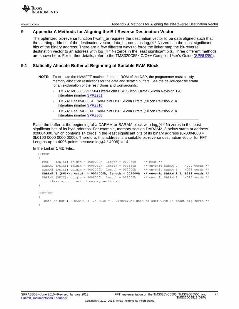
9 Appendix A Methods for Aligning the Bit-Reverse Destination Vector
The optimized bit-reverse function hwafft_br requires the destination vector to be data aligned such thatthe starting address of the destination vector, data_br, contains log2(4 * N) zeros in the least significantbits of the binary address. There are a few different ways to force the linker map the bit-reversedestination vector to an address with log2(4 * N) zeros in the least significant bits. Three different methodsare shown here. For further details, refer to the TMS320C55x C/C++ Compiler User’s Guide (SPRU280).
9.1 Statically Allocate Buffer at Beginning of Suitable RAM Block
NOTE: To execute the HWAFFT routines from the ROM of the DSP, the programmer must satisfymemory allocation restrictions for the data and scratch buffers. See the device-specific erratafor an explanation of the restrictions and workarounds:
• TMS320VC5505/VC5504 Fixed-Point DSP Silicon Errata (Silicon Revision 1.4)[literature number SPRZ281]
• TMS320C5505/C5504 Fixed-Point DSP Silicon Errata (Silicon Revision 2.0)[literature number SPRZ310]
• TMS320C5515/C5514 Fixed-Point DSP Silicon Errata (Silicon Revision 2.0)[literature number SPRZ308]
Place the buffer at the beginning of a DARAM or SARAM block with log2(4 * N) zeros in the leastsignificant bits of its byte address. For example, memory section DARAM2_3 below starts at address0x0004000, which contains 14 zeros in the least significant bits of its binary address (0x0004000 =0b0100 0000 0000 0000). Therefore, this address is a suitable bit-reverse destination vector for FFTLengths up to 4096-points because log2(4 * 4096) = 14.
In the Linker CMD File...MEMORY{MMR (RWIX): origin = 0000000h, length = 0000c0h /* MMRs */DARAM0 (RWIX): origin = 00000c0h, length = 001f40h /* on-chip DARAM 0, 4000 words */DARAM1 (RWIX): origin = 0002000h, length = 002000h /* on-chip DARAM 1, 4096 words */DARAM2_3 (RWIX): origin = 0004000h, length = 004000h /* on-chip DARAM 2_3, 8192 words */DARAM4 (RWIX): origin = 0008000h, length = 002000h /* on-chip DARAM 4, 4096 words */... (leaving out rest of memory sections)
}
SECTIONS{
data_br_buf : > DARAM2_3 /* ADDR = 0x004000, Aligned to addr with 14 least-sig zeros */}
25SPRABB6B–June 2010–Revised January 2013 FFT Implementation on the TMS320VC5505, TMS320C5505, andTMS320C5515 DSPsSubmit Documentation Feedback
Copyright © 2010–2013, Texas Instruments Incorporated

Appendix A Methods for Aligning the Bit-Reverse Destination Vector www.ti.com
9.2 Use the ALIGN Descriptor to Force log2(4 * N) Zeros in the Least Significant Bits
The ALIGN descriptor forces the alignment of a specific memory section, while providing the linker withadded flexibility to allocate sections across the entire DARAM or SARAM because no blocks are staticallyallocated. It aligns the memory section to an address with log2(ALIGN Value) zeros in the least significantbits of the binary address.
For example, the following code aligns data_br_buf to an address with 12 zeros in the least significantbits, suitable for a 1024-point bit-reverse destination vector.
In the Linker CMD File...MEMORY{MMR (RWIX): origin = 0000000h, length = 0000c0h /* MMRs */DARAM (RWIX): origin = 00000c0h, length = 00ff40h /* on-chip DARAM 32 Kwords */SARAM (RWIX): origin = 0010000h, length = 040000h /* on-chip SARAM 128 Kwords */
}
SECTIONS{
data_br_buf : > DARAM ALIGN = 4096/* 2^12 = 4096 , Aligned to addr with 12 least-sig zeros */
}
9.3 Use the DATA_ALIGN Pragma
The DATA_ALIGN pragma is placed in the source code where the vector is defined. The syntax is shownbelow.
#pragma DATA_ALIGN (symbol, constant);
The DATA_ALIGN pragma aligns the symbol to an alignment boundary. The boundary is the value of theconstant in words. For example, a constant of 4 specifies a 64-bit alignment. The constant must be apower of 2.
In this example, a constant of 2048 aligns the data_br_buf symbol to an address with 12 zeros in the leastsignificant bits, suitable for a 1024-point bit-reverse destination vector.
In the source file where data_br is declared (e.g. main.c)...#pragma DATA_SECTION(data_br_buf, "data_br_buf");#pragma DATA_ALIGN (data_br_buf, 2048);Int32 data_br_buf[TEST_DATA_LEN];
26 FFT Implementation on the TMS320VC5505, TMS320C5505, and SPRABB6B–June 2010–Revised January 2013TMS320C5515 DSPs Submit Documentation Feedback
Copyright © 2010–2013, Texas Instruments Incorporated
www.ti.com
Appendix A Revision History
This revision history highlights the changes made to this document to make it a SPRABB6B revision.
Table 5. Revision History
See Revision
Added notes to satisfy memory allocation restrictions for the data and scratch FFTEntire document buffers before executing HWAFFT routines from the ROM of the DSP.
27SPRABB6B–June 2010–Revised January 2013 FFT Implementation on the TMS320VC5505, TMS320C5505, andTMS320C5515 DSPsSubmit Documentation Feedback
Copyright © 2010–2013, Texas Instruments Incorporated

IMPORTANT NOTICE
Texas Instruments Incorporated and its subsidiaries (TI) reserve the right to make corrections, enhancements, improvements and otherchanges to its semiconductor products and services per JESD46, latest issue, and to discontinue any product or service per JESD48, latestissue. Buyers should obtain the latest relevant information before placing orders and should verify that such information is current andcomplete. All semiconductor products (also referred to herein as “components”) are sold subject to TI’s terms and conditions of salesupplied at the time of order acknowledgment.
TI warrants performance of its components to the specifications applicable at the time of sale, in accordance with the warranty in TI’s termsand conditions of sale of semiconductor products. Testing and other quality control techniques are used to the extent TI deems necessaryto support this warranty. Except where mandated by applicable law, testing of all parameters of each component is not necessarilyperformed.
TI assumes no liability for applications assistance or the design of Buyers’ products. Buyers are responsible for their products andapplications using TI components. To minimize the risks associated with Buyers’ products and applications, Buyers should provideadequate design and operating safeguards.
TI does not warrant or represent that any license, either express or implied, is granted under any patent right, copyright, mask work right, orother intellectual property right relating to any combination, machine, or process in which TI components or services are used. Informationpublished by TI regarding third-party products or services does not constitute a license to use such products or services or a warranty orendorsement thereof. Use of such information may require a license from a third party under the patents or other intellectual property of thethird party, or a license from TI under the patents or other intellectual property of TI.
Reproduction of significant portions of TI information in TI data books or data sheets is permissible only if reproduction is without alterationand is accompanied by all associated warranties, conditions, limitations, and notices. TI is not responsible or liable for such altereddocumentation. Information of third parties may be subject to additional restrictions.
Resale of TI components or services with statements different from or beyond the parameters stated by TI for that component or servicevoids all express and any implied warranties for the associated TI component or service and is an unfair and deceptive business practice.TI is not responsible or liable for any such statements.
Buyer acknowledges and agrees that it is solely responsible for compliance with all legal, regulatory and safety-related requirementsconcerning its products, and any use of TI components in its applications, notwithstanding any applications-related information or supportthat may be provided by TI. Buyer represents and agrees that it has all the necessary expertise to create and implement safeguards whichanticipate dangerous consequences of failures, monitor failures and their consequences, lessen the likelihood of failures that might causeharm and take appropriate remedial actions. Buyer will fully indemnify TI and its representatives against any damages arising out of the useof any TI components in safety-critical applications.
In some cases, TI components may be promoted specifically to facilitate safety-related applications. With such components, TI’s goal is tohelp enable customers to design and create their own end-product solutions that meet applicable functional safety standards andrequirements. Nonetheless, such components are subject to these terms.
No TI components are authorized for use in FDA Class III (or similar life-critical medical equipment) unless authorized officers of the partieshave executed a special agreement specifically governing such use.
Only those TI components which TI has specifically designated as military grade or “enhanced plastic” are designed and intended for use inmilitary/aerospace applications or environments. Buyer acknowledges and agrees that any military or aerospace use of TI componentswhich have not been so designated is solely at the Buyer's risk, and that Buyer is solely responsible for compliance with all legal andregulatory requirements in connection with such use.
TI has specifically designated certain components as meeting ISO/TS16949 requirements, mainly for automotive use. In any case of use ofnon-designated products, TI will not be responsible for any failure to meet ISO/TS16949.
Products Applications
Audio www.ti.com/audio Automotive and Transportation www.ti.com/automotive
Amplifiers amplifier.ti.com Communications and Telecom www.ti.com/communications
Data Converters dataconverter.ti.com Computers and Peripherals www.ti.com/computers
DLP® Products www.dlp.com Consumer Electronics www.ti.com/consumer-apps
DSP dsp.ti.com Energy and Lighting www.ti.com/energy
Clocks and Timers www.ti.com/clocks Industrial www.ti.com/industrial
Interface interface.ti.com Medical www.ti.com/medical
Logic logic.ti.com Security www.ti.com/security
Power Mgmt power.ti.com Space, Avionics and Defense www.ti.com/space-avionics-defense
Microcontrollers microcontroller.ti.com Video and Imaging www.ti.com/video
RFID www.ti-rfid.com
OMAP Applications Processors www.ti.com/omap TI E2E Community e2e.ti.com
Wireless Connectivity www.ti.com/wirelessconnectivity
Mailing Address: Texas Instruments, Post Office Box 655303, Dallas, Texas 75265Copyright © 2013, Texas Instruments Incorporated