制御システムの安全関連部 iso 13849-1iso 13849-1とは?3 •...
TRANSCRIPT

第3版概要第4版改正の動向第3版対応JIS改正の動向
制御システムの安全関連部
ISO 13849-1
テュフラインランテュフラインランテュフラインランテュフラインランドドドドジャパジャパジャパジャパンンンン株式会株式会株式会株式会社社社社
製製製製品部品部品部品部 産業機器課産業機器課産業機器課産業機器課
杉杉杉杉田田田田 吉吉吉吉広広広広

目次
2
1. ISO 13849-1とは?
1. 適用範囲
2. 関連規格(引用規格)
2. ISO 13849-1概要
1. 適用例
3. 改正履歴
4. 第4版改正動向
5. 第3版対応JIS改正動向

ISO 13849-1とは?
3
• ソフトウエアを含み、制御システムの安全関連部
(SRP/CS)の設計及び統合のための原則に関する安全要求事項及び指針について規定。
• SRP/CSに対して、安全機能を実行するために要求されるパフォーマンスレベルを含む特性について規定。
• 安全関連部が安全機能を遂行する能力をパフォーマンスレ
ベル(PL)とし、単位時間当たりの危険側故障発生確率(Probability of a Dangerous Failure,PFHD)で規定する。
• 高頻度作動要求又は連続モードに適用する。
適用範囲
PL 単位時間当たりの危険側故障発生の平均確率
(PFHD)
1/ha 10-5
≦ PFHD<10-4
b 3×10⁻⁶≦ PFHD<10-5
c 10-6≦ PFHD<3×10⁻⁶
d 10-7≦ PFHD<10-6
e 10-8≦ PFHD<10-7
序文より
• 達成したPLの査定を容易にするために、構造分類(カテゴリ、B, 1, 2, 3, 4の5分類)• 適用される制御システムの安全関連部
• 保護装置(例:両手操作制御装置、インタロック装置)、電気的検知保護装置(例:ライトカーテン)、圧力検知装置
• 制御ユニット(例:制御機能の論理ユニット、データ処理、監視など)
• 動力制御要素(例:リレー、バルブなど)
• あらゆる種類の機械類に適用
• 単純な据付装置(例:小さな調理用機械、又は自動ドア及びゲート)
• 製造用の据付装置(例:包装機械、印刷機械、プレス機械)

ISO 13849-1とは?
4
ISO 13849-2: 2012 - Safety of machinery - Safety-related parts of control systems - Part 2: Validation
機械類の安全性‐制御システムの安全関連部-第2部:妥当性確認
ISO/TR 23849: 2010 - Guidance on the application of ISO 13849-1 and IEC 62061 in the design of safety-related control systems for machinery
機械類の安全関連制御システムにISO 13849-1及びIEC 62061を適用する際のガイダンス
ISO/TR 22100-2: 2013, Safety of machinery - Relationship with ISO 12100 - Part 2: How ISO 12100 relates to ISO 13849-1
機械類の安全性 - ISO12100との関係-第2部ISO 12100とISO 13849-1との関係
IEC 62061+A1+A2:2015: Safety of machinery - Functional safety of safety–related electrical, electronic and
programmable electronic control systems
機械類の安全性 − 安全関連の電気・電子・プログラマブル電子制御システムの機能安全
IEC 61508-3/-4: Functional safety of electrical/electronic/programmable electronic safety-related systems - Part 3: Software requirements/Part4:Definitions and abbreviations
関連規格(引用規格)

ISO 13849-1概要
5
この反復的リスク低減プロセ
スは,各使用条件(タスク)
下で危険源の各々について,
個別に実施しなければならな
い。
いいえ
終了
開始
JIS B 9700に従って実施したリス
クアセスメント
機械類の制限の決定
(JIS B 9700の5.3参照)
危険源の同定
(箇条箇条箇条箇条4及びJIS B 9700の5.4参照)
リスクの見積り
(JIS B 9700の5.5参照)
リスクの評価
(JIS B 9700の 5.6参照)
リスクは適切に
低減されたか?
危険源に対するリスク低減プロセス
1 本質的安全設計方策による
2 安全防護物による安全防護物による安全防護物による安全防護物による
3 使用上の情報による
(JIS B 9700の図図図図1111参照)
選択した保護方選択した保護方選択した保護方選択した保護方
策は制御システ策は制御システ策は制御システ策は制御システ
ムによるかムによるかムによるかムによるか????
他の危険源は生
じるか?
はい
いいえ
はい
いいえ
はい
制御システムの安全関連部制御システムの安全関連部制御システムの安全関連部制御システムの安全関連部((((SRP/CS))))の反復的プロセスの反復的プロセスの反復的プロセスの反復的プロセス
((((図図図図3 a) 参照)参照)参照)参照)
注記注記注記注記 この点線内の詳細をこの点線内の詳細をこの点線内の詳細をこの点線内の詳細を,,,,図図図図3に示に示に示に示
すすすす。。。。
図1 – リスクアセスメントとリスク低減
リスクアセスメントの結果、リス
ク低減を安全機能をもつ安全防護
物の使用により達成する場合
安全機能を提供するために割り当
てられる機械の制御システムの部
分は,制御システムの安全関連部
(SRP/CS)とし,ハードウェア及びソフトウェアで構成すること
ができる。

ISO 13849-1概要
6
図3-制御システムの安全関連部(SRP/CS)の設計のための反復的プロセス
安全機能の同定
要求特性の指定
要求PLrの決定
安全関連部の特定
PLの見積もり
カテゴリ
MTTFD
DC
CCF
システマティック故障
ソフトウエア(使用されていれば)
PLの検証(PL≥PLr)
妥当性確認
ISO 13849-1概要
7
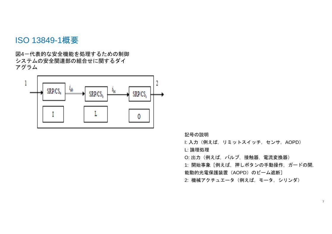
図4-代表的な安全機能を処理するための制御システムの安全関連部の組合せに関するダイ
アグラム
記号の説明
I: 入力(例えば,リミットスイッチ,センサ,AOPD)
L: 論理処理
O: 出力(例えば,バルブ,接触器,電流変換器)
1: 開始事象[例えば,押しボタンの手動操作,ガードの開,
能動的光電保護装置(AOPD)のビーム遮断]
2: 機械アクチュエータ(例えば,モータ,シリンダ)

ISO 13849-1適用例
8
例 機械のインターロックガードの停止機能
ISO/TR23849 8章 図1
I 入力(リミットスイッチ、B1, B2)
L 論理処理(安全モジュール、K1)
O 出力(コンタクタ、Q1, Q2)
安全機能:インターロックガード開でモータ停止
要求パフォーマンスレベル (PLr):e
ハードウエア構成:カテゴリ4

ISO 13849-1概要
9
安全機能の仕様
安全関連ブロック図に展開
サブシステムサブシステムサブシステムサブシステム 仕様仕様仕様仕様 備考備考備考備考
安全モジュール、K1 PFHD=2.31x10⁻⁹ (1/h)カテゴリ4、PL=e
メーカー提供
リミットスイッチ、B1 B10d=1,000,000回IEC 60947-5-1, Annex K
メーカー提供
リミットスイッチ、B2 B10d=500,000回 メーカー提供
コンタクタ、Q1, Q2 B10=1,000,000回IEC 60947-5-1, Annex L
メーカー提供
安全側・危険側故障は同率とし
B10d=2,000,000回とする
安全関連部仕様(一部)
詳細設定はISO/TR 23849参照

ISO 13849-1概要
10
機械仕様
機械仕様機械仕様機械仕様機械仕様 仕様仕様仕様仕様 備考備考備考備考1
年間稼働日 365日 ISO/TR 23849による
1日の稼働時間 24時間 ISO/TR 23849による
サイクルタイム 900s (15min) ISO/TR 23849による
年間作動回数 Nop=35,040/年 式(C.2)
詳細仕様はISO/TR 23849参照

ISO 13849-1概要
11
安全関連部評価
安全関連部評価安全関連部評価安全関連部評価安全関連部評価 備考備考備考備考1
MTTFD, B1 285年 式(C.7)
MTTFD, B2 143年
MTTFD, Q1/Q2 571年
1/MTTFD, ch1 1/190年 式(D.1)
1/MTTFD, ch2 1/114年
MTTFD 154年 式(D.2)、各チャンネルのMTTFDが異なるため
DC, B1/B2 99% 表E.1: K1によるプラウザビリティ(確かさ)監視
DC, Q1/Q2 99% 表E.1: K1による始動時の監視
DCavg 99%=“高” 式(E.1)
CCF 70 表F.1:分離/隔離(15)、十分吟味されたコンポーネントの使用(5)、過電圧等に対する保護(15)、環境面(25+10)
Mission time (使命時間)
20年 4.5.4項

ISO 13849-1概要
12
危険側故障の平均確率(1/h)及び対応のパフォーマンスレベルPL
各チャネルのMTTFD
年
カテゴリB PLDCavg=“なし”
カテゴリ1 PLDCavg=“なし”
カテゴリ2 PLDCavg=”低”
カテゴリ2 PLDCavg=”中”
カテゴリ3 PLDCavg=”低”
カテゴリ3 PLDCavg=”中”
カテゴリ4 PLDCavg=”高”
B1/B2/Q1/Q2)のPFHD
:表K.1、カテゴリ4、DCavg =”高”:PFHD
= 1.61x10⁻⁸
、PL = e
安全モジュール、K1のPFHD
を加えた安全関連部全体のPFHD
:2.31x102.31x102.31x102.31x10----9999
+1.61x10+1.61x10+1.61x10+1.61x10----8888
=1.84x10=1.84x10=1.84x10=1.84x10----8888
=> PL=e=> PL=e=> PL=e=> PL=e に相当に相当に相当に相当
36 3.17×10⁻⁶ b 1.67×10⁻⁶ c 9.39×10⁻⁷ d 5.16×10⁻⁷ d 2.01×10⁻⁷ d 7.77×10⁻⁸ e39 2.93×10⁻⁶ c 1.53×10⁻⁶ c 8.40×10⁻⁷ d 4.53×10⁻⁷ d 1.78×10⁻⁷ d 7.11×10⁻⁸ e43 2.65×10⁻⁶ c 1.37×10⁻⁶ c 7.34×10⁻⁷ d 3.87×10⁻⁷ d 1.54×10⁻⁷ d 6.37×10⁻⁸ e47 2.43×10⁻⁶ c 1.24×10⁻⁶ c 6.49×10⁻⁷ d 3.35×10⁻⁷ d 1.34×10⁻⁷ d 5.76×10⁻⁸ e51 2.24×10⁻⁶ c 1.13×10⁻⁶ c 5.80×10⁻⁷ d 2.93×10⁻⁷ d 1.19×10⁻⁷ d 5.26×10⁻⁸ e56 2.04×10⁻⁶ c 1.02×10⁻⁶ c 5.10×10⁻⁷ d 2.52×10⁻⁷ d 1.03×10⁻⁷ d 4.73×10⁻⁸ e62 1.84×10⁻⁶ c 9.06×10⁻⁷ d 4.43×10⁻⁷ d 2.13×10⁻⁷ d 8.84×10⁻⁸ e 4.22×10⁻⁸ e68 1.68×10⁻⁶ c 8.17×10⁻⁷ d 3.90×10⁻⁷ d 1.84×10⁻⁷ d 7.68×10⁻⁸ e 3.80×10⁻⁸ e75 1.52×10⁻⁶ c 7.31×10⁻⁷ d 3.40×10⁻⁷ d 1.57×10⁻⁷ d 6.62×10⁻⁸ e 3.41×10⁻⁸ e82 1.39×10⁻⁶ c 6.61×10⁻⁷ d 3.01×10⁻⁷ d 1.35×10⁻⁷ d 5.79×10⁻⁸ e 3.08×10⁻⁸ e91 1.25×10⁻⁶ c 5.88×10⁻⁷ d 2.61×10⁻⁷ d 1.14×10⁻⁷ d 4.94×10⁻⁸ e 2.74×10⁻⁸ e
100 1.14×10⁻⁶ c 5.28×10⁻⁷ d 2.29×10⁻⁷ d 1.01×10⁻⁷ d 4.29×10⁻⁸ e 2.47×10⁻⁸ e110 2.23 × 10⁻⁸ e
120 2,03 × 10⁻⁸ e
130 1,87 × 10⁻⁸ e
150 1,61 × 10⁻⁸ e
注:ISO/TR 23849:2010発行時は表K.1のカテゴリ4のMTTFD
は100年
に制限されていたので、このPFHD
はTRと異なる。

改正履歴
13
• 1999年11月 第1版発行
• 2006年11月 第2版発行
• 2009年9月 正誤表(Corrigenda)発行
• 2011年4月 追補発行を決定
• 2011年11月第9回WGより、ISO 13849-1追補に対するコメント審議開始
• 2012年1月追補1を発行するNWIP+CDが発行、10月に承認
• 2013年1月第12回WGでCDに対するコメント審議終了、DIS発行手続き
• 2014年3月第16回WGでDISに対するコメント審議終了、FDIS発行手続き
• 2014年9月追補のFDIS(ISO 13849-1 FDAM1)発行
• 2015年10月 ISO/TC199年次大会でISO/IEC17305の開発中止が決定及びISO13849-1の更なる改定又は追補の発行を決定
• 2015年12月第3版発行(第2版に追補1を統合)
• 2016年1月より改定に向けて作業開始(WDの作成)
• 2018年6月 CD発行
• 2018年10月 CDに対するコメント審議開始
• 2019年以降 DIS、FDIS発行予定
• 2020年以降 IS発行予定

第4版改正動向
14
期間:2016年1月 - 2017年2月
WGミーティング回数:10回
2017年2月 WD1発行
• 全体構成の見直し
• ISO/IEC 17305開発時の文書の使用
• ソフトウエア詳細要求
• Validationの詳細要求
改正作業開始からWD1発行まで
2016年8月第21回WGミーティング

第4版改正動向
15
改正作業開始からWD1発行までWD開発時案開発時案開発時案開発時案
4 Overview [New]
Flowchart Figure 3 [updated to new organization]
Risk assessment of the machine [ISO 12100] [4.1 & Figure 1] [4.2]
Risk reduction using a SRP/CS [Bridge document ISO 22100-2]
5 Safety functions [5.1]
5.1 General
5.2 General description of the safety function
Annex of detailed safety functions [5.2]
6 Design considerations
Determination of required performance level (PLr) [4.3]
Design of SRP/CS [4.4]
Parameters (Evaluation of the achieved performance level …)[4.5]
2015年版構成年版構成年版構成年版構成
4 Design considerations
4.1 Safety objectives in design
4.2 Strategy for risk reduction
4.3 Determination of required performance level (PLr)
4.4 Design of SRP/CS
4.5 Evaluation of the achieved performance level PL and relationship with SIL
4.6 Software safety requirements
4.7 Verification that achieved PL meets PLr
4.8 Ergonomic aspects of design
5 Safety functions
5.1 Specification of safety functions
5.2 Details of safety functions
6 Categories and their relation to MTTF D of each channel, DCavg and CCF
6.1 General 6.2 Specifications of categories
6.3 Combination of SRP/CS to achieve overall PL

第4版改正動向
16
改正作業開始からWD1発行まで
WD開発時案開発時案開発時案開発時案
7 Software safety requirements [4.6]
7.1 General
7.2 Software safety requirements
7.3 Software safety requirements specification
7.4 Requirements for software architecture
7.5 Application software design and development
7.6 Software testing
8 Verification that achieved PL meets PLr [4.7]
9 Validation [9]
9.1 Validation principles
9.2 Validation by checking
9.3 Validation by testing
9.4 Validation of the SRP/CS
2015年版構成
7 Fault consideration, fault exclusion
8 Validation

第4版改正動向
17
改正作業開始からWD1発行まで
WD開発時案開発時案開発時案開発時案
10 Maintenance [10]
11 Technical documentation [11]
12 Information for use [12]
Annexes
2015年版構成年版構成年版構成年版構成
9 Maintenance
10 Technical documentation
11 Information for use
Annexes

第4版改正動向
18
期間:2017年6月 - 2018年5月
2017年12月 WD2発行
WGミーティング回数:5回
WD1に対するコメント数:469
WD2に対するコメント数:567
CD発行:2018年6月
WD1発行からCD発行まで
2017年9月第26回WGミーティング

第4版改正動向
19
WD1発行からCD発行まで
WD1発行時構成発行時構成発行時構成発行時構成
4 Overview
4.1 General approach
4.2 Contribution to the risk reduction by the control system
4.3 Risk reduction using a SRP/CS
4.4 Principle methodology
4.5 Required Information
4.6 Application level
5 Specification of safety functions
5.1 General
5.2 General description of the safety function
5.3 Detailed description of the safety function
5.4 Specification review
CD構成構成構成構成
4 Overview
4.1 Requirements for risk assessment and risk reductions
4.2 Contribution to the risk reduction by the control system
4.3 Risk reduction using a SRP/CS
4.4 Principle methodology
4.5 Required Information
4.6 Application level
5 Specification of safety functions
5.1 General
5.2 Safety requirements specification (SRS)
5.3 Additional requirements for safety functions
5.4 Determination of required performance level (PLr) for each safety function
5.5 Review of the safety requirement specification

第4版改正動向
20
WD1発行からCD発行まで

第4版改正動向
21
WD1発行からCD発行まで
ISO 13849-1: 2015

第4版改正動向
22
WD1発行からCD発行まで
WD1発行時構成発行時構成発行時構成発行時構成
6 Design considerations
6.1 Determination of required performance level (PLr) for each safety function
6.2 Design of SRP/CS
6.3 Evaluation of the achieved performance level PL and relationship with SIL
6.4 Combination of SRP/CS to achieve overall PL
7 Software safety requirements
7.1 General
7.2 Safety-related embedded software (SRESW)
7.3 Safety-related application software (SRASW)
7.4 Software-based parameterization
CD構成構成構成構成
6 Design considerations
6.1 Design of SRP/CS
6.2 Evaluation of the achieved performance level PL and relationship with SIL
6.3 Combination of SRP/CS to achieve overall PL of the safety function
6.4 Software based manual parameterization
7 Software safety requirements
7.1 General
7.2 Software levels
7.3 Software Level A
7.4 Software Level B
7.5 Software Level C

第4版改正動向
23
WD1発行からCD発行まで

第4版改正動向
24
WD1発行からCD発行までWD1発行時構成発行時構成発行時構成発行時構成
8 Verification that achieved PL meets PLr
9 Ergonomic aspects of design
10 Validation
10.1 Validation principles
10.2 Validation record
10.3 Validation by analysis
10.4 Validation by testing
10.5 Validation of safety requirements specification for safety functions
10.6 Validation of the safety function
10.7 Validation of the safety integrity of the SRP/CS
11 Maintenance
12 Technical documentation
13 Information for use
CD構成構成構成構成
8 Verification that achieved PL meets PLr
9 Ergonomic aspects of design
10 Validation
10.1 Validation principles
10.2 Validation record
10.3 Validation by analysis
10.4 Validation by testing
10.5 Validation of safety requirements specification for safety functions
10.6 Validation of the safety function
10.7 Validation of the safety integrity of the SRP/CS
11 Maintenance
12 Technical documentation
13 Information for use
13.1 General
13.2 Information for SRP/CS integrator
13.3 Information for end-user

第4版改正動向
25
WD1発行からCD発行までWD1発行時構成発行時構成発行時構成発行時構成
Annex A (informative) Determination of required performance level (PLr)
Annex B (informative) Block method and safety-related block diagram
Annex C (informative) Calculating or evaluating MTTFD values for single components
Annex D (informative) Simplified method for estimating MTTFD for each channel
Annex E (informative) Estimates for diagnostic coverage (DC) for functions and modules
Annex F (normative) Measures against common cause failures (CCF)
Annex G (informative) Systematic failure
Annex H (informative) Example of combination of several safety-related parts of the control system
Annex I (informative) Examples
Annex J (informative) Software
Annex K (informative) Numerical representation of Figure 5
CD構成構成構成構成
Annex A (informative) Determination of required performance level (PLr)
Annex B (informative) Block method and safety-related block diagram
Annex C (informative) Calculating or evaluating MTTFD values for single components
Annex D (informative) Simplified method for estimating MTTFD for each channel
Annex E (informative) Estimates for diagnostic coverage (DC) for functions and modules
Annex F (normative) Measures against common cause failures (CCF)
Annex G (informative) Systematic failure
Annex H (informative) Example of combination of several subsystems
Annex I (informative) Examples
Annex J (informative) Software
Annex K (informative) Numerical representation of Figure 12
Annex L (informative) EMC immunity requirements

第4版改正動向
26
WD1発行からCD発行まで
Annex L EMC Immunity requirements (Informative)

第4版改正動向
27
期間:2018年10月作業開始
WGミーティング回数: 第30回10月実施
第31回11月実施予定
第32回12月実施予定
CDに対するコメント数:1,366
(テクニカルなコメントは40-50%程度)
日本からのコメント:32
DIS発行:2019年予定
IS発行:2020年??
CD発行後
コメント審議ポイント
• コメントは序文からAnnexまでほぼすべての章に…
• 改定中のIEC62061との関係・整合化
• 定義の見直し、追加
• Safety sub-system
• Well-tried component
• Verification
• Validation, 等々
• 図1、2、3の見直し(ISO 12100との関係)
• ソフトウエア要求事項
第3版対応JIS改正動向
28
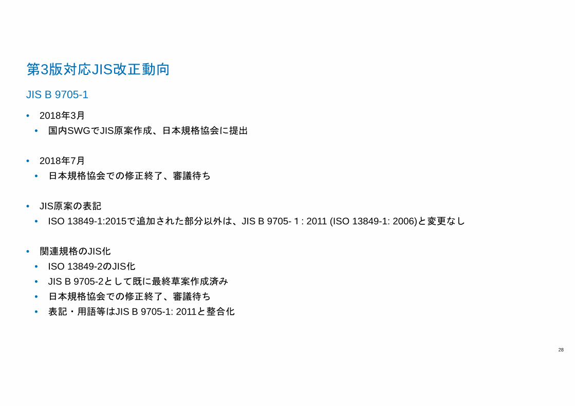
• 2018年3月
• 国内SWGでJIS原案作成、日本規格協会に提出
• 2018年7月
• 日本規格協会での修正終了、審議待ち
• JIS原案の表記
• ISO 13849-1:2015で追加された部分以外は、JIS B 9705-1: 2011 (ISO 13849-1: 2006)と変更なし
• 関連規格のJIS化
• ISO 13849-2のJIS化
• JIS B 9705-2として既に最終草案作成済み
• 日本規格協会での修正終了、審議待ち
• 表記・用語等はJIS B 9705-1: 2011と整合化
JIS B 9705-1

ご清聴ありがとうございました
お問い合わせテュフ ラインランド ジャパン株式会社テクノロジーセンター杉田 吉広〒224224224224----0021 0021 0021 0021 横浜市都筑区北⼭田4444----25252525----2222
電話: 045 914 0369: 045 914 0369: 045 914 0369: 045 914 0369
Fax: 045 914 3377Fax: 045 914 3377Fax: 045 914 3377Fax: 045 914 3377
E-mail︓ [email protected]
www.jpn.tuv.com
LEGAL DISCLAIMERThis document remains the property of TÜV Rheinland . It is supplied in confidence solely for informati on purposes for the recipient. Neither this document nor any inform ation or data contained therein may be used for any other purposes, or duplicated or disclosed in whole or in part, to any third party, without the prior written authoriza tion by TÜV Rheinland.This document is not complete without a verbal expl anation (presentation) of the content. TÜV Rheinland AG

ISO/CD 13849-1:2018(E)
© ISO 2017 – All rights reserved 13
389
Figure 2 — Schematic representation of risk reduction process including iterative three-step 390 method according to ISO 12100:2010 391

ISO/CD 13849-1:2018(E)
© ISO 2017 – All rights reserved 15
402
Figure 3 — Designing a SRP/CS in accordance with ISO 13849-1 403