fertijet - galcon public folder folder/new... · - 4 - 1. general description. fertijet is a simple...
TRANSCRIPT

USER MANUAL
- 1 -
FERTIJETUSER MANUAL


USER MANUAL
- 3 -
TABLE OF CONTENTS
GENERAL DESCRIPTION 4
1.1SystemComponents 4
1.2SafetyInstructions 4
2. INSTALLATION AND CONNECTION 5
2.1Pipes 5
2.2Cabling 8
2.3Low-PressureSwitch 10
2.4PressureoftheEC/pHSamplingCell 10
3. CONFIGURATION OF THE IRRIGATION SYSTEM 11
4. OPERATION 11
4.1AdjustmentofFertilizerInjectors 12
4.2AutomatedAdjustmentoftheFertigation 12
5. MAINTENANCE 14
5.1FertijetMaintenance 14
6. ANNEXES 15
6.1MechanicalComponents 15
6.2CablingColorCodes 15

- 4 -
1. GENERAL DESCRIPTION
Fertijetisasimpleandmodularfertigationcontrolmachine,whichisasystemwidelyusedingreenhousesandopen-fieldirrigationsystems.Fertijetisdesignedfortheaccurateon-lineinjectionofnutrientsintheirrigationwaterpipe,viaasetofVenturi-typefertilizinginjectors,controllingtheEC/pHoftheirrigationwater,operatedbytheadvancedGalileocontroller.Fertijetisrapidlyandeasilyinstalledonanyirrigationhead.
1.1. SYSTEM COMPONENTSAstandardFertijetunitconsistsofthefollowingcomponents:-Manifoldwithasetof3,4ormoreVenturi-typefertilizerinjectors,withaflowofupto1200LPHeach.EachinjectorcontainsafertilizerON/OFFcontrolelectrovalve,anadjustableflowregulatorandaflexibleaspirationtube.
-Electricwaterpump(1.5,2.5HPand10HP)withstainlesssteelhead,toobtainawaterflowthroughthefertilizerinjectors,andtoinsertthesolutioninthewaterpipes.
-EC/pHmonitoringunit,consistingofa4-20mAoutputtransmitterwithgalvanizedisolation,LCDscreenandfour-buttonkeyboardforswiftcalibration.
-ApairofpH/ECelectrodes,installedinasamplingcell.-Electriccontrolpanel,alsoincludingtheconnectionterminals.
1.2. SAFETY INSTRUCTIONS-Beforeinstallingandconnecting(pre-installation)theFertijetinyoursystem,readthemanualcarefullyandfollowallinstructionsapplicabletoFertijet.
-AvailabilityofSinglePhase/Three-PhaseElectricPowerSupply(50or60Hz,accordingtothespecificationsoftheacquiredmachine),andthepowerconnectionsshouldbecarriedoutonlybyacertifiedelectricaltechnician.
-DonotusetheFertijetbeforeensuringfullconnectiontoavalidgroundingpoint(5Ωorless).-Beforeremovingtheelectricalboxcover,turnthemainswitchoff.-BeforecarryingoutanymaintenanceworkontheElectricalPump,turnoffthemainswitch.-Fertijetisdesignedtoinjectdissolvedchemicalproducts,someofwhicharehazardouswhentouchedorinhaled;weargoggles,rubberglovesandgasmask,asneeded.
-Beforecarryingoutanymaintenanceworkontheinjectors,closeallmanualvalvesattheoutputofthefertilizertank.
-Followalllocalregulations,asapplicabletostorageandhandlingofchemicals.-Beforetryingtoremoveorinstallthewaterpipesystem,depressurizethemainpipes.

USER MANUAL
- 5 -
2. INSTALLATION AND CONNECTION2.1. PIPESFertijetoperatesbypassingthemainIrrigationLine.a.TheIrrigationsystemshouldNOTbepressurized.b.FollowthehydraulicSuctionandDischargeConnectionsoftheFertijet(accordingtoFigure01).TheFertijet’ssuctionshouldbedownstreaminthesystem,beforethepressureregulator/support,andthedischargewithminimum03metersbeforesuction.Ifmanualcontrolfiltersareavailable,itisrecommendedtoinstallthembetweenthesuctionandthedischargeoftheFertijetfertilizerunit.
MaximumrecommendedoperatingpressurefortheFertijetHFatthemainlineis50mca. MinimumrecommendedoperatingpressurefortheFertijetis25mca.(accordingtothefactoryPressostatSetPoint)
c.ConnectthefertilizersuctionVenturiscorrectly,withthediametersofthepipesappropriatefortheflowrateoftheVenturi.
Figure 1: Typical Installation

- 6 -
INSTALLATION PROCEDURE
1.UnpacktheFertijetandmountitonasolidbase.2.PhysicallyinspectforanydamagetotheelementsoftheFertijet.3.ChecktheOperatingBoxoftheFertijet,containingtheFertijet’selectricalcontrols.4.Connecttheinputandoutput(pipes)tothemainline,asshownonFigure1.5.ConnecttheBlueHose(watersamplingoftheEC/pH)totheinputmanifoldoftheVenturis,when
thesuctionofthemachineisinstalleddownstream.6.OpentheEC/pHsamplingcup,andremovethecoverofthepHsensor.Fillthewatersampling
cup,andputitbackinitsplace. Important: The pH sensor should be submerged in water at all times.7.Connectthepipesofthefertilizertankstotheinputsofthefertilizerinjectors. FertijetdefinesbydefaultInjectors#1,#2and#3(thefirstonesfromlefttoright)asNutrient
injectors(ECinjectors),whichenabletocorrecttheamountstoregulatetheelectricalconductivityoftheirrigationwater.
Injector#4iscommonlyusedasacidinjector(thisinjectormaintainsthepHstabilityintheirrigationwater).
Connectthepipestoanelectricalpump,andverifythepropercoupling.
Figure 2: Fertijet Injectors

USER MANUAL
- 7 -
8.Identifytheoperatingvoltageandfrequency(Hz)levelsoftheElectricalPump(Three-Phase110Vac,220Vac,380Vacor440Vac)andconfirmtheyareadequateforthepowernetworkofthestationwheretheFertijetwilloperate.
9.OncethevoltageleveloftheIrrigationStationhasbeenidentified,checkthe“ElectricDiagram”oftheFertijet’sElectricBoard,verifythattheoperatingvoltageisthesameasconfiguredintheFertijet’sboard(Three-Phase110Vac,220Vac,380Vacor440Vac).
Ifthevoltagelevelis the same as established in theElectricBoard,carryouttheelectricalconnectionsfromtheirrigationcontrollertotheFertijet,andothers.(SeeItem2.2Cabling)
Ifthevoltagelevelis NOT the same as established in theElectricBoard,immediatelychangetheelectricconfigurationfeedingtheinternalpowerTransformeroftheelectricboard(seeElectricalDiagram,whereasthismodificationneedstobecarriedoutbyaqualifiedTechnician);uponconfirmationoftheproperconnection,carryouttheelectricalconnectionsfromtheirrigationcontrollertotheFertijet,andothers.(SeeItem2.2Cabling)
WemustverifyproperoperationoftheElectricalPump.-FillthesuctionpipeoftheElectricalPumpwithwater(feedingoftheElectricalPump);forshort
bootingoftheelectricalpump.
10.CarryoutshortignitionsoftheElectricalPump,todeterminetheTURNINGDIRECTION(clockwise)oftherotoroftheElectricalPump.IftheturningdirectionisNOTtheappropriateone,modifyimmediatelytheorderoftheelectricalphasesfeedingtheFertijet,untilthedirectionisthecorrectone.Iftheturningdirectionistheappropriateone,youmayturnontheFertijetwithoutanytrouble.
NowtheFertijetisreadyforconfiguration,calibrationandtofertigate.

- 8 -
2.2. CABLING
Power Supply Connections1.Connectingtheelectricalpumptothepowersupply: Aqualifiedelectricianmustconnecttheloadofthebackuppump,accordingtothebrand,labelattheendofthecable(green);theelectricaldrawingsofthesystemcanbefoundonthecabinetdoor.
2.ControllerandContactConnection: Connectthecontrollerandcontactbywire(white)tothelocalgrid,viaaproperconnection(notonawalloutlet!)Verifythatthissupplypointisprotectedbya6AThree-PhaseBreaker).
1.ElectricalSupplyFeeding–Three-Phase380/440Vac.2.ElectricalSupplyOutput–Three-Phase380/440VactoELECTROPUMP.3.InputandOutputConnectionTerminalsDiscreteandAnalog.4.OvercurrentElectromagneticSwitch.5.SupplyVoltageTransformer.(Input:110/230/400/460Vac–Output:24Vac–Power:200VA.6.ElectropumpBreaker.7.Three-PhaseContactorforElectropump.8.Manual/AutomaticandSupplytoGalileoSwitch.9.AnalogSignalAdaptorCards.
Figure 3: Power Supply Connections

USER MANUAL
- 9 -
Output Connections1.OpenthecoveroftheI/OboxandidentifytheOPTNcards.Lookatthenumbersshowninthecard,asitisthenumberofoutputsthatremainfreetobeusedafterattachingtheFertijetaccessories(injectorvalves,supportpump).ConnectthepinstothefreepointsandrecordtheirconnectionsintheIDbookpage4.
Caution:Pre-establishedsettingsassignOutput1 to themainvalveandOutput2 to themainpump.Tochangethisconfiguration,forexample,forthesakeofstandardization,seeIDinthebookpage4(rightcolumn).
Discrete Input Connections1.Verifythatthewatermeterhasapulsesignal(identifythesizeofthePulse,1m3/0.5m3/0.1m3);thissensorisconnectedtothediscreteinputoftheirrigationcontroller.
2.Theenginefailureswitch(breaker)mustbeproperlyconnectedandconfiguredtotheirrigationcontroller,toenablethefollow-upofchangesinthecontactstatus.
3.Identify the terminal IPTcards in the I/Obox.Watch thenumberson thecards:Theseare theinputnumbersthatremainfreetobeusedafterattachingtheaccessoriesoftheFertijet(overload-triggeredpressurepump,lowpressureswitch).ConnectyourowndevicestothefreepointsandrecordtheirconnectionsintheIDbookpage6.
Figure 4: Input Connections
1.SupplyforEC/pHMonitor–24VacTerminals2.PRESSOSTATconnectionterminals.3.DiscreetOutputConnectionTerminals(Electrovalves).4.COMMONTerminalsforDiscreetOutputs(Electrovalves).5.ConnectionTerminalsforDiscreetInputs.6.COMMONTerminalsforDiscreetInputs.7.ConnectionTerminalsforAnalogInputs.

- 10 -
2.3. LOW-PRESSURE SWITCHFertijethasalowpressureswitch(LP–Pressostat)topreventthepumpfromoperatingunderlowwaterpressure.TheLPswitchisinitiallyasetto25 mca.
WARNING!Reducingthevaluebelow20mcaendangersyourelectricalpumpandvoids our warranty immediately.
****TochangetheconfigurationoftheLPPressostat,removethecovertoshowtwoscrewsontheupperpartoftheunit.Useonlyascrewdrivertomodifythevalueofthepressure;turnthescrewdrivertotheright/left(youwillseeametallineascendingordescendingonthescale)toincreaseordecreasethepressure.
2.4. PRESSURE OF THE EC/pH SAMPLING CELL
ThepHelectrodeisalowpressureprobe.Neverexposetheelectrodetoapressureexceeding35mca.Toadjustthepressureofthesamplingcell:FirstverifythatthemainlineispressurizedandtheelectricalpumpoftheFertijetisswitchedon.Toadjust,followtheprocedurebelow:1.Close themanualvalveat the inputof thesamplingpipe(blue).
2.Removeoneoftheelectrodesattheupperpartof thecell.
MCAPSIBARkg/cm210.0014.220.981.0020.0028.441.962.0030.0042.672.943.0040.0056.893.924.0050.0071.114.905.0060.0085.345.886.00
Figure 5: Low Pressure Pressostat

USER MANUAL
- 11 -
3.Openthemanualvalvegraduallyuntilthewaterslightlyspillsoverfromtheemptyhole.4.Reinstalltheprobebackinplace.Recommendation: Removeorbanusingthemanualvalvehandle,topreventaninadvertentadjustment.
3. CONFIGURATION OF THE IRRIGATION SYSTEMEachfertigationsystemdiffersfromtheother;theonlywaytoassureproperoperationisbyidentifyingthefollowingvariables:Sizeofthepulse/m3ofthewatermeter,flowrateofthevalves,typesandapplicationsoffertilizers.
AlltheseparametersarenecessaryfortheoperationoftheGalileo–Fertijetsystem,andcanbefoundintheGALILEOWandOPENFIELDmanual;reviewtheinformation.
4. OPERATION
ForaproperoperationoftheFertijet,werecommendtocarryoutthefollowingsteps:1. Gauging the suction flow rate of each Venturi.*Maximum suction flow rate of eachVenturi (liters/hour).Obtain the reading of the flowmeterinstalledatthesuctionofeachVenturi.Ifnoflowmeterisavailableatthesuction,thenthesuctionofeachVenturimustbegauged.
*Thevalueobtainedshouldmeetthenominalflowrateoftheinjectionunit;forexample,ifitisastandardmachinewitha350L/hVenturi,thegaugingresultshouldbeabout350liters/hour.
2. Operation of Electrovalves.*ElectricallyactivatetheelectrovalvesVerifythefullopeningandfullclosureoftheelectrovalves.Discardvibrationsofthecoiluponswitchingonthevalvesorcloggingofthevalves.
3. Operating Injection Ratio. *Verifyiftheoperatinginjectionratios(liters/m3)ofeachVenturiarewithintheinjectioncapacityoftheFertijet.(consultwithyourproviderthecapacityoftheacquiredequipment).
*TheEC/pHobjectiveshouldbe to reachan injection rationbelow themaximumallowedratio(50%ofthemaximumpermitted).Toverifythis,theappropriatequalificationsshouldbemade.
4. EC/PH Electrodes Calibration.*CleaningtheEC/pHelectrodesonaweeklybasis.Thusitisrecommendedtoremoveanyimpurityontheelectrodesfor10minuteswiththeacidsolutionpreparedintheacidtank.
*Use4.0and7.0BuffersolutionsforthepH,andthe1.4mS/cmsolutionfortheEC.*ForthepHelectrode,measurehowlongittakestheelectrodetoreachareadingof4.0to7.0.ForthisexerciseusethepH4.0and7.0solutions;whereasifthetimeelapsedexceeds30seconds,thepHelectrodeshouldbereplacedtoassurecontrol.
5. Pressure and flow rate of the irrigation shift.*Measuretheoperatingpressurewithanirrigationshift,withthefertilizationmachine.*Measurethemaximumflowrateoftheirrigationshift.

- 12 -
*Verifythattheflowrates,pressuresandflowrateandpressurevariationsattheirrigationshiftchangeare within the allowed ranges of the installed Fertijet.
Iftheflows,pressuresandflowrateandpressurevariationsattheirrigationshiftchangeareNOT within the allowed ranges of the installed Fertijet, the Fertijet will not be able to correct the EC/pH according to the customer’s requirements.
The stable flow rate variation is recommended not to exceed 15%.
4.1 ADJUSTMENT OF FERTILIZER INJECTORSEachfertilizerinjectorcomeswithanadjustableflowmeter,whichenablestoverifyandadjustthesuctionflowrateofeachVenturi,whichshouldberecordedintheOpenFieldforproperoperationoftheFertijet.
4.2 AUTOMATED ADJUSTMENT OF THE FERTIGATIONTheFertijetwillnotoperateproperlyunlessyoucorrectlydefine:*TheintakepointoftheEC/pHsample:Thisdecisionismadebythespecializedtechnicianwhoinstalledthemachine.Thispointandthelengthofthepipetothesamplingcell,significantlyinfluencetheautomationfunction.Whentheprogramchangestheinjectionratio,atimerisestablishedtodefinetheminimumtimeforthenextchange(ifnecessary).ThisfunctionenablesidentifyingassoonaspossiblethevalueandrateofthelastEC/pHmodification,ifitfails,whencarryingoutthenextchange,thechangeoftheEC/pHvalueshallbemadepriortoreadingtheresultsofthefirstone,causingafalsemeasurement(overshooting),andtheEC/pHwillneverbebalanced.Ontheotherhand,aslowreactionisnotdesirableeither.Calculatingtheshortestresponsetimeisadifficulttask,weshallusethefollowingdata:
Rt=Ht+dt+Dt+3Where: Rt: RequiredResponseTime. Ht: Bluehosesamplingtime(sec) Hl: Bluehosesamplinglength(m)Ht=Hl/0.4 dl: Lengthofthepipe(32mm)fromthewaterintakeofthemainpipetotheFertijet(m). dt: Timeinthe32-mmpipe(sec)dt=dl/13,9 SQ: Valueoftheflowinthesmallestchangeoftheirrigationsystem. D: Internaldiameterofthemainpipe-Matrix Dl: DistancebetweenthedischargepointoftheFertijetandtheintakeoftheEC/pH (cm)sample Dt: Delaytimeinthemainpipe.-> Dt=⸨(D⁄2)2*π)*Dl)) ⁄SQ

USER MANUAL
- 13 -
Figure 6: Rt Calculation
Notes- The3secondsaddedtothecalculationrepresenttheresponsetimeoftheEC/pHprobe.- "dl"issubjecttomanychangesthatcouldbecausedbythelinepressure,pumpmodel,number
and typeofVenturi, includingelectrovalves(switchedON/OFF).Nevertheless, if theFertijet isnot installedatadistanceofmore than twometers from the insertionpoint, theeffecton thecalculationwouldbenegligible.
Technical Procedure:(1)Calculatetheresponsetime(Rt).(2)Enterthecalculationresultintherelatedparameterofthecontroller."DelayBeforeMeasurement
(sec)".(3)Modifythevalueofthe“AutomationSegment(sec)”byarecommendedvalueof2.5timesthe
DelayBeforeMeasurement(sec)
- 14 -
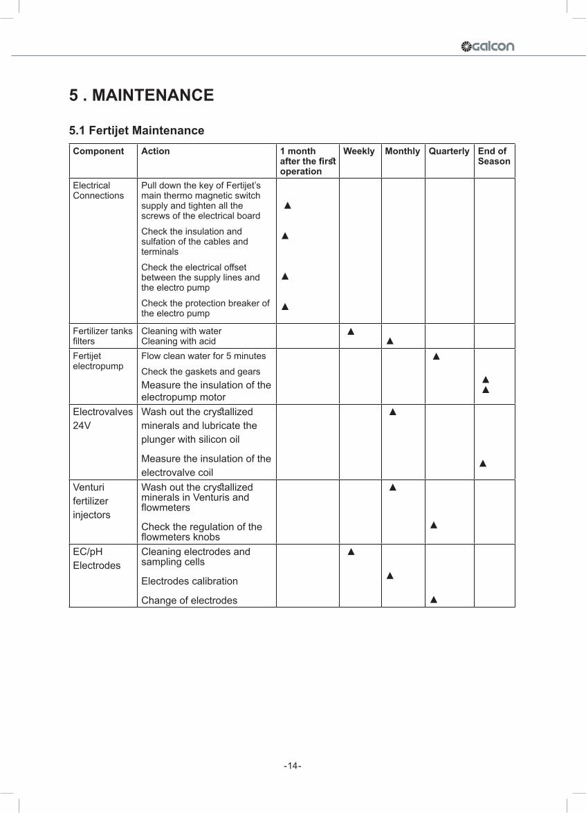
Component Action 1 month after the first operation
Weekly Monthly Quarterly End of Season
ElectricalConnections
PulldownthekeyofFertijet’smainthermomagneticswitchsupplyandtightenallthescrewsoftheelectricalboardChecktheinsulationandsulfationofthecablesandterminalsChecktheelectricaloffsetbetweenthesupplylinesandtheelectropumpChecktheprotectionbreakeroftheelectropump
▲
▲
▲
▲
Fertilizertanksfilters
CleaningwithwaterCleaningwithacid
▲ ▲
Fertijetelectropump
Flowcleanwaterfor5minutesCheckthegasketsandgearsMeasuretheinsulationoftheelectropumpmotor
▲
▲▲
Electrovalves24V
Washoutthecrystallizedmineralsandlubricatetheplungerwithsiliconoil
Measuretheinsulationoftheelectrovalvecoil
▲
▲
Venturifertilizerinjectors
WashoutthecrystallizedmineralsinVenturisandflowmeters
Checktheregulationoftheflowmetersknobs
▲
▲
EC/pHElectrodes
Cleaningelectrodesandsamplingcells
Electrodescalibration
Changeofelectrodes
▲
▲
▲
5 . MAINTENANCE
5.1 Fertijet Maintenance

USER MANUAL
- 15 -
6. ANNEXES
6.1. Mechanical Components:
6.2. Cabling Color Codes
CABLING COLORS CODE
Analog InputsAN.COM Black
EC Black/RedPH White
OutputsCOMOUT BlueFERT.1 RedFERT.2 OrangeFERT.3 YellowFERT.4 White/RedFERT.5 White/Green
MAINFERT. Green
InputsCOMIN Purple
COUNTER1COUNTER2 Black/GreyCOUNTER3 Black/BrownCOUNTER4 Black/PurpleCOUNTER5 Black/WhitePUMPFAULT Grey
1.¾”Elbow2.Checkvalve+record3.Trans.femaleconn.¾”>½”4.CompleteSiraivalve50Hz5.CompleteSiraivalve60Hz6.Adjustable½”valve7.Pipeconnection8.Siraicoil~24V50Hz9.Diaphragm(New)10.Siraivalvehousing11.Distributormanifold4outlets12.Venturiinjectorskeleton350l/h(90GPH)13.Mixingmanifold4inlets14.Boosterpumpinletadaptor(800series)14.Boosterpumpinletadaptor(400series)15.Water+fertilizeroutletfitting(800series)15.Water+fertilizeroutletfitting(400series)16.Flexiblepipefitting32mm»1½”17.Mechanicalbearing16mm18.Boosterpump~3440V50/60Hz2.5,5.00,10.00HP

Cat.No:AT1022.01