fences · bs 1722-2:2006 ii • foreword publishing information this part of bs 1722 was published...
TRANSCRIPT
BS 1722-2:2006
Fences –Part 2: Specification for strained wire and wire mesh netting fencesICS 91.090
NO COPYING WITHOUT BSI PERMISSION EXCEPT AS PERMITTED BY COPYRIGHT LAW
BRITISH STANDARD
Incorporating Corrigendum No. 1
Confirmed December 2011
Publishing and copyright informationThe BSI copyright notice displayed in this document indicates when the document was last issued.
© BSI 2010
ISBN 978 0 580 72022 2
The following BSI references relate to the work on this standard:Committee reference B/201Draft for comment 06/30139497 DC
Publication historyFirst published March 1951Second edition April 1963Third edition October 1973Fourth edition September 1989Fifth edition (incorporating BS 1722-3:1986) April 2000Sixth (present) edition November 2006
Amendments issued since publication
Amd. no. Date Text affected
BS 1722-2:2006
Corr. 1 31 August 2010 See Foreword
© BSI 2010 • i
BS 1722-2:2006
ContentsForeword ii
1 Scope 12 Normative references 13 Terms and definitions 34 Materials for general pattern strained wire fences 45 Installation of general pattern strained wire fences 126 Materials for dropper pattern fences 157 Installation of dropper pattern fences 178 Materials for general pattern wire mesh fences
[see Figure 3d)] 199 Installation of general pattern wire mesh fences 26
10 Materials for spring steel and high tensile mesh fences 3011 Installation of spring steel and high tensile mesh fences 3112 Statement of conformity 35
AnnexesAnnex A (normative) Concrete components 37Annex B (normative) Steel components and protective treatment 39Annex C (informative) Specifying a strained wire fence 41Annex D (normative) Method of measuring line wire tension 44Annex E (informative) Determination of moisture content 45
Bibliography 46
List of figuresFigure 1 – General characteristics of strained wire fences 3Figure 2 – Typical wire fittings 20Figure 3 – General characteristics of wire mesh netting fences 23Figure 4 – Suitable method of joining rectangular mesh 27Figure 5 – Relative positions of posts and line wires at changes of direction of spring steel fence line 33Figure 6 – Suitable methods of tying horizontal wires 35Figure D.1 – Wire tension gauge 44
List of tablesTable 1 – General requirements for strained wire fences 4Table 2 – Dimensions of concrete fence posts and struts 6Table 3 – Dimensions of steel fence posts and struts 10Table 4 – Sawn timber fence posts and struts 11Table 5 – Round timber fence posts and struts 11Table 6 – Types, applications and dimensions of strained wire and wiremesh netting fences 21Table 7 – Mesh sizes, wire diameters with widths of hexagonal wire netting 22Table 8 – Concrete fences, posts and struts for general pattern fences 26Table B.1 – Recommended steel grades 40Table E.1 – Determination of moisture content of timber to be treated for use in fencing 45
Summary of pages
This document comprises a front cover, an inside front cover, pages i to iv, pages 1 to 46, an inside back cover and a back cover.
BS 1722-2:2006
ii •
ForewordPublishing informationThis part of BS 1722 was published by BSI and came into effect on 30 November 2006. It was prepared by Technical Committee B/201, Fences. A list of organizations represented on this committee can be obtained on request to its secretary.
SupersessionThis part of BS 1722 supersedes BS 1722-2:2000, which is withdrawn.
Relationship with other publicationsBS 1722 is published in the following parts:
• Part 1: Specification for chain link fences;
• Part 2: Specification for strained wire and wire mesh netting fences;
• Part 4: Specification for cleft chestnut pale fences;
• Part 5: Specification for close-boarded and wooden palisade fences;
• Part 7: Specification for wooden post and rail fences;
• Part 8: Specification for mild steel (low carbon steel)continuous bar fences and hurdles;
• Part 9: Specification for mild steel (low carbon steel) fences with round or square verticals and flat horizontals;
• Part 10: Specification for anti-intruder fences in chain link and welded mesh;
• Part 11: Specification for woven wood and lap boarded panel fences;
• Part 12: Specification for steel palisade fences;
• Part 13: Chain link fences for tennis court surrounds;1)
• Part 14: Specification for open mesh steel panel fences;
• Part 16: Specification for organic powder coatings for use as a plastics finish to components and mesh;
• Part 17: Specification for electric security fences – Design, installation and maintenance;
• Part 18: Specification for steel mesh site perimeter temporary fencing systems.2)
Information about this document
It should be noted that no attempt has been made to standardize fences or gates of a purely decorative nature, or those to suit special requirements; or to specify requirements for “patent” proprietary fencing systems. However, such fences or gates should be designed in accordance with the relevant clauses of this part of BS 1722.
1) Obsolescent.2) Part 18 is in development and will be published as a Draft for Development
(DD).
The start and finish of text introduced or altered by Corrigendum No. 1
is indicated in the text by tags .PQ
© BSI 2010
• iii
BS 1722-2:2006
This standard aims to establish minimum requirements for materials and workmanship for the more common types of fence in order toensure satisfactory service for the purchaser, and to assist manufacturers and installers by eliminating unnecessary minor variations in the demands of purchasers. It specifies requirements for the components that make up a fence and the way in which the fence needs to be constructed.
The standard includes requirements for sizes of components, together with the permissible tolerances on size. These are minimum requirements and it is normally acceptable to use larger sizes, except if this could adversely affect the fitting of components or if replacement parts are required to match up with those already present.
Choosing a suitable fence is affected by factors such as intended purpose, desired service life, aesthetic considerations and availability ofcomponents. The specifier can match a suitable choice of fence to its intended purpose and also inform those installing the fence of the basic characteristics required. Premature failure of the fence can be avoided by taking care not to overstrain coated wire or to damage protective treatments during installation.
Ground conditions might indicate that a variation in the length of a postor strut, or the depth, to which it should be set, is desirable. The posts and struts and setting depths specified in this standard are intended for use in normal ground conditions, but if special conditions exist that warrant a change in the specification, e.g. the ground is softer or firmer than usual, such a change should be agreed with the specifier.
Annex A specifies requirements for concrete components.
Annex B specifies requirements for steel components.
Annex C provides details of the fence requirements and installation site that should be agreed between the fence supplier and purchaser.
NOTE Conditions vary from site to site. Annex B should not be assumed to be exhaustive.
Annex D specifies a method of measuring line wire tension.
Annex E provides guidance on the determination of water content.
Use of this documentIt has been assumed in the drafting of this part of BS 1722 that the execution of its provision is entrusted to appropriately qualified and experienced people. Before installation commences the Lead Installer should hold a current FISS/CSCS registration card skilled level (blue card) or equivalent and all other operatives should hold the basic fence operative card (green card) or equivalent.
At the time of publication of this British Standard the registration cards are validated by the Joint Fencing Industry Skills Scheme (FISS) and Construction Scheme Skills Certification Scheme (CSCS). FISS/CSCSmaintains a national register of fence installers and operatives. There might be other schemes available.
© BSI 2010
BS 1722-2:2006
iv •
Presentational conventionsThe provisions of this standard are presented in roman (i.e. upright) type. Its requirements are expressed in sentences in which the principal auxiliary verb is “shall”.
Commentary, explanation and general informative material is presented in smaller italic type, and does not constitute a normative element.
Requirements in this standard are drafted in accordance with The BSI guide to standardization – Section 2: Rules for the structure, drafting and presentation of British Standards, subclause 11.3.1, which states, “Requirements should be expressed using wording such as: ‘When tested as described in Annex A, the product shall ...’”. This means that only those products that are capable of passing the specified test will be deemed to conform to this standard.
Contractual and legal considerationsThis publication does not purport to include all the necessary provisions of a contract. Users are responsible for its correct application.
Compliance with a British Standard cannot confer immunity from legal obligations.
© BSI 2010
• 1
BS 1722-2:2006
1 ScopeThis part of BS 1722 specifies requirements for the construction and installation of general pattern and dropper pattern strained wire fences and rectangular wire mesh fences, including mild steel or high tensile woven wire fencing, welded mesh fencing, hexagonal wire netting fences of the general pattern, and spring steel wire pattern fences where the mesh is fixed onto spring steel line wires.
This standard includes requirements for protective treatments. However, maintenance requirements of the fence after installation are outside the scope of this standard.
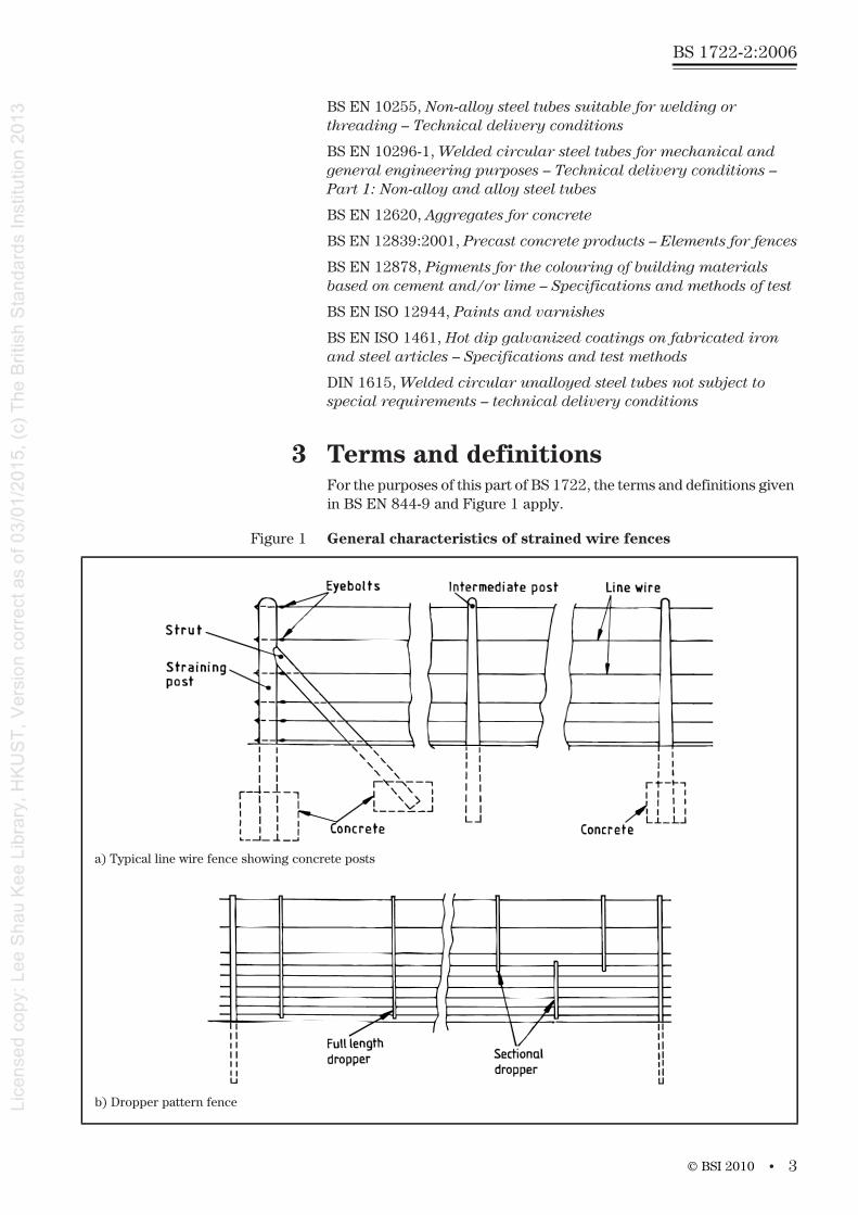
NOTE Figure 1 illustrates the general characteristics of strained wire fences. It is not intended to illustrate any particular requirements of this standard but provides guidance as to the general layout of a typical fence, and on the terminology associated with this form of fencing.
2 Normative referencesThe following referenced documents are indispensable for the application of this document. For dated references, only the edition cited applies. For undated references, the latest edition of the referenced document (including any amendments) applies.
BS 1202-1, Specification for nails – Part 1: Steel nails
BS 1722, Fences
BS 1722-4, Fences – Part 4: Specification for cleft chestnut pale fences
BS 1722-7, Fences – Part 7: Specification for wooden post and rail fences
BS 1722-16, Fences – Part 16: Specification for organic powder coatings to be used as a plastics finish to components and mesh
BS 3892, Pulverized-fuel ash
BS 4027, Specification for sulfate-resisting Portland cement
BS 4102, Specification for steel wire for general fencing purposes
BS 4320, Specification for metal washers for general engineering purposes – Metric series
BS 4449, Steel for the reinforcement of concrete – Weldablereinforcing steel – Bar, coil and decoiled product – Specification
BS 4482, Steel wire for the reinforcement of concrete products – Specification
BS 4483, Steel fabric for the reinforcement of concrete – Specification
BS 4652, Specification for zinc-rich priming paint (organic media)
BS 8500-1:2002, Concrete – Complementary British Standard to BS EN 206-1 – Part 1: Method of specifying and guidance for the specifier
BS 8500-2:2002, Concrete – Complementary British Standard to BS EN 206-1 – Part 2: Specification for constituent materials and concrete
© BSI 2010
BS 1722-2:2006
2 •
BS EN 197-1, Cement – Part 1: Composition, specifications and conformity criteria for common cements
BS EN 206-1:2000, Concrete – Part 1: Specification, performance,production and conformity
BS EN 212, Wood preservatives – General guidance on sampling and preparation for analysis of wood preservatives and treated timber
BS EN 287-1, Qualification test of welders – Fusion welding – Part 1: Steels
BS EN 480, Admixtures for concrete, mortar and grout – Test methods
BS EN 844-9, Round and sawn timber – Terminology – Part 9: Terms relating to features of sawn timber
BS EN 934, Admixtures for concrete, mortar and grout
BS EN 10025-2, Hot rolled products of structural steels – Part 2: Technical delivery conditions for non-alloy structural steels
BS EN 10056-1, Specification for structural steel equal and unequal angles – Part 1: Dimensions
BS EN 1011-1, Welding – Recommendations for welding of metallic materials – Part 1: General guidance for arc welding
BS EN 1011-2, Welding – Recommendations for welding of metallic materials – Part 2: Arc welding of ferritic steels
BS EN 10210-1, Hot finished structural hollow sections of non-alloyand fine grain steels – Part 1: Technical delivery requirements
BS EN 10210-2, Hot finished structural hollow sections of non-alloyand fine grain steels – Part 2: Tolerances, dimensions and sectional properties
BS EN 10219-1, Cold formed welded structural hollow sections of non-alloy and fine grain steels – Part 1: Technical deliveryrequirements
BS EN 10219-2, Cold formed welded structural hollow sections of non-alloy and fine grain steels – Part 2: Tolerances, dimensions and sectional properties
BS EN 10223, Steel wire and wire products for fences
BS EN 10223-1, Steel wire and wire products for fences – Part 1: Zinc and zinc alloy coated steel barbed wire
BS EN 10223-2, Steel wire and wire products for fences – Part 2: Hexagonal steel wire netting for agricultural, insulationand fencing purposes
BS EN 10223-5, Steel wire and wire products for fences – Part 5: Steel wire woven hinged joint and knotted mesh fencing
BS EN 10240, Internal and/or external protective coatings for steel tubes – Specification for hot dip galvanized coatings applied in automatic plants
BS EN 10244-2, Steel wire and wire products – Non-ferrous metallic coatings on steel wire – Part 2: Zinc or zinc alloy coatings
© BSI 2010
• 3
BS 1722-2:2006
BS EN 10255, Non-alloy steel tubes suitable for welding or threading – Technical delivery conditions
BS EN 10296-1, Welded circular steel tubes for mechanical and general engineering purposes – Technical delivery conditions – Part 1: Non-alloy and alloy steel tubes
BS EN 12620, Aggregates for concrete
BS EN 12839:2001, Precast concrete products – Elements for fences
BS EN 12878, Pigments for the colouring of building materials based on cement and/or lime – Specifications and methods of test
BS EN ISO 12944, Paints and varnishes
BS EN ISO 1461, Hot dip galvanized coatings on fabricated iron and steel articles – Specifications and test methods
DIN 1615, Welded circular unalloyed steel tubes not subject tospecial requirements – technical delivery conditions
3 Terms and definitionsFor the purposes of this part of BS 1722, the terms and definitions given in BS EN 844-9 and Figure 1 apply.
Figure 1 General characteristics of strained wire fences
a) Typical line wire fence showing concrete posts
b) Dropper pattern fence
© BSI 2010
BS 1722-2:2006
4 •
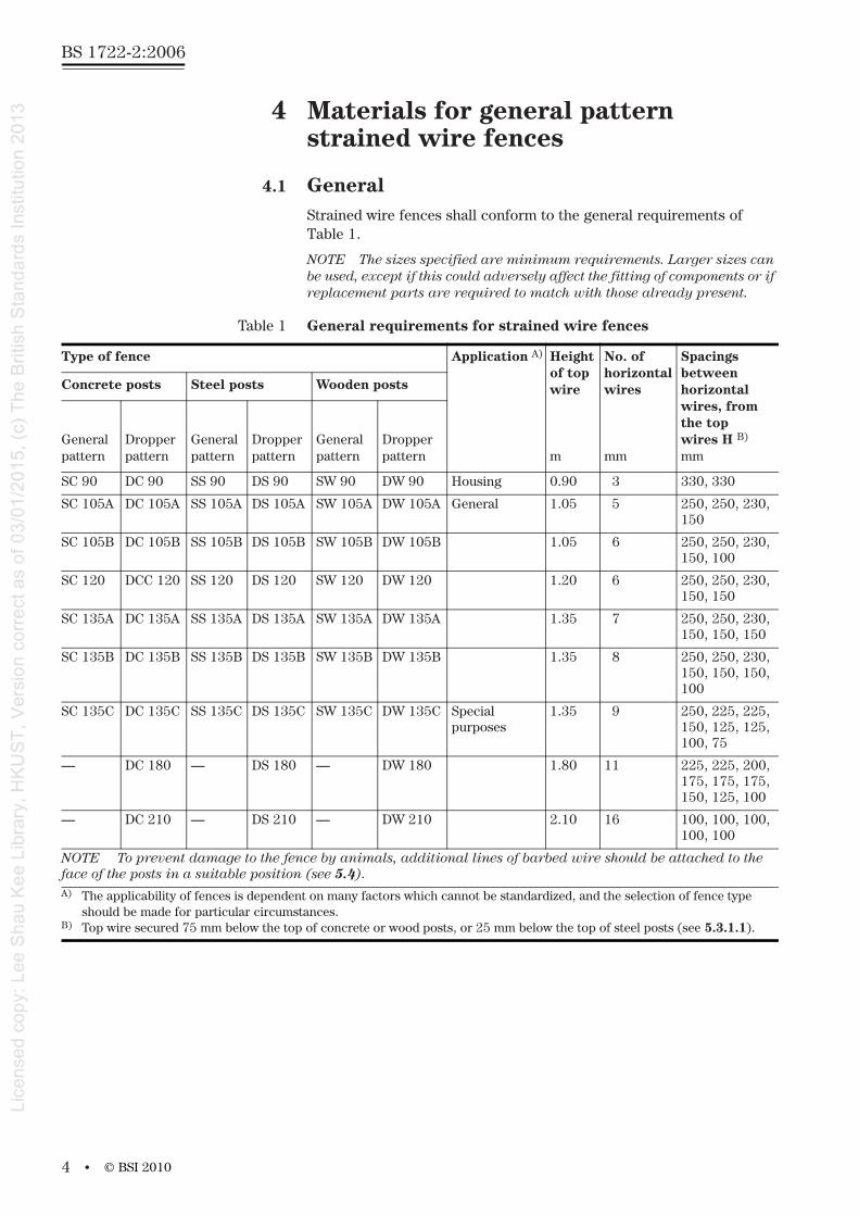
4 Materials for general pattern strained wire fences
4.1 GeneralStrained wire fences shall conform to the general requirements of Table 1.
NOTE The sizes specified are minimum requirements. Larger sizes can be used, except if this could adversely affect the fitting of components or if replacement parts are required to match with those already present.
Table 1 General requirements for strained wire fences
Type of fence Application A) Height of topwire
m
No. of horizontal wires
mm
Spacings between horizontal wires, from the top wires H B)
mm
Concrete posts Steel posts Wooden posts
General pattern
Dropper pattern
General pattern
Dropperpattern
General pattern
Dropperpattern
SC 90 DC 90 SS 90 DS 90 SW 90 DW 90 Housing 0.90 3 330, 330
SC 105A DC 105A SS 105A DS 105A SW 105A DW 105A General 1.05 5 250, 250, 230,150
SC 105B DC 105B SS 105B DS 105B SW 105B DW 105B 1.05 6 250, 250, 230,150, 100
SC 120 DCC 120 SS 120 DS 120 SW 120 DW 120 1.20 6 250, 250, 230,150, 150
SC 135A DC 135A SS 135A DS 135A SW 135A DW 135A 1.35 7 250, 250, 230,150, 150, 150
SC 135B DC 135B SS 135B DS 135B SW 135B DW 135B 1.35 8 250, 250, 230,150, 150, 150,100
SC 135C DC 135C SS 135C DS 135C SW 135C DW 135C Special purposes
1.35 9 250, 225, 225,150, 125, 125,100, 75
— DC 180 — DS 180 — DW 180 1.80 11 225, 225, 200,175, 175, 175,150, 125, 100
— DC 210 — DS 210 — DW 210 2.10 16 100, 100, 100,100, 100
NOTE To prevent damage to the fence by animals, additional lines of barbed wire should be attached to the face of the posts in a suitable position (see 5.4).A) The applicability of fences is dependent on many factors which cannot be standardized, and the selection of fence type
should be made for particular circumstances.B) Top wire secured 75 mm below the top of concrete or wood posts, or 25 mm below the top of steel posts (see 5.3.1.1).
© BSI 2010
• 5
BS 1722-2:2006
4.2 WireNOTE Wire fittings are described in 4.6.
Wire shall conform to BS EN 10223 or BS 4102 and shall be one of the following:
a) zinc or zinc coated alloy wire with nominal wire diameterof 4.0 mm, 4.5 mm or 5.0 mm;
b) zinc or zinc alloy coated high tensile wire with nominal wirediameter of 2.5 mm, 2.55 mm or 3.15 mm;
c) organics coated high tensile wire with a zinc or zinc alloy coatedcore diameter of 3.15 mm and a 4.00 mm overall diameter.
Galvanized stirrup wire shall be of low carbon steel (mild steel) and shall have a nominal wire diameter of 2.5 mm. Organics coated stirrup wireshall have a nominal core diameter of 2.5 mm and a nominal outside diameter of 3.55 mm.
Barbed wire shall conform to BS EN 10223-1.
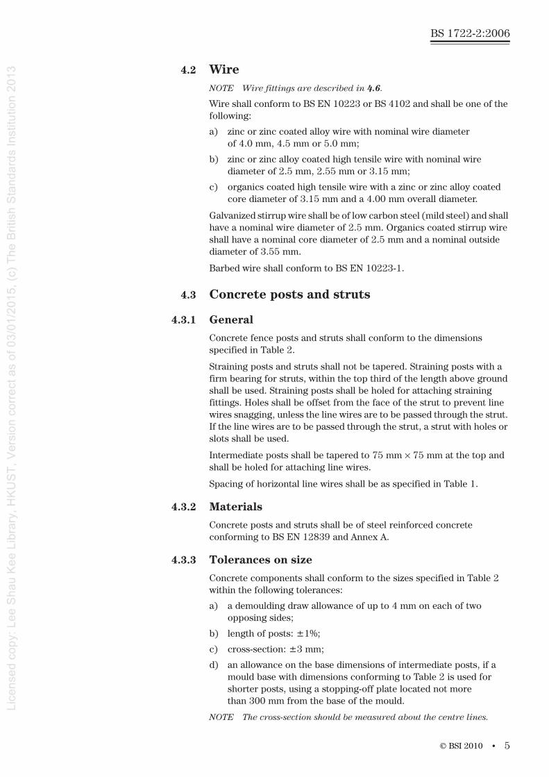
4.3 Concrete posts and struts
4.3.1 General
Concrete fence posts and struts shall conform to the dimensions specified in Table 2.
Straining posts and struts shall not be tapered. Straining posts with a firm bearing for struts, within the top third of the length above ground shall be used. Straining posts shall be holed for attaching straining fittings. Holes shall be offset from the face of the strut to prevent linewires snagging, unless the line wires are to be passed through the strut. If the line wires are to be passed through the strut, a strut with holes orslots shall be used.
Intermediate posts shall be tapered to 75 mm × 75 mm at the top and shall be holed for attaching line wires.
Spacing of horizontal line wires shall be as specified in Table 1.
4.3.2 Materials
Concrete posts and struts shall be of steel reinforced concrete conforming to BS EN 12839 and Annex A.
4.3.3 Tolerances on size
Concrete components shall conform to the sizes specified in Table 2 within the following tolerances:
a) a demoulding draw allowance of up to 4 mm on each of two opposing sides;
b) length of posts: ±1%;
c) cross-section: ±3 mm;
d) an allowance on the base dimensions of intermediate posts, if a mould base with dimensions conforming to Table 2 is used for shorter posts, using a stopping-off plate located not more than 300 mm from the base of the mould.
NOTE The cross-section should be measured about the centre lines.
© BSI 2010
BS 1722-2:2006
6 •
4.3.4 General construction
Posts shall be holed to the appropriate size to allow the fixing of line wires, etc. of the dimensions specified in 4.2. The hole for the top line wire shall be approximately 75 mm below the top of the post (excluding any extension for barbed wire). Holes for bolts shall allow the bolt to be freely inserted. Holes for wire shall allow a nominal 6 mm diameter bolt to be freely inserted. All holes shall be free from obstructions and accurately positioned within ±5 mm.
The long arrises formed in the base of the mould of the post shall either be rounded or all their sharp edges shall be removed. The arrises formed at the top of the mould shall be free from overfill.
The heads of posts shall be either weathered or half rounded in order toprevent lodgement of water.
4.4 Steel posts and struts NOTE See 4.6 for steel fittings.
4.4.1 Materials and protective treatment
Steel grades for posts, struts, base plates and caps, and requirements on corrosion protective treatments that can be applied, shall be inaccordance with Annex B.
4.4.2 Tolerances on size
Steel components shall conform to the sizes specified, within the following tolerances:
a) an allowance on length of ±10 mm;
b) an allowance on cross-section as specified in the applicable material standards (see Table B.1).
Table 2 Dimensions of concrete fence posts and struts
Fence heighttype
m
Intermediate posts Straining posts Struts A)
Lengthm
Base dimensionsmm
Lengthm
Sectionmm
Length (approx) m
Sectionmm
0.90 1.57 100 × 100 1.57 100 × 100 or125 × 125
1.50 75 × 75 or100 × 75 B)
1.05 1.72 — 1.87 125 × 125 1.83 100 × 75
1.20 1.87 125 × 125 2.02 — 1.98 —
1.35A and B 2.02 — 2.17 — 2.13 —
1.35C 2.17 — 2.32 150 × 150 2.13 —
1.80 2.62 — 2.77 200 × 200 2.73 100 × 100
2.10 2.92 — 3.07 — 3.03 —A) These lengths are suitable for struts fixed at an angle of 45° on level ground. If site conditions make use of struts of
these lengths unsuitable, the length should be specified.B) The larger section is for use with high tensile or spring steel line wires.
© BSI 2010
• 7
BS 1722-2:2006
4.4.3 General construction
Steel components shall be free from sharp edges and burrs. The tops ofall hollow steel posts shall be capped.
Posts shall be holed for the attachment of line wires, etc. as specified in 4.4.4. Holes for the top line wire shall be 25 mm below the top of the post. All holes shall be free from obstructions.
4.4.4 Fence posts and strutsNOTE 1 The recommended dimensions for steel posts and struts produced from rolled steel angle, round tube and rectangular or round hollow sections are given in Table 3.
NOTE 2 The use of thicker walls than those shown in the table for both posts and struts is permissible, if agreed between purchaser and supplier.
NOTE 3 Alternative section sizes to those shown given in Table 3,(e.g. 38 mm/44.5 mm or 51 mm OD circular) can be used in appropriate cases, if agreed between purchaser and supplier.
Straining posts and struts shall either be fitted with base plates (see 4.4.5) or have spragged ends. Straining posts and struts shall be holed for bolting together with an 8 mm bolt within the top third of the length of the straining post above the ground level. In addition, straining posts shall be holed to allow the attachment of straining fittings.
Intermediate posts shall have spragged or dowelled ends as appropriate or shall be fitted with base plates, or be pointed for driving into the ground. Intermediate posts shall be holed to allow the attachment of the top and bottom horizontal wires, and at least one intermediate horizontal wire.
4.4.5 Base plates and dowels
Base plates shall have a minimum specified thickness of 3 mm and shall be bolted or welded to posts. Welded base plates shall be welded in two places and for a length not less than 50% of the sum of the external faces of the posts or struts. Base plates for steel straining posts andstruts shall project at least 50 mm all round the post. Base plates for steel intermediate posts shall project at least 40 mm from at least one external face of a post. Dowels shall be of steel and shall be of at least 10 mm in diameter.
Dowels shall be driven through the post within 250 mm of the base of the post and shall project at least 50 mm from either side of the post.
4.4.6 Welding
All welding operations shall be carried out in accordance with BS EN 1011-1 and BS EN 1011-2, by suitable personnel qualified in accordance with BS EN 287-1.
© BSI 2010
BS 1722-2:2006
8 •
4.5 Timber posts and struts
4.5.1 Materials
Timber posts and struts shall be of square sawn timber or round timber conforming to BS 1722-7.
4.5.2 Tolerances on size
Timber components shall conform to the sizes specified in Tables 4 and 5 within the following tolerances:
a) an allowance on size of 1% reduction for every 5% of moisture content below 28%;
NOTE The sizes specified in Tables 4 and 5 are for timber with a moisture content of 28% determined in accordance with Annex E.
b) an allowance on length of posts of ±50 mm;
c) an allowance on other dimensions of:
1) sawn timber (see Table 4): under 75 mm: ±3 mm;
75 mm and over: ±6 mm.
2) round timber (see Table 5): ±3 mm on diameters under 75 mm;
±6 mm on diameters of 75 mm and over.
4.5.3 Timber fence posts and struts
Timber fence posts and struts shall conform to the dimensions specified in Tables 4 and 5. Sawn fence posts and struts shall have a singlecross-section throughout. Round fence posts and struts shall be sufficiently straight to provide at least one face to which wires can befixed.
Straining posts and struts shall be cut square across their base. Straining posts shall be notched for struts at a point within one half and two thirds up the straining post measured above the ground level. Intermediate posts shall either be cut square across or shall be pointedfor driving.
4.6 Fittings
4.6.1 Eyebolt strainers
Eyebolt strainers shall consist of 250 mm long bolts of at least 9.5 mm diameter and with a welded eye at one end. They shall be threaded and fitted with nuts and washers. Two-way eye bolt strainers shall be fitted with ring nuts. Eyebolt strainers and cleats shall be hot dip galvanized in accordance with BS EN ISO 1461.
© BSI 2010

• 9
BS 1722-2:2006
4.6.2 Winding brackets
Winding brackets intended for attachment to a post shall be of mild steel, flat and at least 25 mm × 3 mm. Winding brackets shall have a 12 mm minimum diameter winding bolt with a friction type ferrule or ratchet winder.
Each winding bracket shall have one fixing bolt, provided with two nuts and one washer, which can be either:
a) an eye bolt of 9.5 mm minimum diameter with a welded eye; or
b) a bolt of 10 mm diameter, with a ring nut when for use at intermediate straining posts; or
c) a tubular bolt threaded at both ends.
Wire winding fittings for use in-line with line wires or barbed wire shall be manufactured from mild steel, flat, not less than 45 mm × 2 mm diameter and shall be fitted with a winder bolt of 2 mm diameter with a friction type ferrule or ratchet winder. One end of the winding bracketshall be provided with a hole for the attachment of a line of wire.
Winding brackets, fixing bolts and nuts shall be hot dip galvanized in accordance with BS EN ISO 1461.
© BSI 2010
10 •
BS 1722-2:2006Ta
ble
3D
imen
sion
sof
ste
el f
ence
pos
ts a
nd
stru
ts
Fen
cehe
ight
m
Inte
rmed
iate
pos
tsS
trai
nin
g po
sts
Str
uts
A)
Len
gth
m
Sec
tion
Len
gth
m
Sec
tion
Len
gth
m
Sec
tion
Rol
led
stee
l an
gle
mm
Cir
cula
r ho
llow
se
ctio
nm
m
Rec
tan
gula
rho
llow
sect
ion
mm
Rol
led
stee
l an
gle
mm
Cir
cula
r ho
llow
se
ctio
nm
m
Rec
tan
gula
rho
llow
se
ctio
nm
m
Rol
led
stee
l an
gle
mm
Cir
cula
rho
llow
sect
ion
mm
Rec
tan
gula
rho
llow
se
ctio
nm
m
0.90
1.52
40×
40×
533
.7 ×
2.6
20 ×
25
× 2.
51.
5250
× 5
0×
548
.3 ×
3.2
50×
50×
41.
5240
× 4
0 ×
526
.9×
3.2
25×
25×
2.5
1.05
1.67
45×
45×
542
.4 ×
2.6
40 ×
40
× 3
1.82
60 ×
60
× 8
76.1
× 3
.260
× 60
×34
1.67
45 ×
45
× 5
42.4
×3 3
.240
× 4
0×
3
1.20
1.82
1.97
1.82
1.35
1.97
2.27
1.97
1.8
2.57
50 ×
50
× 6
48.3
× 3
.250
× 5
0×
380
× 8
0×
101 1
4.3
× 3.
610
0×3
50
× 4
2.72
B)
50 ×
50
× 6
60.3
× 3.
2
2.1
2.87
2.72
3.02
C)
60 ×
60
× 6
60.3
× 3.
2A
)T
hese
leng
ths
are
suit
able
for
stru
ts fi
xed
at a
n an
gle
of 4
5° o
n le
vel g
roun
d. If
sit
e co
ndit
ions
mak
e th
e us
e of
str
uts
of th
ese
leng
ths
unsu
itab
le, t
he le
ngth
sho
uld
be s
peci
fied
.B
)St
rain
ing
post
s an
d st
ruts
not
set
in c
oncr
ete
shal
l be
incr
ease
d in
leng
th b
y 30
0 m
m a
nd p
osts
sha
ll be
set
300
mm
dee
per
in t
he g
roun
d.C
)D
oubl
ed s
trut
s sh
all b
e us
ed w
ith
drop
per
patt
ern
fenc
es.
© BSI 2010
• 11
BS 1722-2:2006
4.6.3 Staples
Hair-pin staples shall be of round wire at least 3 mm in diameter, or sectional wire with the same cross-sectional area, with a zinc coating conforming to BS EN 10244-2. Staples for timber posts shall be 40 mm × 4 mm of round or sectional wire with a zinc coating conforming to BS EN ISO 1461.
Table 4 Sawn timber fence posts and struts
Fenceheight
m
Intermediate posts Straining posts Struts A)
Lengthm
Sectionmm
Lengthm
Sectionmm
Lengthm
Sectionmm
0.90 1.57 75 × 75 1.5 or 1.8 C)
100 × 100 or 125 × 125 D)
1.57 75 × 75
1.05 1.8 1.8 1.8
1.20 1.8 100 × 100 2.1 125 × 125 2.1 100 × 100 or100 × 50 (twin)1.35 A), B) 2.1 2.1 2.1
1.35 C) 2.1 2.4 2.1
1.80 2.7 2.7 150 × 150 2.7
2.10 3 3 3A) These lengths are suitable for struts fixed at an angle of 45° on level ground. If site conditions make the use of struts of
these lengths unsuitable, the length might need to be specified.B) When not set in concrete the lengths of straining posts and struts shall be increased by 300 mm and posts set 300 mm
deeper in the ground.C) The longer length is for use with high tensile line wire.D) The larger section is for use with high tensile line wire.
Table 5 Round timber fence posts and struts
Fenceheight
m
Intermediate posts Straining posts Struts A)
Length
m
Top (min)
mm
Length B)
m
Top diameter(min)mm
Length B)
(approx.)m
Top diameter C)
(min)mm
0.90 1.5 65 1.5 or 1.8 D) 100 or 125 E) 1.5 65
1.05 1.8 1.8 1.8
1.20 1.8 75 2.1 125 2.1
1.35 A), B) 2.1 2.1 2.1 or 100
1.35 C) 2.1 2.4 2.1
1.80 2.7 2.7 2.7
2.10 3 3 150 3A) These lengths are suitable for struts fixed at an angle of 45° on level ground. If site conditions make the use of struts of
these lengths unsuitable, the length should be specified.B) When not set in concrete the lengths of straining posts and struts shall be increased by 300 mm and posts
set 300 mm deeper in the ground.C) Dimensions are under bark measurements. If cleft or quartered timber is used, this is the diameter of a circle that fits
inside all parts of the perimeter of the top of the post or strut.D) The longer length is for use with high tensile line wire.E) The larger section is for use with high tensile line wire.
P
Q
P
Q
© BSI 2010
75
BS 1722-2:2006
12 •
4.6.4 Wire connectors
Line wires joined at mid-span shall be joined so that normal tension can be applied to the wire.
NOTE It is essential that connectors are designed to match the diameterand type of line wire used. Knots should not be used since they reduce significantly the strength of the wire, i.e. they reduce the breaking strengthof the line wire.
4.6.5 Nails, bolts, nuts and washers
Nails shall be round plain head nails conforming to BS 1202-1. Washers shall conform to BS 4320. Bolts, nuts, washers and nails shall conform to BS EN ISO 1461.
4.7 Concrete surrounding bases of posts and struts Concrete for bedding posts and struts shall be at least one part cementto ten parts 20 mm all in ballast to BS EN 12620 mixed with the minimum requisite quantity of clean water, or grade C8/10 or ST2 concrete to BS 8500-1:2002 and BS 8500-2:2002. The concrete shall be placed in position before commencement of the initial set.
5 Installation of general pattern strained wire fences
5.1 Level The top of the fence shall follow approximately the level of the ground along the length of the fence.
NOTE Unless specified (see Annex C), the installation of the fence does not include cutting or filling the ground to vary levels.
The presence of any electricity, gas, water or other undergroundservices shall be established prior to commencement of excavation, drilling or erection in the working area.
5.2 Posts and struts
5.2.1 General
Bedding holes for posts and struts shall have vertical sides.
NOTE 1 The sides of a strut hole adjacent to a post can be sloped in the direction of the line of the fence.
NOTE 2 It is realized that the ground at the top of a hole is damaged during digging. This is acceptable provided that the damage is limited tothe top of the hole and does not extend down such that the hole itself istapered out towards the top.
Bedding holes for fence posts and struts set in rammed backfill only shall be as small as is practical to allow for refilling and ramming. Holes for concrete posts and steel posts with spragged or dowelled ends shall,after installation, be filled to at least two-thirds with concrete, with thorough ramming and topped with backfill. Backfill shall be well rammed before initial setting of the concrete.
© BSI 2010
• 13
BS 1722-2:2006
Timber posts with square cut ends and steel posts with base plates shall be set as specified for concrete posts (see 4.7) and surrounded by backfill well rammed as filling proceeds.
Timber and steel posts with pointed ends shall be driven into the ground.
5.2.2 Straining posts
Straining posts shall be placed at all ends and corners of fences, at changes in direction or acute variations in level and at intervals not exceeding 150 m for mild steel line wire.
Straining posts shall be set in the ground to a depth of 0.6 m forfences 0.9 m high, 0.75 m for fences over 0.9 m but less than 1.8 m high, and 0.9 m for fences 1.8 m high and over. Fences designated 135C (see Tables 1, 2, 4 and 5) shall have straining posts set in the ground to a depth of 0.9 m. Holes for straining posts set in concrete shall be at least 0.45 m × 0.45 m in plan or, if round, as might be produced by an auger, at least 0.3 m in diameter.
5.2.3 Struts
Struts shall be fitted to all straining posts in the direction of the line of fencing. Concrete struts and posts shall be securely fastened together. Steel struts and posts shall be bolted together with one 8 mm bolt. Timber struts shall be securely morticed into the straining post. The bottom end of all struts shall be not less than 0.45 m below ground level measured to the centre of the strut or base plate. The bedding holes forstruts set in concrete shall be at least 0.30 m wide × 0.45 m long in plan.
5.2.4 Intermediate posts
Intermediate posts shall be provided at intervals, measured centre-to-centre of posts, of not more than 3.5 m for mild steel wire fences or 10 m for high tensile wire fences with droppers.
Intermediate posts shall be set or driven into the ground to a depth of 0.6 m for fences up to and including 1.8 m high and 0.75 m for fences over 1.8 m high.
Square holes for intermediate posts set in concrete shall allow a minimum thickness of 75 mm of concrete on each side of the post. Round holes shall have a minimum diameter of 0.3 m.
5.3 Strained wire
5.3.1 Line wire
5.3.1.1 General
The number of line wires shall be as given in Table 1. The top wires shall be secured approximately 75 mm below the top of concrete and timber posts (see 4.3.4), and 25 mm below the top of steel posts. The spacingof the line wires shall be as given in Table 1. Line wires joined at mid-span shall be joined so that normal tension can be applied to the wire.
© BSI 2010
BS 1722-2:2006
14 •
5.3.1.2 Attachment to straining posts
Each line wire shall be strained tightly and secured to each straining post as follows.
a) For round timber posts, one of the following means shall be used.
1) Winding brackets shall be attached to the post with fixing bolts (see 4.6.2).
2) Eyebolt strainers shall be passed through a hole in the postand secured with a nut and washer. Eyebolt strainers fixed to intermediate straining posts shall, in addition, be fitted withring nuts; in this case the wire attached to the eye of the eyebolt strainer shall be tensioned before the ring nut is fixed (see 4.6.1).
3) Each line shall be strained tightly around each straining post using a suitable straining tool.
NOTE The straining tool selected should be the one that causes the least damage to coated wire.
Once strained, the free end of the line wire shall be secured to the main length by means of a wire connector and shall be maintained at the required height with a staple driven into the post to a running fit.
4) Each line wire shall be secured to each straining post andstrained at a point, usually the middle, between the straining posts.
b) For all other posts, the method specified in either a)1) or a)2) shall be used.
5.3.1.3 Attachment to intermediate posts
With the exception of high tensile line wires, for which wire stirrups shall not be used, each line wire shall be secured to each intermediate post by the following means.
a) For concrete posts, one of the following:
1) a wire stirrup passed through a hole in the post and secured to the line wire by three complete turns on each side of the post; or
2) a hair-pin staple passed through a hole in the post and the ends twice bent over or, if high tensile wire staples are used, once bent over; or
3) the line wire passed through a hole in the posts.
b) For timber posts, either:
1) the line wire passed through a hole in the post; or
2) a single staple driven to a running fit.
NOTE The staple should not be driven too far into the post in order to avoid damaging the wire or its coating.
© BSI 2010
• 15
BS 1722-2:2006
5.4 Barbed wireIf barbed wire is specified (see note to Table 1), it shall be attached to the straining posts and intermediate posts by the means specified for line wires (see 5.3.1.2 and 5.3.1.3).
NOTE 1 It is not possible to pass barbed wire through holes in posts.
NOTE 2 When tensioning high tensile barbed wire, care should be taken to avoid any untwisting of the wire as a result of overstraining.
5.5 Renovation of damaged areas of hot dip galvanized coatingSmall areas of hot dip galvanized coating damaged by welding, cuttingor by excessively rough treatment during transit and installation shall be renovated with low melting point zinc alloy repair rods or powder specifically for this, or by at least two coats of good quality zinc-rich paint in accordance with BS 4652.
Zinc coatings shall be of at least equal thickness to the original layer.
NOTE Generally, repairs should not be attempted on damaged areasgreater than 40 mm2.
6 Materials for dropper pattern fencesNOTE The sizes specified in 6.2 to 6.5 are minimum requirements. Larger sizes can be used, except if this could adversely affect the fitting of components or if replacement parts are required to match those alreadypresent.
6.1 Wire
6.1.1 Line wire
Line wire shall conform to BS 4102 and shall be one of the following:
a) high tensile wire with a nominal wire diameter of either 2.5 mm or 3.15 mm and a zinc or zinc alloy coating conforming to BS EN 10244-2; or
b) spring steel wire conforming to BS 4102 with a minimum nominal wire diameter of 2.65 mm and a zinc coating conforming to BS EN 10244-2; or
c) plastics coated high tensile wire having a tensile strength of 1 050 N/mm2 with a zinc coated core of 3.15 mm nominal core diameter and 4.00 mm overall diameter.
6.1.2 Stirrup wire
Stirrup wire used in dropper pattern fences shall conform to 4.2.
6.1.3 Barbed wire
Barbed wire used in dropper pattern fences shall conform to 4.2.
© BSI 2010
BS 1722-2:2006
16 •
6.2 Concrete componentsConcrete components used in dropper pattern fences shall conform to 4.3.
6.3 Steel componentsSteel components used in dropper pattern fences shall conform to 4.4.
6.4 Timber componentsTimber components used in dropper pattern fences shall conform to 4.5.
6.5 Fittings
6.5.1 Eyebolt strainers
Eyebolt strainers used in dropper pattern fences shall conform to 4.6.1.
6.5.2 Winding brackets
Winding brackets for dropper pattern fences shall be of either, low carbon steel (mild steel), flat and at least 50 mm × 3 mm, or cast iron ofsimilar strength, and shall be fitted with a steel or malleable cast iron drum or spindle with a minimum diameter of 25 mm, and with a ratchet winder.
Each winding bracket shall have one fixing bolt provided with two nuts and one washer which can be either:
a) an eye bolt of 9.5 mm minimum diameter with a welded eye; or
b) a bolt of 10 mm diameter, with a ring nut when for use onintermediate straining posts; or
c) a tubular bolt threaded at both ends.
Winding brackets, fixing bolts and nuts shall be hot dip galvanized inaccordance with BS EN ISO 1461.
6.5.3 Staples
Hair-pin staples shall be round wire at least 3 mm diameter, or sectional wire with the same cross-sectional area, with a zinc coating conforming to BS EN 10244-2.
Staples shall have a zinc coating conforming to BS EN 10244-2and shall be 40 mm × 4 mm for fixing line wires to timber posts, and 25 mm × 2.65 mm for fixing line wires to timber droppers.
6.5.4 Wire connectors
Wire connectors used in dropper pattern fences shall conform to 4.6.4(see Figure 2).
6.5.5 Nails, bolts, nuts and washers
Nails, bolts, nuts and washers used in dropper pattern fences shall conform to 4.6.5.
© BSI 2010
• 17
BS 1722-2:2006
6.5.6 Droppers
Droppers shall be at least 65 mm longer than the distance between the top and bottom wires covered by them and shall be made of one of the following:
a) cleft chestnut pales conforming to BS 1722-4;
b) timber battens conforming to 4.5.1 not less than 50 mm × 25 mm; or
c) steel of section not less than 0.006 6 kg/m or steel wire, all hot dip galvanized in accordance with BS EN ISO 1461 and having a zinccoating conforming to BS EN 10244-2, as appropriate.
NOTE Droppers might be full length droppers or sectional droppers [see 8.3 and Figure 1b)].
Droppers shall be securely fixed to all the line wires covered by them and of sufficient strength to maintain the spacing of the line wires and spread the load between them in use.
6.6 Concrete surrounding bases of posts and strutsConcrete for surrounding the bases of posts and struts shall conformto 4.7.
7 Installation of dropper pattern fences
7.1 Line The line shall conform to 5.1.
7.2 Posts and struts
7.2.1 Straining posts
Straining posts shall conform to 5.2.1 and 5.2.2, except that in straight lengths of fence the interval between straining posts shall notexceed 300 m and the concrete shall be the full depth of the hole within 75 mm of ground level.
7.2.2 Struts
Struts shall conform to 5.2.1 and 5.2.3.
7.2.3 Intermediate posts
Intermediate posts shall conform to 5.2.1 and 5.2.4, except that the interval between intermediate posts shall not exceed 7.5 m.
© BSI 2010
BS 1722-2:2006
18 •
7.3 Strained wire and droppers
7.3.1 Line wire: General
The line wire shall conform to 5.3.1.1 and 7.3.2 to 7.3.4.
NOTE Experience has shown that the distance between intermediate posts and the number of droppers in each bay should be specified.
7.3.2 Attachment of line wires to straining posts
Line wires shall be strained in accordance with 5.3.1 and secured tostraining posts in accordance with 5.3.1.2, with the exception that, onround wood posts, wire connectors shall be used with spring steel line wire.
7.3.3 Attachment of line wire to intermediate posts
Line wires shall be secured to each intermediate post in accordance with 5.3.1.3, but wire stirrups shall not be used, as it is important the line wires are a running fit.
7.3.4 Droppers
Droppers shall be used to maintain the spacing of line wires betweenposts and shall be attached after all wires have been strained and secured in position. The interval between a dropper and a post or between adjacent droppers shall not exceed the following:
a) full length droppers (a single dropper covering all the wires): 2 m;
b) sectional droppers (two or more droppers covering separate horizontal levels of wire):
1) bottom wires: 2 m;
2) top wires: 2.5 m.
Where sectional droppers are used, the ends of all droppers on adjacent levels of wire shall be fixed to at least one wire common to both levels.
7.3.5 Line wire tension
When measured within 14 days of installation the settled tension in a line wire between straining posts 100 m apart shall be at least 1 600 N.
NOTE A suitable method of approximately measuring tension is described in Annex D.
© BSI 2010
• 19
BS 1722-2:2006
8 Materials for general pattern wire mesh fences [see Figure 3d)]
8.1 Wire
8.1.1 General
Wire used in general pattern wire mesh fences shall conform to BS EN 10223-2, BS EN 10223-5, BS 4102 and BS EN 10244-2, as appropriate.
NOTE See also 5.3 for some wire based fittings.
8.1.2 Rectangular wire mesh
Rectangular wire mesh shall be applied in accordance with Table 6. Rectangular wire mesh shall conform to BS EN 10223-5.
NOTE BS EN 10223-5:1998, Annex A gives typical woven hinged jointfencing designations.
8.1.3 Hexagonal wire netting
Hexagonal wire mesh shall be applied in accordance with Table 6. Hexagonal wire netting shall conform to BS EN 10223-2 and Table 7.
8.1.4 Stirrup wire
Stirrup wire shall be zinc or zinc alloy coated wire conforming to class Aof BS EN 10244-2:2001 and shall have a nominal wire diameterof 2.5 mm.
8.1.5 Tying wire
Tying wire shall be zinc or zinc alloy coated wire conforming to class A of BS EN 10244-2:2001 and shall have a nominal wire diameterof 1.6 mm.
8.1.6 Barbed wire
Barbed wire shall conform to BS EN 10223-1.
8.1.7 Line wire
Line wire shall conform to BS 4102 and shall be either of zinc coated mild steel or zinc coated high tensile steel wire. It shall have a minimumnominal wire diameter of 2.5 mm.
8.2 Concrete components
8.2.1 General
Concrete components shall conform to 4.3.
8.2.2 General construction
General construction for general pattern wire mesh fences shall be in accordance with 4.3.4.
© BSI 2010
BS 1722-2:2006
20 •
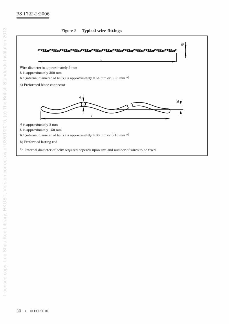
Figure 2 Typical wire fittings
Wire diameter is approximately 2 mm
L is approximately 380 mm
ID (internal diameter of helix) is approximately 2.54 mm or 3.25 mm A)
a) Preformed fence connector
d is approximately 2 mm
L is approximately 150 mm
ID (internal diameter of helix) is approximately 4.88 mm or 6.15 mm A)
b) Preformed lasting rod
A) Internal diameter of helix required depends upon size and number of wires to be fixed.
L
IDID
L
d
© BSI 2010
• 21
BS 1722-2:2006
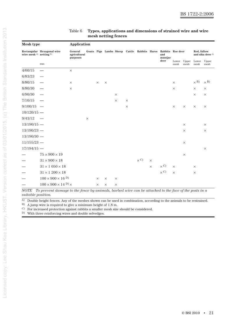
Table 6 Types, applications and dimensions of strained wire and wire mesh netting fences
Mesh type Application
Rectangularwire mesh A)
Hexagonal wire netting B)
mm
General agriculturalpurposes
Goats Pigs Lambs Sheep Cattle Rabbits Hares Rabbits and muntjac deer
Roe deer Red, fallowand sika deer A)
Lower mesh
Upper mesh
Lower mesh
Upper mesh
4/60/15 — ×
6/83/23 —
8/80/15 — × × × × × B) × B)
8/80/30 — × × × ×
6/90/30 — × × ×
7/10/15 — × ×
9/100/15 — × × × × ×
10/120/15 —
9/43/12 — ×
13/190/15 — × ×
13/190/23 — × ×
13/190/30 —
11/155/23 — ×
17/194/15 — ×
— 75 × 900 × 19 ×
— 31 × 900 × 18 × C) ×
— 31 × 1 050 × 18 × × C) × ×
— 31 × 1 200 × 18 × C) × ×
— 100 × 900 × 16 D) × × ×
— 100 × 900 × 14 D) × × × ×
NOTE To prevent damage to the fence by animals, barbed wire can be attached to the face of the posts in a suitable position.A) Double height fences. Any of the meshes shown can be used in combination, according to the animals to be restrained.B) A jump wire is required to give a minimum height of 1.8 m.C) For increased protection against rabbits a smaller mesh size should be considered.D) With three reinforcing wires and double selvedges.
© BSI 2010
BS 1722-2:2006
22 •
8.2.3 Fence posts and struts
Concrete fence posts and struts shall conform to the dimensionsspecified in Table 8. Straining posts and struts shall not be tapered.
Straining posts shall be provided with a firm bearing for struts, withinthe top third of the length above ground level (not including extensions for barbed wire). Straining posts shall be holed for attaching strainingfittings.
Intermediate posts shall be tapered to 75 mm × 75 mm at the top andshall be holed for the attachment of the top and bottom horizontal line wires and at least one intermediate horizontal wire.
Spacing of horizontal line wires shall be as specified in Table 1.
NOTE BS EN 10223-5 gives details of the number and spacing of horizontal wires in rectangular mesh fencing, which determines the position of fixing holes in posts.
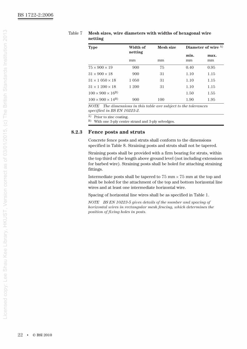
Table 7 Mesh sizes, wire diameters with widths of hexagonal wirenetting
Type Width ofnetting
mm
Mesh size
mm
Diameter of wire A)
min.mm
max.mm
75 × 900 × 19 900 75 0.40 0.95
31 × 900 × 18 900 31 1.10 1.15
31 × 1 050 × 18 1 050 31 1.10 1.15
31 × 1 200 × 18 1 200 31 1.10 1.15
100 × 900 × 16B) 1.50 1.55
100 × 900 × 14B) 900 100 1.90 1.95
NOTE The dimensions in this table are subject to the tolerances specified in BS EN 10223-2.A) Prior to zinc coating.B) With one 3-ply centre strand and 3-ply selvedges.
© BSI 2010

• 23
BS 1722-2:2006
Figure 3 General characteristics of wire mesh netting fences
a) Typical wire mesh fence showing wooden posts
b) Box section straining post assembly
Preformedlashing rodRectangular mesh
high tensile or mildsteel
Sprung steel or hightensile line wire
Wire connector
Straining postand strutassembly
Cross member
Retaining wire
Thrust plate
Intermediatepost (stake)
Netting ringsHexagonalmesh
Stay wire
© BSI 2010
BS 1722-2:2006
24 •
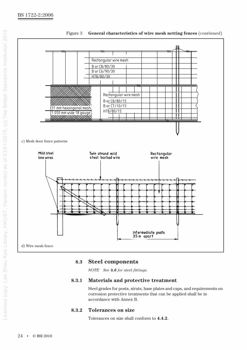
8.3 Steel componentsNOTE See 4.6 for steel fittings.
8.3.1 Materials and protective treatment
Steel grades for posts, struts, base plates and caps, and requirements on corrosion protective treatments that can be applied shall be in accordance with Annex B.
8.3.2 Tolerances on size
Tolerances on size shall conform to 4.4.2.
Figure 3 General characteristics of wire mesh netting fences (continued)
c) Mesh door fence patterns
d) Wire mesh fence
Rectangular wire mesh
B or C8/80/30B or C6/90/30HT8/80/30
Rectangular wire mesh
B or C8/80/15B or C7/10/15HT8/80/15
31 mm hexangonal mesh1 050 mm wide 18 gauge
© BSI 2010
• 25
BS 1722-2:2006
8.3.3 General construction
General construction shall conform to 4.4.3.
8.3.4 Fence posts and struts
Fence posts and struts shall conform to 4.4.4.
8.3.5 Base plates and dowels
Base plates and dowels shall conform to 4.4.5.
8.3.6 Welding
Welding shall conform to 4.4.6.
8.4 Timber componentsTimber components shall conform to Tables 4 and 5, as appropriate.
8.5 Fittings
8.5.1 Eye bolt strainers
Eye bolt strainers shall consist of 250 mm long bolts of at least 9.5 mm diameter and with an eye at one end. Eye bolt strainers for use with high tensile line wire shall have welded eyes. They shall be threaded and fitted with nuts and washers. Two-way eye bolt strainers shall be fitted with ring nuts.
Cleats, one to each eye bolt, shall be of uniform size and shall consist of mild steel angle not less than 38 mm × 38 mm × 5 mm. Eye bolt strainers and cleats shall be hot dip galvanized in accordance with BS EN ISO 1461.
8.5.2 Winding brackets
Winding brackets intended for attachment to a post shall be of mild steel, flat and at least 25 mm × 3 mm. They shall be fitted with a 12 mm minimum diameter winding bolt with a friction type, ferrule or ratchetwinder. Each winding bracket shall have one fixing of 10 mm diameter.
Winding brackets and fixing bolts shall be hot dip galvanized inaccordance with BS EN ISO 1461.
8.5.3 Stretcher bars
Stretcher bars shall consist of mild steel, flat, 30 mm × 6 mm, holed to allow attachment to the straining fittings by 8 mm diameter bolts. Stretcher bars shall be hot dip galvanized in accordance with BS EN ISO 1461 except that when used in conjunction with steel posts with a plastics covering they shall have the same protective treatment as the post.
8.5.4 Netting rings
Netting rings [see Figure 3a)] shall be formed from wire of at least 2 mmdiameter and shall be zinc coated in accordance with BS EN 10244-2.
© BSI 2010
BS 1722-2:2006
26 •
8.5.5 Hog rings
Hog rings shall be at least 4 mm × 1.5 mm and shall be zinc coated inaccordance with BS EN 10244-2:2001.
8.5.6 Staples
Staples shall conform to 4.6.5.
8.5.7 Bolts, nuts, washers and nails
Nails shall be plain round head nails conforming to BS 1202-1. Washers shall conform to BS 4320.
Bolts, nails and washers shall be hot dip galvanized in accordance with BS EN ISO 1461.
8.6 Concrete surrounding bases of posts and strutsConcrete for surrounding the bases of posts and struts shall conform to 4.7.
9 Installation of general pattern wire mesh fences
9.1 Line Line shall conform to 5.1.
9.2 Posts and strutsPosts and struts shall be installed in accordance with 5.2.
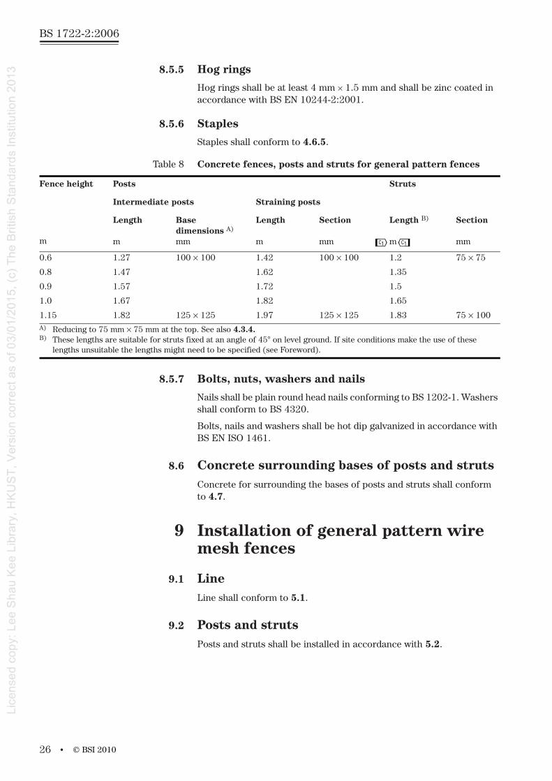
Table 8 Concrete fences, posts and struts for general pattern fences
Fence height
m
Posts Struts
Intermediate posts Straining posts
Length
m
Basedimensions A)
mm
Length
m
Section
mm
Length B)
m
Section
mm
0.6 1.27 100 × 100 1.42 100 × 100 1.2 75 × 75
0.8 1.47 1.62 1.35
0.9 1.57 1.72 1.5
1.0 1.67 1.82 1.65
1.15 1.82 125 × 125 1.97 125 × 125 1.83 75 × 100A) Reducing to 75 mm × 75 mm at the top. See also 4.3.4.B) These lengths are suitable for struts fixed at an angle of 45° on level ground. If site conditions make the use of these
lengths unsuitable the lengths might need to be specified (see Foreword).
© BSI 2010
P Q
• 27
BS 1722-2:2006
9.3 Strained wire and mesh
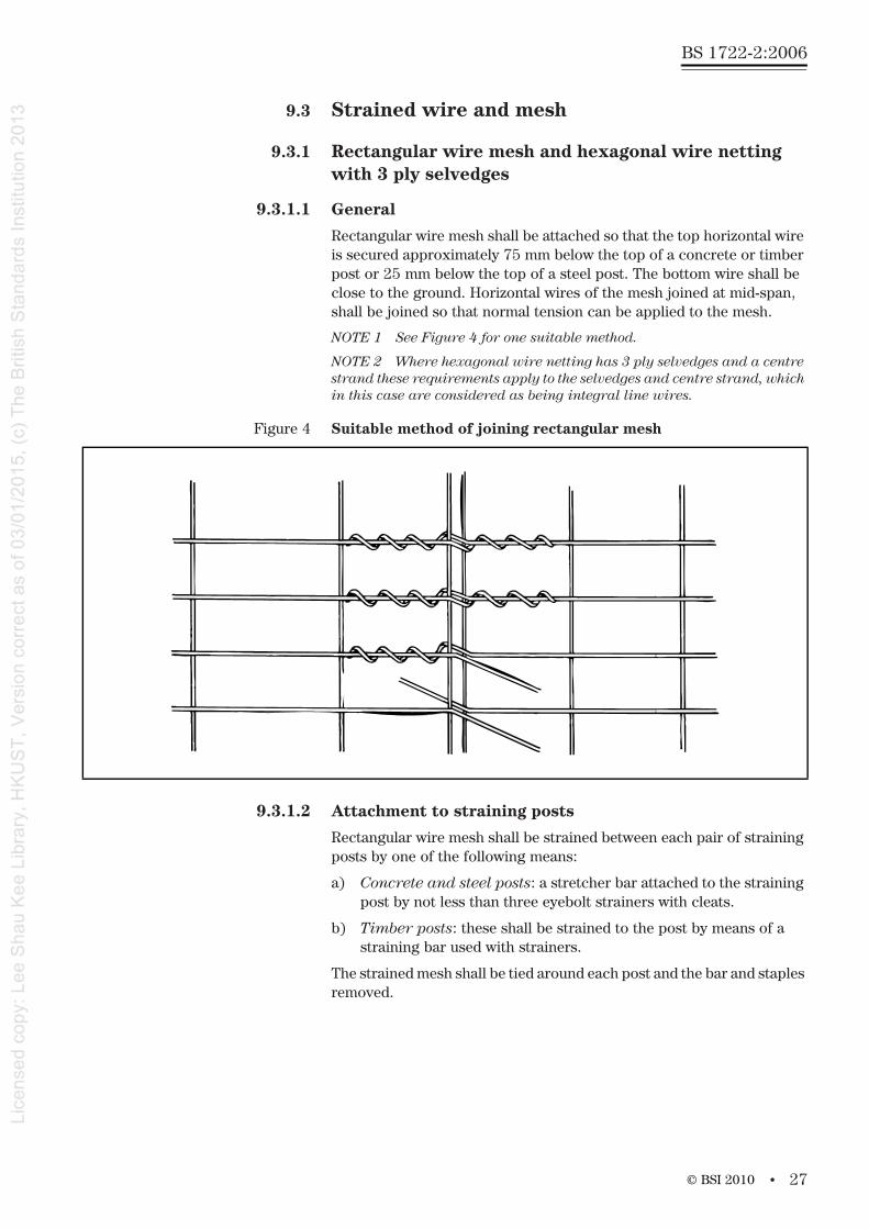
9.3.1 Rectangular wire mesh and hexagonal wire netting with 3 ply selvedges
9.3.1.1 General
Rectangular wire mesh shall be attached so that the top horizontal wire is secured approximately 75 mm below the top of a concrete or timber post or 25 mm below the top of a steel post. The bottom wire shall be close to the ground. Horizontal wires of the mesh joined at mid-span,shall be joined so that normal tension can be applied to the mesh.
NOTE 1 See Figure 4 for one suitable method.
NOTE 2 Where hexagonal wire netting has 3 ply selvedges and a centrestrand these requirements apply to the selvedges and centre strand, which in this case are considered as being integral line wires.
9.3.1.2 Attachment to straining posts
Rectangular wire mesh shall be strained between each pair of straining posts by one of the following means:
a) Concrete and steel posts: a stretcher bar attached to the straining post by not less than three eyebolt strainers with cleats.
b) Timber posts: these shall be strained to the post by means of a straining bar used with strainers.
The strained mesh shall be tied around each post and the bar and staples removed.
Figure 4 Suitable method of joining rectangular mesh
© BSI 2010
BS 1722-2:2006
28 •
9.3.1.3 Attachment to intermediate posts
The top and bottom horizontal wires of the rectangular wire mesh and at least one intermediate wire, as near the centre of the mesh as possible, shall be secured to each intermediate post by one of the following means:
a) Concrete and steel posts:
1) a wire stirrup passed through a hole in the post and secured to the horizontal wires by three complete turns on each side ofthe posts; or
2) a hair-pin staple passed through a hole in the post and the ends bent over twice or, if high tensile wire staples are used, once bent over.
b) Timber posts: a single zinc coated staple. Care shall be taken to avoid damaging the wire or its coating by driving the staple too farinto the post.
NOTE A running fit is generally sufficient on an intermediate post.
9.3.2 Hexagonal wire netting without 3-ply selvedges
9.3.2.1 General
Hexagonal wire netting, without 3-ply selvedges and a centre strand, shall be supported on two line wires. The top wire shall be secured approximately 75 mm below the top of concrete or timber postsor 25 mm below the top of steel posts. The bottom wire shall be close to the ground. Line wire joined at mid-span, shall be joined so that normal tension can be applied to the wire.
9.3.2.2 Attachment to straining posts
Each line wire shall be strained between each pair of straining posts by one of the following means.
a) Winding brackets or eye bolt strainers passed through a hole in the post and secured with a nut and washer. Eye bolt strainers fixed to intermediate straining posts shall, in addition, be fitted with ring nuts and in this case, the wire attached to the eye of the eye bolt strainer shall be tensioned before the ring nut is fixed.
b) Strained to the post using a selected straining tool and fixed with a staple driven into the post. Once strained, the free end of the line wire shall be passed around the post and secured to the main length.
NOTE Careful attention should be paid to the selection and use of the straining tool to restrict the damage caused to the wire.
© BSI 2010
• 29
BS 1722-2:2006
9.3.2.3 Attachment to intermediate posts
Each line wire shall be secured to each intermediate post by one of the following means.
a) For concrete posts:
1) a wire stirrup passed through a hole in the post and secured to the horizontal wires by three complete turns on each side of the post; or
2) a hair-pin staple passed through a hole in the post and the ends bent over twice or if high tensile wire staples are used, once bent over.
b) For steel posts:
1) as specified for concrete posts; or
2) the line wire passed through a hole in the post.
c) Timber posts: a single galvanized staple.
NOTE The staple should not be driven too far into the post in order to avoid damaging the wire or its coating. A running fit is generally sufficient for intermediate posts.
9.3.2.4 Netting
Hexagonal wire netting shall be stretched hand tight between posts and attached to the line wires by wire ties, netting rings (see 8.5.4) or hog rings (see 8.5.5) spaced approximately 450 mm apart. The netting shall be secured to each post at the top, middle and bottom by the means specified in 9.3.2.3.
NOTE The method used to attach hog rings should be such as to avoid damage being caused to the ring or its zinc coating, for instance as a result of being closed up too much.
The top edge of the netting for rabbit fencing shall be not less than 0.75 m above ground level. The bottom of a rabbit fence shall either be buried 150 mm and turned out towards the rabbit harbourage for 150 mm or, turned outwards on the surface for 150 mm towards the rabbit harbourage and held down with pegs at 1 m centres or coveredwith turves.
9.3.3 Barbed wire
If barbed wire is specified (see note to Table 6) it shall be attached tothe straining posts and intermediate posts by one of the means specified for line wires (see 5.3.1.2 and 5.3.1.3).
NOTE When tensioning high tensile barbed wire care should be taken toavoid any untwisting of the wire as a result of overstraining.
© BSI 2010
BS 1722-2:2006
30 •
10 Materials for spring steel and high tensile mesh fences
10.1 Wire
10.1.1 General
Wire shall conform to 8.1.1 to 8.1.5 and to 10.1.2 to 10.1.4.
NOTE See also 4.6 for some wire based fittings.
10.1.2 Barbed wire
Barbed wire shall conform to BS EN 10223-1.
10.1.3 Line wire
Line wire shall be zinc or zinc alloy coated spring steel wire conforming to BS EN 10244-2; it shall have a minimum nominal wire diameter of 2.65 mm, or for zinc coated high tensile wire it shall have a minimum nominal wire diameter of 2.5 mm.
10.1.4 High tensile rectangular wire mesh
Wire mesh shall be high tensile zinc coated and conform to Table 6 and BS EN 10223-5.
10.2 Timber componentsTimber components shall conform to their specified sizes within the tolerances given in 4.5.
10.3 Fittings
10.3.1 General
Fittings shall conform to 4.6 and 5.3.1.2 to 5.3.1.3.
10.3.2 Wire connectors
Wire connectors shall conform to 4.6.4.
10.3.3 Preformed lashing rods used to attach rectangular wire meshes to line wires
Preformed lashing rods shall consist of a single wire ofapproximately 2 mm cross-sectional dimension with a tensile strength of 1 250 N/mm2 formed into a helix approximately 150 mm long and with a central core in which a line wire and a horizontal wire of the mesh is retained.
NOTE Figure 2b) illustrates a typical example. The core diameter of the helix should take account of whether one or two widths of mesh are to be attached to the line wire.
10.4 Concrete surrounding bases of postsConcrete surrounding bases of posts shall conform to 4.7.
© BSI 2010
• 31
BS 1722-2:2006
11 Installation of spring steel and high tensile mesh fences
11.1 Line The top of the fence shall follow approximately the level of the ground along the line of the fence.
NOTE Unless specified (see Annex C) the installation of the fence does not include cutting or filling the ground to vary the levels.
The presence of any electricity, gas, water or other underground services shall be established prior to commencement of excavation, drilling or erection in the working area.
11.2 Posts and struts
11.2.1 General
Posts and struts shall conform to 5.2.1.
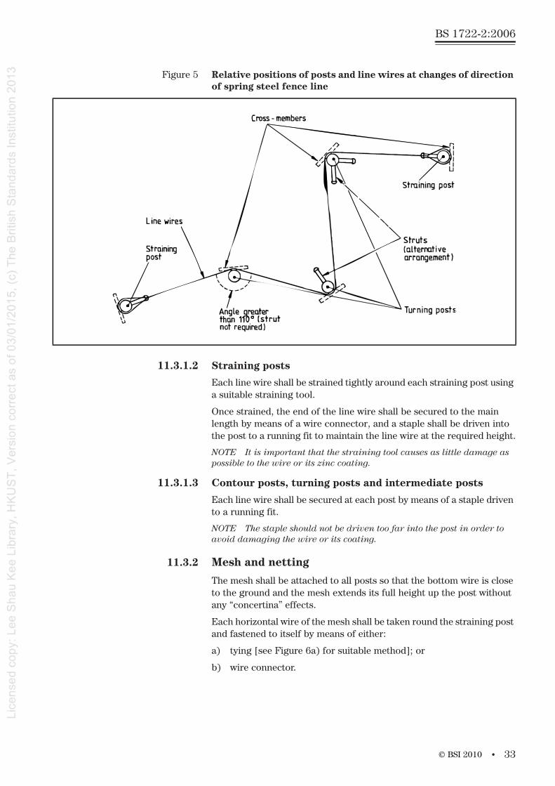
11.2.2 Straining posts, turning posts and contour posts (see Figure 5)
Straining posts shall be provided at all ends and at intervals of not morethan 1 000 m. Turning posts shall be provided at corners and lateral changes in direction. No more than three turning posts shall occur between any two straining posts. Contour posts shall be provided at acute ground undulations.
NOTE 1 An acute undulation is where either the fence crosses a gulley; or depression resulting in the bottom wire being some distance above the ground; or where it crosses a ridge so that the top or central wire would otherwise touch the ground.
When a post is used with a strut or struts (see 11.2.3) a cross member shall be fixed with two125 mm × 5 mm nails to the base of the post on the side opposite the strut or struts. Posts shall be set in the ground toa depth of at least 0.90 m with any cross member approximately at right angles to the resultant direction of strain (see Figure 4). The holes for posts set in concrete shall be not less than 0.45 m square in plan or if round, as might be produced by an auger, not less than 0.45 m in diameter.
NOTE 2 The shape of the hole should make allowance for any crossmember at the base of the post.
11.2.3 Struts
Struts shall be fitted to all straining posts in the direction of each line offencing and to all turning posts where the internal angle included by the line wire is less than 110°, i.e. the change in direction of the wire is greater than 70°.
NOTE In the case of turning posts, struts can either be fixed in the manner specified for straining posts or be arranged so that a single strutbisects the internal angle of the wire (see Figure 2). The choice of method is determined by the need for local access. In addition, struts projecting from the line of a fence can create a hazard to stock.
© BSI 2010
BS 1722-2:2006
32 •
The top of each strut shall be securely morticed into the straining post. At the bottom end of the strut a thrust plate shall be driven into the ground, nailed to the strut with 125 mm × 5 mm nails, and secured tothe base of the post by means of a retaining loop of spring steel wire[see Figure 3a)], fixed at one end with staples into the post andterminated at the other, either with a wire connector, or with staples into the post.
11.2.4 Intermediate posts (stakes)
Intermediate posts shall be provided between straining posts, turning posts and contour posts at intervals not exceeding 15 m on spring steel fences and 10 m on high tensile mesh fences.
Intermediate posts shall be set or driven into the ground to a depth of 0.6 m.
11.3 Strained wire and mesh
11.3.1 Line wires
11.3.1.1 General
At least three line wires shall be provided for deer fences, and at least two line wires shall be provided for all other fences. Where both rabbits and cattle are to be excluded an additional two line wires shall be provided at heights of approximately 0.3 m and 0.6 m from the ground [see Figure 3c)].
To introduce vertical tension into rectangular wire mesh the top and bottom wires shall be spaced approximately 100 mm further apart than the total width of the mesh so that the line wires are extended when the mesh is fixed [see Figure 3a)].
The bottom wire shall be fixed to the posts at ground level.
Line wire joined at mid-span, shall be joined so that normal tension can be applied to the wire.
NOTE 1 To increase the height of a mesh fence, additional lines of wire conforming to 10.1.2 or 10.1.3, generally known as “jump wires” can be added above the top of the mesh.
NOTE 2 As an aid to work and to avoid introducing kinks into the line wire it should be uncoiled from a wire dispenser.
© BSI 2010
• 33
BS 1722-2:2006
11.3.1.2 Straining posts
Each line wire shall be strained tightly around each straining post using a suitable straining tool.
Once strained, the end of the line wire shall be secured to the mainlength by means of a wire connector, and a staple shall be driven intothe post to a running fit to maintain the line wire at the required height.
NOTE It is important that the straining tool causes as little damage as possible to the wire or its zinc coating.
11.3.1.3 Contour posts, turning posts and intermediate posts
Each line wire shall be secured at each post by means of a staple drivento a running fit.
NOTE The staple should not be driven too far into the post in order to avoid damaging the wire or its coating.
11.3.2 Mesh and netting
The mesh shall be attached to all posts so that the bottom wire is close to the ground and the mesh extends its full height up the post without any “concertina” effects.
Each horizontal wire of the mesh shall be taken round the straining post and fastened to itself by means of either:
a) tying [see Figure 6a) for suitable method]; or
b) wire connector.
Figure 5 Relative positions of posts and line wires at changes of direction of spring steel fence line
© BSI 2010
BS 1722-2:2006
34 •
Rectangular wire mesh shall be tensioned using a straining tool in conjunction with round or flat straining bars and attached to line wire and fixed to each post by means of staples. The top and bottom wires shall be attached to the line wire with appropriately sized preformed lashing rods spaced at approximately 2 m centres and fixed to each postby means of staples. The mesh shall be strained to a straining post prior to stapling.
Horizontal wires of the mesh joined at mid-span, shall be joined so that normal tension can be applied to the mesh. (See Figure 6 for a suitable method.)
NOTE 1 Care should be taken to avoid mechanical damage to hightensile wires as this can result in breakage under tension.
Hexagonal wire netting shall be stretched hand tight between posts and attached to the line wires with netting rings, hog rings or wire ties, all spaced approximately 1 m apart. Where rectangular wire mesh is also installed (as in deer fences) preformed lashing rods spacedapproximately 2 m apart shall also be used. The netting shall be fixed toeach post by means of staples. For red, fallow and sika deer the fence shall be brought up to a minimum height of 1.8 m by providing a jump wire.
NOTE 2 The method used to attach hog rings should be such as to avoid damage being caused to the ring or its zinc coating, for instance as a result of being closed up too much.
The top edge of the netting for rabbit fencing shall be not lessthan 0.75 m above ground level. The bottom of a rabbit fence shall either be buried 150 mm and turned out towards the rabbit harbourage for 150 mm or, turned outwards on the surface for 150 mm towards the rabbit harbourage and held down with pegs at 1 m centres or covered with turves.
11.3.3 Barbed wire
If barbed wire is specified (see note to Table 1), it shall be attached to the straining posts and intermediate posts by the means specified for line wires.
NOTE When tensioning high tensile barbed wire, care should be taken to avoid any untwisting of the wire as a result of over-straining.
© BSI 2010

• 35
BS 1722-2:2006
12 Statement of conformity
12.1 Fence manufacturerOn delivery, the manufacturer/supplier of the fence shall provide the installer with a certificate, conforming to 12.3, confirming that the fence and/or gates are manufactured in accordance with the client’s instructions.
NOTE This certificate can be in the form of an invoice, provided this conforms to 12.3.
12.2 Fence installerOn completion, the fence installer shall provide the end user with a certificate, conforming to 12.3, confirming that the installation and materials used are in accordance with the client’s instructions.
NOTE This certificate can be in the form of an invoice provided this conforms to 12.3.
Figure 6 Suitable methods of tying horizontal wires
a) High tensile mesh tying
b) High tensile mesh wire connector
© BSI 2010
BS 1722-2:2006
36 •
12.3 CertificateIn addition to the requirements of 12.1 and 12.2, the certificate shall also include the following information:
a) the supplier’s name and address;
b) the contract or order number;
c) the date of delivery or installation, as appropriate:
d) the purchaser’s name and address.
12.4 StatementThe manufacturer and/or installer shall make a statement to the effect that it is their policy to conform to a previously client agreed and documented specification and to offer goods and/or services accordingly.
NOTE This could be done by inclusion in trade advertising and “terms of trading” statements supplied with quotations.
© BSI 2010
• 37
BS 1722-2:2006
Annex A (normative) Concrete components
A.1 Materials
A.1.1 CementCement for concrete shall be:
a) Portland cement (ordinary or rapid hardening) conforming toBS EN 197-1;
b) Portland blastfurnace cement conforming to BS EN 197-4; or
c) sulfate-resisting Portland cement conforming to BS 4027.
A.1.2 AggregateAggregate for concrete shall conform to the requirements of BS EN 12620.
Aggregate shall not exceed 10 mm nominal size.
A.1.3 AdmixturesAdmixtures for concrete shall conform as follows:
a) pigments: BS EN 12878;
b) pulverized-fuel ash: BS 3892;
c) concrete admixtures: BS EN 480 and BS EN 934 and used in accordance with BS EN 12839.
A.1.4 Chloride contentFor chloride content the requirements of BS EN 206-1:2000, 5.2.7 shall apply.
Calcium chloride and chloride based admixtures shall not be added toconcrete containing steel reinforcement.
A.1.5 ReinforcementReinforcement for concrete shall conform to BS 4449, BS 4482 or BS 4483.
A.2 MouldsMoulds shall remain rigid during placing and compaction of the concrete and shall prevent loss of water, grout or mortar. Moulds shall produce finished components accurately within the specified size limits.
Timber moulds shall be of closely jointed planed timber.
A.3 Manufacture
A.3.1 MixingConcrete shall be mixed in a mechanical mixer until uniform in colour and consistency.
© BSI 2010
BS 1722-2:2006
38 •
A.3.2 Placing and compactionConcrete shall be placed as soon as practicable after mixing, and shall be thoroughly compacted by vibration, tamping or other method so thaton demoulding the surface is free from honeycombing and other large blemishes (see A.4).
NOTE Blemishes do not include small surface voids caused by entrapped air or water.
A.3.3 Location of reinforcementReinforcement shall be prefabricated and located during placing and compacting of the concrete, so that the cover of concrete measured from main external faces and from the top of a post or strut, is atleast 15 mm, or 10 mm if the section is 100 × 100 mm or less.
The length of the assembled reinforcement shall be at least equal to the minimum length of the component, minus up to 100 mm to allow for the minimum cover and up to 75 mm to allow for cutting, prefabrication and location.
Reinforcement shall extend beyond the centre line of the uppermost line wire hole or beyond the top edge of the uppermost rail fixing point, asappropriate.
NOTE If the ends of components are splayed, each bar can be of equal length.
A.3.4 Protection from freezingMaterials that have been exposed to below freezing point shall not beused unless completely thawed.
Components shall not be moulded if the mould is below freezing point. The temperature of fresh concrete shall be not less than 5°C at the time of placing.
A.3.5 MaturingComponents shall not be used unless:
a) the concrete has a strength of 45 N/mm2, as tested in accordance with A.5; or
b) they have been allowed to mature under suitable conditions for at least 28 days at normal ambient temperatures.
A.4 Surface characteristics
A.4.1 Surface finish as castThe surface finish shall be assessed against the reference photographs in Annex B of BS EN 12839:2001. Furthermore, the total area of blowholes shall not exceed 3% of the concrete surface and no blowhole shall exceed 150 mm2.
NOTE It is acknowledged that semi-dry cast posts might have a more visually open surface texture than shown in these photographs.
A.4.2 Surface finish as treatedThe requirements of BS EN 12839:2001, 5.3.2 shall apply.
© BSI 2010
• 39
BS 1722-2:2006
A.5 TestsTo demonstrate compliance, testing shall comprise of initial type testing and factory production control in accordance with BS EN 12839:2001, Clause 6.
A.6 Product informationThe manufacturer shall give the following information on at least one product by unit of packaging, delivery notes, certificate or anydocumentation supplied with components in accordance with BS EN 12839:2001, ZA.3:
1) Name (or identifying mark) and address of manufacturer.
2) Last 2 digits of the year in which the marking was affixed.
3) BS 1722 and BS EN 12839: Elements for Fences.
4) Load bearing capacity, expressed in newton’s according to the result of initial type testing, rounded down to the nearest 10.
Annex B (normative) Steel components and protective treatment
B.1 Material formSteel posts and struts shall be produced from the following:
a) rolled steel angle (RSA) or angle re-rolled from railway lines3);
b) rectangular hollow sections (RHS);
c) circular hollow section (CHS) or round tubes;
B.2 Material gradesThe steel grade(s) employed shall be specified by the customer (the purchaser, fence designer, supplier, component manufacturer, fabricator or erector, as applicable), on the basis of the mechanical properties, formability and weldability required. Appropriate mild steel grades shall be selected from Table B.1.
As a general guideline, steel grades shall have a minimum yield strength in excess of 175 N/mm², unless the design permits lower strength materials to be employed.
NOTE 1 Tubes and hollow sections can be hot or cold formed.
Where components are to be hot dipped galvanized, the purchaser shall confirm with the supplier that the steel composition is suitable.
NOTE 3 A non-exhaustive range of recommended material grades isgiven in Table B.1.
3) Re-rolled angles are normally produced from steel sections.
© BSI 2010
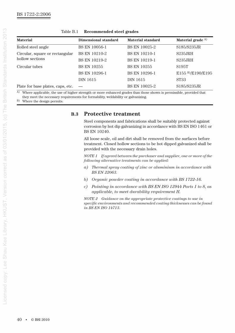
BS 1722-2:2006
40 •
B.3 Protective treatmentSteel components and fabrications shall be suitably protected againstcorrosion by hot dip galvanizing in accordance with BS EN ISO 1461 or BS EN 10240.
All loose scale, oil and dirt shall be removed from the surfaces before treatment. Closed hollow sections to be hot dipped galvanized shall be provided with the necessary drain holes.
NOTE 1 If agreed between the purchaser and supplier, one or more of the following alternative treatments can be applied:
a) Thermal spray coating of zinc or aluminium in accordance withBS EN 22063.
b) Organic powder coating in accordance with BS 1722-16.
c) Painting in accordance with BS EN ISO 12944 Parts 1 to 8, as applicable, to meet durability requirement H.
NOTE 2 Guidance on the appropriate protective coatings to use in specific environments and recommended coating thicknesses can be found in BS EN ISO 14713.
Table B.1 Recommended steel grades
Material Dimensional standard Material standard Material grade A)
Rolled steel angle BS EN 10056-1 BS EN 10025-2 S185/S235JR
Circular, square or rectangular hollow sections
BS EN 10210-2 BS EN 10210-1 S235JRH
BS EN 10219-2 BS EN 10219-1 S235JRH
Circular tubes BS EN 10255 BS EN 10255 S195T
BS EN 10296-1 BS EN 10296-1 E155 B)/E190/E195
DIN 1615 DIN 1615 ST33
Plate for base plates, caps, etc. — BS EN 10025-2 S185/S235JRA) Where applicable, the use of higher strength or more enhanced grades than those shown is permissible, provided that
they meet the necessary requirements for formability, weldability or galvanizing.B) Where the design permits.
© BSI 2010
• 41
BS 1722-2:2006
Annex C (informative) Specifying a strained wire fence
C.1 GeneralWhen preparing a specification for a fence it is important that precise details of the requirements of the fence and the installation site are provided. This annex lists items that should be specified at the time of ordering the fence. As conditions vary from site to site, this annex should not be assumed to be exhaustive.
C.2 Site conditionsThe following items should at least be agreed between the supplier and purchaser at the time of enquiry and/or order:
a) the line and length of fence (see 5.1);
b) the profile of the fence and ground clearance;
c) the site preparation (see 5.1);
1) clearance;
2) cutting or filling of ground level.
d) any specific requirements for non-standard post lengths due toground conditions (see Foreword);
NOTE The requirements for lengths of posts and struts in this standard (see Tables 3, 4, 5 and 8) and foundation sizes are for “normal” ground conditions. This standard does not cover conditionsof particularly firm or soft ground, where other lengths or foundationsizes might be required. Base details of steel and timber posts and the method of setting these are also affected by ground conditions.
e) number, position and specification of any gates and type required.
C.3 Construction of strained wire fenceThe following items should at least be agreed between the supplier and purchaser at the time of enquiry and/or order:
a) fence type reference (related to proposed use of fence) (see Table 1);
b) type of strained wire, including special features and additionallines of barbed wire;
c) type of line wire:
1) low carbon steel (mild steel) (general pattern fences only);
2) high tensile steel;
3) spring steel;
4) plastics coated high tensile steel;
5) plastics coated spring steel (dropper pattern fences only).
d) type of barbed wire:
1) low carbon steel (mild steel);
2) high tensile steel.
© BSI 2010
BS 1722-2:2006
42 •
e) posts and struts:
1) material of posts and struts (see Table 1):
i) concrete, including;
standard of surface finish, assessed against the reference photographs in BS EN 12839:2001, Annex B and;
If it is desired that sharp edges are removed from all longarrises of concrete posts, this should be agreed as an additional requirement of the specification (see 4.3.4).
ii) steel;
iii) timber.
2) steel:
i) type of section (see Table 3);
ii) type of protective treatment.
3) timber:
i) any limits on species to use;
ii) hardwood;
iii) softwood;
iv) round, cleft or sawn;
v) preservative treatment.
4) length;
NOTE 1 Lengths and base details is affected by groundconditions.
5) base details of steel or timber posts, including, if concrete or rammed earth;
6) any specific requirements for spacing of posts.
NOTE 2 The maximum centres for posts are specified in 5.3. If shorter bays are required they should be specified. The distance between intermediate posts in dropper pattern fences should be specified.
f) fittings, including particular requirements for the attachment of line wires or barbed wire;
g) droppers:
1) type of dropper;
2) number of droppers to be used in each bay between posts.
© BSI 2010
• 43
BS 1722-2:2006
C.4 Construction of rectangular wire mesh and hexagonal wire netting fenceThe following items should at least be agreed between the supplier and purchaser at the time of enquiry and/or order:
a) type of fence (fence type reference):
1) general pattern;
2) spring steel pattern;
3) high strength mesh.
b) mesh width and pattern (related to proposed use of fence);
c) type of mesh:
1) rectangular wire mesh;
2) hexagonal wire netting (if for rabbits specify if turned out or buried);
3) both rectangular wire mesh and hexagonal wire netting.
d) posts and struts:
1) materials of posts and struts:
i) concrete, including;
standard of surface finish, assessed against the reference photographs in BS EN 12839:2001, Annex B and;
If it is desired that sharp edges are removed from all long arrises of concrete posts, this should be agreed as an additional requirement of the specification (see 8.2.2).
ii) steel;
iii) timber.
2) steel:
i) type of section;
ii) type of protective treatment.
3) timber:
i) any limits on species to use;
ii) hardwood;
iii) softwood;
iv) round sawn or cleft;
v) preservative treatment.
4) base details for steel or timber posts and the method of setting (i.e. in concrete or rammed backfill, or driven);
5) any specific requirements for spacing of posts;
e) fittings [particular requirements for the attachment of mesh wires (including line wires)].
© BSI 2010
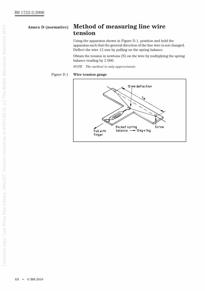
BS 1722-2:2006
44 •
Annex D (normative) Method of measuring line wire tensionUsing the apparatus shown in Figure D.1, position and hold the apparatus such that the general direction of the line wire is not changed. Deflect the wire 12 mm by pulling on the spring balance.
Obtain the tension in newtons (N) on the wire by multiplying the spring balance reading by 2 000.
NOTE The method is only approximate.
Figure D.1 Wire tension gauge
© BSI 2010
• 45
BS 1722-2:2006
Annex E (informative) Determination of moisture contentMoisture content should not exceed 28% when measured with a calibrated moisture meter of the electrical resistance type, fitted with insulated probes that can be hammered into wood to the depth specified in Table E.1.
When determining the suitability of a charge of timber for preservation, moisture readings should be made on no fewer than (n/2) separatecomponents, where n is the total number of components in the charge. The components to be measured should be taken from random positions in the charge. The number of heartwood and sapwood facessampled should reflect the relative proportions of these types of woodin the charge as a whole.
If preferred, the oven-dry method of determining moisture content as described in BS EN 212 may be used in place of a moisture meter.
To achieve the recommended moisture content of 28% (m/m) timbercan be either air dried or kiln dried. For either process it is essential that fencing timber is debarked and stacked so that air can circulate freely. In winter little natural drying is likely, therefore kiln drying may be the only effective solution.
Table E.1 Determination of moisture content of timber to be treated for use in fencing
Type of timber Length of electrodes within thetimber
Maximum indicated moisturecontent in an sample%
a) All sapwood 25 mm, or sapwood thickness if less 28
b) Heartwood of wood species other than those listed in c):
posts
other components
25 mm
12 mm
c) Heartwood of sweet chestnut, dahoma, danta, guarea, kapur, kempas and oak.
5 mm
© BSI 2010
BS 1722-2:2006
46 •
BibliographyFor dated references, only the edition cited applies. For undated references, the latest edition of the referenced document (including any amendments) applies.
BS 1722, Fences
BS EN 212, Wood preservatives – General guidance on sampling and preparation for analysis of wood preservatives and treated timber
© BSI 2010

This page deliberately left blank
BS 1722-2:2006

BSI – British Standards InstitutionBSI is the independent national body responsible for preparing British Standards. It presents the UK view on standards in Europe and at the international level. It is incorporated by Royal Charter.
RevisionsBritish Standards are updated by amendment or revision. Users of British Standards should make sure that they possess the latest amendments or editions.
It is the constant aim of BSI to improve the quality of our products and services. We would be grateful if anyone finding an inaccuracy or ambiguity while using this British Standard would inform the Secretary of the technical committee responsible, the identity of which can be found on the inside front cover. Tel: +44 (0)20 8996 9000. Fax: +44 (0)20 8996 7400.
BSI offers members an individual updating service called PLUS which ensures that subscribers automatically receive the latest editions of standards.
Buying standardsOrders for all BSI, international and foreign standards publications should be addressed to Customer Services. Tel: +44 (0)20 8996 9001. Fax: +44 (0)20 8996 7001. Email: [email protected]. Standards are also available from the BSI website at http://www.bsi-global.com.
In response to orders for international standards, it is BSI policy to supply the BSI implementation of those that have been published as British Standards, unless otherwise requested.
Information on standardsBSI provides a wide range of information on national, European and international standards through its Library and its Technical Help to Exporters Service. Various BSI electronic information services are also available which give details on all its products and services. Contact the Information Centre. Tel: +44 (0)20 8996 7111. Fax: +44 (0)20 8996 7048. Email: [email protected].
Subscribing members of BSI are kept up to date with standards developments and receive substantial discounts on the purchase price of standards. For details of these and other benefits contact Membership Administration. Tel: +44 (0)20 8996 7002.Fax: +44 (0)20 8996 7001. Email: [email protected].
Information regarding online access to British Standards via British Standards Online can be found at http://www.bsi-global.com/bsonline.
Further information about BSI is available on the BSI website at http://www.bsi-global.com.
CopyrightCopyright subsists in all BSI publications. BSI also holds the copyright, in the UK, of the publications of the international standardization bodies. Except as permitted under the Copyright, Designs and Patents Act 1988 no extract may be reproduced, stored in a retrieval system or transmitted in any form or by any means – electronic, photocopying, recording or otherwise – without prior written permission from BSI.
This does not preclude the free use, in the course of implementing the standard, ofnecessary details such as symbols, and size, type or grade designations. If these details are to be used for any other purpose than implementation then the prior written permission of BSI must be obtained.
Details and advice can be obtained from the Copyright & Licensing Manager.Tel: +44 (0)20 8996 7070. Fax: +44 (0)20 8996 7553.Email: [email protected].
BS 1722-2:2006
389 Chiswick High RoadLondonW4 4AL