femtocell deployment to minimize performance degradation in mobile wimax systems
TRANSCRIPT

8/2/2019 Femtocell Deployment to Minimize Performance Degradation in Mobile WiMAX Systems
http://slidepdf.com/reader/full/femtocell-deployment-to-minimize-performance-degradation-in-mobile-wimax-systems 1/11
Femtocell Deployment to Minimize Performance
Degradation in Mobile WiMAX Systems
Chang Seup Kim, Bum-Gon Choi, Ju Yong Lee, Tae-Jin Lee,Hyunseung Choo, and Min Young Chung
School of Information and Communication EngineeringSungkyunkwan University
300, Chunchun-dong, Jangan-gu, Suwon, Kyunggi-do, 440-746, Korea
Abstract. Femtocell is one of the promising technologies for improving
service quality and data rate of indoor users. Femtocell is short-range, low-cost, and low-power base stations (BS) installed by the consumer indoors.Even though femtocell can provide improved home coverage and capacityfor indoor users, it causes interference to macrocell users when femtocelluses the same frequency band of macrocell. To reduce the interference be-tween macrocell and femtocell, it is needed to analyze the characteristic of macrocell and femtocell considering various interference scenarios. In thispaper, we investigate the uplink and downlink capacity of macrocell andfemtocell according to the strength of femtocell transmit power and thenumber of femtocells through simulations. Simulation results show that
femtocell transmit power and the number of femtocells affect the perfor-mance of macrocell. From the results, we find the adequate femtocell trans-mit power which minimize the performance degradation of macrocell andfemtocell. We also investigate capacities of macrocell and femtocell accord-ing to the locations of femtocell BS and macrocell UE.
Keywords: Femtocell, Macrocell, Co-Channel Interference, Powercontrol.
1 Introduction
Mobile WiMAX (IEEE 802.16e) based on IEEE 802.16e standard has been com-mercialized in 2006 with rapid growth of various multimedia applications [1,2].Recently, user demands for various multimedia services such as mobile IPTVare continuously increasing. On the other hand, it is expected that 60 percentof voice calls and 90 percent of data services will take place in indoors [3], andin current mobile communication systems, the signal strength transmitted frombase station (BS) can be very low in indoor environments because the signal
This work was supported by National Research Foundation of Korea Grant funded bythe Korean Government (2009-0074466) and by the MKE (The Ministry of Knowl-edge Economy), Korea, under the ITRC (Information Technology Research Center)support program supervised by the NIPA (National IT Industry Promotion Agency)(NIPA-2009-(C1090-0902-0005) and NIPA-2009-(C1090-0902-0046)).
Corresponding author.
D. Taniar et al. (Eds.): ICCSA 2010, Part III, LNCS 6018, pp. 85–95, 2010.c Springer-Verlag Berlin Heidelberg 2010
8/2/2019 Femtocell Deployment to Minimize Performance Degradation in Mobile WiMAX Systems
http://slidepdf.com/reader/full/femtocell-deployment-to-minimize-performance-degradation-in-mobile-wimax-systems 2/11
86 C.S. Kim et al.
strength may be severely attenuated when it penetrates the obstacles such aswalls. Thus, providing high data rate services to indoor users is difficult only inmobile WiMAX systems. Therefore, the mobile WiMAX has performed femtocellstandardization in two phases . The first phase of a WiMAX femtocell system,
which requires no air interface or UE change, is expected to be available in thenear future. More advanced and optimized femtocell features in phase 2 will beavailable upon completion of IEEE 802.16m and as part of WiMAX Release 2.0with target deployments [4].
Femtocell is connected to IP based backhaul such as digital subscriber line(DSL) or cable modem, which provides lower cost than wireless mobile commu-nication systems. Femtocells can achieve a high signal-to-interference-plus-noiseratio (SINR) with low transmit power because the distance between transmitterand receiver is short. In addition, the operators can save costs when femtocell
accommodates traffic concentrated to macrocell of current mobile communica-tion. On the other hand, users can receive improved data speeds and servicequality with inexpensive costs. Although femtocell has many advantages in in-door environments, some technical issues, such as spectrum assignment of fem-tocell, access policy, network synchronization, handover, self-optimization, andself-configuration, should be solved to be effectively deployed in existing mobileWiMAX systems [5]. Especially, spectrum assignment for avoiding interferencebetween macrocell and femtocell is an important issue since interference maycauses severe degradation of throughput and service quality [6,7,8].
In mobile WiMAX system, throughput is determined by radius of macrocell,distribution of femtocell, and density of femtocell [9]. The interference charac-teristics under co-channel environments are presented in [10]. If femtocells aredeployed in mobile WiMAX systems, interference from femtocells can affect theperformance of mobile WiMAX systems. In this paper, we evaluate uplink anddownlink capacity of macrocell and femtocell by simulation under various inter-ference scenarios. We investigate the adequate femtocell transmit power level,which minimizes the performance degradation of mobile WiMAX system andcan achieve enough femtocell throughput. Also, we examine the effect of the
locations of femtocell BS and macrocell UE.The rest of this paper is organized as follows. Section 2 provides interference
scenarios in the environment where femtocells and macrocells coexist. Section 3describes the system model and propagation models. In Section 4, we examinethe uplink and downlink capacity of the macrocell and femtocell according tothe strength of femtocell transmit power, number of femtocells, and locations of femtocell BS and macrocell UE. Finally, we conclude in Section 5.
2 Interference Scenarios of Femtocells in Mobile WiMAX
Systems
When femtocells operate in the same spectrum in mobile WiMAX systems, thecharacteristic of interference depends on the method for channel assignment[11][12]. Channel assignment method for macrocell and femtocell is classified

8/2/2019 Femtocell Deployment to Minimize Performance Degradation in Mobile WiMAX Systems
http://slidepdf.com/reader/full/femtocell-deployment-to-minimize-performance-degradation-in-mobile-wimax-systems 3/11
Femtocell Deployment to Minimize Performance Degradation 87
into orthogonal and common channel assignment. Orthogonal channel assign-ment does not cause co-channel interference between the macrocell and fem-tocell because the femtocells use different channels with macrocell. However,orthogonal channel assignment has a low spectrum efficiency because frequency
resources for the macrocell and femtocell are different. On the other hand, com-mon channel assignment has a high spectrum efficiency because macrocell andfemtocell can use all of the spectrum. However, there exists a problem of co-channel interference in common channel assignment method.
In common channel assignment, co-channel interference between macrocelland femtocell should be reduced to guarantee service quality of users. We an-alyze the co-channel interference between macrocell and femtocell according tolink direction and the locations of femtocell BS and macrocell UE. Co-channelinterference scenario between macrocell and femtocell is shown in Fig. 1. In case
of uplink, interferences of macrocell and femtocell are caused by femtocell UEand macrocell UE, respectively. Similarly, in downlink, interferences of macrocelland femtocell are caused by femtocell BS and macrocell BS. If macro/femtocellUE is close to femto/macrocell BS, interference between macrocell and femtocellbecomes large. Thus, the channel capacity of macro/femtocell may be signifi-cantly deteriorated.
Fig. 1. Co-channel interference scenario between macrocell and femtocell
Fig. 2. Co-channel interference scenario between femtocells
8/2/2019 Femtocell Deployment to Minimize Performance Degradation in Mobile WiMAX Systems
http://slidepdf.com/reader/full/femtocell-deployment-to-minimize-performance-degradation-in-mobile-wimax-systems 4/11
88 C.S. Kim et al.
When femtocells are deployed in a macrocell, we should also consider co-channel interference among femtocells as shown in Fig. 2. Interferences are causedby neighboring femtocell BS and femtocell UE. Especially, when the distancebetween femtocells is short, the impact of interference from neighboring femtocell
may be high. That is, co-channel interference between femtocells can be a seriousproblem when a lot of femtocells are concentrated in a small area.
3 System Model
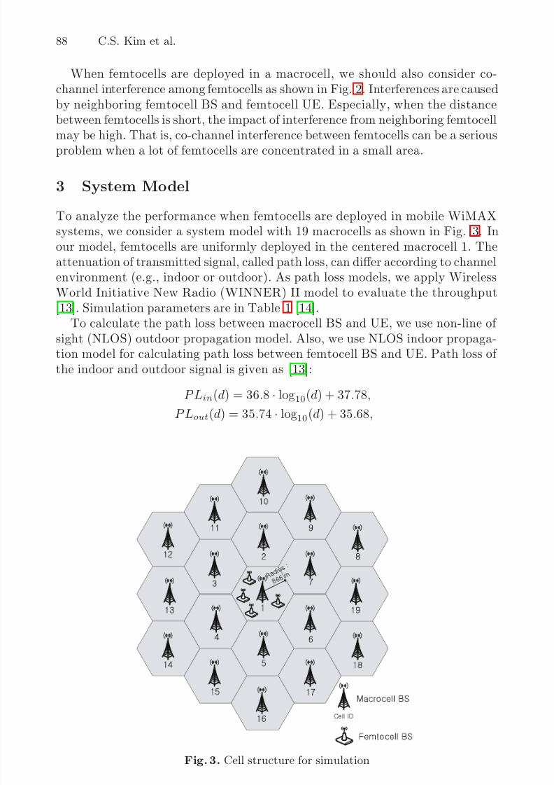
To analyze the performance when femtocells are deployed in mobile WiMAXsystems, we consider a system model with 19 macrocells as shown in Fig. 3. Inour model, femtocells are uniformly deployed in the centered macrocell 1. Theattenuation of transmitted signal, called path loss, can differ according to channel
environment (e.g., indoor or outdoor). As path loss models, we apply WirelessWorld Initiative New Radio (WINNER) II model to evaluate the throughput[13]. Simulation parameters are in Table 1 [14].
To calculate the path loss between macrocell BS and UE, we use non-line of sight (NLOS) outdoor propagation model. Also, we use NLOS indoor propaga-tion model for calculating path loss between femtocell BS and UE. Path loss of the indoor and outdoor signal is given as [13]:
PLin(d) = 36.8 · log10(d) + 37.78,
PLout(d) = 35.74·
log10(d) + 35.68,
Fig. 3. Cell structure for simulation
8/2/2019 Femtocell Deployment to Minimize Performance Degradation in Mobile WiMAX Systems
http://slidepdf.com/reader/full/femtocell-deployment-to-minimize-performance-degradation-in-mobile-wimax-systems 5/11
Femtocell Deployment to Minimize Performance Degradation 89
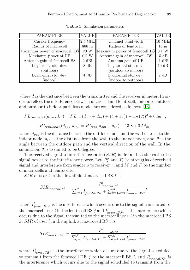
Table 1. Simulation parameters
PARAMETER VALUE PARAMETER VALUE
Carrier frequency 2.5 GHz Channel bandwidth 10 MHz
Radius of macrocell 866 m Radius of femtocell 10 mMaximum power of macrocell BS 20 W Maximum power of femtocell BS 0.1 W
Maximum power of UE 0.2 W Antenna gain of macrocell BS 15 dBiAntenna gain of femtocell BS 2 dBi Antenna gain of UE -1 dBi
Lognormal std. dev. 8 dB Lognormal std. dev. 10 dB(outdoor) (outdoor to indoor)
Lognormal std. dev. 4 dB Lognormal std. dev. 7 dB(indoor) (indoor to outdoor)
where d is the distance between the transmitter and the receiver in meter. In or-der to reflect the interference between macrocell and femtocell, indoor to outdoorand outdoor to indoor path loss model are considered as follows [13].
PLin to out(dout, din) = PLout(dout + din) + 14 + 15(1− cos(θ))2 + 0.5din,
PLout to in(dout, din) = PLout(dout + din) + 13.8 + 0.5din,
where dout is the distance between the outdoor node and the wall nearest to theindoor node, din is the distance from the wall to the indoor node, and θ is theangle between the outdoor path and the vertical direction of the wall. In thesimulation, θ is assumed to be 0 degree.
The received signal to interference ratio (SIR) is defined as the ratio of asignal power to the interference power. Let P rs and I rs be strengths of receivedsignal and interference from sender s to receiver r, and M and F be the numberof macrocells and femtocells.
SIR of user l in the downlink at macrocell BS i is:
SIR
l
macroBSi =
P lmacroBSi
F j=1 I
lfemtoBSj +
M k=1,k=i I
lmacroBSk ,
where I lfemtoBSj is the interference which occurs due to the signal transmited to
the macrocell user l in the femtocell BS j and I lmacroBSk is the interference which
occurs due to the signal transmited to the macrocell user l in the macrocell BSk. SIR of user l in the uplink at macrocell BS i is:
SIRi
macroUEl =
P imacroUEl
F j=1 I ifemtoUEj +
M k=1,k=l I imacroUEk
,
where I ifemtoUEj is the interference which occurs due to the signal scheduled
to transmit from the femtocell UE j to the macrocell BS i, and I imacroUEk is
the interference which occurs due to the signal scheduled to transmit from the

8/2/2019 Femtocell Deployment to Minimize Performance Degradation in Mobile WiMAX Systems
http://slidepdf.com/reader/full/femtocell-deployment-to-minimize-performance-degradation-in-mobile-wimax-systems 6/11
90 C.S. Kim et al.
macrocell UE k to the macrocell BS i. SIR of user l in the downlink at femtocellBS i is:
SIRlfemtoBSi =
P lfemtoBSi
F
j=1,j=i I lfemtoBSj +
M
k=1 I lmacroBSk
,
SIR of user l in the uplink at femtocell BS i is:
SIRifemtoUEl =
P ifemtoUEl
F
j=1,j=l I ifemtoUEj +
M
k=1 I imacroUEk
.
The received SIR is used to calculate channel capacity with the Shannon-Hartley
theorem. Channel capacityC
is calculated as follows.C = BW · log2(1 + SIR),
where BW is channel bandwidth in Hz.
4 Performance Evaluation
Fig. 4 shows uplink and downlink channel capacity of macrocell according to
the number of femtocells. As the number of femtocell increases, the uplink chan-nel capacity of macrocell steeply decreases, but downlink channel capacity of macrocell decreases more slowly than uplink channel capacity. The reason isthat uplink transmit power of macrocell UE is lower than downlink transmitpower of macrocell BS and strength of uplink interference is similar to strengthof downlink interference. In order to maintain uplink and downlink channel ca-pacity of macrocell high, the maximum transmit power of femtocell BS and UEis controlled. We set the transmitted power of femtocell BS and UE to 0.1 W,0.01 W, and 0.001 W in the simulation. When the transmitted power of femtocell
UE uses 0.001 W, the decreasing slope of uplink channel capacity of macrocell isreduced because co-channel interference from femtocell UE is decreased. On theother hand, macrocell UE in the downlink can get higher SIR than uplink of macrocell due to a high signal strength of macrocell BS. However, the downlinkchannel capacity of macrocell has smaller improvement than uplink of macrocelleven if the transmitted power of femtocell BS uses 0.001 W.
Compared with the channel capacity of macrocell as shown in Fig. 4, uplinkand downlink channel capacity of femtocell is high as shown in Fig. 5. Femtocellhas a high received SIR because the distance between femtocell BS and UE
is shorter than the distance between macrocell BS and UE. Since transmittedpower of macrocell UE is low compared with macrocell BS, co-channel inter-ference from macrocell UE is relatively low. Although the transmitted powerof femtocell’s UE is weakened, the uplink channel capacity of femtocell main-tains high. Accordingly, we can increase the uplink channel capacity of macro-cell. The downlink channel capacity of femtocell is constant because interference

8/2/2019 Femtocell Deployment to Minimize Performance Degradation in Mobile WiMAX Systems
http://slidepdf.com/reader/full/femtocell-deployment-to-minimize-performance-degradation-in-mobile-wimax-systems 7/11
Femtocell Deployment to Minimize Performance Degradation 91
Fig. 4. Uplink and downlink channel capacity of macrocell
Fig. 5. Uplink and downlink channel capacity of femtocell
from macrocell BS is more dominant than interference of neighboring femto-
cells. When the transmitted power of femtocell BS uses 0.001 W, the downlinkchannel capacity of femtocell is about 90 Mbps. In this setting, femtocell canprovide subscriber with enough service quality and data speed while minimizingthe performance degradation of macrocell.
We consider the environment where transmitted power of femtocell BS andUE is fixed to 0.001 W. Fig. 6 shows downlink and uplink channel capacity

8/2/2019 Femtocell Deployment to Minimize Performance Degradation in Mobile WiMAX Systems
http://slidepdf.com/reader/full/femtocell-deployment-to-minimize-performance-degradation-in-mobile-wimax-systems 8/11
92 C.S. Kim et al.
(a) Downlink
(b) Uplink
Fig. 6. Channel capacity of macrocell UE according to locations (The transmittedpower of femtocell BS and UE is 0.001 W)
8/2/2019 Femtocell Deployment to Minimize Performance Degradation in Mobile WiMAX Systems
http://slidepdf.com/reader/full/femtocell-deployment-to-minimize-performance-degradation-in-mobile-wimax-systems 9/11
Femtocell Deployment to Minimize Performance Degradation 93
(a) Downlink
(b) Uplink
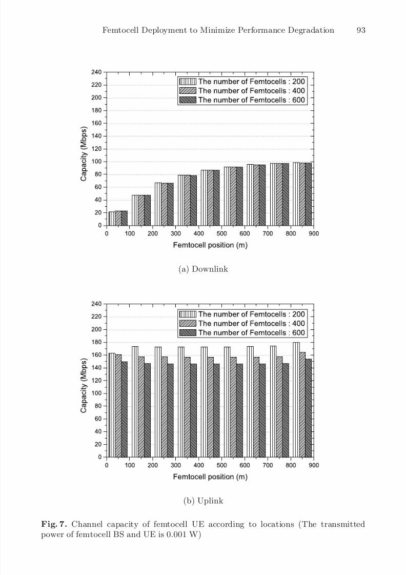
Fig. 7. Channel capacity of femtocell UE according to locations (The transmittedpower of femtocell BS and UE is 0.001 W)

8/2/2019 Femtocell Deployment to Minimize Performance Degradation in Mobile WiMAX Systems
http://slidepdf.com/reader/full/femtocell-deployment-to-minimize-performance-degradation-in-mobile-wimax-systems 10/11
94 C.S. Kim et al.
of macrocell according to the locations of macrocell UE. Macrocell UE has ahigh channel capacity when the location of macrocell UE is close to macrocellBS. The downlink channel capacity of macrocell is not influenced by co-channelinterference of femtocell because the transmitted power of macrocell BS is high
and the transmitted power of femtocell BS is low as shown in Fig. 6(a). Onthe other hand, co-channel interference according to the number of femtocellUEs highly affects the uplink channel capacity of macrocell UE since the signalstrength of macrocell UE is low as shown in Fig. 6(b).
Fig. 7(a) shows the downlink channel capacity of femtocell according to thelocations of femtocell. Femtocells close to macrocell BS has a low channel capac-ity because the transmitted power of macrocell BS becomes a strong interferenceto femtocell. If the location of femtocell is far away from macrocell BS, femtocellhas a high channel capacity. Fig. 7(b) shows uplink channel capacity of femtocell
according to the locations of femtocell. The uplink channel capacity of femtocelldoes not depend on the distance between macrocell BS and femtocell. However,the uplink channel capacity of femtocell decreases as the number of femtocellsincreases.
5 Conclusion
In this paper, we investigated channel capacity of macrocell and femtocell ac-
cording to the number and power level of femtocells when femtocells are de-ployed in mobile WiMAX systems. When femtocell uses high transmit power,the channel capacity of macrocell severely decreases due to high interferencefrom femtocell as the number of femtocells increases. In our simulation environ-ment, the adequate transmit power of femtocell BS and UE is 0.001 W. Thispower level minimizes the performance degradation of macrocell while achiev-ing enough femtocell throughput. With this femtocell transmit power, we alsoexamined the effect on the locations of femtocell BS and macrocell UE.
References
1. IEEE 802.16e-2005: Local and Metropolitan Networks-Part 16: Air Interface forFixed and Mobile Broadband Wireless Access System, Amendment 2: Physicaland Medium Access Control Layers for Combined Fixed and Mobile Operation inLicensed Bands and Corrigendum 1 (2006)
2. WiMAX Forum: Mobile WiMAX-Part I: A Technical Overview and PerformanceEvaluation (2006)
3. Gordon Mansfield: Femto Cells in the Us Market-Business Drivers and Femto Cells
in Us Market-Business Drivers and Consumer Propositions. FemtoCells Europe(2008)
4. Kim, R.Y., Kwak, S.K., Etemad, K.: WiMAX Femtocell: Requirements, Chal-lenges, and Solutions. IEEE Commun. Magazine 47(9), 87–91 (2009)
5. Chandrasekhar, V., Andrews, J.G., Gatherer, A.: Femtocell Networks: A Survey.IEEE Commun. Magazine 46(9), 59–67 (2008)

8/2/2019 Femtocell Deployment to Minimize Performance Degradation in Mobile WiMAX Systems
http://slidepdf.com/reader/full/femtocell-deployment-to-minimize-performance-degradation-in-mobile-wimax-systems 11/11
Femtocell Deployment to Minimize Performance Degradation 95
6. 3GPP R4-071661, Ericsson: Impact of HNB with controlled output power on macroHSDPA capacity (2007)
7. 3GPP R4-080409, Qualcomm Europe: Simple Models for Home NodeB InterferenceAnalysis (2008)
8. Claussen, H.: Performance of macro- and co-channel femtocells in a hierarchicalcell structure. In: Proc. IEEE 18th International Symposium on Personal, Indoorand Mobile Radio Communications (PIMRC 2007), pp. 3–7 (2007)
9. Yeh, S.-p., Talwa, S., Lee, S.-C., Kim, H.: WiMAX femtocells: A Perspective onNetwork Architecture Capacity, and Coverage. IEEE Commun. Magazine 46(10),58–64 (2008)
10. Sung, Y.-S., Jeon, N.-R., Woon, B.-W., Lee, J.-S., Lee, S.-C., Kim, S.-C.: Femto-cell/Macrocell Interference Analysis for Mobile WiMAX System. In: IEEE VTSAsia Pacific Wireless Communications Symposium (2008)
11. Lopez-Perz, D., Valcarce, A., Roche, G.D.L., Zhang, J.: OFDMA Femtocells:
A Roadmap on Interference Avoidance. IEEE Commun. Magazine 47(9), 41–48(2009)12. 3GPP TR25.820: 3G Home NodeB Study Item Technical Report. v8.2.0 (2008)13. WINNER II WP1: WINNER II Part 1 Channel Models. IST-4-027756, D1.1.2,
V1.1 (2007)14. WiMAX Forum: WiMAX System Evaluation Methodology. v.2.01 (2007)