fem
DESCRIPTION
Rules for designing hoisting appliances (Crane design)TRANSCRIPT


FEDERATION EUROPEENNE DE LA MANUTENTIONSection IX
SERIES LIFTING EQUIPMENT
1
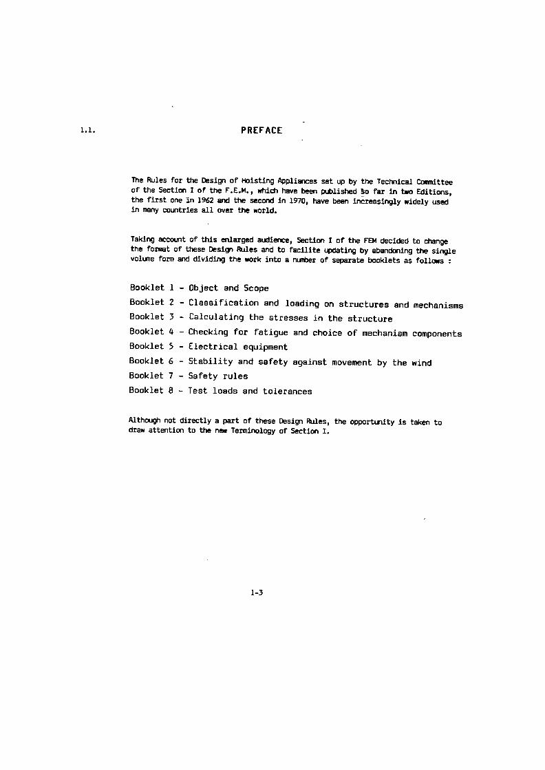
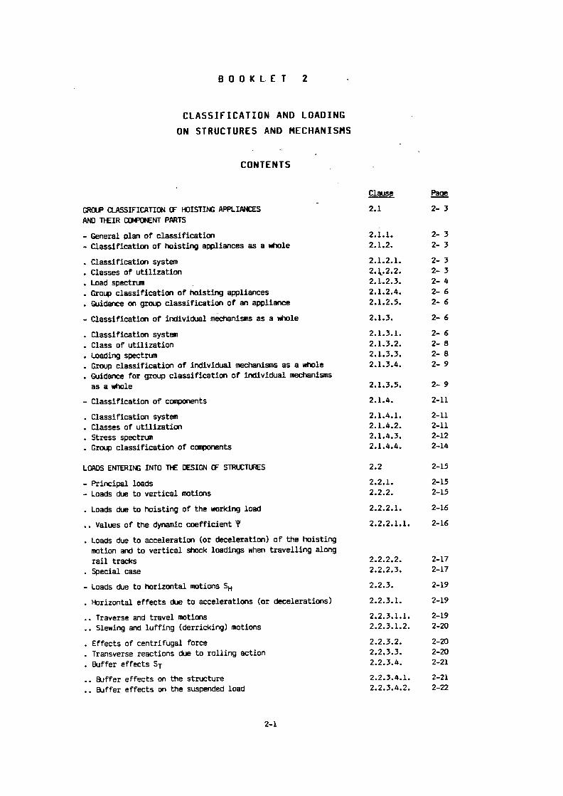
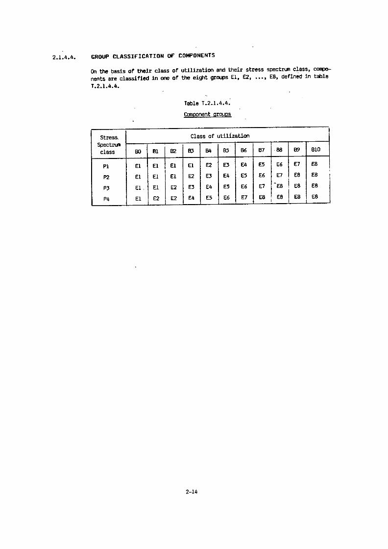
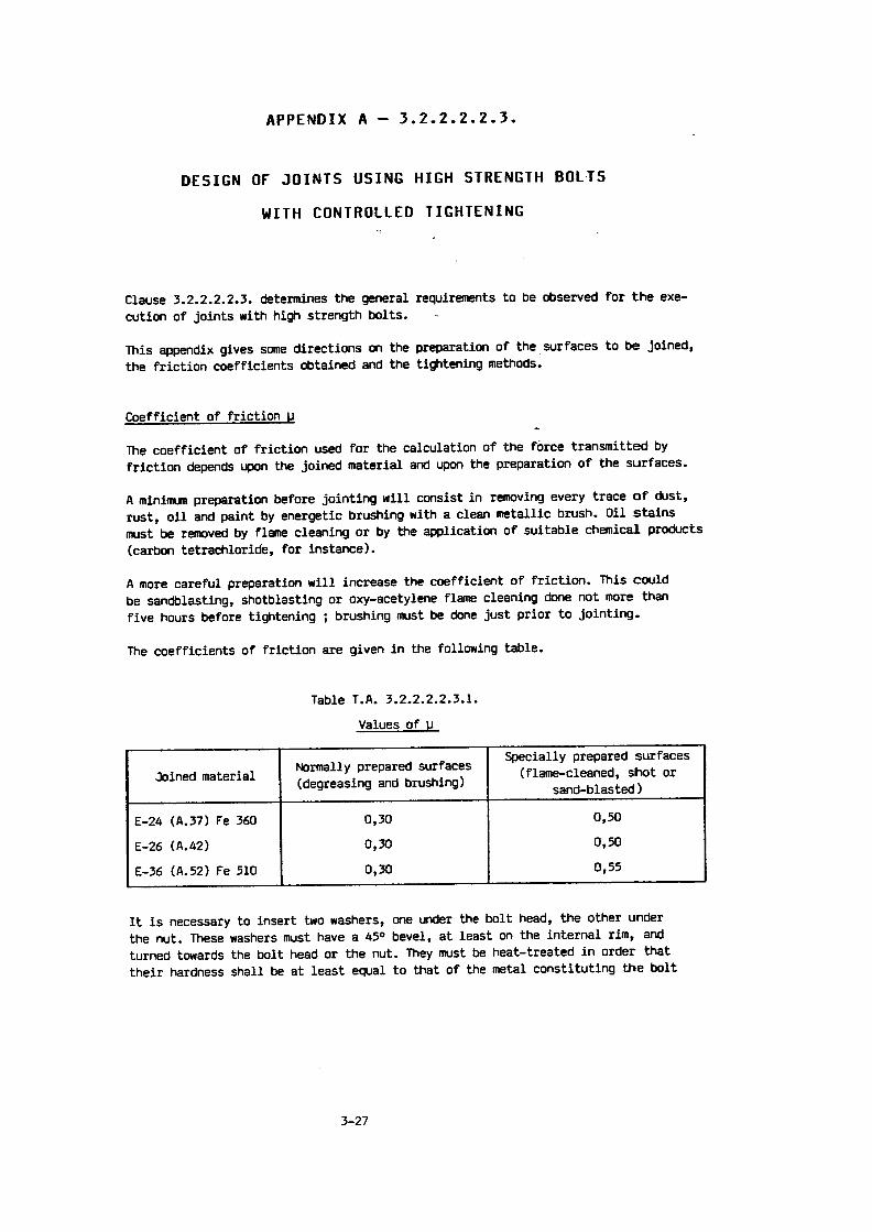
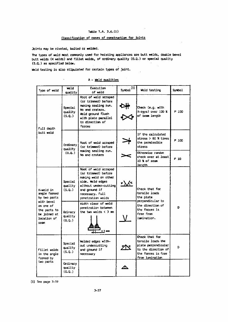
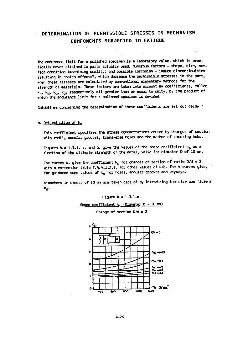
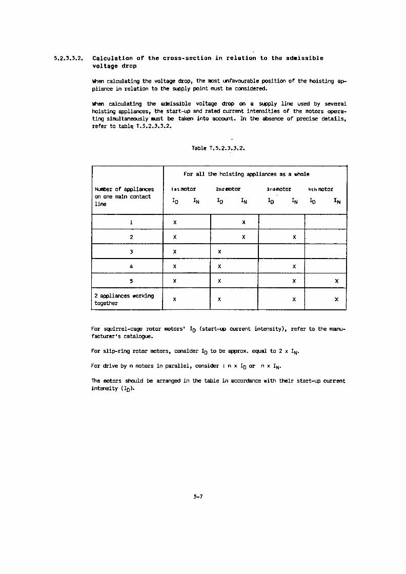
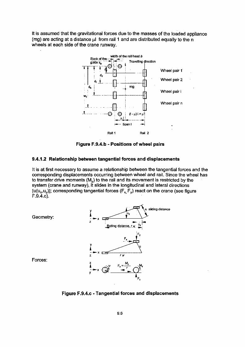
Scope of application and purpose
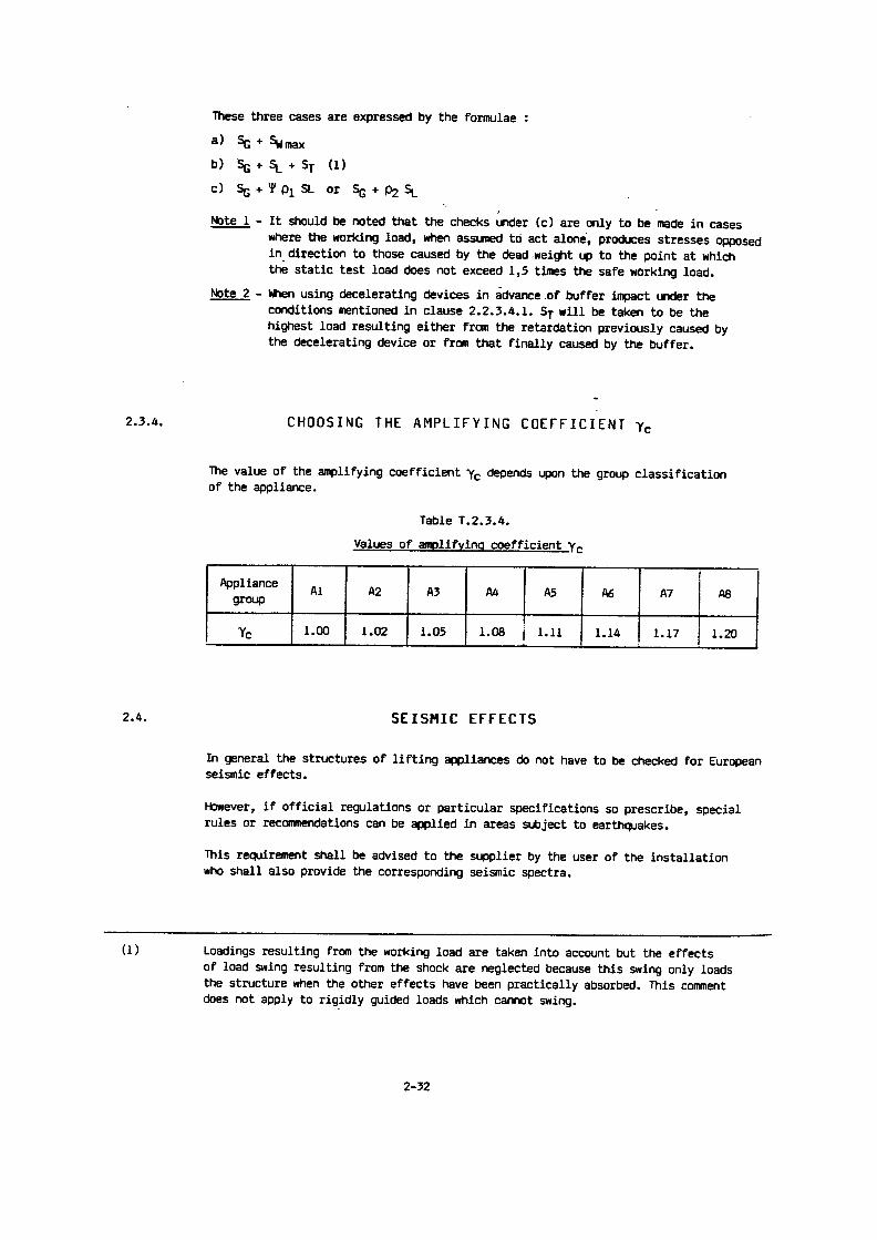
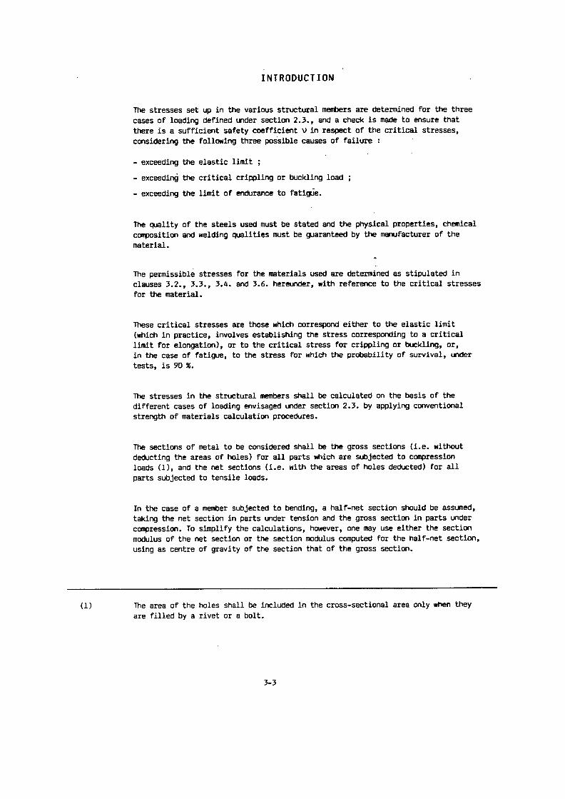
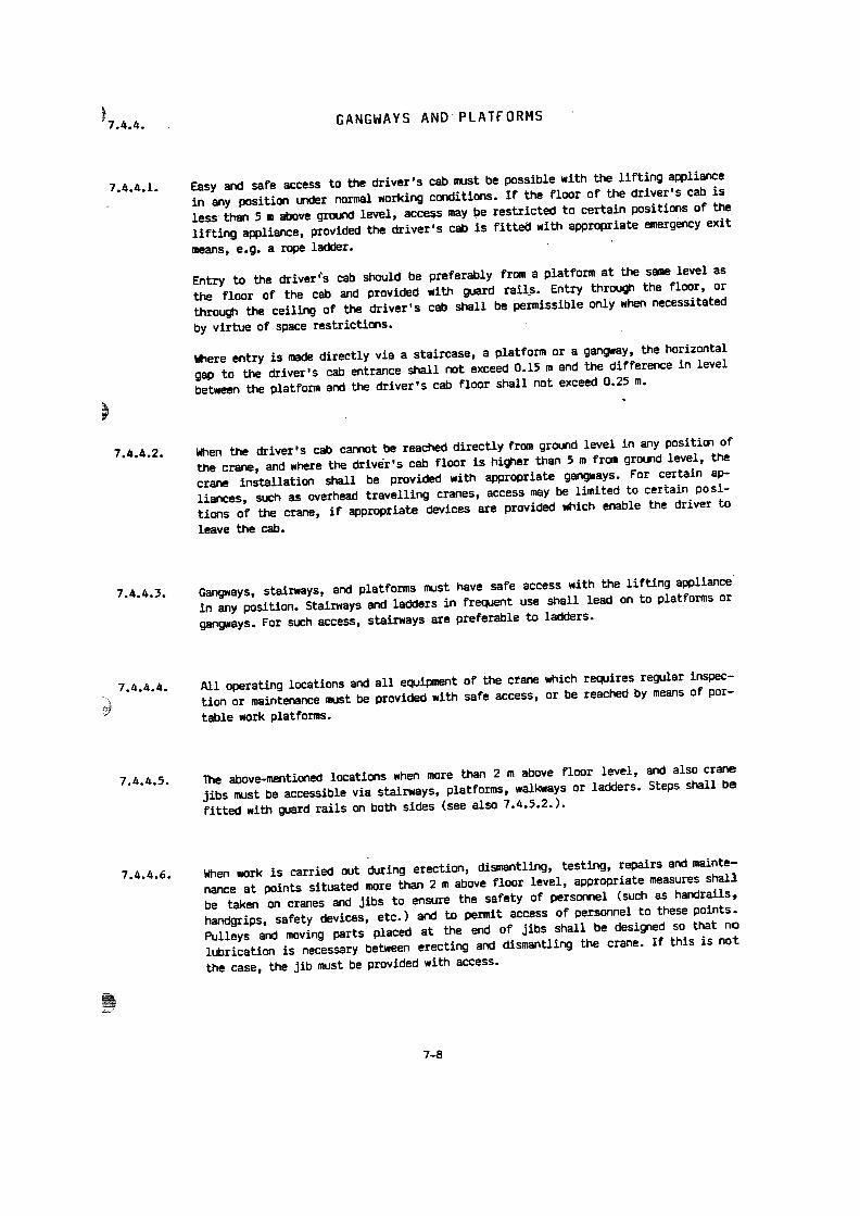
Graphical symbols for control devices
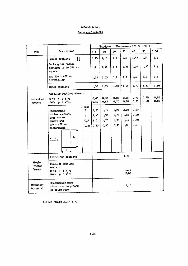
This rule contains In the table hereafter symbols for the text-free marking of control devices for floor-operated lifting appliances.
2 Size
All symbols can be varied according to space available . However, the recognizability compared to theshown size should be taken into account.
3 Execution
The symbols should be attached in such a way that they will be permanent and cannot be wiped off.The shape of the background on which arrows and symbols are attached is indifferent .
4
Arrangement of the symbols on the control devices
The symbols can be arranged on or beside the control devices . The symbol No. 9 (signal) may alsobe arranged turned by 90° .
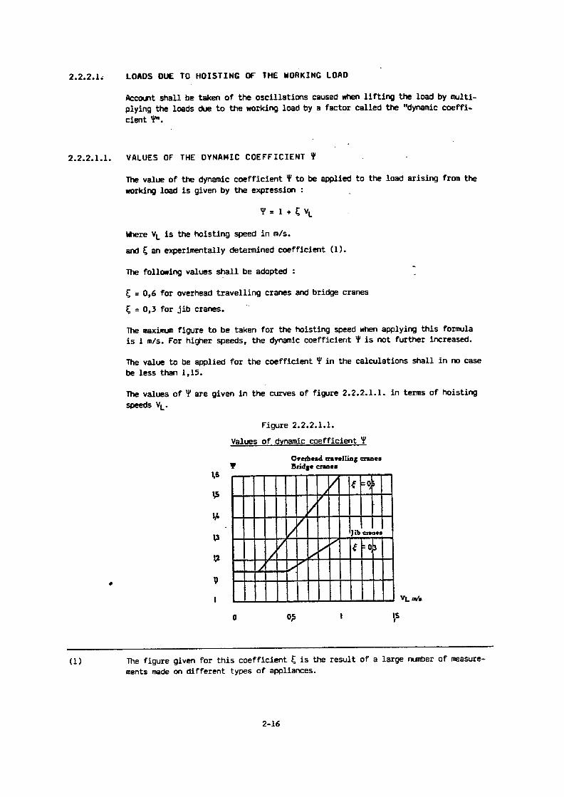
5
Instructions for application
In addition to the logically arranged arrows, control devices for opposed directions of movement mustbe distinguished by selection of inverted colours for the background and for the symbol .
For the switching of two different speeds there are two possibilities :
FEM9.941
a) Each speed is controlled by a different control device ; two arrows are used for the higher speed .
b) In the case of the so-called step switching, pressing the control device switches on first the slowand then the fast speed. The sign for this switching consists of two arrow heads arranged onebehind the other.
Crane travel movements away from and towards the operator are indicated by inclined arrows .
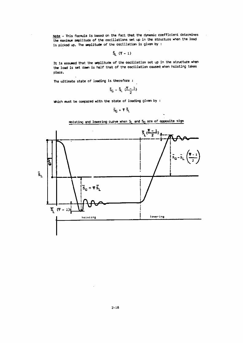
6
Instructions concerning the direction of crane and trolley movements
2nd edition (E)01 .1995
If the crane or the trolley Is provided with direction symbols, the following requirements must be met :
- The direction symbol must be clearly visible forthe the crane operator within the working area of thecrane and must be securely attached .
- The symbols on the crane and on the trolley must be analogue to those of the control device . Thesymbols indicated in the following table should be preferably used.
FbdeirationEuropeennedelaManutention(SectionIX)continued onpage 2
Copyright by FEM Section IX
Avallabla in English (E), French (F). German (D)
Sources of supply see back page
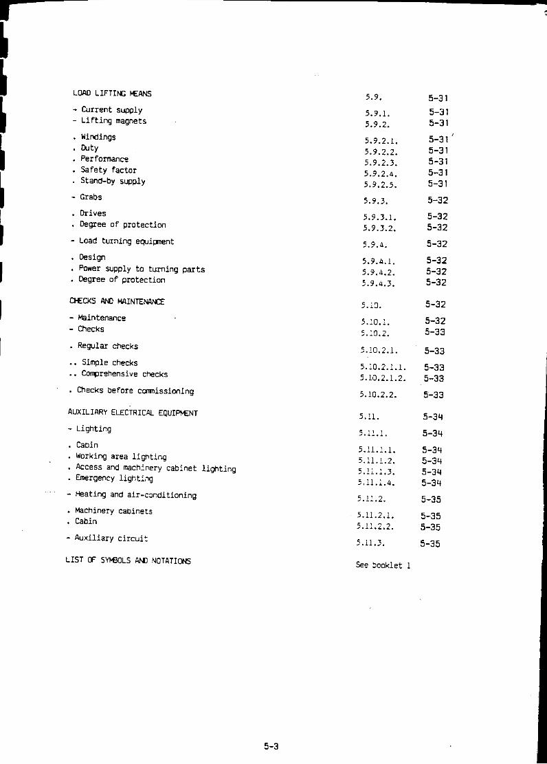
Short-time duty
FEM 9.683
Page 7
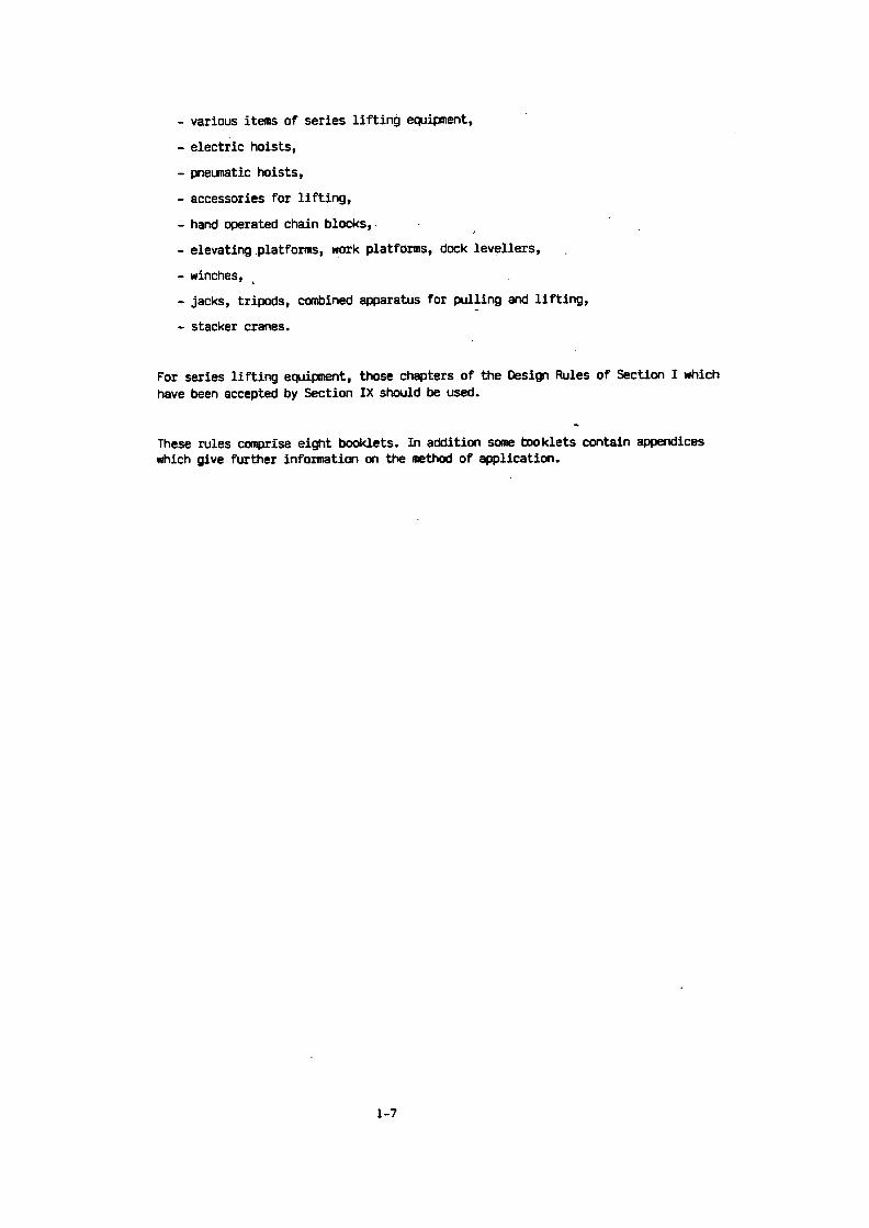
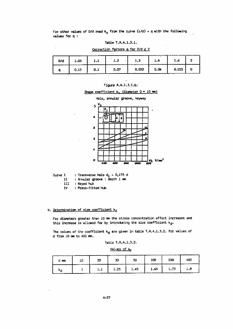
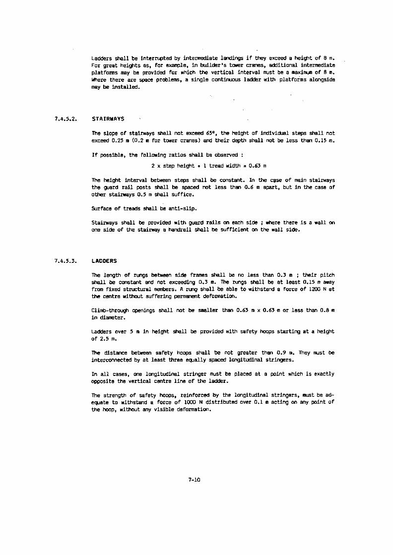
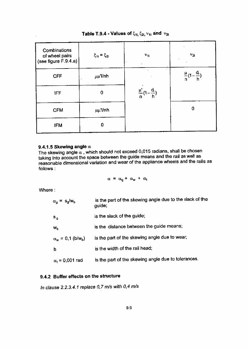
Under special conditions of duty (e.g . long travel of hook, the operating time may only be such that per-missible limit temperatures are not exceeded . In such cases, short-time duty is allowed instead of in-termittent duty. In this duty type, a lifting motor that has cooled down to the temperature of the cooling me-dium can be operated for a certain time with the load corresponding to the particular group of mecha-nisms . Minimum values for operating time of high speed and low speed windings' are given in table5.8.2.2.a for the various groups of mechanisms . No more than 10 starts may take place during this ope-rating time .
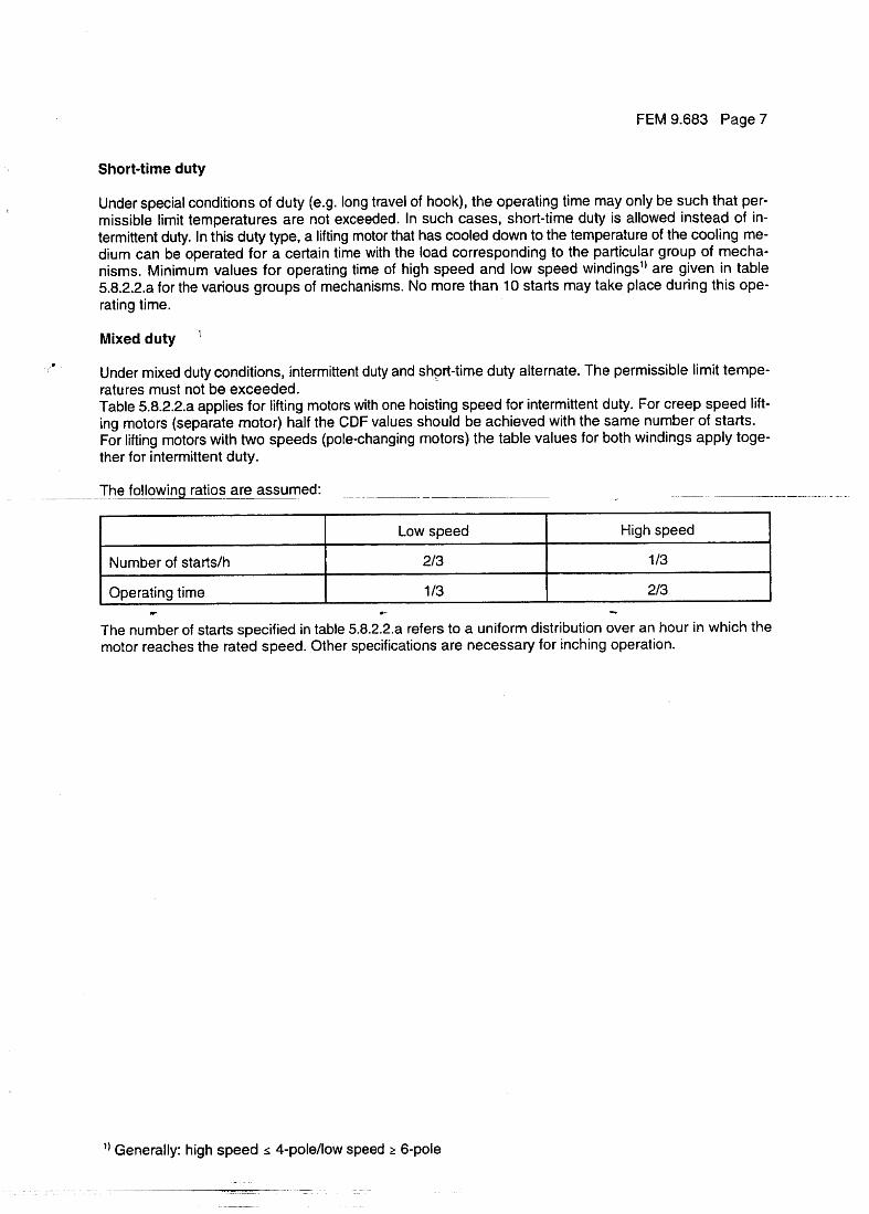
Mixed duty
Under mixed duty conditions, intermittent duty and sho_ rt-time duty alternate . The permissible limit tempe-ratures must not be exceeded .Table 5.8.2.2.a applies for lifting motors with one hoisting speed for intermittent duty . For creep speed lift-ing motors (separate motor) half the CDF values should be achieved with the same number of starts .For lifting motors with two speeds (pole-changing motors} the table values for both windings apply toge-ther for intermittent duty .
The following ratios are assumed:
Generally : high speed s 4-pole/ low speed >_ 6-pole
The number of starts specified in table 5.8.2.2.a refers to a uniform distribution aver an hour in which themotor reaches the rated speed. Other specifications are necessary for inching operation .
Low speed High speed
Number of starts/h 213 113
Operating time 113 213
Page 6 FEM 9.683
5.8.2 Motors for vertical motions5.8.2.1 Determination of required torquesFor a hoisting motor, the required powerto raise the maximum nominal Load (Pnmax) is defined in kW intaking account of the configuration of the gear transmission ratio and of the reeving according to the fol-lowing formula :
This results in the required torque to raise the maximum nominal load M Nmax in Nm:
P Nmax ' 9550 MNmax'
wheren : rotating speed of the motor in rpm
P Nmax
where :L : maximum nominal permissible lifting force in NV L :lifting speed in m/srl : efficiency of machinery
The manufacturer must ensure that the torque required far acceleration, for lifting the test load or to covervoltage and frequency tolerances are available .
The mechanical braking torque must be specified such that safe and reliable braking is ensured .If fitted, an electrical braking arrangement must be able to slow down the load in complete safety .
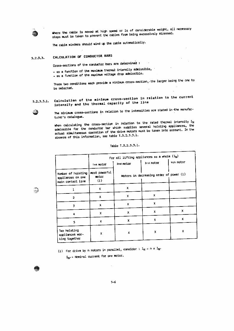
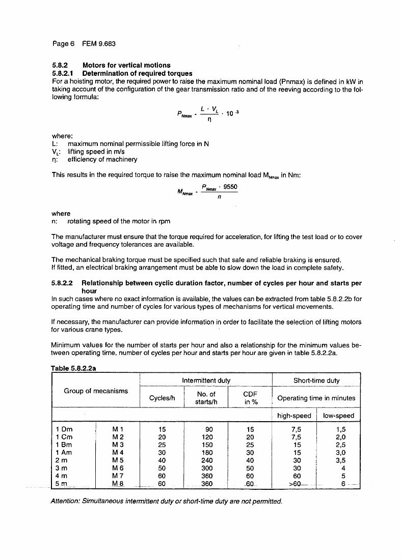
5 .8.2.2 Relationship between cyclic duration factor, number of cycles per hour and starts perhour
In such cases where no exact information is available, the values can be extracted from table 5.8.2.2b foroperating time and number of cycles for various types of mechanisms for vertical movements .
If necessary, the manufacturer can provide information in order to facilitate the selection o ¬ lifting motorsfor various crane types .
Minimum values for the number of starts per hour and also a relationship for the minimum values be-tween operating time, number of cycles per hour and starts per hour are given in table 5.8.2.2a .
Table 5.8.2.2a
Attention : Simultaneous intermittent duty or short-lime duty are not permitted.
Intermittentduty ~ Short-time dutyGroup of mecanisms ~ No. of CDFCycleslh starts/h in % ~ operating time in minutes
j high-speed I low-speed
1 Dm M 1 15 90 15 7,5 1,51 Cm M 2 20 120 20 l,5 2,01 Bm M 3 25 150 25 15 ; 2,51 Am M 4 30 180 30 15 ~ 3,02 m M 5 40 240 40 30 3,53 m M 6 50 300 50 30 44 m M 7 60 360 60 60 55_ m _ _ M 8 60_ . ._ 360 _ _60 . >60 _ . ~ _ ____ .__._ _ . g

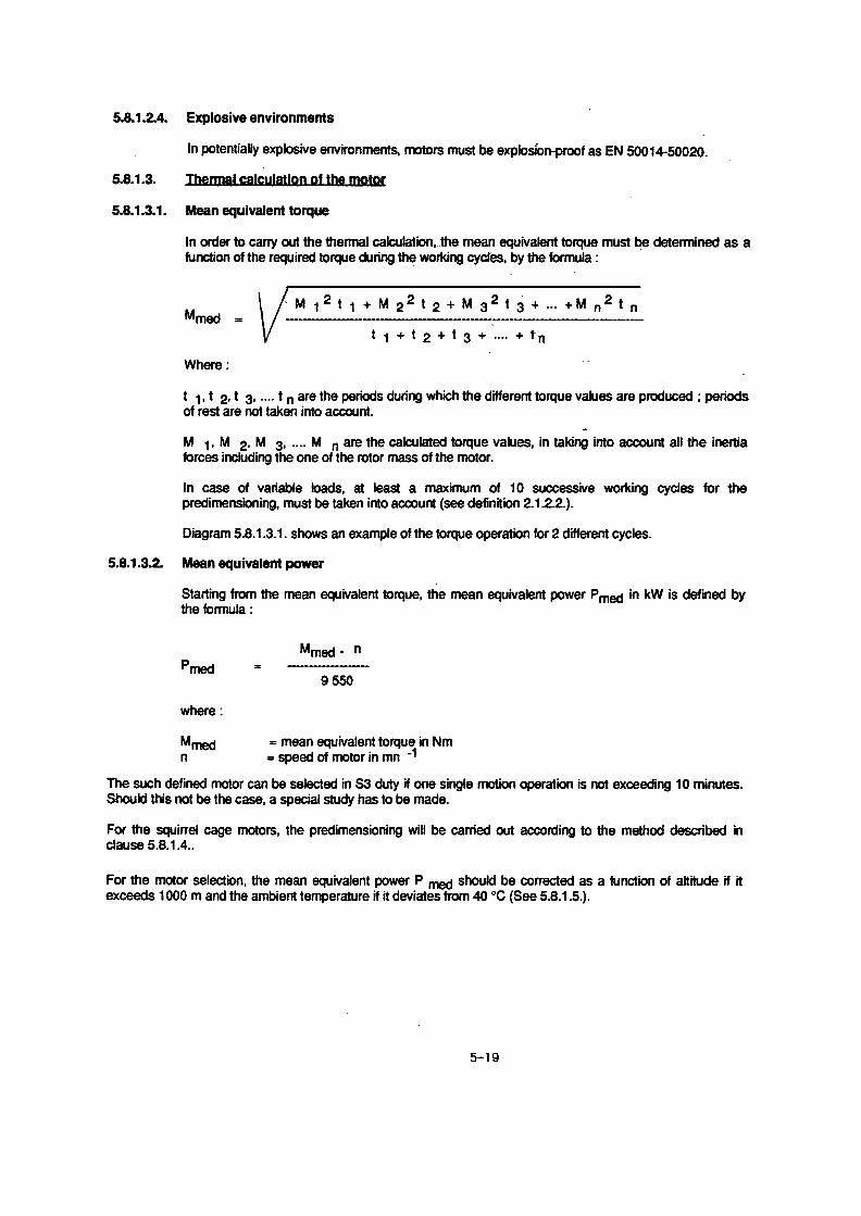
5.8.1 .3.2 Mean equivalent power
where :
M med =
mean equivalent torque in Nmn
=
speed of motor in rpm
Starting from the mean equivalent torque, the mean equivalent power Pmed inla :
Pmed =M w - n9550
The such defined motor can be selected in S3 duty if one single motion opernutes.
Should this not be the case, a special study has to be made.
For the motor selection, the mean equivalent power Pored should be correcteexceeds 1000 m and the ambient temperature if it deviates from 40° C oraccordance with 5.8.1 .5 .
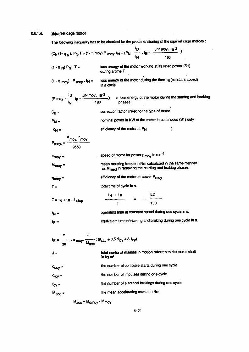
5.8.1 .4
Thermal calculation of squirrel-cage motors without frequenSpecifications regarding starting frequency must be given by the manufacturin para 5.8.2 .2 and 5.8.3,2 .
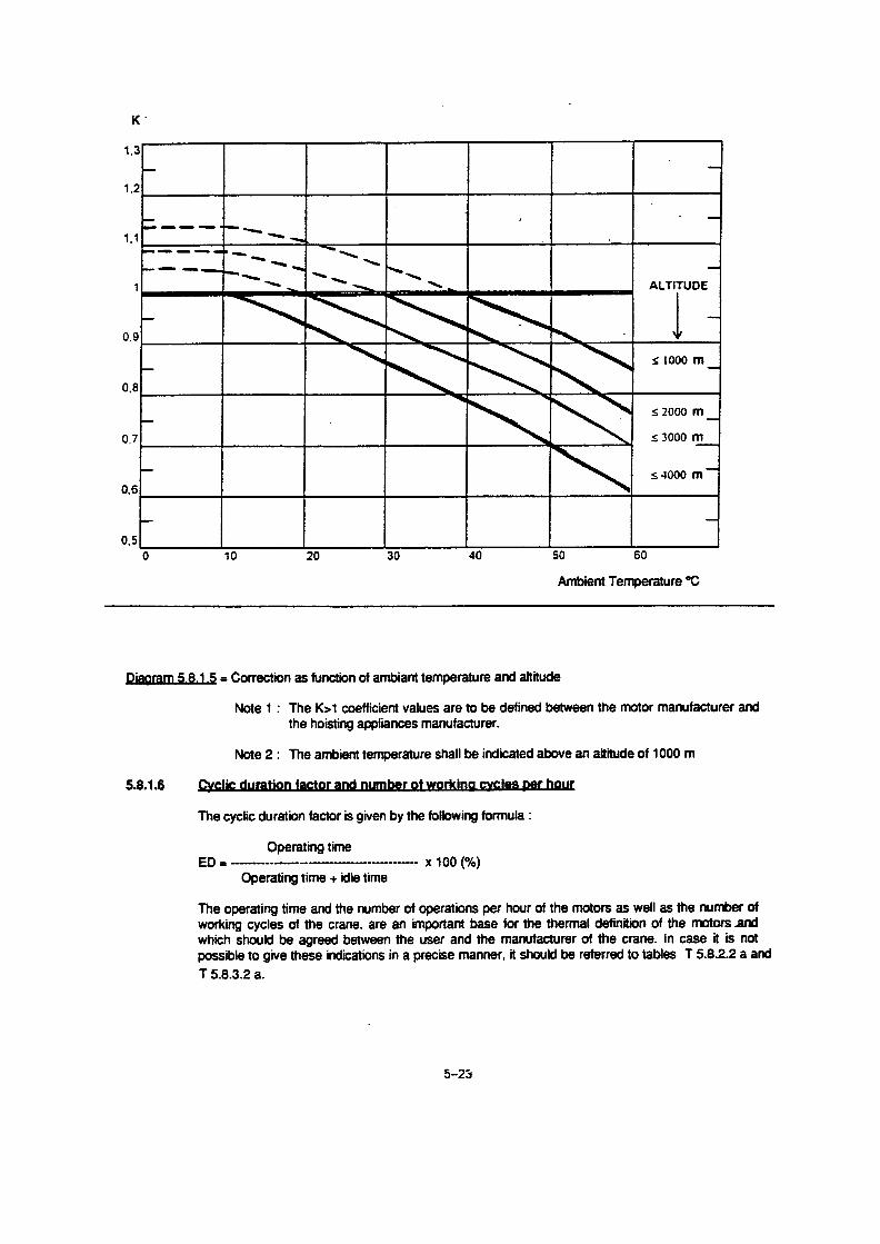
5.8 .1 .5
Power correction as a function of cooling agent temperaturThe motor output powers given in the manufacturer's tables apply far dutywith !EC 34-1, namely for :
Rated voltageRated frequencyAmbient temperature 40° CSite altitudes up to 1000 m above sea level
At ambient temperatures above 40° C and/or altitudes higher than 1000values of the motors must be adjusted accordingly . Depending on the conwer, CDF or starting frequency are reduced, if the motors would otherwiseperature rise limit .
5.8.1.6Cyclic duration factor and number of cycles per hourThe operating time can be calculated for a drive in accordance with the fo
based on a 10 minute cycle .
CDF =
operating time
X 100operating time + idle time
The operating time and the number of operations per hour of the motors asof the crane are an important basis for the thermal definition of the motorbetween the user and the manufacturer of the crane . In case it is not possia precise manner, refer to tables 5.8.2.2.b and 5.8.3.2 .b .
FEM 9.683 Page 5
kW is defined by the formu-
ation does not exceed 10 mi-
d as a function of altitude if itrestrictions must be stated in
cy inverter controler . Minimum values are given
e and altitudetypes defined in accordance
m above sea level, the ratedditions of application, the po-exceed their permissible tem-
llowing equation :
well as the number of cycless and which should be agreedble to give these indications in

Page 4
FEM 9.683
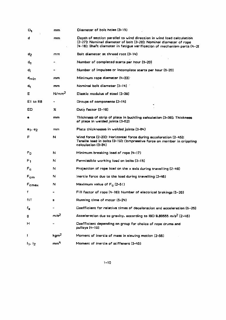
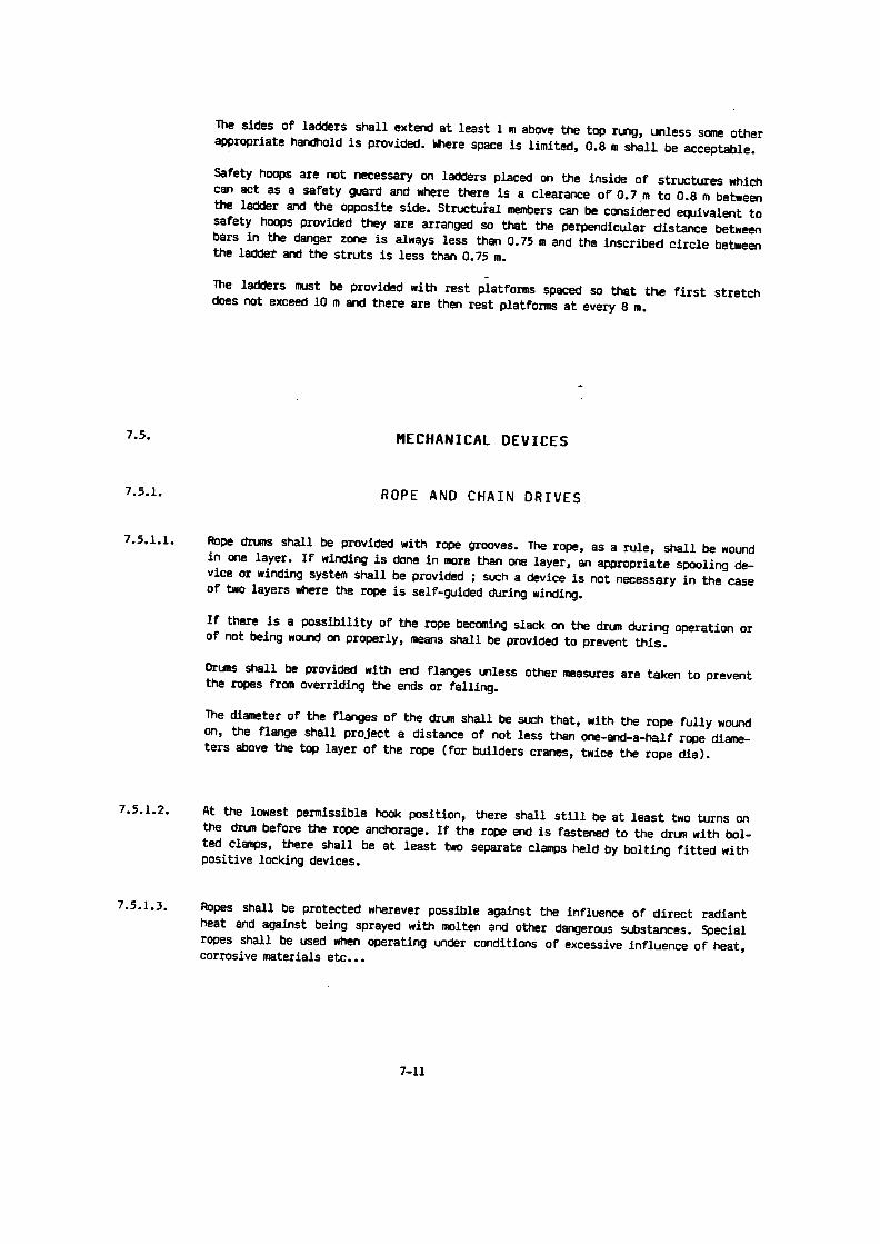
liftingmotion
horizontalmotion
liftingmotion
horizontalmotion
lifting
loweringwith rated load.,
,, with rated load
lifting with
lowering withpartial load _ ,
, _
partial load
Lifting motion. .__tr. idle times
_
_
_ _ .
_
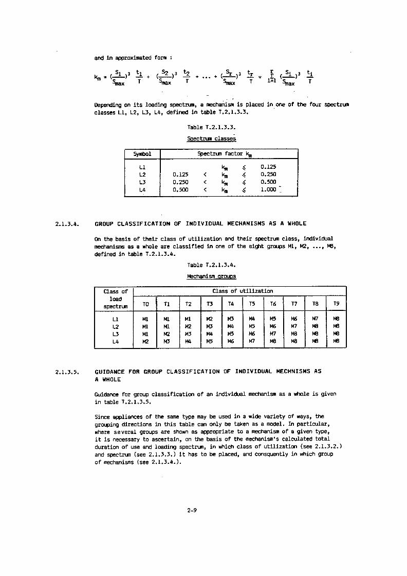
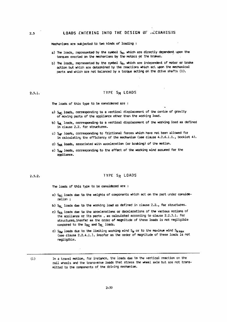
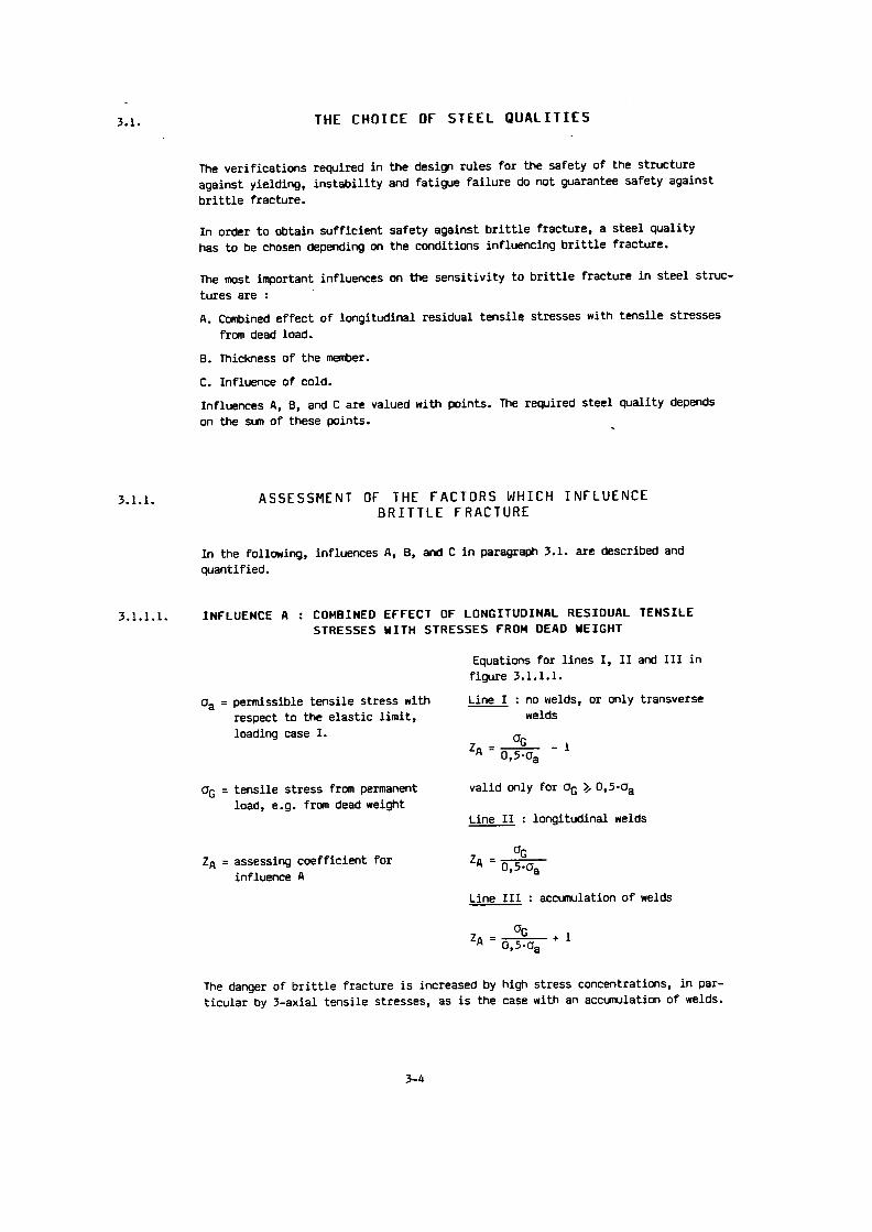
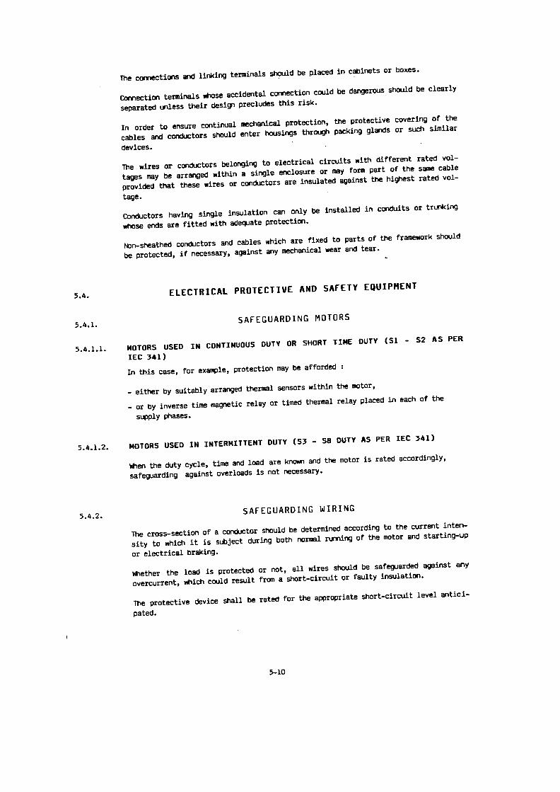
M,,M4, M7, M10 = acceleration torqueM2, M8 = torque when lifting
M3 , M6, M9, M12 = braking torqueM5, M11 = torque when lowering
lifting loweringwithout load
without load
liftingwithout load
Diagram 5 .8.1 .3 .1Torque variation for two different load cycles
loweringwithout load
time
lime
Horizontal motiontr = idle timesM,, Ma = acceleration torqueM2 = torque with load and resisting windM3, M6 =_braking torqueMS = torque without load and with driving wind
Where:
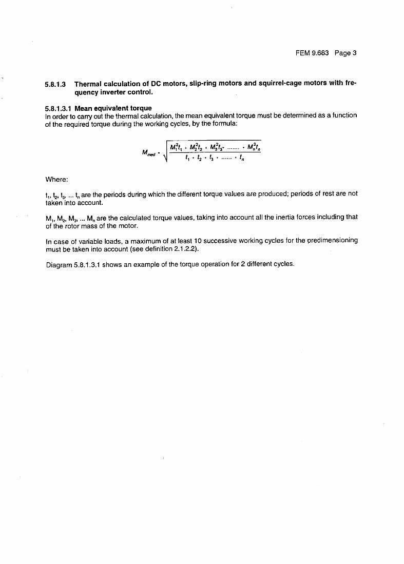
5.8.1 .3
Thermal calculation of DC motors, slip-ring motors aquency inverter control .
5.8.1 .3.1 Mean equivalent torqueIn order to carry out the thermal calculation, the mean equivalent torqof the required torque during the working cycles, by the formula :
M; r, + Mzr2 + M3r3+ . . . . . . .
+
med
M
t,, t2, t3 , . . . to are the periods during which the different torque values ataken into account.
M,, M2, M3 , . . . Mn are the calculated torque values, taking into accounof the rotor mass of the motor .
!n case of variable loads, a maximum of at least 10 successive wormust be taken into account see definition 2.1,2.2} .
Diagram 5 .8 .1 .3 .1 shows an example of the torque operation for 2 d
FEM 9.683 Page 3
nd squirrel-cage motors with fre-
ue must be determined as a function
nztn
re produced ; periods of rest are not
t all the inertia forces including that
king cycles for the predimensioning
ifferent cycles .

Page 2
FEM 9 .683
5.8.1 Criteria for motor selection (IEC 34-1)
required powers - the thermal power is also included in these required powers,maximum rated torque and maximum acceleration torque,cyclic duration factor,number of cycles/hour,type of control (type of braking),speed regulation, drive systemstype of power feed,degree of protection, (environment conditions),ambient temperature,altitude .
For the dimensioning of the motor, account has to be taken of :- the thermal calculation as per clause 5.8.1 .3.- the maximum required torque :
for hoisting mechanisms as per clause 5.8.2 .1 .for horizontal motions as per clause 5.8 .3 .1 .
The motor has to comply with both requirements .
If the required torque diagrams, in order to define the mean equivalent torque (as per 5.8.1 .3.1) are notavailable, these can be assessed with the help of tables 5.8.2.2 .b and 5.8.3 .2.b respectively .
5 .8 .1 .1 Remarks on the selection of motorsThe motors must be suitable for the operating conditions (criteria for motor selection 5.8 .1 ) and ensuresafe operation under related conditions .
In the event of electronic power control, the motors must be specified taking into account the cooling sys-tem and the speed range .
An external fan may be provided to increase the number of starts per hour and number of cycles perhour .
5.8.1 .2 Degree of protection (IEC34-5)5.8.1 .2 .1 Indoor applicationFor indoor application, under normal conditions, motors must comply with IP 23 at least .In dusty environment, motors must comply with ID 44 at least .
5.8.1 .2.2 Outdoor applicationFor outdoor application, motors must comply with IP 54 at least .In case of water condensation risk, care should be taken that the water condensation drain holes remainopen .
5.8,1 .2.3 Particular applicationMotors may comply with a lower degree of protection if they are appropriately protected, or protected byexternal means for their particular application .
5.8.1 .2.4 Explosive environmentsIn potentially explosive environments, motors must be explosion-proof as specified in EN 50014-50020 .

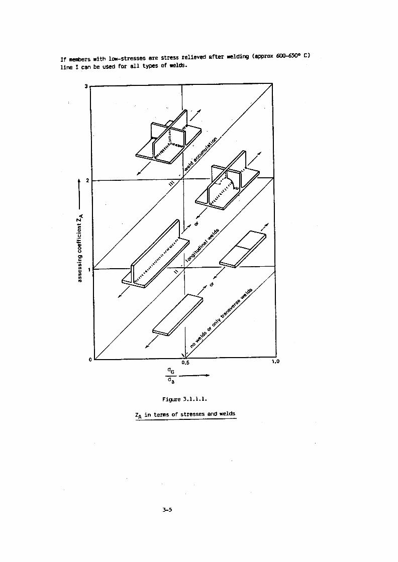
Introduction
FEDERATION EUROPEENNE DE LA MANUTENTION
Section IX
SERIES LIFTING EQUIPMENT
Selection of lifting and travel motors
This rule contains the selection criteria for lifting and travelling motors in series liftingequipment . Booklet 5 "Electrical equipment" revision 1992.10.01 of the rule FEM 1 .001 "Rulesfor the design of lifting appliances" (3rd edition : 1987.10.01) of the FEM-Section I "Heavy liftingappliances" served as a basis reference . This rule deviates from the booklet referred to abovein order to take into account the specific requirements of series lifting equipment .
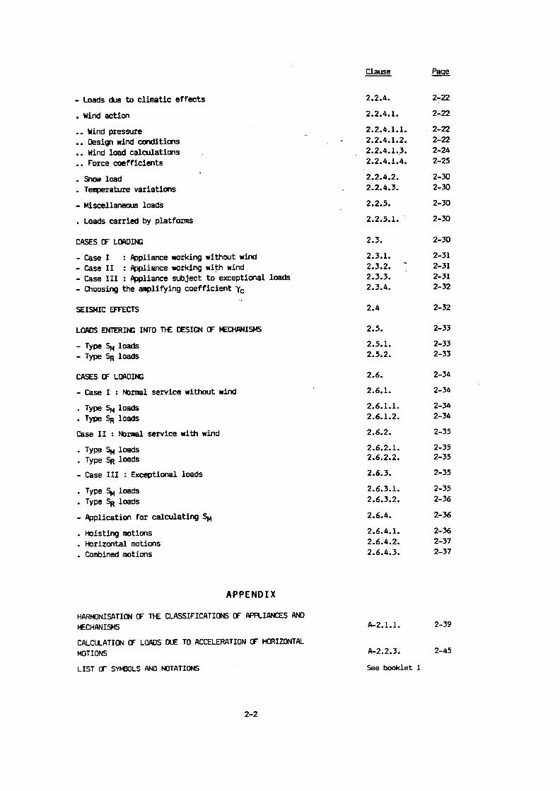
Contents
FEM9.683
10.1995 (E)
Federation Europeenne de la Manutention (Section IX)
Continued page 2 bis 13
_Available In English ._ ;_Sources gf supply see back page_
_
Page
5.8 Motor selection _5.8 .1 Criteria for motor selection (IEC 34-1) 25.8.1 .1 Remarks on the selection of motors 25.8 .1 .2 Degree of protection (IEC 34-5) 25.8 .1 .3 Thermal calculation of DC motors, slip-ring motors and squirrel-cage motors
with frequency inverter control . . . . . . . . . . . . . . . . . . . . . . . . . . . . . . . . . . . . . . . . . . . . . . . . . . . . . . . . . . . . . . . . . . . . . . . . . . . . . . . . . . . . . . . . . . . . . . . . . . . . . 35.8 .1 .3 .1 Mean equivalent torque . . . . . . . . .. . . 35.8 .1 .3.2 Mean equivalent power 55.8 .1 .4 Thermal calculation of squirrel-cage motors without frequency inverter control . . . . . . . 55.8 .1 .5 Power correction as a function of cooling agent temperature and altitude 55.8 .1 .6 Cyclic duration factor and number of cycles per hour 55.8 .2 Motors for vertical motions . . . 65.8 .2 .1 Determination of required torques . . . . . . . . . . . . . . . . . . . . . . . . . . . . . . . . . . . . . . . . . . . . . . . ., . . . . . . . 65.8 .2.2 Relationship between cyclic duration factor, number of cycles per hour and
starts per hour 65.8.3 Motors for horizontal motions - - - 95 .8.3.1 Determination of required torques . . . . . . . . . . . . . . . . . . . . . . . � . . . . . . . . . . . . . . . . . . . . . . . . . . . . . . . . . . . . . . . . . . . . . . . . . . . . . . . . . . . . ., . . . . . . . . . . . . . . 95 .8.3.2 Relationship between cyclic duration factor, number of cycles per hour and
starts per hour 105.8.3.3 Rotation 135.8.3.4 Span variation 13

Page 2
FEM 9.941 (01.95)
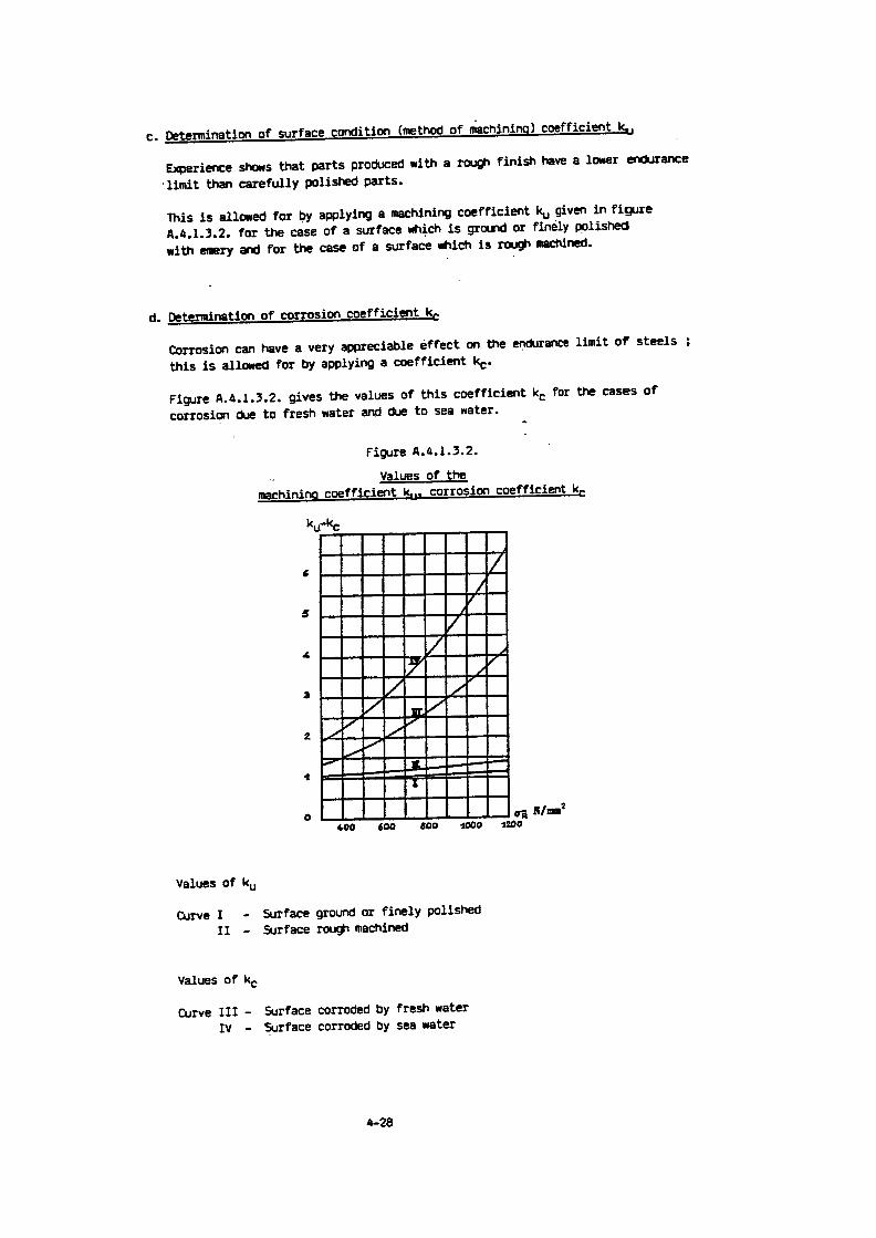
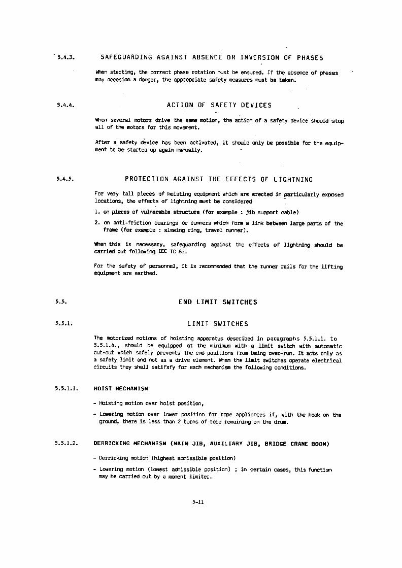
1 2 3 4 5 6 7
SymbolControl Speed Colour of the
with single switching with stepswitching
of to slow fast slow/fast Background Symbol
II=ON,/ F2 0II~
FA-M-1li'I1 up ~VW optional optional
except in contrastHoist red and to thedown 0 0 green background
3 right `I ~QI -LIFA- 10I
examples :Trolley
4 left 0 G 05 forward 1
FA-0 0l
,I
yellow black\!JI bare metal black
8
Crane
backward © 0 for opposite movementsinvert colours:
7 right ~~~ I~IrIQI
J ~-J LJblack yellowStewing black bare metalmechanism
8 left
9 Signal I',-I optionaloptional in contrast
A1except red to the
background10 on ,- "I
11 Crane switch off1). ..Irt.;.\
(Maincontactor) L-J optional
in contrastredr.1.;," 1) to the
2 on backgroundoff
Bridgingswitch f ~
I optionaloperational except redlimit switch -
1) Red Is Indicated by cross hatching

Page 8
FEM 9.683
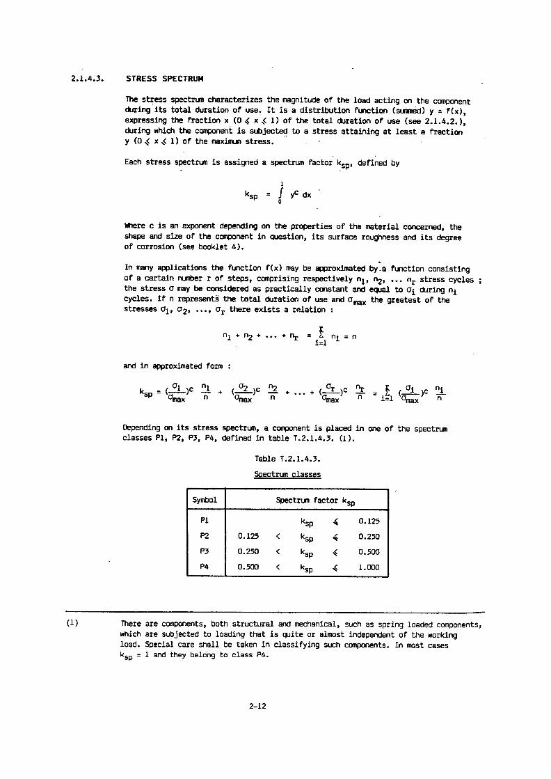
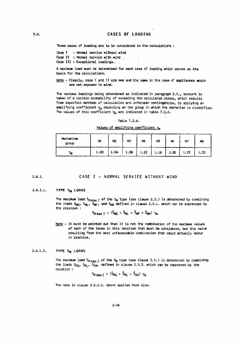
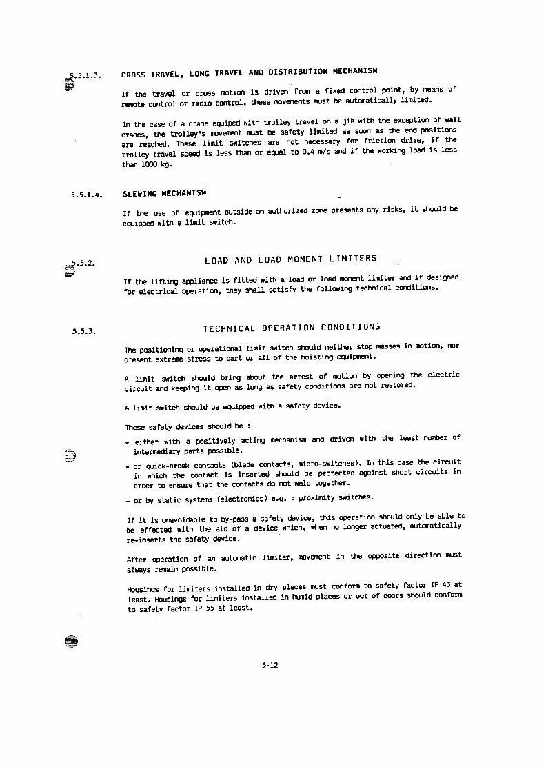
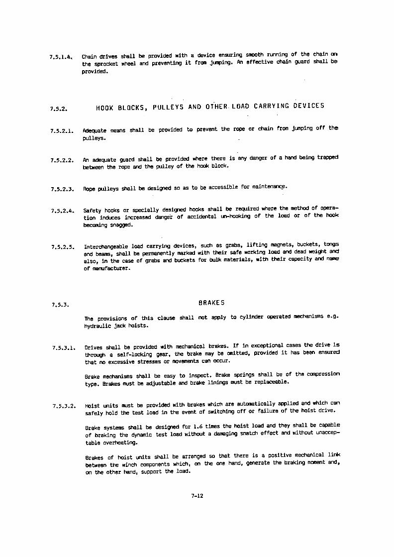
Table 5,8.2.2.bindications for the number of cycles per hour of the crane and the cyclic duration factor for the verticalmotions in %
1) This column comprises only same indicatary typical cases of utilisation2) It is recommended for S1 or S2 to refer to the definition IEC 34-1
Type of appliance Previsions conc. Number Type of mechanism CDF °l°the type o~ of cycles Derricking
Ref. Designation utilisation per hour Lifting ~ hingedDerricking
boom boom
1 A liance with manual drive ~2 ~ Jib cranes for assemblin 2 - 25 25 - 40 ~ 253
_ ._Assembling and dismantling 2 - 1 5 15 - 40cranes for power stationsmachine silo s . . .
4 Stacking and reclaiming Hook 20 - 60 40 ~ S2-traps orters ~ 15/30min2)
5 Stocking and reclaiming Grab or magnet 25 - 80 60 -100 S2-trans orters 15/30min2)
6 Worksho cranes 1 D - 50 25 - 407 Overhead travelling cranes, Grab or magnet 40 -120 40 -100
Pi breakin cranes 60Scra char in cranes ! _
8 Ladle cranes 3 - 10 40 - 609
_Soakin it cranes 30 - 60 40 - 60
10 Stripper cranes, open hearth 30 ~60furnace char in cranes 10 60 ___
11 For e cranes 6 40 _____12.a Unloading bridge cranes, Hook or spreader 20 - 60 40 - 60 S2-
Bridge craines for containers 15/30min2)F
12.b Other bridge cranes with crab Hook 20 - 60 40 - 60 S2-and/or rotatin crane 15/34min2) ~ __
13 Unloading bridge cranes, Grab or magnet 20 - 80 ~ 40 -100 i S2-Bridge cranes with crab ~ 15/30min2)and/or rotain crane 60
14 Shipyard jib cranes, Hook 20 - 50 40 40Dismantlin jib cranes
15 ~ Wharf cranes (rotating on Hook 40 60 ~ I 40 - 60bridge crane. . .floating cranes and 20 40shear le s
16 Wharf cranes rotating on Grab or magnet 25 - 60 60 -100 40 - 60bridge crane. . .)floating cranes andshear le s
17 Floating cranes and shear ~ 2 - 10 S1or S2legs for heavy lifts usually S2-3D min2) 15130 min2)> 100 t
18 Deck cranes I_ Hook 30 - 60 40 4019 Deck cranes Grab or ma net 30 - 80 60 I 60
20 Site tower cranes 20 40 - 60 j 25 - 4021 Derrick cranes 10 ~ S1 or ~ S1 or
S2-30min2) I S2-30min2)
22 ~Railway cranes, admitted for 10 40_ .ilwa traffic _ _ . _

Page 12
FEM 9.683
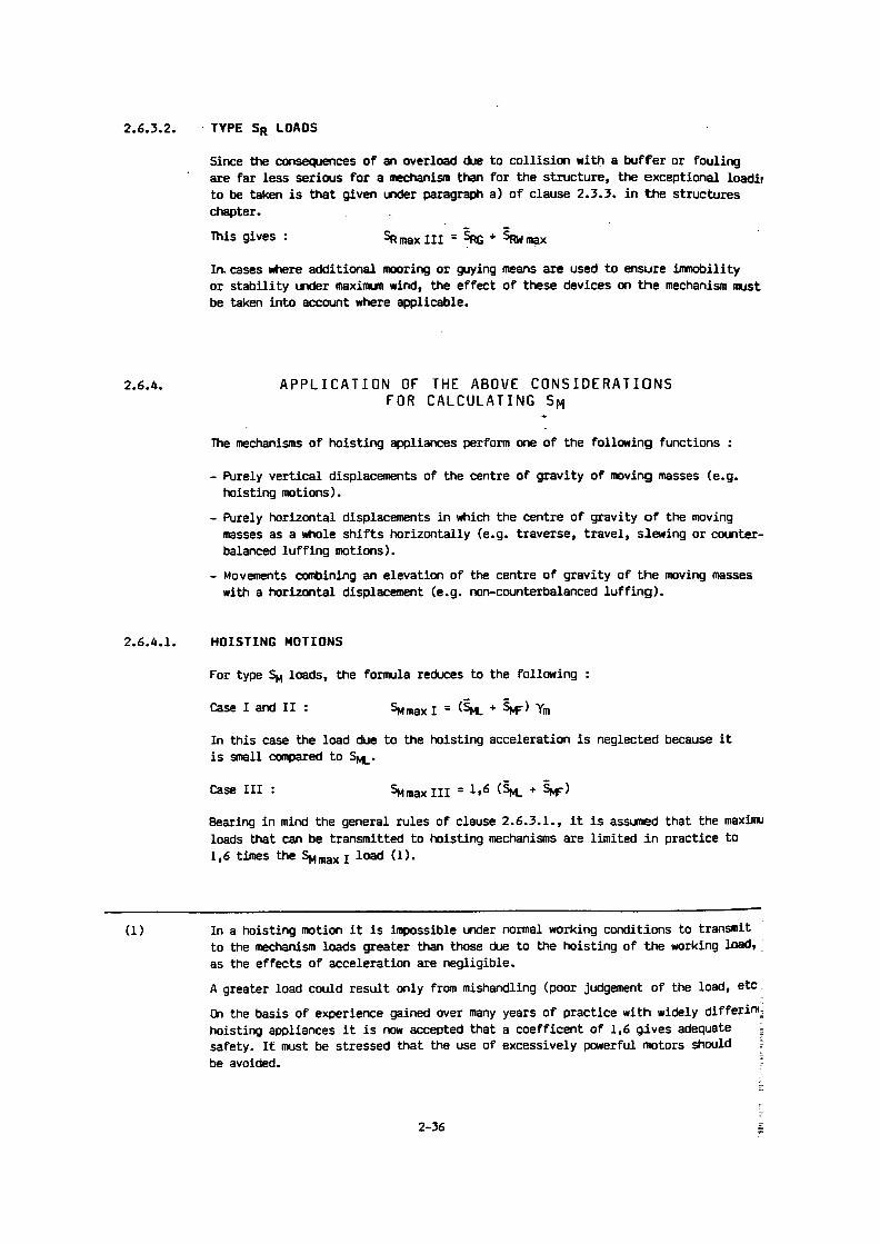
Table 5.8.3.2.b
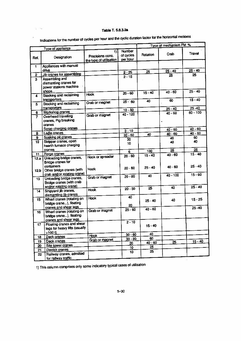
This column comprises only some indicatory typical cases o u i isa ion
Indications forthe number of Ies r hour of the crane and me lic duration factor for the horizontal motinsmotions in %
Type of apliance f Previsions cone . .~ Number of ,
Type of mechanism CDF %
the type ofutilisation 1) cycles per ' ' Derricking i Derricking
Ref. Designation hour Lifting hinged ibbom
i ~ boom ~
1 Appliance with manual drive ~ j ~2 Jib cranes for assembling 2 - 25 25 ~ 25 - 40 25 - 403 Assembling and dismantling 2 - 15 25 ~ 25
cranes for power stationsmachine shops . . .
4 Stocking and reclaiming Hook_
20 - 60 15 '- 40 40 - 60 25 - 40transporters _
5 Stocking and reclaiming Grab or magnet 25 - 60 40 ~ 60 15 - 40transporters ',,
6 Workshop cranes 10 - 50 25 - 40 25 - 407 Overhead travelling cranes, Grab or magnet 40 -120 40 - 60 ~ 60 -100
Pig breaking cranesScrap charging cranes
i
8 Ladle cranes 3 - 10 j 40 - 60 40 - 60
9 Soaking pit cranes 30 - 60 4D I 40 - 60 ~ 40 - 6010 Stripper cranes, open hearth ~ 3D ; 40 ` 60
furnace charging cranes ~ 10 ; 40 - 40
11 Forge cranes 6 ~ 10D f 25 25
~12 .a Unloading bridge cranes, Nook or spreader 20 - 60 15 - 4D40 - 60 ~ 15 - 40
Bridge cranes for containers
12 .b Other bridge cranes with crab Hook 20 - 6025 - 40 ~ 40 - 60 25 - 40andlor rotating crane
13 Unloading bridge cranes, Grab or magnet ' 20 - 80 4D ~ 40 - 100 15 - 60Bridge cranes (with crab andlor irataing crane)
14__
Shipyard jib cranes, Hook 20 - 50 25 40 25 - 40
Dismantling jib cranes15 Wharf cranes rotating on Hook 40 25 - 40 40 ~ 15 - 25
bridge crane . . .floating cranes and 2D j 'vshear legs
', ! t
16 Wharf cranes (rotating on Grab or magnet 25 - 60 ~ 40 - 60 ~ ! 25 - 4Dbridge crane . . .)floating cranes and i ~shear legs
17 Floating cranes and shear legs 2 - 10 15 - 4D ~for heavy lifts usually> 100 t)
18 Deck cranes Hook I 30 - 60 ; 40 j19 Deck cranes Grab or magnet ~ 30 - 80 ~ 6D20 Site tower cranes I 20 ~ 40 - 60 25 I 15 - 4021 ~ Derrick cranes
1025
22 Railway cranes, admitted for 10 ~ 25'railwa traffic _ _ _ _ ._ __ ~ __ __ _- __ ___ ______ _
" f tili t'

Table 5.8.3.2.a
Attention :
Simultaneous intermittent duty or short-time defy are not permitted.
Short-time duty
FEM 9 .683 Page 11
Under special conditions of duty (e.g . long travel of hoak), the operating time may only be such that per-missible limit temperatures are not exceeded . In such cases, short-time duty is allowed instead of in-termittent duty. In this duty type, a lifting motor that has cooled down to the temperature of the cooling me-dium can be operated for a certain time with the load,
Minimum values for operating time of high speed and low speed windings are given in table 5.8 .3.2.a forthe various groups of mechanisms . No more than 10 starts may take place during this operating time'.
Mixed duty
Under mixed duty conditions, intermittent duty and short-time duty alternate . The permissible limit tempe-ratures must not be exceeded .
Table 5.$ .2.2.a applies for lifting rnotors with one hoisting speed for intermittent duty .For travel motors with two speeds, the values for both windings apply together .
The following ratios are assumed :
The number of starts specified in fable 5.8.3.2.a refers to a uniform distribution over an hour in which themotorreaches the rated speed. Other specifications are necessary for inching operation.
1) Generally : high speed <_ 4-pole / low speed >_ 6-pole
Intermittent duty Short-time dutyGroup of
mechanisms Cycles/h No . of CDF Operating time in minutesstartsl/ in %
high-speed low-speed
1 Dm M 1 10 60 10 10 1,51 Cm M 2 15 90 15 10 2.01 Bm M 3 20 120 20 15 2.51 Am M 4 25 150 25 15 3.02 m M 5 30 184 30 30 3 .53 m M 6 40 240 40 30 44 m M 7 50 300 50 60 55 m M 8 >60 >360 60 > 60 6
Lowspeed High speed
Number of starrs/h 213 113
Operating time 1l3 2l3

22
Page 10 FEM 9.683
where ;
Wo, W8, W25: total travel resistance in N (in certain operating situations,zero
W may be negativeW o at speedW a at a wind of 80N/mW 25 at a wind of 250N/m
v travel speeds in m/sn ; rotation speed of motors in rpm0 : overall efficiency of mechanismm : equivalent mass in kg of all parts put into motion, excluding the load, which is assumed to
be concentrated at the suspension point of the load .m=mo+mrot,'rl
m o : mass in kg of the whole of the elements, excluding the load, undergoing the samehorizontal motion as the suspension point of the load .equivalent mass in kg of the rotating parts referred to linear motion .
The inertia of the rotating masses referred to linear motion is evaluated using the formula :
where :
acceleration in m/s2 (at constant speed a = O)mass of useful load in kg
2moor ° 1 '91,2 v
,! moment of inferno of all rotating masses in kgm2n : speed of rotating masses in rpm
For determining the maximum torque of the motor, the highest calculated torque value shall be taken intoaccount .
For slip-ring motors used for the horizontal motions, the starting resistances shall be so defined that theminimum torque supplied by the motor is never less than 1 .2 times the torque required to maintain the tra-vel speed .
5.8.3.2 Relationship between cyclic duration factor, number of cycles per hour and startsper hour
In such cases where no exact information is available, the values can be extracted from table 5 .8.3 .2.bfor cyclic duration factor and number of cycles for various types of mechanisms for horizontal mo-vements . If necessary, the manufacturer can provide information in order to facilitate the selection oftravel motors for various crane types .
Minimum values for the number of starts per hour and also a relationship far the minimum values be-tween cyclic duration factor, number of cycles per hour and starts per hour are given in table 5.8 .3.2.a .
In practical operation, a lower number of cycles can also occur in the lower groups at the given numberof starts and a higher number in the higher groups, for instance when operation is automated . If travelmotors are used in the short-time made, e.g . where the travel distances are long, there must be no morethan 10 starts . Minimum values for the operating time for the various groups of mechanisms are given intable 5.8.3 .2.a .
5 .8,3.1
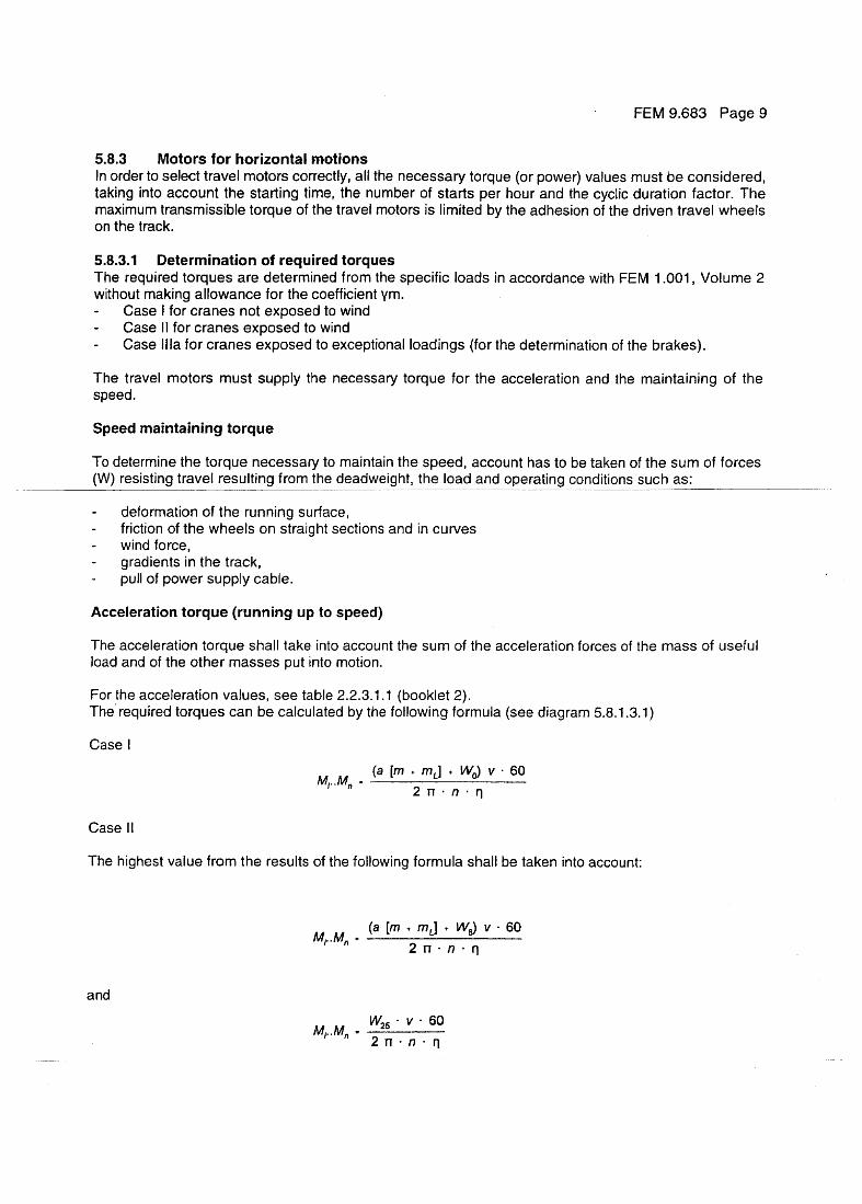
Determination of required torquesThe required torques are determined from the specific loads in accordance wiwithout making allowance for the coefficient ym.-
Case l for cranes not exposed to wind-
Gase II for cranes exposed to wind-
Case Illa for cranes exposed to exceptional loadings (for the determination
The travel motors must supply the necessary torque for the acceleration anspeed .
Speed maintaining torque
To determine the torque necessary to maintain the speed, account has to be ta(W) resisting travel resulting from the deadweight, the load and operating condi
5.8.3
Motors for horizontal motionsIn order to select travel motors correctly, all the necessary torque (or power) valtaking into account the starting time, the number of starts per hour and the cymaximum transmissible torque of the travel motors is limited by the adhesion ofon the track .
deformation of the running surface,friction of the wheels on straight sections and in curveswind force,gradients in the track,pull of power supply cable .
Acceleration torque (running up to speed}
The acceleration torque shall take into account the sum of the acceleration forcload and of the other masses put into motion .
For the acceleration values, see table 2.2 .3 .1 .1 (booklet 2} .The required torques can be calculated by the following formula see diagram 5
Case I
Case II
The highest value from the results of the following formula shall be taken into ac
and
.n~n
.v.60 M~ . .MR = 2 n , n ~ rl
FEM 9.683 Page 9
th FEM 1 .001, Volume 2
of the brakes).
d the maintaining of the
ken of the sum of forcestions such as :
ues must be considered,clic duration factor . Thethe driven travel wheels
es of the mass of useful
.8.1 .3 . 1 }
count :
Mr..Mn=2n
W25
Erstel~ durch den Technischen AusschuR der Section 1X der Federation Europ~enne de la Manutention (FEM}Prepared by the Technical Committee of Section IX of the Federation Europ6enne de la Manutention (FEM)Etabli par le Comite Technique de la section IX de la Federation Europeenne de la Manutention (FEM)
Sekretariat:Secretarsat:Secr¢tariat:
Sekretariat der FEM Sektion IXc/o VDMAFachgemeinscha8 FordertechnikPostfach 710864D-60498 Frankfurt
Zu beziehen durch des oben angegebene Secretariat oiler durch die foigenden Nationalkomitees der FEMAvailable from the above secretariat or from the following committees of the FEMEn vente aupres du secretariat ou des comites nationaux suivants de la FEM
BelgiqueCamite National Belge de la FEMFabrimetalRte des Drapiers 21B-1050 Bruxelles
DeutschlandDeutsches Nationalkomitee der FEMVDMAFachgemeinschaft FtsrdertechnikPostfach 1108 64D-60498 FrankfurtLyaner Str.18D-60528 Frankfurt
Espanamite Nacional Espailol de la FEMAsociacibn Nacional de Manutencibn (AEM)ETSEIB-PABELLON F Diagonal, 647E-08028 Barcelona
FinlandFinnish National Committee of FEMFederation of Finnish Metal, Eng. and Electro-techn. Industries (FIMET)Etelaranta 10SF-00130 Helsinki
Francemite National Frangais de 1a FEMSyndicat des industries de materielsde manutention (SIMMA)39!41 rue Louis Blanc - f-92400 Caurbevoiecedex 72 - F-92038 Paris la Defense
Great BritainBritish National Committee of FEMBritish Materials Handling FederationBridge House, 8th FloorQueensway, SmallbrookGB-Birmingham BS 4JP
italicComltato Nazianale Italians delta FEMFederazione Belle Associazioni NazionaG dell'IndustriaMeccanica Varia ed Affine (ANIMA)Via L. B~ttistotti Sass! 11I-20133 Mllano
LuxembourgComite National Luxembourgeois de la FEMFederation des Industriels LuxembourgeoisGroupement des Canstructeurs et Fondeurs duGrande-Duchb de LuxembourgBone Postale 1304Rue Alcide de Gasperl 7L-1013 Luxembourg
NederlandNederlands Nationaal Comite bij de FEMVereniging FMEPastbus 190, Bredewater 20NL-2700 AD Zoetermeer
NorgeNorwegian FEMGroupsNorsk VerlcstedsindustrisStandardiseringssentral NUSBox 1012 ! Oscars Gate 20N-0306 Osb
PortugalComisseo Nacional Portuguese da FEMFedera~eo Nacional do MetalFENAMERua do Quelhas, 22-3P-1200 Lisbon
SchweiZ 1 Suisse 1 SvizzeraSchweizerisches Nationatkomitee der FEMVerein Schweizerischer Maschinen-lndustrieller(VSM}I(irchenweg 41 Postfach 179CH-8032 ZOrich
SverigeSwedish National Committee of FEMSveriges VerkstadsindustrierMaterialhanteringsgruppenStorgatan 5, Box 5510S-114 85 Stockholm