feldhusen, torsakul et al 2008 - an approach to numerical modeling
TRANSCRIPT

An approach to Numerical Modeling and Simulation of the Cellular Foam Sandwich Structures in commercial FE-Softwares
J. FELDHUSEN1, S. TORSAKUL2*, A.N. BREZING1 and S. K. KRISHNAMOORTHY1
1Chair and Institute of Engineering Design RWTH Aachen University of Technology
Steinbachstr. 54B, D-52074-Aachen, Germany
2Department of Industrial Engineering, Faculty of Engineering Rajamangala University of Technology Klong 6, Thanyaburi, Thailand 12110
* Author to whom correspondence should be addressed: E-mail: [email protected]
ABSTRACT: The difficulty in modeling and simulation of sandwich materials lies in its in-trinsic anisotropy; non-homogeneity and choosing appropriate assumptions that allow proper joining of face sheets with the core material. The accuracy of simulation results depends on the modeling assumptions and capabilities which may vary from software to software. This paper describes the methods and strategies for 3D-modeling and simulation of sandwich beams using commercial FEM-Systems (ANSYS 10, ABAQUS 6 and ALGOR V18) and its interface with CAD-systems. The evaluation of the commercial FEM-Systems was carried out using the so called Use-Value Analysis suggested in Pahl/Beitz [1]. This could help a design engineer to choose appropriate software for sandwich design. The four-point bending test is performed in order to determine the load-deflection behaviour of a sandwich beam under static loading. The FEM results are compared with the results of experiments and the theoreti-cal predictions. Results obtained by using the FEM have shown excellent agreement with the results of experiments and the theoretical predictions. KEY WORDS: sandwich structures, simulation, experimental verification, FEM, four-point bending
INTRODUTION Modern FEM systems leave the user many choices regarding the type of analysis, material models and element types. These options are necessary to treat the diversity of possible load cases and analysis, because most modeling techniques are only valid under certain circum-stances. Therefore, the FEM user who treats a variety of problems must be an FEM expert, even if the usability of FEM systems has immensely improved over the last years. On the other hand, if the FEM user treats only a certain type of problem, a guideline can be worked out, which ensures that only valid assumptions are made. In this case, the FEM user does not have to be an FEM expert anymore. This is often the case when design engineers - most often working on similar products over longer periods of time - use FEM to check their designs themselves; a trend in product development referred to as FEM-CAD integration. This approach is followed here to support an efficient design practice of sandwich structures, whereas a focus is set to sandwich beams consisting of two thin, stiff, strong sheets separated by a relatively soft core material [2], [3]. Faces and core are bonded together using adhesives to form an efficient load carrying composite. Lightweight sandwich constructions are used to increase the specific stiffness and strength of structures because of functional reasons and economical reasons [4]. The faces take bending moments as tensile and compressive stresses and the core carries transverse forces as well as shear stresses [5].

In the frame work of this paper, modeling, simulation and experimental verification of PUR-foam core with steel faces for static loading conditions are considered. The faces and core materials are assumed to be linear-elastic and isotropic material. The deflection calculations of a sandwich beams are carried out using the commercial finite element code ANSYS 10, ALGOR V18 and ABAQUS 6. The calculations are performed using a three-dimensional fi-nite element model based on solid and shell/plate elements. The sandwich theory presented by Allen [2], Zenkert [6] and ASTM C393 is used to understand the flexural behaviour of the sandwich beam. The four-point bending test is performed in order to verify the load-deflection behaviour of a sandwich beam.
FOUR-POINT BENDING THEORY The four-point bending test is a standard test method for understanding the flexural behaviour of sandwich constructions. The maximum deflection, at the middle of the beam can be written according to [7] as:
S
FLD
FLw AA8768
11 3+= (1)
Assuming thin faces ( ft << ct ), weak core ( cE << fE ), and all other material data are known, the flexural rigidity and the shear stiffness of the sandwich beam are given by [2]
2
2dbtED ff= (2)
cbcGS = (3)
FINITE ELEMENT MODELING
Different methods could be adopted for modeling a sandwich structure using Finite-Element- Method. Here, three methods are presented (Figure 1) in which;
• Both faces and core are modelled as solid elements. • The faces are modelled as shell/plate elements and the core as solid elements. • Both faces and core are modelled as shell elements.
In all the methods mentioned above, the modeling of adhesives between the faces and the core is neglected, since the adhesive layer considered here is too thin compared to sandwich di-mensions. Some commercial FEM-softwares provide special elements to model sandwich materials. These special elements are not considered to allow an objective comparison of the softwares used.
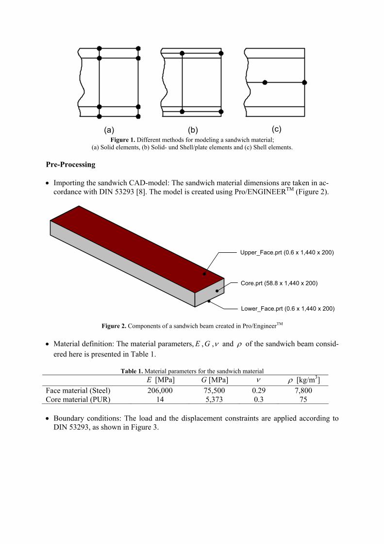
(a) (b) (c) Figure 1. Different methods for modeling a sandwich material;
(a) Solid elements, (b) Solid- und Shell/plate elements and (c) Shell elements. Pre-Processing • Importing the sandwich CAD-model: The sandwich material dimensions are taken in ac-
cordance with DIN 53293 [8]. The model is created using Pro/ENGINEERTM (Figure 2).
Upper_Face.prt (0.6 x 1,440 x 200)
Core.prt (58.8 x 1,440 x 200)
Lower_Face.prt (0.6 x 1,440 x 200)
Figure 2. Components of a sandwich beam created in Pro/EngineerTM • Material definition: The material parameters, E ,G ,ν and ρ of the sandwich beam consid-
ered here is presented in Table 1.
Table 1. Material parameters for the sandwich material E [MPa] G [MPa] ν ρ [kg/m3] Face material (Steel) 206,000 75,500 0.29 7,800 Core material (PUR) 14 5,373 0.3 75 • Boundary conditions: The load and the displacement constraints are applied according to
DIN 53293, as shown in Figure 3.

1200
F/2
60
600300
1440
F/2
Y
XZ
Unit: mm
VR2VR1
Figure 3. Boundary conditions
Modeling in ANSYSTM Two different methods to model sandwich materials using ANSYSTM are presented here: • Method I: Using solid elements This method uses three solid parts to create a sandwich element. All parts are glued together and the nodes at the face-core interface are shared together. Here, the solid element of ANSYSTM (SOLID45) has been employed for modeling the faces and the core. SOLID45 is commonly used for 3-D modeling of solid structures. Figure 4 shows this element, which is defined by eight nodes having three degree of freedom at each node: translations in the nodal x, y and z directions.
PO
K
N
J
I
M
L
6
2
3
1
4
5
Y
Z
X
x
y
z
Surface Coordinate System
Figure 4. SOLID45-Element
The VGLUE command (ANSYSTM) is used to generate a new volume of the sandwich mate-rial by “gluing” all the three solid parts. This operation is only valid if the interfaces are co-planar. Thereafter, the volumes are meshed with appropriate element sizes. By using the nodal merging command NUMMRG, NODE (ANSYSTM), two coincident nodes are replaced by a single node (Figure 5).

2924302229752180
2925302129742181
2926302029732182 Face
Core
Figure 5. Method I: Common nodes • Method II: Using solid and shell elements In this method, the solid element (SOLID45) and the shell element of ANSYSTM (SHELL181) are used for modeling the core and the faces respectively. SHELL181 can also be used for layered applications; in modeling laminated composite shells or sandwich con-struction. Modeling sandwich faces with SHELL18 has first order accuracy, whose deforma-tions are governed by shear deformation theory (usually referred to as Mindlin-Reissner plate theory). SHELL181 is a 4-node element with six degrees of freedom at each node: transla-tions in the x, y, and z directions, and rotations about the x, y, and z-axes (Figure 6).
P
K
J
I
L
2
4
1
2
6
Y
Z
X
xy yo
xo
zo
z
1
5
2
6
3
7
4
8
5
x
Figure 6. SHELL181 Element The advantage of this method over ANSYS Method I is that there is no need to create the ge-ometry of sandwich face-plate neither in CAD-Software nor in pre-processor of ANSYSTM. The Partition tool of ANSYSTM can be used to divide surfaces of solid into face materials (Figure 7). Then, the cross-sectional area of the face material can be defined. Figure 8 shows the representation of the sandwich model after meshing; the nodes of faces and core are shared together.

Partition areas
Figure 7. Partition
562 564 567565563 Face
Core
Figure 8. Method II: Common nodes Modeling in ALGORTM This method also uses three solid parts to define sandwich geometry. By using the “midplane-element” option, a solid model can be converted easily in to a plate element. Thickness of the plate is calculated automatically from the geometry data (Figure 9). This option makes ALGORTM more user-friendly than ANSYSTM.
Thickness
Y
X
Z
Figure 9. Generation of a midplane plate element The sandwich model is created using the solid element (BRICK) and the plate elements (PLATE) of ALGORTM. Contact pair shall be defined between the face sheet and the core. The contact type "Bonded"(ALGORTM) is used for this model. After meshing, the bonded surfaces are in perfect contact with each other throughout the analysis.

Modeling in ABAQUS/StandardTM
The sandwich model can be created using a continuum element (C3D20) and shell elements (S4) of ABAQUS/StandardTM. This element S4 is based on first-order transverse shear flexi-ble theory in which the transverse shear strain is assumed to be constant through the thickness of the shell.
ABAQUS/StandardTM has a special feature called “skin reinforcement” to create a sandwich material. Skin reinforcement defines a skin that is bonded to the surface of a solid part (Fig-ure 10). Before meshing, different elements can be assigned to the skin and the solid parts. In this case, C3D20 is assigned to the core and S4 is assigned to the skin material (face). Both elements share common nodes.
Upper skin reinforcement
Core
Lower skin reinforcement Figure 10. Skin reinforcement
EXPERIMENTAL SETUP
Test Specimen and Specifications The four-point bending test is performed in accordance with DIN 53293 (Figure 11). The di-mensions of sandwich beam are presented in Table 2.
Table 2. Beam dimensions Parameters H L LA LB LS b tf c D
Dimensionen [mm] 60 1,440 1,200 300 600 200 0.6 58.8 59.4

LA = 20h
F
≈h
h
LS = 10hLB = 5h
L = 24h
Ec,Gc
tf
tf
d
Ef
Ef
c2
chd +=
b
Y
XZ
Figure 11. Specifications according to DIN 53293. The test specimens have been fabricated from steel facings and PUR foam core (Figure 13). The material properties of this sandwich material are provided in Table 1. The steel facings are bonded to the PUR foam core with an epoxy adhesive.
Figure 12. Test specimen Testing Equipment and Experimental Procedure The sandwich beam specimens were tested with 33 kN hydraulic press controlled by DYNA-MESSTM controller. Quasi-static tests have been performed to get relevant load and displace-ment levels for the four-point bending tests. Each specimen has been placed in the testing fix-ture as show in Figure13. The cylindrical loading and support rollers are placed in such a way that the effective beam span (distance between support rollers) is 1,200 mm, and the loading span (distance between cylindrical loading rollers) is 600 mm. A linear varying displacement
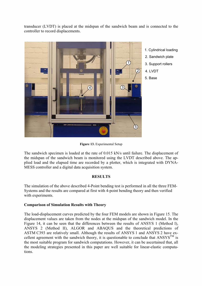
transducer (LVDT) is placed at the midspan of the sandwich beam and is connected to the controller to record displacements.
1
2
34
5
1. Cylindrical loading
2. Sandwich plate
3. Support rollers
4. LVDT
5. Base
Figure 13. Experimental Setup The sandwich specimen is loaded at the rate of 0.015 kN/s until failure. The displacement of the midspan of the sandwich beam is monitored using the LVDT described above. The ap-plied load and the elapsed time are recorded by a plotter, which is integrated with DYNA-MESS controller and a digital data acquisition system.
RESULTS The simulation of the above described 4-Point bending test is performed in all the three FEM-Systems and the results are compared at first with 4-point bending theory and then verified with experiments. Comparison of Simulation Results with Theory The load-displacement curves predicted by the four FEM models are shown in Figure 15. The displacement values are taken from the nodes at the midspan of the sandwich model. In the Figure 14, it can be seen that the differences between the results of ANSYS 1 (Method I), ANSYS 2 (Method II), ALGOR and ABAQUS and the theoretical predictions of ASTM C393 are relatively small. Although the results of ANSYS 1 and ANSYS 2 have ex-cellent agreement with the sandwich theory, it is questionable to conclude that ANSYSTM is the most suitable program for sandwich computations. However, it can be ascertained that, all the modeling strategies presented in this paper are well suitable for linear-elastic computa-tions.

Figure 14. Midspan force-deplacement curves of four-point bending simulation
Qualitative Evaluation of the Applied FEM-Programs The purpose of this evaluation is to provide design engineers, working with sandwich struc-tures to select an appropriate FEM-Software. An objective evaluation of the considered FEM-Softwares is difficult; it depends on the application of the simulation and the evaluation crite-ria to be considered. Therefore in this section, only a qualitative evaluation of applied FEM-Softwares with respect to sandwich structures is performed. The evaluation of the commercial FEM-Systems was carried out by using the Use-Value Analysis (UVA) [1]. There are 22 cri-teria considered for this evaluation and the interested reader is referred to Torsakul [11]. These criteria are classified in 3 major criteria and their corresponding weightage in the evaluation are given in brackets:
• Creation of FE Model (60%)
• Computation (10%)
• Post-processing of results (30%)
Grades are given to all the 22 criteria ranging from 0.0 to 4.0, with an increasing step of 1.0. Grade 4.0 and grade 0.0 indicates the excellent fulfilment and the worst fulfilment of the con-sidered evaluation criteria respectively. In Figure 15, the cumulative grade point average of the considered FEM-Softwares is presented.

Figure 15. The Evaluation of FEM-Softwares
ALGORTM has a leading edge in pre-processing over other softwares because of its ease of use. For example, with the help of “Midplane option”, thin walled structures from CAD-Geometry can be easily converted in to plate elements. Also the post-processor contributes intuitive operability and fairly agreeable documentation of the results. On contrary, ALGORTM has less element option in comparison with ANSYSTM, which constrains the mod-eling possibilities. ANSYSTM obtains overall good results and could be favored, if the indi-vidual user is trained to use it as an efficient system. For the group of engineers, who does not have much experience in finite element technology for modeling sandwich materials, ALGORTM has clear advantages. ABAQUSTM has an extensive library for material modeling with excellent documentation, but the pre- and post-processing options are relatively compli-cated in comparison with ALGORTM and ANSYSTM. Comparison of FEM with Experimental Results Comparison of the results of simulation and experiment shows that the deflection behavior of considered sandwich beam has excellent agreement with the simulation results of ANSYS 1 in the linear-elastic region (Figure 16). Thus, the linear-elastic material model is permissible for the range of small loads of 0-1.500 N. In addition, the experiment shows that the sandwich beam behaves increasingly flexible above this limit.
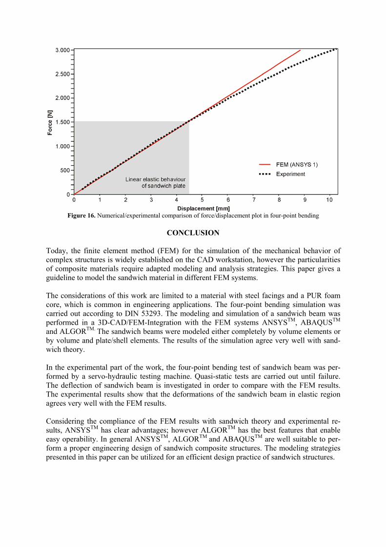
Figure 16. Numerical/experimental comparison of force/displacement plot in four-point bending
CONCLUSION
Today, the finite element method (FEM) for the simulation of the mechanical behavior of complex structures is widely established on the CAD workstation, however the particularities of composite materials require adapted modeling and analysis strategies. This paper gives a guideline to model the sandwich material in different FEM systems. The considerations of this work are limited to a material with steel facings and a PUR foam core, which is common in engineering applications. The four-point bending simulation was carried out according to DIN 53293. The modeling and simulation of a sandwich beam was performed in a 3D-CAD/FEM-Integration with the FEM systems ANSYSTM, ABAQUSTM and ALGORTM. The sandwich beams were modeled either completely by volume elements or by volume and plate/shell elements. The results of the simulation agree very well with sand-wich theory. In the experimental part of the work, the four-point bending test of sandwich beam was per-formed by a servo-hydraulic testing machine. Quasi-static tests are carried out until failure. The deflection of sandwich beam is investigated in order to compare with the FEM results. The experimental results show that the deformations of the sandwich beam in elastic region agrees very well with the FEM results. Considering the compliance of the FEM results with sandwich theory and experimental re-sults, ANSYSTM has clear advantages; however ALGORTM has the best features that enable easy operability. In general ANSYSTM, ALGORTM and ABAQUSTM are well suitable to per-form a proper engineering design of sandwich composite structures. The modeling strategies presented in this paper can be utilized for an efficient design practice of sandwich structures.

ACKNOWLEDGEMENTS
This research has been supported by Chair and Institute for Engineering Design (IKT), Aachen University of Technology, Germany. Furthermore, special thanks to the Hybrid Struc-ture team and workshop team of IKT for their kind co-operation.
REFERENCES
1. Pahl, G., Beitz, W., Feldhusen, J. and Grote, K.H. (2005). Konstruktionslehr-Grundlagen erfolgreicher Produktenwicklung, Methoden und Anwendung, 6 Auflage, Heidelberg, Germany.
2. Allen, H.G. (1969). Analysis and Design of Structural Sandwich Panels, Pergamon: Press, Ltd, London, UK.
3. Bull, P. (2004). Damage Tolerance and Residual Strength of Composite Sandwich Struc-tures, KTH Aeronautical and Vehicle Engineering, Stockkholm, Sweden.
4. Pflung, J., Vagrimde, B. and Verpoest, I. (2002). Material efficiency and cost effectiveness of Sandwich Materials, Katholieke University, Leuven, Belgium.
5. Burman, M. (1998). Fatigue Crack Initiation and Propagation in Sandwich Structures, Division of Lightweight Structures, Royal Institute of Technology, Stockholm, Sweden.
6. Zenkert, D. (1997). The Handbook of Sandwich Construction, Engineering Materials, Advisory Service, Ltd, West Midlands, UK.
7. ASTM C393. (2000). Standard Test Method for Flexural Properties of Sandwich Con-structions, Annual Book of ASTM Standards, Vol. 15.03.
8. DIN 53293. (1982). Prüfung von Kernverbunden: Biegeversuch, Deutsche Institut für Normung e.V.
9. Torsakul, S. (2007). Modellierung und Simulation eines Verbunds von Sandwichplatten zur Entwicklung einer mechanischen Verbindungstechnik, Doctoral thesis, RWTH Aachen.