feis vol 2 2012-10 - town of wappinger vol 2_06 appendix 11.pdf · 6 system analysis ... is a 225...
TRANSCRIPT

Hilltop Village at Wappinger Active Adult Community Final Environmental Impact Statement
R:\pe-mydoc\0500\0552\EIS\FEIS\FEIS Vol 2_2012-10.docx
Appendix 11
Water Supply System Engineering Report

Hilltop Village at Wappinger All Angels Hill Road, Town of Wappinger, NY
Table of Contents
i R:\pe-mydoc\0500\0552\Reports\Water\2012-0827_FEIS\0552 PW 2012-0827(cmz).docx
1 Introduction ............................................................................................... 1
2 Water Supply .............................................................................................. 1
3 Design Flow ............................................................................................... 1
4 Fire Suppression ........................................................................................ 2
5 Proposed Water Distribution System ........................................................ 3 5.1 Connections ........................................................................................................ 3 5.2 Distribution ........................................................................................................ 3 5.3 Service Connections ........................................................................................... 4
6 System Analysis ......................................................................................... 4 6.1 Distribution ........................................................................................................ 4 6.2 Service Connections ........................................................................................... 5
7 Existing Well Abandonment ..................................................................... 6
8 Completion ................................................................................................ 7 Tables Table 1: Anticipated Domestic Water Demand ............................................................................................ 1 Table 2: ISO Needed Fire Flow for Residential Dwellings ......................................................................... 2 Figures 1 USGS Site Location Map 2 Cider Mill Loop Road Existing Water Storage Tank Location 3 Stone Lined Well Appendices A Town Correspondence B Design Calculations C Testing & Disinfection Standards

Hilltop Village at Wappinger All Angels Hill Road, Town of Wappinger, NY
1 R:\pe-mydoc\0500\0552\Reports\Water\2012-0827_FEIS\0552 PW 2012-0827(cmz).docx
1 Introduction
The Applicant, Toll Brothers, Inc., is proposing to develop a 145.30 acres of a 149.35 acre parcel located at All Angels Hill Road (CR 94) in the Town of Wappinger, New York (see Figure 1). The proposed project, “Hilltop Village at Wappinger”, is a 225 unit age restricted residential development that consists of 132 single family homes, 93 townhomes, and a clubhouse with recreational facilities (e.g., swimming pool and tennis court). The site is identified on the Town of Wappinger Tax Map as Tax Number 6257-02-630770.
2 Water Supply
The project is located in the Central Wappinger Water Improvement Area #1 (CWWIA) of the United Wappinger Water District (UWWD). Water supply for this project has been allocated by the Town of Wappinger under/as part of Water Improvement Project 99-2(R).
3 Design Flow
The design flow for the water distribution system is based on design flow rates as published in the New York State Department of Environmental Conservation (NYSDEC) Design Standards for Wastewater Treatment Works, 1988. However, the Town of Wappinger has specific average daily flow rates for the single family homes and the townhomes, which will be used in lieu of the NYSDEC unit flow rates. The anticipated water demand from each of the uses on the site is summarized in Table 1 below.
Table 1: Anticipated Domestic Water Demand
Use Type Size Unit Flow Rate per
Unit (gpd) Water Demand
(gpd)
Single Family Homes 132 homes 320(1) 42,240 Townhomes 93 homes 200(2) 18,600 Clubhouse (2-story) 7,330 Sq. ft. 0.08(3) 586 Swimming Pool (1,071 sf) 71(4) swimmers 10(5) 710
Total 62,136 (1) The average daily use for a single family home with no more than four-bedrooms per residential unit in
accordance with the Town of Wappinger’s practices (Chapter 236-6 of the Town Code). (2) The average daily use for a two-bedroom apartment/unit in accordance with the Town of Wappinger’s
practices (Chapter 236-6 of the Town Code). (3) Water saving plumbing fixtures will be used and the NYSDEC Design Standards for Wastewater Treatment
Works permits a 20 percent reduction in the hydraulic loading rate. The values shown have already been reduced by 20 percent.
(4) Number of swimmers/bathers is estimated on the basis of 15 sf of pool water surface area per patron as recommended in NYS Sanitary Code Subpart 6-1.
(5) NYSDEC Design Standards for Wastewater Treatment Works hydraulic loading rate without water saving plumbing fixture reduction.

Hilltop Village at Wappinger All Angels Hill Road, Town of Wappinger, NY
2 R:\pe-mydoc\0500\0552\Reports\Water\2012-0827_FEIS\0552 PW 2012-0827(cmz).docx
4 Fire Suppression
The residential development is located in the Town of Wappinger New Hackensack Fire District. The Insurance Services Office (ISO) Guide for Determination of Needed Fire Flow, effective edition, was used to determine the fire flow requirements for the proposed buildings. The needed fire flows for one- and multi-family dwellings no exceeding two stories in height is summarized in Table 2 below.
Table 2: ISO Needed Fire Flow for Residential Dwellings Distance Between
Buildings Needed Fire Flow
(gpm)
More than 100’ 500 31-100’ 750 11-30’ 1,000
10’ or less 1,500 Using Table 2 and the various separation distances between the buildings, needed fire flow ranges were determined for the single family homes and townhomes. The distance between the single family homes ranges from 15 to 35 feet. Therefore, the needed fire flow ranges from 750 to 1,000 gpm. The distance between the townhomes ranges from 15 to 35 feet. Therefore, the needed fire flow ranges from 750 to 1,000 gpm. For design purposes, the required fire flow is: Single Family Homes = 1,000 gpm. Townhomes = 1,000 gpm. The needed fire flow for the clubhouse was determined by using the Needed Fire Flow (NFFi) formula:
NFFi=(Ci)(Oi)(1.0+(Xi+Pi)) Where:
Ci = construction factor, where C=18(F)(Ai)0.5
F = construction class Ai = effective area Oi = occupancy factor Xi = exposure factor Pi = factor for communication between buildings
Therefore, the needed fire flow for the clubhouse was determined to be:
Ai = 3,665 sf + ½ x 3,665 sf = 5,498 sf Ci = 1,250 (from Appendix A of ISO using a F of 1.0) NFFi = 1,250 x 0.85 x (1.0+(0+0)) = 1,063 gpm
Rounded to the nearest 250 gpm, the needed fire flow for the clubhouse is 1,000 gpm.

Hilltop Village at Wappinger All Angels Hill Road, Town of Wappinger, NY
3 R:\pe-mydoc\0500\0552\Reports\Water\2012-0827_FEIS\0552 PW 2012-0827(cmz).docx
Based upon a discussion with Chief Rick Anderson, the New Hackensack Fire District owns the following pieces of Fire Apparatus:
Three Class A Pumpers which all have 1,500 gpm pumps and 1,000 gallons water tanks. One Water Tankers with 2,000 gallons of water and 350 gpm pumps on each. One Heavy Duty Rescue Truck. Two Utility Trucks with a 150 gallon water tank and a 150 psi pump. Three four-wheel drive trucks.
According to Chief Anderson, the New Hackensack Fire District would have no difficulty providing fire protection to the proposed development.
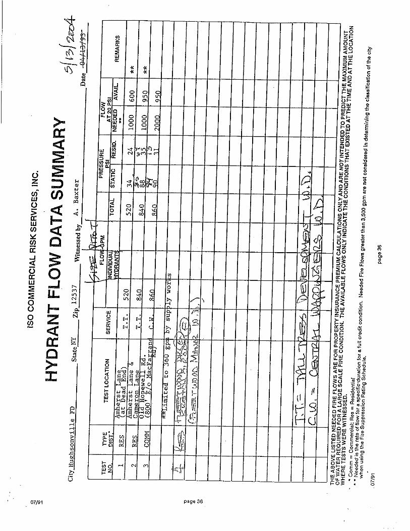
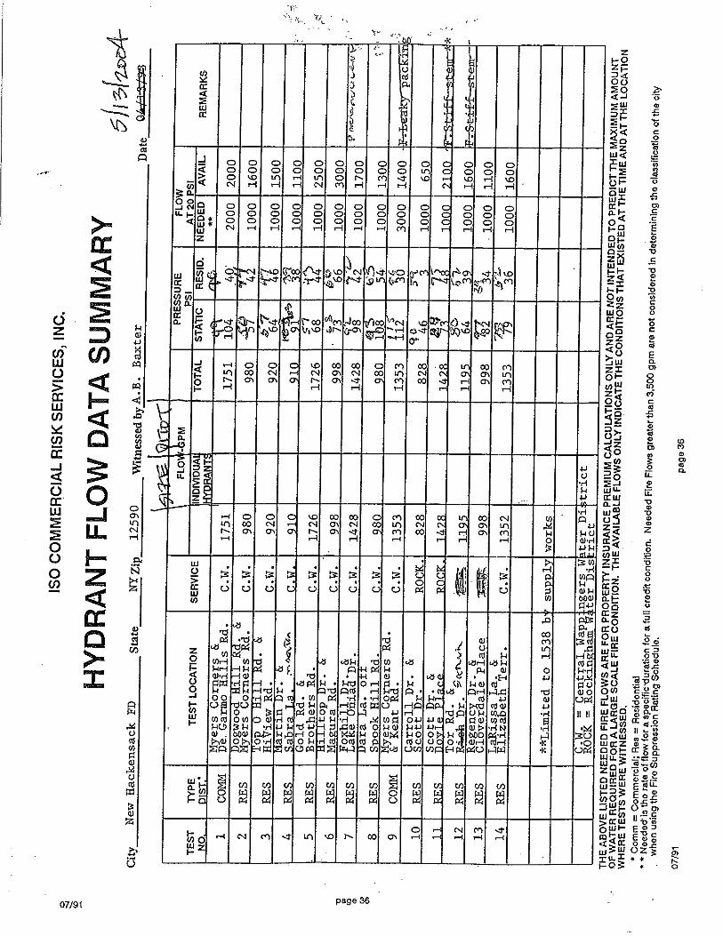
According to the Town Water System Operator (CAMO Pollution Control, Inc.), the hydrant pressure at Rich Drive is between 80-83 psi (see Appendix A). The Town Water System Operator provided hydrant test flow data for hydrants within the vicinity of the Proposed Action; however, no flow data is available for the hydrant located at the end of Rich Drive (see Appendix A). Flow data was available for a hydrant located at Tor Road and Sarah Drive, which is located approximately 745 feet from the proposed connection point at an approximate elevation of 282. The recorded flow was 1,195 gpm with a static pressure of 80 psi and a residual pressure of 52 psi. This hydrant is comparable in elevation and static pressure to that observed at the hydrant on Rich Drive hydrant and should provide similar flow rates in excess of 1,000 gpm. The needed fire flow for the development is 1,000 gpm; therefore, the water system can adequately produce the required fire flow for the proposed development.
5 Proposed Water Distribution System
5.1 Connections
The project will connect to the existing Town water system at two (2) locations – Shamrock Hills Drive to the west and Rich Drive to the east. The proposed water distribution system will be designed to serve all of the residential homes and clubhouse. Water service from the main to each of the residential homes and clubhouse will be provided through individual service line connections. 5.2 Distribution
The proposed water distribution system will be designed to serve all of the residential homes and clubhouse. The water main will be an 8-inch Class 52, cement-lined ductile iron pipe complying with the American Water Works Association (AWWA) Standards C151 and C104. The water main will generally be in or along roadways or parking areas. A ten foot horizontal separation distance and an 18-inch vertical separation distance will be provided between sanitary sewer and stormwater lines. All water distribution and service lines will be installed at a minimum of five feet below finished grade to provide for frost protection.

Hilltop Village at Wappinger All Angels Hill Road, Town of Wappinger, NY
4 R:\pe-mydoc\0500\0552\Reports\Water\2012-0827_FEIS\0552 PW 2012-0827(cmz).docx
Isolation valves will be placed at not more than 800-foot intervals along the water mains. Hydrants will be placed at each street intersection and at intermediate points along the water main generally spaced between 350 and 600-feet. 5.3 Service Connections
Water service from the main to each of the single family homes, townhomes, and clubhouse building will be provided through individual service lines. The service lines for the single family homes and townhomes will be ¾ to 1 inch Type K copper with a corporation stop at the main and a curb stop near the pavement line. The water service and fire suppression lines for the clubhouse will be a 1-½ inch Type K copper and 6-inch Class 52 cement-lined ductile iron pipe, respectively, with valves placed near the pavement line.
6 System Analysis
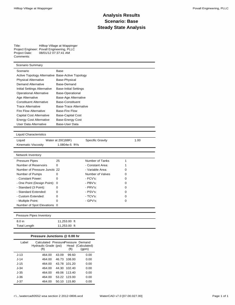
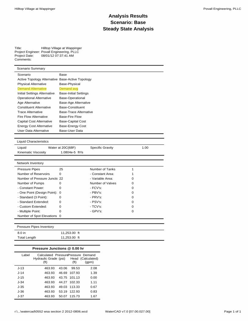
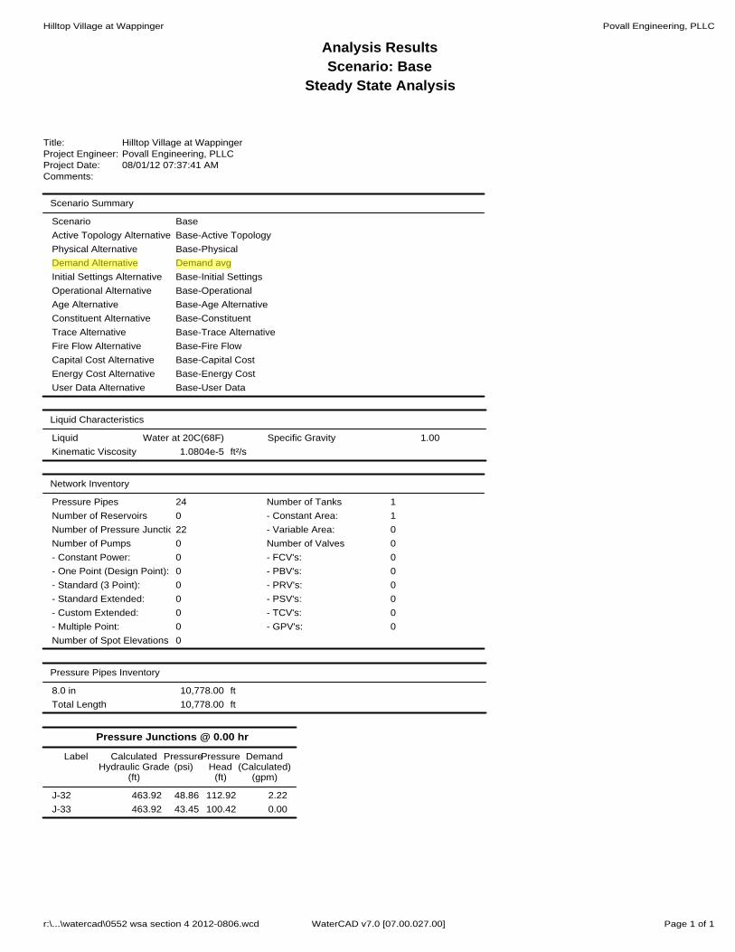
The proposed water distribution system “floats” off of the storage tank located off of Cider Mill Loop Road (see Figure 2) in the western portion of the Town of Wappinger. According to the “Engineer’s Report Water Supply System Shamrock Hills Subdivision” prepared by Povall Engineering, PLLC last revised February 22, 2006 and approved by the DCDOH on August 16, 2006, the atmospheric tank is located at an isolated high point with an overflow elevation of approximately 470 and a normal minimum working elevation of 464 as reported by the Town Engineer and Town Water System Operator. The tank is located approximately 4,750 feet from the proposed Rich Drive connection and approximately 12,050 feet from the tee connection in the ROW off of Shamrock Hills Drive. 6.1 Distribution
According to the Town of Wappinger Water System Operator, the hydrant pressure at Rich Drive is between 80-83 psi; and at 111 Shamrock Hills Drive (easement between Shamrock Hills Drive and Maxwell Place) is 46-48 psi (see Appendix A). Static Pressure The water distribution system supplying the project was analyzed to verify that proper pressure conditions will be provided. WaterCAD was used to determine the pressures throughout the system at various locations, such as at intersections and hydrants. The static pressure at the tested hydrant at the end of Rich Drive is calculated as follows:
The highest static pressure will occur when the water elevation within the storage tank is at the overflow:
Hydrant Elev. = 280± Atmospheric or 0 psi = water elevation at 470 at the tank overflow
hs = hb – ha = 470 – 280 = 190 ft elevation change Pstatic = 190 ft x 62.4 lb/ft3 x (1 sf/144 in2) = 82 psi.
Hilltop Village at Wappinger All Angels Hill Road, Town of Wappinger, NY
5 R:\pe-mydoc\0500\0552\Reports\Water\2012-0827_FEIS\0552 PW 2012-0827(cmz).docx
The normal lowest static pressure will occur when the water elevation within the storage tank is at the normal minimum working level:
Hydrant Elev. = 280± Atmospheric or 0 psi = water elevation at 464 at the normal minimum working level
hs = hb – ha = 464 – 280 = 184 ft elevation change Pstatic = 184 ft x 62.4 lb/ft3 x (1 sf/144 in2) = 80 psi.
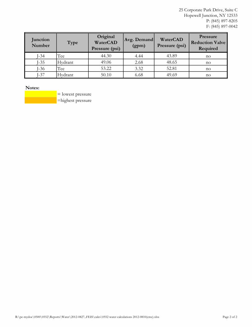
The static pressure at the connection point to the water main on Rich Drive as determined by the analysis is ±80 psi. The minimum recommended normal working pressure is 35 psi as per Ten States Standards for Water Works, 2012. The normal working pressure throughout the water system ranges from 39 to 80 psi. The anticipated minimum static pressure within the proposed development complies with the minimum recommended normal working pressure. The calculated static pressure at various points throughout the system is provided in Appendix B. Static Pressure during Average Demand Conditions The lowest working pressure of 39 psi occurred at the hydrant near townhome T53 during average demand conditions. The highest working pressure of 80 psi occurred at the proposed connection point on Rich Drive during average demand conditions. The anticipated minimum static pressure with average demand conditions within the proposed development complies with the minimum recommended normal working pressure of 35 psi. The analysis and comparison are provided in Appendix B. Static Pressure during Peak Demand Conditions The lowest working pressure of 39 psi occurred at the hydrant near townhome T53 during peak demand conditions. The highest working pressure of 80 psi occurred at the proposed connection point on Rich Drive during peak demand conditions. The anticipated minimum static pressure with peak demand conditions within the proposed development complies with the minimum recommended normal working pressure of 35 psi. The analysis and comparison are provided in Appendix B. Static Pressure during Fire Flow Conditions The lowest normal working pressure of 35 psi occurred at the hydrant near townhome T53 during fire flow conditions. The highest normal working pressure of 76 psi occurred at the proposed connection point on Rich Drive during fire flow conditions. The anticipated minimum static pressure with fire flow conditions within the proposed development complies with the minimum recommended normal working pressure of 35 psi. The analysis and comparison are provided in Appendix B. 6.2 Service Connections
Given the existing configuration of the water distribution system which includes many areas with looped distribution and the fact that the proposed system will also be looped and will connect to looped water systems on Rich Drive and Shamrock Hills Drive, pressure losses due to friction (flow

Hilltop Village at Wappinger All Angels Hill Road, Town of Wappinger, NY
6 R:\pe-mydoc\0500\0552\Reports\Water\2012-0827_FEIS\0552 PW 2012-0827(cmz).docx
conditions) are assumed to be minimal and not significant. This conclusion is also supported as can be seen above; the static pressures calculated at the end of Rich Drive are consistent with the pressures that were recorded at this location under normal flow operating conditions. Therefore, the system pressures were analyzed for static condition. The static condition pressures are as follows:
The highest static pressure will occur at the lowest proposed home S107 with the water elevation within the storage tanks at the overflow:
S107 FFE = 315.1 Atmospheric or 0 psi = water elevation at 470 at the tank overflow
hs = hb – ha = 470 – 315.1 = 155 ft elevation change Pstatic = 155 ft x 62.4 lb/ft3 x (1 sf/144 in2) = 67 psi.
The normal lowest static pressure will occur at the proposed townhomes T51 and T52 with the water elevation within the storage tank at the normal minimum working level:
T51 and T52 FFE = 383.2 Atmospheric or 0 psi = water elevation at 464 at the normal minimum working level
hs = hb – ha = 464 – 383.2 = 81 ft elevation change Pstatic = 81 ft x 62.4 lb/ft3 x (1 sf/144 in2) = 35 psi.
The minimum recommended working pressure is 35 psi as per Ten States Standards for Water Works, 2012. The normal working pressure ranges from 35 to 67 psi. The anticipated minimum static pressure within the proposed development complies with the minimum recommended working pressure. Although typical plumbing and appurtenances are capable of accommodating 100 psi pressures, individual pressure reduction valves will be specified for all homes where pressure at the meter will be in excess of 80 psi. The calculated static pressure for each of the units is provided in Appendix B.
7 Existing Well Abandonment
An existing well was located approximately 179 feet east of the existing sanitary sewer line running parallel to All Angels Hill Road during the Phase 1B Archeological Investigation (see Figure 3). The existing well shall be abandoned prior to the commencement of construction. A permit shall be obtained from the Dutchess County Department of Health prior to abandonment. If the well is very deep and narrow, it shall be sealed it with either bentonite or concrete. If the well is shallow and wide, it shall be backfilled. The well abandonment shall be certified in writing to the DCDOH by a NYS licensed professional engineer.
Hilltop Village at Wappinger All Angels Hill Road, Town of Wappinger, NY
7 R:\pe-mydoc\0500\0552\Reports\Water\2012-0827_FEIS\0552 PW 2012-0827(cmz).docx
8 Completion
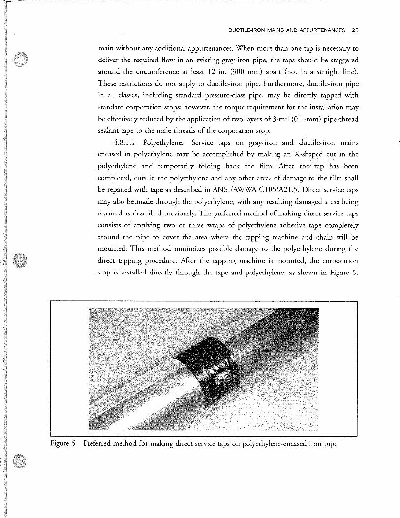
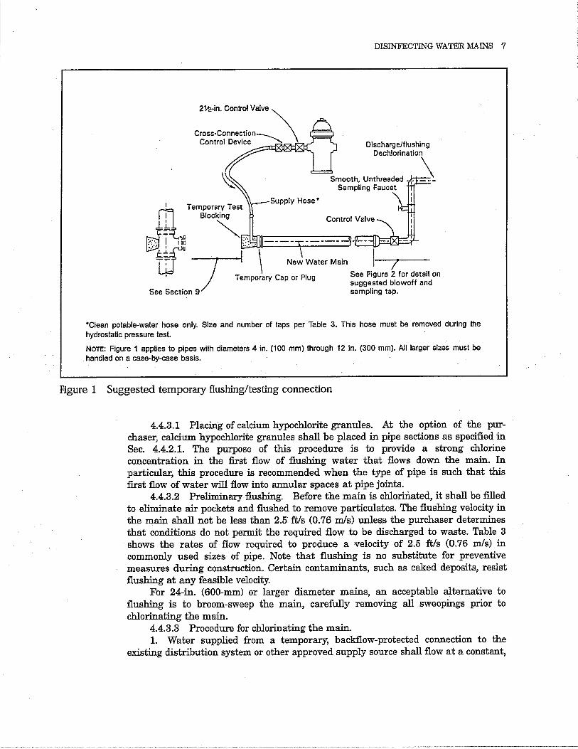
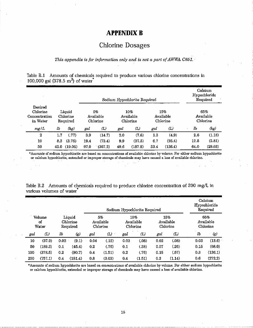
This report is an integral part of the project plans. All construction shall conform to the project plans. All construction shall conform to the project plans and the latest AWWA standards. The completed work shall be inspected by a New York State licensed professional engineer. All parts of the system shall be pressure tested in accordance with AWWA Standard C600 and disinfected with a chlorine solution in accordance with AWWA Standard C651. The tablet method of disinfection shall not be used. All completed construction and testing shall be certified in writing to the DCDOH and Town by a New York State licensed professional engineer prior to being placed in service. The testing and disinfection standards have been provided in Appendix C for reference purposes.

Hilltop Village at Wappinger All Angels Hill Road, Town of Wappinger, NY
R:\pe-mydoc\0500\0552\Reports\Water\2012-0827_FEIS\0552 PW 2012-0827(cmz).docx
Figures

SITE
WAPPINGERS FALLS AND HOPEWELL JUNCTION QUADRANGLES
SCALE:
DATE:
JOB #:WILLIAM H. POVALL III, P.E.N.Y.S.P.E. LICENSE #075020
25 CORPORATE PARK DR., SUITE CHOPEWELL JUNCTION, NY 12533
TEL.: (845) 897-8205FAX: (845) 897-0042
File Path: R:\PE\DRAWINGS\0500\0552\dwg\0552_SWA 2011-09.dwg, Layout: FIG 1 USGS
HILLTOP VILLAGE AT WAPPINGER
USGS SITE LOCATION MAP
TOWN OF WAPPINGER DUTCHESS COUNTY, NEW YORK
0552
06/27/11
1"=2000'
FIGURE 1

SCALE:
DATE:
JOB #:WILLIAM H. POVALL III, P.E.N.Y.S.P.E. LICENSE #075020
25 CORPORATE PARK DR., SUITE CHOPEWELL JUNCTION, NY 12533
TEL.: (845) 897-8205FAX: (845) 897-0042
HILLTOP VILLAGE AT WAPPINGER
CIDER MILL LOOP ROAD
TOWN OF WAPPINGER DUTCHESS COUNTY, NEW YORK
0552
08/03/11
1"=600'
FIGURE 2
LEGEND
EXISTING WATER STORAGE TANKS

SCALE:
DATE:
JOB #:WILLIAM H. POVALL III, P.E.N.Y.S.P.E. LICENSE #075020
25 CORPORATE PARK DR., SUITE CHOPEWELL JUNCTION, NY 12533
TEL.: (845) 897-8205FAX: (845) 897-0042
HILLTOP VILLAGE AT WAPPINGER
STONE LINED WELLTOWN OF WAPPINGER DUTCHESS COUNTY, NEW YORK
0552
08/03/11
1"=80'
FIGURE 3

Hilltop Village at Wappinger All Angels Hill Road, Town of Wappinger, NY
R:\pe-mydoc\0500\0552\Reports\Water\2012-0827_FEIS\0552 PW 2012-0827(cmz).docx
Appendix A
Town Correspondence


1
Christina Zolezi
From: Michael P. Tremper [[email protected]]Sent: Tuesday, December 20, 2011 3:53 PMTo: [email protected]: [email protected]: Hilltop Village at Wappinger Water & Sewer Info. RequestAttachments: Kendall_Farms_Shamrock_Pump_Hours.rtf
Follow Up Flag: Follow upFlag Status: Flagged
Ms. Zolezi: Per your request, CAMO Pollution Control, Inc. provides the following: 1) For "as-built" maps, I would request that you come to our office to review existing "as-builts", and we will have Morris Associates copy what you need. 2) There are no flow meters on either the Shamrock or Kendall Farms pump stations. However, we do track pump hours which are attached. 3) Rich Drive hydrant static pressure - 80 lb.s 111 Shamrock Hills Drive hydrant static pressure - 48 lbs. 4) Our water system works off of gravity from the Cider Mill Loop storage tanks, which are usually full. You can determine the pressure at any point, based on that elevation. Thank you, and Merry Christmas. Mike Tremper CAMO Pollution Control, Inc.

Hilltop Village at Wappinger All Angels Hill Road, Town of Wappinger, NY
R:\pe-mydoc\0500\0552\Reports\Water\2012-0827_FEIS\0552 PW 2012-0827(cmz).docx
Appendix B
Design Calculations

25 Corporate Park Drive, Suite CHopewell Junction, NY 12533
P: (845) 897-8205F: (845) 897-0042
Job Name: Hilltop Village at Wappinger Job No.: 0552Prepared By: CMZ Revised By: CMZDate: Rev. Date: 8/10/12Reviewed By: WHP Reviewed By: WHP
Water elevation within water storage tanks at:Overflow = 470 ftNormal minimum working level = 464 ft
Normal working pressure range = approx. 60 to 80 psiRequired minimum normal working pressure = 35 psi
UnitFinshed Floor Elevation (ft)
Pressure @ Normal Min. Working (psi)
Pressure @ Overflow (psi)
Pressure Reduction Valve
Required
Club House 340.0 53.7 56.3 noS1 360.7 44.8 47.4 noS2 364.2 43.2 45.8 noS3 367.7 41.7 44.3 noS4 371.2 40.2 42.8 noS5 374.7 38.7 41.3 noS6 376.2 38.0 40.6 noS7 373.9 39.0 41.6 noS8 371.4 40.1 42.7 noS9 368 3 41 5 44 1
HOME PRESSURE CALCULATIONS
9/21/11
S9 368.3 41.5 44.1 noS10 364.6 43.1 45.7 noS11 360.7 44.8 47.4 noS12 357.2 46.3 48.9 noS13 355.6 47.0 49.6 noS14 356.2 46.7 49.3 noS15 357.9 46.0 48.6 noS16 361.8 44.3 46.9 noS17 365.3 42.8 45.4 noS18 368.8 41.3 43.9 noS19 371.4 40.1 42.7 noS20 371.8 40.0 42.6 noS21 371.0 40.3 42.9 noS22 369.0 41.2 43.8 noS23 366.3 42.3 44.9 noS24 363.6 43.5 46.1 noS25 360.8 44.7 47.3 noS26 358.1 45.9 48.5 noS27 355.3 47.1 49.7 noS28 352.5 48.3 50.9 no
R:\pe-mydoc\0500\0552\Reports\Water\2012-0827_FEIS\calcs\0552 water calculations 2012-0810(cmz).xlsx Page 1 of 6

25 Corporate Park Drive, Suite CHopewell Junction, NY 12533
P: (845) 897-8205F: (845) 897-0042
UnitFinshed Floor Elevation (ft)
Pressure @ Normal Min. Working (psi)
Pressure @ Overflow (psi)
Pressure Reduction Valve
Required
S29 350.1 49.4 52.0 noS30 371.8 40.0 42.6 noS31 370.8 40.4 43.0 noS32 369.1 41.1 43.7 noS33 367.2 41.9 44.5 noS34 365.3 42.8 45.4 noS35 356.5 46.6 49.2 noS36 355.7 46.9 49.5 noS37 356.4 46.6 49.2 noS38 357.7 46.1 48.7 noS39 359.9 45.1 47.7 noS40 362.0 44.2 46.8 noS41 368.4 41.4 44.0 noS42 370.5 40.5 43.1 noS43 373.3 39.3 41.9 noS44 375.5 38.4 41.0 noS45 378.2 37.2 39.8 noS46 379.9 36.4 39.0 noS47 373.9 39.0 41.6 noS48 371.3 40.2 42.8 noS49 355.6 47.0 49.6 noS50 356.5 46.6 49.2 noS51 357.6 46.1 48.7 noS52 357.8 46.0 48.6 noS53 357.7 46.1 48.7 noS54 356.8 46.5 49.1 noS55 355.1 47.2 49.8 noS56 357.0 46.4 49.0 noS57 360.3 44.9 47.5 noS58 358.0 45.9 48.5 noS59 356.3 46.7 49.3 noS60 355.2 47.1 49.7 noS61 354.7 47.4 50.0 noS62 355.3 47.1 49.7 noS63 356.3 46.7 49.3 noS64 357.3 46.2 48.8 noS65 357.5 46.2 48.8 noS66 357.3 46.2 48.8 noS67 356.3 46.7 49.3 noS68 355.4 47.1 49.7 noS69 343.6 52.2 54.8 no
R:\pe-mydoc\0500\0552\Reports\Water\2012-0827_FEIS\calcs\0552 water calculations 2012-0810(cmz).xlsx Page 2 of 6

25 Corporate Park Drive, Suite CHopewell Junction, NY 12533
P: (845) 897-8205F: (845) 897-0042
UnitFinshed Floor Elevation (ft)
Pressure @ Normal Min. Working (psi)
Pressure @ Overflow (psi)
Pressure Reduction Valve
Required
S70 339.2 54.1 56.7 noS71 334.9 55.9 58.5 noS72 330.5 57.9 60.5 noS73 326.6 59.5 62.1 noS74 323.8 60.8 63.4 noS75 320.5 62.2 64.8 noS76 317.2 63.6 66.2 noS77 315.2 64.5 67.1 noS78 318.0 63.3 65.9 noS79 318.0 63.3 65.9 noS80 320.3 62.3 64.9 noS81 323.6 60.8 63.4 noS82 326.3 59.7 62.3 noS83 329.0 58.5 61.1 noS84 331.7 57.3 59.9 noS85 335.2 55.8 58.4 noS86 338.0 54.6 57.2 noS87 340.8 53.4 56.0 noS88 345.1 51.5 54.1 noS89 357.3 46.2 48.8 noS90 355.8 46.9 49.5 noS91 353.7 47.8 50.4 noS92 351.4 48.8 51.4 noS93 349.1 49.8 52.4 noS94 346.5 50.9 53.5 noS95 344.2 51.9 54.5 noS96 341.9 52.9 55.5 noS97 339.7 53.9 56.5 noS98 336.4 55.3 57.9 noS99 333.7 56.5 59.1 noS100 331.0 57.6 60.2 noS101 328.3 58.8 61.4 noS102 325.0 60.2 62.8 noS103 322.3 61.4 64.0 noS104 319.6 62.6 65.2 noS105 317.3 63.6 66.2 noS106 316.6 63.9 66.5 noS107 315.1 64.5 67.1 noS108 315.2 64.5 67.1 noS109 316.2 64.0 66.6 noS110 320.3 62.3 64.9 no
R:\pe-mydoc\0500\0552\Reports\Water\2012-0827_FEIS\calcs\0552 water calculations 2012-0810(cmz).xlsx Page 3 of 6

25 Corporate Park Drive, Suite CHopewell Junction, NY 12533
P: (845) 897-8205F: (845) 897-0042
UnitFinshed Floor Elevation (ft)
Pressure @ Normal Min. Working (psi)
Pressure @ Overflow (psi)
Pressure Reduction Valve
Required
S111 322.8 61.2 63.8 noS112 325.6 60.0 62.6 noS113 328.2 58.8 61.4 noS114 330.8 57.7 60.3 noS115 333.1 56.7 59.3 noS116 335.5 55.7 58.3 noS117 337.7 54.7 57.3 noS118 340.4 53.6 56.2 noS119 342.8 52.5 55.1 noS120 345.2 51.5 54.1 noS121 347.6 50.4 53.0 noS122 350.9 49.0 51.6 noS123 353.5 47.9 50.5 noS124 356.2 46.7 49.3 noS125 358.9 45.5 48.1 noS126 361.9 44.2 46.8 noS127 364.2 43.2 45.8 noS128 363.0 43.8 46.4 noS129 367.7 41.7 44.3 noS130 365.2 42.8 45.4 noS131 362.7 43.9 46.5 noS132 360.3 44.9 47.5 noT1 350.7 49.1 51.7 noT2 352.5 48.3 50.9 noT3 353.3 48.0 50.6 noT4 356.1 46.8 49.4 noT5 357.3 46.2 48.8 noT6 360.4 44.9 47.5 noT7 361.6 44.4 47.0 noT8 364.0 43.3 45.9 noT9 364.9 42.9 45.5 noT10 366.8 42.1 44.7 noT11 367.7 41.7 44.3 noT12 369.4 41.0 43.6 noT13 367.6 41.8 44.4 noT14 361.5 44.4 47.0 noT15 359.2 45.4 48.0 noT16 358.0 45.9 48.5 noT17 355.9 46.8 49.4 noT18 354.4 47.5 50.1 noT19 371.4 40.1 42.7 no
R:\pe-mydoc\0500\0552\Reports\Water\2012-0827_FEIS\calcs\0552 water calculations 2012-0810(cmz).xlsx Page 4 of 6
25 Corporate Park Drive, Suite CHopewell Junction, NY 12533
P: (845) 897-8205F: (845) 897-0042
UnitFinshed Floor Elevation (ft)
Pressure @ Normal Min. Working (psi)
Pressure @ Overflow (psi)
Pressure Reduction Valve
Required
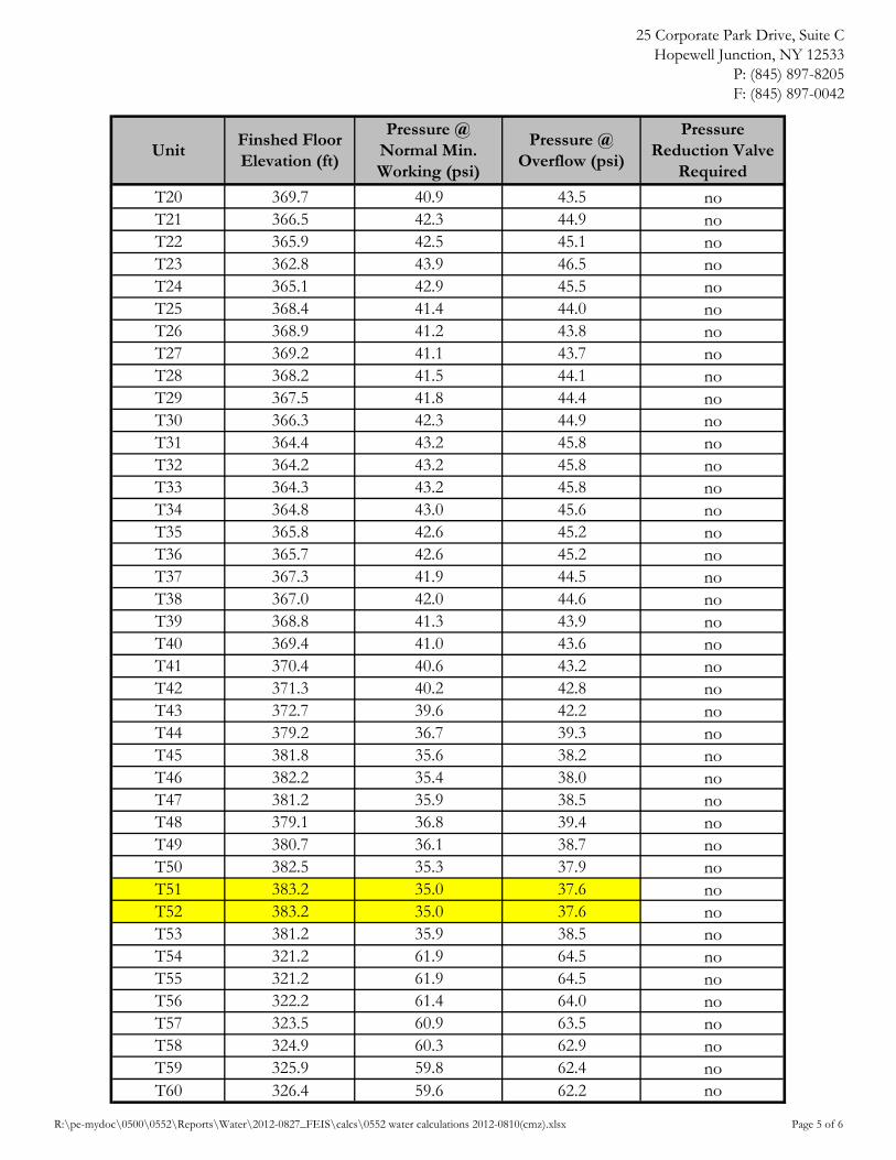
T20 369.7 40.9 43.5 noT21 366.5 42.3 44.9 noT22 365.9 42.5 45.1 noT23 362.8 43.9 46.5 noT24 365.1 42.9 45.5 noT25 368.4 41.4 44.0 noT26 368.9 41.2 43.8 noT27 369.2 41.1 43.7 noT28 368.2 41.5 44.1 noT29 367.5 41.8 44.4 noT30 366.3 42.3 44.9 noT31 364.4 43.2 45.8 noT32 364.2 43.2 45.8 noT33 364.3 43.2 45.8 noT34 364.8 43.0 45.6 noT35 365.8 42.6 45.2 noT36 365.7 42.6 45.2 noT37 367.3 41.9 44.5 noT38 367.0 42.0 44.6 noT39 368.8 41.3 43.9 noT40 369.4 41.0 43.6 noT41 370.4 40.6 43.2 noT42 371.3 40.2 42.8 noT43 372.7 39.6 42.2 noT44 379.2 36.7 39.3 noT45 381.8 35.6 38.2 noT46 382.2 35.4 38.0 noT47 381.2 35.9 38.5 noT48 379.1 36.8 39.4 noT49 380.7 36.1 38.7 noT50 382.5 35.3 37.9 noT51 383.2 35.0 37.6 noT52 383.2 35.0 37.6 noT53 381.2 35.9 38.5 noT54 321.2 61.9 64.5 noT55 321.2 61.9 64.5 noT56 322.2 61.4 64.0 noT57 323.5 60.9 63.5 noT58 324.9 60.3 62.9 noT59 325.9 59.8 62.4 noT60 326.4 59.6 62.2 no
R:\pe-mydoc\0500\0552\Reports\Water\2012-0827_FEIS\calcs\0552 water calculations 2012-0810(cmz).xlsx Page 5 of 6

25 Corporate Park Drive, Suite CHopewell Junction, NY 12533
P: (845) 897-8205F: (845) 897-0042
UnitFinshed Floor Elevation (ft)
Pressure @ Normal Min. Working (psi)
Pressure @ Overflow (psi)
Pressure Reduction Valve
Required
T61 326.3 59.7 62.3 noT62 326.1 59.8 62.4 noT63 325.5 60.0 62.6 noT64 324.8 60.3 62.9 noT65 323.8 60.8 63.4 noT66 322.2 61.4 64.0 noT67 320.7 62.1 64.7 noT68 319.2 62.7 65.3 noT69 317.4 63.5 66.1 noT70 316.8 63.8 66.4 noT71 317.7 63.4 66.0 noT72 319.5 62.6 65.2 noT73 321.2 61.9 64.5 noT74 322.1 61.5 64.1 noT75 323.9 60.7 63.3 noT76 321.7 61.7 64.3 noT77 320.9 62.0 64.6 noT78 320.3 62.3 64.9 noT79 318.8 62.9 65.5 noT80 317.9 63.3 65.9 noT81 317.4 63.5 66.1 noT82 317.3 63.6 66.2 noT83 318.0 63.3 65.9 noT84 319.5 62.6 65.2 noT85 320.2 62.3 64.9 noT86 320.9 62.0 64.6 noT87 322.1 61.5 64.1 noT88 323.8 60.8 63.4 noT89 322.3 61.4 64.0 noT90 321.6 61.7 64.3 noT91 321.2 61.9 64.5 noT92 320.1 62.4 65.0 noT93 320.4 62.2 64.8 no
Notes:= lowest pressure=highest pressure
R:\pe-mydoc\0500\0552\Reports\Water\2012-0827_FEIS\calcs\0552 water calculations 2012-0810(cmz).xlsx Page 6 of 6

SCALE:
DATE:
JOB #:WILLIAM H. POVALL III, P.E.N.Y.S.P.E. LICENSE #075020
25 CORPORATE PARK DR., SUITE CHOPEWELL JUNCTION, NY 12533
TEL.: (845) 897-8205FAX: (845) 897-0042
HILLTOP VILLAGE AT WAPPINGER
WATER SYSTEM ANALYSIS
TOWN OF WAPPINGER DUTCHESS COUNTY, NEW YORK
0552
08/10/12
1"=250'
WSA-1SHEET 1 OF 1

25 Corporate Park Drive, Suite CHopewell Junction, NY 12533
P: (845) 897-8205F: (845) 897-0042
Job Name: Hilltop Village at Wappinger Job No.: 0552Prepared By: CMZ Revised By:Date: 8/10/12 Rev. Date:Reviewed By: WHP Reviewed By:
Water elevation within water storage tanks at:Overflow = 470 ftNormal min working level = 464 ft
Junction Number
Type Elevation (ft)Pressure @
Normal Min. Working (psi)
Pressure @ Overflow (psi)
WaterCAD Pressure (psi)
J-1 Connection 280.0 79.7 82.3 79.61J-2 Tee 307.0 68.0 70.6 67.93J-3 Hydrant 311.7 66.0 68.6 65.89J-4 Hydrant 318.2 63.2 65.8 63.08J-5 Hydrant 312.0 65.9 68.5 65.76J-6 Tee 316.3 64.0 66.6 63.90J-7 Hydrant 313.5 65.2 67.8 65.11J-8 Hydrant 309.0 67.2 69.8 67.06J-9 Hydrant 317.0 63.7 66.3 63.60J-10 Tee 340.8 53.4 56.0 53.30J-11 Hydrant 343.0 52.4 55.0 52.35J-12 Tee 364.4 43.2 45.8 43.09J-13 Hydrant 364.4 43.2 45.8 43.09J-14 Hydrant 356.0 46.8 49.4 46.73J-15 Hydrant 362.8 43.9 46.5 43.78J-16 Tee 362.9 43.8 46.4 43.74J-17 Tee 371.0 40.3 42.9 40.24J-18 Hydrant 373.4 39.3 41.9 39.20J-19 Tee 348.1 50.2 52.8 50.14J-20 Hydrant 339.3 54.0 56.6 53.95J-21 Tee 307.6 67.8 70.4 67.67J-22 Hydrant 286.0 77.1 79.7 77.01J-23 Connection 295.0 73.2 75.8 73.12J-24 Hydrant 307.5 67.8 70.4 67.71J-25 Hydrant 311.2 66.2 68.8 66.11J-26 Hydrant 331.2 57.5 60.1 57.46J-27 Tee 350.9 49.0 51.6 48.93J-28 Tee 355.9 46.8 49.4 46.77J-29 Hydrant 355.5 47.0 49.6 46.94J-30 Hydrant 347.0 50.7 53.3 50.62J-31 Hydrant 347.2 50.6 53.2 50.53J-32 Hydrant 351.0 49.0 51.6 48.89
WATER SYSTEM PRESSURE CALCULATIONS
R:\pe-mydoc\0500\0552\Reports\Water\2012-0827_FEIS\calcs\0552 water calculations 2012-0810(cmz).xlsx Page 1 of 2

25 Corporate Park Drive, Suite CHopewell Junction, NY 12533
P: (845) 897-8205F: (845) 897-0042
Junction Number
Type Elevation (ft)Pressure @
Normal Min. Working (psi)
Pressure @ Overflow (psi)
WaterCAD Pressure (psi)
J-33 Hydrant 363.5 43.6 46.2 43.48J-34 Tee 361.6 44.4 47.0 44.30J-35 Hydrant 350.6 49.1 51.7 49.06J-36 Tee 341.0 53.3 55.9 53.22J-37 Hydrant 348.2 50.2 52.8 50.10
Notes:= lowest pressure=highest pressure
R:\pe-mydoc\0500\0552\Reports\Water\2012-0827_FEIS\calcs\0552 water calculations 2012-0810(cmz).xlsx Page 2 of 2

Hilltop Village at Wappinger Povall Engineering, PLLC
Analysis ResultsScenario: Base
Steady State Analysis
r:\...\watercad\0552 wsa section 1 2012-0806.wcd WaterCAD v7.0 [07.00.027.00] Page 1 of 2
Title:Project Engineer:Project Date:Comments:
Hilltop Village at WappingerPovall Engineering, PLLC08/01/12 07:37:41 AM
Scenario Summary
Scenario Base
Active Topology Alternative Base-Active Topology
Physical Alternative Base-Physical
Demand Alternative Base-Demand
Initial Settings Alternative Base-Initial Settings
Operational Alternative Base-Operational
Age Alternative Base-Age Alternative
Constituent Alternative Base-Constituent
Trace Alternative Base-Trace Alternative
Fire Flow Alternative Base-Fire Flow
Capital Cost Alternative Base-Capital Cost
Energy Cost Alternative Base-Energy Cost
User Data Alternative Base-User Data
Liquid Characteristics
Liquid Water at 20C(68F) Specific Gravity 1.00
Kinematic Viscosity 1.0804e-5 ft²/s
Network Inventory
Pressure Pipes 23 Number of Tanks 1
Number of Reservoirs 0 - Constant Area: 1
Number of Pressure Junctio 21 - Variable Area: 0
Number of Pumps 0 Number of Valves 0
- Constant Power: 0 - FCV's: 0
- One Point (Design Point): 0 - PBV's: 0
- Standard (3 Point): 0 - PRV's: 0
- Standard Extended: 0 - PSV's: 0
- Custom Extended: 0 - TCV's: 0
- Multiple Point: 0 - GPV's: 0
Number of Spot Elevations 0
Pressure Pipes Inventory
8.0 in 15,228.00 ft
Total Length 15,228.00 ft
Pressure Junctions @ 0.00 hr
Label CalculatedHydraulic Grade
(ft)
Pressure(psi)
PressureHead
(ft)
Demand(Calculated)
(gpm)
J-1 464.00 79.61 184.00 0.00
J-2 464.00 67.93 157.00 0.00
J-3 464.00 65.89 152.30 0.00
J-4 464.00 63.08 145.80 0.00
J-5 464.00 65.76 152.00 0.00
J-6 464.00 63.90 147.70 0.00
J-7 464.00 65.11 150.50 0.00
J-8 464.00 67.06 155.00 0.00

Hilltop Village at Wappinger Povall Engineering, PLLC
Analysis ResultsScenario: Base
Steady State Analysis
r:\...\watercad\0552 wsa section 1 2012-0806.wcd WaterCAD v7.0 [07.00.027.00] Page 2 of 2
Pressure Junctions @ 0.00 hr
Label CalculatedHydraulic Grade
(ft)
Pressure(psi)
PressureHead
(ft)
Demand(Calculated)
(gpm)
J-9 464.00 63.60 147.00 0.00
J-10 464.00 53.30 123.20 0.00
J-11 464.00 52.35 121.00 0.00
J-12 464.00 43.09 99.60 0.00
J-16 464.00 43.74 101.10 0.00
J-17 464.00 40.24 93.00 0.00
J-18 464.00 39.20 90.60 0.00
J-19 464.00 50.14 115.90 0.00
J-20 464.00 53.95 124.70 0.00
J-21 464.00 67.67 156.40 0.00
J-22 464.00 77.01 178.00 0.00
J-23 464.00 73.12 169.00 0.00
Hilltop Village at Wappinger Povall Engineering, PLLC
Analysis ResultsScenario: Base
Steady State Analysis
r:\...\watercad\0552 wsa section 2 2012-0806.wcd WaterCAD v7.0 [07.00.027.00] Page 1 of 1
Title:Project Engineer:Project Date:Comments:
Hilltop Village at WappingerPovall Engineering, PLLC08/01/12 07:37:41 AM
Scenario Summary
Scenario Base
Active Topology Alternative Base-Active Topology
Physical Alternative Base-Physical
Demand Alternative Base-Demand
Initial Settings Alternative Base-Initial Settings
Operational Alternative Base-Operational
Age Alternative Base-Age Alternative
Constituent Alternative Base-Constituent
Trace Alternative Base-Trace Alternative
Fire Flow Alternative Base-Fire Flow
Capital Cost Alternative Base-Capital Cost
Energy Cost Alternative Base-Energy Cost
User Data Alternative Base-User Data
Liquid Characteristics
Liquid Water at 20C(68F) Specific Gravity 1.00
Kinematic Viscosity 1.0804e-5 ft²/s
Network Inventory
Pressure Pipes 25 Number of Tanks 1
Number of Reservoirs 0 - Constant Area: 1
Number of Pressure Junctio 22 - Variable Area: 0
Number of Pumps 0 Number of Valves 0
- Constant Power: 0 - FCV's: 0
- One Point (Design Point): 0 - PBV's: 0
- Standard (3 Point): 0 - PRV's: 0
- Standard Extended: 0 - PSV's: 0
- Custom Extended: 0 - TCV's: 0
- Multiple Point: 0 - GPV's: 0
Number of Spot Elevations 0
Pressure Pipes Inventory
8.0 in 11,253.00 ft
Total Length 11,253.00 ft
Pressure Junctions @ 0.00 hr
Label CalculatedHydraulic Grade
(ft)
Pressure(psi)
PressureHead
(ft)
Demand(Calculated)
(gpm)
J-13 464.00 43.09 99.60 0.00
J-14 464.00 46.73 108.00 0.00
J-15 464.00 43.78 101.20 0.00
J-34 464.00 44.30 102.40 0.00
J-35 464.00 49.06 113.40 0.00
J-36 464.00 53.22 123.00 0.00
J-37 464.00 50.10 115.80 0.00

Hilltop Village at Wappinger Povall Engineering, PLLC
Analysis ResultsScenario: Base
Steady State Analysis
r:\...\watercad\0552 wsa section 3 2012-0806.wcd WaterCAD v7.0 [07.00.027.00] Page 1 of 1
Title:Project Engineer:Project Date:Comments:
Hilltop Village at WappingerPovall Engineering, PLLC08/01/12 07:37:41 AM
Scenario Summary
Scenario Base
Active Topology Alternative Base-Active Topology
Physical Alternative Base-Physical
Demand Alternative Base-Demand
Initial Settings Alternative Base-Initial Settings
Operational Alternative Base-Operational
Age Alternative Base-Age Alternative
Constituent Alternative Base-Constituent
Trace Alternative Base-Trace Alternative
Fire Flow Alternative Base-Fire Flow
Capital Cost Alternative Base-Capital Cost
Energy Cost Alternative Base-Energy Cost
User Data Alternative Base-User Data
Liquid Characteristics
Liquid Water at 20C(68F) Specific Gravity 1.00
Kinematic Viscosity 1.0804e-5 ft²/s
Network Inventory
Pressure Pipes 18 Number of Tanks 1
Number of Reservoirs 0 - Constant Area: 1
Number of Pressure Junctio 16 - Variable Area: 0
Number of Pumps 0 Number of Valves 0
- Constant Power: 0 - FCV's: 0
- One Point (Design Point): 0 - PBV's: 0
- Standard (3 Point): 0 - PRV's: 0
- Standard Extended: 0 - PSV's: 0
- Custom Extended: 0 - TCV's: 0
- Multiple Point: 0 - GPV's: 0
Number of Spot Elevations 0
Pressure Pipes Inventory
8.0 in 13,372.00 ft
Total Length 13,372.00 ft
Pressure Junctions @ 0.00 hr
Label CalculatedHydraulic Grade
(ft)
Pressure(psi)
PressureHead
(ft)
Demand(Calculated)
(gpm)
J-24 464.00 67.71 156.50 0.00
J-25 464.00 66.11 152.80 0.00
J-26 464.00 57.46 132.80 0.00
J-27 464.00 48.93 113.10 0.00
J-28 464.00 46.77 108.10 0.00
J-29 464.00 46.94 108.50 0.00
J-30 464.00 50.62 117.00 0.00
J-31 464.00 50.53 116.80 0.00

Hilltop Village at Wappinger Povall Engineering, PLLC
Analysis ResultsScenario: Base
Steady State Analysis
r:\...\watercad\0552 wsa section 4 2012-0806.wcd WaterCAD v7.0 [07.00.027.00] Page 1 of 1
Title:Project Engineer:Project Date:Comments:
Hilltop Village at WappingerPovall Engineering, PLLC08/01/12 07:37:41 AM
Scenario Summary
Scenario Base
Active Topology Alternative Base-Active Topology
Physical Alternative Base-Physical
Demand Alternative Base-Demand
Initial Settings Alternative Base-Initial Settings
Operational Alternative Base-Operational
Age Alternative Base-Age Alternative
Constituent Alternative Base-Constituent
Trace Alternative Base-Trace Alternative
Fire Flow Alternative Base-Fire Flow
Capital Cost Alternative Base-Capital Cost
Energy Cost Alternative Base-Energy Cost
User Data Alternative Base-User Data
Liquid Characteristics
Liquid Water at 20C(68F) Specific Gravity 1.00
Kinematic Viscosity 1.0804e-5 ft²/s
Network Inventory
Pressure Pipes 24 Number of Tanks 1
Number of Reservoirs 0 - Constant Area: 1
Number of Pressure Junctio 22 - Variable Area: 0
Number of Pumps 0 Number of Valves 0
- Constant Power: 0 - FCV's: 0
- One Point (Design Point): 0 - PBV's: 0
- Standard (3 Point): 0 - PRV's: 0
- Standard Extended: 0 - PSV's: 0
- Custom Extended: 0 - TCV's: 0
- Multiple Point: 0 - GPV's: 0
Number of Spot Elevations 0
Pressure Pipes Inventory
8.0 in 10,778.00 ft
Total Length 10,778.00 ft
Pressure Junctions @ 0.00 hr
Label CalculatedHydraulic Grade
(ft)
Pressure(psi)
PressureHead
(ft)
Demand(Calculated)
(gpm)
J-32 464.00 48.89 113.00 0.00
J-33 464.00 43.48 100.50 0.00

25 Corporate Park Drive, Suite CHopewell Junction, NY 12533
P: (845) 897-8205F: (845) 897-0042
Job Name: Hilltop Village at Wappinger Job No.: 0552Prepared By: CMZ Revised By:Date: 8/10/12 Rev. Date:Reviewed By: WHP Reviewed By:
Normal working pressure range = approx. 60 to 80 psiRequired minimum normal working pressure = 35 psi
Junction Number
TypeOriginal
WaterCAD Pressure (psi)
Avg. Demand (gpm)
WaterCAD Pressure (psi)
Pressure Reduction Valve
Required
J-1 Connection 79.61 0.00 79.59 noJ-2 Tee 67.93 1.39 67.91 noJ-3 Hydrant 65.89 1.67 65.88 noJ-4 Hydrant 63.08 0.28 63.06 noJ-5 Hydrant 65.76 0.83 65.75 noJ-6 Tee 63.90 1.39 63.88 noJ-7 Hydrant 65.11 0.00 65.10 noJ-8 Hydrant 67.06 0.00 67.04 noJ-9 Hydrant 63.60 0.90 63.58 noJ-10 Tee 53.30 0.22 53.28 noJ-11 Hydrant 52.35 1.78 52.33 noJ-12 Tee 43.09 1.61 43.07 noJ-13 Hydrant 43.09 2.08 43.06 noJ-14 Hydrant 46.73 1.39 46.69 noJ-15 Hydrant 43.78 0.00 43.75 noJ-16 Tee 43.74 1.33 43.72 noJ-17 Tee 40.24 0.00 40.22 noJ-18 Hydrant 39.20 0.00 39.18 noJ-19 Tee 50.14 0.67 50.13 noJ-20 Hydrant 53.95 4.22 53.93 noJ-21 Tee 67.67 0.00 67.65 noJ-22 Hydrant 77.01 0.00 76.99 noJ-23 Connection 73.12 0.00 73.10 noJ-24 Hydrant 67.71 2.44 67.64 noJ-25 Hydrant 66.11 2.89 66.04 noJ-26 Hydrant 57.46 2.22 57.39 noJ-27 Tee 48.93 2.67 48.86 noJ-28 Tee 46.77 2.22 46.70 noJ-29 Hydrant 46.94 1.78 46.87 noJ-30 Hydrant 50.62 2.67 50.55 noJ-31 Hydrant 50.53 0.00 50.46 noJ-32 Hydrant 48.89 2.22 48.86 noJ-33 Hydrant 43.48 0.00 43.45 no
WATER SYSTEM PRESSURE CALCULATIONS - AVERAGE FLOW
R:\pe-mydoc\0500\0552\Reports\Water\2012-0827_FEIS\calcs\0552 water calculations 2012-0810(cmz).xlsx Page 1 of 2

25 Corporate Park Drive, Suite CHopewell Junction, NY 12533
P: (845) 897-8205F: (845) 897-0042
Junction Number
TypeOriginal
WaterCAD Pressure (psi)
Avg. Demand (gpm)
WaterCAD Pressure (psi)
Pressure Reduction Valve
Required
J-34 Tee 44.30 1.11 44.27 noJ-35 Hydrant 49.06 0.67 49.03 noJ-36 Tee 53.22 0.83 53.19 noJ-37 Hydrant 50.10 1.67 50.07 no
Notes:= lowest pressure=highest pressure
R:\pe-mydoc\0500\0552\Reports\Water\2012-0827_FEIS\calcs\0552 water calculations 2012-0810(cmz).xlsx Page 2 of 2

Hilltop Village at Wappinger Povall Engineering, PLLC
Analysis ResultsScenario: Base
Steady State Analysis
r:\...\watercad\0552 wsa section 1 2012-0806.wcd WaterCAD v7.0 [07.00.027.00] Page 1 of 2
Title:Project Engineer:Project Date:Comments:
Hilltop Village at WappingerPovall Engineering, PLLC08/01/12 07:37:41 AM
Scenario Summary
Scenario Base
Active Topology Alternative Base-Active Topology
Physical Alternative Base-Physical
Demand Alternative Demand Avg
Initial Settings Alternative Base-Initial Settings
Operational Alternative Base-Operational
Age Alternative Base-Age Alternative
Constituent Alternative Base-Constituent
Trace Alternative Base-Trace Alternative
Fire Flow Alternative Base-Fire Flow
Capital Cost Alternative Base-Capital Cost
Energy Cost Alternative Base-Energy Cost
User Data Alternative Base-User Data
Liquid Characteristics
Liquid Water at 20C(68F) Specific Gravity 1.00
Kinematic Viscosity 1.0804e-5 ft²/s
Network Inventory
Pressure Pipes 23 Number of Tanks 1
Number of Reservoirs 0 - Constant Area: 1
Number of Pressure Junctio 21 - Variable Area: 0
Number of Pumps 0 Number of Valves 0
- Constant Power: 0 - FCV's: 0
- One Point (Design Point): 0 - PBV's: 0
- Standard (3 Point): 0 - PRV's: 0
- Standard Extended: 0 - PSV's: 0
- Custom Extended: 0 - TCV's: 0
- Multiple Point: 0 - GPV's: 0
Number of Spot Elevations 0
Pressure Pipes Inventory
8.0 in 15,228.00 ft
Total Length 15,228.00 ft
Pressure Junctions @ 0.00 hr
Label CalculatedHydraulic Grade
(ft)
Pressure(psi)
PressureHead
(ft)
Demand(Calculated)
(gpm)
J-1 463.96 79.59 183.96 0.00
J-2 463.96 67.91 156.96 1.39
J-3 463.96 65.88 152.26 1.67
J-4 463.96 63.06 145.76 0.28
J-5 463.96 65.75 151.96 0.83
J-6 463.96 63.88 147.66 1.39
J-7 463.96 65.10 150.46 0.00
J-8 463.96 67.04 154.96 0.00

Hilltop Village at Wappinger Povall Engineering, PLLC
Analysis ResultsScenario: Base
Steady State Analysis
r:\...\watercad\0552 wsa section 1 2012-0806.wcd WaterCAD v7.0 [07.00.027.00] Page 2 of 2
Pressure Junctions @ 0.00 hr
Label CalculatedHydraulic Grade
(ft)
Pressure(psi)
PressureHead
(ft)
Demand(Calculated)
(gpm)
J-9 463.96 63.58 146.96 0.90
J-10 463.96 53.28 123.16 0.22
J-11 463.96 52.33 120.96 1.78
J-12 463.96 43.07 99.56 1.61
J-16 463.96 43.72 101.06 1.33
J-17 463.96 40.22 92.96 0.00
J-18 463.96 39.18 90.56 0.00
J-19 463.96 50.13 115.86 0.67
J-20 463.96 53.93 124.66 4.22
J-21 463.96 67.65 156.36 0.00
J-22 463.96 76.99 177.96 0.00
J-23 463.96 73.10 168.96 0.00
Hilltop Village at Wappinger Povall Engineering, PLLC
Analysis ResultsScenario: Base
Steady State Analysis
r:\...\watercad\0552 wsa section 2 2012-0806.wcd WaterCAD v7.0 [07.00.027.00] Page 1 of 1
Title:Project Engineer:Project Date:Comments:
Hilltop Village at WappingerPovall Engineering, PLLC08/01/12 07:37:41 AM
Scenario Summary
Scenario Base
Active Topology Alternative Base-Active Topology
Physical Alternative Base-Physical
Demand Alternative Demand avg
Initial Settings Alternative Base-Initial Settings
Operational Alternative Base-Operational
Age Alternative Base-Age Alternative
Constituent Alternative Base-Constituent
Trace Alternative Base-Trace Alternative
Fire Flow Alternative Base-Fire Flow
Capital Cost Alternative Base-Capital Cost
Energy Cost Alternative Base-Energy Cost
User Data Alternative Base-User Data
Liquid Characteristics
Liquid Water at 20C(68F) Specific Gravity 1.00
Kinematic Viscosity 1.0804e-5 ft²/s
Network Inventory
Pressure Pipes 25 Number of Tanks 1
Number of Reservoirs 0 - Constant Area: 1
Number of Pressure Junctio 22 - Variable Area: 0
Number of Pumps 0 Number of Valves 0
- Constant Power: 0 - FCV's: 0
- One Point (Design Point): 0 - PBV's: 0
- Standard (3 Point): 0 - PRV's: 0
- Standard Extended: 0 - PSV's: 0
- Custom Extended: 0 - TCV's: 0
- Multiple Point: 0 - GPV's: 0
Number of Spot Elevations 0
Pressure Pipes Inventory
8.0 in 11,253.00 ft
Total Length 11,253.00 ft
Pressure Junctions @ 0.00 hr
Label CalculatedHydraulic Grade
(ft)
Pressure(psi)
PressureHead
(ft)
Demand(Calculated)
(gpm)
J-13 463.93 43.06 99.53 2.08
J-14 463.93 46.69 107.93 1.39
J-15 463.93 43.75 101.13 0.00
J-34 463.93 44.27 102.33 1.11
J-35 463.93 49.03 113.33 0.67
J-36 463.93 53.19 122.93 0.83
J-37 463.93 50.07 115.73 1.67

Hilltop Village at Wappinger Povall Engineering, PLLC
Analysis ResultsScenario: Base
Steady State Analysis
r:\...\watercad\0552 wsa section 3 2012-0806.wcd WaterCAD v7.0 [07.00.027.00] Page 1 of 1
Title:Project Engineer:Project Date:Comments:
Hilltop Village at WappingerPovall Engineering, PLLC08/01/12 07:37:41 AM
Scenario Summary
Scenario Base
Active Topology Alternative Base-Active Topology
Physical Alternative Base-Physical
Demand Alternative Demand avg
Initial Settings Alternative Base-Initial Settings
Operational Alternative Base-Operational
Age Alternative Base-Age Alternative
Constituent Alternative Base-Constituent
Trace Alternative Base-Trace Alternative
Fire Flow Alternative Base-Fire Flow
Capital Cost Alternative Base-Capital Cost
Energy Cost Alternative Base-Energy Cost
User Data Alternative Base-User Data
Liquid Characteristics
Liquid Water at 20C(68F) Specific Gravity 1.00
Kinematic Viscosity 1.0804e-5 ft²/s
Network Inventory
Pressure Pipes 18 Number of Tanks 1
Number of Reservoirs 0 - Constant Area: 1
Number of Pressure Junctio 16 - Variable Area: 0
Number of Pumps 0 Number of Valves 0
- Constant Power: 0 - FCV's: 0
- One Point (Design Point): 0 - PBV's: 0
- Standard (3 Point): 0 - PRV's: 0
- Standard Extended: 0 - PSV's: 0
- Custom Extended: 0 - TCV's: 0
- Multiple Point: 0 - GPV's: 0
Number of Spot Elevations 0
Pressure Pipes Inventory
8.0 in 13,372.00 ft
Total Length 13,372.00 ft
Pressure Junctions @ 0.00 hr
Label CalculatedHydraulic Grade
(ft)
Pressure(psi)
PressureHead
(ft)
Demand(Calculated)
(gpm)
J-24 463.84 67.64 156.34 2.44
J-25 463.84 66.04 152.64 2.89
J-26 463.84 57.39 132.64 2.22
J-27 463.84 48.86 112.94 2.67
J-28 463.84 46.70 107.94 2.22
J-29 463.84 46.87 108.34 1.78
J-30 463.84 50.55 116.84 2.67
J-31 463.84 50.46 116.64 0.00
Hilltop Village at Wappinger Povall Engineering, PLLC
Analysis ResultsScenario: Base
Steady State Analysis
r:\...\watercad\0552 wsa section 4 2012-0806.wcd WaterCAD v7.0 [07.00.027.00] Page 1 of 1
Title:Project Engineer:Project Date:Comments:
Hilltop Village at WappingerPovall Engineering, PLLC08/01/12 07:37:41 AM
Scenario Summary
Scenario Base
Active Topology Alternative Base-Active Topology
Physical Alternative Base-Physical
Demand Alternative Demand avg
Initial Settings Alternative Base-Initial Settings
Operational Alternative Base-Operational
Age Alternative Base-Age Alternative
Constituent Alternative Base-Constituent
Trace Alternative Base-Trace Alternative
Fire Flow Alternative Base-Fire Flow
Capital Cost Alternative Base-Capital Cost
Energy Cost Alternative Base-Energy Cost
User Data Alternative Base-User Data
Liquid Characteristics
Liquid Water at 20C(68F) Specific Gravity 1.00
Kinematic Viscosity 1.0804e-5 ft²/s
Network Inventory
Pressure Pipes 24 Number of Tanks 1
Number of Reservoirs 0 - Constant Area: 1
Number of Pressure Junctio 22 - Variable Area: 0
Number of Pumps 0 Number of Valves 0
- Constant Power: 0 - FCV's: 0
- One Point (Design Point): 0 - PBV's: 0
- Standard (3 Point): 0 - PRV's: 0
- Standard Extended: 0 - PSV's: 0
- Custom Extended: 0 - TCV's: 0
- Multiple Point: 0 - GPV's: 0
Number of Spot Elevations 0
Pressure Pipes Inventory
8.0 in 10,778.00 ft
Total Length 10,778.00 ft
Pressure Junctions @ 0.00 hr
Label CalculatedHydraulic Grade
(ft)
Pressure(psi)
PressureHead
(ft)
Demand(Calculated)
(gpm)
J-32 463.92 48.86 112.92 2.22
J-33 463.92 43.45 100.42 0.00

25 Corporate Park Drive, Suite CHopewell Junction, NY 12533
P: (845) 897-8205F: (845) 897-0042
Job Name: Hilltop Village at Wappinger Job No.: 0552Prepared By: CMZ Revised By:Date: 8/10/12 Rev. Date:Reviewed By: WHP Reviewed By:
Normal working pressure range = approx. 60 to 80 psiRequired minimum normal working pressure = 35 psi
Junction Number
TypeOriginal
WaterCAD Pressure (psi)
Avg. Demand (gpm)
WaterCAD Pressure (psi)
Pressure Reduction Valve
Required
J-1 Connection 79.61 0.00 79.38 noJ-2 Tee 67.93 5.56 67.69 noJ-3 Hydrant 65.89 6.68 65.66 noJ-4 Hydrant 63.08 1.12 62.85 noJ-5 Hydrant 65.76 3.32 65.56 noJ-6 Tee 63.90 5.56 63.67 noJ-7 Hydrant 65.11 0.00 64.88 noJ-8 Hydrant 67.06 0.00 66.82 noJ-9 Hydrant 63.60 3.60 63.36 noJ-10 Tee 53.30 0.88 53.06 noJ-11 Hydrant 52.35 7.12 52.10 noJ-12 Tee 43.09 6.44 42.84 noJ-13 Hydrant 43.09 8.32 42.68 no
WATER SYSTEM PRESSURE CALCULATIONS - PEAK FLOW
J-14 Hydrant 46.73 5.56 46.31 noJ-15 Hydrant 43.78 0.00 43.37 noJ-16 Tee 43.74 5.32 43.49 noJ-17 Tee 40.24 0.00 39.99 noJ-18 Hydrant 39.20 0.00 38.95 noJ-19 Tee 50.14 2.68 49.90 noJ-20 Hydrant 53.95 16.88 53.70 noJ-21 Tee 67.67 0.00 67.42 noJ-22 Hydrant 77.01 0.00 72.88 noJ-23 Connection 73.12 0.00 73.10 noJ-24 Hydrant 67.71 9.76 66.82 noJ-25 Hydrant 66.11 11.56 65.21 noJ-26 Hydrant 57.46 8.88 56.55 noJ-27 Tee 48.93 10.68 48.03 noJ-28 Tee 46.77 8.88 45.86 noJ-29 Hydrant 46.94 7.12 46.03 noJ-30 Hydrant 50.62 10.68 49.71 noJ-31 Hydrant 50.53 0.00 49.63 noJ-32 Hydrant 48.89 8.88 48.45 noJ-33 Hydrant 43.48 0.00 43.04 no
R:\pe-mydoc\0500\0552\Reports\Water\2012-0827_FEIS\calcs\0552 water calculations 2012-0810(cmz).xlsx Page 1 of 2
25 Corporate Park Drive, Suite CHopewell Junction, NY 12533
P: (845) 897-8205F: (845) 897-0042
Junction Number
TypeOriginal
WaterCAD Pressure (psi)
Avg. Demand (gpm)
WaterCAD Pressure (psi)
Pressure Reduction Valve
Required
J-34 Tee 44.30 4.44 43.89 noJ-35 Hydrant 49.06 2.68 48.65 noJ-36 Tee 53.22 3.32 52.81 noJ-37 Hydrant 50.10 6.68 49.69 no
Notes:= lowest pressure=highest pressure
R:\pe-mydoc\0500\0552\Reports\Water\2012-0827_FEIS\calcs\0552 water calculations 2012-0810(cmz).xlsx Page 2 of 2

Hilltop Village at Wappinger Povall Engineering, PLLC
Analysis ResultsScenario: Base
Steady State Analysis
r:\...\watercad\0552 wsa section 1 2012-0806.wcd WaterCAD v7.0 [07.00.027.00] Page 1 of 2
Title:Project Engineer:Project Date:Comments:
Hilltop Village at WappingerPovall Engineering, PLLC08/01/12 07:37:41 AM
Scenario Summary
Scenario Base
Active Topology Alternative Base-Active Topology
Physical Alternative Base-Physical
Demand Alternative Demand Peak
Initial Settings Alternative Base-Initial Settings
Operational Alternative Base-Operational
Age Alternative Base-Age Alternative
Constituent Alternative Base-Constituent
Trace Alternative Base-Trace Alternative
Fire Flow Alternative Base-Fire Flow
Capital Cost Alternative Base-Capital Cost
Energy Cost Alternative Base-Energy Cost
User Data Alternative Base-User Data
Liquid Characteristics
Liquid Water at 20C(68F) Specific Gravity 1.00
Kinematic Viscosity 1.0804e-5 ft²/s
Network Inventory
Pressure Pipes 23 Number of Tanks 1
Number of Reservoirs 0 - Constant Area: 1
Number of Pressure Junctio 21 - Variable Area: 0
Number of Pumps 0 Number of Valves 0
- Constant Power: 0 - FCV's: 0
- One Point (Design Point): 0 - PBV's: 0
- Standard (3 Point): 0 - PRV's: 0
- Standard Extended: 0 - PSV's: 0
- Custom Extended: 0 - TCV's: 0
- Multiple Point: 0 - GPV's: 0
Number of Spot Elevations 0
Pressure Pipes Inventory
8.0 in 15,228.00 ft
Total Length 15,228.00 ft
Pressure Junctions @ 0.00 hr
Label CalculatedHydraulic Grade
(ft)
Pressure(psi)
PressureHead
(ft)
Demand(Calculated)
(gpm)
J-1 463.48 79.38 183.48 0.00
J-2 463.46 67.69 156.46 5.56
J-3 463.46 65.66 151.76 6.68
J-4 463.46 62.85 145.26 1.12
J-5 463.46 65.53 151.46 3.32
J-6 463.46 63.67 147.16 5.56
J-7 463.45 64.88 149.95 0.00
J-8 463.44 66.82 154.44 0.00

Hilltop Village at Wappinger Povall Engineering, PLLC
Analysis ResultsScenario: Base
Steady State Analysis
r:\...\watercad\0552 wsa section 1 2012-0806.wcd WaterCAD v7.0 [07.00.027.00] Page 2 of 2
Pressure Junctions @ 0.00 hr
Label CalculatedHydraulic Grade
(ft)
Pressure(psi)
PressureHead
(ft)
Demand(Calculated)
(gpm)
J-9 463.43 63.36 146.43 3.60
J-10 463.43 53.06 122.63 0.88
J-11 463.43 52.10 120.43 7.12
J-12 463.43 42.84 99.03 6.44
J-16 463.43 43.49 100.53 5.32
J-17 463.43 39.99 92.43 0.00
J-18 463.43 38.95 90.03 0.00
J-19 463.43 49.90 115.33 2.68
J-20 463.43 53.70 124.13 16.88
J-21 463.44 67.42 155.84 0.00
J-22 463.44 76.77 177.44 0.00
J-23 463.45 72.88 168.45 0.00

Hilltop Village at Wappinger Povall Engineering, PLLC
Analysis ResultsScenario: Base
Steady State Analysis
r:\...\watercad\0552 wsa section 2 2012-0806.wcd WaterCAD v7.0 [07.00.027.00] Page 1 of 1
Title:Project Engineer:Project Date:Comments:
Hilltop Village at WappingerPovall Engineering, PLLC08/01/12 07:37:41 AM
Scenario Summary
Scenario Base
Active Topology Alternative Base-Active Topology
Physical Alternative Base-Physical
Demand Alternative Demand peak
Initial Settings Alternative Base-Initial Settings
Operational Alternative Base-Operational
Age Alternative Base-Age Alternative
Constituent Alternative Base-Constituent
Trace Alternative Base-Trace Alternative
Fire Flow Alternative Base-Fire Flow
Capital Cost Alternative Base-Capital Cost
Energy Cost Alternative Base-Energy Cost
User Data Alternative Base-User Data
Liquid Characteristics
Liquid Water at 20C(68F) Specific Gravity 1.00
Kinematic Viscosity 1.0804e-5 ft²/s
Network Inventory
Pressure Pipes 25 Number of Tanks 1
Number of Reservoirs 0 - Constant Area: 1
Number of Pressure Junctio 22 - Variable Area: 0
Number of Pumps 0 Number of Valves 0
- Constant Power: 0 - FCV's: 0
- One Point (Design Point): 0 - PBV's: 0
- Standard (3 Point): 0 - PRV's: 0
- Standard Extended: 0 - PSV's: 0
- Custom Extended: 0 - TCV's: 0
- Multiple Point: 0 - GPV's: 0
Number of Spot Elevations 0
Pressure Pipes Inventory
8.0 in 11,253.00 ft
Total Length 11,253.00 ft
Pressure Junctions @ 0.00 hr
Label CalculatedHydraulic Grade
(ft)
Pressure(psi)
PressureHead
(ft)
Demand(Calculated)
(gpm)
J-13 463.04 42.68 98.64 8.32
J-14 463.04 46.31 107.04 5.56
J-15 463.04 43.37 100.24 0.00
J-34 463.05 43.89 101.45 4.44
J-35 463.05 48.65 112.45 2.68
J-36 463.05 52.81 122.05 3.32
J-37 463.05 49.69 114.85 6.68

Hilltop Village at Wappinger Povall Engineering, PLLC
Analysis ResultsScenario: Base
Steady State Analysis
r:\...\watercad\0552 wsa section 3 2012-0806.wcd WaterCAD v7.0 [07.00.027.00] Page 1 of 1
Title:Project Engineer:Project Date:Comments:
Hilltop Village at WappingerPovall Engineering, PLLC08/01/12 07:37:41 AM
Scenario Summary
Scenario Base
Active Topology Alternative Base-Active Topology
Physical Alternative Base-Physical
Demand Alternative Demand peak
Initial Settings Alternative Base-Initial Settings
Operational Alternative Base-Operational
Age Alternative Base-Age Alternative
Constituent Alternative Base-Constituent
Trace Alternative Base-Trace Alternative
Fire Flow Alternative Base-Fire Flow
Capital Cost Alternative Base-Capital Cost
Energy Cost Alternative Base-Energy Cost
User Data Alternative Base-User Data
Liquid Characteristics
Liquid Water at 20C(68F) Specific Gravity 1.00
Kinematic Viscosity 1.0804e-5 ft²/s
Network Inventory
Pressure Pipes 18 Number of Tanks 1
Number of Reservoirs 0 - Constant Area: 1
Number of Pressure Junctio 16 - Variable Area: 0
Number of Pumps 0 Number of Valves 0
- Constant Power: 0 - FCV's: 0
- One Point (Design Point): 0 - PBV's: 0
- Standard (3 Point): 0 - PRV's: 0
- Standard Extended: 0 - PSV's: 0
- Custom Extended: 0 - TCV's: 0
- Multiple Point: 0 - GPV's: 0
Number of Spot Elevations 0
Pressure Pipes Inventory
8.0 in 13,372.00 ft
Total Length 13,372.00 ft
Pressure Junctions @ 0.00 hr
Label CalculatedHydraulic Grade
(ft)
Pressure(psi)
PressureHead
(ft)
Demand(Calculated)
(gpm)
J-24 461.94 66.82 154.44 9.76
J-25 461.92 65.21 150.72 11.56
J-26 461.91 56.55 130.71 8.88
J-27 461.90 48.03 111.00 10.68
J-28 461.90 45.86 106.00 8.88
J-29 461.90 46.03 106.40 7.12
J-30 461.90 49.71 114.90 10.68
J-31 461.90 49.63 114.70 0.00

Hilltop Village at Wappinger Povall Engineering, PLLC
Analysis ResultsScenario: Base
Steady State Analysis
r:\...\watercad\0552 wsa section 4 2012-0806.wcd WaterCAD v7.0 [07.00.027.00] Page 1 of 1
Title:Project Engineer:Project Date:Comments:
Hilltop Village at WappingerPovall Engineering, PLLC08/01/12 07:37:41 AM
Scenario Summary
Scenario Base
Active Topology Alternative Base-Active Topology
Physical Alternative Base-Physical
Demand Alternative Demand peak
Initial Settings Alternative Base-Initial Settings
Operational Alternative Base-Operational
Age Alternative Base-Age Alternative
Constituent Alternative Base-Constituent
Trace Alternative Base-Trace Alternative
Fire Flow Alternative Base-Fire Flow
Capital Cost Alternative Base-Capital Cost
Energy Cost Alternative Base-Energy Cost
User Data Alternative Base-User Data
Liquid Characteristics
Liquid Water at 20C(68F) Specific Gravity 1.00
Kinematic Viscosity 1.0804e-5 ft²/s
Network Inventory
Pressure Pipes 24 Number of Tanks 1
Number of Reservoirs 0 - Constant Area: 1
Number of Pressure Junctio 22 - Variable Area: 0
Number of Pumps 0 Number of Valves 0
- Constant Power: 0 - FCV's: 0
- One Point (Design Point): 0 - PBV's: 0
- Standard (3 Point): 0 - PRV's: 0
- Standard Extended: 0 - PSV's: 0
- Custom Extended: 0 - TCV's: 0
- Multiple Point: 0 - GPV's: 0
Number of Spot Elevations 0
Pressure Pipes Inventory
8.0 in 10,778.00 ft
Total Length 10,778.00 ft
Pressure Junctions @ 0.00 hr
Label CalculatedHydraulic Grade
(ft)
Pressure(psi)
PressureHead
(ft)
Demand(Calculated)
(gpm)
J-32 462.99 48.45 111.99 8.88
J-33 462.99 43.04 99.49 0.00

25 Corporate Park Drive, Suite CHopewell Junction, NY 12533
P: (845) 897-8205F: (845) 897-0042
Job Name: Hilltop Village at Wappinger Job No.: 0552Prepared By: CMZ Revised By:Date: 8/10/12 Rev. Date:Reviewed By: WHP Reviewed By:
Required minimum normal working pressure = 35 psiMin. pressure at all points at all flow conditions = 20 psi
Junction Number
TypeOriginal
WaterCAD Pressure (psi)
Fire Flow WaterCAD
Pressure (psi)
< Normal Working Pressure?
< Minimum Pressure?
J-1 Connection 79.61 75.31 no noJ-2 Tee 67.93 63.60 no noJ-3 Hydrant 65.89 61.48 no noJ-4 Hydrant 63.08 58.71 no noJ-5 Hydrant 65.76 61.39 no noJ-6 Tee 63.90 59.56 no noJ-7 Hydrant 65.11 60.76 no noJ-8 Hydrant 67.06 62.70 no noJ-9 Hydrant 63.60 59.27 no noJ-10 Tee 53.30 49.00 no noJ-11 Hydrant 52.35 48.05 no noJ-12 Tee 43.09 38.84 no noJ-13 Hydrant 43.09 38.88 no noJ-14 Hydrant 46.73 42.46 no noJ-15 Hydrant 43.78 39.54 no noJ-16 Tee 43.74 39.48 no noJ-17 Tee 40.24 36.02 no noJ-18 Hydrant 39.20 35.00 no noJ-19 Tee 50.14 45.82 no noJ-20 Hydrant 53.95 49.58 no noJ-21 Tee 67.67 63.16 no noJ-22 Hydrant 77.01 72.43 no noJ-23 Connection 73.12 68.49 no noJ-24 Hydrant 67.71 62.47 no noJ-25 Hydrant 66.11 60.81 no noJ-26 Hydrant 57.46 52.13 no noJ-27 Tee 48.93 43.62 no noJ-28 Tee 46.77 41.51 no noJ-29 Hydrant 46.94 41.68 no noJ-30 Hydrant 50.62 45.33 no noJ-31 Hydrant 50.53 45.28 no noJ-32 Hydrant 48.89 44.58 no noJ-33 Hydrant 43.48 39.18 no no
WATER SYSTEM PRESSURE CALCULATIONS - FIRE FLOW
R:\pe-mydoc\0500\0552\Reports\Water\2012-0827_FEIS\calcs\0552 water calculations 2012-0810(cmz).xlsx Page 1 of 2

25 Corporate Park Drive, Suite CHopewell Junction, NY 12533
P: (845) 897-8205F: (845) 897-0042
Junction Number
TypeOriginal
WaterCAD Pressure (psi)
Fire Flow WaterCAD
Pressure (psi)
< Normal Working Pressure?
< Minimum Pressure?
J-34 Tee 44.30 39.96 no noJ-35 Hydrant 49.06 44.75 no noJ-36 Tee 53.22 48.97 no noJ-37 Hydrant 50.10 45.77 no no
Notes:= lowest pressure=highest pressure
R:\pe-mydoc\0500\0552\Reports\Water\2012-0827_FEIS\calcs\0552 water calculations 2012-0810(cmz).xlsx Page 2 of 2

Hilltop Village at Wappinger Povall Engineering, PLLCScenario: BaseFire Flow Analysis
Fire Flow
r:\...\watercad\0552 wsa section 1 2012-0806.wcd WaterCAD v7.0 [07.00.027.00] Page 1 of 1
Label Zone Fire FlowIterations
Fire FlowBalanced?
NeededFire Flow
(gpm)
CalculatedResidualPressure
(psi)
J-1 Zone 3 true 1,000.00 75.31
J-2 Zone 3 true 1,000.00 63.60
J-3 Zone 3 true 1,000.00 61.48
J-4 Zone 3 true 1,000.00 58.71
J-5 Zone 3 true 1,000.00 61.39
J-6 Zone 3 true 1,000.00 59.56
J-7 Zone 3 true 1,000.00 60.76
J-8 Zone 3 true 1,000.00 62.70
J-9 Zone 3 true 1,000.00 59.27
J-10 Zone 3 true 1,000.00 49.00
J-11 Zone 3 true 1,000.00 48.05
J-12 Zone 3 true 1,000.00 38.84
J-16 Zone 3 true 1,000.00 39.48
J-17 Zone 3 true 1,000.00 36.02
J-18 Zone 2 true 1,000.00 35.00
J-19 Zone 3 true 1,000.00 45.82
J-20 Zone 3 true 1,000.00 49.58
J-21 Zone 3 true 1,000.00 63.16
J-22 Zone 3 true 1,000.00 72.43
J-23 Zone 3 true 1,000.00 68.49
J-OS1 Zone N/A false 1,000.00 N/A

Hilltop Village at Wappinger Povall Engineering, PLLCScenario: BaseFire Flow Analysis
Fire Flow
r:\...\watercad\0552 wsa section 2 2012-0806.wcd WaterCAD v7.0 [07.00.027.00] Page 1 of 1
Label Zone Fire FlowIterations
Fire FlowBalanced?
NeededFire Flow
(gpm)
CalculatedResidualPressure
(psi)
J-1 Zone N/A false 1,000.00 N/A
J-2 Zone N/A false 1,000.00 N/A
J-3 Zone N/A false 1,000.00 N/A
J-4 Zone N/A false 1,000.00 N/A
J-5 Zone N/A false 1,000.00 N/A
J-6 Zone N/A false 1,000.00 N/A
J-7 Zone N/A false 1,000.00 N/A
J-8 Zone N/A false 1,000.00 N/A
J-9 Zone N/A false 1,000.00 N/A
J-10 Zone N/A false 1,000.00 N/A
J-11 Zone N/A false 1,000.00 N/A
J-12 Zone N/A false 1,000.00 N/A
J-13 Zone 3 true 1,000.00 38.88
J-14 Zone 3 true 1,000.00 42.46
J-15 Zone 3 true 1,000.00 39.54
J-16 Zone N/A false 1,000.00 N/A
J-17 Zone N/A false 1,000.00 N/A
J-18 Zone N/A false 1,000.00 N/A
J-34 Zone 3 true 1,000.00 39.96
J-35 Zone 3 true 1,000.00 44.75
J-36 Zone 3 true 1,000.00 48.97
J-37 Zone 3 true 1,000.00 45.77

Hilltop Village at Wappinger Povall Engineering, PLLCScenario: BaseFire Flow Analysis
Fire Flow
r:\...\watercad\0552 wsa section 3 2012-0806.wcd WaterCAD v7.0 [07.00.027.00] Page 1 of 1
Label Zone Fire FlowIterations
Fire FlowBalanced?
NeededFire Flow
(gpm)
CalculatedResidualPressure
(psi)
J-16 Zone N/A false 1,000.00 N/A
J-17 Zone N/A false 1,000.00 N/A
J-19 Zone N/A false 1,000.00 N/A
J-20 Zone N/A false 1,000.00 N/A
J-21 Zone N/A false 1,000.00 N/A
J-22 Zone N/A false 1,000.00 N/A
J-23 Zone N/A false 1,000.00 N/A
J-24 Zone 3 true 1,000.00 62.47
J-25 Zone 3 true 1,000.00 60.81
J-26 Zone 3 true 1,000.00 52.13
J-27 Zone 3 true 1,000.00 43.62
J-28 Zone 3 true 1,000.00 41.51
J-29 Zone 3 true 1,000.00 41.68
J-30 Zone 3 true 1,000.00 45.33
J-31 Zone 3 true 1,000.00 45.28
J-OS1 Zone N/A false 1,000.00 N/A

Hilltop Village at Wappinger Povall Engineering, PLLCScenario: BaseFire Flow Analysis
Fire Flow
r:\...\watercad\0552 wsa section 4 2012-0806.wcd WaterCAD v7.0 [07.00.027.00] Page 1 of 1
Label Zone Fire FlowIterations
Fire FlowBalanced?
NeededFire Flow
(gpm)
CalculatedResidualPressure
(psi)
J-1 Zone N/A false 1,000.00 N/A
J-2 Zone N/A false 1,000.00 N/A
J-3 Zone N/A false 1,000.00 N/A
J-4 Zone N/A false 1,000.00 N/A
J-5 Zone N/A false 1,000.00 N/A
J-6 Zone N/A false 1,000.00 N/A
J-7 Zone N/A false 1,000.00 N/A
J-8 Zone N/A false 1,000.00 N/A
J-9 Zone N/A false 1,000.00 N/A
J-10 Zone N/A false 1,000.00 N/A
J-11 Zone N/A false 1,000.00 N/A
J-12 Zone N/A false 1,000.00 N/A
J-17 Zone N/A false 1,000.00 N/A
J-18 Zone N/A false 1,000.00 N/A
J-27 Zone N/A false 1,000.00 N/A
J-28 Zone N/A false 1,000.00 N/A
J-32 Zone 3 true 1,000.00 44.58
J-33 Zone 3 true 1,000.00 39.18
J-34 Zone N/A false 1,000.00 N/A
J-35 Zone N/A false 1,000.00 N/A
J-36 Zone N/A false 1,000.00 N/A
J-OS1 Zone N/A false 1,000.00 N/A

Hilltop Village at Wappinger All Angels Hill Road, Town of Wappinger, NY
R:\pe-mydoc\0500\0552\Reports\Water\2012-0827_FEIS\0552 PW 2012-0827(cmz).docx
Appendix C Testing & Disinfection Standards


Hilltop Village at Wappinger All Angels Hill Road, Town of Wappinger, NY
R:\pe-mydoc\0500\0552\Reports\Water\2012-0827_FEIS\0552 PW 2012-0827(cmz).docx
Appendix D
Specifications for Watermains and Appurtenances

Hilltop Village at Wappinger All Angels Hill Road, Town of Wappinger, NY
1 R:\pe-mydoc\0500\0552\Reports\Water\2012-0827_FEIS\Appendices\D Watermain Spec.doc
GENERAL SPECIFICATIONS FOR WATERMAINS AND APPURTENANCES 1 - DESCRIPTION This work shall consist of the construction of water mains and appurtenances including the furnishing of all materials; all necessary excavation and backfilling; dewatering; sheeting, shoring and bracing of trenches and pits; bedding and jointing of pipe; installation of valves and hydrants; installation of service pipe; disinfection; testing the complete installation for leakage and contamination; restoration and maintenance of pavement, damaged surfaces and property; handling sewage, surface and storm flow; providing for the public safety; locating and protecting existing structures and facilities; removal of surplus excavated material and cleaning the site of the work, all in conformity with the requirements of this Specification and other Contract Documents. 2 - MATERIALS
The type, size and class of materials required for construction of the work specified herein shall be as called for in the Specification or on the Contract Drawings. All materials shall be tested at the place of manufacturing as required by the standard specifications to which the material is manufactured or as required herein. The contractor shall at his own expense furnish in duplicate to the engineer sworn certificates of such tests. In addition, the owner reserves the right to have any or all materials inspected or tested, or both, by an independent inspection service at either the manufacturer’s plant or elsewhere. Such inspection and/or tests shall be at the owner’s expense. All materials shall be subject to a careful inspection in the presence of the engineer or his authorized inspector just before being laid or installed and shall be subject to his approval before acceptance. All material found during the progress of the work to have cracks, flaws, or other defects shall be rejected by the engineer or his authorized inspector and the contractor shall promptly remove such defective material from the site of the work. All materials shall conform to the following requirements:
2.1 - Selected Material for Trench Bottom
Selected material for the trench bottom shall consist of sand, or sand and gravel, well graded from coarse to fine, not lumpy or frozen and free from slag, cinders, ashes, rubbish or other material which, in the opinion of the engineer, is objectionable or deleterious. The gradation of the material shall be as follows:
Square Percent Passing Mesh Sieves by Weight ¾ inch 100 ¼ inch 30-65 No. 40 5-30 No. 100 0-10 2.2 - Gravel Fill

Hilltop Village at Wappinger All Angels Hill Road, Town of Wappinger, NY
2 R:\pe-mydoc\0500\0552\Reports\Water\2012-0827_FEIS\Appendices\D Watermain Spec.doc
Gravel fill shall consist of sound, tough, durable particles of crushed or uncrushed gravel, free from soft, thin elongated or laminated pieces and organic or other deleterious substances. It shall conform to the following gradations:
Square Percent Passing Mesh Sieves by Weight 3-1/2” 100 ¼” 30-65 No. 40 5-30 No. 100 0-10
2.3 - Sheeting, Shoring and Bracing
Lumber used for sheeting, shoring and bracing shall be sound straight-grained, free from shakes, loose knots and other defects liable to impair its strength or durability. Lumber and sheeting may be reused if not ordered left in place and if in good condition. Lumber shall be spruce, fir or reasonably equal thereto.
Steel used for sheeting, shoring and bracing shall conform to the following requirements:
A. The steel shall be made by the open hearth process and shall conform to the following
requirements as to chemical composition:
1. Phosphorus not over 0.06 percent.
2. Sulfur not over 0.06 percent. B. The steel shall conform to the following requirements as to physical properties:
1. Tensile strength, minimum pounds per square inch 70,000
2. Elongation in 8” minimum percent 1,400,000 Tensile Strength
3. A minimum tensile strength of 60,000 pounds per square inch shall be permitted for piling used in the fabrication of corners, tees, etc.
4. Bent test specimens shall stand being bent cold through 180 degrees around a pin,
the diameter of which is equal to twice the thickness of the specimen, without cracking on the outside of the bent portion.
C. All steel shall conform in other respects-test specimens, number of tests, finish, marking
and inspection to the requirements of A.S.T.M. A-7.

Hilltop Village at Wappinger All Angels Hill Road, Town of Wappinger, NY
3 R:\pe-mydoc\0500\0552\Reports\Water\2012-0827_FEIS\Appendices\D Watermain Spec.doc
2.4 - Concrete Concrete for cradles, pipe encasement, cast-in-place manhole bases and special structures shall conform to the requirements for concrete specified elsewhere in the Contract Documents. 2.5 - Steel Reinforcement: Steel reinforcement embedded in concrete shall conform to the requirements for steel reinforcement specified elsewhere in the Contract Documents. 2.6 - Cement Mortar: The cement mortar shall be composed of Portland Cement mixed in the proportion of one part by measure of cement to two parts by measure of clean, sharp sand, free from all foreign materials and organic matter. The cement and sand shall be carefully mixed dry, the water afterwards added and the mortar made fresh for the work at hand. No mortar shall be used which is found to be weak or imperfect, either from standing too long after being mixed or from other cause. The cement to be used shall be of the best American Portland or a brand approved by the Engineer, and shall meet all the requirements and test of the A.S.T.M. Specification Designation C-150, Type II. Where required, the mortar shall be of a non-shrink type, containing “Embeco” or an approved equal and shall be mixed in accordance with the manufacturer’s instructions. Sand shall conform to the requirements of A.S.T.M. Specification Designation C-144. 2.7 - Brick Brick must be of the best quality, whole, sound hard-burned, perfect shape, presenting a regular, smooth surface, and shall have a crushing strength of at least 5,000 pounds per square inch, and after being thoroughly dried and then immersed in water for twenty-four (24) hours, they shall not absorb more than sixteen (16) per cent, in weight of water. The brick shall be culled when delivered on the job and all imperfect bricks shall be immediately removed from the job. 2.8 – Water Main All pipe shall be rated for 150 psi minimum unless otherwise noted on the plans. Detectable locator tape shall be placed in the trench a minimum of 18 inches above the water main to provide location of the non-magnetic pipe.
A. Ductile Iron Pipe (D.I.P.) and Fittings
All water main identified on the plan as D.I.P. shall be Ductile Iron Pipe, Class 150, Cement Lined meeting the requirements of AWWA listed below and NSF #61 Standards. The D.I.P. and fittings shall be rubber gasket, “push on”, mechanical or

Hilltop Village at Wappinger All Angels Hill Road, Town of Wappinger, NY
4 R:\pe-mydoc\0500\0552\Reports\Water\2012-0827_FEIS\Appendices\D Watermain Spec.doc
flanged joint type conforming to the following specifications or the latest revisions thereof:
Rubber Gasket Joints: AWWA C111/ A21.11-95 Pipe: AWWA C150/ A21.50-96 Cement Lining: AWWA C104/ A21.4-95 Fittings: AWWA C110/ A21.10-98
2.9 - Valves
A. Gate Valves:
Shall be iron body, bronze mounted, inside screw, resilient wedge and shall conform to AWWA Standard C-509-94 or the latest revisions thereof, working pressure of 150 psi minimum. All valves shall open counter clockwise and be provided with standard wrench nut. Each valve shall be provided with a two piece slide type valve box.
2.10 - Hydrants Hydrants shall conform to the AWWA Specification C-502-94 or the latest revisions thereof, compression type. The flange at the ground line shall have breakable couplings, (traffic type). Hydrants shall have a minimum seat ring opening of five (5) inches. Hydrants shall have six (6) inch side inlet foot piece with a six (6) inch gate valve conforming to Section 2.9 Each hydrant shall have two (2) 2-½ inch hose nozzles and one (1) 4-1/2 inch pumper nozzle with national standard hose threads. The hydrant shall open counter-clockwise and have (1) 1 1/2" pentagon operating nut . All hydrants shall be of the same manufacturer. Hydrant shall be as manufactured by Mueller, Super Centurion, A-423. 2.11 - Service pipe and fittings ¾” and 1” service pipes shall be type “K” copper conforming to AWWA Specification 75-CR. Curb stops shall be ¾” - 1”, full round opening, Teflon coated plug, brass construction, Minneapolis pattern and conform to AWWA Standard C-800-89 or the latest revisions thereof. Curb box shall be two piece slide type. A stationary rod shall be provided. Corporation stop shall be bronze, ground key stop, solid tee head and shall be provided with a ¼ bend coupling.
Hilltop Village at Wappinger All Angels Hill Road, Town of Wappinger, NY
5 R:\pe-mydoc\0500\0552\Reports\Water\2012-0827_FEIS\Appendices\D Watermain Spec.doc
3 - CONSTRUCTION METHODS
3.1 - Handling of Material
All furnished materials shall be delivered and distributed at the site by the Contractor, and shall be properly protected from the weather, and where required, stored under cover. Pipe and other materials shall be loaded and unloaded by lifting with hoists or skidding so as to avoid shock or damage. Under no circumstances shall such materials be dropped. Pipe handled on skidways shall not be skidded or rolled against pipe already on the ground.
3.2 - Sewage, Surface and Flood Flows
The contractor shall furnish all the necessary equipment, take all necessary precautions, and assume the entire cost of handling any water from leakage or breaks of existing mains, sewage, seepage, storm, surface and flood flows which may be encountered at any time during the construction of the work. The manner of providing for these flows shall meet with the approval of the Engineer and the entire cost of said work shall be included by the contractor in the item or items in handling of prices in the Proposal covering the particular parts of the work.
3.3 - Provision for Public Safety
To protect persons from injury and to avoid property damage, adequate barricades, construction signs, torches, warning lights, and guards as required shall be placed and maintained during the progress of the construction work until the site is safe for public use. Whenever necessary, watchmen shall be provided to prevent accidents. Rules and regulations of the local authorities regarding safety provisions shall be observed.
Excavations shall be conducted to cause the least interruption to traffic. If so directed by the Engineer, the contractor shall provide suitable bridges at street and driveway crossing where traffic must cross open trenches. Hydrants under pressure, valve pit covers, valve boxes, curb stop boxes, fire or police call boxes, or other utility controls shall be unobstructed and accessible during the construction period.
3.4 - Existing Structures and Facilities
The location of existing underground utilities and structures as shown on the Contract Drawings is approximate only and is shown only for the convenience of the contractor, who must verify the information to his own satisfaction. The Owner disclaims any responsibility for the accuracy of completeness of the information shown on the drawings with regard to existing underground utilities or structures. The contractor shall not be entitled to any additional compensation or additional time for completion because of inaccuracy or incompleteness of such information. The contractor shall be held responsible for the cost of repairing all utilities, structures and subsurface drains, whether shown on the plans or not, when such become damaged due to the construction operations of the contractor. It shall be the contractor’s responsibility to notify all utility companies before the start of the work. No valve, switch or other control on the existing
Hilltop Village at Wappinger All Angels Hill Road, Town of Wappinger, NY
6 R:\pe-mydoc\0500\0552\Reports\Water\2012-0827_FEIS\Appendices\D Watermain Spec.doc
utility systems shall be operated for any purpose by the contractor without approval of the utility. Location of all underground structures which may be encountered during the course of construction is the responsibility of the contractor. It is his duty to locate existing utilities such as water, gas, sanitary and storm sewers, subsurface drains, telephone and electrical conduits, poles and the like. He shall locate underground structures or arrange with the Owners of them to assign a representative to indicate their location. All costs, including the costs of the services of the above mentioned representatives, incurred in such location operations shall be borne by the Contractor. Should it become necessary to change the position, or temporarily remove any electric conduits, water pipes, gas pipes, or other pipes or structures, in order to permit the contractor to use a particular method of construction or in order to clear the main or structure being built, the contractor shall notify the engineer of the location and circumstances, and shall cease work if necessary, until satisfactory arrangements have been made with the owners of the said pipes, wires, or structures to the properly care for the same. No claims for damages will be allowed on account of any delay occasioned thereby. The contractor shall, at his own expense, shore up and protect any buildings, poles, bridges or other public or private structures which may be encountered or endangered in the prosecution of the work and that may not be otherwise provided for, and he shall repair and make good any damages caused to any such property by reason of his operations. No extra payments will be made for said work or material. No extra payment will be made for the cost of locating, removing, relocating, shoring, protecting or repairing and existing structures and facilities as required herein, but the cost thereof shall be included by the contractor in the item or items in the Schedule of Prices in the proposal covering the particular parts of the work, except as noted on other sections of these specifications. 3.5 - Alignment and Grade All construction shall conform to the required lines and grades. No deviation shall be made from the required line or grade except with the written consent of the engineer. Wherever obstructions not shown on the Contract Drawings are encountered during the progress of the work and interfere to such an extent that an alteration of the line and/or grade is required, the engineer shall have the authority to order a deviation from the line and grade. If the change in line and/or grade results in work beyond that required by the Contract Documents, compensation for such additional work will be made as specified elsewhere in the Contract Documents. Deviation from the line and grades shown on the Contract Drawings or established by the engineer shall be corrected at the expense of the contractor. 3.6 Trenches and Other Excavations The trenched and other excavations shall be sufficient width and depth at all points to allow all pipes to be laid, joints to be formed, and structures and appurtenant construction to be built in

Hilltop Village at Wappinger All Angels Hill Road, Town of Wappinger, NY
7 R:\pe-mydoc\0500\0552\Reports\Water\2012-0827_FEIS\Appendices\D Watermain Spec.doc
the most thorough and workmanlike manner, and to allow for sheeting and shoring, pumping and draining, and for removing and replacing any materials unsuitable for foundations. The trenches and excavations shall be at least 18 inches wider than the outside dimensions of the structures they are to contain; the maximum clear width of trench one foot above the top of the pipe plus two feet, unless otherwise shown on the Contract Drawings. Greater width of trench shall be permitted only upon approval of the engineer. The depth of trench shall be such that the pipe when laid on the prepared bed shall have at least five (5) feet cover from top of pipe to finished surface grade unless shown otherwise specified on the drawings and typical sections. The excavation for trenches shall be a minimum of 6 inches and not more than 8 inches below the specified bottom of the pipe. Before the pipe is laid, the trench shall be backfilled to subgrade by backfilling with an approved material, meeting the requirements for “Selected Material for Trench Bottom”, in 6 inch compacted layers. The layers shall be thoroughly tamped as directed by the engineer so as to provide a uniform and continuous bearing and support for the pipe. If the bottom of any excavation had been removed below the 8 inch limit without authorization by the engineer, it shall be filled with an approved material and thoroughly compacted as directed by the engineer, at the contractor’s expense. The subgrade elevation for pipe shall be 15% of the outside diameter of the pipe above the pipe invert elevation, unless otherwise shown on the Contract Drawings, to ensure that the bottom quadrant of the pipe barrel is embedded the backfilled material. 3.7 - Excavation in Poor Soil and Refilling to Subgrade Where the bottom of the excavation is found to be unstable, or to include ashes, cinders, all types of refuse, vegetable or other organic material, or large pieces of fragments of inorganic material which in the judgement of the engineer should be removed, the contractor shall excavate and remove such unsuitable material to the width and depth ordered in writing by the engineer. The subgrade shall then be made by backfilling with an approved material, meeting the requirements of “Selected Material for Trench Bottom” in six (6) inches compacted layers. The layers shall be thoroughly tamped as directed by the engineer so as to provide a uniform and continuous bearing the support for the pipe and/or structure. The finished subgrade shall be prepared accurately by means of hand tools. Such excavation in poor soil and refilling to subgrade will be paid for as specified elsewhere herein. 3.8 - Special Foundation in Poor Soil Where the bottom of the excavation at subgrade is found to consist of material which is unstable to such a degree that, in the opinion of the engineer, it cannot be removed and replaced with an approved material thoroughly compacted in place to support the pipe or structure properly. The contractor shall construct a foundation for the pipe or structure consisting of piling, timbers or other materials, in accordance with the plans prepared by the engineer. Extra compensation will be allowed for the additional work, as provided for elsewhere in the Contract Documents.

Hilltop Village at Wappinger All Angels Hill Road, Town of Wappinger, NY
8 R:\pe-mydoc\0500\0552\Reports\Water\2012-0827_FEIS\Appendices\D Watermain Spec.doc
3.9 - Rock Excavation The word “rock” wherever used as the name of an excavated material, shall mean solid ledge rock and masonry and boulders which, in the opinion of the engineer, requires for its removal drilling and blasting, wedging, sledging or barring, or breaking up with a power operated hand tool. No soft or disintegrated rock or boulders which can be removed with a hand pick or power-operated excavator or shovel, no loose, shaken or previously blasted rock or broken stone in rock fillings or elsewhere; and no rock exterior to the minimum limits of measurement allowed, which may fall into the excavation will be measured for payment. Large rock and boulders shall be removed to provide a clearance of at least six (6) inches below and nine (9) inches on each side of all pipe, fittings, manholes and special structures. The specified minimum clearances are the minimum clear distances which will be permitted between any part of the pipe and appurtenances being laid or structures being built and any part, projection or point of such rock, boulder or stone. Where excavation is made in rock or boulders and the clearance specified above is provided, the subgrade shall be made by backfilling with an approved material meeting the requirements of “Selected Material for Trench Bottom”, in six (6) inch compacted layers at the contractor’s expense. The layers shall be thoroughly tamped as directed by the Engineer so as to provide a uniform and continuos bearing and support for the pipe and/or structures. The finished subgrade shall be prepared accurately by means of hand tools. The hours of blasting shall be fixed by the Engineer. Any damage caused by blasting shall be repaired by the Contractor at his expense. The contractor’s procedures and methods of blasting shall conform to State and local laws and to municipal ordinances. The code of the Association of General Contractors of American Manual of Accident Prevention in Construction must be followed. The contractor, in addition to observing all laws and ordinances relating to the storage and handling of explosives, shall also conform to any further regulations which the Engineer may deem necessary in this respect. Then rock is removed by blasting , it shall be removed at least thirty (30) feet in advance of the laying of pipe or construction of structures. When an existing pipe, conduit or structure intersects or comes within five (5) feet of the line of the trench, any rock necessary to be excavated for a distance of five (5) feet in the clean, on each side of the existing pipe, conduit, or structure shall, in all cases, be removed without blasting. The contractor shall be held responsible for and shall make good any damage caused by blasting or accidental explosions. Rock shall be measured for payment by the engineer. If the engineer deems it necessary, the trench shall be stripped of earth in sections of not less than fifty (50) feet prior to blasting or removal so the profiles or sections may be measured.

Hilltop Village at Wappinger All Angels Hill Road, Town of Wappinger, NY
9 R:\pe-mydoc\0500\0552\Reports\Water\2012-0827_FEIS\Appendices\D Watermain Spec.doc
Any rock removed and/or trench with rock excavation backfilled before measurement will not be paid for. Material from rock excavation may be used as backfill only in conformance with the following requirements: The backfill shall not contain stones or rock more than nine (9) inches in their largest dimension and backfill shall not contain more than 50 percent rock. All rock shall be uniformly distributed throughout the backfill; nesting of rocks will not be permitted. Material from rock excavation which is not suitable for backfill, as determined by the engineer, shall be removed from the site. Suitable backfill material acceptable to the engineer shall be substituted for the unsuitable rock material. Removal of unsuitable rock excavation material and furnishing and placing of suitable backfill shall be accomplished by the contractor at his expense. Ledge rock or solid masonry, requiring blasting, wedging, sledging, or barring, or breaking up with a power operated hand tool for its removal shall be estimated as rock excavation and paid for as provided elsewhere herein. Boulders over one (1) cubic yard in size will be classified as rock excavation. 3.10 - Excavation Methods The use of trench-digging machinery will be permitted except where its operations will cause damage to trees, buildings or existing structures above or below the ground. At such locations hand methods shall be employed to avoid such damage. Trenches shall be opened at such times and to such extent only as may be permitted by the engineer. The contractor shall furnish, put in place and maintain such sheeting, shoring and bracing as may be required by all governing state laws and municipal ordinances, and as may be necessary to protect life, property or the work. The engineer may order additional, longer or stronger sheeting, shoring and bracing, or different methods where in his opinion the sheeting, shoring and bracing is not satisfactory and it shall be furnished without additional cost to the owner. Any omission on the part of the engineer to so order shall not relieve the contractor of his responsibility to provide adequate sheeting, shoring and bracing. When close sheeting is required, it shall be so driven as to prevent adjacent soil from entering the trench either below or through such sheeting. Bracing, shoring and sheeting shall be securely fastened in place so they cannot loosen up and fall or move from position. Where sheeting and bracing are used, the trench width shall not be less than 18 inches, or 1 foot greater than the outside diameter of the pipe, whichever is greater. The sheeting, shoring, bracing, etc., or parts thereof, shall be left in place after the completion of the work in location where ordered in writing by the engineer. The engineer may require that at intervals the sheeting shall be left in place and that other sheeting be removed. All sheeting which is left in place, whether ordered by the engineer or left for the convenience of or to subserve the interests of the contractor, shall be cut off at least three (3) feet below the established finished grade or the existing surface of the ground, whichever is lower.

Hilltop Village at Wappinger All Angels Hill Road, Town of Wappinger, NY
10 R:\pe-mydoc\0500\0552\Reports\Water\2012-0827_FEIS\Appendices\D Watermain Spec.doc
Failure to order sheeting left in place by the engineer shall not relieve the contractor from any responsibility for any loss or danger whatsoever from his lack of leaving sheeting in place on his own initiative Sheeting, shoring and bracing, except that which has been permitted or ordered to be left in place, may be removed after backfilling has been brought up to such an elevation as to permit its safe removal. As backfill is placed and if sheeting is to be withdrawn, the voids left by the withdrawn sheeting, shoring and bracing shall be filled and compacted. The cost of furnishing, placing and removing all required sheeting, shoring and bracing and leaving in place of sheeting, shoring and bracing indicated in the Contact Drawings shall be included by the contractor in the item or items in the Schedule of Prices in the proposal covering the particular parts of the work. Any sheeting, shoring and bracing ordered left-in-place by the engineer will be measured for payment and paid for as specified elsewhere herein. The contractor shall at all time provide ample means and equipment with which to promptly remove and dispose of all water and drainage entering the excavations or other parts of the work, and to keep such excavations dry until the pipe line and/or structures to be built therein is completed. In no case will the laying of pipe or building of structures be permitted with water in the excavation. Dewatering methods and equipment shall be adequate to properly dewater the work and shall be subject to the approval of the engineer, and all water removed form the work shall be disposed of in an approved manner without damage to adjacent property or other work. No tunneling will be permitted in place of open trench excavation unless specifically authorized by the engineer. All surface materials which, in the opinion of the engineer, are suitable for reuse in restoring the surface shall be kept separate from the general excavation material, directed by the engineer. All excavated material shall be piled in a manner that will not endanger the work or limit free access to all parts of the work. Gutters shall be kept clean or other satisfactory provisions made for street and other drainage. Precautions shall be taken to maintain access to all valve boxes, manholes, and fire hydrants. Excess material shall be disposed of by the contractor at his expense. 3.11 - Pipe Laying Proper implements, tools, and facilities satisfactory to the engineer shall be provided and used by the contractor for the safe and convenient prosecution of the work. All pipe shall be carefully lowered into the trench piece by piece by means of a derrick, ropes or other suitable tools or equipment, in such a manner as to prevent damage to the materials and protective coatings or linings. Under no circumstances shall materials be dropped or dumped into the trench. Pipe and fittings shall be carefully cleaned with a dry cloth to remove all sand, mud, clay, oil or ice so as to be left clean and dry. Every precaution shall be taken to prevent material from entering the

Hilltop Village at Wappinger All Angels Hill Road, Town of Wappinger, NY
11 R:\pe-mydoc\0500\0552\Reports\Water\2012-0827_FEIS\Appendices\D Watermain Spec.doc
pipe while it is being placed in the line. During the laying operations, no debris, tools, clothing or other materials shall be placed in the pipe. At times the pipe shall be closed by a water tight plug or other means approved by the Engineer. This provision shall apply during the noon hour as well as overnight. If water is in the trench, the seal shall remain in place until the trench is pumped completely dry. No pipe shall be laid in water or when in the opinion of the Engineer, trench conditions are unsuitable. All pipe shall be laid up hill with the bell, socket or coupling ends facing the direction of laying. Preparation of the trench bottom and placement of the pipe shall be carefully made so that when in final position, the pipe is true to line and grade, carefully centered, with a uniform invert. 3.12 - Bedding of Pipe The pipe shall be bedded as shown on the Contact Drawings, or as directed by the Engineer, in accordance with the following requirements:
A. Bedding on Selected Material:
Unless otherwise shown on the Contract Drawings, or permitted by the Engineer, the bottom of the trench, after the selected material for the trench bottom has been placed and compacted, shall be shaped to receive the bottom quadrant of the pipe barrel. In addition, bell holes shall be excavated so that after placement only the barrel of the pipe received uniform bearing pressure form the trench bottom.
B. Concrete Encasement and Concrete Cradles:
Pipes encased in concrete or supported by a concrete cradle shall be temporarily supported, by means of precast or poured in place concrete blocks or bricks, on the prepared bottom of the trench or excavation. Temporarily support shall have minimum dimensions and shall support the pipe at not more than two locations, one adjacent to each end of each length of pipe. After jointing of the pipe had been completed, concrete shall be placed to provide support for at least the bottom quadrant of the pipe; for pipe encasement, sufficient concrete shall be used so that the encasement is at least four (4) inches thick at all points. The concrete shall be of such consistency so as to permit its flow, without excessive rodding, to all required points around the pipe surface. Unless otherwise shown on the Contract Drawings or required or permitted by the engineer, the width of cradle shall be such as to fill the trench width completely. In no case shall the width of cradle be less than twelve (12) inches greater than the diameter of the pipe at the outside of the bell or socket. The placing of the concrete shall be done in such a manner that the grade and alignment of the pipe will not be disturbed. Special provisions shall be taken to prevent flotation of the pipe during placement of the concrete.

Hilltop Village at Wappinger All Angels Hill Road, Town of Wappinger, NY
12 R:\pe-mydoc\0500\0552\Reports\Water\2012-0827_FEIS\Appendices\D Watermain Spec.doc
3.13 - Jointing In general the method and materials to be used in jointing the pipe shall follow the recommendations of the pipe manufacturer. Prior to the start of the work, pipe layers shall be instructed by a representative of the pipe manufacturer in the proper method to be used, and the contractor will see that these methods are followed. Preparatory to making pipe joints all surfaces of the portions of the pipe to be jointed or of the factory made jointing material shall be clean and dry. No jointing of the pipes will be permitted in a wet trench or other excavation. Gaskets, lubricants, primers, adhesives, etc., shall be installed and used as recommended by the pipe or joint manufacturer’s specifications. Gaskets and other jointing materials shall be inspected before installation of the pipe and any loose or improperly affixed gaskets and jointing materials shall be removed and replaced to the satisfaction of the engineer. The pipe shall be aligned with the previously installed pipe, and the joint put together. Immediately after the pipes are put together, the position of each gasket and joint shall be inspected to be sure that the joint has been properly made and is tight. If, while making the joint, the gasket or jointing material becomes loose or misplaced, the pipe shall be removed and the joint remade to the satisfaction of the engineer. The joints shall be made in a workmanlike manner so as to obtain the degree of water tightness required. If a pipe joint is made by pushing against the opposite end of the entering pipe, using a metal bar or other means, the end of the pipe shall be protected with a block of wood to distribute the stresses and prevent damage to the pipe. 3.14 - Setting Valves Valves shall be located and set where shown on the plans. Valve clusters at intersections shall be set symmetrically and as close together as is practical. Valves and boxes shall each be set and maintained in a vertical position. The position of the nut inside the box shall be such that free and complete access to the nut can be achieved with the wrench. The finished elevation of the top of the valve box shall be such that the top is level with the surrounding pavement. In the case of incompleted streets or roads the upper box section shall be as close as possible to the theoretical grade of the finished street surface and the valve or valve cluster protected by barricade, barrels or other markers satisfactory to the engineer. 3.15 - Hydrants Hydrants shall be located and set approximately where shown on the plans as ordered and directed by the engineer. Hydrants shall be connected to the main by necessary length, of six (6) inch ductile iron pipe. All joints shall be M.J. with restrained joint. Hydrant valves shall be located as shown on the typical section on the plans.
Hilltop Village at Wappinger All Angels Hill Road, Town of Wappinger, NY
13 R:\pe-mydoc\0500\0552\Reports\Water\2012-0827_FEIS\Appendices\D Watermain Spec.doc
The hydrant shall be so placed that the distance from the nut of the pumper connection to the finish ground elevation shall be 15” to 18”. Extension sections shall be used where necessary. Hydrants which are located in the street rights of way shall be set so that the ground line at the hydrant if marked or the ground lines as established above shall be 6” to 8” above the edge of the street at the hydrant. 3.16 - Service Pipe Services shall be located and installed where directed by the Engineer in conformance with the requirements heretofore specified for “Excavation”, “Pipe Laying”, “Bedding of Pipe”, “Jointing”, “Backfilling”, and “Testing” and/or in conformance with local municipal plumbing codes. Minimum cover for service pipe shall be 5’-0” unless shown otherwise on the plan. The service pipe shall terminate with a curb stop and box which shall be set so that the top will be 5”- 0” above finished grade. Before backfilling the corporation stop shall be turned to the “on” position. Service pipe and appurtenances shall be included in and subject to the hereinafter specified tests for pressure, leakage and contamination. 3.17 - Backfilling Upon completion of the laying of pipe, backfilling will be started immediately and shall be continued so that at the end of the working day all pipe is completely backfilled. Selected material for trench bottom shall be placed continuously by hand in layers not exceeding six (6) inches in thickness after compaction and thoroughly consolidated by tamping simultaneously on both sides of the pipe to a minimum height if twelve (12) inched above the top of the pipe and to such additional height as may be shown on the contract drawings. The remainder of the trench shall be backfilled to the full height of the trench or to the elevations shown on the Contract Drawings as follows:
A. Where trenches and other excavations are located in roadways, sidewalks, driveways, under curbing or other utilities the backfill shall consist of run of trench material placed in layers not to exceed eight (8) inches and compacted by mechanical tampers. The top eighteen (18) inches of the backfill shall be gravel fill meeting the requirements herein before specified. If, in the opinion of the engineer, the trench material is not usable as compacted backfill on his written order it shall be disposed of and the backfill made in part or entirely with gravel fill compacted as described above. In this case this gravel fill will be paid for as specified elsewhere in these specifications.
B. At all other locations, unless specifically shown or required otherwise by the Contract
Documents, the backfill may be made with suitable excavated material placed and compacted in layers not to exceed two (2) feet in thickness prior to compaction. If, in the opinion of the engineer, the trench material is not usable as compactable backfill, on

Hilltop Village at Wappinger All Angels Hill Road, Town of Wappinger, NY
14 R:\pe-mydoc\0500\0552\Reports\Water\2012-0827_FEIS\Appendices\D Watermain Spec.doc
his written order, it shall be disposed of and the backfill made in part or entirely with gravel fill compacted as described above. In this case this gravel fill will be paid for as specified elsewhere in these specifications. The surface of the backfill shall be neatly graded and left in such a condition that, after final consolidation of the backfill had taken place, the top of the backfill shall not show any depressions.
Where shown on the Contract Drawings, the contractor shall place fill to form a protective embankment over the pipe. This fill shall conform to the dimensions and elevations shown on the Contract Drawings, and shall be placed and compacted as specified under B above. Any deficiency in the quantity of material for backfilling the trenches or construction embankments over the pipe, or fillings any depressions caused by settlements shall be supplied by the contractor at his own expense. In any case, the backfill shall not contain stones or rock more than nine (9) inches in their largest dimension and backfill shall not contain more than 50 percent rock. All rocks shall be uniformly distributed throughout the backfill; nesting of rocks will not be permitted. The contractor shall not permit the excavated trench or any portion thereof to be used for disposal of rubbish and all backfill shall be free from cinders, ashes, organic material or any other material that in the opinion of the engineer is unsuitable. Backfilling around appurtenances and special structures shall be made as specified above the pipe. No backfill shall be placed against masonry structures until, in the opinion of the engineer, the concrete or mortar has had sufficient time to harden and cure. Backfill shall be placed evenly to the same height on all sides of the structure in order to avoid unbalanced loading on the structure. Backfilling shall not be done in freezing weather except by permission of the engineer, and it shall not be made with frozen material. No backfill shall be made where the material already in the trench is frozen. Compaction of all backfill and fills shall be completed to the full satisfaction of the engineer. The specifications for backfill as detailed above are considered to be minimum. The contractor shall assume full responsibility for the preservation of the work and the structural integrity of the pipe and appurtenances. He shall also assume full responsibility for trench settlement during the construction period and the guarantee period. In the event of trench settlement he shall do the required backfill, grading, and/or replacement of paving to restore the prescribed surface elevations. 3.18 - Testing During the progress of construction and / or upon completion of the same, pressure leakage and disinfection tests shall be made on the pipe and appurtenances. Pressure tests shall be performed on sections between valves or as ordered by the Engineer in accordance with AWWA Standard C-600-99. All equipment and labor for the hydrostatic test will be provided by the contractor. Tests will be made at 150 psi duration of two (2) hours.

Hilltop Village at Wappinger All Angels Hill Road, Town of Wappinger, NY
15 R:\pe-mydoc\0500\0552\Reports\Water\2012-0827_FEIS\Appendices\D Watermain Spec.doc
The section to be tested shall be slowly filled with water and the specified pressure applied by pump. Air shall be expelled from the pipe through house services or through taps made as may be necessary by the contractor. The section under initial specified pressure shall be allowed to sit for a period of two (2) hours or as ordered by the Engineer. The pressure shall be maintained within 5 psi of the specified test pressure for the duration of the test. At the end of the test, the pressure shall be restored to the specified test pressure. The amount of water necessary to maintain the pressure within 5 psi of the specified test pressure and the amount of water necessary to restore the specified test pressure at the end of the test shall be measured to determine the leakage. No installation will be accepted if the leakage is greater than that determined by the following formula: (in inch-pound units)
L = [SD(P)1/2 ] / [133,200]
Where: L = testing allowance (makeup water),
N = length of pipe line tested, in feet D = nominal diameter of the pipe, in inches P = average test pressure during the leakage test, psi (gauge) after
Pressure tests shall be made after the backfill is complete. All parts of the work including house services shall be included in the pressure, leakage and disinfection tests. Before being placed in service and before certification of completion by the engineer, the entire work shall be disinfected with the accordance with the methods prescribed in the AWWA Standard C-651-99 and/or as follows: A disinfectant mixture which will provide 25 ppm residual of free chlorine shall be introduced into the system and a free chlorine residual of 10 ppm will be maintained for at least 24 hours. The system shall be then drained and flushed. Bacteriological examination of water samples, collected after disinfection, shall be by the contractor. Two (2) sets of samples, taken 24 hours apart shall be taken for each section disinfected on the system as determined by the Engineer. If examination determines that the water is unfit for consumption, the disinfection process shall be repeated until potable samples are achieved. Disinfecting and sampling sections shall not exceed 1,200 feet. Additional sampling sections shall include one set from the end of the line and at least one set from each branch. The tablet method outlined in AWWA Standard C-651-99 is prohibited. It is the responsibility of the contractor to provide a complete system free from contamination.

Hilltop Village at Wappinger All Angels Hill Road, Town of Wappinger, NY
16 R:\pe-mydoc\0500\0552\Reports\Water\2012-0827_FEIS\Appendices\D Watermain Spec.doc
3.19 - Cleaning Up
As the work progresses, the contractor shall clean up the streets and rights of way and the backfill shall be rounded within the limits of the excavation. Soft trenches shall be marked and protected with signs, and adequate lights, and subsequent settlement shall be promptly refilled. Upon the completion of the work, all dirt and rubbish shall be hauled to a dump provided by the contractor and the construction site left clean to the satisfaction of the engineer. All surplus materials furnished by the contractor and all tools and temporary structures shall be removed from the site by the contractor. 3.20 - Restoration and Maintenance of Pavement, Damaged Surfaces and Property: The contractor shall restore or replace all removed or damaged paving, curbing, sidewalks, gutters, shrubbery, grass, fences, sod, or other disturbed surfaces or structures in a condition equal to that before the work began and to the satisfaction of the engineer and shall furnish all labor and material incidental thereto. In restoring improved surfaces, new pavement shall be laid, except that granite paving blocks, sound brick, or sound asphalt paving blocks may be reused. Pavement replacement shall be made in accordance with the requirements of other sections of the Contract Documents and in accordance with the specifications and directions of state or local municipal authorities have jurisdiction over the pavement. After the certification by the Engineer of the completion of the work, the contractor shall, unless it is otherwise specified in the Contract Documents, maintain the surface of unpaved trenches, and adjacent curbs and gutters, sidewalks, shrubbery, fences, sod, and other disturbed surfaces for a period of three (3) months thereafter, The contractor shall maintain, for one (1) year after certification of completion, areas that have been repaved and curbs, gutters and sidewalks that have been replaced, unless otherwise specified in the Contract Documents or required by state or local municipal officials having jurisdiction. All material and labor required for the maintenance of the trench surfaces and structures shall be supplied by the Contractor, and the maintenance shall be done in a manner satisfactory to the Engineer. Except as may be specifically provided elsewhere in the Contract Documents, no separate payment will be made for restoration and maintenance of pavement, damaged surfaces and property, but the cost thereof shall be included by the contractor in the item or items in the Schedule of Priced in the proposal covering the particular parts of the work.