feeder display whse - spectrum...
TRANSCRIPT

OPERATING MANUALOPERATING MANUALFEEDER WAREHOUSE
DISPLAY SYSTEM

WARNING – To guard against injury, basic safety precautions should be observed, including the following:
READ AND FOLLOW ALL SAFETY INSTRUCTIONS
DANGER – To avoid possible electric shock, special care should be taken in the use of aquarium equipment. For each of the following situations, do notattempt repairs yourself; contact an authorized service facility for service.
1. A. If an appliance falls into the water, DON'T reach for it! First unplug it and then retrieve it. If electrical components of the appliance get wet, unplug the appliance immediately.
B. If an appliance shows any sign of abnormal water leakage, immediately unplug from the power source.
C. Carefully examine the appliance after installation. It should not be plugged in if there is water on parts not intended to be wet.
D. Do not operate any appliance if it has a damaged cord or plug, or if it is malfunctioning or if it is damaged in any manner.
E. To avoid the possibility of the appliance plug or receptacle getting wet, positionunit to one side of a wall mounted receptacle to prevent water from dripping ontothe receptacle or plug. A "drip loop", shown in the Illustration at right should bearranged for each cord connecting appliance to a receptacle. The "drip loop" is thatpart of the cord below the level of the receptacle or the connector, if an extensioncord is used, to prevent water traveling along the cord and coming in contact withthe receptacle. If the plug or receptacle does get wet, DON'T unplug the cord.Disconnect the fuse or circuit breaker that supplies power to the appliance. Thenunplug and examine for presence of water in the receptacle.
2. Close supervision is necessary when any appliance is used by or near children.
3. To avoid injury, do not contact moving parts or hot parts such as heaters, reflectors,lamp bulbs, etc.
4. Always unplug an appliance from an outlet when not in use, before putting on or taking off parts, and before cleaning. Never yank cord to pull plug fromoutlet. Grasp the plug and pull to disconnect.
5. Do not use an appliance for other than intended use. The use of attachments not recommended or sold by the appliance manufacturer may cause an unsafecondition.
6. Do not install or store the appliance where it will be exposed to the weather or to temperatures below freezing.
7. Make sure appliance is securely installed before operating it.
8. Read and observe all the important notices on the appliance.
9. If an extension cord is necessary, a cord with a proper rating should be used. A cord rated for less ampere or watts than the appliance rating may overheat.Care should be taken to arrange the cord so that it will not be tripped over or pulled.
10. This appliance should be grounded to minimize the possibility of electric shock. This appliance isequipped with an electric cord that has an equipment grounding conductor and a grounding type plug.The plug must be plugged into an outlet that is installed and grounded in accordance with all appropri-ate codes and ordinances.
11. This appliance is for use on a nominal 120 volts circuit, and has a grounding plug that looks like the plugillustrated in (A). A temporary adapter which looks like the adapter illustrated in (B) and (C) may be usedto connect this plug to a two pin receptacle as shown in (B) if a grounded outlet is not available. Thetemporary adapter should be used only until a grounded outlet can be installed by a qualified electrician.The green colored rigid ear (lug and the like) extending from the adapter must be fastened to a perma-nent ground such as a grounded outlet box.
IMPORTANT SAFEGUARDS
GroundingPin
Adapter
GroundingMeans
(C)Grounding
Pin (D)
(A) (B)
Metal Screw
Cover of GroundedOutlet Box
SAVE THESE INSTRUCTIONS
Drip Loop
Power SupplyCord

3
The MaRS FEEDER WAREHOUSEDISPLAY SYSTEM
Model MW4FRIdeal for Showroom or Backroom…it’s the Economical Feeder System
for Healthier Fish, Easier Maintenance, Increased Sales!
This manual will provide you with the information you need to successfully operate and maintain your Feeder Display System. Please read it carefully and keep it for future reference.
The MaRS Feeder Warehouse Display System is a compact, economically priced,self-contained holding system for dense populations of feeder or bait fish. Suitable forthe showroom floor, the system features a 75 gallon tank to maintain as many as 3,000feeders under ideal water conditions. Its mechanical/chemical filtration and powerfulcommercial BIO-Wheel wet/dry biological filter ensure optimum water quality at alltimes.And the system’s compact plumbing design allows for convenient self-containedinstallation.
4
INSIDE THE SYSTEM...Water is automatically introduced to the Sump at a preset rate of 1 GPH.The Pumpreceives prefiltered water from the Sump and pumps it to the display tank.Water isalso routed through the Refrigeration Unit and UltraViolet (UV) Disinfection Unit andthe Display Tank Spray Nozzles.
From the display tank, water exits via Bi-Level Skimmer, passing through the SpillwayScreen on its way to the BIO-Wheel Filtration Module.
As water flows through the BIO-Wheel Filtration Module, additional mechanical andchemical filtration is provided by a polyfiber Prefilter pad and Carbon Filter Pack.Containing 1 lb. of Magnum Premium Activated Carbon, the Pack adsorbs dissolvedorganic compounds such as phenols and tannins.
Passing through the Filter Media Trays, water spills onto the BIO-Wheel Wet/DryBiological Filter mounted below. Because system flow causes it to rotate, the BIO-Wheel is constantly exposed to both water and air, thus developing a thriving culture of aerobic nitrifying bacteria.This bioculture efficiently oxidizes all ammoniaand nitrite on contact.
NOTE: Precultured BIO-Wheels are available from Marineland. Shipped to youready to go, they provide full load biological filtration capacity immediately upon installation. Call 1-800-322-1266 to order.
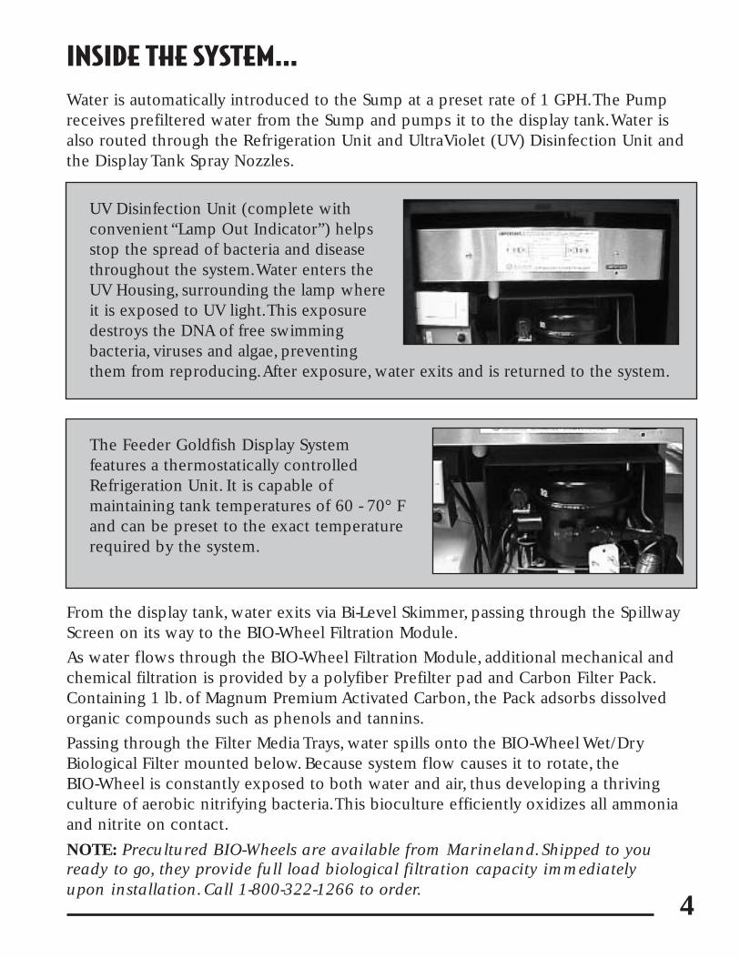
UV Disinfection Unit (complete with convenient “Lamp Out Indicator”) helpsstop the spread of bacteria and diseasethroughout the system.Water enters theUV Housing, surrounding the lamp whereit is exposed to UV light.This exposuredestroys the DNA of free swimming bacteria, viruses and algae, preventingthem from reproducing.After exposure, water exits and is returned to the system.
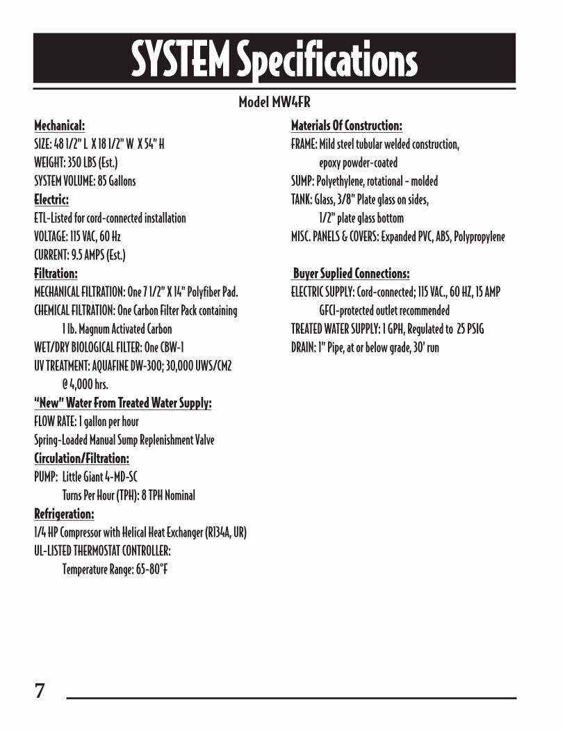
The Feeder Goldfish Display System features a thermostatically controlledRefrigeration Unit. It is capable of maintaining tank temperatures of 60 - 70° Fand can be preset to the exact temperaturerequired by the system.

5
Front, Rear and Side Access Panels
Provide easy access to Filtration Module, UV,Master Switch and all system outlets.
Sump Replenishment Valve
If water level in Sump drops below ideal operational level, Sump can be easily refilled using this simple spring loaded manual attachment.
Fish Feeding Timer
Allows you to shut down the Circulation Pump for feeding (factory set: 5 minutes) and thenautomatically restores the system to full operation after the preselected time has elapsed.
Display Tank Corner Spray Nozzles
Introduce water to the system, providing necessary surface and bottom agitation.
SPECIAL FEATURES

6
Custom Bi-Level Skimmer
Draws returning water and floating debris from both the bottom and surface levels to ensure uniform water processing.The specially designed Double Grid Spillway Screen protects fish from becoming drawn into Sump Chamber and it’s easily removable for cleaning.
7
Mechanical:SIZE: 48 1/2” L X 18 1/2” W X 54” HWEIGHT: 350 LBS (Est.)SYSTEM VOLUME: 85 GallonsElectric:ETL-Listed for cord-connected installationVOLTAGE: 115 VAC, 60 HzCURRENT: 9.5 AMPS (Est.)Filtration:MECHANICAL FILTRATION: One 7 1/2” X 14” Polyfiber Pad.CHEMICAL FILTRATION: One Carbon Filter Pack containing
1 lb. Magnum Activated Carbon WET/DRY BIOLOGICAL FILTER: One CBW-1 UV TREATMENT: AQUAFINE DW-300; 30,000 UWS/CM2
@ 4,000 hrs.“New” Water From Treated Water Supply:FLOW RATE: 1 gallon per hourSpring-Loaded Manual Sump Replenishment ValveCirculation/Filtration:PUMP: Little Giant 4-MD-SC
Turns Per Hour (TPH): 8 TPH NominalRefrigeration:1/4 HP Compressor with Helical Heat Exchanger (R134A, UR)UL-LISTED THERMOSTAT CONTROLLER:
Temperature Range: 65-80°F
Materials Of Construction:FRAME: Mild steel tubular welded construction,
epoxy powder-coatedSUMP: Polyethylene, rotational - moldedTANK: Glass, 3/8” Plate glass on sides,
1/2” plate glass bottomMISC. PANELS & COVERS: Expanded PVC, ABS, Polypropylene
Buyer Suplied Connections: ELECTRIC SUPPLY: Cord-connected; 115 VAC., 60 HZ, 15 AMP
GFCI-protected outlet recommendedTREATED WATER SUPPLY: 1 GPH, Regulated to 25 PSIGDRAIN: 1” Pipe, at or below grade, 30’ run
SYSTEM SpecificationsModel MW4FR

8
Exploded View w/ BIO-Wheel Goldfish Warehousing System
BIO-Wheel Filtration Module Exploded View
��������������������������������������������������������������������������������������������������������������������������������������������������������������������������������������������������������
yyyyyyyyyyyyyyyyyyyyyyyyyyyyyyyyyyyyyyyyyyyyyyyyyyyyyyyyyyyyyyyyyyyyyyyyyyyyyyyyyyyyyyyyyyyyyyyyyyyyyyyyyyyyyyyyyyyyyyyyyyyyyyyyyyyyyyyyyyyyyyyyyyyyyyyyyyyyyyyyyyyyyyyyyyyyyyyyyyyyyyyyyyyyyyyyyyyyyyyy��������������������������������������������������������������������������������������������������������������������������������������������������������������������������������������������������������
yyyyyyyyyyyyyyyyyyyyyyyyyyyyyyyyyyyyyyyyyyyyyyyyyyyyyyyyyyyyyyyyyyyyyyyyyyyyyyyyyyyyyyyyyyyyyyyyyyyyyyyyyyyyyyyyyyyyyyyyyyyyyyyyyyyyyyyyyyyyyyyyyyyyyyyyyyyyyyyyyyyyyyyyyyyyyyyyyyyyyyyyyyyyyyyyyyyyyyyy
������yyyyyy
Distribution Pipe
BIO-Wheel Assembly Cover
Prefilter Pad
Upper Filter Media Tray
Upper BIO-Wheel Housing
BIO-Wheel
Lower BIO-Wheel Housing
Fish Feeding Timer
Drip Emitter
To Outside Water SupplyCirculation Pump
Sump
Sump Replacement Valve
Carbon Prefilter Pack
Lower Filter Media Tray
Hinged Glass Top
Corner Spray Nozzles
UV Disinfection Unit
Master Switch
Thermostat
Front Electrical Access Panel
Side FiltrationAccess Panel
OverflowWeir
Bi-LevelSkimmer
Refrigeration Unit
Front FiltrationAccess PanelBIO-Wheel
Module
Display Tank

9
ADDING FILTRATION MEDIA
Prior to system startup, it is necessary to install filtration media. Follow the feweasy steps outlined below to get your system ready for operation. System shouldbe allowed to operate with only mechanical and chemical filtration media (blue polyfiber Prefilter Pad and carbon Filter Pack) - no BIO-Wheel - for a periodof 24 hours.
1. Remove Front Filtration Access Panel
2. Disconnect Distribution Pipe.
3. Remove clear BIO-Wheel Assembly Cover.
4. Lift out Upper Filter Media Tray and set aside.

5. Place Carbon Filter Pack inside Lower FilterMedia Tray (A).
NOTE: Before installing, be sure to rinseCarbon Filter Pack thoroughly in cold water (at sink) until water runs clear (B).
6. Replace Upper Filter Media Tray (C) and place polyfiber Prefilter Pad inside (D).
After 24 hours of system operation: A. Follow steps 1-4 above.
B. Remove Upper BIO-Wheel Housing and install BIO-Wheel in Lower BIO-Wheel Housing (A).Tray guides will ensure correct positioning. Replace Upper Housing (B).
C. Follow steps 6-7 above.
A
B
C D
B
A
7. Replace clear BIO-Wheel Assembly Cover. Reconnect Distribution Pipe.Replace Front Filtration Access Panel.
10
11
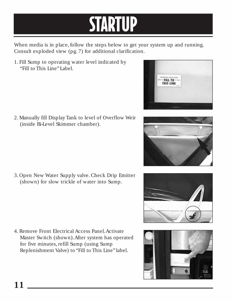
1. Fill Sump to operating water level indicated by “Fill to This Line” Label.
2. Manually fill Display Tank to level of Overflow Weir(inside Bi-Level Skimmer chamber).
3. Open New Water Supply valve. Check Drip Emitter(shown) for slow trickle of water into Sump.
4. Remove Front Electrical Access Panel.Activate Master Switch (shown).After system has operatedfor five minutes, refill Sump (using SumpReplenishment Valve) to “Fill to This Line” label.
STARTUPWhen media is in place, follow the steps below to get your system up and running.Consult exploded view (pg. 7) for additional clarification.

12
5. Adjust Thermostat to desired temperature. Checktemperature after approximately 8 hours and makeany necessary adjustments.
6. Allow system to operate with mechanical and chemical filtration media (blue polyfiber PrefilterPad and Carbon Filter Pack) for a period of 24hours. Be sure to inspect areas near pump, UV and other components for leaks.
NOTE: Remember not to install BIO-Wheel for first 24 hours of operation. See “Adding FiltrationMedia”, steps A-C (pg. 9).
7. Adjust “IN”Water Nozzles in Display Tank to ensureoptimum circulation.
NOTE: Adjust one nozzle to direct flow just belowsurface.Adjust other nozzle to direct flow towardbottom of Display Tank.
13
MAINTENANCETo ensure optimum operational efficiency, routine maintenance must be performed.The procedures listed below are neither difficult nor time consuming.Failure to follow these simple maintenance steps will adversely affect system performance and could lead to premature failure of some components.We recommend setting up a maintenance log to track procedure completion.
DAILY
Clean or replace Prefilter PadClogged filter pads overflow and will not collect waste. Uncollected waste is returnedto the aquarium and can severely reduce system efficiency.
To replace a Prefilter Pad:
1. Remove clear BIO-Wheel Filtration Module Cover.
NOTE: Have a bucket or large plastic pan ready to catch spills from removed pad(s).
2. Lift out used pad.
3. Rinse or replace with new pad (“blue” - #MZ0180 - for normal load conditions“white” - #MZ0181 - for heavily loaded systems).
NOTE: Pads may be rinsed more than once. Replace when they become damaged or misshapen from repeated use.
4. Replace Cover.
Clean Bi-Level SkimmerWipe Skimmer areas clean with designated tank cloth or scrubber.

14
WEEKLY
Replace Carbon Filter Pack Keeping the Prefilter Pad and Carbon Filter Pack clean and unrestricted is critical tothe successful operation of the BIO-Wheel. It must receive clean, filtered water tokeep nitrifying bacteria healthy and thriving.
1. Remove clear BIO-Wheel Filtration Module Cover.
2. Lift out Upper Filter Media Tray with Prefilter Pad.
NOTE: Have bucket or large plastic pan ready to catch water spillage from upper and lower tray.
3. Set Upper Filter Tray aside. Lift out Lower Filter Media Tray.
4. Rinse out Filter Tray. Replace Carbon Filter Pack (#MZ0175).
NOTE: Before installing, be sure to rinse Carbon Filter Pack thoroughly in cold water until water runs clear.
Check Water Pump and BIO-Wheel OperationObserve flow of water to the BIO-Wheel Assembly. Make sure that water flow to theBIO-Wheel is unhindered.The BIO-Wheel should rotate freely and remain wet at alltimes. Speed of rotation is not important. If a BIO-Wheel is turning - regardless of therate - it is working.
If flow interruption is evident, check Pump Inlet (in Sump) for obstructions. Ifclogged, shut off system, remove Strainer and clean. If flow interruption is still evident and no obstructions are found, consult “Troubleshooting Guidelines” section in this manual.
NOTE: A properly cultured BIO-Wheel is brown or discolored.There is no reason to clean a BIO-Wheel or replace it - unless it is damaged. If removed from the system for any reason, make sure that it is kept moist and exposed to air until you reinstall it. If a BIO-Wheel is allowed to dry out or is inadvertantly exposed to a contaminant, the bioculture may be destroyed.A precultured replacement can bepurchased directly from Marineland (see page 3).
Check UV “Lamp Out” Indicator LightThe “Lamp Out” Indicator Light is located on the UV Disinfection Unit Cover.When lit, it indicates that the UV Lamp is not operating. See “Service” section (pg. 16) for replacement instructions.

15
Wipe Down All Exterior Surfaces Never use chemicals, soaps, detergents or harsh abrasives on any part of the system.Do not use cleaners inside or near the tank at any time.
WARNING: Never spray insecticides within 20 feet of your tank system.Theresulting contamination could kill your fish and destroy your biological filter.If you must use insecticides, be careful to turn off the system and cover allopen water until the odor has cleared from the area completely.And don’t forget to turn the system back on.
AT LEAST EVERY 2 WEEKS
Inspect Display Tank Inlets Remove or wipe away any obstructions or algae growth to ensure unhindered flow.
Clean All Gravel Regular cleaning of all gravel and tank bottoms removes excess debris and keeps tankclear and sparkling.
Inspect Display Tank For Algae Growth Algae spores enter the system naturally via tank inhabitants and light allows them togrow. Although your system’s UV Disinfection Unit eliminates the majority of algaespores, the more light you have, the greater the potential for some algae growth.Toremove algae, simply wipe inside tank surface with a cloth, algae scraper or blue filterpad. NEVER use soap or metal scouring pads. Maintain a separate cloth only for thetank. It should be kept clean and isolated from other departments so that it does notget contaminated by multiple task use.
16
MONTHLY
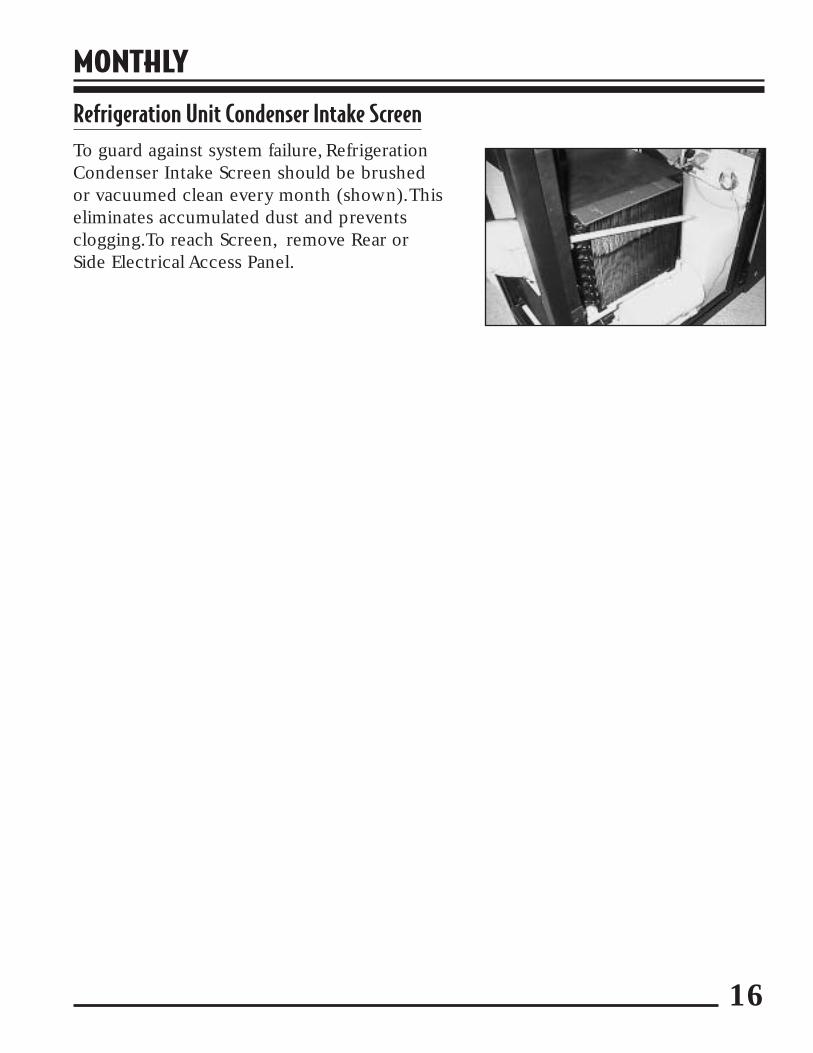
Refrigeration Unit Condenser Intake ScreenTo guard against system failure, RefrigerationCondenser Intake Screen should be brushed or vacuumed clean every month (shown).This eliminates accumulated dust and prevents clogging.To reach Screen, remove Rear or Side Electrical Access Panel.

17
Aquafine UV Disinfection UnitIMPORTANT NOTE: To prolong the life of the AQUAFINE UV Disinfection Unit and avoid leaving fingerprints on the UV Lamp, we strongly recommend that youwear cotton gloves at all times during servicing of UV Sterilizer Unit.
For convenient Quartz Sleeve servicing, we recommend the MaRS UV SterilizerServicing Kit (MZ0017). Specifically assembled for this purpose, each kit contains a pair of cotton gloves, silicon lubricant and detailed instructions. UV Lamps arealso available (MZ0190).To order call 1-800-322-1266.
SERVICE
Spring
Flow Inlet
UV Lamp
Treatment Chamber
Flow Outlet
Compression Nut
SocketCap
RubberLamp Socket
Quartz Sleeve Quartz Sleeve
O-Ring
WARNING: Never look directly into UV Lamp while in operation…eye injury may occur.
Never restore power while UV Lamp is separated from Treatment Chamber. Skindamage and/or injury may result.
Always make sure hands are absolutely dry before servicing equipment.
Power Cord
O-Ring
Compression Nut
We strongly recommend that all servicing for your system be performed by a qualified technician or trained associate. For a service referral, call
1-800-322-1266.

18
EVERY SIX MONTHS
UV Disinfection Unit and Quartz Sleeve (Exploded Diagram, pg. 16)
The UV Lamp has a useful service life of about 6 months.After this time – whether itcontinues to appear functional or not – it must be replaced. If the “Lamp Out”Indicator Light goes on before this time, change lamp immediately.
The Quartz Sleeve will develop a layer of scum on its surface which can reduce UVLamp effectiveness. Scum should be cleaned off at least once every six months.Whenchanging UV Lamp, always clean Quartz Sleeve. Always exercise care when cleaning.
1. Turn off Master Switch.Allow UV unit to drain (3-5 minutes).
2. Open Front and Side Electrical Access Panels.Remove UV Cover by unscrewing outer nuts and lifting away from unit.
3. Unscrew both threaded Socket Caps from TreatmentChamber ends. Gently disconnect UV Lamp fromRubber Lamp Sockets and carefully remove UV Lampfrom Treatment Chamber, sliding it out through SideElectrical Access Port (as shown). Carefully set aside.
4. Unscrew and remove both threaded Compression Nuts. Grasp one end of QuartzSleeve and gently draw it from Treatment Chamber.
Caution: Quartz Sleeves are very fragile. Handle with care to prevent breakingor chipping.
5.Wash Quartz Sleeve with mild soap and hot water. Rinse thoroughly with hot water.NOTE: For heavier deposits, we recommend cleaning with calcium/lime remover oralcohol. Gently wipe sleeve with clean cloth before reinstalling.
6.Working from one end of Treatment Chamber, carefully insert clean Quartz Sleevethrough stainless steel nipple and into Treatment Chamber. Sleeve should protrudean equal distance from each end.

19
7. Before installing Compression Nuts, remove and clean O-Rings. Then lubricate eachwith a very thin coating of silicon lubricant (provided). Reinstall O-Rings.
NOTE: O-Rings should be replaced each year.8. Install Compression Nut at one end. Finger tighten while holding opposite end
of Quartz Sleeve.
9. Install remaining Compression Nut. Hand tighten (firmly) both Compression Nuts. CAUTION: Do not over tighten Compression Nuts.This can fracture ends of Quartz Sleeve.After hand tightening Compression Nut, release it one half turn to avoid fracture.
10. Carefully reinsert UV Lamp into open Quartz Sleeve and gently push it about 2-3 inches out beyond the opposite Compression Nut.
11. Insert lamp base into spring equipped Rubber Lamp Socket (see diagram),sliding “boot” portion over end of lamp. Push until you feel a firm,“bottomed out”connection.
NOTE: Make sure “boot” does not fold under.
12. Connect opposite lamp base to remaining Rubber Lamp Socket.
13. Once Rubber Lamp Sockets are attached to UV Lamp at both ends, position Rubber Lamp Sockets inside Socket Caps. Making sure that Rubber Lamp Socketsare seated securely, join Socket Caps to threaded ends of Compression Nuts andfinger tighten.
14. Replace UV Cover.
15.Turn on Master Switch. Inspect unit for leaks. Replace Electrical Access Panels.

20
For a service referral, call the 24-Hour MaRS Hotline at:
1-800-576-MaRS (6277).
If entire system abruptly shuts down…• Reset circuit breaker.
• Make sure Master Switch is turned on.
• Check Pump Inlet Strainer in Sump for obstructions.
If water turns yellow or odors develop…• Replace Carbon Filter Pack.
If a BIO-Wheel fails to rotate…• Inspect Prefilter Pad and Carbon Filter Pack for clogging. Clean or change
as needed.
• See if BIO-Wheel is obstructed. Clean bearings, check for unimpeded rotation and reinstall.
• Make sure that Sump is not overfilled. Check Return Tube for obstruction.
• Check Pump Inlet Strainer in Sump for obstructions.
If water flow to BIO-Wheels or display tanks stops or flow is sluggish…• Inspect Pump Inlet Strainer in Sump. Clean and/or remove any debris
or obstructions.
• Remove Front Electrical Access Panel and make sure System Pump is plugged in, motor fan is turning.
• Call for service if problem persists.
If water temperature is too low or too high…• Check Thermostat setting.
NOTE: Thermostat reading may differ from measured Display Tank temperature…adjust thermostat as required and monitor Display Tank temperature with thermometer, allowing 3-4 hours for temperature to stabilize before checking again.
• Make sure power cord to Refrigeration Unit is plugged into proper outlet.
• Call for service if Thermostat or Refrigeration Unit is malfunctioning.
TROUBLESHOOTING GUIDELINES
21
If large amounts of air bubbles are evident in display tanks…• Check water level in Sump. If below desired level, add water via Replenishment
Valve and check frequently.
• Make sure Pump Inlet Strainer is fitted firmly in place.
• Call for service if problem persists.
If Drip Emitter or Sump Replenishment Valve flow is greatly reduced or stopped...• Check water level in Sump.
• Call for service if problem persists.
IF U.V. Lamp goes out (Lamp Out Indicator is lit)...• Remove Front Access Electrical Panel and confirm that and UV power cord is
plugged into appropriate outlet.
• Replace UV Lamp (see instructions, pg 18 & 19). If problem persists after Lamp is replaced, call the MaRS 24 Hour Hotline for replacement part and/or further assistance.
IF water is leaking from UV Lamp Housing...• Reinstall Quartz Sleeve according to directions.

A Division of AQUARIA, Inc. • Moorpark, CA 93021© 1997 AQUARIA, Inc. Printed in the U.S.A. Item# Z090527A 12/97
CUSTOMER SERVICE
Marineland, BIO-Wheel, MaRS and Magnum are trademarks of AQUARIA, Inc.
Should you experience problems with your system, call the 24-Hour MaRS Hotline at 1-800-576-MaRS (6277).
To order any of the items listed below, call:1-800-322-1266
WEEKLY USE ITEMS:1. Prefilter Pads – Blue MZ01802. Prefilter Pads - Coarse White MZ01813. Carbon Filter Packs MZ0175
SERVIC ING ITEMS:1. Maintenance Kit MZ00122. Tank Isolation Kit MZ00203. KX Carbon/Micron Repl. Kit MZ00404. UV Sterilizer Servicing Kit MZ00175. UV Lamp MZ01906. Replacement O-Rings MZ0041