federal motor vehicle safety standard #111€¦ · federal motor vehicle safety standard ... front...
TRANSCRIPT

1
Federal Motor Vehicle Safety Standard #111

2
Federal Motor Vehicle Safety Standard
§571.111 Standard No. 111; Rearview Mirrors
S1. Scope. This standard specifies requirements for the performance and location of rearview mirrors.
S2. Purpose. The purpose of this standard is to reduce the number of deaths and injuries that occur when the driver of a motor vehicle does not have a clear and reasonably unobstructed view to the rear.
S3. Application. This standard applies to passenger cars, multipurpose passenger vehicles, trucks, buses, school buses and motorcycles.
FMVSS #111

3
Sections of Safety Standard FMVSS #111
S4. Mirror Definitions.Convex mirror means a mirror having a curved reflective surface whose shape is the same as that of the exterior surface of a section of a sphere.
Effective mirror surface means the portions of a mirror that reflect images, excluding the mirror rim or mounting brackets.
Unit magnification mirror means a plane or flat mirror with a reflective surface through which the angular height and width of the image of an object is equal to the angular height and width of the object when viewed directly at the same distance except for flaws that do not exceed normal manufacturing tolerances. For the purposes of this regulation a prismatic day-night adjustment rearview mirror one of whose positions provides unit magnification is considered a unit magnification mirror.
S5. Requirements for passenger cars.
S5.1 Inside rearview mirror. Each passenger car shall have an inside rearview mirror of unit magnification.

4
S5.1.1 Field of view.
Except as provided in S5.3, the mirror shall provide a field of view with an included horizontal angle measured from the projected eye point of at least 20 degrees, and a sufficient vertical angle to provide a view of a level road surface extending to the horizon beginning at a point not greater than 61 m to the rear of the vehicle when the vehicle is occupied by the driver and four passengers or the designated occupant capacity, if less, based on an average occupant weight of 68 kg. The line of sight may be partially obscured by seated occupants or by head restraints. The location of the driver's eye reference points shall be those established in Motor Vehicle Safety Standard No. 104 (§571.104) or a nominal location appropriate for any 95th percentile male driver
S5.1.2 Mounting. The mirror mounting shall provide a stable support for the mirror, and shall provide for mirror adjustment by tilting in both the horizontal and vertical directions. If the mirror is in the head impact area, the mounting shall deflect, collapse or break away without leaving sharp edges when the reflective surface of the mirror is subjected to a force of 400 N in any forward direction that is not more than 45° from the forward longitudinal direction.

5
S6 Requirements for multipurpose passenger vehicles, trucks, and buses, other than school buses, with GVWR of 4,536 kg or less.
S6.1 Each multipurpose passenger vehicle, truck and bus, other than a school bus, with a GVWR of 4,536 kg or less shall have either—(a) Mirrors that conform to the requirements of S5.; or (b) Outside mirrors of unit magnification, each with not less than 126 cm2 of reflective surface, installed with stable supports on both sides of the vehicle, located so as to provide the driver a view to the rear along both sides of the vehicle, and adjustable in both the horizontal and vertical directions to view the rearward scene.
S7. GVWR of more than 4,536 kg and less than 11,340 kg and buses,
other than school buses, with a GVWR of more than 4,536 kg.
S7.1 Each multipurpose passenger vehicle and truck with a GVWR of more than 4,536 kg and less than 11,340 kg and each bus, other than a school bus, with a GVWR of more than 4,536 kg shall have outside mirrors of unit magnification, each with not less than 323 cm2 of reflective surface, installed with stable supports on both sides of the vehicle. The mirrors shall be located so as to provide the driver a view to the rear along both sides of the vehicle and shall be adjustable both in the horizontal and vertical directions to view the rearward scene.

6
S8. GVWR of 11,340 kg or more.
S8.1 Each multipurpose passenger vehicle and truck with a GVWR of 11,340 kg or more shall have outside mirrors of unit magnification, each with not less than 323 cm2 of reflective surface, installed with stable supports on both sides of the vehicle. The mirrors shall be located so as to provide the driver a view to the rear along both sides of the vehicle and shall be adjustable both in the horizontal and vertical directions to view the rearward scene.
7
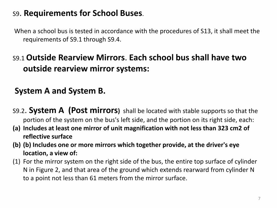
S9. Requirements for School Buses.
When a school bus is tested in accordance with the procedures of S13, it shall meet the requirements of S9.1 through S9.4.
S9.1 Outside Rearview Mirrors. Each school bus shall have two outside rearview mirror systems:
System A and System B.
S9.2. System A (Post mirrors) shall be located with stable supports so that the portion of the system on the bus's left side, and the portion on its right side, each:
(a) Includes at least one mirror of unit magnification with not less than 323 cm2 of reflective surface
(b) (b) Includes one or more mirrors which together provide, at the driver's eye location, a view of:
(1) For the mirror system on the right side of the bus, the entire top surface of cylinder N in Figure 2, and that area of the ground which extends rearward from cylinder N to a point not less than 61 meters from the mirror surface.

8
Federal Motor Vehicle Safety
Standard # 111
9
How to Comply With FMVSS # 111
Place 16 markers around the bus. There will be 2 additional markers placed 200 ft. behind the bus.
These markers should be visible either through real vision and/or reflective vision, both working
together.

10
FMVSS #111 Marker
Placement

11
9 Markers in Front of Bus and1 Marker at Each Front Wheel

12
5 Markers at Rear Wheels and2 Markers at 200 Ft.

13
Gwinnett County Mirror Grid System 14 cones strapped together on 5 grids(2 more cones
stand alone), laid out per FMVSS 111

14
Mirror Grid Set Up
Nine cones in front of bus Two single cones either side of front tires
15
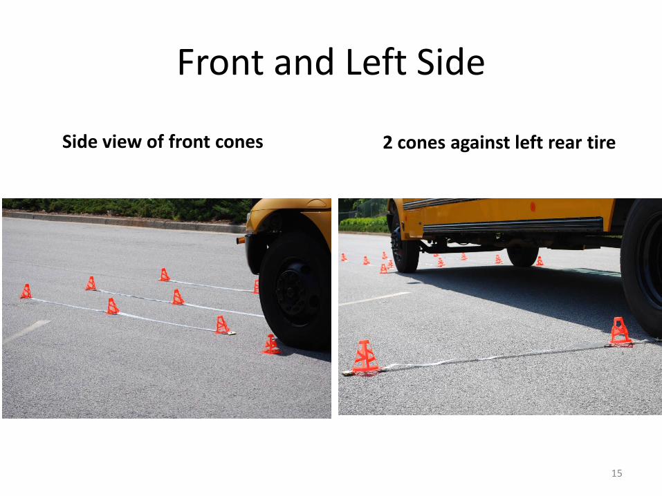
Front and Left Side
Side view of front cones 2 cones against left rear tire

16
Right Side Rear Cones
Three cones right side Must see 12 ft. door side, students exit to safety

17
Left Side Rear ConesHinge stop up against the
bottom of left rear tireFirst Cone 1 ft. from Rear tire
second cone at 6 ft.

18
Right Rear Cones
Cones at 1 - 6 - 12 ft.Right rear hinge stop at bottom of right rear tire
19
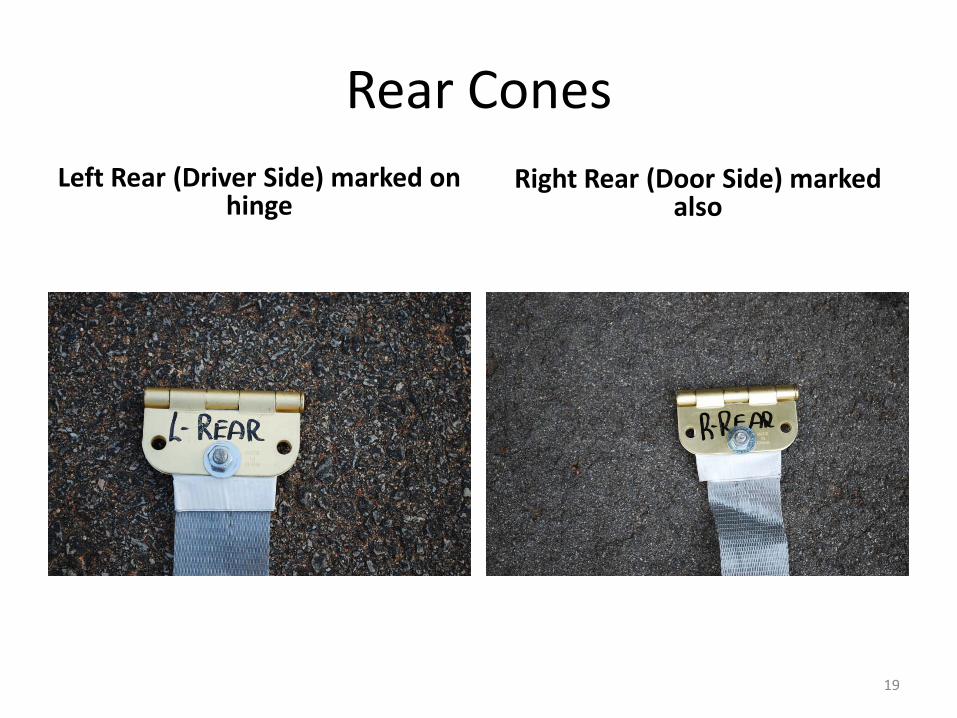
Rear ConesRight Rear (Door Side) marked
alsoLeft Rear (Driver Side) marked on
hinge
20
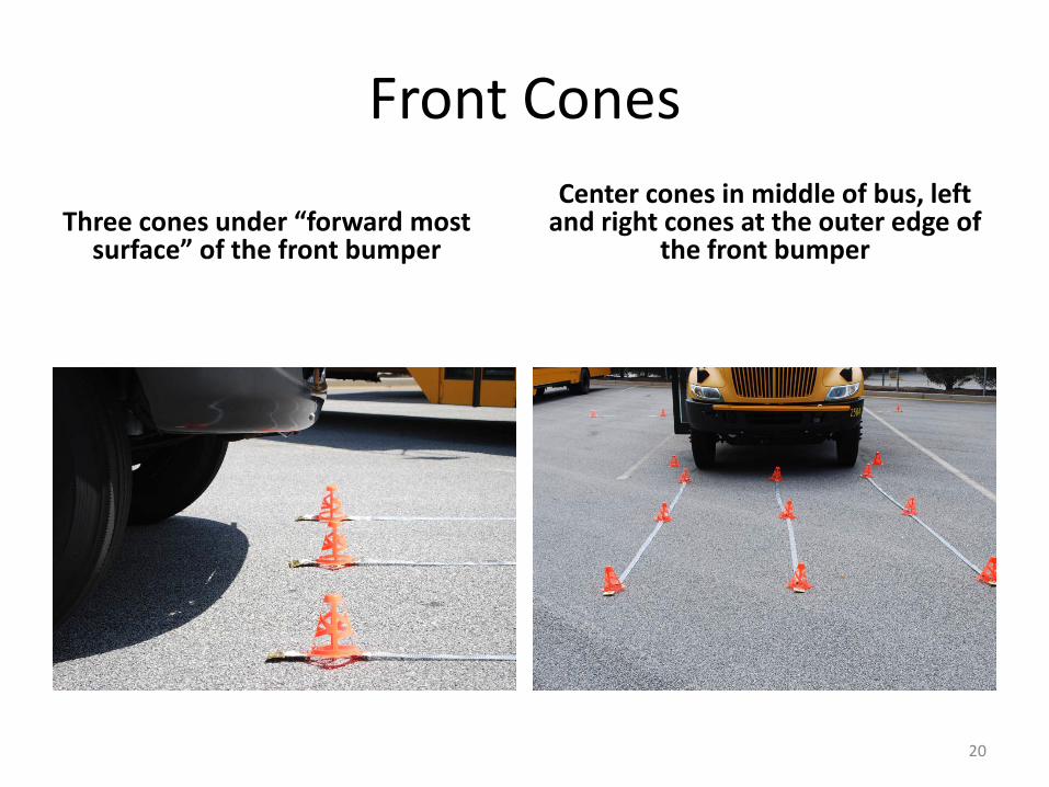
Front Cones
Three cones under “forward most surface” of the front bumper
Center cones in middle of bus, left and right cones at the outer edge of
the front bumper

21
Front Cones
Center cones 6 ft. out Outer cones 12 ft. out

Front Wheel Cones
Approx. 1 ft. out from tire
22

23
16 Cone Layout
Right Side View Left Side View
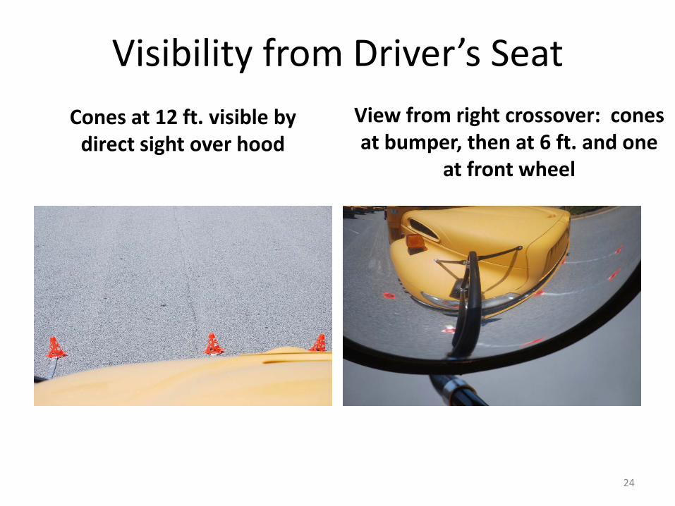
Visibility from Driver’s SeatCones at 12 ft. visible by
direct sight over hoodView from right crossover: cones at bumper, then at 6 ft. and one
at front wheel
24

25
From Driver’s SeatRight front crossover Left front: 6 cones plus 1 cone
at front wheel

26
Crossovers.
These photos were taken from outside of the bus to give a clearer picture of the cones.

27
Right side: Cones 1 – 6 – 12 ft
Post Mirrors From Driver’s Seat
Left side: Cones at 1 and 6 ft.

28
Visibility From Driver’s Seat
Cone at back of bus and student at 200 ft.
Cones at 1 – 6 – 12 ft. door side

29
Other ViewsView of crossover mirror
outside of busInterior mirror set so rear door padding is just visible in top of
mirror

30
FMVSS #111 Vision Grid
Includes dimensions between cones and instructions to drivers describing which mirror they must be using to view all 16 cones.
If all the mirrors are set correctly, driver will be able to view 200 Ft to the rear through the post mirrors and interior student mirror.

31
Right Side
Can you see the front wheel cone in your right crossover?
Can you see the 3 cones against your rear tire, door side?

32
Left SideSame for left crossover Only 2 cones against left rear
tire, driver’s side

33
Constructing Mirror Grids Marking Template
12 ft. long 2x4 template, drilled to line up with cone base mounting holes
Line up the center of the front cone to the front end of the template, and clamp it

34
Mark template through the back hole of the front cone as shown Drill ¼ inch hole about ¼ inch deep
Marking and Drilling Template

35
Measure 6 ft. along template and draw a center line
Place cone top over center line, mark and drill holes as shown
Marking and Drilling for Middle Cone

Marking and Drilling for Rear ConeStarting Assembly
Place top of rear cone over end of template, mark and drill
hole
Pull strapping over front of template, wrap two widths of
duct tape around end
36

37
Building Front Grid
Clamp hinge over end, pierce a hole through tape and strap
Insert ¼ x ¾ bolt, 2 washers either side of hinge and nut.
38
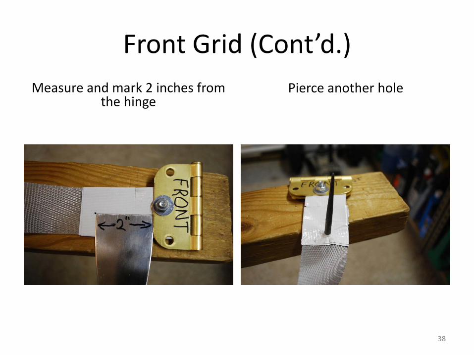
Front Grid (Cont’d.)Measure and mark 2 inches from
the hingePierce another hole

39
Front Cone
Insert bolt, cone, washers and nut Mark strap at second holethrough cone
40
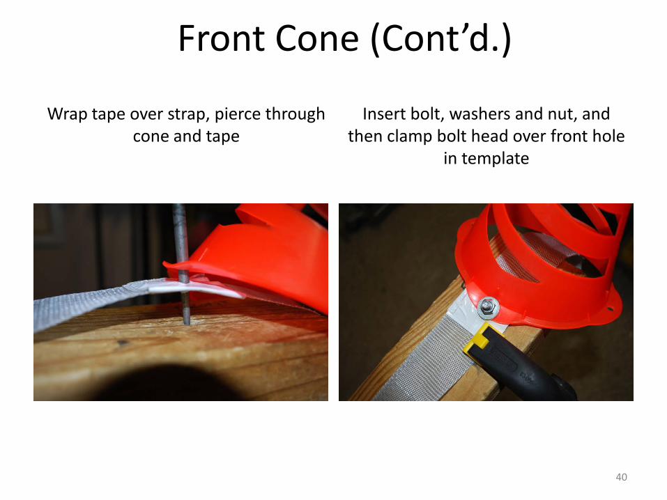
Front Cone (Cont’d.)
Wrap tape over strap, pierce through cone and tape
Insert bolt, washers and nut, and then clamp bolt head over front hole
in template

41
Center ConeWrap tape over strap in line with
center cone holesPierce tape and strap into
template holes

42
Center Cone (Cont’d.)
Insert bolts and washers Mount center cone over bolts add washers and nuts

43
Rear Cone
Line up tape with the front hole Punch hole through it and strap into template

44
Rear Cone (Cont’d.)
Insert bolt and washer Mount rear cone

45
Rear Cone (Cont’d.)
Stretch strap under cone, leave about 1 inch overhang and cut it
Wrap the end with tape

46
Rear Cone(Final Step of Front Grid)
Clamp hinge over cone and tape. Pierce through center hole in hinge
Insert bolt washers and nut
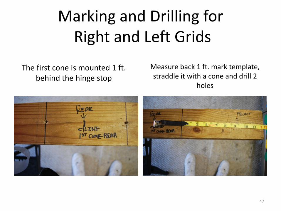
47
The first cone is mounted 1 ft. behind the hinge stop
Measure back 1 ft. mark template, straddle it with a cone and drill 2
holes
Marking and Drilling forRight and Left Grids

48
Building Right And Left Grids
Tape around strap, in line with template holes, pierce holes into template
Wrap tape around strap, mount hinge, pierce hole, install bolt, washer and nut

49
Rear Grids Front ConeInsert bolts through tape and
strapMount cone, clamp hinge on top
of and at end of template

50
Right Rear Grid (Cont’d.)Install center cone the same as
front gridInstall rear cone the same as
front grid

51
Left Rear GridConstruct the same as right rear grid,
just stop at center cone.Stop at 6 ft (center cone) and install
hinge

To Stack Grid
52
• If you want to stack the grids, cut and remove the tape
between the bolts

53
7/16 inch socket & wrench, clamps, scissors, AWL (piercing tool ),cup of soapy water
Tighten all bolts using a power tool if available
Final AssemblyTools Needed

54
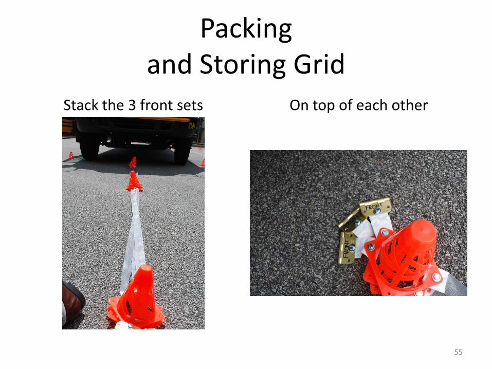
55
Stack the 3 front sets On top of each other
Packing and Storing Grid

56
Stack the rear 2 sets 6 ft. on top of 12 ft.
Packingand Storing

57
Stack into two groups Put in box leave strapping overlapping sides
Packing Into Box

58
Fold over strapping on top of cones to reduce creasing
Closing Box“Field of Vision” Mirror grid
diagram taped to lid

59
David Hart –Gwinnett County Pubic Schools
Charlene Majors – Gwinnett County Public Schools
Mirror Lite Safety Cross AwardMirror Grid System - Designed and Developed by