features specifications - senju m · nrf series features specifications successful development of...
TRANSCRIPT
TaiSemi14-01E
A superactive low-volatile/high heat-resistant water-soluble flux for ball soldering
WF6317
Features
Specifications
● Low viscosity and high tacking power stabilize ball holding force and ensures excellent solder wettability● Easy to wash out water-soluble �ux which can be used for Pb-free re�ow soldering at 250˚C● Prevents and inhibits contamination of re�ow ovens with low-volatile �ux
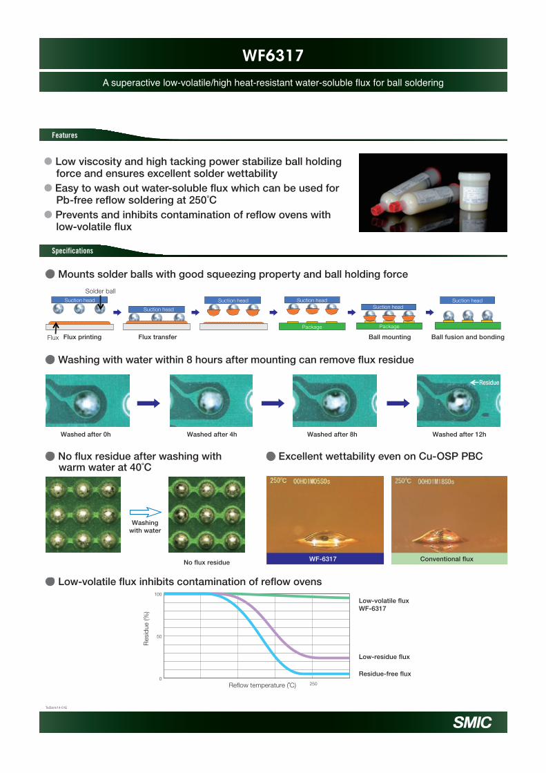
● Mounts solder balls with good squeezing property and ball holding force
● No �ux residue after washing with warm water at 40˚C
● Low-volatile �ux inhibits contamination of re�ow ovens
Solder ball
Flux printing Flux transfer Ball mounting Ball fusion and bondingFlux
Suction head
Suction head
Suction headSuction head
Package
Suction head
Package
Suction head
● Washing with water within 8 hours after mounting can remove �ux residue
Washed after 0h Washed after 4h Washed after 8h Washed after 12h
Residue
Washingwith water
No flux residue
● Excellent wettability even on Cu-OSP PBC
WF-6317 Conventional flux
Res
idue
(%)
100
50
0250Reflow temperature (˚C)
Low-volatile fluxWF-6317
Low-residue flux
Residue-free flux

Flux residue reinforces solder joints
TaiSemi14-02E
Joint Protect Flux JPK8
Features
Specifications
● Flux residue improves joint strength by approx. 50%● Even without cleaning, volatile components do not suppress a good under�ll injection property● Flux residue prevents cracks during long-term temperature cycle tests
● Process example
● Maintains good adhesion with acid anhydride-based under�ll agents
● Flux residue reinforces joints and increases joint strength by approx. 50%
● Flux residue reinforces joints and prevents cracks
● Maintains a good under�ll injection property regardless of the transfer amount
● JPK8
Temperature cycle -40°C ↔ 125°C/after 1000 cycles
Flux film formation Dipping
JPK8 JPK8
Transfer
Mount Reflow
JPK8 residue
Underfill injection
Join by transfer and reflow and inject underfill without cleaningFlux residue reinforces joints, and a low amount of volatile components does not contaminate joints
Initial stage After 250 cycles After 500 cycles
Ball diameter: 0.3 mmTemperature cycle: -4.0°C /30 min. ↔ 125°C/30 min.Results of a temperature cycle test
Flux residue
Result of a JEDEC Level 3 moisture sensitivity test
JEDEC Level 3; 30℃/60%RH 196h
Comparison of joint strength after high temperature exposure
Result of a temperature cycle test
Transfer time : 50msec
Transfer time : 250msec
Transfer time : 1000msec
Small
Large
JPK8 Flux residueJPK8
Normal flux Cracks
JPK8Solder Ball
Before After
Storage time at 150°C (h)
Str
enb
th( N
)
0 1 2
6
5
4
3
2
1
0
Ball diameter : 0.3mm
Test speed : 30um/s
Test height : 15um
JPK8
Normal flux

JPCA14-03E
Realization of Highly Reliable Mounting with No-Residue / No-Cleaning
NRF SERIES
Features
Specifications
● Successful development of halogen-free �ux with no-residue
● Delivers excellent solder wettability under a rapid-heating pro�le
● Halogen-free and no-residue �ux keeps residue level at 1% or lower● Maintains excellent solder wettability under a rapid-heating pro�le● Highly compatible with under-�lling materials; leaves no void
The improved product offers even better wetting extendability than conventional product
● Highly compatible even with under-�lling materials; no formation of delamination or voids
100
80
60
40
20
0
-20
300
250
200
150
100
50
00 20 40 60 80 100 120
TG
[%]
Tem
p[d
egC
]
Time[sec]
TGA evaluation result Evaluation method
Evaluation results
Cross section picture
Under-filling
X-ray void check
Post re�ow solder ball with no �ux
Copper plate Copper plate
99% or more �ux
Rapid-heating
600µm
SAC305
NRF
1100µm
It’s measured 4 times per each bump,and they are averaged.
NRF-S13NRF-S14temp(degC)
Heating profile (TCB process)
Temp[degC]
300
250
200
150
100
50
00 20 40 60 80 100 120
Time[sec]
So
lder
sp
read
[um
]
Flux
1120
1100
1080
1060
1040Conventional
productNRF-S13 NRF-S14 NRF-S13
There is no delamination and void.Compatibility is good.
There is no void after flow UFalso after cure .
NRF-S14
Solder

Form 120µm-pitch bumps with Φ4μm alloy powder
LAS-M705/OZ63-BPS ser.
TaiSemi14-04E
Features
Specifications
● Excellent sticking characteristic forms �ne bumps in each process● Realizes excellent melting characteristic even when Type 7 or �ner powder● Good solder wettability enables bump formation with fewer voids
● Trend towards �ne pitch
● Pitch sizes and bump formation in various supplying methods
● Excellent �ux prevents heat sags and forms good bumps
● Even though �ne powder, still has good wettability and forms bumps with fewer voids
● Forms good bumps even when using paste with �ne powder because of excellent melting property
● Forms 120 µm pitch bumps with φ4µm alloy powder
Metal mask Type 7 (φ1 to 10 μm) Type 7 or �ner (φ1 to 6 μm)
120 µm pitch printing
Opening size
Solder
Narrower and thinner
Mask opening size
Conventionalproduct
Conventional product
Preheating
180˚C-3min
Preheating
180˚C-3min
BPSseries
BPS series
After printing Bump formation after re�ow
Uniquely developed �ux prevents oxidation
MovementRolling
Movement
Stencil Pressurization
RollingMovement
Dry �lm
Type 7 or �ner90 to 150 mm pitch
Type7110 to 180 mm pitch
Type6160 mm pitch or more
Dry �lm methodCartridge methodOpen squeegee method
TaiSemi14-05E
Void-free soldering with residue-free paste
M705-NRB70
Features
Specifications
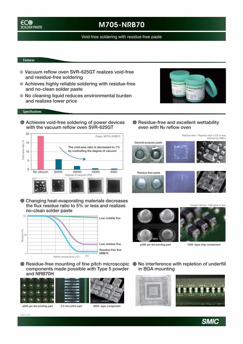
● Achieves void-free soldering of power devices with the vacuum re�ow oven SVR-625GT
● Changing heat-evaporating materials decreases the �ux residue ratio to 5% or less and realizes no-clean solder paste
● Residue-free and excellent wettability even with N2 re�ow oven
● Residue-free mounting of �ne pitch microscopic components made possible with Type 5 powder and NRB70H
● No interference with repletion of under�ll in BGA mounting
Degree of vacuum (Pa)
ø200 µm dot printing part 0.4 mm pitch part 0603 -type component
20
15
10
5
0No vacuum 30000 20000 10000 5000
Paste: M705-NRB70
Void
are
a ra
tio %
The void area ratio is decreased to 1% by controlling the degree of vacuum
Resi
due
(%)
100
50
0250Reflow temperature (℃)
Low-volatile flux
Low-residue flux
Residue-free fluxNRB70
Residue-free = Residue ratio is 5% or less(defined by SMIC)
General-purpose paste
Residue-free paste
Oxygen density: 1500 ppm or less
φ200 µm dot printing part 1005 -type chip component
● Vacuum re�ow oven SVR-625GT realizes void-free and residue-free soldering● Achieves highly reliable soldering with residue-free and no-clean solder paste● No cleaning liquid reduces environmental burden and realizes lower price

TaiSemi14-06E
Low-Ag/Ag-free solder pastes with lower void
LS720V Series
Features
Specifications
● Reduces voids by improving �uidity of �ux during solder melting● Reduces voids even in bottom surface electrode type components by improving solder wettability ● LS720V �ux which can be used for low-Ag/Ag-free alloys
● Main reason of void formation and the measure
● Comparison of crack progression between Sn-Cu-Ni-Ge and M773
● The effect of LS720V is observed in suppressing void formation
● Joint strength improved with the addition of Bi and Ni (compared to 0% Ag material)
● Effect of Ni addition
Although voids are tend to occur when bottom surface electrode type components such as QFN frequently, it can be reduced by LS720V
100% Crack progression Approximately only 30% crack progression
Replacing Cu with Ni makes the construction of the bonding surface �ner and thus increases strength
Cycle conditions: -40℃ to +125℃, after 1000 cycles
Surface treatment: Cu-OSP
Bottom surface electrode
Conventional product LS720V product
Appearance of QFN
Improvement
Without Ni
Reflow: 1time
Reflow: 4times
With Ni
PWB
QFN
SolderVoid
Conventional product LS720V Conventional product LS720V
4mm QFN 8mm QFN
50
40
30
20
10
0
Void
are
a ra
tio (%
)
● Development of Ag-free/M773 alloy
M705M40M47M773
Price
Lowerprices
2000 2010 2013
Achieves Ag-free while confrming reliability
Solder paste
M705
M40
M47
M773
3.0% Ag
1.0% Ag
0% Ag
0.3% AgSn-3.0Ag-0.5CuSn-1.0Ag-0.7Cu-1.6Bi-InSn-0.3Ag-0.7Cu-0.5Bi-NiSn-0.0Ag-0.7Cu-0.5Bi-Ni
Stre
ngth
(N)
Number of temperature cycle (Cycle)
M705;SAC305M773
Sn-Cu-Ni-Ge
M773;Sn-Cu-Bi-Ni80
70
60
50
40
30
20
0 200 400 600 800 1,000 1,200 1,400 1,600
-40℃/30min ⇔ +85℃/30minEvaluation using chip resistors
Sn-Cu-Ni-Ge M773
Voids are caused by reducing gas from residual �ux and poor solder wettability
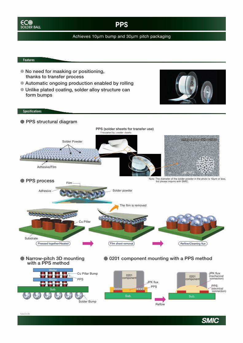
Achieves 10μm bump and 30μm pitch packaging
PPS
Features
Specifications
TaiSemi14-07E
● No need for masking or positioning, thanks to transfer process● Automatic ongoing production enabled by rolling ● Unlike plated coating, solder alloy structure can form bumps
● PPS structural diagram

Cu core ball facilitate 3D packaging and narrow-pitch mounting
Cu Core Ball
TaiSemi14-09E
Features
Specifications
● Ensures space to easily realize a highly-reliable component-built structure● Enables narrow-pitch mounting that can be performed through Cu pillar mounting using existing equipment● Promises high heat dissipation and electromigration countermeasures
● Ensures space through its multilayer structure with a Cu core
● Cu core ball facilitate 3D packaging
Cu ball
Solder plating
Cu ball
Ni plating
Solder plating
Cu core ball (spacer)
The Cu core ball ensure space to easily realize a highly-reliable component-built structure
Realizes good drop resistance Exhibits a temperature cycle equivalent to that of a conventional product
● Characteristics
● Enables narrow-pitch mounting without short circuit risk with existing equipment
● Drop test and temperature cycle test
PKG
PCBPCB
PKG
PCB
PKG
Solder ball
Cu core ball
Superior electromigration resistance
Temperature cycle test
Ensures appropriatespace
Inclination
Short
PCB
PKG
Cu has good thermal conductivity
PCB
PKG
PCB
PKG
Electromigration Ensures space Heat dissipation
Solder platingCu plating
Eliminates the plating processes required in Cu pillar mounting
Cu pillar mounting Cu core ball mounting
Cu core ball
Drop Number
Cum
ulat
ive
Freq
uenc
y
Drop testC-Cu M90M705 (conventional product )
C-Cu M90M705 (conventional product)
Cycle Number
Cum
ulat
ive
Freq
uenc
y
1
10
100
1 10 100 10001
10
100
1 10 100 1000

TaiSemi14-10E
A high-reliability WLCSP solder ball
M758
Features
Specifications
● Forms bumps with high joint strength on wafer electrodes
● Good wettability on copper plating such wafer electrodes
● Packaged M758 has excellent thermal fatigue resistance
● M758 forms bumps having high joint strength on wafer electrodes
● Good wettability on copper plating such wafer electrodes
● Packaged M758 shows good results in temperature cycle test
Failure mode5
4.5
4
3.5
3
2.5
2
1.5
1
0.5
0
SAC305 SAC405 M758
Shear height
CuPlating
Shear tool ShearFailure Mode Mode1
Pad Solder Solder & Interface Interface
Mode2 Mode3 Mode4
M758 forms bumps having high strength on the package level by the surface reforming effect of added Ni
The failure mode in every test is Mode 4: Interface failure
Stre
ngth
(N)
Shear Strength
1.3
1.2
1.1
1
0.9
0.8
SAC305 SAC405 M758M758 has good wettability for Cu plated package
M758 has excellent thermal fatigue resistance due to solid solution strengthening with Bi added compared to conventional products, such as SAC305 and SAC405.Also, M758 has drop impact resistance equivalent to or more than that of conventional products
Leng
th(m
m)
Spreadability test resultTesting method
Reflow oven(245℃) O₂;<200ppm
Flux
Cu plating
Measured location
Measuredlocation
99.9
10
1100 1,000 10,000 100 1,000 10,000
99.9
10
1
TCT Drop
Accu
mul
atio
n ra
te.%
Cycle number Drop number
Accu
mul
atio
n ra
te.%
ProductName Composition Melting
Point (%) Note
M705 SAC305 217-220 Pb-free Standard
M710 SAC405 217-229
M758 205-215 Suitable material for WLP
S/F : Cu WLCSP : Size 7 x 7mm

Simultaneously realizes high thermal fatigue resistance and drop impact reliability
M770
TaiSemi14-11E
Features
Specifications
● Material structures● Evaluation on Cu-OSP PCB
● Solves problems with contrary demands by means of technology controlling the separation strengthening and interface response● Excellent af�nity with all kinds of surface treatment materials (Cu, Ni, Au)● Optimized for mobile devices such as smart phones and in-vehicle ball packaging
● Material selection according to purpose and application
Interface Surface
Ni
Ni
M60
M61
Results from relative evaluation with M705 as basis.
Focus on thermal fatigue resistance: M60Focus on drop impact reliability : M61Satisfies both characteristics in a reliable manner: M770
M770
Ni
M60 M61 M770
Drop impact reliability
Thermal fatigue resistance
× ◎ ◎◎ × ○
● Evaluation on electrolytic Ni/Au plated PCB
99.9
10
11000 10000
Cum
ulat
ive
failu
re ra
te (%
)
Number of cycles (cycles)
Thermal fatigue resistance (electrolytic Ni/Au plated PCB)
M60
M61
M770
M705
99.9
10
110.10.01 10 100 1000
Cum
ulat
ive
failu
re ra
te (%
)
Number of drops (times)
Drop impact reliability (electrolytic Ni/Au plated PCB)
M61M770
M705
M60
99.9
10
11 10 100 1000
Cum
ulat
ive
failu
re ra
te (%
)
Number of drops (times)
Drop impact reliability (Cu-OSP PCB)
M60 M61M770M705
99.9
10
11000 10000
Cum
ulat
ive
failu
re ra
te (%
)
Number of cycles (cycles)
Thermal fatigue resistance (Cu-OSP PCB)
M60
M61
M770
M705

TaiSemi14-12E
M61 solder ball with high drop impact resistance
M61
Features
Specifications
For products with high risk of being dropped, such as mobile devices● Solder balls with excellent drop impact resistance● Accommodates �ne pitch connections, high density connections, and high-quality packaging● Accommodates every type of surface treatment material
● Composition
● Concentration of stress is avoided through property modi�cation of the joint interface by adding elements and optimizing the amount to be added.
● Drop test result
● Fracture surface observation
● Aims to achieve the stress absorption effect of bulk solder through material softening
µ
µ
Productname Alloy composition
Meltingtemperature(℃)
Solid phase Liquid phase
The diffusion layer has been made thin,fine and smooth by adding Ni.
Cum
ulat
ive
failu
re In
In (1
/[1-F
(t)])
Ag content : %
Sn-3.0AgSn-1.0Ag
2.3%
Eutectic phase (Ag3Sn Cu6Sn5 compound)Vickers hardness (0.49 N/30 sec)
Hard
Soft
20
17.5
15
12.5
10
7.5
50 1 2 3 4 5
Sn phase
Strength
Ag concentrationLow High
M61
M705
M705 fractures at the joint interface,and M61 fractures within the bulk solder
Drop NumberDrop Number Drop Number
Electrolytic Ni/Au Electroless Ni/Pd/AuCu-OSP
After 10 drops After 5 dropsAfter 20 drops
Electrolytic Ni/Au Electroless Ni/Pd/AuCu-OSP
After 170 drops After 330 dropsAfter 120 drops
M705(Sn-3.0Ag-0.5Cu) M61(Sn-1.0Ag-0.75Cu-0.07Ni)
Thick diffusionlayerThick diffusionlayer
M61M61Thin and smoothdiffusion layerThin and smoothdiffusion layer
M61M61
Thick diffusionlayerThick diffusionlayer
M705
M705M705
Large diffusionlayerLarge diffusionlayer
Reflow Cooling
Diffusionvelocity(vector)
Cu(PCB Side)
PKG Side(Cu,Ni/Au etc..) PKG Side(Cu,Ni/Au etc..)
Cu(PCB Side)
PKG Side(Cu,Ni/Au etc..)
Cu(PCB Side)
Sn
Cu
Ni
Schematic diagram of the joint process
Surface treatment: electrolytic Ni/Au PKG surface treatment: Cu-OSP PKG surface treatment: electroless Ni/Pd/Au
Cum
ulat
ive
failu
re (t
)(%)
Cum
ulat
ive
failu
re In
In (1
/[1-F
(t)])
Cum
ulat
ive
failu
re (t
)(%)
Cum
ulat
ive
failu
re In
In (1
/[1-F
(t)])
Cum
ulat
ive
failu
re (t
)(%)
The year 2003 The year 2013

● Various sizes from φ 30μm and structures are available
● Regions where processes are possible
Line-up
φ20μmThe year 2003 The year 2013
50
25
75
50
Bum
p he
ight
(μm
)
100 150 Pitch (μm)
Paste printingSolder ball
PPS (Precoated by Powder Sheets)
φ75
φ50
φ20φ15
● Balls with high sphericity and tight tolerance achieved by means of unique technique● Materials can be selected according to purpose, thanks to line-up of all kinds of alloys● Promise of high-quality connection, with balls that have few impurities and only a small dose of α
φ 20μm solder ball has been achieved (reference exhibition)
Sn-3.0Ag-0.5Cu217Melting point (℃) Solid 220Liquid
Sn-2.3Ag-Ni-CoMelting point (℃) Solid Liquid 222
Sn-2.0Ag-Cu-Ni
Sn-0.7Cu
Sn-58Bi
221
Melting point (℃) Solid Liquid 265217
Melting point (℃) Solid Liquid 227227
Melting point (℃) Solid Liquid 141139
Line-up of various sizes ranging from φ 30μm to φ 100μm
Standard lead-free material
M705
Excellent TCT reliability
M60Simultaneously realizes high thermal fatigue resistance and drop impact reliability
M770
Silver/Lead-free soft solder
M200
Low melting point lead-free solder
L20
Micro Solder BallRealizes fine-pitch packaging with high reliability
Features
Specifications
TaiSemi14-13E