features and specifications manual (business/hotel) · univerge sv8300 features and...
TRANSCRIPT

NWA-033631-001ISSUE 2.0
Features and Specifications Manual(Business/Hotel)

LIABILITY DISCLAIMER
NEC Infrontia Corporation reserves the right to change thespecifications, functions, or features, at any time, without notice.
NEC Infrontia Corporation has prepared this document for use by itsemployees and customers. The information contained herein is theproperty of NEC Infrontia Corporation and shall not be reproducedwithout prior written approval from NEC Infrontia Corporation.
All brand names and product names on this document aretrademarks or registered trademarks of their respective companies.
Copyright 2008
NEC Infrontia Corporation

UNIVERGE SV8300 Features and Specifications Manual (Business/Hotel)NWA-033631-001, Issue 2
Page i
Table of Contents
Page
2000 IPS to SV8300 Feature Comparison List . . . . . . . . . . . . . . . . . . . . . . . . . . . . . . . . . .viii
Account Code . . . . . . . . . . . . . . . . . . . . . . . . . . . . . . . . . . . . . . . . . . . . . . . . . . . . . . . . . . . . . 1Add-On Module . . . . . . . . . . . . . . . . . . . . . . . . . . . . . . . . . . . . . . . . . . . . . . . . . . . . . . . . . . . . 3Alarm Indications . . . . . . . . . . . . . . . . . . . . . . . . . . . . . . . . . . . . . . . . . . . . . . . . . . . . . . . . . . 5Alphanumeric Display . . . . . . . . . . . . . . . . . . . . . . . . . . . . . . . . . . . . . . . . . . . . . . . . . . . . . . 7Announcement Service . . . . . . . . . . . . . . . . . . . . . . . . . . . . . . . . . . . . . . . . . . . . . . . . . . . . . 9Answer Key . . . . . . . . . . . . . . . . . . . . . . . . . . . . . . . . . . . . . . . . . . . . . . . . . . . . . . . . . . . . . . 13Attendant Assisted Calling . . . . . . . . . . . . . . . . . . . . . . . . . . . . . . . . . . . . . . . . . . . . . . . . . 15Attendant Camp-On . . . . . . . . . . . . . . . . . . . . . . . . . . . . . . . . . . . . . . . . . . . . . . . . . . . . . . . 17Attendant Console . . . . . . . . . . . . . . . . . . . . . . . . . . . . . . . . . . . . . . . . . . . . . . . . . . . . . . . . 19
Attendant Called/Calling Name Display . . . . . . . . . . . . . . . . . . . . . . . . . . . . . . . . . . . . . . . . 20Attendant Called/Calling Number. . . . . . . . . . . . . . . . . . . . . . . . . . . . . . . . . . . . . . . . . . . . . 21Attendant Call Selection. . . . . . . . . . . . . . . . . . . . . . . . . . . . . . . . . . . . . . . . . . . . . . . . . . . . 22Attendant Console Lockout - Password. . . . . . . . . . . . . . . . . . . . . . . . . . . . . . . . . . . . . . . . 23Attendant Do Not Disturb Setup And Cancel . . . . . . . . . . . . . . . . . . . . . . . . . . . . . . . . . . . . 25Attendant Interposition Calling/Transfer. . . . . . . . . . . . . . . . . . . . . . . . . . . . . . . . . . . . . . . . 26Attendant Lamp Check . . . . . . . . . . . . . . . . . . . . . . . . . . . . . . . . . . . . . . . . . . . . . . . . . . . . 27Attendant Listed Directory Number . . . . . . . . . . . . . . . . . . . . . . . . . . . . . . . . . . . . . . . . . . . 28Attendant Loop Release . . . . . . . . . . . . . . . . . . . . . . . . . . . . . . . . . . . . . . . . . . . . . . . . . . . 29Attendant Programming . . . . . . . . . . . . . . . . . . . . . . . . . . . . . . . . . . . . . . . . . . . . . . . . . . . . 30Attendant Training Jacks . . . . . . . . . . . . . . . . . . . . . . . . . . . . . . . . . . . . . . . . . . . . . . . . . . . 33Audible Indication Control . . . . . . . . . . . . . . . . . . . . . . . . . . . . . . . . . . . . . . . . . . . . . . . . . . 34Call Processing Indication . . . . . . . . . . . . . . . . . . . . . . . . . . . . . . . . . . . . . . . . . . . . . . . . . . 35Call Queuing . . . . . . . . . . . . . . . . . . . . . . . . . . . . . . . . . . . . . . . . . . . . . . . . . . . . . . . . . . . . 36Call Splitting . . . . . . . . . . . . . . . . . . . . . . . . . . . . . . . . . . . . . . . . . . . . . . . . . . . . . . . . . . . . . 37Call Waiting Display . . . . . . . . . . . . . . . . . . . . . . . . . . . . . . . . . . . . . . . . . . . . . . . . . . . . . . . 38Common Route Indial . . . . . . . . . . . . . . . . . . . . . . . . . . . . . . . . . . . . . . . . . . . . . . . . . . . . . 39Dialed Number Identification Service (DNIS) . . . . . . . . . . . . . . . . . . . . . . . . . . . . . . . . . . . . 40Incoming Call Identification . . . . . . . . . . . . . . . . . . . . . . . . . . . . . . . . . . . . . . . . . . . . . . . . . 41Individual Trunk Access . . . . . . . . . . . . . . . . . . . . . . . . . . . . . . . . . . . . . . . . . . . . . . . . . . . . 42Multi-Function Key . . . . . . . . . . . . . . . . . . . . . . . . . . . . . . . . . . . . . . . . . . . . . . . . . . . . . . . . 43Multiple Console Operation . . . . . . . . . . . . . . . . . . . . . . . . . . . . . . . . . . . . . . . . . . . . . . . . . 44Pushbutton Calling - Attendant Only . . . . . . . . . . . . . . . . . . . . . . . . . . . . . . . . . . . . . . . . . . 45Serial Call. . . . . . . . . . . . . . . . . . . . . . . . . . . . . . . . . . . . . . . . . . . . . . . . . . . . . . . . . . . . . . . 46Time Display . . . . . . . . . . . . . . . . . . . . . . . . . . . . . . . . . . . . . . . . . . . . . . . . . . . . . . . . . . . . 47Trunk Group Busy Display . . . . . . . . . . . . . . . . . . . . . . . . . . . . . . . . . . . . . . . . . . . . . . . . . . 48Unsupervised Trunk-to-Trunk Transfer By Attendant . . . . . . . . . . . . . . . . . . . . . . . . . . . . . 49
Attendant Delay Announcement . . . . . . . . . . . . . . . . . . . . . . . . . . . . . . . . . . . . . . . . . . . . . 50Attendant Lockout . . . . . . . . . . . . . . . . . . . . . . . . . . . . . . . . . . . . . . . . . . . . . . . . . . . . . . . . 51Attendant Overflow . . . . . . . . . . . . . . . . . . . . . . . . . . . . . . . . . . . . . . . . . . . . . . . . . . . . . . . . 52Attendant Override . . . . . . . . . . . . . . . . . . . . . . . . . . . . . . . . . . . . . . . . . . . . . . . . . . . . . . . . 53Authorization Code . . . . . . . . . . . . . . . . . . . . . . . . . . . . . . . . . . . . . . . . . . . . . . . . . . . . . . . . 54Automated Attendant . . . . . . . . . . . . . . . . . . . . . . . . . . . . . . . . . . . . . . . . . . . . . . . . . . . . . . 56Automatic Call Distribution (ACD). . . . . . . . . . . . . . . . . . . . . . . . . . . . . . . . . . . . . . . . . . . . 58
Busy In/Busy Out - ACD . . . . . . . . . . . . . . . . . . . . . . . . . . . . . . . . . . . . . . . . . . . . . . . . . . . 59Call Waiting Indication - ACD. . . . . . . . . . . . . . . . . . . . . . . . . . . . . . . . . . . . . . . . . . . . . . . . 60

UNIVERGE SV8300 Features and Specifications Manual (Business/Hotel)
Page ii
NWA-033631-001, Issue 2
Table of Contents
Page
Delay Announcement - ACD . . . . . . . . . . . . . . . . . . . . . . . . . . . . . . . . . . . . . . . . . . . . . . . . 61Hunt Past No Answer - ACD . . . . . . . . . . . . . . . . . . . . . . . . . . . . . . . . . . . . . . . . . . . . . . . . 63Immediate Overflow - ACD . . . . . . . . . . . . . . . . . . . . . . . . . . . . . . . . . . . . . . . . . . . . . . . . . 64Priority Queuing - ACD. . . . . . . . . . . . . . . . . . . . . . . . . . . . . . . . . . . . . . . . . . . . . . . . . . . . . 65Queue Size Control - ACD. . . . . . . . . . . . . . . . . . . . . . . . . . . . . . . . . . . . . . . . . . . . . . . . . . 66Silent Monitor - ACD . . . . . . . . . . . . . . . . . . . . . . . . . . . . . . . . . . . . . . . . . . . . . . . . . . . . . . 67
Automatic Call Distribution (ACD) with Management Information System (MIS) . . . . . . . . . . . . . . . . . . . . . . . . . . . . . . . . . . . . . . 68
Automatic Camp-On . . . . . . . . . . . . . . . . . . . . . . . . . . . . . . . . . . . . . . . . . . . . . . . . . . . . . . . 69Automatic Change to Daylight Saving Time. . . . . . . . . . . . . . . . . . . . . . . . . . . . . . . . . . . . 70Automatic Number Identification (ANI) . . . . . . . . . . . . . . . . . . . . . . . . . . . . . . . . . . . . . . . . 72Automatic Recall . . . . . . . . . . . . . . . . . . . . . . . . . . . . . . . . . . . . . . . . . . . . . . . . . . . . . . . . . . 73Automatic Wake-Up . . . . . . . . . . . . . . . . . . . . . . . . . . . . . . . . . . . . . . . . . . . . . . . . . . . . . . . 75
Bandwidth Control . . . . . . . . . . . . . . . . . . . . . . . . . . . . . . . . . . . . . . . . . . . . . . . . . . . . . . . . 79Boss/Secretary Calling . . . . . . . . . . . . . . . . . . . . . . . . . . . . . . . . . . . . . . . . . . . . . . . . . . . . . 82Broker's Call . . . . . . . . . . . . . . . . . . . . . . . . . . . . . . . . . . . . . . . . . . . . . . . . . . . . . . . . . . . . . 85
Call Back . . . . . . . . . . . . . . . . . . . . . . . . . . . . . . . . . . . . . . . . . . . . . . . . . . . . . . . . . . . . . . . . 87Call Forwarding . . . . . . . . . . . . . . . . . . . . . . . . . . . . . . . . . . . . . . . . . . . . . . . . . . . . . . . . . . . 89
Attendant Call Forwarding Setup and Cancel . . . . . . . . . . . . . . . . . . . . . . . . . . . . . . . . . . . 90Call Forwarding - All Calls . . . . . . . . . . . . . . . . . . . . . . . . . . . . . . . . . . . . . . . . . . . . . . . . . . 92Call Forwarding - Busy Line. . . . . . . . . . . . . . . . . . . . . . . . . . . . . . . . . . . . . . . . . . . . . . . . . 95Call Forwarding - No Answer . . . . . . . . . . . . . . . . . . . . . . . . . . . . . . . . . . . . . . . . . . . . . . . . 98Call Forwarding - Destination. . . . . . . . . . . . . . . . . . . . . . . . . . . . . . . . . . . . . . . . . . . . . . . 101Multiple Call Forwarding - All Calls . . . . . . . . . . . . . . . . . . . . . . . . . . . . . . . . . . . . . . . . . . 103Multiple Call Forwarding - Busy Line . . . . . . . . . . . . . . . . . . . . . . . . . . . . . . . . . . . . . . . . . 105Multiple Call Forwarding - No Answer . . . . . . . . . . . . . . . . . . . . . . . . . . . . . . . . . . . . . . . . 106Split Call Forwarding - All Calls . . . . . . . . . . . . . . . . . . . . . . . . . . . . . . . . . . . . . . . . . . . . . 107Split Call Forwarding - Busy Line. . . . . . . . . . . . . . . . . . . . . . . . . . . . . . . . . . . . . . . . . . . . 110Split Call Forwarding - No Answer . . . . . . . . . . . . . . . . . . . . . . . . . . . . . . . . . . . . . . . . . . . 113Call Forwarding - Logout . . . . . . . . . . . . . . . . . . . . . . . . . . . . . . . . . . . . . . . . . . . . . . . . . . 116Call Forwarding - Override. . . . . . . . . . . . . . . . . . . . . . . . . . . . . . . . . . . . . . . . . . . . . . . . . 120Group Diversion . . . . . . . . . . . . . . . . . . . . . . . . . . . . . . . . . . . . . . . . . . . . . . . . . . . . . . . . . 121
Call History . . . . . . . . . . . . . . . . . . . . . . . . . . . . . . . . . . . . . . . . . . . . . . . . . . . . . . . . . . . . . 122
Incoming Call History (CID Call Back) . . . . . . . . . . . . . . . . . . . . . . . . . . . . . . . . . . . . . . . . 123Outgoing Call History (Stack Dial) . . . . . . . . . . . . . . . . . . . . . . . . . . . . . . . . . . . . . . . . . . . 129
Call Park. . . . . . . . . . . . . . . . . . . . . . . . . . . . . . . . . . . . . . . . . . . . . . . . . . . . . . . . . . . . . . . . 131
Call Park - System . . . . . . . . . . . . . . . . . . . . . . . . . . . . . . . . . . . . . . . . . . . . . . . . . . . . . . . 131Call Park - Tenant . . . . . . . . . . . . . . . . . . . . . . . . . . . . . . . . . . . . . . . . . . . . . . . . . . . . . . . 135
Call Pickup. . . . . . . . . . . . . . . . . . . . . . . . . . . . . . . . . . . . . . . . . . . . . . . . . . . . . . . . . . . . . . 137
Call Pickup - Direct. . . . . . . . . . . . . . . . . . . . . . . . . . . . . . . . . . . . . . . . . . . . . . . . . . . . . . . 137Call Pickup - Group . . . . . . . . . . . . . . . . . . . . . . . . . . . . . . . . . . . . . . . . . . . . . . . . . . . . . . 139Call Pickup - Designated Group. . . . . . . . . . . . . . . . . . . . . . . . . . . . . . . . . . . . . . . . . . . . . 141
Call Redirect . . . . . . . . . . . . . . . . . . . . . . . . . . . . . . . . . . . . . . . . . . . . . . . . . . . . . . . . . . . . 142Call Transfer . . . . . . . . . . . . . . . . . . . . . . . . . . . . . . . . . . . . . . . . . . . . . . . . . . . . . . . . . . . . 144
Call Transfer - All Calls . . . . . . . . . . . . . . . . . . . . . . . . . . . . . . . . . . . . . . . . . . . . . . . . . . . 144
UNIVERGE SV8300 Features and Specifications Manual (Business/Hotel)NWA-033631-001, Issue 2
Page iii
Table of Contents
Page
Call Transfer - Attendant . . . . . . . . . . . . . . . . . . . . . . . . . . . . . . . . . . . . . . . . . . . . . . . . . . 146
Caller ID . . . . . . . . . . . . . . . . . . . . . . . . . . . . . . . . . . . . . . . . . . . . . . . . . . . . . . . . . . . . . . . . 147
Caller ID Class . . . . . . . . . . . . . . . . . . . . . . . . . . . . . . . . . . . . . . . . . . . . . . . . . . . . . . . . . . 147Caller ID Display . . . . . . . . . . . . . . . . . . . . . . . . . . . . . . . . . . . . . . . . . . . . . . . . . . . . . . . . 149Caller ID - Station. . . . . . . . . . . . . . . . . . . . . . . . . . . . . . . . . . . . . . . . . . . . . . . . . . . . . . . . 152Caller ID - Station (ETSI-FSK) . . . . . . . . . . . . . . . . . . . . . . . . . . . . . . . . . . . . . . . . . . . . . . 154CID Call Routing . . . . . . . . . . . . . . . . . . . . . . . . . . . . . . . . . . . . . . . . . . . . . . . . . . . . . . . . 156No CID Call Routing. . . . . . . . . . . . . . . . . . . . . . . . . . . . . . . . . . . . . . . . . . . . . . . . . . . . . . 158
Camp-On/Call Waiting . . . . . . . . . . . . . . . . . . . . . . . . . . . . . . . . . . . . . . . . . . . . . . . . . . . . 160Centrex Compatibility . . . . . . . . . . . . . . . . . . . . . . . . . . . . . . . . . . . . . . . . . . . . . . . . . . . . . 163Check In/Check Out . . . . . . . . . . . . . . . . . . . . . . . . . . . . . . . . . . . . . . . . . . . . . . . . . . . . . . 165Class of Service . . . . . . . . . . . . . . . . . . . . . . . . . . . . . . . . . . . . . . . . . . . . . . . . . . . . . . . . . 166Code Restriction . . . . . . . . . . . . . . . . . . . . . . . . . . . . . . . . . . . . . . . . . . . . . . . . . . . . . . . . . 169Conference (Three/Four Party) . . . . . . . . . . . . . . . . . . . . . . . . . . . . . . . . . . . . . . . . . . . . . 171Conference (32 Party) . . . . . . . . . . . . . . . . . . . . . . . . . . . . . . . . . . . . . . . . . . . . . . . . . . . . . 174
Group Call . . . . . . . . . . . . . . . . . . . . . . . . . . . . . . . . . . . . . . . . . . . . . . . . . . . . . . . . . . . . . 174Meet-Me Conference . . . . . . . . . . . . . . . . . . . . . . . . . . . . . . . . . . . . . . . . . . . . . . . . . . . . . 176
Consecutive Speed Dialing . . . . . . . . . . . . . . . . . . . . . . . . . . . . . . . . . . . . . . . . . . . . . . . . 178Consultation Hold . . . . . . . . . . . . . . . . . . . . . . . . . . . . . . . . . . . . . . . . . . . . . . . . . . . . . . . . 179Customer Administration Terminal (CAT) . . . . . . . . . . . . . . . . . . . . . . . . . . . . . . . . . . . . 181
Data Line Security. . . . . . . . . . . . . . . . . . . . . . . . . . . . . . . . . . . . . . . . . . . . . . . . . . . . . . . . 182Delayed Hotline . . . . . . . . . . . . . . . . . . . . . . . . . . . . . . . . . . . . . . . . . . . . . . . . . . . . . . . . . . 183Delayed Ringing . . . . . . . . . . . . . . . . . . . . . . . . . . . . . . . . . . . . . . . . . . . . . . . . . . . . . . . . . 184Diagnostics . . . . . . . . . . . . . . . . . . . . . . . . . . . . . . . . . . . . . . . . . . . . . . . . . . . . . . . . . . . . . 185Dial by Name . . . . . . . . . . . . . . . . . . . . . . . . . . . . . . . . . . . . . . . . . . . . . . . . . . . . . . . . . . . . 186Dial Conversion. . . . . . . . . . . . . . . . . . . . . . . . . . . . . . . . . . . . . . . . . . . . . . . . . . . . . . . . . . 193Direct Data Entry . . . . . . . . . . . . . . . . . . . . . . . . . . . . . . . . . . . . . . . . . . . . . . . . . . . . . . . . . 194Direct Digital Interface . . . . . . . . . . . . . . . . . . . . . . . . . . . . . . . . . . . . . . . . . . . . . . . . . . . . 195Direct Inward Dialing (DID). . . . . . . . . . . . . . . . . . . . . . . . . . . . . . . . . . . . . . . . . . . . . . . . . 197
DID Call Waiting. . . . . . . . . . . . . . . . . . . . . . . . . . . . . . . . . . . . . . . . . . . . . . . . . . . . . . . . . 198DID Digit Conversion . . . . . . . . . . . . . . . . . . . . . . . . . . . . . . . . . . . . . . . . . . . . . . . . . . . . . 199DID Name Display . . . . . . . . . . . . . . . . . . . . . . . . . . . . . . . . . . . . . . . . . . . . . . . . . . . . . . . 200
Direct Inward System Access (DISA) . . . . . . . . . . . . . . . . . . . . . . . . . . . . . . . . . . . . . . . . 201
Call Forwarding Set by DISA . . . . . . . . . . . . . . . . . . . . . . . . . . . . . . . . . . . . . . . . . . . . . . . 202
Direct Inward Termination (DIT). . . . . . . . . . . . . . . . . . . . . . . . . . . . . . . . . . . . . . . . . . . . . 204Direct Outward Dialing (DOD) . . . . . . . . . . . . . . . . . . . . . . . . . . . . . . . . . . . . . . . . . . . . . . 205Direct Station Selection/Busy Lamp Field (DSS/BLF) Console . . . . . . . . . . . . . . . . . . . 207
Busy Out Status Console. . . . . . . . . . . . . . . . . . . . . . . . . . . . . . . . . . . . . . . . . . . . . . . . . . 209Do Not Disturb Console . . . . . . . . . . . . . . . . . . . . . . . . . . . . . . . . . . . . . . . . . . . . . . . . . . . 210Message Waiting Console . . . . . . . . . . . . . . . . . . . . . . . . . . . . . . . . . . . . . . . . . . . . . . . . . 211Room Cutoff Console. . . . . . . . . . . . . . . . . . . . . . . . . . . . . . . . . . . . . . . . . . . . . . . . . . . . . 212Wake Up No Answer Console . . . . . . . . . . . . . . . . . . . . . . . . . . . . . . . . . . . . . . . . . . . . . . 213
Distinctive Ringing . . . . . . . . . . . . . . . . . . . . . . . . . . . . . . . . . . . . . . . . . . . . . . . . . . . . . . . 214Do Not Disturb. . . . . . . . . . . . . . . . . . . . . . . . . . . . . . . . . . . . . . . . . . . . . . . . . . . . . . . . . . . 216
UNIVERGE SV8300 Features and Specifications Manual (Business/Hotel)
Page iv
NWA-033631-001, Issue 2
Table of Contents
Page
Do Not Disturb - Hotel/Motel . . . . . . . . . . . . . . . . . . . . . . . . . . . . . . . . . . . . . . . . . . . . . . . 221Do Not Disturb - System . . . . . . . . . . . . . . . . . . . . . . . . . . . . . . . . . . . . . . . . . . . . . . . . . . 223
Elapsed Call Timer . . . . . . . . . . . . . . . . . . . . . . . . . . . . . . . . . . . . . . . . . . . . . . . . . . . . . . . 224Enhanced 911 . . . . . . . . . . . . . . . . . . . . . . . . . . . . . . . . . . . . . . . . . . . . . . . . . . . . . . . . . . . 225Executive Calling . . . . . . . . . . . . . . . . . . . . . . . . . . . . . . . . . . . . . . . . . . . . . . . . . . . . . . . . 227Executive Override . . . . . . . . . . . . . . . . . . . . . . . . . . . . . . . . . . . . . . . . . . . . . . . . . . . . . . . 228External Paging with Meet-Me . . . . . . . . . . . . . . . . . . . . . . . . . . . . . . . . . . . . . . . . . . . . . . 230
Fax Arrival Indicator . . . . . . . . . . . . . . . . . . . . . . . . . . . . . . . . . . . . . . . . . . . . . . . . . . . . . . 232FAX over IP . . . . . . . . . . . . . . . . . . . . . . . . . . . . . . . . . . . . . . . . . . . . . . . . . . . . . . . . . . . . . 233Feature Activation from Secondary Extension . . . . . . . . . . . . . . . . . . . . . . . . . . . . . . . . 235Flexible Line Key Assignment . . . . . . . . . . . . . . . . . . . . . . . . . . . . . . . . . . . . . . . . . . . . . . 236Flexible Numbering Plan . . . . . . . . . . . . . . . . . . . . . . . . . . . . . . . . . . . . . . . . . . . . . . . . . . 238Flexible Ringing Assignment. . . . . . . . . . . . . . . . . . . . . . . . . . . . . . . . . . . . . . . . . . . . . . . 240Forced Account Code. . . . . . . . . . . . . . . . . . . . . . . . . . . . . . . . . . . . . . . . . . . . . . . . . . . . . 242
Group Call by Pilot Number Dialing . . . . . . . . . . . . . . . . . . . . . . . . . . . . . . . . . . . . . . . . . 244Group Listening . . . . . . . . . . . . . . . . . . . . . . . . . . . . . . . . . . . . . . . . . . . . . . . . . . . . . . . . . 249
Handsfree Answerback . . . . . . . . . . . . . . . . . . . . . . . . . . . . . . . . . . . . . . . . . . . . . . . . . . . 250Handsfree Dialing and Monitoring. . . . . . . . . . . . . . . . . . . . . . . . . . . . . . . . . . . . . . . . . . . 251Hold . . . . . . . . . . . . . . . . . . . . . . . . . . . . . . . . . . . . . . . . . . . . . . . . . . . . . . . . . . . . . . . . . . . 252
Automatic Hold. . . . . . . . . . . . . . . . . . . . . . . . . . . . . . . . . . . . . . . . . . . . . . . . . . . . . . . . . . 252Call Hold . . . . . . . . . . . . . . . . . . . . . . . . . . . . . . . . . . . . . . . . . . . . . . . . . . . . . . . . . . . . . . 253Dual Hold . . . . . . . . . . . . . . . . . . . . . . . . . . . . . . . . . . . . . . . . . . . . . . . . . . . . . . . . . . . . . . 255Exclusive Hold . . . . . . . . . . . . . . . . . . . . . . . . . . . . . . . . . . . . . . . . . . . . . . . . . . . . . . . . . . 256Non-exclusive Hold . . . . . . . . . . . . . . . . . . . . . . . . . . . . . . . . . . . . . . . . . . . . . . . . . . . . . . 257
Hotel/Motel Attendant Console . . . . . . . . . . . . . . . . . . . . . . . . . . . . . . . . . . . . . . . . . . . . . 258Hotel/Motel DID Number Allocation to Guest Station . . . . . . . . . . . . . . . . . . . . . . . . . . . 260Hotel/Motel Front Desk Instrument . . . . . . . . . . . . . . . . . . . . . . . . . . . . . . . . . . . . . . . . . . 261Hotel/Motel Toll Restriction Change - Guest Station. . . . . . . . . . . . . . . . . . . . . . . . . . . . 265Hotline - Inside/Outside . . . . . . . . . . . . . . . . . . . . . . . . . . . . . . . . . . . . . . . . . . . . . . . . . . . 267House Phone . . . . . . . . . . . . . . . . . . . . . . . . . . . . . . . . . . . . . . . . . . . . . . . . . . . . . . . . . . . . 269
Intercept Announcement . . . . . . . . . . . . . . . . . . . . . . . . . . . . . . . . . . . . . . . . . . . . . . . . . . 270Intercom . . . . . . . . . . . . . . . . . . . . . . . . . . . . . . . . . . . . . . . . . . . . . . . . . . . . . . . . . . . . . . . . 271
Manual Intercom . . . . . . . . . . . . . . . . . . . . . . . . . . . . . . . . . . . . . . . . . . . . . . . . . . . . . . . . 271 Automatic Intercom . . . . . . . . . . . . . . . . . . . . . . . . . . . . . . . . . . . . . . . . . . . . . . . . . . . . . . 272 Dial Intercom. . . . . . . . . . . . . . . . . . . . . . . . . . . . . . . . . . . . . . . . . . . . . . . . . . . . . . . . . . . 273
Internal Tone/Voice Signaling . . . . . . . . . . . . . . . . . . . . . . . . . . . . . . . . . . . . . . . . . . . . . . 274Internal Zone Paging with Meet-Me . . . . . . . . . . . . . . . . . . . . . . . . . . . . . . . . . . . . . . . . . . 276IP Multiline Terminal (SIP) . . . . . . . . . . . . . . . . . . . . . . . . . . . . . . . . . . . . . . . . . . . . . . . . . 278IP Trunk (SIP). . . . . . . . . . . . . . . . . . . . . . . . . . . . . . . . . . . . . . . . . . . . . . . . . . . . . . . . . . . . 298
Last Number Redial . . . . . . . . . . . . . . . . . . . . . . . . . . . . . . . . . . . . . . . . . . . . . . . . . . . . . . 304Least Cost Routing - 3/6 Digit . . . . . . . . . . . . . . . . . . . . . . . . . . . . . . . . . . . . . . . . . . . . . . 305Line Lockout . . . . . . . . . . . . . . . . . . . . . . . . . . . . . . . . . . . . . . . . . . . . . . . . . . . . . . . . . . . . 310
UNIVERGE SV8300 Features and Specifications Manual (Business/Hotel)NWA-033631-001, Issue 2
Page v
Table of Contents
Page
Line Preselection . . . . . . . . . . . . . . . . . . . . . . . . . . . . . . . . . . . . . . . . . . . . . . . . . . . . . . . . 311
Maid Status . . . . . . . . . . . . . . . . . . . . . . . . . . . . . . . . . . . . . . . . . . . . . . . . . . . . . . . . . . . . . 312Message Center Interface (MCI). . . . . . . . . . . . . . . . . . . . . . . . . . . . . . . . . . . . . . . . . . . . . 314Message Registration . . . . . . . . . . . . . . . . . . . . . . . . . . . . . . . . . . . . . . . . . . . . . . . . . . . . . 317Message Reminder . . . . . . . . . . . . . . . . . . . . . . . . . . . . . . . . . . . . . . . . . . . . . . . . . . . . . . . 318Message Waiting . . . . . . . . . . . . . . . . . . . . . . . . . . . . . . . . . . . . . . . . . . . . . . . . . . . . . . . . . 321Miscellaneous Trunk Access . . . . . . . . . . . . . . . . . . . . . . . . . . . . . . . . . . . . . . . . . . . . . . . 327
CCSA Access . . . . . . . . . . . . . . . . . . . . . . . . . . . . . . . . . . . . . . . . . . . . . . . . . . . . . . . . . . 327Code Calling Equipment Access . . . . . . . . . . . . . . . . . . . . . . . . . . . . . . . . . . . . . . . . . . . . 329Dictation Equipment Access . . . . . . . . . . . . . . . . . . . . . . . . . . . . . . . . . . . . . . . . . . . . . . . 330Foreign Exchange (FX) Access . . . . . . . . . . . . . . . . . . . . . . . . . . . . . . . . . . . . . . . . . . . . . 331Radio Paging Equipment Access. . . . . . . . . . . . . . . . . . . . . . . . . . . . . . . . . . . . . . . . . . . . 332Wide Area Telephone Service (WATS) Access. . . . . . . . . . . . . . . . . . . . . . . . . . . . . . . . . 333
Mobility Access . . . . . . . . . . . . . . . . . . . . . . . . . . . . . . . . . . . . . . . . . . . . . . . . . . . . . . . . . . 334Modem over IP. . . . . . . . . . . . . . . . . . . . . . . . . . . . . . . . . . . . . . . . . . . . . . . . . . . . . . . . . . . 346Multiline Terminal . . . . . . . . . . . . . . . . . . . . . . . . . . . . . . . . . . . . . . . . . . . . . . . . . . . . . . . . 348
Automatic Idle Return . . . . . . . . . . . . . . . . . . . . . . . . . . . . . . . . . . . . . . . . . . . . . . . . . . . . 349Called Station Status Display. . . . . . . . . . . . . . . . . . . . . . . . . . . . . . . . . . . . . . . . . . . . . . . 350Calling Name and Number Display . . . . . . . . . . . . . . . . . . . . . . . . . . . . . . . . . . . . . . . . . . 351Dynamic Dial Pad . . . . . . . . . . . . . . . . . . . . . . . . . . . . . . . . . . . . . . . . . . . . . . . . . . . . . . . 353Group Feature Key . . . . . . . . . . . . . . . . . . . . . . . . . . . . . . . . . . . . . . . . . . . . . . . . . . . . . . 354Handsfree Unit . . . . . . . . . . . . . . . . . . . . . . . . . . . . . . . . . . . . . . . . . . . . . . . . . . . . . . . . . . 359I-Hold/I-Use Indication . . . . . . . . . . . . . . . . . . . . . . . . . . . . . . . . . . . . . . . . . . . . . . . . . . . . 360Microphone Control . . . . . . . . . . . . . . . . . . . . . . . . . . . . . . . . . . . . . . . . . . . . . . . . . . . . . . 361Multiple Line Operation . . . . . . . . . . . . . . . . . . . . . . . . . . . . . . . . . . . . . . . . . . . . . . . . . . . 362Mute Key . . . . . . . . . . . . . . . . . . . . . . . . . . . . . . . . . . . . . . . . . . . . . . . . . . . . . . . . . . . . . . 363My Line Number Display . . . . . . . . . . . . . . . . . . . . . . . . . . . . . . . . . . . . . . . . . . . . . . . . . . 364Preset Dialing. . . . . . . . . . . . . . . . . . . . . . . . . . . . . . . . . . . . . . . . . . . . . . . . . . . . . . . . . . . 365Prime Line Pickup . . . . . . . . . . . . . . . . . . . . . . . . . . . . . . . . . . . . . . . . . . . . . . . . . . . . . . . 367Recall Key . . . . . . . . . . . . . . . . . . . . . . . . . . . . . . . . . . . . . . . . . . . . . . . . . . . . . . . . . . . . . 368Relay Control Function Key . . . . . . . . . . . . . . . . . . . . . . . . . . . . . . . . . . . . . . . . . . . . . . . . 370Ring Frequency Control . . . . . . . . . . . . . . . . . . . . . . . . . . . . . . . . . . . . . . . . . . . . . . . . . . . 371Ringing Line Pickup . . . . . . . . . . . . . . . . . . . . . . . . . . . . . . . . . . . . . . . . . . . . . . . . . . . . . . 372Soft Keys . . . . . . . . . . . . . . . . . . . . . . . . . . . . . . . . . . . . . . . . . . . . . . . . . . . . . . . . . . . . . . 373Volume Control . . . . . . . . . . . . . . . . . . . . . . . . . . . . . . . . . . . . . . . . . . . . . . . . . . . . . . . . . 375
Multiline Terminal Attendant Position. . . . . . . . . . . . . . . . . . . . . . . . . . . . . . . . . . . . . . . . 377Multiple Language Display. . . . . . . . . . . . . . . . . . . . . . . . . . . . . . . . . . . . . . . . . . . . . . . . . 380Music On Hold . . . . . . . . . . . . . . . . . . . . . . . . . . . . . . . . . . . . . . . . . . . . . . . . . . . . . . . . . . . 382
Night Service . . . . . . . . . . . . . . . . . . . . . . . . . . . . . . . . . . . . . . . . . . . . . . . . . . . . . . . . . . . . 383
Attendant Night Transfer . . . . . . . . . . . . . . . . . . . . . . . . . . . . . . . . . . . . . . . . . . . . . . . . . . 383Call Rerouting . . . . . . . . . . . . . . . . . . . . . . . . . . . . . . . . . . . . . . . . . . . . . . . . . . . . . . . . . . 385Choice of Night Service . . . . . . . . . . . . . . . . . . . . . . . . . . . . . . . . . . . . . . . . . . . . . . . . . . . 386Day/Night Mode Change by Attendant Console . . . . . . . . . . . . . . . . . . . . . . . . . . . . . . . . 388Day/Night Mode Change by Station Dialing. . . . . . . . . . . . . . . . . . . . . . . . . . . . . . . . . . . . 389Day/Night Mode Change by System Clock . . . . . . . . . . . . . . . . . . . . . . . . . . . . . . . . . . . . 390Trunk Answer Any Station (TAS) . . . . . . . . . . . . . . . . . . . . . . . . . . . . . . . . . . . . . . . . . . . . 391
UNIVERGE SV8300 Features and Specifications Manual (Business/Hotel)
Page vi
NWA-033631-001, Issue 2
Table of Contents
Page
Night Connection - Fixed . . . . . . . . . . . . . . . . . . . . . . . . . . . . . . . . . . . . . . . . . . . . . . . . . . 392Night Connection - Flexible . . . . . . . . . . . . . . . . . . . . . . . . . . . . . . . . . . . . . . . . . . . . . . . . 394Overflow for TAS Queue . . . . . . . . . . . . . . . . . . . . . . . . . . . . . . . . . . . . . . . . . . . . . . . . . . 395Queue Limit for TAS . . . . . . . . . . . . . . . . . . . . . . . . . . . . . . . . . . . . . . . . . . . . . . . . . . . . . 396
Off-Hook Alarm . . . . . . . . . . . . . . . . . . . . . . . . . . . . . . . . . . . . . . . . . . . . . . . . . . . . . . . . . . 398Off-Premises Extensions . . . . . . . . . . . . . . . . . . . . . . . . . . . . . . . . . . . . . . . . . . . . . . . . . . 399Operator Monitoring (For Australia) . . . . . . . . . . . . . . . . . . . . . . . . . . . . . . . . . . . . . . . . . 400Open Application Interface (OAI). . . . . . . . . . . . . . . . . . . . . . . . . . . . . . . . . . . . . . . . . . . . 401
Pad Lock . . . . . . . . . . . . . . . . . . . . . . . . . . . . . . . . . . . . . . . . . . . . . . . . . . . . . . . . . . . . . . . 402PC Programming. . . . . . . . . . . . . . . . . . . . . . . . . . . . . . . . . . . . . . . . . . . . . . . . . . . . . . . . . 405Periodic Time Indication Tone . . . . . . . . . . . . . . . . . . . . . . . . . . . . . . . . . . . . . . . . . . . . . . 408Pooled Line Access . . . . . . . . . . . . . . . . . . . . . . . . . . . . . . . . . . . . . . . . . . . . . . . . . . . . . . 409Power Failure Transfer . . . . . . . . . . . . . . . . . . . . . . . . . . . . . . . . . . . . . . . . . . . . . . . . . . . . 410Priority Call . . . . . . . . . . . . . . . . . . . . . . . . . . . . . . . . . . . . . . . . . . . . . . . . . . . . . . . . . . . . . 411Privacy . . . . . . . . . . . . . . . . . . . . . . . . . . . . . . . . . . . . . . . . . . . . . . . . . . . . . . . . . . . . . . . . . 412
Direct Privacy Release. . . . . . . . . . . . . . . . . . . . . . . . . . . . . . . . . . . . . . . . . . . . . . . . . . . . 412Manual Privacy Release . . . . . . . . . . . . . . . . . . . . . . . . . . . . . . . . . . . . . . . . . . . . . . . . . . 414
Private Lines . . . . . . . . . . . . . . . . . . . . . . . . . . . . . . . . . . . . . . . . . . . . . . . . . . . . . . . . . . . . 415Property Management System Interface. . . . . . . . . . . . . . . . . . . . . . . . . . . . . . . . . . . . . . 417
Remote Hold . . . . . . . . . . . . . . . . . . . . . . . . . . . . . . . . . . . . . . . . . . . . . . . . . . . . . . . . . . . . 421Remote System Upgrade . . . . . . . . . . . . . . . . . . . . . . . . . . . . . . . . . . . . . . . . . . . . . . . . . . 423Remote Unit . . . . . . . . . . . . . . . . . . . . . . . . . . . . . . . . . . . . . . . . . . . . . . . . . . . . . . . . . . . . . 429Reserve Power . . . . . . . . . . . . . . . . . . . . . . . . . . . . . . . . . . . . . . . . . . . . . . . . . . . . . . . . . . 444Return Message Schedule Display . . . . . . . . . . . . . . . . . . . . . . . . . . . . . . . . . . . . . . . . . . 445Room Cutoff . . . . . . . . . . . . . . . . . . . . . . . . . . . . . . . . . . . . . . . . . . . . . . . . . . . . . . . . . . . . 447Room Status . . . . . . . . . . . . . . . . . . . . . . . . . . . . . . . . . . . . . . . . . . . . . . . . . . . . . . . . . . . . 450Route Advance . . . . . . . . . . . . . . . . . . . . . . . . . . . . . . . . . . . . . . . . . . . . . . . . . . . . . . . . . . 452
Save and Repeat . . . . . . . . . . . . . . . . . . . . . . . . . . . . . . . . . . . . . . . . . . . . . . . . . . . . . . . . . 453Security Alarm. . . . . . . . . . . . . . . . . . . . . . . . . . . . . . . . . . . . . . . . . . . . . . . . . . . . . . . . . . . 454Semi-Automatic Attendant Camp-On . . . . . . . . . . . . . . . . . . . . . . . . . . . . . . . . . . . . . . . . 455Set Relocation . . . . . . . . . . . . . . . . . . . . . . . . . . . . . . . . . . . . . . . . . . . . . . . . . . . . . . . . . . . 458Short Message Service (SMS) . . . . . . . . . . . . . . . . . . . . . . . . . . . . . . . . . . . . . . . . . . . . . . 460Single Digit Dialing . . . . . . . . . . . . . . . . . . . . . . . . . . . . . . . . . . . . . . . . . . . . . . . . . . . . . . . 462Single Digit Feature Access Code. . . . . . . . . . . . . . . . . . . . . . . . . . . . . . . . . . . . . . . . . . . 463SNMP . . . . . . . . . . . . . . . . . . . . . . . . . . . . . . . . . . . . . . . . . . . . . . . . . . . . . . . . . . . . . . . . . . 466Software Line Appearance (Virtual Extensions) . . . . . . . . . . . . . . . . . . . . . . . . . . . . . . . 471Station Hunting . . . . . . . . . . . . . . . . . . . . . . . . . . . . . . . . . . . . . . . . . . . . . . . . . . . . . . . . . . 472
Station Hunting - Circular . . . . . . . . . . . . . . . . . . . . . . . . . . . . . . . . . . . . . . . . . . . . . . . . . 472 Station Hunting - Terminal . . . . . . . . . . . . . . . . . . . . . . . . . . . . . . . . . . . . . . . . . . . . . . . . 474 Station Hunting - Secretarial . . . . . . . . . . . . . . . . . . . . . . . . . . . . . . . . . . . . . . . . . . . . . . . 476
Station Message Detail Recording (SMDR) . . . . . . . . . . . . . . . . . . . . . . . . . . . . . . . . . . . 477Station Service Status Display . . . . . . . . . . . . . . . . . . . . . . . . . . . . . . . . . . . . . . . . . . . . . 483

UNIVERGE SV8300 Features and Specifications Manual (Business/Hotel)NWA-033631-001, Issue 2
Page vii
Table of Contents
Page
Station Speed Dialing . . . . . . . . . . . . . . . . . . . . . . . . . . . . . . . . . . . . . . . . . . . . . . . . . . . . . 484Step Call. . . . . . . . . . . . . . . . . . . . . . . . . . . . . . . . . . . . . . . . . . . . . . . . . . . . . . . . . . . . . . . . 487Supervisory Control of Peripheral Equipment . . . . . . . . . . . . . . . . . . . . . . . . . . . . . . . . . 488System Clock Setup by Station Dialing . . . . . . . . . . . . . . . . . . . . . . . . . . . . . . . . . . . . . . 489System Speed Dialing. . . . . . . . . . . . . . . . . . . . . . . . . . . . . . . . . . . . . . . . . . . . . . . . . . . . . 491
Tenant Service. . . . . . . . . . . . . . . . . . . . . . . . . . . . . . . . . . . . . . . . . . . . . . . . . . . . . . . . . . . 493Tie Lines. . . . . . . . . . . . . . . . . . . . . . . . . . . . . . . . . . . . . . . . . . . . . . . . . . . . . . . . . . . . . . . . 494Tie Line Tandem Switching . . . . . . . . . . . . . . . . . . . . . . . . . . . . . . . . . . . . . . . . . . . . . . . . 495Timed Forced Release . . . . . . . . . . . . . . . . . . . . . . . . . . . . . . . . . . . . . . . . . . . . . . . . . . . . 496Timed Queue . . . . . . . . . . . . . . . . . . . . . . . . . . . . . . . . . . . . . . . . . . . . . . . . . . . . . . . . . . . . 498Timed Reminder . . . . . . . . . . . . . . . . . . . . . . . . . . . . . . . . . . . . . . . . . . . . . . . . . . . . . . . . . 499Trunk - Direct Appearances . . . . . . . . . . . . . . . . . . . . . . . . . . . . . . . . . . . . . . . . . . . . . . . . 501Trunk Queuing - Outgoing . . . . . . . . . . . . . . . . . . . . . . . . . . . . . . . . . . . . . . . . . . . . . . . . . 503Trunk-to-Trunk Connection . . . . . . . . . . . . . . . . . . . . . . . . . . . . . . . . . . . . . . . . . . . . . . . . 505
Uniform Call Distribution (UCD) . . . . . . . . . . . . . . . . . . . . . . . . . . . . . . . . . . . . . . . . . . . . 507
Busy In/Busy Out - UCD . . . . . . . . . . . . . . . . . . . . . . . . . . . . . . . . . . . . . . . . . . . . . . . . . . 508Call Waiting Indication - UCD. . . . . . . . . . . . . . . . . . . . . . . . . . . . . . . . . . . . . . . . . . . . . . . 509Delay Announcement - UCD . . . . . . . . . . . . . . . . . . . . . . . . . . . . . . . . . . . . . . . . . . . . . . . 510Hunt Past No Answer - UCD . . . . . . . . . . . . . . . . . . . . . . . . . . . . . . . . . . . . . . . . . . . . . . . 512Immediate Overflow - UCD . . . . . . . . . . . . . . . . . . . . . . . . . . . . . . . . . . . . . . . . . . . . . . . . 513Priority Queuing - UCD . . . . . . . . . . . . . . . . . . . . . . . . . . . . . . . . . . . . . . . . . . . . . . . . . . . 514Queue Size Control - UCD. . . . . . . . . . . . . . . . . . . . . . . . . . . . . . . . . . . . . . . . . . . . . . . . . 515Silent Monitor - UCD . . . . . . . . . . . . . . . . . . . . . . . . . . . . . . . . . . . . . . . . . . . . . . . . . . . . . 516
UMS8000 Mail . . . . . . . . . . . . . . . . . . . . . . . . . . . . . . . . . . . . . . . . . . . . . . . . . . . . . . . . . . . 518
Voice Mail Live Record . . . . . . . . . . . . . . . . . . . . . . . . . . . . . . . . . . . . . . . . . . . . . . . . . . . 518Voice Mail Private Password . . . . . . . . . . . . . . . . . . . . . . . . . . . . . . . . . . . . . . . . . . . . . . . 520Voice Mail Transfer . . . . . . . . . . . . . . . . . . . . . . . . . . . . . . . . . . . . . . . . . . . . . . . . . . . . . . 521
Uniform Numbering Plan (UNP). . . . . . . . . . . . . . . . . . . . . . . . . . . . . . . . . . . . . . . . . . . . . 524
Variable Timing Parameters. . . . . . . . . . . . . . . . . . . . . . . . . . . . . . . . . . . . . . . . . . . . . . . . 528Voice Guide . . . . . . . . . . . . . . . . . . . . . . . . . . . . . . . . . . . . . . . . . . . . . . . . . . . . . . . . . . . . . 530Voice Mail Integration (Analog) . . . . . . . . . . . . . . . . . . . . . . . . . . . . . . . . . . . . . . . . . . . . . 532VoIP Log Collection . . . . . . . . . . . . . . . . . . . . . . . . . . . . . . . . . . . . . . . . . . . . . . . . . . . . . . 535
Whisper Page . . . . . . . . . . . . . . . . . . . . . . . . . . . . . . . . . . . . . . . . . . . . . . . . . . . . . . . . . . . 539
Feature Availability Chart. . . . . . . . . . . . . . . . . . . . . . . . . . . . . . . . . . . . . . . . . . . . . . . . . . 541

UNIVERGE SV8300 Features and Specifications Manual (Business/Hotel)
Page viii
NWA-033631-001, Issue 2October, 2008
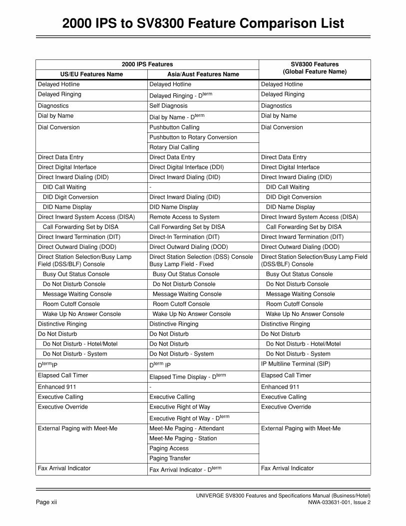
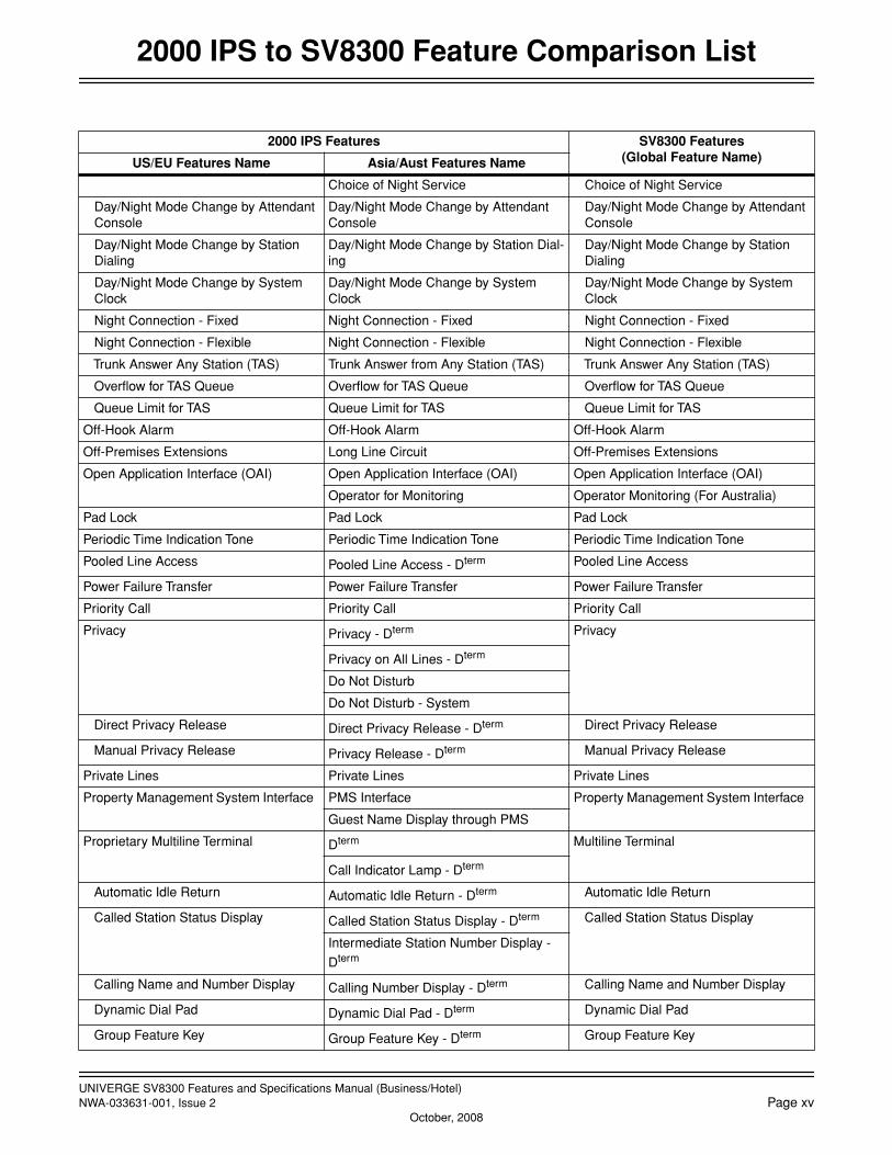
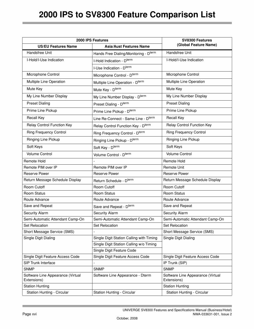
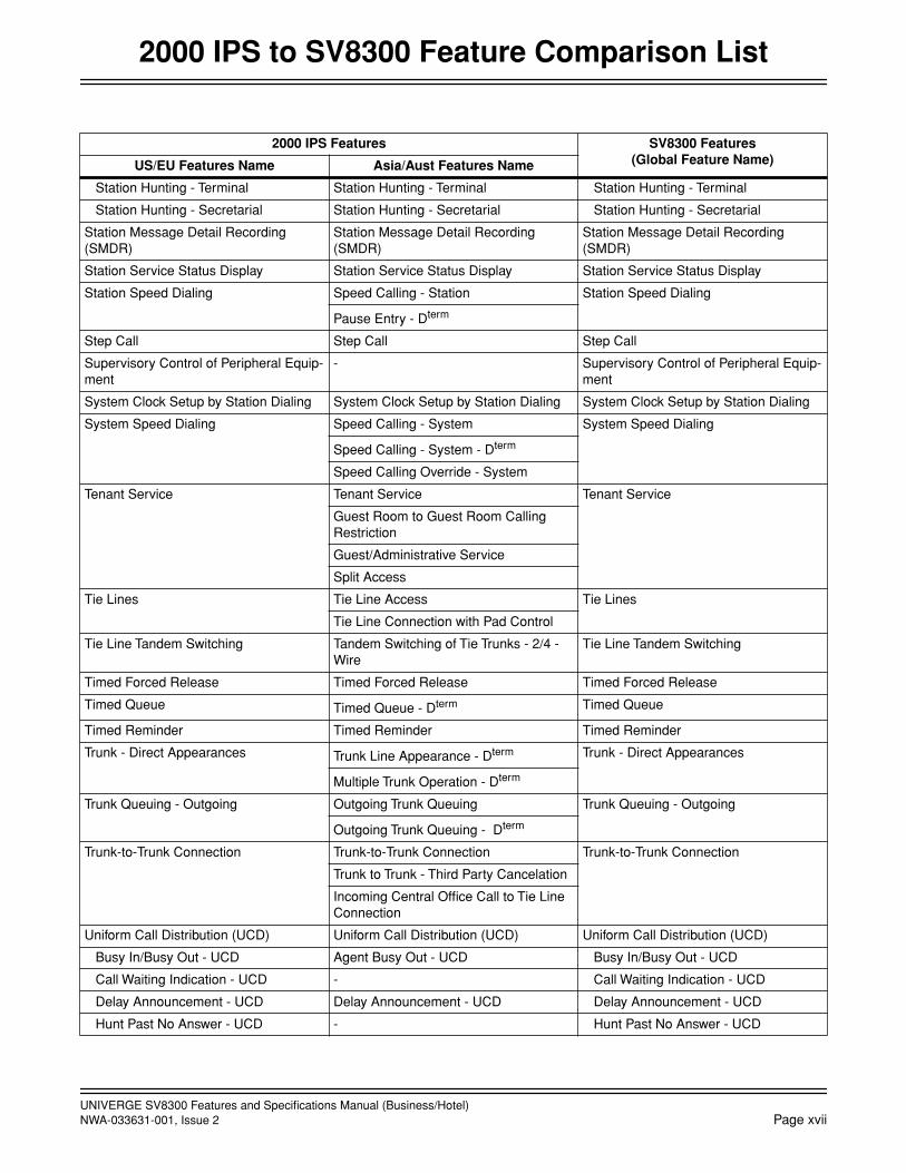
2000 IPS to SV8300 Feature Comparison List
2000 IPS Features SV8300 Features(Global Feature Name)US/EU Features Name Asia/Aust Features Name
Account Code Account Code Account Code
Account Code - Attendant
Account Code - D
term
Add-On Module Add-On Module - D
term
Add-On Module
Alarm Indications Alarm Indications Alarm Indications
Alphanumeric Display Alphanumeric Display - D
term
Alphanumeric Display
Name Display - D
term
Announcement Service Announcement Service Announcement Service
Answer Key Automatic Hold - D
term
Answer Key
Attendant Assisted Calling Delay Operation Attendant Assisted Calling
Dial Access to Attendant
Non-Delay Operation
Passing Dial Tone
Attendant Camp-On Attendant Camp-on with Tone Indication Attendant Camp-On
Attendant Console Attendant Console
Call Processing Indication
Attendant Called/Calling Name Display - Attendant Called/Calling Name Display
Attendant Called/Calling Number Called Number Display - Attendant Attendant Called/Calling Number
Digital Display - Station
Digital Display - Trunk
Attendant Call Selection Incoming Call Identification Attendant Call Selection
Attendant Console Lockout - Password Attendant Console Lockout - Password Attendant Console Lockout - Password
Attendant Do Not Disturb Setup and Cancel
Do Not Disturb Attendant Do Not Disturb Setup and CancelDo Not Disturb - System
Attendant Interposition Calling/Transfer Inter-Position Calling Attendant Interposition
Inter-Position Transfer
Attendant Lamp Check Lamp Check Attendant Lamp Check
Attendant Listed Directory Number Listed Directory Number Display - Atten-dant
Attendant Listed Directory Number
Attendant Loop Release Attendant Loop Release Attendant Loop Release
Attendant Programming - Attendant Programming
Attendant Speed Calling - System Set Up
Attendant Training Jacks Attendant Training Jacks Attendant Training Jacks
Audible Indication Control Audible Indication Control Audible Indication Control
Call Processing Indication Call Processing Indication Call Processing Indication
Call Queuing Call Queuing Call Queuing
Call Splitting Splitting Call Splitting
Call Waiting Display Call Waiting Display Call Waiting Display

UNIVERGE SV8300 Features and Specifications Manual (Business/Hotel)NWA-033631-001, Issue 2
Page ix
October, 2008
2000 IPS to SV8300 Feature Comparison List
Common Route Indial Common Route Indial Common Route Indial
Dialed Number Identification Service (DNIS)
Dialed Number Identification Service (DNIS)
Dialed Number Identification Service (DNIS)
Incoming Call Identification Incoming Call Identification Incoming Call Identification
Individual Trunk Access Individual Trunk Access Individual Trunk Access
Multi-Function Key Multi-Function Key - Attendant Multi-Function Key
Multiple Console Operation Multiple Console Operation Multiple Console Operation
Pushbutton Calling - Attendant Only Pushbutton Calling - Attendant Only Pushbutton Calling - Attendant Only
Serial Call Serial Call Serial Call
Time Display Time Display Time Display
Trunk Group Busy Display Trunk Group Busy Display Trunk Group Busy Display
Unsupervised Trunk-to-Trunk Transfer By Attendant
Trunk to Trunk Transfer Before Answer by Attendant Console
Unsupervised Trunk-to-Trunk Transfer By Attendant
Attendant Delay Announcement Attendant Delay Announcement Attendant Delay Announcement
Attendant Lockout Attendant Lockout Attendant Lockout
Attendant Overflow Automatic Change of Night Service Attendant Overflow
Attendant Override Attendant Override Attendant Override
Authorization Code Authorization Code Authorization Code
Automated Attendant Automated Attendant Automated Attendant
Automatic Call Distribution (ACD) - Automatic Call Distribution (ACD)
Busy In/Busy Out - ACD - Busy In/Busy Out - ACD
Call Waiting Indication - ACD - Call Waiting Indication - ACD
Delay Announcement - ACD - Delay Announcement - ACD
Hunt Past No Answer - ACD - Hunt Past No Answer - ACD
Immediate Overflow - ACD - Immediate Overflow - ACD
Priority Queuing - ACD - Priority Queuing - ACD
Queue Size Control - ACD - Queue Size Control - ACD
Silent Monitor - ACD - Silent Monitor - ACD
Automatic Call Distribution (ACD) with Management Information System (MIS)
Automatic Call Distribution (ACD)/Man-agement Information System(MIS)
Automatic Call Distribution (ACD) with Management Information System (MIS)
Automatic Camp-On Automatic Camp-On Automatic Camp-On
Automatic Change to Daylight Saving Time
Automatic Change to Daylight Saving Time
Automatic Change to Daylight Saving Time
Automatic Number Identification (ANI) - Automatic Number Identification (ANI)
Automatic Recall Automatic Recall Automatic Recall
Automatic Recall - D
term
Automatic Wake-Up Automatic Wake-Up Automatic Wake-Up
Bandwidth Control Bandwidth Control Bandwidth Control
2000 IPS Features SV8300 Features(Global Feature Name)US/EU Features Name Asia/Aust Features Name

UNIVERGE SV8300 Features and Specifications Manual (Business/Hotel)
Page x
NWA-033631-001, Issue 2October, 2008
2000 IPS to SV8300 Feature Comparison List
Boss/Secretary Calling Boss-Secretary - Message Waiting Lamp Control
Boss/Secretary Calling
Boss-Secretary Override - D
term
Boss-Secretary Transfer - D
term
Broker’s Call Broker’s Call Broker’s Call
Call Back Call Back Call Back
Call Back - Don’t Answer
Call Back - D
term
Call Back - Multiple Assignment
Call Forwarding - Call Forwarding Call Forwarding set/reset by MAT/CAT
Attendant Call Forwarding Setup and Cancel
- Attendant Call Forwarding Setup and Cancel
Call Forwarding - All Calls Call Forwarding - All Calls Call Forwarding - All Calls
Call Forwarding - All Calls - D
term
Call Forwarding - All Calls - Outside
Call Forwarding - Busy Line Call Forwarding - Busy Line Call Forwarding - Busy Line
Call Forwarding - Busy Line - D
term
Call Forwarding - Busy Line - Outside
Call Forwarding - No Answer Call Forwarding - Don’t Answer Call Forwarding - No Answer
Call Forwarding - Don’t Answer - D
term
Call Forwarding - Don’t Answer - Outside
Call Forwarding - Destination Call Forwarding - I’m Here Call Forwarding - Destination
Multiple Call Forwarding - All Calls Multiple Call Forwarding - All Calls Multiple Call Forwarding - All Calls
Multiple Call Forwarding - Busy Line Multiple Call Forwarding - Busy Line Multiple Call Forwarding - Busy Line
Multiple Call Forwarding - No Answer Multiple Call Forwarding - Don't Answer Multiple Call Forwarding - No Answer
Split Call Forwarding - All Calls Split Call Forwarding - All Calls Split Call Forwarding - All Calls
Split Call Forwarding - Busy Line Split Call Forwarding - Busy Line Split Call Forwarding - Busy Line
Split Call Forwarding - No Answer Split Call Forwarding - Don’t Answer Split Call Forwarding - No Answer
Call Forwarding - Logout (D
term
IP) Call Forwarding - Logout (D
term
IP) Call Forwarding - Logout
Call Forwarding - Override Call Forwarding - Override Call Forwarding - Override
Group Diversion Group Diversion Group Diversion
Call Park Call Park - D
term
Call Park
Call Park - System Call Park - System Call Park - System
Call Park - Tenant Call Park - Tenant Call Park - Tenant
Call Pickup - Call Pickup
Call Pickup - Direct Call Pickup - Direct Call Pickup - Direct
Call Pickup - Group Call Pickup - Group Call Pickup - Group
Call Pickup - Group - D
term
2000 IPS Features SV8300 Features(Global Feature Name)US/EU Features Name Asia/Aust Features Name

UNIVERGE SV8300 Features and Specifications Manual (Business/Hotel)NWA-033631-001, Issue 2
Page xi
October, 2008
2000 IPS to SV8300 Feature Comparison List
Call Pickup - Designated Group Call Pickup - Designated Group Call Pickup - Designated Group
Call Redirect Call Redirect Call Redirect
Call Transfer - Call Transfer
Call Transfer - All Calls Call Transfer - All Calls Call Transfer - All Calls
Call Transfer - All Calls - D
term
Call Transfer - Attendant Call Transfer - Attendant Call Transfer - Attendant
Caller ID
Caller ID Class Caller ID Class Caller ID Class
Caller ID Display Caller ID Display Caller ID Display
Caller ID - Station Caller ID - Station Caller ID - Station
Caller ID - Station (ETSI - FSK) - Caller ID - Station (ETSI - FSK)
CID Call Routing CID Call Routing CID Call Routing
No CID Call Routing No CID Call Routing No CID Call Routing
Camp-On Call Waiting - Station Camp-On / Call Waiting
Call Waiting - Terminating
Call Waiting Answer - D
term
Station Camp-On
Centrex Compatibility - Centrex Compatibility
Check In/Check Out Check In/Check Out Check In/Check Out
Stack Dial - Attendant Call History
CID Call Back CID Call Back Incoming Call History (CID Call Back)
Stack Dial Stack Dial - Attendant Outgoing Call History (Stack Dial)
Stack Dial - D
term
Class of Service Class of Service - Individual Class of Service
Miscellaneous Trunk Restriction
Code Restriction Toll Denial/Toll Diversion Code Restriction
Toll Restriction - Total Digit Count
Toll Restriction -3/6 - Digit
Restriction from Outgoing Calls
Conference (Three/Four Party) Add-On Conference - D
term
Conference (Three/Four Party)
Three-Way Calling
Conference (32 Party) Conference (32 Party) Conference (32 Party)
Group Call Group Call Group Call
Meet-Me Conference Meet-Me Conference Meet-Me Conference
Consecutive Speed Dialing Consecutive Speed Calling Consecutive Speed Dialing
Consultation Hold Consultation Hold - All Calls Consultation Hold
Consultation Hold - All Calls - D
term
Customer Administration Terminal (CAT) Customer Administration Terminal (CAT) Customer Administration Terminal (CAT)
Data Line Security Data Line Security Data Line Security
2000 IPS Features SV8300 Features(Global Feature Name)US/EU Features Name Asia/Aust Features Name
UNIVERGE SV8300 Features and Specifications Manual (Business/Hotel)
Page xii
NWA-033631-001, Issue 2
2000 IPS to SV8300 Feature Comparison List
Delayed Hotline Delayed Hotline Delayed Hotline
Delayed Ringing Delayed Ringing - D
term
Delayed Ringing
Diagnostics Self Diagnosis Diagnostics
Dial by Name Dial by Name - D
term
Dial by Name
Dial Conversion Pushbutton Calling Dial Conversion
Pushbutton to Rotary Conversion
Rotary Dial Calling
Direct Data Entry Direct Data Entry Direct Data Entry
Direct Digital Interface Direct Digital Interface (DDI) Direct Digital Interface
Direct Inward Dialing (DID) Direct Inward Dialing (DID) Direct Inward Dialing (DID)
DID Call Waiting - DID Call Waiting
DID Digit Conversion Direct Inward Dialing (DID) DID Digit Conversion
DID Name Display DID Name Display DID Name Display
Direct Inward System Access (DISA) Remote Access to System Direct Inward System Access (DISA)
Call Forwarding Set by DISA Call Forwarding Set by DISA Call Forwarding Set by DISA
Direct Inward Termination (DIT) Direct-In Termination (DIT) Direct Inward Termination (DIT)
Direct Outward Dialing (DOD) Direct Outward Dialing (DOD) Direct Outward Dialing (DOD)
Direct Station Selection/Busy Lamp Field (DSS/BLF) Console
Direct Station Selection (DSS) Console Busy Lamp Field - Fixed
Direct Station Selection/Busy Lamp Field (DSS/BLF) Console
Busy Out Status Console Busy Out Status Console Busy Out Status Console
Do Not Disturb Console Do Not Disturb Console Do Not Disturb Console
Message Waiting Console Message Waiting Console Message Waiting Console
Room Cutoff Console Room Cutoff Console Room Cutoff Console
Wake Up No Answer Console Wake Up No Answer Console Wake Up No Answer Console
Distinctive Ringing Distinctive Ringing Distinctive Ringing
Do Not Disturb Do Not Disturb Do Not Disturb
Do Not Disturb - Hotel/Motel Do Not Disturb Do Not Disturb - Hotel/Motel
Do Not Disturb - System Do Not Disturb - System Do Not Disturb - System
D
term
IP D
term
IP IP Multiline Terminal (SIP)
Elapsed Call Timer Elapsed Time Display - D
term
Elapsed Call Timer
Enhanced 911 - Enhanced 911
Executive Calling Executive Calling Executive Calling
Executive Override Executive Right of Way Executive Override
Executive Right of Way - D
term
External Paging with Meet-Me Meet-Me Paging - Attendant External Paging with Meet-Me
Meet-Me Paging - Station
Paging Access
Paging Transfer
Fax Arrival Indicator Fax Arrival Indicator - D
term
Fax Arrival Indicator
2000 IPS Features SV8300 Features(Global Feature Name)US/EU Features Name Asia/Aust Features Name

UNIVERGE SV8300 Features and Specifications Manual (Business/Hotel)NWA-033631-001, Issue 2
Page xiii
October, 2008
2000 IPS to SV8300 Feature Comparison List
FAX over IP FAX over IP FAX over IP
Feature Activation from Secondary Extension
Feature Activation from Subline - D
term
Feature Activation from Secondary Extension
Flexible Line Key Assignment Non-Square Line Assignment - D
term
Flexible Line Key Assignment
Flexible Numbering Plan Flexible Numbering of Stations Flexible Numbering Plan
Flexible Ringing Assignment Flexible Ringing Assignment - D
term
Flexible Ringing Assignment
Forced Account Code Forced Account Code Forced Account Code
Group Call by Pilot Number Dialing Group Call by Pilot Number Dialing Group Call by Pilot Number Dialing
Group Listening Group Listening - D
term
Group Listening
Handsfree Answerback Hands Free Answer Back - D
term
Handsfree Answerback
Handsfree Dialing and Monitoring Hands Free Dialing/Monitoring - D
term
Handsfree Dialing and Monitoring
Hold - Hold
Automatic Hold Automatic Hold - D
term
Automatic Hold
Call Hold Call Hold Call Hold
Call Hold - D
term
Dual Hold Dual Hold - D
term
Dual Hold
Exclusive Hold Exclusive Hold - D
term
Exclusive Hold
Non-exclusive Hold Non-exclusive Hold - D
term
Non-exclusive Hold
Hotel/Motel Attendant Console Hotel Console Hotel/Motel Attendant Console
Hotel/Motel DID Number Allocation to Guest Station
Hotel/Motel DID Number Allocation to Guest Station
Hotel/Motel DID Number Allocation to Guest Station
Hotel/Motel Front Desk Instrument Hotel/Motel Front Desk Terminal Hotel/Motel Front Desk Instrument Printer Control - Front Desk Terminal
Call Information System (CIS)
Hotel/Motel Toll Restriction Change - Guest Station
Hotel/Motel Toll Restriction Change - Guest Station
Hotel/Motel Toll Restriction Change - Guest Station
Hotline - Inside/Outside Hot Line Hotline - Inside/Outside
Hot Line - Outside
House Phone House Phone House Phone
Individual Attendant Access Individual Attendant Access Individual Attendant Access
Intercept Announcement Call Forwarding - Intercept Announce-ment
Intercept Announcement
Intercom Intercom
Manual Intercom Manual Intercom - D
term
Manual Intercom
Automatic Intercom Automatic Intercom - D
term
Automatic Intercom
Dial Intercom Dial Intercom - D
term
Dial Intercom
Internal Tone/Voice Signaling Single Digit Feature Access Code Internal Tone/Voice Signaling
Voice Call - Attendant
Voice Call - D
term
2000 IPS Features SV8300 Features(Global Feature Name)US/EU Features Name Asia/Aust Features Name

UNIVERGE SV8300 Features and Specifications Manual (Business/Hotel)
Page xiv
NWA-033631-001, Issue 2October, 2008
2000 IPS to SV8300 Feature Comparison List
Internal Zone Paging with Meet-Me Meet-Me Paging - Attendant Internal Zone Paging with Meet-Me
Meet-Me Paging - Station
Paging Access
Paging Transfer
IP Enabled D
term
IP Enabled D
term
IP Multiline Terminal (SIP)
Last Number Redial Last Number Call Last Number Redial
Last Number Call - Attendant
Last Number Call - D
term
Least Cost Routing - 3/6 Digit Least Cost Routing - 3/6 Digit Least Cost Routing - 3/6 Digit
Least Cost Routing - Time of Day Rout-ing
Line Lockout Line Lockout Line Lockout
Howler Tone Sending
Line Preselection Line Preselection - D
term
Line Preselection
Maid Status Maid Status Maid Status
Maintenance Administration Terminal (MAT)
Maintenance Administration Terminal (MAT)
PC Programming
Password
Remote System Data Change
Message Center Interface (MCI) Message Center Interface (MCI) Message Center Interface (MCI)
Message Registration Message Registration Message Registration
Message Reminder Message Reminder - D
term Message Reminder
Message Waiting Message Waiting Message Waiting
Miscellaneous Trunk Access Miscellaneous Trunk Access Miscellaneous Trunk Access
CCSA Access - CCSA Access
Code Calling Equipment Access Code Calling Access Code Calling Equipment Access
Dictation Equipment Access Dictation Access Dictation Equipment Access
Foreign Exchange (FX) Access - Foreign Exchange (FX) Access
Radio Paging Equipment Access Radio Paging Radio Paging Equipment Access
Wide Area Telephone Service (WATS) Access
- Wide Area Telephone Service (WATS) Access
Mobility Access Mobility Access Mobility Access
Modem over IP Modem over IP Modem over IP
MP Program Download (FTP) MP Program Download (FTP) Remote System Upgrade
Multiple Language Display Multiple Language Display Multiple Language Display
Multiple Terminal Attendant Position Attendant Terminal - Dterm Multiple Terminal Attendant Position
Music On Hold Music On Hold Music On Hold
Night Service Night Service
Attendant Night Transfer Attendant Night Transfer Attendant Night Transfer
Call Rerouting - Call Rerouting
2000 IPS Features SV8300 Features(Global Feature Name)US/EU Features Name Asia/Aust Features Name
UNIVERGE SV8300 Features and Specifications Manual (Business/Hotel)NWA-033631-001, Issue 2 Page xv
October, 2008
2000 IPS to SV8300 Feature Comparison List
Choice of Night Service Choice of Night Service
Day/Night Mode Change by Attendant Console
Day/Night Mode Change by Attendant Console
Day/Night Mode Change by Attendant Console
Day/Night Mode Change by Station Dialing
Day/Night Mode Change by Station Dial-ing
Day/Night Mode Change by Station Dialing
Day/Night Mode Change by System Clock
Day/Night Mode Change by System Clock
Day/Night Mode Change by System Clock
Night Connection - Fixed Night Connection - Fixed Night Connection - Fixed
Night Connection - Flexible Night Connection - Flexible Night Connection - Flexible
Trunk Answer Any Station (TAS) Trunk Answer from Any Station (TAS) Trunk Answer Any Station (TAS)
Overflow for TAS Queue Overflow for TAS Queue Overflow for TAS Queue
Queue Limit for TAS Queue Limit for TAS Queue Limit for TAS
Off-Hook Alarm Off-Hook Alarm Off-Hook Alarm
Off-Premises Extensions Long Line Circuit Off-Premises Extensions
Open Application Interface (OAI) Open Application Interface (OAI) Open Application Interface (OAI)
Operator for Monitoring Operator Monitoring (For Australia)
Pad Lock Pad Lock Pad Lock
Periodic Time Indication Tone Periodic Time Indication Tone Periodic Time Indication Tone
Pooled Line Access Pooled Line Access - Dterm Pooled Line Access
Power Failure Transfer Power Failure Transfer Power Failure Transfer
Priority Call Priority Call Priority Call
Privacy Privacy - Dterm Privacy
Privacy on All Lines - Dterm
Do Not Disturb
Do Not Disturb - System
Direct Privacy Release Direct Privacy Release - Dterm Direct Privacy Release
Manual Privacy Release Privacy Release - Dterm Manual Privacy Release
Private Lines Private Lines Private Lines
Property Management System Interface PMS Interface Property Management System Interface
Guest Name Display through PMS
Proprietary Multiline Terminal Dterm Multiline Terminal
Call Indicator Lamp - Dterm
Automatic Idle Return Automatic Idle Return - Dterm Automatic Idle Return
Called Station Status Display Called Station Status Display - Dterm Called Station Status Display
Intermediate Station Number Display -
Dterm
Calling Name and Number Display Calling Number Display - Dterm Calling Name and Number Display
Dynamic Dial Pad Dynamic Dial Pad - Dterm Dynamic Dial Pad
Group Feature Key Group Feature Key - Dterm Group Feature Key
2000 IPS Features SV8300 Features(Global Feature Name)US/EU Features Name Asia/Aust Features Name
UNIVERGE SV8300 Features and Specifications Manual (Business/Hotel)Page xvi NWA-033631-001, Issue 2
October, 2008
2000 IPS to SV8300 Feature Comparison List
Handsfree Unit Hands Free Dialing/Monitoring - Dterm Handsfree Unit
I-Hold/I-Use Indication I-Hold Indication - Dterm I-Hold/I-Use Indication
I-Use Indication - Dterm
Microphone Control Microphone Control - Dterm Microphone Control
Multiple Line Operation Multiple Line Operation - Dterm Multiple Line Operation
Mute Key Mute Key - Dterm Mute Key
My Line Number Display My Line Number Display - Dterm My Line Number Display
Preset Dialing Preset Dialing - Dterm Preset Dialing
Prime Line Pickup Prime Line Pickup - Dterm Prime Line Pickup
Recall Key Line Re-Connect - Same Line - Dterm Recall Key
Relay Control Function Key Relay Control Function Key - Dterm Relay Control Function Key
Ring Frequency Control Ring Frequency Control - Dterm Ring Frequency Control
Ringing Line Pickup Ringing Line Pickup - Dterm Ringing Line Pickup
Soft Keys Soft Key - Dterm Soft Keys
Volume Control Volume Control - Dterm Volume Control
Remote Hold - Remote Hold
Remote PIM over IP Remote PIM over IP Remote Unit
Reserve Power Reserve Power Reserve Power
Return Message Schedule Display Return Schedule - Dterm Return Message Schedule Display
Room Cutoff Room Cutoff Room Cutoff
Room Status Room Status Room Status
Route Advance Route Advance Route Advance
Save and Repeat Save and Repeat - Dterm Save and Repeat
Security Alarm Security Alarm Security Alarm
Semi-Automatic Attendant Camp-On Semi-Automatic Attendant Camp-On Semi-Automatic Attendant Camp-On
Set Relocation Set Relocation Set Relocation
Short Message Service (SMS) - Short Message Service (SMS)
Single Digit Dialing Single Digit Station Calling with Timing Single Digit Dialing
Single Digit Station Calling w/o Timing
Single Digit Feature Code
Single Digit Feature Access Code Single Digit Feature Access Code Single Digit Feature Access Code
SIP Trunk Interface - IP Trunk (SIP)
SNMP SNMP SNMP
Software Line Appearance (Virtual Extensions)
Software Line Appearance - Dterm Software Line Appearance (Virtual Extensions)
Station Hunting Station Hunting
Station Hunting - Circular Station Hunting - Circular Station Hunting - Circular
2000 IPS Features SV8300 Features(Global Feature Name)US/EU Features Name Asia/Aust Features Name
UNIVERGE SV8300 Features and Specifications Manual (Business/Hotel)NWA-033631-001, Issue 2 Page xvii
2000 IPS to SV8300 Feature Comparison List
Station Hunting - Terminal Station Hunting - Terminal Station Hunting - Terminal
Station Hunting - Secretarial Station Hunting - Secretarial Station Hunting - Secretarial
Station Message Detail Recording (SMDR)
Station Message Detail Recording (SMDR)
Station Message Detail Recording (SMDR)
Station Service Status Display Station Service Status Display Station Service Status Display
Station Speed Dialing Speed Calling - Station Station Speed Dialing
Pause Entry - Dterm
Step Call Step Call Step Call
Supervisory Control of Peripheral Equip-ment
- Supervisory Control of Peripheral Equip-ment
System Clock Setup by Station Dialing System Clock Setup by Station Dialing System Clock Setup by Station Dialing
System Speed Dialing Speed Calling - System System Speed Dialing
Speed Calling - System - Dterm
Speed Calling Override - System
Tenant Service Tenant Service Tenant Service
Guest Room to Guest Room Calling Restriction
Guest/Administrative Service
Split Access
Tie Lines Tie Line Access Tie Lines
Tie Line Connection with Pad Control
Tie Line Tandem Switching Tandem Switching of Tie Trunks - 2/4 - Wire
Tie Line Tandem Switching
Timed Forced Release Timed Forced Release Timed Forced Release
Timed Queue Timed Queue - Dterm Timed Queue
Timed Reminder Timed Reminder Timed Reminder
Trunk - Direct Appearances Trunk Line Appearance - Dterm Trunk - Direct Appearances
Multiple Trunk Operation - Dterm
Trunk Queuing - Outgoing Outgoing Trunk Queuing Trunk Queuing - Outgoing
Outgoing Trunk Queuing - Dterm
Trunk-to-Trunk Connection Trunk-to-Trunk Connection Trunk-to-Trunk Connection
Trunk to Trunk - Third Party Cancelation
Incoming Central Office Call to Tie Line Connection
Uniform Call Distribution (UCD) Uniform Call Distribution (UCD) Uniform Call Distribution (UCD)
Busy In/Busy Out - UCD Agent Busy Out - UCD Busy In/Busy Out - UCD
Call Waiting Indication - UCD - Call Waiting Indication - UCD
Delay Announcement - UCD Delay Announcement - UCD Delay Announcement - UCD
Hunt Past No Answer - UCD - Hunt Past No Answer - UCD
2000 IPS Features SV8300 Features(Global Feature Name)US/EU Features Name Asia/Aust Features Name
UNIVERGE SV8300 Features and Specifications Manual (Business/Hotel)Page xviii NWA-033631-001, Issue 2
2000 IPS to SV8300 Feature Comparison List
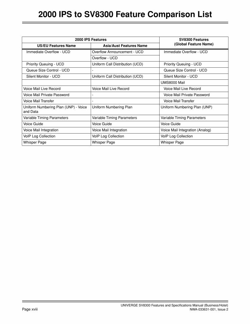
Immediate Overflow - UCD Overflow Announcement - UCD Immediate Overflow - UCD
Overflow - UCD
Priority Queuing - UCD Uniform Call Distribution (UCD) Priority Queuing - UCD
Queue Size Control - UCD - Queue Size Control - UCD
Silent Monitor - UCD Uniform Call Distribution (UCD) Silent Monitor - UCD
UMS8000 Mail
Voice Mail Live Record Voice Mail Live Record Voice Mail Live Record
Voice Mail Private Password - Voice Mail Private Password
Voice Mail Transfer - Voice Mail Transfer
Uniform Numbering Plan (UNP) - Voice and Data
Uniform Numbering Plan Uniform Numbering Plan (UNP)
Variable Timing Parameters Variable Timing Parameters Variable Timing Parameters
Voice Guide Voice Guide Voice Guide
Voice Mail Integration Voice Mail Integration Voice Mail Integration (Analog)
VoIP Log Collection VoIP Log Collection VoIP Log Collection
Whisper Page Whisper Page Whisper Page
2000 IPS Features SV8300 Features(Global Feature Name)US/EU Features Name Asia/Aust Features Name

UNIVERGE SV8300 Features and Specifications Manual (Business/Hotel)NWA-033631-001, Issue 2 Page 1
Account Code
Account Code
General Description
This feature, when used with Station Message Detail Recording (SMDR), allows station users and Attendantsto enter a cost accounting or client billing code (up to 10 digits) into the system.
Station Application
All stations.
Operating Procedure
To enter an Account Code from a station before accessing an outside line
1. Lift the handset and receive dial tone.
2. Enter the Account Code feature access code or press the Account Code feature access key.
3. Enter the Account Code.
4. Receive dial tone and dial the desired number (including outside line access code).
To enter an Account Code while connected to an outside line
From a Multiline Terminal
1. Press Account Code feature access key and conversation continues.
2. Enter the Account Code.
From the Attendant Console
1. While connected to an outside line, press the START key only if an outgoing call.
2. Enter the Account Code feature access code.
3. Enter the Account Code.
4. Dial the desired station number.
From a Single Line Telephone
1. Press the FLASH key (or momentarily press the hookswitch) and receive feature dial tone.
2. Enter the Account Code feature access code.
3. Enter the Account Code and receive feature dial tone again.
4. Return to the original outside line by pressing the FLASH key (or momentarily pressing the hookswitch).
OR
Dial a station number to transfer the call.

UNIVERGE SV8300 Features and Specifications Manual (Business/Hotel)Page 2 NWA-033631-001, Issue 2
Account Code
Service Conditions
1. The maximum number of digits in an Account Code is 10. There is no limitation to the number of AccountCodes used per system. The feature access code for Account Code entry can be one to four digits.
2. A station user can enter an Account Code consisting of fewer digits than the maximum length defined andindicate the end of the entry by pressing the # key. Therefore, the # key cannot be part of an Account Code.
3. Account Code entry can be performed with an outside party on Consultation Hold. In this case, feature dialtone is received instead of dial tone after entering the Account Code.
4. Stations are assigned this feature through Class of Service.
5. Account Codes can be output in the Station Message Detail Call Recording (SMDR) or Hotel PropertyManagement System (PMS).
6. Account Codes can be output in the SMDR record for calls handled by Trunk Queuing – Outgoing duringconnection to the outside line.
7. When multiple Account Codes are entered for the same call, only the last code entered will be recorded bySMDR.
8. If the system is set to comply with KF Registration, this feature only allows an Account Code to be inputwhile the outside line is seized.
UNIVERGE SV8300 Features and Specifications Manual (Business/Hotel)NWA-033631-001, Issue 2 Page 3
October, 2008
Add-On Module
Add-On Module
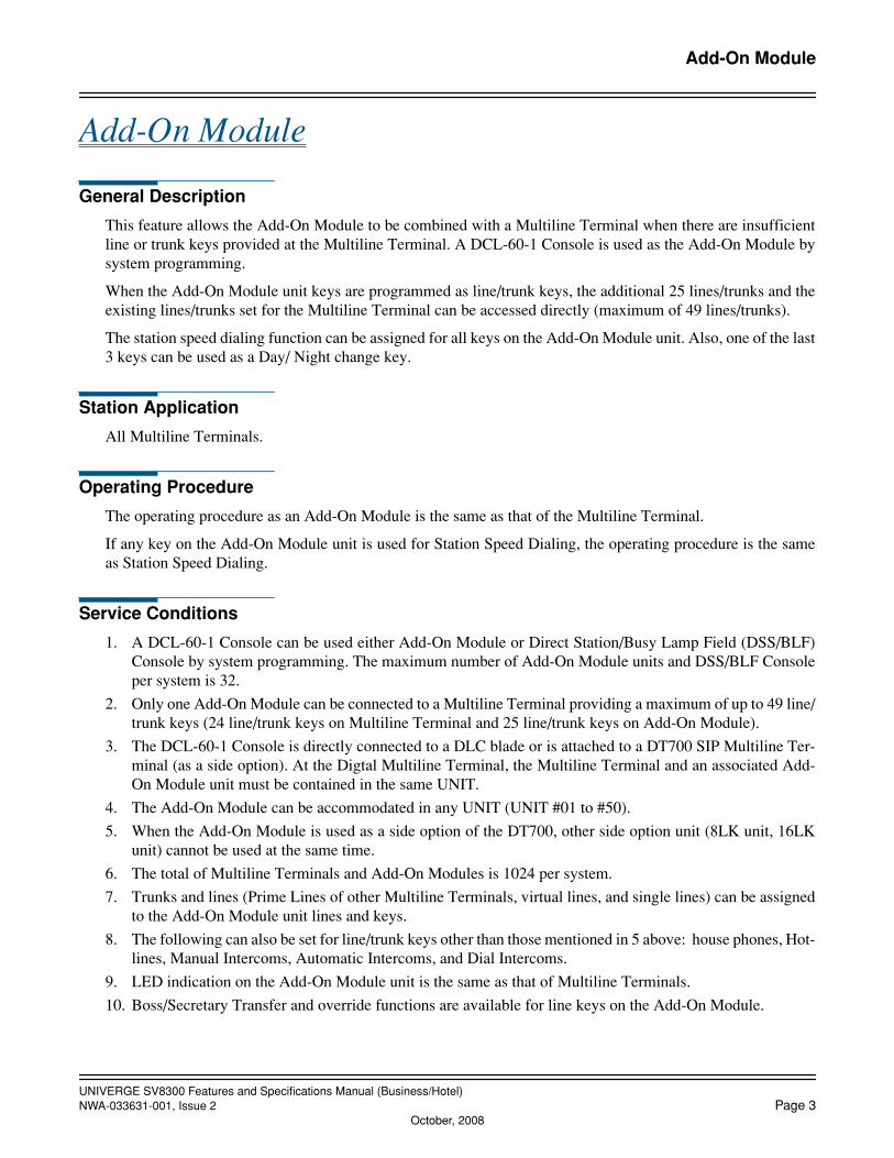
General Description
This feature allows the Add-On Module to be combined with a Multiline Terminal when there are insufficientline or trunk keys provided at the Multiline Terminal. A DCL-60-1 Console is used as the Add-On Module bysystem programming.
When the Add-On Module unit keys are programmed as line/trunk keys, the additional 25 lines/trunks and theexisting lines/trunks set for the Multiline Terminal can be accessed directly (maximum of 49 lines/trunks).
The station speed dialing function can be assigned for all keys on the Add-On Module unit. Also, one of the last3 keys can be used as a Day/ Night change key.
Station Application
All Multiline Terminals.
Operating Procedure
The operating procedure as an Add-On Module is the same as that of the Multiline Terminal.
If any key on the Add-On Module unit is used for Station Speed Dialing, the operating procedure is the sameas Station Speed Dialing.
Service Conditions
1. A DCL-60-1 Console can be used either Add-On Module or Direct Station/Busy Lamp Field (DSS/BLF)Console by system programming. The maximum number of Add-On Module units and DSS/BLF Consoleper system is 32.
2. Only one Add-On Module can be connected to a Multiline Terminal providing a maximum of up to 49 line/trunk keys (24 line/trunk keys on Multiline Terminal and 25 line/trunk keys on Add-On Module).
3. The DCL-60-1 Console is directly connected to a DLC blade or is attached to a DT700 SIP Multiline Ter-minal (as a side option). At the Digtal Multiline Terminal, the Multiline Terminal and an associated Add-On Module unit must be contained in the same UNIT.
4. The Add-On Module can be accommodated in any UNIT (UNIT #01 to #50).
5. When the Add-On Module is used as a side option of the DT700, other side option unit (8LK unit, 16LKunit) cannot be used at the same time.
6. The total of Multiline Terminals and Add-On Modules is 1024 per system.
7. Trunks and lines (Prime Lines of other Multiline Terminals, virtual lines, and single lines) can be assignedto the Add-On Module unit lines and keys.
8. The following can also be set for line/trunk keys other than those mentioned in 5 above: house phones, Hot-lines, Manual Intercoms, Automatic Intercoms, and Dial Intercoms.
9. LED indication on the Add-On Module unit is the same as that of Multiline Terminals.
10. Boss/Secretary Transfer and override functions are available for line keys on the Add-On Module.

UNIVERGE SV8300 Features and Specifications Manual (Business/Hotel)Page 4 NWA-033631-001, Issue 2
Add-On Module
11. If a line/trunk on the Add-On Module unit is called, the ringer of the connected Multiline Terminal rings.The Multiline Terminal volume is used to control the ringer volume.
12. For details on Station Speed Dialing keys, refer to the Station Speed Dialing feature. One of the last threekeys can be used as Day/Night key.
13. The Add-On Module unit uses one system capacity port in either a DLC connection or used as a side optionof DT700. No IP port license is required when used as a side option.
14. Up to 25 lines and trunks can be assigned for the Add-On Module. The delayed ringing function is onlyavailable for the first 16 lines and trunks assigned.

UNIVERGE SV8300 Features and Specifications Manual (Business/Hotel)NWA-033631-001, Issue 2 Page 5
Alarm Indications
Alarm Indications
General Description
Faults are indicated on the alarm lamp located front panel of the CPU blade.
Station Application
Not applicable.
Operating Procedure
No manual operation is required.
Service Conditions
1. The following table shows a standard pattern of the faults that can be detected and their alarm indications.If required, the following alarm indications (Red lighting (MJ), Red flashing(MN), or No indication) canbe changed on an individual fault basis. Refer to the Maintenance Manual for more information.
Note 1: MJ ALARM is always displayed for power failure regardless of programming.Note 2: When UNIT/DLC, which accommodates the Multiline Terminal, becomes unusual, Alarm Indications can-
not be displayed.
2. Normal operation of the CPU is indicated by a green flashing (120 ipm) “run” LED located on the CPU.
Contents of alarm
Alarm indications
Alarm lamp on CPU blade
Multiline Terminal Alarm
MJ MN MJ MN
System reset X X — —
Blade Reset X X X (Note 2) X (Note 2)
Link failure between UNIT#1 and other UNITs X X X (Note 2) X (Note 2)
Blade down X X X (Note 2) X (Note 2)
DTI line failure X X X (Note 2) X (Note 2)
DCH link failure X X X (Note 2) X (Note 2)
CCH link failure X X X (Note 2) X (Note 2)
SIP trunk failure X X X (Note 2) X (Note 2)
LAN interface failure (SMDR, PMS, OAI) X X X (Note 2) X (Note 2)
Number of lockout stations was more than a fixed number X X X (Note 2) X (Note 2)
DLC line error X X X (Note 2) X (Note 2)
Power alarm Note 1
• AC input down X X X (Note 2) X (Note 2)
• DC output down X X X (Note 2) X (Note 2)
Alarm for pre-determined time (for routine maintenance) X X X X

UNIVERGE SV8300 Features and Specifications Manual (Business/Hotel)Page 6 NWA-033631-001, Issue 2
Alarm Indications
3. In case that system is stopped at predetermined time, when system starts, a fault message is stored and analarm is sent.
4. Alarm indication to Multiline Terminal lamp;
a. The maximum number of Multiline Terminals per system is two.
b. In case of MN alarm: Red flashing (60 ipm)
c. In case of MJ alarm: Red lighting (included MN + MJ)
d. When system is reset after lighting alarm lamp, alarm indication will go off.(Fault information is remained)

UNIVERGE SV8300 Features and Specifications Manual (Business/Hotel)NWA-033631-001, Issue 2 Page 7
Alphanumeric Display
Alphanumeric Display
General Description
The LCD on Multiline Terminal is used to provide alphanumeric information including clock/calendar and callprocessing information.
The station names (up to 16 characters) and trunk names (up to 8 characters) can be assigned from a PCPro orCustomer Administration Terminal (CAT). The station name can also be programmed or changed from the us-er’s Multiline Terminal.
Station Application
All Multiline Terminals with LCD.
Operating Procedure
Displays are automatically provided by the system once programmed; however, a Multiline Terminal user'sname can be changed as required from the associated Multiline Terminal.
To program a name at the Multiline Terminal to which the name applies
1. Press the Speaker key and receive internal dial tone.
2. Dial the Name Assignment access code and receive special dial tone.
3. Using the keypad, press the key with the desired letter to display the first letter on the key. The display willindicate the numerical designation. Subsequent presses will advance through the letters on that key. The fol-lowing Table can be used as a guide to indicate the key and the number of presses required to display num-bers, letters, spaces, and periods.
4. When the desired letter is displayed, pressing the Transfer key will change the letter to a lower case letter(default is upper case). Press the Hold key to enter that letter and advance to the next entry.
5. Repeat the previous two steps until the desired name is displayed and entered. A maximum of eight letterscan be entered.
6. Press the Speaker key.
Dial pad keys
1 2 3 4 5 6 7 8 9 0 * #
PRESSES
1 1 2 3 4 5 6 7 8 9 0 * #
2 A D G J M P T W SPACE
* #
3 B E H K N Q U X * #
4 C F I L O R V Y * #
5 SPACE S Z * #
SPACE

UNIVERGE SV8300 Features and Specifications Manual (Business/Hotel)Page 8 NWA-033631-001, Issue 2
Alphanumeric Display
Service Conditions
1. The maximum number of stations that can be provided with a user's name display is 512. The maximumnumber of characters per name is 16, (including spaces). A PCPro or Customer Administration Terminal(CAT) can be used to register or change a name. A Multiline Terminal can register or change the name as-signment of that individual Multiline Terminal.
2. User names can be assigned by the PCPro or CAT to stations that do not have an LCD.
3. The trunk route name display is provided on a trunk route basis. The maximum number of characters in thetrunk name display is four. A maximum of 63 trunk routes can be assigned. Only the PCPro or CAT can beused to register or change a trunk name display.
4. The clock/calendar displays the system clock and calendar on the bottom line of the LCD, and is set usingthe PCPro, CAT or Desk Console.
5. There are two ways to change a name that is programmed: by overwriting with a new name, or by insertinga blank space as the first character to delete the programmed name.
6. The Attendant Console cannot be assigned a name. This feature applies only to Multiline Terminals andSingle Line Telephones. A call from the Attendant Console will always show OPR on the top line of a Mul-tiline Terminal’s LCD.
7. Station name assignment data is retained when there is a system reset or a power failure.
8. Refer to Appendix 2 for more information about LCD text.
9. Refer also to the Multiline Terminal Features and Specifications for details on Called Station Status Displayand Calling Name and Number Display.

UNIVERGE SV8300 Features and Specifications Manual (Business/Hotel)NWA-033631-001, Issue 2 Page 9
Announcement Service
Announcement Service
General Description
This feature allows station users to record messages on Built-in Voice Response System (VRS). When a stationuser dials the feature access code for this feature, the user receives the corresponding message from the system,so-called “Voice Bullt-in Board”.
Note: In the Built-in VRS, messages are stored on an internal memory of the CPU blade in Unit # 1 (CPU #1).No VM daughter board (PZ-VM21) is required.
Also Announcement Service can be used to provide a voice message in the following cases;
• An incoming Analog CO Line/Tie line call has been transferred and encounters a busy or no answer condi-tion
• An incoming DID line/Tie line call has been terminated to a station and encounters a busy or no answer condition
• Internal Recorded Message in place of Music on Hold
• Night Announcement
Station Application
All stations.
Operating Procedure
To access/record/delete a VRS message (Voice Bulletin Board)
To access to a message
1. Lift the handset and receive dial tone.
2. Dial the applicable Announcement Service access code.
3. Receive the message.
To record a message
1. Lift the handset and receive dial tone.
2. Dial the Announcement Service record access code.
3. Dial the Announcement Service group number (0-4) and the VRS message (0-7).
4. Receive 3 seconds of service set tone.
5. Record the message (maximum duration-30 seconds).
6. Restore the handset.
To delete a message
1. Lift the handset and receive dial tone.
2. Dial the Announcement Service delete access code.
3. Receive feature dial tone.
UNIVERGE SV8300 Features and Specifications Manual (Business/Hotel)Page 10 NWA-033631-001, Issue 2
Announcement Service
4. Dial the Announcement Service group number (0-4).
5. Restore the handset.
To record/replay/delete for each VRS (All Announcement Services including Voice Bulletin Board)
To record a message
1. Lift the handset and receive dial tone.
2. Dial the VRS record access code and VRS message number (0-7). Three seconds of tone will be supplied.
3. Record the message (maximum duration – 30 seconds).
4. Restore handset.
To replay a message
1. Lift the handset and receive dial tone.
2. Dial the VRS replay access code and VRS message number (0-7).
3. Receive the message.
4. Restore the handset.
To delete a message
1. Lift the handset and receive dial tone.
2. Dial the VRS delete access code and VRS message number (0-7).
3. Receive service set tone.
4. Restore the handset.
Service Conditions
VRS messages
1. The system can provide up to eight VRS messages per system for all announcement features. The maxi-mum duration for each message is 30 seconds. The messages are stored on an internal memory of the CPUblade in Unit #1 (CPU #1). This is called “Built-in VRS”.
2. The messages can be recorded or erased only from a telephone set. Station users or outside callers (viaDISA) can record, replay and erase the messages (unless restricted in programming).
3. If CPU #1 fails and is replaced with a new CPU blade, recording the VRS messages on the new CPU bladeis required.
Voice Bulletin Board
1. A maximum of 5 different announcements can be assigned. There is a limit of 8 for each of the 5 differentannouncements. When recording an announcement, each must be recorded individually.
2. Either single or multiple connection to each announcement can be made on a system-programming basis,and in the case of multiple connections the secondary station cannot be connected to the top of the message.
3. Tie Lines can access the Announcement Service.
4. Each time a station is connected to a VRS port, the message will be repeated three times. The station willthen be disconnected.
5. For the single connection of a VRS port, the duration of an announcement is limited to 30 seconds.

UNIVERGE SV8300 Features and Specifications Manual (Business/Hotel)NWA-033631-001, Issue 2 Page 11
Announcement Service
6. For the multiple connection of a VRS port, the duration of replay for an announcement is programmablefrom 4 to 396 seconds in 4 second increments.
Other Announcement Services
1. Announcement Service can be used to provide a voice message when an incoming Analog CO Line/Tie linecall has been transferred and encounters a busy or no answer condition. After the voice message is given,normal call processing continues.
a. This application can be programmed on a tenant basis.
b. Only 1 message of up to 30 seconds can be recorded on an individual VRS.
c. In this application, a minimum of 2 VRS port is needed: One for busy condition, and one for noanswer.
d. More than one VRS port can be used, depending on traffic conditions.
e. System programming can be set to, wait until circuits become free or immediately followprogrammed normal call handling, if a busy condition is encountered.
f. VRS ports can be shared among tenants.
g. This feature does not function on Attendant transferred calls.
2. Announcement Service can be used to provide a voice message when an incoming DID line/Tie line callhas been terminated to a station and encounters a busy or no answer condition.
a. Different messages can be programmed on a tenant basis.
b. In this application, a minimum of two VRS ports is needed: One for busy condition, and one for noanswer.
c. More than one connection can be made to a VRS port. Only the first connection can be assured ofhearing the message from the beginning.
d. Announcement will be repeated until the caller hangs up.
e. No answer timing to forward the incoming call to the VRS is programmable from 4 to 120 seconds in4 second increments.
3. A voice message in place of Music-On-Hold can be provided when a call has been placed on hold.
a. Different messages can be programmed on a tenant basis.
b. This application is allowed or denied depending on the type of line (Analog CO Line, Tie line orstation) on Hold, by system programming.
c. More than one connection can be made to a VRS port. Only the first connection can be assured ofhearing the message from the beginning.
d. Announcement will be repeated until the call is removed from hold.
4. A voice message can be sent to incoming C.O. calls during Night Mode.
a. Different messages can be programmed on each Analog CO Line.
b. The voice messages can be programmed for Day/Night.
c. More than one connection can be made to a VRS port. Only the first connection can be assured ofhearing the message from the beginning.
d. Announcements may be programmed to be repeated from 4 to 396 seconds in 4 second increments.
5. Following features also use the VRS. Up to eight VRS messages can be provided per system for all an-nouncement features including below features. Refer to the respective Features and Specifications docu-ments for details on each feature.
• Attendant Delay Announcement*
UNIVERGE SV8300 Features and Specifications Manual (Business/Hotel)Page 12 NWA-033631-001, Issue 2
Announcement Service
• Automated Attendant
• Automatic Wake Up
• Call Forwarding - Logout
• Delay Announcement - ACD/UCD
• Intercept Announcement
• Message Waiting (Voice Message Waiting)
• No CID Call Routing
• Overflow Announcement (Queue Limit for TAS/Overflow for TAS Queue)
• Timed Reminder
• Voice Guide
• Announcement - PS No Answer/PS Out of Zone (PCS/PHS feature)
• Announcement controlled by OAI
Note: Attendant Delay Announcement is not available at this moment (No DESK CONSOLE is supported at thismoment).
UNIVERGE SV8300 Features and Specifications Manual (Business/Hotel)NWA-033631-001, Issue 2 Page 13
Answer Key
Answer Key
General Description
An Answer Key is provided on all Multiline Terminals. The Answer Key can be used to answer incoming callson outside lines, and primary or secondary extensions. When the Answer Key is used to answer an incomingcall with a call in progress, the first party is placed on hold and the second party is connected. If the AnswerKey is pressed while in a three-party call, the user can alternate between each party and a Broker’s Call is es-tablished.
Station Application
All Multiline Terminals.
Operating Procedure
To answer an incoming ringing call with a call in progress
1. Receive incoming indication.
2. Press the Answer key. The original call is placed on Non-Exclusive Hold.
3. Converse with the connected party.
4. To return to the call on hold after the second call is completed, press the line key associated with the call onhold.
To answer a Camp-On call (with a call in progress)
1. Receive Camp-On tone.
2. Press the Answer key. The original call is placed on Hold.
3. Subsequently pressing of the Answer key alternates the active and holding parties.
4. Converse with the Camped-On party.
5. When one conversation is complete, go on-hook.
6. The party on Hold will recall immediately.
Service Conditions
1. The Answer key’s LED will flash for Camped-On calls.
2. The priority of Ringing Line Pickup and Ringing Assignment calls using the Answer key is as follows:
a. Voice Call
b. Incoming external call and recall to the primary extension.
c. Incoming external call and recall to the trunk line appearance.
d. Incoming internal call to the primary extension.
e. Incoming calls to the secondary extension.
UNIVERGE SV8300 Features and Specifications Manual (Business/Hotel)Page 14 NWA-033631-001, Issue 2
Answer Key
3. When a Multiline Terminal user is monitoring tones provided by the system (extension dial tone, busy tone,etc.) and uses the Answer key to answer an incoming call, the first call will not be placed on hold (the toneconnection will be abandoned).
4. When a Broker’s Call is in progress, the Answer key cannot be used to answer incoming calls, but will al-ternate between the existing calls when pressed.
5. When a three-party Conference is in progress, pressing the Answer key splits the Conference and establish-es a Broker’s Call. The Answer key has no effect on a 4-party conference.
6. Camped-on calls are answered by the Answer key prior to incoming ringing calls.
UNIVERGE SV8300 Features and Specifications Manual (Business/Hotel)NWA-033631-001, Issue 2 Page 15
October, 2008
Attendant Assisted Calling
Attendant Assisted Calling
General Description
This feature allows a station user to ask an Attendant for assistance in originating a call. Three methods areavailable: non-delay, delay, and passing dial tone.
Station Application
All stations.
Operating Procedure
Non-delay operation
1. The Attendant answers an operator call by pressing the Answer or ATND key.
2. The caller provides a call request.
3. The Attendant dials the trunk access code.
4. The Attendant dials the desired telephone number.
5. The Attendant presses the RELEASE (or START) key.
6. The parties are connected.
Delay operation
1. The Attendant answers an operator call by pressing the Answer or ATND key.
2. The caller provides a call request.
3. The Attendant presses the RELEASE key.
4. The station user receives reorder tone.
5. The station user then restores the handset and waits for a recall from the Attendant.
6. The Attendant presses the LOOP key.
7. The Attendant dials the trunk access code.
8. The Attendant dials the desired telephone number.
9. The Attendant presses the Answer (or START) key.
10. The Attendant dials the station user's number.
11. The station user answers the call.
12. The Attendant presses the RELEASE key.
13. The parties are connected.
Passing dial tone
1. The Attendant answers an operator call by pressing the Answer or ATND key.
2. The caller provides a call request.
3. The Attendant dials the trunk access code.
4. The Attendant presses the RELEASE key.
5. Dial tone is supplied to the caller.

UNIVERGE SV8300 Features and Specifications Manual (Business/Hotel)Page 16 NWA-033631-001, Issue 2
October, 2008
Attendant Assisted Calling
Service Conditions
1. During delay operation, the Attendant may release the connection either before or after the called stationanswers.
2. If the call was processed using non-delay or passing dial tone operation, there will not be an Automatic Re-call for Station-to-Trunk calls when the called party does not answer.
3. If the call was processed using non-delay or passing dial tone operation, an Automatic Recall will be initi-ated for Station-to-Tie line and Trunk-to-Tie line calls when answer supervision is provided on the tie lineand the called party does not answer.
4. Fully restricted station users cannot be connected by the Attendant to an outside line using this feature. At-tempts to make such connections are routed to reorder tone.
5. Non-delay operation allows the Attendant to place an outgoing call for a station user who reached the At-tendant by dialing 0, without requiring the station user to hang up. Delay operation requires that the stationhang up.
6. When an Attendant attempts to set up a Trunk-to-Trunk Connection between trunks that do not provide an-swer supervision, the connection is denied and the RELEASE key has no effect.
7. The Attendant can dial the called number for the station user or, using the passing dial tone method, allowthe station user to dial.
8. When Least Cost Routing (LCR) is programmed, the Attendant cannot pass dial tone. The call must be com-pleted using delay or non-delay operation.
9. The Attendant cannot pass dial tone to a station whose route restriction class prevents the station from re-ceiving incoming calls on the trunk route selected.
UNIVERGE SV8300 Features and Specifications Manual (Business/Hotel)NWA-033631-001, Issue 2 Page 17
October, 2008
Attendant Camp-On
Attendant Camp-On
General Description
This feature permits the Attendant to hold an incoming call in a special mode when the desired station for thetransfer is busy. The Attendant sends a Camp-On tone to the busy station. When that station becomes idle, it isautomatically alerted and connected to the waiting party.
Station Application
Attendant Consoles.
Operating Procedure
To activate a Camp-On from the Attendant Console
1. Dial the desired station and receive busy tone.
2. Press the RELEASE key.
3. Camp-On tone is sent to the station and Camp-On is set.
To cancel a Camp-On from the Attendant Console
1. Press the LOOP key corresponding to held call.
2. Press the DEST key and receive busy tone.
3. Press the CANCL key and automatically return to the held party.
To re-enter the call that has been Camped-On from the Attendant Console before being recalled
1. Press the LOOP key corresponding to held call.
2. The busy station number and name are displayed for six seconds in the left side of the console’s display (ifprovided by System Data).
3. Converse with the held party.
OR
1. Dial the Call Pickup-Direct feature access code and receive feature dial tone.
2. Dial the extension number of desired busy station.
3. Converse with the held party.
To answer an Attendant Camp-On
From a Single Line telephone
1. Receive a Camp-On tone.
2. Hang up and receive incoming ring (existing call is abandoned).
3. Lift the handset and converse.
OR
1. Receive a Camp-On tone.
UNIVERGE SV8300 Features and Specifications Manual (Business/Hotel)Page 18 NWA-033631-001, Issue 2
October, 2008
Attendant Camp-On
2. Press the FLASH key (or momentarily press the hookswitch). The call in progress is placed on ConsultationHold.
3. Dial the Call Hold feature access code. The original call is placed on Call Hold and the station user is auto-matically connected to the Camp-On call.
From a Multiline Terminal
1. Receive a Camp-On tone.
2. Hang up and receive incoming ring.
3. Lift the handset and converse.
OR
1. Receive a Camp-On tone.
2. Press the Answer key. The call in progress is placed on Call Hold and the Camp-On call is connected.
Service Conditions
1. Attendant Camp-On can be set when the busy station is connected to another station or trunk in a two-partyconnection.
2. Attendant Camp-On is denied if the busy station is
• dialing
• in Line Lockout
• receiving a system generated tone
• a Data Station protected against any override by DND key
• currently connected to a Camped-On call
or any of the following features is activated on the busy station:
• Attendant Override • Consultation Hold
• Call Transfer • Data Line Security
• Camp-On • Executive Override
• Conference • Hold
• Privacy • Paging
• Voice Call
When Camp-On is denied, the Attendant will receive reorder tone.
3. The maximum number of simultaneous Camp-Ons per Attendant without loop release is the same as thenumber of loop keys assigned (SN716 DESKCON). When Attendant loop release is provided, the maxi-mum number is 12.
4. The station receiving the Camp-On can answer using the Call Hold feature or Answer Key feature. Repeat-ed use of these features allows the station to alternate between the calls (Broker's Call).
5. Calls that remain Camped-On for longer than a predetermined time will initiate an Automatic Recall to theAttendant that set the Camp-On.
UNIVERGE SV8300 Features and Specifications Manual (Business/Hotel)NWA-033631-001, Issue 2 Page 19
October, 2008
Attendant Console
Attendant Console
General Description
The Attendant Console (SN716/SN753 DESKCON) operates on a switched-loop basis with a maximum of 6Attendant loops terminating at each console on the associated Interface card. The Attendant uses these loops foranswering, originating, holding, extending, and re-entering calls. When Attendant loop release is used, the num-ber of loops is effectively increased to a maximum of 12 for each console.The following pages describe the features and associated with Attendant Console.
Station Application
Attendant Console (SN716/SN753 DESKCON)
Operating Procedure
Detailed operation procedures are provided in Attendant Console User’s Guide.
Service Conditions
1. Attendant Console (SN716/SN753 DESKCON) is connected to DLC blade with the following limitations.
• Maximum of two Attendant Consoles can be accommodated in a DLC blade.Digital Multiline Terminals (Dterm series-E/i and DT300 series) and DSS Consoles can be accommo-dated in the DLC blade together.
• The DLC blade for the Attendant Consoles has to be mounted in the UNIT#1.
• The DLC blade and the Attendant Console have to be updated to the following firmware versions.
- DLC Blade F/W: ver. 2.3 or higher
- SN716 DESK CON A-C F/W: ver. 7A or higher
- SN753 DESK CON F-A F/W: ver. 7A or higher
2. A maximum of eight Attendant Consoles can be accommodated in a system.
3. AC Adapters are mandatory required for the Attendant Consoles.
4. The maximum cable lengths are as follows.
• 400m with 26AWG
• 600m with 24AWG
• 800m with 22AWG
5. The Attendant Console is equipped with an Alarm LED. This LED will flash for Minor Alarms and lightsteadily for Major Alarms. Refer to Maintenance Manual for more information.
6. The system does not support Busy Lamp Field on the keypad.
7. The system does not support REC, EMG, TKSL, SVC, MODE keys on the console.
8. The following key assignments are fixed and cannot be changed by system data programming:
CALL PARK, SC, START, MUTE
UNIVERGE SV8300 Features and Specifications Manual (Business/Hotel)Page 20 NWA-033631-001, Issue 2
October, 2008
Attendant ConsoleAttendant Called/Calling Name Display
Attendant Called/Calling Name Display
General Description
This feature provides a display of the calling/called party's name on the Attendant Console LCD for AttendantCalled/Calling Name Display. On attendant-to-station calls, the LCD displays the name assigned to the primaryextension of the station. On attendant-to-trunk calls, the LCD displays the name assigned to the trunk route ofthe trunk.
Station Application
Attendant Console.
Operating Procedure
Displays are automatically provided by the system, once programmed.
Service Conditions
1. A maximum of 1024 stations can be provided with a user's name display. The maximum number of char-acters per name is 24 (including spaces). The PCPro or Customer Administration Terminal (CAT) can beused to register or change a name. Multiline Terminal users can record or change the name assignment fortheir own individual Multiline Terminal.
2. User names can be assigned to stations that do not have an LCD (including Single Line Stations).
3. The trunk name display is provided on a trunk route basis. The maximum number of characters in the trunkname display is four. A maximum of 63 trunk names can be assigned. Only the PCPro or CAT can be usedto record or change a trunk name.
4. There are two ways to change a name that is programmed: Overwriting with a new name or erasing it byinserting a blank space as the first character.
5. The Attendant Console cannot be assigned a name. This feature applies only to Multiline Terminals, SingleLine Telephones and trunk routes.
6. Station and trunk name assignment data is retained in case of a system reset or power failure.
7. Refer to the Alphanumeric Display Features and Specifications for the details of programming a name froma Multiline Terminal.

UNIVERGE SV8300 Features and Specifications Manual (Business/Hotel)NWA-033631-001, Issue 2 Page 21
October, 2008
Attendant ConsoleAttendant Called/Calling Number
Attendant Called/Calling Number
General Description
This feature provides a display of the station number and station name on the Attendant Console during an At-tendant-to-Station connection. During an Attendant-to-Trunk connection, the same display shows the trunkroute designation and a trunk identification code (4 digits).
Operating Procedure
Display is automatically provided during Attendant-to-Station connections and Attendant-to-trunk connections.
Service Conditions
1. The station number is displayed on the top line of the console's digital display during an Attendant-to-sta-tion connection.
2. When Call Forwarding has rerouted an Attendant-to-Station call, the number of the station where the callhas been rerouted is displayed, rather than the station number the Attendant dialed.
3. When Station Hunting has rerouted an Attendant-to-Station call, the number of the station where the callhas been rerouted is displayed, rather than the station (or pilot) number the Attendant dialed.
4. The trunk route designation and the trunk identification code are shown on the top line of the console's dig-ital display during an Attendant-to-Trunk connection.
5. All trunk routes will appear in the digital display with a designation (DDD, WATS, FX, Tie, CCSA, etc.).The trunk identification code (4 digits) is programmable.
6. Tenant information is not supplied in the digital display.
7. By pressing the LOOP key of a call that has been camped on by the Attendant and then using the DESTkey, an Attendant can determine the trunk, the station number, and the station name (if assigned) to whichthe call is Camped-On.
8. When a trunk call has been rerouted by Call Forwarding - All Calls, Call Forwarding - Busy, Call Forward-ing - No Answer or intercept to the Attendant Console, and the Attendant answers the call, the trunk numberand the called station number (intermediate station number) will be displayed. The SRC key LED will light.
9. While the called station number is displayed, the Attendant can transfer the call to a station, hold the call,or park the call. Once any of these steps are taken, the original called station number display cannot be dis-played again.

UNIVERGE SV8300 Features and Specifications Manual (Business/Hotel)Page 22 NWA-033631-001, Issue 2
October, 2008
Attendant ConsoleAttendant Call Selection
Attendant Call Selection
General Description
This feature allows assignment of keys on the Attendant Console to particular types of trunk routes (such asWATS or FX) and particular types of service calls (such as Attendant recalls, intercept calls, etc.). LEDs indi-cate the type of incoming call and pressing the associated key allows the Attendant to answer the calls in anyorder.
Operating Procedure
1. The Attendant presses a key that has a flashing lamp according to the desired priority (this allows overrideof priorities assigned to the use of the ANSWER key).
2. The Attendant identifies the incoming call by trunk route or service type.
3. Normal call handling procedures are used.
Service Conditions
1. 7 keys out of upper 20 keys can be assigned for Attendant Call Selection. DESKCON, a flashing LED onthese keys means a call waiting to be answered and a steadily lit LED indicates an existing connection.
2. Trunk routes and services can be assigned for Attendant Call Selection as follows:
• CO Incoming Calls • Operator Calls • Priority Calls• FX Incoming Calls • Attendant Recalls • Emergency Calls• WATS Incoming Calls • Intercept Calls • Serial Calls• Tie Line Incoming Calls • Call Forward - No Answer Calls • Off-Hook Alarm• Call Forward - Busy Calls • Special Operator Calls • Interposition Calling/Transfer
3. Multiple Attendant Call Selection keys can be flashing at the same time. The Attendant can select any in-coming call by pressing the associated key, or can answer on a first in, first out (FIFO) basis using the AN-SWER key.

UNIVERGE SV8300 Features and Specifications Manual (Business/Hotel)NWA-033631-001, Issue 2 Page 23
October, 2008
Attendant ConsoleAttendant Console Lockout - Password
Attendant Console Lockout - Password
General Description
This feature allows the Attendant Console to be set into a lockout mode. This disables the consoles from orig-inating or receiving calls and setting or resetting service features. To return the console to its manual operatingcondition, a password is required.
Operating Procedure
To set Attendant Console Lockout
1. In an idle state, the LCD displays MODE PROG.
2. Press MODE key. DAY NIGHT ACTIV LKOUT appears on the LCD. (Mode Setting state)Note: NIGHT is displayed only on the master attendant console.
3. Press LKOUT key.
4. Press the Answer key and receive service set tone. The LCD displays SET LKOUT.
5. Press the Release key. MODE appears on the LCD. The mode of console is changed from normal to lockoutmode.
To cancel Attendant Console Lockout
1. Press MODE key.
2. Dial a password. PASSWORD xxx is displayed on the LCD.
3. If the entered password is wrong, MODE appears on the LCD again. (Lockout mode).
4. If the entered password is correct, DAY NIGHT ACTIV LKOUT appears on the LCD. (Mode Setting state)
5. Press ACTIV key.
6. Press the Answer key and receive service set tone. The LCD displays SET ACTIVE.
7. Press the Release key. MODE PROG appears on the LCD. The mode of console is changed from lockout tonormal mode.
Service Conditions
1. The length of the password is up to 8 digits.
2. The password is assigned by the PCPro or Customer Administration Terminal (CAT).
3. When the console is set to lockout condition, one of the following two types of indications can be selected(on a system basis) by system data:
a. Audible ringing applied at any time
b. No audible indications except recall are produced
4. When the console is set to lockout condition, only the following operation can be executed:
a. Cancellation of lockout condition
b. These types of remaining calls on the loop keys can be handled:
• Unanswered calls
• Camped-on calls

UNIVERGE SV8300 Features and Specifications Manual (Business/Hotel)Page 24 NWA-033631-001, Issue 2
October, 2008
Attendant ConsoleAttendant Console Lockout - Password
• Automatic Recalls
• Held Call on LOOP key.
5. If there is a call park which has been set by the Attendant, the console cannot be set to lockout condition.In this case, the operator hears Reorder Tone and the LCD shows CALL PARK.
6. When the console is put into the lockout condition, if there are any uncompleted calls in loops with LOOPRelease feature, those uncompleted calls can appear on loops as automatic recalls.
7. When SN716 DESKCON is in lockout mode, pressing the NIGHT key on the console is restricted and isignored during the lockout mode.
8. When the power of the PBX is turned off then back on, or when the CPU is reset, the console returns to anidle state regardless of whether the lockout mode is set or not.
9. When following a, b, or c is operated, the console returns to a lockout mode if the lockout mode is alreadyset. MODE appears on the LCD, and after the MODE key is pressed, the system waits for password input. Ifthe lockout mode is not set, the console returns to an idle state. MODE PROG appears on the LCD, and afterthe MODE key is pressed, mode setting can be operated.
a. Turning the power of the console off then back on
b. Pulling out the DLC blade then inserting it again
c. Pulling out the modular cable then inserting it again

UNIVERGE SV8300 Features and Specifications Manual (Business/Hotel)NWA-033631-001, Issue 2 Page 25
October, 2008
Attendant ConsoleAttendant Do Not Disturb Setup And Cancel
Attendant Do Not Disturb Setup And Cancel
General Description
The Attendant has the ability to enter and remove individual stations from Do Not Disturb (DND). Additionally,the Attendant can set one assigned group of stations into, or out of, Do Not Disturb.
Operating Procedure
To set an individual station in DND
1. Dial the station number without pressing the LOOP key.
2. Press the DD key and the associated LED flashes.
3. Press the ANS key (or START key). The DD LED lights steadily and service set tone is received.
4. Press the RELEASE key.
To cancel an individual station in DND
1. Dial the station number without pressing the LOOP key.
2. Press the DD key and the associated LED flashes.
3. Press the RESET key and the DD LED goes out.
To set the group of stations in DND
1. Press the DD key and the associated LED flashes.
2. Press the ANS key (or START key) and the DD LED lights steadily.
3. The designated group is now in DND.
To cancel DND set to the group of stations
1. Press the DD key and the associated LED flashes.
2. Press the RESET key and the DD LED goes out.
3. The designated group is no longer in DND.
To call a station that set DND
1. Press an idle LOOP key.
2. Dial the desired station number. The DD LED flashes and reorder tone is received.
3. Press the DDOVR key.
4. The desired station will ring.
Service Conditions
1. Refer to the Do Not Disturb feature for more details.
2. Stations are assigned to the DND group in station Class of Service either from the CAT or PCPro.
3. The Attendant Console is able to verify and change the status of stations with respect to Do Not Disturb.
4. DND Override allows the Attendant to call stations in DND without changing their status.

UNIVERGE SV8300 Features and Specifications Manual (Business/Hotel)Page 26 NWA-033631-001, Issue 2
October, 2008
Attendant ConsoleAttendant Interposition Calling/Transfer
Attendant Interposition Calling/Transfer
General Description
This feature allows any Attendant to directly converse with another Attendant and also allows Attendants totransfer calls from their console to another Attendant's console in systems where Multiple Console Operationhas been provided.
Operating Procedure
To call from Console A to Console B
1. Attendant A presses an idle loop key.
2. Attendant A dials the Interposition Calling/Transfer access code and Attendant B's identification number.
3. The call is indicated at console B (on the ANS key or TF key).
4. Attendant B presses the ANS key or TF key.
5. Attendant A converses with Attendant B.
6. Attendant A and B press the RLS key.
To transfer from Console A to Console B with a call in progress
1. Attendant A dials the Interposition Calling/Transfer access code and Attendant B's identification number.
2. The call is indicated at Console B (on the ANS key or TF key).
3. Attendant B presses the ANS key.
4. Attendant A presses the RLS key to transfer, or may consult before release.
Service Conditions
1. Each console is assigned an identification number to allow Interposition Calling or Transfers.
2. An Attendant can receive one Interposition Call or Transfer at a time.
3. After receiving an Interposition Transfer, the Attendant has full capabilities for redirecting the call.
4. When Night Service is in effect at the called console, Interposition Calling and Transfers result in reordertone.

UNIVERGE SV8300 Features and Specifications Manual (Business/Hotel)NWA-033631-001, Issue 2 Page 27
October, 2008
Attendant ConsoleAttendant Lamp Check
Attendant Lamp Check
General Description
This function is used to check the status of keys, lamps, and LCDs mounted on the Attendant Console to verifythat various operations of the Attendant Console are functioning normally. The check is done by a preset pro-cedure.
Station Application
Not Applicable.
Operating Procedure
To set the SN716 DESKCON into Lamp Check Mode
1. Press Position Busy.
2. Press L5, L6 and SRC key together; all red lamps will be lit.
3. Press # key; the red lamps will go off and all green lamps will be lit.
4. Press # key; the green lamps will go off and the LCD will become all black.
5. Press # key; the LCD will be cleared and Tone Ringer will ring.
6. Press # key; Tone Ringer will stop. When a button is pressed in this state, the associated lamp will be lit andthe name of the button will be displayed on the LCD.
To return the SN716 DESKCON to normal state
1. Press * key.
Service Conditions
If the Attendant Console is placed into Lamp Check Mode without entering the Night Mode, all received callswill have RBT sent to them.
UNIVERGE SV8300 Features and Specifications Manual (Business/Hotel)Page 28 NWA-033631-001, Issue 2
October, 2008
Attendant ConsoleAttendant Listed Directory Number
Attendant Listed Directory Number
General Description
This feature provides a display of the Listed Directory Number on the Attendant Console when the operator hasanswered a Listed Directory Number call.
Operating Procedure
1. The operator at an Attendant Console answers an incoming call.
2. The DEST lamp lights.
3. The Listed Directory Number, Trunk Number and Trunk Identification Code are displayed.
Service Conditions
1. This service is effective when the operator at an Attendant Console has answered a Listed Directory Num-ber call terminated to the Attendant Console.
2. While the Listed Directory Number is displayed, the operator can transfer the call to a desired station bykeying the destination number on the key pad. In this case, the Listed Directory Number of the call cannotbe displayed again.
3. While the Listed Directory Number is displayed, the operator can place the present call on Hold by pressingthe HOLD button. In this case, the Listed Directory Number cannot be displayed again when the operatorreturns to the call on Hold.
4. While the Listed Directory Number is displayed, the operator can set Call Park. In this case, the Listed Di-rectory Number of the call placed on Call Park cannot be displayed again. If the call recalls from Call Park,the trunk route and trunk identification code are displayed.

UNIVERGE SV8300 Features and Specifications Manual (Business/Hotel)NWA-033631-001, Issue 2 Page 29
October, 2008
Attendant ConsoleAttendant Loop Release
Attendant Loop Release
General Description
This feature allows an Attendant Console loop to become available for a second call when the Attendant hasdirected the first call to a station, even if that station does not answer.
Operating Procedure
To operate
1. The Attendant Console indicates incoming calls.
2. Press the ANSWER or appropriate Attendant Call Selection key.
3. Dial the desired station number and receive ringback tone.
4. Before the station answers, press the RELEASE key.
5. The loop is now available for another call.
To re-enter the call that has been released from a loop, before being recalled
1. Dial the Call Pickup - Direct feature access code and receive feature dial tone.
2. Dial the extension number of the ringing desired station.
3. Converse with the held party.
Service Conditions
1. Unanswered calls will be routed to the Attendant within the predetermined timing using Automatic Recall.Refer to the Variable Timing Parameters Features and Specifications for more information.
2. If all Attendant loop circuits are busy when Automatic Recall is activated, unanswered calls will be routedto the Attendant when idle loops become available. CW (Call Waiting) shows on the LCD to indicate a callis waiting to be answered.
3. A maximum of six calls (one per loop) may be released simultaneously from any single Attendant Console.
4. This feature provides each Attendant with the equivalent of twelve switching loops.
5. In a Multiple Console Operation, the attendant who initiated the loop release will be recalled.
6. Attendant Loop Release is only applicable to trunk calls and station calls extended to an unanswered station/busy station (Camp-On: Trunk Calls only).
7. Calls that are held by the Attendant, using the HOLD key, cannot be released from the console. These callsremain on the switched loop until they are either extended by the Attendant or abandoned by the callingparty.
8. When Attendant Camp-On is activated, the Attendant can Camp-On to a busy called station. Upon Camp-On, the Attendant may release the call from the console.
9. Release is denied when the Attendant attempts to transfer a trunk to a fully restricted station or to a stationthat already has a trunk camped onto it. In this case, the RELEASE key is ineffective.
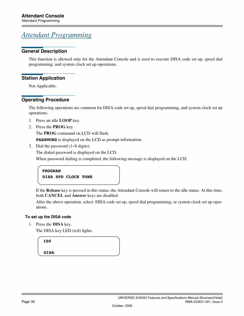
UNIVERGE SV8300 Features and Specifications Manual (Business/Hotel)Page 30 NWA-033631-001, Issue 2
October, 2008
Attendant ConsoleAttendant Programming
Attendant Programming
General Description
This function is allowed only for the Attendant Console and is used to execute DISA code set up, speed dialprogramming, and system clock set up operations.
Station Application
Not Applicable.
Operating Procedure
The following operations are common for DISA code set up, speed dial programming, and system clock set upoperations.
1. Press an idle LOOP key.
2. Press the PROG key.
The PROG command on LCD will flash.
PASSWORD is displayed on the LCD as prompt information.
3. Dial the password (1~8 digits).
The dialed password is displayed on the LCD.
When password dialing is completed, the following message is displayed on the LCD.
If the Release key is pressed in this status, the Attendant Console will return to the idle status. At this time,both CANCEL and Answer keys are disabled.
After the above operation, select: DISA code set up, speed dial programming, or system clock set up oper-ations.
To set up the DISA code
1. Press the DISA key.
The DISA key LED (red) lights.
PROGRAM
DISA SPD CLOCK TONE
ID#
DISA

UNIVERGE SV8300 Features and Specifications Manual (Business/Hotel)NWA-033631-001, Issue 2 Page 31
October, 2008
Attendant ConsoleAttendant Programming
2. Dial the ID code.
a. In the case of new ID code
b. In the case of existing ID code
The currently registered Pattern number is displayed and the number is blinking.
3. Dial the Pattern number (four digits).
If dial “9999”, the ID code is cleared.
4. Press the ANS key.
The Pattern number is blinking and the DISA codes are set up.
5. Press the CNCL key.
To set up another ID code, return to Step 2.
6. Press the CNCL key.
The system goes back to the status assumed after the password was set up.
To program system speed dialing
1. Press the SPD key.
The SPD key LED (red) comes on.
2. Dial the speed dial block # (5 digits).
The selected block number is displayed as follows along with the currently registered trunk access code andtelephone number.
PATTERN#
DISA
12345···55
PATTERN# 0100
DISA
12345···55
PATTERN# 0250
DISA
12345···55
PATTERN# 0250
DISA
12345···55
0 0 0 0 0
Tenant #Buffer #
12345. . . . . .56SPD
00012 9–
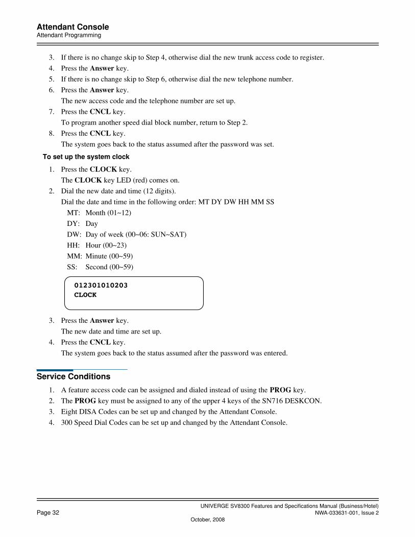
UNIVERGE SV8300 Features and Specifications Manual (Business/Hotel)Page 32 NWA-033631-001, Issue 2
October, 2008
Attendant ConsoleAttendant Programming
3. If there is no change skip to Step 4, otherwise dial the new trunk access code to register.
4. Press the Answer key.
5. If there is no change skip to Step 6, otherwise dial the new telephone number.
6. Press the Answer key.
The new access code and the telephone number are set up.
7. Press the CNCL key.
To program another speed dial block number, return to Step 2.
8. Press the CNCL key.
The system goes back to the status assumed after the password was set.
To set up the system clock
1. Press the CLOCK key.
The CLOCK key LED (red) comes on.
2. Dial the new date and time (12 digits).
Dial the date and time in the following order: MT DY DW HH MM SS
MT: Month (01~12)
DY: Day
DW: Day of week (00~06: SUN~SAT)
HH: Hour (00~23)
MM: Minute (00~59)
SS: Second (00~59)
3. Press the Answer key.
The new date and time are set up.
4. Press the CNCL key.
The system goes back to the status assumed after the password was entered.
Service Conditions
1. A feature access code can be assigned and dialed instead of using the PROG key.
2. The PROG key must be assigned to any of the upper 4 keys of the SN716 DESKCON.
3. Eight DISA Codes can be set up and changed by the Attendant Console.
4. 300 Speed Dial Codes can be set up and changed by the Attendant Console.
CLOCK012301010203

UNIVERGE SV8300 Features and Specifications Manual (Business/Hotel)NWA-033631-001, Issue 2 Page 33
October, 2008
Attendant ConsoleAttendant Training Jacks
Attendant Training Jacks
General Description
SN716 DESKCON provides two headset/handset jacks on the console, for training new operations.
Operating Procedure
Normal call handling procedures apply.
Service Conditions
When the jacks are used for training, both handsets can be used for listening and talking.

UNIVERGE SV8300 Features and Specifications Manual (Business/Hotel)Page 34 NWA-033631-001, Issue 2
October, 2008
Attendant ConsoleAudible Indication Control
Audible Indication Control
General Description
This feature allows the Attendant to adjust the volume of audible indications received at the Attendant Console.
Operating Procedure
Adjusting the volume control allows control of audible signaling at the Attendant Console.
Service Conditions
In SN716 DESKCON, the UP(↑) / DOWN(↓) key located on the right side of the console provides audible in-dication control, headset/handset receiver volume and LCD contrast adjustment.

UNIVERGE SV8300 Features and Specifications Manual (Business/Hotel)NWA-033631-001, Issue 2 Page 35
October, 2008
Attendant ConsoleCall Processing Indication
Call Processing Indication
General Description
This feature provides visual indications of all calls being processed or awaiting processing at the Attendant Con-sole.
Operating Procedure
No manual operation is required.
Service Conditions
1. Each Attendant Console is provided with 6 dedicated switching loop keys. Each loop key is associated withan LED to display the status of the call on that loop. The indicators may be on, off, or flashing, and greenor red.
2. When the Attendant Loop Release feature is activated, the status of the call is removed from the consoleuntil recalled by the Automatic Recall feature.
3. When the Attendant Console is calling a station, the LCD shows the called stations status (BSY, RST, PCK,FDA, FDN, FDB).
UNIVERGE SV8300 Features and Specifications Manual (Business/Hotel)Page 36 NWA-033631-001, Issue 2
October, 2008
Attendant ConsoleCall Queuing
Call Queuing
General Description
This feature provides the Attendant the ability to handle a series of exchange network calls in the order of theirarrival, (first in, first out) thereby eliminating unnecessary delays.
Operating Procedure
Press the Attendant Console ANSWER key to receive calls in the order of their queue position.
Service Conditions
1. Incoming calls arriving at the console will show “CW” on the LCD. Additionally, the “CW” flashes whena predetermined number of calls is in queue. This number is programmable from 1 to 48 on a system basis(the default is 6).
2. When an incoming call lights an Incoming Call Identification (LDN, ATND, RCL, WATS, FX, CCSA,etc.) LED, the Attendant may answer it out of the queuing sequence by pressing the indicated key.
3. Automatic Call Distribution is not used in Multiple Console Operation. All incoming call indications appearat each console within the same tenant group so that the call can be answered by any console. Each consoleshares the same queue.
4. An incoming call cannot be answered simultaneously by more than one Attendant. Only the Attendant thatpressed the ANSWER key first is connected to the call. The other Attendant's ANSWER key will pick upthe next call or be ineffective (no queue) when pressed.
5. If a power failure occurs, calls in queue that have the power failure transfer feature associated with theirtrunk will be connected to power failure stations. Other calls in queue will not be connected to power failurestations.
6. When the system is changed from day to night mode, calls already waiting in the queue will remain in thesame queue and can be answered by the Attendant Console.
7. Calls in queue can overflow to Night Service. Refer to Attendant Overflow Features and Specifications formore information.

UNIVERGE SV8300 Features and Specifications Manual (Business/Hotel)NWA-033631-001, Issue 2 Page 37
October, 2008
Attendant ConsoleCall Splitting
Call Splitting
General Description
This feature allows the Attendant to confer privately with one party on an Attendant handled connection withoutthe other party overhearing.
Operating Procedure
To speak with the called party only
1. Dial the desired station number.
2. The Station class/number is displayed.
3. Wait for the party to answer.
To speak with calling party only
1. Press the SRC key.
2. The Trunk kind/number displayed.
3. Proceed with the conversation.
To return to called party
1. Press the DEST key.
2. The Station class/number displayed.
To speak with both parties
Press the TALK key.
To release from the Attendant Console
Press the RLS key.
To disconnect all parties involved in a three-way Conference
1. Press the DEST key.
2. Press the CANCL key twice.
Service Conditions
1. The Attendant may alternate between the called and calling station parties, and three-party Conference, asdesired.
2. The Call Splitting feature is a standard Attendant feature.
3. Call Splitting is automatic when the Attendant begins call completion or answers a recall.
4. Call Splitting is manual when the SRC, DEST, or TALK key is pressed on the Attendant Console.

UNIVERGE SV8300 Features and Specifications Manual (Business/Hotel)Page 38 NWA-033631-001, Issue 2
October, 2008
Attendant ConsoleCall Waiting Display
Call Waiting Display
General Description
This feature provides a visual indication to the Attendant when one or more calls are waiting to be answered.
Operating Procedure
No manual operation is required.
Service Conditions
1. When there are any incoming calls to the Attendant Console that have not yet been answered, the CW (CallWaiting) will show on the LCD (without flashing). A value of from 1 to 48 (the default is 6) waiting callscan be set to start the CW flashing, on a per-system basis.
The number of waiting calls (1 to 96 calls) will show besides CW on the LCD.
2. When multiple consoles are installed, the CW will show on the displays of all consoles that are assigned tothe same tenant group. Other tenant group consoles will reflect the call waiting status for their tenant grouponly.
3. The following types of unanswered incoming calls to an Attendant Console are counted as calls waiting:
• LDN (Listed Directory Number Calls)
• ATND (Attendant Dial 0 Calls)
• RCL (Attendant Recall Calls)
• FX (Foreign Exchange Calls)
• WATS (Wide Area Telephone Service Calls)
• TIE (Tie Line Calls)
• BUSY (Call Forwarding - Busy Line Calls to Attendant)
• NANS (Call Forwarding - No Answer Calls to Attendant)
• TF (Interposition Transfer/Calling Calls between Attendants)
• ICPT (Call Forwarding - Intercept Calls)
• ALL (Call Forwarding - All Calls to Attendant)
• CCSA (Common Channel Signaling Arrangement Calls)
4. An audible indication will be provided when the CW is shown, unless the Attendant is already on a loop orunless the volume control is used to silence the buzzer. Off-hook ringing is available on a per-console basis.

UNIVERGE SV8300 Features and Specifications Manual (Business/Hotel)NWA-033631-001, Issue 2 Page 39
October, 2008
Attendant ConsoleCommon Route Indial
Common Route Indial
General Description
This feature allows assignment of incoming DID calls to different Attendant Call Selection keys based on thelast 4 digits dialed into the system. Up to eight individual Listed Directory Numbers can be assigned in systemprogramming. When an incoming call to any of these trunks is received, an Attendant Call Selection key willflash and the LCD will indicate the Listed Directory Number associated with that trunk route.
Operating Procedure
Refer to Attendant Call Selection Features and Specifications.
Service Conditions
1. A maximum of one Listed Directory Number can be specified for each Attendant Call Selection key. Up toeight LDN keys may be assigned.
2. This feature can help identify calls to particular tenants who are sharing Attendant(s). In this case, serviceconditions for Tenant Service would apply to the system.
3. If the system or tenant group is in night mode, the Common Route Indial lines would follow the establishednight rerouting.
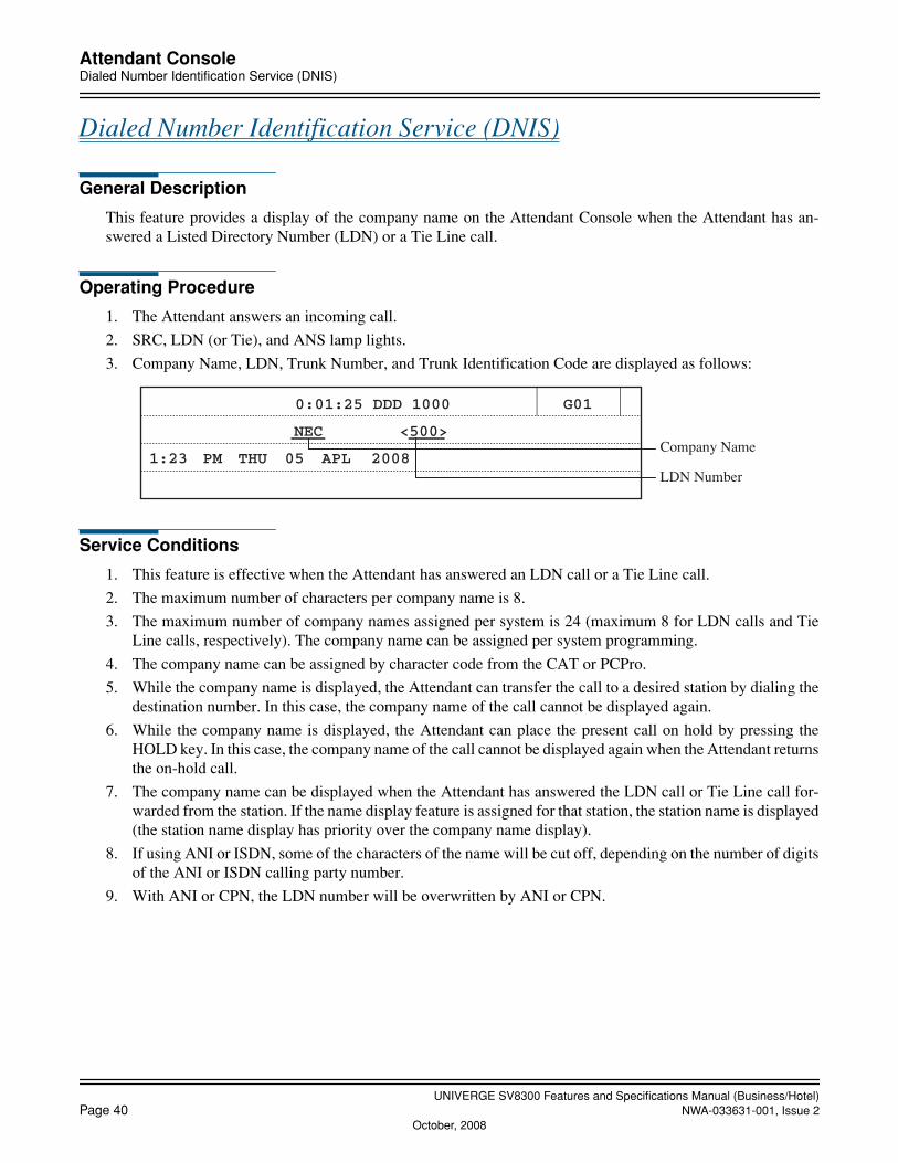
UNIVERGE SV8300 Features and Specifications Manual (Business/Hotel)Page 40 NWA-033631-001, Issue 2
October, 2008
Attendant ConsoleDialed Number Identification Service (DNIS)
Dialed Number Identification Service (DNIS)
General Description
This feature provides a display of the company name on the Attendant Console when the Attendant has an-swered a Listed Directory Number (LDN) or a Tie Line call.
Operating Procedure
1. The Attendant answers an incoming call.
2. SRC, LDN (or Tie), and ANS lamp lights.
3. Company Name, LDN, Trunk Number, and Trunk Identification Code are displayed as follows:
Service Conditions
1. This feature is effective when the Attendant has answered an LDN call or a Tie Line call.
2. The maximum number of characters per company name is 8.
3. The maximum number of company names assigned per system is 24 (maximum 8 for LDN calls and TieLine calls, respectively). The company name can be assigned per system programming.
4. The company name can be assigned by character code from the CAT or PCPro.
5. While the company name is displayed, the Attendant can transfer the call to a desired station by dialing thedestination number. In this case, the company name of the call cannot be displayed again.
6. While the company name is displayed, the Attendant can place the present call on hold by pressing theHOLD key. In this case, the company name of the call cannot be displayed again when the Attendant returnsthe on-hold call.
7. The company name can be displayed when the Attendant has answered the LDN call or Tie Line call for-warded from the station. If the name display feature is assigned for that station, the station name is displayed(the station name display has priority over the company name display).
8. If using ANI or ISDN, some of the characters of the name will be cut off, depending on the number of digitsof the ANI or ISDN calling party number.
9. With ANI or CPN, the LDN number will be overwritten by ANI or CPN.
0:01:25 DDD 1000 G01
NEC <500>
1:23 PM THU 05 APL 2008
Company Name
LDN Number
UNIVERGE SV8300 Features and Specifications Manual (Business/Hotel)NWA-033631-001, Issue 2 Page 41
October, 2008
Attendant ConsoleIncoming Call Identification
Incoming Call Identification
General Description
Incoming calls are identified by various means. Refer to Attendant Called/Calling Number, Attendant Call Se-lection, Attendant Source Key, Attendant Listed Directory Number and Common Route Indial Features andSpecifications.
Operating Procedure
Normal operating procedures are applied for each feature.
Service Conditions
Refer to the applicable Features and Specifications.
UNIVERGE SV8300 Features and Specifications Manual (Business/Hotel)Page 42 NWA-033631-001, Issue 2
October, 2008
Attendant ConsoleIndividual Trunk Access
Individual Trunk Access
General Description
The Attendant Console is provided with the ability to access each individual trunk by dialing an associated iden-tification code. This allows detection of faulty trunks during regular testing or after complaints. The CustomerAdministration Terminal (CAT) or PCPro has the capability to then busy-out the trunk until repair is effected.
Operating Procedure
1. The Attendant presses an idle LOOP key.
2. The Attendant dials the Individual Trunk access code.
3. The Attendant dials the Individual Trunk identification code.
4. If the trunk was idle, testing can follow.
Service Conditions
1. The Attendant Console LCD will show the individual trunk identification code.
2. If the trunk is busy, the attendant receives busy tone.
3. If the trunk has been set to busy out status by the CAT or PCPro, the Attendant can still access the trunk.
4. Individual Trunk Access is not available for ISDN PRI lines.
UNIVERGE SV8300 Features and Specifications Manual (Business/Hotel)NWA-033631-001, Issue 2 Page 43
October, 2008
Attendant ConsoleMulti-Function Key
Multi-Function Key
General Description
This feature allows the top row of keys on the Attendant Console to perform and display multiple functions inaccordance with the status of call processing.
Operating Procedure
No manual operation is required.
Service Conditions
1. Multi-Function Keys can be assigned to key numbers 01-04 (SN716 DESKCON) located directly below theLCD.
2. The lowest line of the LCD displays the function of the associated Multi-Function key under the followingconditions:
• Idle state
• When an attendant-called station answers or the attendant seizes an originating trunk
• When the called station is busy
• When the called station is in Do Not Disturb
• When dialing a station number without pressing the LOOP key: Hotel/Motel features will be activated
3. A maximum of 5 status functions per Multi-Function Key can be assigned.
4. The LEDs associated with the Multi-Function keys indicates the status of the functions displayed on theliquid crystal displays (LCD).
5. The Incoming Call Identification (ICI) and LOOP keys should not be assigned as Multi-Function keys.

UNIVERGE SV8300 Features and Specifications Manual (Business/Hotel)Page 44 NWA-033631-001, Issue 2
October, 2008
Attendant ConsoleMultiple Console Operation
Multiple Console Operation
General Description
This feature allows more than one Attendant Console to operate within the same system.
Operating Procedure
Normal operating procedures are applied for each console installed.
Service Conditions
1. The maximum number of consoles allowable per system is 8.
2. Each incoming call is displayed on all consoles within a tenant group whether idle or busy. If all Attendantsare involved in processing calls when another C.O. call arrives, the CW (Call Waiting) will show on all con-sole LCDs.
3. A station can be connected to only one Attendant loop at a time. Any attempt at establishing multiple con-nections will result in reorder tone being sent to the party attempting multiple loop connection.
4. Attendant Interposition Transfer is used to transfer calls between Attendant Consoles.
5. The system operates only on a switched-loop basis. Fixed-loop operation is not available.
6. To place a multiple console system (or a multiple console tenant group) into Night Service, a programmedmaster console must press Night key for SN716 DESKCON. If one of the other consoles enters Night Ser-vice, all calls addressed to that console will be directed to the other console(s).
7. When a console has entered Night Service, all calls already connected to its loop must be processed fromthat console. Recalls and serial recalls are routed to the night transfer station, if assigned.
UNIVERGE SV8300 Features and Specifications Manual (Business/Hotel)NWA-033631-001, Issue 2 Page 45
October, 2008
Attendant ConsolePushbutton Calling - Attendant Only
Pushbutton Calling - Attendant Only
General Description
This feature permits an operator to place all calls over Dual-Tone, Multi-Frequency (DTMF) lines from thepush-button keypad on the Attendant Console.
Operating Procedure
The operator presses the push-button keypad to dial.
Service Conditions
1. This feature requires that all Central Office trunks or tie trunks accept push-button signaling (DTMF).
2. Push-button Calling- Attendant Only may be added to the system without providing push-button calling ca-pability to other stations.

UNIVERGE SV8300 Features and Specifications Manual (Business/Hotel)Page 46 NWA-033631-001, Issue 2
October, 2008
Attendant ConsoleSerial Call
Serial Call
General Description
This feature is activated by the Attendant when an incoming calling party wishes to speak with more than oneinternal party. When the internal station subsequently disconnects from the Analog CO Line call, the C.O. partyautomatically rings back to the same Attendant.
Operating Procedure
1. The Attendant answers an incoming C.O. call.
2. The Attendant extends the call to the desired station.
3. The Attendant presses the SERIAL CALL SET (SC) key.
4. The called station and incoming caller are connected.
5. The called station hangs up. The Serial Call Termination (SRL) LED on the Attendant Console flashes at60 IPM. If the Attendant is available, an audible indication is provided.
6. The Attendant presses the ANS or SRL key to return to the original incoming calling party.
Service Conditions
1. Serial Calling is not provided for Station-to-Station calling.
2. Serial Calling can be enabled or disabled on a per-console basis.
3. This feature is not available for tandem connections.
4. Serial Calling is allowed when a station is involved in an Attendant Conference.
5. No features are denied toward a line or trunk involved in a Serial Call.

UNIVERGE SV8300 Features and Specifications Manual (Business/Hotel)NWA-033631-001, Issue 2 Page 47
October, 2008
Attendant ConsoleTime Display
Time Display
General Description
This feature provides a digital time display on the Attendant Console LCD.
Operating Procedure
Time is constantly displayed on the Attendant Console LCD.
Service Conditions
The clock display of the Attendant Console is synchronized with the clock in the system.

UNIVERGE SV8300 Features and Specifications Manual (Business/Hotel)Page 48 NWA-033631-001, Issue 2
October, 2008
Attendant ConsoleTrunk Group Busy Display
Trunk Group Busy Display
General Description
A visual indication is supplied to the Attendant when all trunks in a particular trunk group are busy.
Operating Procedure
No manual operation is required.
Service Conditions
1. The Attendant Console must be programmed to have a designated Trunk Group Busy LED on a functionkey.
2. This feature may be used on trunk groups consisting of either DDD, DID, WATS, Tie, FX, or special trunks.
3. Besides Trunk Group Busy LEDs on the Attendant Console, Trunk Group Busy status can be displayed onthe following LEDs:
• Function key LEDs on Multiline Terminals.
4. A total of 62 Trunk Group Busy LEDs are available for Attendant Consoles, Multiline Terminals or Exter-nal LEDs.
UNIVERGE SV8300 Features and Specifications Manual (Business/Hotel)NWA-033631-001, Issue 2 Page 49
October, 2008
Attendant ConsoleUnsupervised Trunk-to-Trunk Transfer By Attendant
Unsupervised Trunk-to-Trunk Transfer By Attendant
General Description
This feature allows an Attendant to transfer an incoming or outgoing call on one trunk to an outgoing trunk andexit the connection before the called party answers.
Operating Procedure
1. An incoming call is received and answered in the normal manner. The trunk number is displayed.
2. The Attendant dials the access code of the outgoing route, then the destination number. The dialed digitsare displayed.
3. If the feature is allowed, the display will change to show the selected outgoing trunk number.
4. The call is extended (by operation of the RELEASE key). The Attendant Console will be recalled. On an-swer, the Attendant will be connected to the original trunk party. If the call is answered, the trunk-to-trunkconnection is maintained.
5. After calling the Attendant Console again, the called party may answer. This would result in an initial three-way conversation before the call is extended. Alternately, the Attendant can re-extend the call (from above)to the same destination or extend it to another.
Service Conditions
1. The feature is dependent on trunk supervision and other conditions being met.
2. The trunk associated with at least one side of the call must be programmed for answer and/or release super-vision to ensure that the trunks do not lock up or this feature will be disallowed.

UNIVERGE SV8300 Features and Specifications Manual (Business/Hotel)Page 50 NWA-033631-001, Issue 2
October, 2008
Attendant Delay Announcement
Attendant Delay Announcement
General Description
This feature provides an announcement, via a Built-in Voice Response System (VRS), to external calls that arenot answered by the attendant within a predetermined time.
Note: In the Built-in VRS, messages are stored on an internal memory of the CPU blade in Unit #1 (CPU #1).No VM daughter board (PZ-VM21) is required.
Station Application
Not applicable.
Operating Procedure
No manual operation required.
Service Conditions
1. Up to eight calls can be connected to one VRS circuit at one time.
2. This feature is provided on a trunk-route basis (C.O./Tie/DID).
3. A maximum of 8 VRS circuits can be assigned on a tenant/system-basis.
4. The maximum duration for the announcement is 30 seconds.
5. No answer timer to start playing the announcement is programmable from 4 to 120 seconds in 4 second in-crement. Note that this timer is commonly used with the Delay Announcement - ACD/UCD feature.
6. The announcement can be supplied to a call once or several times, periodically. (This is selectable).If programmed to the periodic announcement, Music On Hold is provided between the announcements. Thetime between the announcements is programmable from 4 to 120 seconds in 4 second increment. Note thatthis timer is commonly used with the Delay Announcement - ACD/UCD feature.
7. Calls remain queued to the attendant until answered or until remote-disconnect signalling occurs.
8. When both Attendant Overflow and Attendant Delay Announcement are programmed, following servicepriority is applied: Priority #1: Attendant Overflow (an overflow to an outside station) Priority #2: Attendant Delay Announcement Priority #3: Attendant Overflow (a change to Night Service)
9. Incoming call billing to the outside party starts when the announcement begins.

UNIVERGE SV8300 Features and Specifications Manual (Business/Hotel)NWA-033631-001, Issue 2 Page 51
October, 2008
Attendant Lockout
Attendant Lockout
General Description
This feature denies an Attendant the ability to re-enter an established trunk or station connection without beingrecalled by that station after the call is put in consultation hold.
Station Application
Attendant Consoles.
Operating Procedure
No manual operation is required.
Service Conditions
1. This feature is mutually exclusive with the Attendant Override feature.
2. The Attendant Override feature must be disabled to enable this feature.
UNIVERGE SV8300 Features and Specifications Manual (Business/Hotel)Page 52 NWA-033631-001, Issue 2
October, 2008
Attendant Overflow
Attendant Overflow
General Description
When an incoming call, which has terminated from a trunk to the Attendant Console, remains unanswered aftera predetermined time period, this feature provides a change to Night Service for that particular trunk, or an over-flow to an outside trunk.
Station Application
Attendant Consoles.
Operating Procedure
No manual operation is required.
Service Conditions
1. Either a change to Night Service or an overflow to an outside station can be selected by system program-ming. If both features are programmed, an overflow to an outside station has priority over a change to NightService.
2. The Night Service assignment applied to the unanswered call is the same that applies to that trunk when thesystem is placed in night mode.
3. This feature only applies to incoming calls on Loop Start or Ground Start trunks, and is provided on a persystem basis.
4. The activation timing for this feature is, by default, from 32 to 36 seconds after the call status has changedfrom trunk incoming call to Attendant call, and can be programmed from 4 seconds to 120 seconds in in-crements of 4 seconds.
5. When the destination of the Night Service is specified as a Direct Inward Termination (DIT), the incomingcall processing is changed to Trunk Answer Any Station (TAS) when the called DIT station fails to answerthe rerouted call within a predetermined time period.
6. The next incoming trunk call will ring at the Attendant Console as normal.
7. An overflow to an outside station is realized by assigning virtual station number and setting Call Forward-ing - Outside for that virtual station.If the overflow destination is not assigned, the incoming caller is not forwarded and the Attendant Consoleis kept calling.
8. When an overflow to an outside station encounters outgoing trunks that are all busy, the Attendant Consolecontinues to call.
9. When an outside destination station is busy, a caller will hear Busy Tone. And when an outside destination station does not answer, it will be kept calling.
10. When both Attendant Overflow and Attendant Delay Announcement are programmed, following servicepriority is applied: Priority #1: Attendant Overflow (an overflow to an outside station) Priority #2: Attendant Delay Announcement Priority #3: Attendant Overflow (a change to Night Service)

UNIVERGE SV8300 Features and Specifications Manual (Business/Hotel)NWA-033631-001, Issue 2 Page 53
October, 2008
Attendant Override
Attendant Override
General Description
This feature permits an Attendant to enter a busy connection (station or trunk) using the Attendant Console.When this feature is activated, a warning tone is sent to the connected parties after which they are connectedwith the Attendant in a three-way bridge.
Station Application
Attendant Consoles.
Operating Procedure
To activate Attendant Override
1. Press an idle LOOP key.
2. Dial the desired station number or dial the feature access code for individual trunk access and the desiredtrunk number.
3. Press the BV key when busy tone is heard.
4. A double burst tone is sent to the connected parties.
5. The Attendant may now monitor or join the conversation.
ORPress the RELEASE key to disengage.
Service Conditions
1. This feature may be used to enter trunk-to-trunk, station-to-station, or station-to-trunk connections.
2. Each tone burst is 0.08 seconds in duration, and is provided to both parties connected.
3. Attendant Override of a busy station is denied if the busy station is dialing, talking to another Attendant,receiving a system generated tone, protected against any override by DND key, or if any of the followingfeatures are in progress:
• Attendant Camp-On• Call Forwarding• Call Transfer• Conference• Data Communications• Data Line Security• Executive Override• Hold• Paging• Privacy• Station Hunting• Voice Call
4. The Attendant can override a station that is part of an Automatic/Uniform Call Distribution group.

UNIVERGE SV8300 Features and Specifications Manual (Business/Hotel)Page 54 NWA-033631-001, Issue 2
Authorization Code
Authorization Code
General Description
An Authorization Code is a numerical code that will temporarily change a station’s Class of Service to a Classof Service assigned to that Authorization Code. This new Class of Service allows access to trunks, dialing pat-terns, and/or features that would otherwise be restricted.
Station Application
All stations.
Operating Procedure
Procedure 1
1. Lift handset and receive dial tone.
2. Enter the feature access code for Authorization Code.
3. Enter the Authorization Code.
4. Receive dial tone.
5. Enter the number to be called or access the desired feature.
orProcedure 2
1. Lift the handset and receive dial tone.
2. Dial LCR access code and desired number. If the call is restricted by toll restriction, receive feature dialtone.
3. Dial Authorization Code, and the call is originated.
Service Conditions
Service Conditions on Procedure 1 & 2
1. The feature access code for Authorization Code can be 1 to 4 digits.
2. Authorization Code Limitations
• Number of digits: 1 digit-16 digits
However, up to 10-digit code is allowed in the following case:
- When Authorization Code is controlled by Open Application Interface (OAI)
- When Authorization Code is output to a Station Message Detail Recording (SMDR) or Hotel Prop-erty Management System (PMS)
• Number of codes:The maximum number of codes depends on the numbering scheme and digit number.The maximum number of Code Development table in the system: 3072

UNIVERGE SV8300 Features and Specifications Manual (Business/Hotel)NWA-033631-001, Issue 2 Page 55
Authorization Code
The maximum number of codes is as follows according to the formula below*:
* 111 + (Number of digits -3) x Number of codes ≤ 3072
3. Authorization Codes are assigned in system data from the PCPro or the Customer Administration Terminal(CAT).
4. Authorization Code changes the Class of Service for that call only.
5. If the system is designated as KF Registration, this feature will not be available.
6. An Authorization Code can be assigned per a station number so that one code is used only on the specificstation.
Service Conditions on Procedure 2
1. This feature can work with LCR origination (cannot work with route origination).
2. Originating terminals are Multiline Terminal, Single Line Telephone or PHS/PCS Personal Station (PS).
3. Feature dial tone is set at the following timing: after dialing the maximum number of digits / when time-outoccurs after dialing the number/ when dialing “#” to complete the dialing.
4. Feature dial tone is sent if the call is restricted by the toll restriction. If it is not restricted, the call is origi-nated normally.
5. Procedure 2 is available in the following cases:
a. During a station/trunk is placed on consultation hold
b. Outgoing call by Last Number Redial (Redial key + #)
c. Outgoing call by System Speed Dial or Station Speed Dial
d. Outgoing call by One Touch Key
6. If the toll restriction class for the calling party is higher than the one after dialing the Authorization code,the outgoing call is restricted and the calling party will hear Reorder Tone.
7. A station under Room Cut Off, Special Dial Tone is received after the calling station will hear feature dialtone after the desired number is dialed, but the call is restricted after entering the Authorization code andthe calling station will hear Reorder Tone.
8. Outgoing ISDN calls by Trunk Direct Appearance cannot be made by this feature.
9. When a station under toll restriction sets Call forwarding-Outside, the call to that station can not be forward-ed by this feature.
Number of digits 4 5 6 7 8 9 10 16
Number of codes 2961 1480 987 740 592 493 423 227

UNIVERGE SV8300 Features and Specifications Manual (Business/Hotel)Page 56 NWA-033631-001, Issue 2
Automated Attendant
Automated Attendant
General Description
This feature allows the system to answer incoming trunk calls. The system will supply a message and/or dialtone to the caller. The caller can then dial the desired extension number and be directed to that station.
Station Application
Not applicable.
Operating Procedure
To record a message
1. Lift the handset or press the Bold key and receive dial tone.
2. Dial the VRS record access code and the VRS message number (0-7). Three seconds of tone will be sup-plied.
3. Record the message (maximum duration - 30 seconds).
4. Restore handset.
To replay a message
1. Lift the handset or press the Bold key and receive dial tone.
2. Dial the VRS replay access code and VRS message number (0-7).
3. Receive the message.
4. Restore handset.
To delete a message
1. Lift the handset or press the Bold key and receive dial tone.
2. Dial the VRS delete access code and VRS message number (0-7).
3. Receive service set tone.
4. Restore handset.
Service Conditions
1. If the called station is busy or does not answer, or the number dialed is a feature access code or trunk accesscode, any one of the following operations can be set:
• The incoming trunk call can be released
• A 2nd message and dial tone, or dial tone, can be supplied
• An alternate call terminating destination (Attendant, Trunk Answer Any Station, Direct Inward Termi-nation) can be provided.
The no answer timer is programmable from 4 to 120 seconds in 4 second increment.
UNIVERGE SV8300 Features and Specifications Manual (Business/Hotel)NWA-033631-001, Issue 2 Page 57
Automated Attendant
2. Dual-Tone Multi-Frequency (DTMF) digits must arrive within a predetermined time interval (14 seconds)after the message is supplied. If they do not, the system will transfer, as per programming, to an alternatecall terminating destination (Attendant Console, Trunk Answer Any Station, Direct Inward Termination).
3. Call Forwarding, Station Hunting, Call Pickup and Automatic/Uniform Call Distribution features are all ef-fective after the call has been directed.
4. This feature uses the DTMF receivers of the system. Therefore, the total number of DTMF receivers avail-able in the system is reduced proportionately by Automated Attendant usage.
• Up to 48 DTMF receivers per Unit (including Caller ID receivers, Caller ID senders and MF receivers)
• Up to 64 DTMF receivers per system
5. A DTMF receiver must be available before the Automated Attendant can answer. When there is an incom-ing call and all DTMF receivers are busy, the connection to the Automated Attendant is attempted every 4seconds until an idle DTMF receiver is found. Ringback tone from the C.O. is supplied to the calling partyuntil the Automated Attendant answers.
6. Automated Attendant is assigned to trunks on a per tenant and per trunk basis.
7. When the calling party cannot send DTMF digits, any one of the following operations can be selected inprogramming:
• The trunk can be released.
• An alternate call terminating destination (Attendant, Trunk Answer Any Station, Direct In Termination)can be provided.
8. When the called party is busy or does not answer, and all DTMF receivers are busy, then the following op-erations can be selected in programming:
• The trunk can be released.
• An alternate call terminating destination (Attendant or Trunk Answer Any Station) can be provided.
9. Automated Attendant cannot call out of the system. It can only answer incoming calls to the PBX for whichit is programmed.
10. Automated Attendant cannot transfer calls over CCIS to another NEC PBX.
11. The message can be changed by DAY/NIGHT mode. If programmed so, the 2nd announcement option can-not be used when the called station is busy or does not answer, or the number dialed is restricted (ServiceCondition #1).
12. The message replay is up to 30 seconds at both first announcement and second announcement. Therefore,the message should be recorded within 30 seconds on the Bulit-in Voice Response System (VRS).
13. Single connection to the announcement is made in this application. More than one VRS port can be useddepending on traffic condition. In the Built-in VRS, up to 8 messages can be provided per system for allannouncement features. The messages are stored on the internal memory of the CPU blade of Unit #1 (CPU#1).
UNIVERGE SV8300 Features and Specifications Manual (Business/Hotel)Page 58 NWA-033631-001, Issue 2
Automatic Call Distribution (ACD)
Automatic Call Distribution (ACD)
General Description
The Automatic Call Distribution (ACD) feature permits incoming calls to terminate to a prearranged group ofstations. Calls are distributed in the order of arrival to idle terminals within the group, based on which terminalhas been idle the longest period of time. Stations may log on/log off from the ACD group. Supervisor stationsmay monitor conversations of agents.
Station Application
Multiline and single-line stations.
Operating Procedure
Refer to individual ACD sub-features for details on station operating procedures.
Service Conditions
1. A maximum of 16 ACD groups can be assigned per system. Each ACD group is assigned a pilot number.Calls directed to the pilot number are directed to that ACD group.
2. The maximum number of stations in an ACD group is 60. The maximum number of ACD groups in thesystem is 16. The total number of ACD stations may not exceed the system limits of 1,024 stations. IfACD-MIS is used, the maximum number of ACD stations is 60.
3. Assignment of ACD groups is performed from the PCPro or Customer Administration Terminal (CAT).
4. ACD groups consist of a pilot station and one or more member stations. Hunting is initiated in a circularfashion, and then based on which member has been idle the longest period of time.
5. If all stations within the ACD group are busy, incoming calls may be serviced in the following ways:
• remain in queue until an agent becomes available (Ringback Tone provided)
• immediately overflow to another group, to a station, or to the Attendant
• remain in queue until an agent becomes available (Delay Announcement or Music on Hold provided)
• remain in queue for a preset time (Ringback Tone, Delay Announcement, or Music on Hold provided),then overflow to another group, to a station, or to the Attendant.
6. When the pilot station has set Call Forwarding – All Calls, incoming calls to the ACD group will be trans-ferred to the destination of that Call Forwarding – All Calls setting.
7. An ACD group number can be used as the destination station of Direct Inward Termination (DIT), or as adesignated Night Service station.
8. An ACD group number can be assigned as the destination station of Off-Hook Alarms, Priority Calls, andAttendant Night Transfer.
9. ACD group pilot numbers should not be placed in Station Hunting groups. The Station Hunting featurewould take priority over the ACD function.
10. Two types of traffic measurements can be provided for ACD:
a. ACD group Peg Count
UNIVERGE SV8300 Features and Specifications Manual (Business/Hotel)NWA-033631-001, Issue 2 Page 59
Automatic Call Distribution (ACD)Busy In/Busy Out - ACD
• Count of incoming calls
• Count of answered calls
• Count of abandoned calls
• Count of waiting calls
• Count of all busy calls
b. ACD station Peg count
• Count of answered calls
11. Upon initial installation, or after a system initialization (reset), each agent must lift and restore handset (oftheir station) to begin receiving calls for the ACD group.
Busy In/Busy Out - ACD
General Description
This feature allows an agent in an ACD group to log their station into or out of the group. This allows the systemto control whether a call directed to the pilot number of the ACD group goes to that station or not. This preventsincoming calls from being directed to stations at which no agent is available.
Station Application
Multiline Terminals and Single Line Stations.
Operating Procedure
To log off (busy out) an ACD station
1. Lift the handset and receive extension dial tone.
2. Dial the log off (busy out – set) feature access code, or press the LOG OFF key.
3. Restore the handset.
To log on (cancel busy out) an ACD station
1. Lift the handset and receive extension dial tone.
2. Dial the log on (busy out – cancel) feature access code, or press the LOG ON key.
3. Restore the handset.
Service Conditions
1. Any agent may log on/off. When an agent has activated log off, any call targeted at the ACD group willbypass that agent. Calls directed to the specific station number will ring at the agent position.
2. The agent may originate calls while in log off mode.
3. The agent can log off their station while idle, or while on an incoming outside call. When that call is com-pleted, the station is logged off.
4. The agent can log on/off from the secondary extension by dialing the log on/off feature access code. TheLOG ON/LOG OFF key is not available for the secondary extension.

UNIVERGE SV8300 Features and Specifications Manual (Business/Hotel)Page 60 NWA-033631-001, Issue 2
Automatic Call Distribution (ACD)Call Waiting Indication - ACD
Call Waiting Indication - ACD
General Description
This feature provides a visual indication when an incoming call to an ACD group is placed in queue, due to an“all agents busy” condition. An external relay controlled indicator or an LED on a Multiline Terminal can beused to provide Call Waiting Indication.
Station Application
Multiline Terminals assigned with a Call Waiting (CW) Lamp
Operating Procedure
No operating procedure is necessary. Indication is automatic, once it is assigned.
Service Conditions
1. A 2PGDAD module with a DLC blade, or a built-in relay circuit of the CPU blade is required to providethe external relay control when an external indicator is used.
2. There is no limit to the number of appearances of a CW lamp assigned to Multiline Terminals. One CWlamp per group is available.
3. On a per system basis, the option is available to select how many calls in queue causes the CW lamp to flash.Default setting is one. The LED lights steadily until the set threshold count is reached, at which time theLED begins to flash.)
4. Provision of ringing on a CW key is controlled on a per station basis.
5. The interruption rate of the external relay control is programmable, on a per system basis, as follows:
• 30 IPM
• 60 IPM
• 120 IPM
• Steady
This interruption rate is the same as the rate used for Trunk Answer Any Station (TAS).

UNIVERGE SV8300 Features and Specifications Manual (Business/Hotel)NWA-033631-001, Issue 2 Page 61
Automatic Call Distribution (ACD)Delay Announcement - ACD
Delay Announcement - ACD
General Description
This feature allows the system to provide a recorded announcement to an incoming caller placed in queue to anACD group. A single announcement, or two separate announcements, can be provided.
Station Application
None.
Operating Procedure
Operation is automatic, once system programming is assigned.
Service Conditions
1. A Delay Announcement service can be provided for DIT, DID or a trunk call transferred by a station useror the Attendant to an ACD Group. Internal calls or station-to-station transferred calls to the ACD Groupcan go into the ACD queue but do not receive the Delay Announcement.
2. The following configurations are available when using Delay Announcement:
a. After being in queue for a predetermined time, the caller receives a Delay Announcement, followed by Music-on-Hold (if provided), until an agent is available or the caller hangs up.
b. After being in queue for a predetermined time, the caller receives a Delay Announcement, followedby Music-on-Hold (if provided) for a programmed interval, then followed by repetition of the DelayAnnouncement. This process repeats until an agent in the ACD group is available on the caller hangsup.
c. After being in queue for a predetermined time, the caller receives a first Delay Announcement,followed by Music-on-Hold (if provided). After a programmed interval, the caller then hears a secondDelay Announcement, followed again by Music-on-Hold. The second Delay Announcement andMusic-on-Hold are then repeated at the programmed interval time until an agent becomes available orthe caller hangs up.
d. After being in queue for a predetermined time, the caller receives a first Delay Announcementfollowed by Music-on-Hold (if provided). After a pre-determined interval time, the system checks tosee if an overflow destination has been assigned for the incoming trunk route. If assigned, and thedestination is available (idle), the call overflows to the destination. If not assigned, or the destinationis busy, the call remains in queue for the predetermined interval time and the system then checksagain for overflow assignment. For the latter case, if repetition of first announcement is set, or asecond announcement is made available, that announcement will be played.
Note: Repeat of the first announcement or receipt of second announcement is only available when the overflow des-tination for the trunk route is busy (not available).
3. Overflow out of queue causes the caller to be removed from the queue. This means that if the overflow des-tination (out of queue) is another ACD group, the caller is placed at the end of that queue (if all agents arebusy) and is no longer in queue for the first group.

UNIVERGE SV8300 Features and Specifications Manual (Business/Hotel)Page 62 NWA-033631-001, Issue 2
Automatic Call Distribution (ACD)Delay Announcement - ACD
4. One Voice Response System (VRS) circuit is required for each Delay Announcement. CPU includes twoVRS circuits.
5. One Voice Response System (VRS) circuit is required for each Delay Announcement. Up eight VRS mes-sages can be assigned per system including other announcement features. The maximum duration for theannouncement is 30 seconds. The messages are stored on an internal memory of the CPU blade in Unit #1(CPU #1).
6. The call waiting time before the first Delay Announcement is programmable from 4 to 120 seconds in 4second increment. Note that this timer is commonly used with the Attendant Delay Announcement feature.
7. The time between the announcements is programmable from 4 to 120 seconds in 4 second increment. Notethat this timer is commonly used with the Attendant Delay Announcement feature.
8. Delay Announcements cannot be shared between groups. Each group must have their own set of Delay An-nouncements.
9. Up to eight calls can be connected to one VRS circuit at one time. Multiple VRS circuits may be assignedfor 1st or 2nd Delay Announcement function to the same ACD group, when warranted by high traffic ratesinto the group.
10. When an ACD station becomes available, the caller is immediately connected to the station, even if the re-corded announcement is in progress.
11. Incoming call billing to the outside party starts when the first recorded announcement begins.
12. Calls remain queued to the ACD group until the agent is answered or until remote-disconnect signaling oc-curs.

UNIVERGE SV8300 Features and Specifications Manual (Business/Hotel)NWA-033631-001, Issue 2 Page 63
Automatic Call Distribution (ACD)Hunt Past No Answer - ACD
Hunt Past No Answer - ACD
General Description
This feature allows calls targeted at an ACD group to hunt past an agent’s station after a no answer condition ifthe agent forgets to log out of the group and does not answer the call.
Station Application
Multiline Terminals and Single Line Stations.
Operating Procedure
Refer to the Call Forwarding - No Answer Features and Specifications for details on setting the No Answer for-warding condition.
Service Conditions
1. This feature uses Call Forwarding - No Answer (to another ACD member) to enable a call to an agent thatfails to answer, to hunt past that agent, to the next agent.
2. Calls directed to the agent’s primary extension number will also forward (on a no-answer condition) to thenext agent.
3. It is recommended, when this feature is used, that the Call Forwarding - No Answer and the Call Forwarding- Busy Line features be separately assigned (use different access codes and keys).

UNIVERGE SV8300 Features and Specifications Manual (Business/Hotel)Page 64 NWA-033631-001, Issue 2
Automatic Call Distribution (ACD)Immediate Overflow - ACD
Immediate Overflow - ACD
General Description
This feature allows a call directed to an ACD group to immediately overflow to another ACD group, upon en-countering an “all agents busy” condition.
Station Application
All ACD Pilot Stations.
Operating Procedure
Refer to the Call Forwarding - Busy Line feature and specification for details on setting Call Forwarding - BusyLine.
Service Conditions
1. This feature uses the Call Forwarding - Busy Line feature (set on the ACD pilot extension) to immediatelyforward the call to another ACD group, upon encountering an all busy condition in the first group.
2. The overflow destination must be an ACD pilot number.
3. When a call has terminated to ACD Group A, and all stations in Group A are busy, and Group B is assignedas the overflow destination (using Call Forwarding - Busy Line), the call is transferred to Group B. Whenall the stations are busy in Group B, the call queues onto ACD Group B.
4. One overflow group can be provided for each ACD group.
5. Overflow is performed only once.

UNIVERGE SV8300 Features and Specifications Manual (Business/Hotel)NWA-033631-001, Issue 2 Page 65
Automatic Call Distribution (ACD)Priority Queuing - ACD
Priority Queuing - ACD
General Description
This feature allows the system to prioritize incoming calls by trunk route and on a per station basis, when thecall enters an ACD queue. When a call is a considered as priority it is placed at the beginning of the queue.
Station Application
Not Applicable.
Operating Procedure
No manual operation is required.
Service Conditions
1. Priority queuing is available on incoming trunk calls. Queue priority is determined on a trunk route, or forDID Calls, on a station number, basis.
2. If two (or more) priority type calls occur at the same time, the system will place them in queue in a First-In/First-out order.

UNIVERGE SV8300 Features and Specifications Manual (Business/Hotel)Page 66 NWA-033631-001, Issue 2
Automatic Call Distribution (ACD)Queue Size Control - ACD
Queue Size Control - ACD
General Description
On incoming DID/Tie line calls, the system can be assigned a threshold that limits the number of calls in queue.When the queue size threshold is exceeded, incoming callers are connected to busy tone.
Station Application
Not Applicable.
Operating Procedure
No manual operation is required.
Service Conditions
1. The maximum number of queuing in each ACD group (hereinafter called Queue Size) can be specified bythe system data. When the number of queuing calls reaches the assigned queue size, new calls receive BusyTone. Depending on the queue size, the Overflowed ACD call indication on a Multiline Terminal or on theexternal indicator is provided as shown below:
Queue Size assigned by system data = S
Number of queuing calls = N
CONDITIONS
LED INDICATION
Multiline Terminal External Indicator
S=1 Steady on red Lamp on
1 ≤ N < S(S ≠ 1)
Steady on red Lamp off
S ≤ N(S ≠ 1)
Flashing red Lamp on
UNIVERGE SV8300 Features and Specifications Manual (Business/Hotel)NWA-033631-001, Issue 2 Page 67
Automatic Call Distribution (ACD)Silent Monitor - ACD
Silent Monitor - ACD
General Description
This feature provides the ACD group supervisor with the ability to monitor a call to an ACD agent. The silentmonitor function gives no indication (as an option) to either the agent or the calling party.
Station Application
All ACD group agents can be monitored.
All ACD group supervisors can monitor.
Operating Procedure
To monitor a conversation/to cancel monitoring (Supervisor only)
1. Lift the handset, or press the Speaker key, and receive extension dial tone.
2. Dial the monitor feature access code, or press the MONITOR key.
3. Dial the extension number to be monitored.
4. Monitor the conversation via the handset or the speaker.
5. Restore the handset, or press the Speaker key to cancel monitoring.
CAUTION: The use of monitoring, recording, or listening devices to eavesdrop, monitor, retrieve, or record telephoneconversations or other sound activities, whether or not contemporaneous with its transmission, may be il-legal in certain circumstances under federal or state laws. Legal advice should be sought prior to imple-menting any practice that monitors or records any telephone conversation. Some federal and state lawsrequire some form of notification to all parties to the telephone conversation, such as using a beep tone orother notification methods or require the consent of all parties to the telephone conversation, prior to mon-itoring or recording a telephone conversation. Some of these laws incorporate strict penalties.
Service Conditions
1. Service feature class is used to control which stations are agents and which are supervisors.
2. The default setting in system programming is that one tone is sent to both parties when the monitoring fea-ture is used. As an option, this tone may be disabled, on a per system basis.
3. The Silent Monitor feature uses a three-party conference circuit. Therefore, a maximum of 16 monitors canoccur simultaneously, in conjunction with any normal Conferences (Three/Four party) in progress.

UNIVERGE SV8300 Features and Specifications Manual (Business/Hotel)Page 68 NWA-033631-001, Issue 2
Automatic Call Distribution (ACD) with Management Information System (MIS)
Automatic Call Distribution (ACD) with Management Information System (MIS)
General Description
Automatic Call Distribution (ACD) with MIS provides a management information system to be used in con-junction with the built-in ACD features of the system. The MIS incorporates a supervisor's terminal for real-time monitoring of agent activity, alarms, and hard-copy summary reports.
Open Application Interface (OAI) is required to interwork with an external ACD-MIS system.
Station Application
Not Applicable.
Operating Procedure
Refer to the associated ACD/MIS or Contact Center product manuals (CallCenterWorX, Q-Master, etc).
Service Conditions
1. ACD/MIS requires the ACD/MIS software, application processor, personal computer, and a parallel printer.The personal computer and parallel printer are user-provided.
2. The tenant number for the ACD/MIS pilot and agent stations must always be 0 in both the ACD Group setin the system and the PC MIS Agent assignment.
3. Refer to the respective ACD/MIS or Contact Center product manuals for detailed conditions (CallCenter-WorX, Q-Master, Business Connect, etc).

UNIVERGE SV8300 Features and Specifications Manual (Business/Hotel)NWA-033631-001, Issue 2 Page 69
Automatic Camp-On
Automatic Camp-On
General Description
An incoming Direct Inward Termination (DIT) call that has been terminated to a busy station can be Camped-On automatically. When the busy station becomes idle, the station is automatically called and connected to thecamped-on incoming trunk call.
Station Application
All stations.
Operating Procedure
No manual operation is required.
Service Conditions
1. Two Camp-On tone patterns are available: Either a tone that repeats at 4-second intervals, or a single tonesent when the call is Camped-On. Either one of these patterns can be selected on a system basis during initialprogramming.
2. The incoming trunk caller receives Ringback tone from the C.O. until answered by the station in the system.
3. Only a single Camp-On from any source to a station is allowed at one time.
4. When Direct In Termination (DIT) calls are directed to a busy station, they can be programmed on a trunkbasis to be sent to an Attendant, Trunk Answer any Station (TAS) or automatically Camped-On to the busystation.
5. Camp-On can be set to a station that has set Call Back. Call Back can be set to a party to which Camp-Onservice has been set. In both of the above cases, Camp-On has priority over Call Back.
6. Camp-On can be set to a station that has set Trunk Queuing - Outgoing. Camp-On has priority over TrunkQueuing - Outgoing.
7. Camp-On can be set to a station that has placed a call on Hold. When the station becomes idle, Camp-Ontakes priority over the Hold. Hold can be set to a party to which Camp-On has been set.
8. Camp-On service cannot be set to a data line.
9. If a station is busy and already has a Camp-On set to it, the station user must finish their call, receive ringingand then answer the first Camp-On call. This must occur prior to receiving Camp-On tone for the incomingDIT call.
UNIVERGE SV8300 Features and Specifications Manual (Business/Hotel)Page 70 NWA-033631-001, Issue 2
Automatic Change to Daylight Saving Time
Automatic Change to Daylight Saving Time
General Description
This feature allows the SV8300 system clock to automatically change from standard time to daylight savingtime, and vice versa. Schedule to change to/from daylight saving time is programmed by system data program-ming.
Station Application
All stations.
Operating Procedure
No manual operation is required.
Service Conditions
1. Automatic change is executed at 2:00 a.m. standard time on a scheduled date by system data.
2. Change to/from daylight saving time or not can be programmed on a location number basis. And two kindsof change patterns can be selected on a location number basis.
3. This feature can also be used with the time zone setting function of Remote UNIT system.
4. Standard time must be entered into the system clock of the SV8300.
5. If the power of the SV8300 is turned off at 2:00 a.m. on a scheduled date, automatic change is not per-formed.
6. The daylight saving time is applicable to following features. Three types of time information are used withthose features.
a. Main Site time is used
• Automatic Wake-Up
• Day/Night Mode Change by System Clock
b. Time of a site where a terminal such as a station/trunk/attendant console is accommodated is used
• Clock display on Multiline Terminal/Attendant Console
• Time stamp on Message Reminder
• System Clock Setup by Station Dialing
c. Main Site time or Time of a site where a terminal is accommodated is selectable by system data
• Time stamp on SMDR and PMS output
• Least Cost Routing - 3/6 Digit
7. The standard time of Main Site system clock is used with following features.
• Peg count/Traffic measurement
• Fault information accumulation
• Periodic inspection alarm
• Automatic update of IP Multiline Terminal (SIP) firmware

UNIVERGE SV8300 Features and Specifications Manual (Business/Hotel)NWA-033631-001, Issue 2 Page 71
Automatic Change to Daylight Saving Time
• System data backup (main, remote, dual CPU system)
• CPU/AP reset by command
• Changeover of Dual CPU system
• Remote System Upgrade
Interaction with Other Services
1. Multiline Terminal clock display
The clock display on the Multiline Terminal is changed about 10 minutes after the clock is changed betweendaylight saving time and standard time.
2. SMDR call start/end time
If automatic change of time is performed with this feature between a call start time and call end time, a calltime shift of ±1 hour occurs.
The call start time before change is recorded.
The call end time after change is recorded.
3. Automatic Wake-Up
For setting of wake-up from a station in a Remote Unit with a time difference, Main Site time needs to beused.
If the time between 2:00 a.m. to 3:00 a.m. on a scheduled date for automatic change of time is set for wake-up, no wake-up call is made. (A wake-up call is made on the next day.)
UNIVERGE SV8300 Features and Specifications Manual (Business/Hotel)Page 72 NWA-033631-001, Issue 2
Automatic Number Identification (ANI)
Automatic Number Identification (ANI)
General Description
This feature receives the calling subscriber's number automatically sent from T1 network using MF signalingand displays the calling number on the LCD of a Multiline Terminal and an Attendant Console.
Station Application
All Multiline Terminals with LCD and Attendant Consoles.
Operating Procedure
No manual operation is required.
Service Conditions
1. Up to 16 digits of the calling subscriber's number for ANI can be displayed on the LCD of the MultilineTerminal or the Attendant Console.
2. Up to 16 digits of the calling subscriber's number can be recorded in the Station Message Detail Recording(SMDR) by system programming.
3. Up to 24 digits of the calling subscriber's number can be sent out to the OAI computer by system program-ming.
4. ANI information cannot be transmitted to a tie line or an Analog CO Line through tandem connection.
5. Two signaling formats are supported for ANI: ANI format and Feature Group D (most common). Selectionof format is system-wide (one format per system).
6. Feature group D format and ANI format are described below:
7. If using DNIS on the Attendant Console, some of the characters of the displayed name will be cut off de-pending on the number of digits of ANI.
Signal Pattern Called Number ANI
FGD Format MF signal MF signal
ANI Format DP signal MF signal

UNIVERGE SV8300 Features and Specifications Manual (Business/Hotel)NWA-033631-001, Issue 2 Page 73
Automatic Recall
Automatic Recall
General Description
This feature works as a timed reminder. When a call remains on Hold, Camp-On or ringing unanswered for afixed interval after being transferred, the station that initiated the hold, transfer, or Camp-On is automaticallyalerted.
Station Application
All stations.
Operating Procedure
No manual operation is required.
Service Conditions
1. Automatic Recall timing is flexible in system programming. Automatic Recall timing is as follows:
a. All stations:
• Nonexclusive Hold : 4 to 396 seconds (Default: 60-64 seconds)
• Exclusive Hold : 4 to 396 seconds (Default: 236-240 seconds)
• Transfer Recall : 4 to 120 seconds (Default: 24-28 seconds)
• Camp-On Recall : 8 to 128 seconds (Default: 24-32 seconds)
b. Attendant Consoles:
• Attendant Recall (Camp-On/No Answer) : 2.4 to 124.8 seconds (Default: 31.2-33.6 seconds)
• Attendant-Held calls : 2.4 to 124.8 seconds (Default: 31.2-33.6 seconds)
2. When a Multiline Terminal user returns to a held or transferred call, the recall timing is reset. If the call isreturned to a Hold or Transfer condition, the recall timer restarts.
3. When an Attendant reenters a held or Camped-On trunk, the recall timing is reset. If the trunk is returnedto a Hold or Transfer condition, the recall timer restarts.
4. When a held call recalls to a Multiline Terminal, a continuous ring of 0.5 seconds on, 0.5 seconds off andan LED flash of 240 IPM occurs until the call is answered. The signal occurs whether the Multiline Termi-nal is on-hook or off-hook, and regardless of whether the Multiline Terminal is ring assigned on that linekey.
5. Before an unattended transfer recalls to the originating station of the transfer, the called station will ringnormally for a programmable period of 4 to 120 seconds. When the Automatic Recall begins, the LCD ofthe originating station displays:
RECALL XXXX XXXX
The station (or trunk) being transferredThe transferred destination
UNIVERGE SV8300 Features and Specifications Manual (Business/Hotel)Page 74 NWA-033631-001, Issue 2
Automatic Recall
6. When a recall occurs on the Attendant Console, a buzzer sounds (provided no other calls are being pro-cessed) in addition to the LED indication. The called station continues to ring. If the called party answersafter the Attendant seizes the line again, a three-party conference is established.
7. This feature is not activated when a Multiline Terminal holds the call on Nonexclusive or Exclusive Holdduring a three or four-party Conference. The conference members do not receive hold music, but can con-tinue talking.
8. Automatic Recall will follow any Call Forwarding assignment.

UNIVERGE SV8300 Features and Specifications Manual (Business/Hotel)NWA-033631-001, Issue 2 Page 75
Automatic Wake-Up
Automatic Wake-Up
General Description
This feature allows the system to be programmed to automatically call guest rooms or administration stationsat specified times. Upon answering, the guest is connected to a recorded announcement or music source. Aprintout of unanswered or blocked Automatic Wake-Up attempts for each guest room is provided using the Ho-tel/Motel printer.
Station Application
All stations.
Operating Procedure
To set Automatic Wake-Up from the Hotel/Motel Front Desk Instrument
1. Press the WK UP key.
2. Dial the desired wake-up time. (Note)
a. In 24-hour format (military format), dial four digit number.
b. In 12-hour format, dial four digit number and then if p.m. time, dial “*”.
3. Press the WK UP key.
4. Dial the station number.
5. Press the SET key. The above two steps can be repeated for additional stations.
6. Press the RLS key.
OR
1. Press the WK UP key.
2. Dial the station number.
3. Press the SET key.
4. Dial the desired wake-up time. (Note)
a. In 24-hour format (military format), dial four digit number.
b. In 12-hour format, dial four digit number and then if p.m. time, dial “*”.
5. Press the SET key. Repeat Steps 2~5 for additional stations.
6. Press the RLS key.
Note: In 12-hour display mode, dialing wake-up time in 24-hour format is available.In 24-hour display mode, dialing wake-up time in 12-hour format is unavailable. (Dialing “*” as fifth digit is unavailable)
To cancel Automatic Wake-Up from the Hotel/Motel Front Desk Instrument
1. Press the WK UP key.
2. Dial the station number.
3. Press the RESET key. The above two steps can be repeated for additional stations.
UNIVERGE SV8300 Features and Specifications Manual (Business/Hotel)Page 76 NWA-033631-001, Issue 2
October, 2008
Automatic Wake-Up
4. Press the RLS key.
To set Automatic Wake-Up from the Hotel/Motel Front Desk Instrument while engaged in conversation with the station
1. Press the WK UP key.
2. Dial the wake-up time in military format (in one minute increments).
3. Press the SET key.
4. Press the RLS key.
To cancel Automatic Wake-Up from the Hotel/ Motel Front Desk Instrument wile engaged in conversation with station
1. Press the WK UP key.
2. Press the RESET key.
3. Press the RLS key.
To set Automatic Wake-Up from a guest room station or administrative station
1. Go off-hook and receive dial tone.
2. Dial the Wake-Up access code and receive feature dial tone.
3. Dial the desired Wake-Up time in military format (in one minute increments).
4. Receive service set tone and setting message.
5. Restore the handset.
To cancel Automatic Wake-Up from a guest room station or station or administrative station
1. Go off-hook and receive dial tone.
2. Dial the Automatic Wake-Up cancellation code.
3. Receive service set tone.
4. Restore the handset.
To confirm Automatic Wake-Up set time from a guest room station
1. Go off-hook and receive dial tone.
2. Dial the Automatic Wake-Up confirmation access code.
3. Receive the announce or the confirmation message.
4. Restore the handset.
Service Conditions
1. Setting and canceling can be initiated from the following:
• Hotel/Motel Front Desk Instrument.
• Guest Station.
• Administrative Station.
• Property Management System (PMS) terminal.
2. There is no limit to the number of stations that can be set to the same time in military format for AutomaticWake-Up calling.

UNIVERGE SV8300 Features and Specifications Manual (Business/Hotel)NWA-033631-001, Issue 2 Page 77
October, 2008
Automatic Wake-Up
3. The ringing signal is the same as station-to-station calls, and its time can be assigned from 4 sec. to 32 sec.(programmable on a system basis).
4. The Automatic Wake-Up call will ring a station in Do Not Disturb.
5. When setting or canceling has been completed, service set tone is heard as confirmation.
6. When Automatic Wake-Up call is received, the station receives music or an announcement. A VRS circuitsof CPU is required. When providing the internal announcement via a VRS, multiple connections can bemade to the announcement. Secondary station users may be connected to the middle of the message.
7. Data for Automatic Wake-Up programming is canceled by Check Out operation.
8. The number of Automatic Wake-Up call attempts is programmable from 1 to 5 times.
9. After Automatic Wake-Up is set, the Hotel/Motel Front Desk Instrument is able to verify the setting on re-quest. The Automatic Wake-Up set procedure is followed, but a new wake-up time setting need not be en-tered.
10. Automatic Wake-Up calls will not be rerouted by Call Forwarding or other features.
Service Conditions on Printer connection
1. The RS1 or RS2 connector of CPU is required for connection to a printer.
2. Wake-Up attempts, whether successful or not, can be printed out at a locally-provided printer. The resultsof execution of Automatic Wake-Up set and cancel are also printed.
3. If the station does not answer, is busy, in Line Lockout, or ringing, recalling is initiated one minute later.Recalling is repeated up to 5 times. Each call that fails is printed. When the final attempt results in failure,a flashing LED on the DSS/BLF Console is available to indicate which station does not answer.
Service Conditions on Built-in PMS on IP
When the Built-in PMS on IP is used, information regarding Automatic Wake-Up set/cancel and the result ofexecution can be automatically output to a printer connected to CPU blade.
Service Conditions on Speech Synthesis announcement feature for Automatic Wake-Up
1. This feature is available from 8300R2 software.
2. VM daughter board (PZ-VM21) and Voice Data Compact Flash (SV83 VOICE DATA CF(SS)) are re-quired. (Mounted on CPU blade in UNIT#1, one per system)
3. In Automatic Wake-up service, available languages using the speech synthesis feature are Japanese, En-glish, Chinese, and Korean. English announcement can follow to another language announcement by thesystem data.
4. Time can be set in one minute increments in 24-hour format.
5. There is no limitation to the number of stations that can be set to the same time.
6. There are two options for ringing start time. One is start at the preset time, and the other is start at five min-utes before the preset time. They can be specified by system data. The ringing continues for 30 seconds(standard value). If the station does not answer, recalling is initiated in 30 seconds later. However when thestation is busy, it is initiated in one minute later. Recalling is repeated four more times (totally up to fivetimes). After five times recalling, the Automatic Wake-up is canceled.
7. Up to eight stations can be called at the same time.
8. The number of stations that can be connected to announcement at the same time is up to eight. From ninthstation, they are put in queue, and receive hold tone. The number of stations that can be in queue is up to 32per language. More than 32 stations can not be in queue. They are only connected to hold tone.
UNIVERGE SV8300 Features and Specifications Manual (Business/Hotel)Page 78 NWA-033631-001, Issue 2
October, 2008
Automatic Wake-Up
9. Ports for Speech Synthesis announcement are provided eight ports, and they are shared with VRS. By con-necting multiple stations at the same time, the service can be provided for stations of more than the numberof ports. When all the ports are busy, announcement service is not provided and the stations are connectedto hold tone.

UNIVERGE SV8300 Features and Specifications Manual (Business/Hotel)NWA-033631-001, Issue 2 Page 79
October, 2008
Bandwidth Control
Bandwidth Control
General Description
This feature allows to assign an available bandwidth threshold for VoIP traffic within a Location and betweenLocations, and to restrict outgoing/incoming calls when the VoIP traffic exceeds the threshold.
The Location is a group of VoIP devices (IP Multiline Terminal, VoIPDB, or Peer to Peer IP trunks (built-in IPtrunks)), which the same VoIP communications parameters such as codec selection list and ToS field value areassigned.
When the VoIP traffic over CCIS exceeds the threshold, the call can be routed to legacy trunks (TDM network).
When exceeding the threshold, the system can store fault information and provide external alarm indication.
Station Application
Not applicable
Operating Procedure
No manual operation is required.
Service Conditions
1. Two kinds of threshold can be assigned on a Location-to-Location basis by system programming. Limit Threshold: Maximum bandwidth available for VoIP traffic.
When the traffic exceeds this threshold, the later calls are restricted within that Locationor between those Locations. In case of CCIS calls over IP network, the calls can be routedto the legacy trunks (TDM network).
Warning Threshold: This threshold should be assigned lower than the Limit Threshold, and can be used forproviding alarm information before reaching the Limit Threshold.
2. Each threshold can be assigned on a Location-to-Location basis.
3. Maximum 65534 kbps can be assigned for each threshold on a 1 kbps increment. If no data is assigned, 100Mbps is assigned (default data).
4. The following parameters can be recorded as peg count on a Location-to-Location basis.
a. The number exceeding the Limit Threshold
b. The number exceeding the Warning Threshold
c. Maximum bandwidth actually used
d. The bandwidth currently used
5. The bandwidth managed by this feature is that of voice packets for peer to peer connections only. The datapackets for control signals of IP Multiline Terminal, CCIS and PCPro are not supported by this feature. Thebandwidth of the voice packets for each call is defined by the combination of voice encoding type and pay-load size as follows.
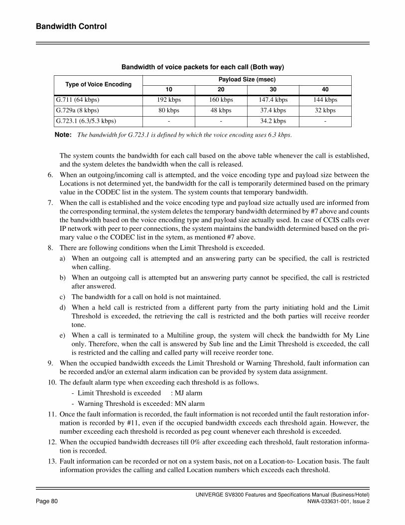
UNIVERGE SV8300 Features and Specifications Manual (Business/Hotel)Page 80 NWA-033631-001, Issue 2
Bandwidth Control
Note: The bandwidth for G.723.1 is defined by which the voice encoding uses 6.3 kbps.
The system counts the bandwidth for each call based on the above table whenever the call is established,and the system deletes the bandwidth when the call is released.
6. When an outgoing/incoming call is attempted, and the voice encoding type and payload size between theLocations is not determined yet, the bandwidth for the call is temporarily determined based on the primaryvalue in the CODEC list in the system. The system counts that temporary bandwidth.
7. When the call is established and the voice encoding type and payload size actually used are informed fromthe corresponding terminal, the system deletes the temporary bandwidth determined by #7 above and countsthe bandwidth based on the voice encoding type and payload size actually used. In case of CCIS calls overIP network with peer to peer connections, the system maintains the bandwidth determined based on the pri-mary value o the CODEC list in the sytem, as mentioned #7 above.
8. There are following conditions when the Limit Threshold is exceeded.
a) When an outgoing call is attempted and an answering party can be specified, the call is restrictedwhen calling.
b) When an outgoing call is attempted but an answering party cannot be specified, the call is restrictedafter answered.
c) The bandwidth for a call on hold is not maintained.
d) When a held call is restricted from a different party from the party initiating hold and the LimitThreshold is exceeded, the retrieving the call is restricted and the both parties will receive reordertone.
e) When a call is terminated to a Multiline group, the system will check the bandwidth for My Lineonly. Therefore, when the call is answered by Sub line and the Limit Threshold is exceeded, the callis restricted and the calling and called party will receive reorder tone.
9. When the occupied bandwidth exceeds the Limit Threshold or Warning Threshold, fault information canbe recorded and/or an external alarm indication can be provided by system data assignment.
10. The default alarm type when exceeding each threshold is as follows.
- Limit Threshold is exceeded : MJ alarm
- Warning Threshold is exceeded: MN alarm
11. Once the fault information is recorded, the fault information is not recorded until the fault restoration infor-mation is recorded by #11, even if the occupied bandwidth exceeds each threshold again. However, thenumber exceeding each threshold is recorded as peg count whenever each threshold is exceeded.
12. When the occupied bandwidth decreases till 0% after exceeding each threshold, fault restoration informa-tion is recorded.
13. Fault information can be recorded or not on a system basis, not on a Location-to- Location basis. The faultinformation provides the calling and called Location numbers which exceeds each threshold.
Bandwidth of voice packets for each call (Both way)
Type of Voice EncodingPayload Size (msec)
10 20 30 40
G.711 (64 kbps) 192 kbps 160 kbps 147.4 kbps 144 kbps
G.729a (8 kbps) 80 kbps 48 kbps 37.4 kbps 32 kbps
G.723.1 (6.3/5.3 kbps) - - 34.2 kbps -
UNIVERGE SV8300 Features and Specifications Manual (Business/Hotel)NWA-033631-001, Issue 2 Page 81
Bandwidth Control
14. Whether the call is restricted or not, when the Limit Threshold is exceeded, is assigned on a Location-to-Location basis by system programming.
15. When a call is restricted at originating the call, the calling party will hear reorder tone.
16. When a call is restricted at answering the call, both calling and called party will hear reorder tone.
17. When a call is restricted by this feature, no LCD indication is provided such as “RST”.
18. When an incoming CCIS call over IP network is restricted, the calling party will receive reorder tone.
19. When a CCIS call over IP network is restricted, the call can be routed to a legacy trunk route (TDM net-work).
UNIVERGE SV8300 Features and Specifications Manual (Business/Hotel)Page 82 NWA-033631-001, Issue 2
Boss/Secretary Calling
Boss/Secretary Calling
General Description
A secretary with a Multiline Terminal can use an appearance of the boss' extension to screen calls for that ex-tension, and announce and/or transfer calls to that extension. Additionally, the secretary can call the boss duringa busy condition and can send a Message Waiting Indication to the boss' station.
Station Application
Any type of station as boss extension and Multiline Terminal with appearance of boss extension at Secretaryposition.
Operating Procedure
For a Boss/Secretary transfer of an incoming call to the boss' Multiline Terminal
1. Secretary answers the incoming call by pressing boss' line key appearance and lifting the handset. Secretaryconverses with the calling party. Boss' line key appearance is steady green on secretary's station and steadyred at other appearances.
2. Secretary presses boss' line key appearance again. An incoming call is placed on Consultation Hold and re-ceives Music On Hold, if provided. Boss' line key appearance is steady green at secretary's station, steadygreen at boss' Multiline Terminal and steady red elsewhere.
3. At boss' Multiline Terminal a tone burst is heard followed by a voice call from the secretary (using the boss'primary extension) over the speaker. Secretary announces the call.
4. The secretary can now go on-hook. The boss' primary extension hears a chime tone and flashes on hold, red;the secretary's appearance of the Boss' extension flashes on hold, green, and all other line key appearancesof the boss' extension provide busy indication.
5. The boss lifts the handset or presses the primary extension line button and is connected to the calling party.
OR
The boss can lift the handset to answer the voice call and talk to the secretary privately using the handset.Boss' line key appearance is steady green at secretary and boss' Multiline Terminal, and is steady red else-where. The secretary then goes on-hook and the calling party is connected to the boss. Boss' line key ap-pearance is steady green at boss' terminal, and steady red elsewhere.
OR
The boss goes on-hook and the secretary presses the transfer key to return to the original call.
For a Boss/Secretary transfer of an incoming call to the boss’ Single Line Telephone
1. Secretary answers an incoming call by pressing boss' line key appearance and lifting the handset. Secretaryconverses with calling party. Boss' line key appearance is steady green on secretary's station and steady redelsewhere.
2. Secretary presses boss' line key appearance again. The incoming call is placed on Consultation Hold andreceives Music On Hold, if provided. Boss' line key appearance is steady green at secretary's station andsteady red at other appearances.
3. At boss' Single Line Telephone, internal ringing is heard.
UNIVERGE SV8300 Features and Specifications Manual (Business/Hotel)NWA-033631-001, Issue 2 Page 83
Boss/Secretary Calling
4. The secretary can now go on hook. The boss' Single Line Telephone continues to ring and all line key ap-pearances of the boss' extension provide incoming ring indication. The incoming ring rate reflects whetherthe calling party is internal or external.
5. The boss lifts the handset and is connected to the calling party.
OR
The boss can lift the handset while receiving internal ring to talk to the secretary. Boss' line key appearanceis steady green at the secretary's station and steady red elsewhere.
6. The secretary then goes on-hook, whereby the calling party is connected to the boss. Boss' line key appear-ance is steady red at all appearances.
OR
The boss goes on-hook and the secretary presses the Transfer key to return to the original call.
To set/cancel Message Waiting Indication to the boss from the secretary station
1. Lift handset and receive dial tone.
2. Dial the boss' extension number.
3. Press the Message Waiting set/cancel key (Boss' Message Wait Lamp is lit if set, goes off if canceled).
For a Boss/Secretary Override when the boss is busy on the primary extension of a Multiline Terminal and the secretary has a call on the primary extension of the secretary's Multiline Terminal
1. The secretary presses boss' line key appearance on the secretary's Multiline Terminal. The party that wasconnected to the secretary is placed on Hold and receives Music On Hold, if provided. Additionally, thesecretary hears special ringback tone and the boss hears one burst of tone through the handset to indicate acall is waiting. (If the secretary presses the Transfer key before the boss answers, the secretary is connectedto the calling party again. The secretary's Answer key is ineffective in this situation.)
2. The boss presses the Answer key. The party originally connected to the boss is now placed on ConsultationHold and the boss and secretary can converse.
3. The secretary goes on-hook. The boss is connected to the caller originally connected to the secretary. Thecaller originally connected to the boss is placed on Call Hold.
4. If the boss presses the Transfer key, the boss receives Special Dial Tone, allowing transfer of the new call.
5. When the boss goes on-hook, the original call recalls to the boss' station.
6. The boss goes off-hook and is connected to the original party.
For a Boss/Secretary override when the boss is busy on a Single Line Telephone, and the secretary has a call on the primary extension of the secretary's Multiline Terminal
1. The secretary presses the boss' line key appearance on the secretary's Multiline Terminal. The party that wasconnected to the secretary is placed on Hold and receives Music On Hold, if provided. Additionally, thesecretary hears special ringback tone and the boss hears one burst of tone through the handset to indicate acall is waiting.
2. The boss presses the FLASH key (or momentarily presses the hookswitch). At this time, the secretary andboss are connected and the other two parties are on Hold.
3. The secretary goes on hook. The boss is connected to the caller originally connected to the secretary. Theboss' original party remains on Call Hold.
4. The boss may now alternate between callers (Broker's Call) using the FLASH key.

UNIVERGE SV8300 Features and Specifications Manual (Business/Hotel)Page 84 NWA-033631-001, Issue 2
Boss/Secretary Calling
5. When finished conversing with either party, the boss goes on hook. The other party will automatically recallto the boss' station.
6. The boss goes off hook and is connected to the other party.
Service Conditions
1. During Boss/Secretary transfer operation, if the secretary hangs up before the boss answers to complete aring transfer and the boss still does not answer, the call will transfer again to the secretary's primary exten-sion after a predetermined time-out (default value is 24-28 seconds).
2. After the boss and secretary converse during a Boss/Secretary transfer operation, the secretary is automat-ically connected to the original caller again if the boss hangs up.
3. After the boss and secretary converse during a Boss/Secretary transfer operation, the secretary can use theTransfer or Answer key to alternate conversation between the original caller and the boss (Broker's Call)after the boss has answered using the handset.
4. After the boss and secretary converse during a Boss/Secretary transfer operation using the handsets, the sec-retary can press the Recall key to disconnect the boss and receive feature dial tone, allowing a transfer toanother station (the boss receives reorder tone). The secretary can also press either the Transfer or Answerkey to return to the original caller.
5. While a secretary is originating a voice call during the Boss/Secretary transfer or Boss/Secretary Overrideoperation, the secretary can press the Transfer key to return to the calling party and the voice call is aban-doned.
6. During a Boss/Secretary transfer operation, once the boss has answered and is conversing with the secre-tary, Privacy Release is not available and use of the Hold button will be disregarded at this time.
7. Setting or canceling of Message Waiting can be executed by the secretary, regardless of the boss' extensionstatus (busy or idle).
8. After the boss and secretary converse during a Boss/Secretary transfer or Boss/Secretary Override operationusing the handsets, the secretary can use the Answer key to alternate conversations between the originalcalling party and the boss (Brokers Call). The secretary can also press the Transfer key, sending the secre-tary back to the original calling party and the boss back to the party on Consultation Hold.
9. During a Boss/Secretary Override operation, the boss can use the Answer key to answer the Override Call.The boss can then use the Answer key to alternate between the secretary and the party on ConsultationHold.
10. During a Boss/Secretary Override operation, once the boss has answered and the secretary has gone on-hook, the boss can use the Answer key to alternate between the two parties. The boss can also use the Trans-fer key to receive Special Dial Tone.
UNIVERGE SV8300 Features and Specifications Manual (Business/Hotel)NWA-033631-001, Issue 2 Page 85
Broker's Call
Broker's Call
General Description
This feature allows a Multiline Terminal or Single Line Telephone user to alternate between two parties, talkingto one party while the other party remains on Hold on the same line. The Multiline Terminal user uses the Trans-fer or Answer key to alternate between the two parties. The Single Line Telephone user uses the Hold featureto alternate between the two parties.
Station Application
All stations.
Operating Procedure
To activate Broker's Call from a Multiline Terminal with a call in progress
1. Press the Transfer key and receive feature dial tone. The first party is placed on hold.
2. Dial the new number and wait for the second party to answer.
3. Press the Transfer or Answer key and return to the first party. The second party is placed on hold.
4. Repeat as often as needed.
To activate a Broker's Call from a Single Line Telephone with a call in progress
1. Press the FLASH key (or momentarily press hookswitch) and receive feature dial tone. The first party isplaced on Consultation Hold.
2. Dial the Call Hold feature access code and receive extension dial tone.
3. Dial the new number and the second party answers.
4. Press the FLASH key (or momentarily press the hookswitch). The second party is placed on ConsultationHold.
5. Dial the Call Hold feature access code and the second party is placed on Call Hold. The first party is con-nected again.
6. Repeat the last two steps, as necessary.
Service Conditions
1. A three-way call may be established any time during a Broker's Call by pressing the Conf key on a MultilineTerminal.
2. Once a Single Line Telephone has set up a Broker's Call, a Conference cannot be established.
3. The party on hold during a Broker's Call will receive Music on Hold, if provided.
4. If the Recall key is pressed with a Broker's Call in progress, the currently connected party is dropped. Theparty on Consultation Hold remains on Consultation Hold and new feature dial tone is provided. Restoringthe handset allows the Consultation Hold call to recall.
5. A Broker's call can also be initiated after receiving a Camp-On call. See Camp-on.

UNIVERGE SV8300 Features and Specifications Manual (Business/Hotel)Page 86 NWA-033631-001, Issue 2
Broker's Call
6. When a Multiline Terminal has a Broker's Call in progress, the Answer key alternates between the calls andwill not answer additional incoming calls.

UNIVERGE SV8300 Features and Specifications Manual (Business/Hotel)NWA-033631-001, Issue 2 Page 87
Call Back
Call Back
General Description
This feature allows a calling party to set an automatic Call Back when a busy or no answer condition is encoun-tered. When the busy station becomes idle, the station that set the Call Back will be called. In case of Call Backno answer, the Call Back to the setting station is initiated immediately after the called station goes on hook aftermaking a call or accessing a feature.
Station Application
All stations.
Operating Procedure
To set Call Back from a Dial Pulse Single Line Telephone
1. Dial the desired station number and receive busy tone or ringback tone.
2. Dial “2” and receive service set tone (if single digit feature access codes are enabled),
OR
Press the FLASH key (or momentarily press the hookswitch) and receive feature dial tone. Dial the CallBack feature access code if busy tone, dial 2 if ringback tone (if single feature access codes are enabled),and receive service set tone.
3. Restore the handset.
4. When the busy station becomes idle, the station that set the Call Back will ring. The same will happen if thestation that did not answer first initiates or answers a call or accesses a feature and then becomes idle.
5. Upon the originator answering, the originally called station will ring.
To set Call Back from a DTMF Telephone
1. Dial the desired station number and receive busy tone or ringback tone.
2. Dial “2” and receive service set tone (if single digit access feature access codes are enabled) for busy toneonly.
OR
Press the FLASH key (or momentarily press the hookswitch) and receive feature dial tone. Dial the CallBack feature access code if busy tone, dial 2 if ringback tone and receive service set tone.
3. Restore the handset.
4. When the busy station becomes idle, the station that set the Call Back will ring. The same will happen if thestation that did not answer first initiates or answers a call or accesses a feature and then becomes idle.
5. Upon answering, the originally called station will ring.
Note: Multiple Call Backs can be set by repeating the procedure above.
To set Call Back from a Multiline Terminal
1. Dial desired station number and receive busy tone or ringback tone.
UNIVERGE SV8300 Features and Specifications Manual (Business/Hotel)Page 88 NWA-033631-001, Issue 2
Call Back
2. Press the CALL BACK key or dial “2” and receive service set tone.
3. Restore handset.
4. When the busy station becomes idle, the station that set the Call Back will ring. The same will happen if thestation that did not answer first initiates or answers a call or accesses a feature and then becomes idle.
Note: Multiple Call Backs can be set by repeating the procedure above.
To cancel Call Back from a Single Line Telephone
1. Lift the handset and receive dial tone.
2. Dial the Call Back cancellation code and receive service set tone.
To cancel Call Back from a Multiline Terminal
1. Lift the handset or press the Speaker key and receive dial tone.
2. Press the CALL BACK key and receive service set tone.
Service Conditions
1. If a Call Back is not answered by the originator within 30 seconds, the Call Back is automatically cancelled.
2. A Call Back to a station in Line Lockout is denied.
3. Dial pulse Single Line Telephones can omit pressing the FLASH key (or momentarily pressing the hook-switch) to set call back while receiving ringback tone.
4. If the station presses the FLASH key while receiving feature dial tone before setting the Call Back, the sta-tion then receives ringback tone again.
5. When the called party is an Attendant Console, Call Back cannot be set.
6. When the setting station is called back, Station Hunting and Call Pickup will not apply.
7. When the call is placed in UCD queue, Call Back cannot be set.
8. A maximum of 128 stations can access this feature simultaneously.
9. This feature can be allowed or denied in Class of Service assignment.
10. Call Back cannot be set from a station, which has been set Call Forwarding - All Calls.

UNIVERGE SV8300 Features and Specifications Manual (Business/Hotel)NWA-033631-001, Issue 2 Page 89
Call Forwarding
Call Forwarding
General Description
Call Forwarding allows calls directed to a station to be routed to another station, an Attendant, an outside num-ber or voice mail equipment. The types of Call Forwarding provided are:
• Call Forwarding - All Calls*
• Call Forwarding - Busy Line*
• Call Forwarding - No Answer*
• Call Forwarding - Destination
• Multiple Call Forwarding - All Calls
• Multiple Call Forwarding - Busy Line
• Multiple Call Forwarding - No Answer
• Split Call Forwarding - All Calls*
• Split Call Forwarding - Busy Line*
• Split Call Forwarding - No Answer*
Additional Call Forwarding features include:
• Attendant Call Forwarding Setup and Cancel
• Call Forwarding - Logout
• Call Forwarding - Override
• Group Diversion
These features can be set/canceled from each station. The features marked by “*” can be set/canceled from aPCPro/CAT.
When the features marked by “*” are set/canceled from a PCPro/CAT, the LED indication of the Multiline Ter-minal changes as it would if the features were set/canceled from the Multiline Terminal.
A PCPro/CAT can overwrite or cancel these features marked by “*” that are set by each station, and vice versa.
A maximum of 496 Call Forwarding to outside number can be set simultaneously per system.

UNIVERGE SV8300 Features and Specifications Manual (Business/Hotel)Page 90 NWA-033631-001, Issue 2
October, 2008
Call ForwardingAttendant Call Forwarding Setup and Cancel
Attendant Call Forwarding Setup and Cancel
General Description
All of the various types of Call Forwarding can be set up or cancelled from the Attendant Console.
Station Application
All stations.
Operating Procedure
To set Call Forwarding - All Calls from the Attendant Console
1. Press an idle LOOP key.
2. Dial the Call Forwarding - All Calls feature access code and receive feature dial tone.
3. Dial the originating station number.
4. Dial the desired target station number and receive service set tone.
To cancel Call Forwarding - All Calls from the Attendant Console
1. Press an idle LOOP key.
2. Dial the Call Forwarding - All Calls feature cancellation code and receive feature dial tone.
3. Dial the originating station number and receive service set tone.
To set Call Forwarding - Busy Line from the Attendant Console
1. Press an idle LOOP key.
2. Dial the Call Forwarding - Busy Line feature access code and receive feature dial tone.
3. Dial the originating station number.
4. Dial the desired target station number and receive service set tone.
To cancel Call Forwarding - Busy Line from the Attendant Console
1. Press an idle LOOP key.
2. Dial the Call Forwarding - Busy Line cancellation code and receive feature dial tone.
3. Dial the originating station number and receive service set tone.
To set Call Forwarding - No Answer from the Attendant Console
1. Press an idle LOOP key.
2. Dial the Call Forwarding - No Answer feature access code and receive feature dial tone.
3. Dial the originating station number.
4. Dial the desired target station number and receive service set tone.
To cancel Call Forwarding - No Answer from the Attendant Console
1. Press an idle LOOP key.
UNIVERGE SV8300 Features and Specifications Manual (Business/Hotel)NWA-033631-001, Issue 2 Page 91
October, 2008
Call ForwardingAttendant Call Forwarding Setup and Cancel
2. Dial the Call Forwarding - No Answer cancellation code and receive feature dial tone.
3. Dial the originating station number and receive service set tone.
Service Conditions
The Attendant can cancel any type of Call Forwarding set by an internal station.

UNIVERGE SV8300 Features and Specifications Manual (Business/Hotel)Page 92 NWA-033631-001, Issue 2
Call ForwardingCall Forwarding - All Calls
Call Forwarding - All Calls
General Description
This feature allows all calls directed to a particular extension to be rerouted to an alternate destination, regard-less of the busy or idle status of the extension. Call Forwarding - All Calls can be set by an Attendant Console,the individual station user, a Multiline Terminal with a secondary appearance of the station's extension, or fromanother station (that can program itself to be the destination of the rerouting).
Station Application
All stations.
Operating Procedure
From a Multiline Terminal with LCD
To set Call Forwarding - All Calls
1. Lift the handset or press the Speaker key and receive dial tone.
2. Press the Call Forwarding - All Calls feature access key and receive feature dial tone.
3. Dial the desired target station number and receive service set tone. The associated LED lights and the LCDdisplays:
SET XXXX or SET OPR(Target Station) (Operator)
4. Replace the handset or press the Speaker key.
To set Call Forwarding - All Calls - Outside
1. Lift the handset or press the Speaker key and receive dial tone.
2. Press the Call Forwarding - All Calls feature access key and receive feature dial tone.
3. Dial the trunk access code and the desired telephone number.
4. Wait till service set tone is received, unless programming system data.
5. Replace the handset or press the Speaker key.
To monitor Call Forwarding - All Calls
1. Lift the handset or press the Speaker key and receive dial tone or special dial tone (when lifting the hand-set).
2. Press the Call Forwarding - All Calls feature access key. The LCD displays:
CF CALL XXXX(Target Station)
3. Replace the handset or press the Speaker key.
To cancel Call Forwarding - All Calls
1. Lift the handset or press the Speaker key and receive dial tone.

UNIVERGE SV8300 Features and Specifications Manual (Business/Hotel)NWA-033631-001, Issue 2 Page 93
Call ForwardingCall Forwarding - All Calls
2. Press the Call Forwarding All Calls feature access key and receive special dial tone. The LCD displays:
CF CALL XXXX(Target Station)
3. Press the * key and receive service set tone. The LED of the associated feature key will go out. The LCDdisplays CANCEL.
4. Replace the handset or press the Speaker key.
From a Single Line Telephone
To set Call Forwarding - All Calls
1. Lift the handset and receive dial tone.
2. Dial the Call Forwarding - All Calls feature access code and receive feature dial tone.
3. Dial the desired target station number and receive service set tone.
To set Call Forwarding - All Calls - Outside
1. Lift the handset and receive dial tone.
2. Dial the Call Forwarding - All Calls feature access code and receive feature dial tone.
3. Dial the trunk access code and desired telephone number.
4. Wait until service set tone is received, unless programming system data.
5. Replace the handset.
To monitor Call Forwarding - All Calls
1. Lift the handset.
2. When Call Forwarding - All Calls has been set, special dial tone is heard.
3. Replace the handset.
To cancel Call Forwarding - All Calls
1. Lift the handset and receive dial tone.
2. Dial the Call Forwarding - All Calls cancellation code and receive service set tone.
Service Conditions
1. There is no limit to the number of stations that can set Call Forwarding - All Calls at one time.
2. Extensions can be allowed or disallowed this feature by Class of Service in system programming. A sepa-rate Class of Service Assignment controls access to Call Forwarding - All Calls to outside numbers.
3. When Call Forwarding - All Calls is rerouted to another destination, one burst of ringing is sent to the for-warded station to indicate that it is call forwarded (Single Line Telephone only).
4. When a call is forwarded to a Multiline Terminal with LCD, the display shows the number of the stationthat was called first as well as the calling station's number.
5. Call Forwarding - All Calls assignments are retained in system memory when the system is re-initialized orwhen there is a power failure.
6. A maximum of 26 digits (without access code) can be stored for Call Forwarding - All Calls to an outsidenumber.

UNIVERGE SV8300 Features and Specifications Manual (Business/Hotel)Page 94 NWA-033631-001, Issue 2
Call ForwardingCall Forwarding - All Calls
7. Call Forwarding - All Calls to an outside number can be routed by the Least Cost Routing feature and re-stricted by the Code Restriction feature.
8. More than one Call Forward can occur in the progress of a call. See Multiple Call Forwarding - All Calls,Multiple Call Forwarding - Busy Line, and Multiple Call Forwarding - No Answer.
9. Direct Inward Dial (DID) lines, DIT calls, Tie lines, ring transfer and internal incoming calls will followthe Call Forward setting.
10. Only the destination station can call the station that is Call Forwarded.
11. If the Call Forward is rerouted to a hunt group and all members of the hunt group are busy, the forwardedcaller will receive busy tone.
12. If the Call Forward is rerouted to the pilot number of an Automatic/Uniform Call Distribution (UCD) groupand that pilot station has set Call Forward, the call will be forwarded.
13. When Call Forwarding - All Calls - Outside is set, the system can be programmed to allow or deny the set-ting of the Call Forward with only a trunk access code. This can be set on a system-wide basis.
14. In the SMDR call record, the station that set Call Forwarding - All Calls - Outside will appear as the origi-nator of the call.
15. SMDR only records if the Tandem Connection receives answer supervision.
16. The setting station's trunk restriction class is used to allow or deny the tandem connection on a Call For-warding - All Calls - Outside.
17. Checking of the setting station's trunk restriction class can be allowed or denied on a system-wide basis.
18. A Direct Inward System Access (DISA) call to a station set for Call Forwarding - All Calls - Outside willbe allowed or denied based on the forwarded station's trunk restriction class.
19. An internal station call to a station set for Call Forwarding - All Calls - Outside will follow the restrictionclass of the station set Call Forwarding.When Call Forwarding to outside is executed, an object of the billing is as follows.
20. When the station user that has set Call Forwarding lifts the handset, the station can receive special dial toneby system programming.
21. A maximum of 496 Call Forwarding setting to outside number is allowed per system, including Call For-warding - All Calls, Busy Line, No Answer.
22. When Call Forwarding - All Calls - Outside is set, the trunk route is selectable by tenant of the station setCall Forwarding or tenant of the originating station/trunk.
23. When an incoming trunk call is forwarded by Call Forwarding - Outside, CLI of the forwarding station canbe presented to ISDN by system data programming.
Station Set Call Forwarding Billing Object
Single Line Telephone, Multiline Terminal
Station set Call Forwarding
Virtual station Originating station/trunk

UNIVERGE SV8300 Features and Specifications Manual (Business/Hotel)NWA-033631-001, Issue 2 Page 95
Call ForwardingCall Forwarding - Busy Line
Call Forwarding - Busy Line
General Description
This feature permits a call to a busy extension to be routed to a designated station, Attendant Console, or voicemail equipment. Call Forwarding - Busy Line can be set or cancelled by an Attendant Console, the individualstation user, or a Multiline Terminal with a secondary appearance of the station's extension.
Station Application
All stations.
Operating Procedure
From a Multiline Terminal with LCD
To set Call Forwarding - Busy Line
1. Lift the handset or press the Speaker key and receive dial tone.
2. Press the Call Forwarding - Busy Line feature access key and receive feature dial tone.
3. Dial the desired target station number and receive service set tone. The LCD displays:
SET XXXX or SET OPR(Target Station) (Operator)
4. The LED of the associated feature button lights.
5. Restore the handset or press the Speaker key.
To monitor Call Forwarding - Busy Line
1. Lift the handset or press the Speaker key and receive dial tone.
2. Press the Call Forwarding - Busy Line feature access key. The LCD displays:
CF BUSY XXXX (Target Station)
3. Replace the handset or press the Speaker key.
To set Call Forwarding - Busy Line - Outside
1. Lift the handset or press the Speaker key and receive dial tone.
2. Press the Call Forwarding - Busy Line feature access key and receive feature dial tone.
3. Dial the trunk access code and desired telephone number.
4. Wait till service set tone is received (unless programming system data).
5. Replace the handset or press the Speaker key.
To cancel Call Forwarding - Busy Line
1. Lift the handset or press the Speaker key and receive dial tone.
2. Press the Call Forwarding - Busy Line feature access key and receive special dial tone. Press the * key andreceive service set tone. The LCD displays CANCEL and the associated LED goes out.
3. Restore the handset or press the Speaker key.
UNIVERGE SV8300 Features and Specifications Manual (Business/Hotel)Page 96 NWA-033631-001, Issue 2
Call ForwardingCall Forwarding - Busy Line
From a Single Line Telephone
To set Call Forwarding - Busy Line
1. Lift the handset and receive dial tone.
2. Dial the Call Forwarding - Busy Line feature access code and receive feature dial tone.
3. Dial the desired target station number and receive service set tone.
To set Call Forwarding - Busy Line - Outside
1. Lift the handset and receive dial tone.
2. Dial the Call Forwarding - Busy Line feature access code and receive feature dial tone.
3. Dial the trunk access code and the desired telephone number.
4. Wait until the service set tone is received.
5. Replace the handset.
To cancel Call Forwarding - Busy Line
1. Lift the handset and receive dial tone.
2. Dial the Call Forwarding - Busy Line cancellation code and receive service set tone.
Service Conditions
1. There is no limit to the number of stations that can set Call Forwarding - Busy Line at one time.
2. Extensions can be allowed or denied this feature by Class of Service in system programming.
3. Call Forwarding - Busy Line can be provided on a system or an individual basis.
4. Call Forwarding - Busy Line on a system basis allows the following types of incoming calls to be forwardedto another device (Attendant Console, another station, or voice mail equipment) when they encounter a busycondition:
• Direct Inward Dial (DID)
• Direct Inward Termination (DIT)
• Tie line
• Transfer
• internal
5. Individually set Call Forwarding - Busy Line settings take precedence over system basis Call Forwarding -Busy Line settings.
6. If the Call Forwarding - Busy Line is rerouted to a hunt group and all members of the hunt group are busy,the forwarded caller will receive busy tone.
7. When a call is directed to the pilot number of an ACD/UCD group and that pilot station has set Call For-warding - Busy Line, the call will be forwarded if all stations within the ACD/UCD group are busy.
8. When a calling station or Attendant Console receives busy tone after being forwarded because of Call For-warding - Busy Line, the caller can activate any of the following:
• Executive Override
• Camp On
• Attendant Override
• Call Back

UNIVERGE SV8300 Features and Specifications Manual (Business/Hotel)NWA-033631-001, Issue 2 Page 97
Call ForwardingCall Forwarding - Busy Line
• Message Reminder
9. When a call is forwarded to a Multiline Terminal with LCD, the display shows the original called station'snumber as well as the calling station's number.
10. Call Forwarding - No Answer can be set simultaneously with this feature to result in Call Forwarding - BusyLine/No Answer. Call Forwarding - Busy Line and Call Forwarding - No Answer can be set to the same ordifferent extensions.
11. When Call Forwarding - Busy Line - Outside is set, the system can be programmed to allow or deny thesetting of the Call Forward with only a trunk access code. This can be set on a system-wide basis.
12. In the Station Message Detail Recording (SMDR) call record, the station that set Call Forwarding - BusyLine - Outside will appear as the originator of the call.
13. SMDR only records if the Tandem Connection receives answer supervision.
14. The setting station's trunk restriction class is used to allow or deny the tandem connection on a Call For-warding - Busy Line - Outside.
15. Checking of the setting station's trunk restriction class can be allowed or denied on a system-wide basis.
16. A Direct Inward System Access (DISA) call to a station set for Call Forwarding - Busy Line - Outside willbe allowed or denied based on the forwarded station's trunk restriction class.
17. An internal station call to a station set for Call Forwarding - Busy Line - Outside will follow the restrictionclass of the station set Call Forwarding.When Call Forwarding to outside is executed, an object of the billing is as follows.
18. A maximum of 496 Call Forwarding setting to outside number is allowed per system, including Call For-warding - All Calls, Busy Line, No Answer.
19. When Call Forwarding - Busy Line - Outside is set, the trunk route is selectable by tenant of station set CallForwarding or tenant of the originating station/trunk.
20. When an incoming trunk call is forwarded by Call Forwarding - Outside, CLI of the forwarding station canbe presented to ISDN by system data programming.
Station Set Call Forwarding Billing Object
Single Line Telephone, Multiline Terminal
Station set Call Forwarding
Virtual station Originating station/trunk
UNIVERGE SV8300 Features and Specifications Manual (Business/Hotel)Page 98 NWA-033631-001, Issue 2
Call ForwardingCall Forwarding - No Answer
Call Forwarding - No Answer
General Description
When a call is placed to a station that does not answer, this feature forwards the call to another station, an At-tendant Console or voice mail equipment. Call Forwarding - No Answer can be set by the individual stationuser, an Attendant Console, or by a Multiline Terminal with a secondary appearance of the station's extension.
Station Application
All stations.
Operating Procedure
From a Multiline Terminal with LCD
To set Call Forwarding - No Answer
1. Lift the handset or press the Speaker key and receive dial tone.
2. Press the Call Forwarding - No Answer feature access key and receive feature dial tone.
3. Dial the desired target station number and receive service set tone. The LCD displays:
SET XXXX (Target Station)
To set Call Forwarding - No Answer - Outside
1. Lift the handset or press the Speaker key and receive dial tone.
2. Press the Call Forwarding - No Answer feature access key and receive feature dial tone.
3. Dial the trunk access code and the desired telephone number.
4. Wait until service set tone is received.
5. Replace the handset or press the Speaker key.
To cancel Call Forwarding - No Answer
1. Lift handset or press Speaker key and receive dial tone.
2. Press the Call Forwarding - No Answer feature access key and receive special dial tone. Press the * key, theassociated LED goes out and service set tone is received. The LCD displays CANCEL.
From a Single Line Telephone
To set Call Forwarding - No Answer
1. Lift handset and receive dial tone.
2. Dial Call Forwarding - No Answer feature access code and receive feature dial tone.
3. Dial the desired target station number and receive service set tone.
To set Call Forwarding - No Answer - Outside
1. Lift the handset and receive Dial Tone.
2. Dial Call Forwarding - No Answer feature access code and receive feature dial tone.
3. Dial the trunk access code and the desired telephone number.

UNIVERGE SV8300 Features and Specifications Manual (Business/Hotel)NWA-033631-001, Issue 2 Page 99
Call ForwardingCall Forwarding - No Answer
4. Wait until service set tone is received.
5. Replace the handset.
To cancel Call Forwarding - No Answer
1. Lift handset and receive dial tone.
2. Dial specific Call Forwarding - No Answer cancellation code and receive service set tone.
Service Conditions
1. An unlimited number of stations can set Call Forwarding - No Answer at one time.
2. Stations are allowed/disallowed this feature by Class Of Service in system programming.
3. Call Forwarding - No Answer can be provided on a system and an individual basis.
4. Call Forwarding on a system basis allows Direct Inward Dial (DID) calls or Tie Line calls that encounter ano-answer condition to be forwarded to a predetermined location (Attendant Console, another station, orvoice mail equipment).
5. Individual Call Forwarding - No Answer settings take precedence over system Call Forwarding - No An-swer settings.
6. Call Forwarding - No Answer timing, flexible in system programming, is as follows:
• For direct incoming calls (DID, DIT, Tie) – 4 to 120 seconds (Default: 32-36 seconds).
• For internal calls and transferred incoming calls – 4 to 120 seconds (Default: 32-36 seconds).
This timing can be assigned on a system basis or a station basis.
7. More than one call forward can occur in the progress of a call. See Multiple Call Forwarding - All Calls,Multiple Call Forwarding - Busy Line and Multiple Call Forwarding - No Answer.
8. Call Forwarding - Busy Line can be set simultaneously with this feature to result in Call Forwarding - BusyLine/No Answer. Call Forwarding - Busy Line and Call Forwarding - No Answer can be set to the same ordifferent extensions.
9. When Call Forwarding - No Answer - Outside is set, the system can be programmed to allow or deny thesetting of the Call Forward with only a trunk access code. This can be set on a system-wide basis.
10. In the SMDR call record, the station that set Call Forwarding - No Answer - Outside will appear as the orig-inator of the call.
11. SMDR only records if the Tandem Connection receives answer supervision.
12. The setting station's trunk restriction class is used to allow or deny the tandem connection on a Call For-warding - No Answer - Outside.
13. Checking of the setting station's trunk restriction class can be allowed or denied on a system-wide basis.
14. A Direct Inward System Access (DISA) call to a station set for Call Forwarding - No Answer - Outside willbe allowed or denied based on the forwarded station's trunk restriction class.
15. An internal station call to a station set for Call Forwarding - No Answer - Outside will follow the restrictionclass of the station set Call Forwarding.When Call Forwarding to outside is executed, an object of the billing is as follows.
Station Set Call Forwarding Billing Object
Single Line Telephone, Multiline Terminal
Station set Call Forwarding

UNIVERGE SV8300 Features and Specifications Manual (Business/Hotel)Page 100 NWA-033631-001, Issue 2
Call ForwardingCall Forwarding - No Answer
16. A maximum of 496 Call Forwarding setting to outside number is allowed per system, including Call For-warding - All Calls, Busy Line, No Answer.
17. When Call Forwarding - No Answer - Outside is set, the trunk route is selectable by tenant of station setCall Forwarding or tenant of the originating station/trunk.
18. When an incoming trunk call is forwarded by Call Forwarding - Outside, CLI of the forwarding station canbe presented to ISDN by system data programming.
Virtual station Originating station/trunk
Station Set Call Forwarding Billing Object

UNIVERGE SV8300 Features and Specifications Manual (Business/Hotel)NWA-033631-001, Issue 2 Page 101
Call ForwardingCall Forwarding - Destination
Call Forwarding - Destination
General Description
This feature allows a station (A) user to set Call Forwarding - All Calls from another station (B) within the sys-tem, to the user's station (A).
Station Application
All stations.
Operating Procedure
From a Multiline Terminal with LCD
To set Call Forwarding - Destination from destination station
1. Lift the handset or press the Speaker key and receive dial tone.
2. Press the Call Forwarding - Destination set key or dial the Call Forwarding - Destination feature access codeand receive feature dial tone.
3. Dial the station number to be forwarded and receive service set tone. The LCD displays:
SET XXXX(Forwarded Station)
4. Replace the handset or press Speaker key.
To cancel Call Forwarding - Destination from destination station
1. Lift the handset or press the Speaker key and receive dial tone.
2. Press the Call Forwarding - Destination Cancel key or dial the Call Forwarding - Destination Cancellationcode and receive feature dial tone.
3. Dial the user's station number (forwarded station) and receive set tone.
4. Replace the handset or press the Speaker key.
From a Single Line Telephone
To set Call Forwarding - Destination from destination station
1. Lift the handset and receive dial tone.
2. Dial the specific Call Forwarding - Destination feature access code and receive Dial Tone.
3. Dial the station number to be forwarded and receive service set tone.
To cancel Call Forwarding - Destination from destination station
1. Lift the handset and receive dial tone.
2. Dial the Call Forwarding - Destination cancellation code and receive feature dial tone.
3. Dial the user's station number (forwarded station) and receive service set tone.

UNIVERGE SV8300 Features and Specifications Manual (Business/Hotel)Page 102 NWA-033631-001, Issue 2
Call ForwardingCall Forwarding - Destination
To cancel Call Forwarding - Destination from Call Forwarded station
1. Lift the handset and receive dial tone.
2. Dial the Call Forwarding - All Calls cancellation code and receive service set tone.
Service Conditions
1. There is no limit to the number of stations that can set Call Forwarding - Destination.
2. Stations can be allowed or denied this feature by Class Of Service in system programming.
3. There is no limit to the number of Call Forwarding - Destinations that can be set to forward to a station si-multaneously.

UNIVERGE SV8300 Features and Specifications Manual (Business/Hotel)NWA-033631-001, Issue 2 Page 103
Call ForwardingMultiple Call Forwarding - All Calls
Multiple Call Forwarding - All Calls
General Description
When a forwarded call is rerouted to a station that has also set a Call Forward, the call can be forwarded to an-other station. A call can be forwarded up to a maximum of five times, as specified in system programming.
Station Application
All stations.
Operating Procedure
The same operating procedures for Call Forwarding - All Calls apply.
Service Conditions
1. Multiple Call Forwarding - All Calls can forward a maximum of five times when the called station sets CallForwarding - All Calls to a station that has set Call Forwarding - All Calls or Call Forwarding - Busy Line.
2. Multiple Call Forwarding - All Calls cannot be performed for data calls.
3. If a calling station has been set to Call Forwarding - All Calls five times and encounters a sixth Call For-warding - All Calls, the calling station is not forwarded. Instead, it receives busy tone if the destination sta-tion is busy, or ringback tone if the destination station is idle.
4. If the destination of Call Forwarding - All Calls is set for Call Forwarding - Busy Line and is busy, forward-ing occurs.
5. When combining Call Forwarding - All Calls and Call Forwarding - Busy Line, and the fifth destinationstation is busy, the calling party will hear busy tone.
6. If a destination in a Multiple Call Forwarding - All Calls situation is busy, and has not set Call Forwarding- Busy Line or All Calls, the calling party will receive busy tone.
7. If a destination station is busy, the calling station can activate Call Back, Camp On, Message Reminder, orExecutive Override to that destination station.
8. When Multiple Call Forwarding - All Calls occurs, the display of the calling party's Multiline Terminal withLCD will show the station number to which the call was forwarded. The display of the answering MultilineTerminal with LCD will show the calling party (station or trunk) and the called number.
9. If the destination station in a combined Multiple Call Forwarding - All Calls and Call Forwarding - BusyLine situation is forwarded through Call Forwarding - No Answer, then Multiple Call Forwarding - No An-swer will be put into effect. If the destination station of Call Forwarding - No Answer is set to Call Forward-ing - Busy Line, then Call Forwarding - All Calls forwarding will be restricted.
10. If two stations have set Call Forwarding - All Calls to each other, an incoming call to either of these stationswill not be forwarded. Therefore, an infinite loop cannot occur.
11. If the incoming call returns to a station that has already taken part in a Multiple Call Forwarding (Busy orAll Calls) of that call, Call Forwarding - All Calls service from that station is not be performed again.
12. If an incoming call encounters Multiple Call Forwarding - All Calls and the final destination of the call for-ward is the Attendant Console, the incoming call will appear on the ATND key.

UNIVERGE SV8300 Features and Specifications Manual (Business/Hotel)Page 104 NWA-033631-001, Issue 2
Call ForwardingMultiple Call Forwarding - All Calls
13. If a station has set Call Forwarding - All Calls to another station in a different tenant and that station is setto Call Forwarding - Busy Line or All Calls to the Attendant Console, the calling station will be connectedto the first station's Attendant Console.
14. A Direct In Termination call to a station that has set Call Forwarding - All Calls will be forwarded. The callcan be forwarded to another station or to an Attendant Console.
15. If the destination station of Multiple Call Forwarding - All Calls is in a hunt group and is set by Call For-warding - Busy Line to a station in another hunt group, system data can assign further hunting. The callingparty can hunt to the called party's hunt group or to the terminating party's hunt group when the forwardedto stations are busy.
16. If the destination of Multiple Call Forwarding - All Calls is the pilot of an Automatic/Uniform Call Distri-bution (ACD/UCD) group, ACD/UCD is executed.
17. If a member of an ACD/UCD group is a member of a Multiple Call Forwarding - All Calls sequence, thatstation is skipped in ACD/UCD hunting.

UNIVERGE SV8300 Features and Specifications Manual (Business/Hotel)NWA-033631-001, Issue 2 Page 105
Call ForwardingMultiple Call Forwarding - Busy Line
Multiple Call Forwarding - Busy Line
General Description
This feature permits a call to a busy station to be forwarded multiple times to a designated idle station.
Station Application
All stations.
Operating Procedure
The same operating procedures for Call Forwarding - All Calls apply.
Service Conditions
1. Multiple Call Forwarding - Busy Line cannot be performed for data calls.
2. Multiple Call Forwarding - Busy Line can route a call up to five times when the called station sets Call For-warding - Busy Line to a station that is busy that has set Call Forwarding - Busy Line and so on.
3. If the calling station is set as the forwarded destination of its own call in a multiple call forwarding scheme,Call Forwarding - Busy Line at that point will not take place.
4. If the incoming call returns to one of the stations that has taken part in the process of multiple call forward-ing, the Call Forwarding - Busy Line from that station will not be performed.
5. If all the stations are busy in a multiple call forwarding sequence, a calling internal station may then activateCall Back, Message Reminder, Camp On, or Executive Override to the called station.
6. If the station is a Direct In Termination call, Call Forwarding - Busy Line is not activated. The calling partymay be forwarded to the Attendant Console, to Trunk Answer any Station, put in Automatic Camp-On, orcan receive ringback until the station becomes idle.
7. If the called station is set as the forwarded destination in a multiple call forwarding scheme, Call Forwarding- Busy Line at that point will not take place.
8. If the called station is set to Call Forwarding - Busy Line to another station in a different tenant and thatstation is set to Call Forwarding - Busy Line to the Attendant Console, the calling station will be connectedto the calling station's Attendant Console.
9. For Multiple Call Forwarding - Busy Line, the display of a Multiline Terminal with LCD will show thecalled station number and the final forwarded station number for the calling party. For the final forwarded-to station, the display of the Multiline Terminal with LCD will show the called number and the calling party(station or trunk).
UNIVERGE SV8300 Features and Specifications Manual (Business/Hotel)Page 106 NWA-033631-001, Issue 2
Call ForwardingMultiple Call Forwarding - No Answer
Multiple Call Forwarding - No Answer
General Description
This feature permits a call to an unanswered station, the ability to be forwarded multiple times to a designatedstation that does not have Call Forwarding - No Answer set or to the Attendant Console.
Station Application
All stations.
Operating Procedure
The same operating procedures for Call Forwarding - All Calls apply.
Service Conditions
1. Multiple Call Forwarding - No Answer can only be performed for non-data calls.
2. Multiple Call Forwarding - No Answer can be forwarded as many times as desired. The call will stop for-warding when it terminates to the Attendant Console or to a station not assigned with Call Forwarding - NoAnswer.
3. When a station encounters a Call Forwarding - No Answer condition and the station it is forwarded to isbusy, the system will check the status of the busy station at intervals assigned in system programming.
4. Multiple Call Forwarding - No Answer service can be used by the following incoming calls:
• Intra-office• Direct Inward Dialing• Direct In Termination• Night Service• Hot Line
5. If a station transfers a call to another station that set Call Forwarding - No Answer and releases from theconnection, recalls will override Call Forwarding - No Answer if the call is unanswered after a pre-deter-mined time.
6. Multiple Call Forwarding - No Answer will not be activated if the calling party encounters a busy stationthat has activated Call Forwarding - Busy Line.
7. If a station sets Call Forwarding - No Answer to another station in a different tenant and that station is setto Call Forwarding - No Answer to the Attendant, the calling station will be connected to the calling station'sAttendant Console.
8. For Multiple Call Forwarding - No Answer, the display of a Multiline Terminal with LCD will show thefinal forwarded-to station number for the calling party. If the final forwarded-to station is a multiline termi-nal with LCD, the forwarded-from station number and the calling party number (station on trunk) will bedisplayed.

UNIVERGE SV8300 Features and Specifications Manual (Business/Hotel)NWA-033631-001, Issue 2 Page 107
Call ForwardingSplit Call Forwarding - All Calls
Split Call Forwarding - All Calls
General Description
This feature allows all internal and external calls to a busy extension to be rerouted to different destinations in-dividually, regardless of the busy or idle status of the extension. According to the type of incoming call (Station,Analog CO Line, Tie Line, or a call terminated from internal office or via CCIS), Call Forwarding or Split CallForwarding can be selected.
Station Application
All stations.
Operating Procedure
To activate Split Call Forwarding, both Split Call Forwarding and Call Forwarding settings are required. ForCall Forwarding settings, refer to the description of Call Forwarding - All Calls.
From a Multiline Terminal with LCD
To set split Call Forwarding - All Calls
1. Lift the handset or press the Speaker key and receive dial tone.
2. Press the Split Call Forwarding - All Calls feature access key or feature access code and receive feature dialtone.
3. Dial the desired destination number (0-9) and receive service set tone.
The associated LED lights and the LCD displays:
SET X(0-9)
The LED of the associated feature button lights.
4. Replace the handset or press the Speaker key.
Number Destination
0 Target station for Split Call Forwarding - All Calls (Block 0)
1 Target station for Split Call Forwarding - All Calls (Block 1)
2 Target station for Split Call Forwarding - All Calls (Block 2)
3 Target station for Split Call Forwarding - All Calls (Block 3)
4 Target station for Split Call Forwarding - All Calls (Block 4)
5 Target station for Split Call Forwarding - All Calls (Block 5)
6 Target station for Split Call Forwarding - All Calls (Block 6)
7 Target station for Split Call Forwarding - All Calls (Block 7)
8 Target station for Call Forwarding - All Calls
9 Station Speed Dialing
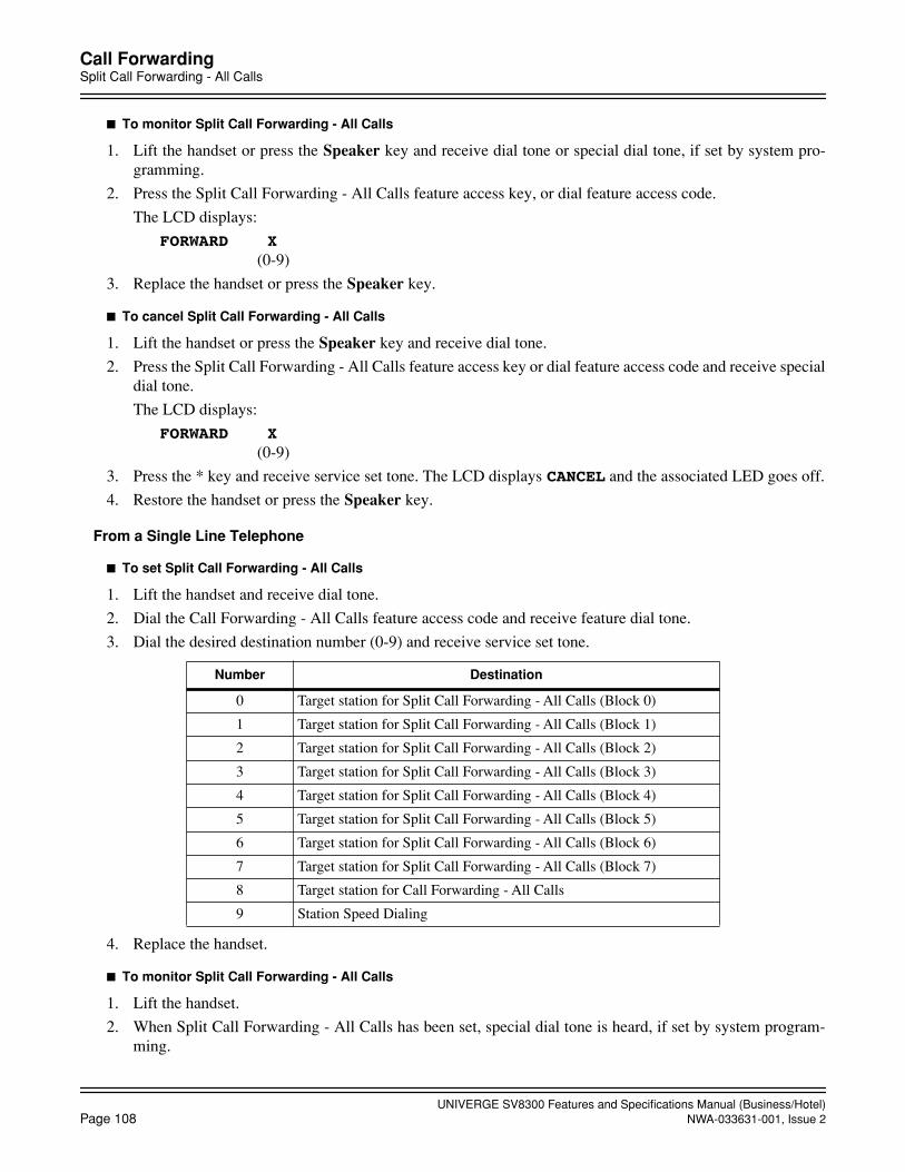
UNIVERGE SV8300 Features and Specifications Manual (Business/Hotel)Page 108 NWA-033631-001, Issue 2
Call ForwardingSplit Call Forwarding - All Calls
To monitor Split Call Forwarding - All Calls
1. Lift the handset or press the Speaker key and receive dial tone or special dial tone, if set by system pro-gramming.
2. Press the Split Call Forwarding - All Calls feature access key, or dial feature access code.
The LCD displays:
FORWARD X (0-9)
3. Replace the handset or press the Speaker key.
To cancel Split Call Forwarding - All Calls
1. Lift the handset or press the Speaker key and receive dial tone.
2. Press the Split Call Forwarding - All Calls feature access key or dial feature access code and receive specialdial tone.
The LCD displays:
FORWARD X (0-9)
3. Press the * key and receive service set tone. The LCD displays CANCEL and the associated LED goes off.
4. Restore the handset or press the Speaker key.
From a Single Line Telephone
To set Split Call Forwarding - All Calls
1. Lift the handset and receive dial tone.
2. Dial the Call Forwarding - All Calls feature access code and receive feature dial tone.
3. Dial the desired destination number (0-9) and receive service set tone.
4. Replace the handset.
To monitor Split Call Forwarding - All Calls
1. Lift the handset.
2. When Split Call Forwarding - All Calls has been set, special dial tone is heard, if set by system program-ming.
Number Destination
0 Target station for Split Call Forwarding - All Calls (Block 0)
1 Target station for Split Call Forwarding - All Calls (Block 1)
2 Target station for Split Call Forwarding - All Calls (Block 2)
3 Target station for Split Call Forwarding - All Calls (Block 3)
4 Target station for Split Call Forwarding - All Calls (Block 4)
5 Target station for Split Call Forwarding - All Calls (Block 5)
6 Target station for Split Call Forwarding - All Calls (Block 6)
7 Target station for Split Call Forwarding - All Calls (Block 7)
8 Target station for Call Forwarding - All Calls
9 Station Speed Dialing

UNIVERGE SV8300 Features and Specifications Manual (Business/Hotel)NWA-033631-001, Issue 2 Page 109
Call ForwardingSplit Call Forwarding - All Calls
3. Replace the handset.
To cancel Split Call Forwarding - All Calls
1. Lift the handset and receive dial tone.
2. Dial the Split Call Forwarding - All Calls cancellation code and receive service set tone.
3. Replace the handset.
Service Conditions
1. This feature allows a station to set the two kinds of call forwarded stations. One is the target station assignedfor Call Forwarding - All Calls, the other is the target station assigned for Split Call Forwarding - All Calls.The target stations for Split Call Forwarding are assigned in system programming.
2. Either Call Forwarding - All Calls or Split Call Forwarding - All Calls can be selected for the feature avail-able per tenant in system programming, depending on the type of the incoming call that is an internal call/attendant assisted call, a Tie Line call, or a C.O. call, and whether it is terminated internally or via CCIS.
3. Split Call Forwarding - All Calls allows any incoming Direct Inward Dialing (DID), Direct Inward Termi-nation (DIT), Tie Line, Transfer, and internal calls and calls via CCIS to be forwarded to a predeterminedlocation (Attendant Console, another station, or voice mail equipment).
4. When the station user that has set Split Call Forwarding lifts the handset, the station can receive special dialtone by system programming.
5. When Split Call Forwarding - All Calls is set, the trunk route is selectable by tenant of station set Call For-warding or tenant of the originating station/trunk.
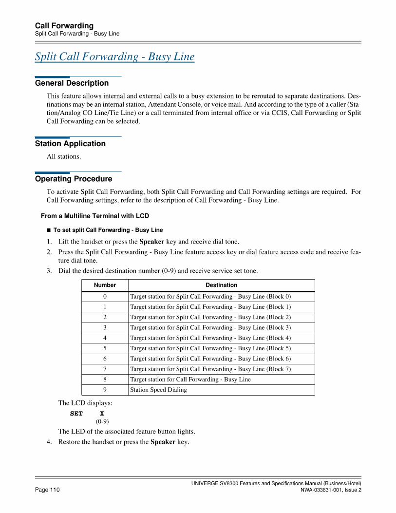
UNIVERGE SV8300 Features and Specifications Manual (Business/Hotel)Page 110 NWA-033631-001, Issue 2
Call ForwardingSplit Call Forwarding - Busy Line
Split Call Forwarding - Busy Line
General Description
This feature allows internal and external calls to a busy extension to be rerouted to separate destinations. Des-tinations may be an internal station, Attendant Console, or voice mail. And according to the type of a caller (Sta-tion/Analog CO Line/Tie Line) or a call terminated from internal office or via CCIS, Call Forwarding or SplitCall Forwarding can be selected.
Station Application
All stations.
Operating Procedure
To activate Split Call Forwarding, both Split Call Forwarding and Call Forwarding settings are required. ForCall Forwarding settings, refer to the description of Call Forwarding - Busy Line.
From a Multiline Terminal with LCD
To set split Call Forwarding - Busy Line
1. Lift the handset or press the Speaker key and receive dial tone.
2. Press the Split Call Forwarding - Busy Line feature access key or dial feature access code and receive fea-ture dial tone.
3. Dial the desired destination number (0-9) and receive service set tone.
The LCD displays:
SET X(0-9)
The LED of the associated feature button lights.
4. Restore the handset or press the Speaker key.
Number Destination
0 Target station for Split Call Forwarding - Busy Line (Block 0)
1 Target station for Split Call Forwarding - Busy Line (Block 1)
2 Target station for Split Call Forwarding - Busy Line (Block 2)
3 Target station for Split Call Forwarding - Busy Line (Block 3)
4 Target station for Split Call Forwarding - Busy Line (Block 4)
5 Target station for Split Call Forwarding - Busy Line (Block 5)
6 Target station for Split Call Forwarding - Busy Line (Block 6)
7 Target station for Split Call Forwarding - Busy Line (Block 7)
8 Target station for Call Forwarding - Busy Line
9 Station Speed Dialing

UNIVERGE SV8300 Features and Specifications Manual (Business/Hotel)NWA-033631-001, Issue 2 Page 111
Call ForwardingSplit Call Forwarding - Busy Line
To monitor Split Call Forwarding - Busy Line
1. Lift the handset or press the Speaker key and receive dial tone or special dial tone if set by system program-ming.
2. Press the Split Call Forwarding - Busy Line feature access key or dial feature access code.
The LCD displays:
FORWARD X(0-9)
3. Replace the handset or press the Speaker key.
To cancel Split Call Forwarding - Busy Line
1. Lift the handset or press the Speaker key and receive dial tone or special dial tone is heard if set by systemprogramming.
2. Press the Call Forwarding - Busy Line feature access key or dial feature access code and receive special dialtone if set by system programming. Press the * key and receive service set tone. The LCD displays CANCELand the associated LED goes off.
3. Restore the handset or press the Speaker key.
From a Single Line Telephone
To set Split Call Forwarding - Busy Line
1. Lift the handset and receive dial tone.
2. Dial the Call Forwarding - Busy Line feature access code and receive feature dial tone.
3. Dial destination number (0-9) and receive service set tone.
4. Replace the handset.
To monitor Split Call Forwarding - Busy Line
1. Lift the handset.
2. When Split Call Forwarding - Busy Line has been set, special dial tone is heard if set by system program-ming.
3. Replace the handset.
Number Destination
0 Target station for Split Call Forwarding - Busy Line (Block 0)
1 Target station for Split Call Forwarding - Busy Line (Block 1)
2 Target station for Split Call Forwarding - Busy Line (Block 2)
3 Target station for Split Call Forwarding - Busy Line (Block 3)
4 Target station for Split Call Forwarding - Busy Line (Block 4)
5 Target station for Split Call Forwarding - Busy Line (Block 5)
6 Target station for Split Call Forwarding - Busy Line (Block 6)
7 Target station for Split Call Forwarding - Busy Line (Block 7)
8 Target station for Call Forwarding - Busy Line
9 Station Speed Dialing

UNIVERGE SV8300 Features and Specifications Manual (Business/Hotel)Page 112 NWA-033631-001, Issue 2
Call ForwardingSplit Call Forwarding - Busy Line
To cancel Split Call Forwarding - Busy Line
1. Lift the handset and receive dial tone.
2. Dial Call Forwarding - Busy Line cancellation code and receive service set tone.
3. Replace the handset.
Service Conditions
1. This feature allows a station to set the two kinds of call forwarded stations. One is the target station assignedfor Call Forwarding - Busy Line, the other is the target station assigned for Split Call Forwarding - BusyLine. The target stations for Split Call Forwarding are assigned in system programming.
2. Either Call Forwarding - Busy Line or Split Call Forwarding - Busy Line can be selected for the featureavailable per tenant in system programming, depending on the type of the incoming call that is an internalcall/attendant assisted call, a Tie Line call, or a C.O. call, and whether it is terminated internally or via CCIS.
3. Split Call Forwarding - Busy Line allows any incoming Direct Inward Dialing (DID), Direct Inward Ter-mination (DIT), Tie Line, Transfer, and internal calls or calls via CCIS, which encounter a busy condition,to be forwarded to a predetermined location (Attendant Console, another station, or voice mail equipment).
4. Split Call Forwarding - Busy Line and Split Call Forwarding - No Answer must be set to the same destina-tion to result in Split Call Forwarding - Busy Line/No Answer.
5. When Split Call Forwarding - Busy Line is set, the trunk route is selectable by tenant of station set CallForwarding or tenant of the originating station/trunk.

UNIVERGE SV8300 Features and Specifications Manual (Business/Hotel)NWA-033631-001, Issue 2 Page 113
Call ForwardingSplit Call Forwarding - No Answer
Split Call Forwarding - No Answer
General Description
This feature allows internal and external calls, to extensions that do not answer, to be rerouted to separate des-tinations individually. And according to the type of a caller (Station/Analog CO Line/Tie Line) or a call termi-nated from internal office or via CCIS, Call Forwarding or Split Call Forwarding can be selected.
Station Application
All stations.
Operating Procedure
To activate Split Call Forwarding, both Split Call Forwarding and Call Forwarding settings are required. ForCall Forwarding settings, refer to the description of Call Forwarding - No Answer.
From a Multiline Terminal with LCD
To set split Call Forwarding - No Answer
1. Lift the handset or press the Speaker key and receive dial tone.
2. Press the Split Call Forwarding - No Answer feature access key or dial feature access code and receive fea-ture dial tone.
3. Dial the desired destination number (0-9) and receive service set tone.
The LCD displays:
FORWARD X (0-9)
4. Replace the handset or press the Speaker key.
To monitor Split Call Forwarding - No Answer
1. Lift the handset or press the Speaker key and receive dial tone or special dial tone if set by system program-ming.
Number Destination
0 Target station for Split Call Forwarding - No Answer (Block 0)
1 Target station for Split Call Forwarding - No Answer (Block 1)
2 Target station for Split Call Forwarding - No Answer (Block 2)
3 Target station for Split Call Forwarding - No Answer (Block 3)
4 Target station for Split Call Forwarding - No Answer (Block 4)
5 Target station for Split Call Forwarding - No Answer (Block 5)
6 Target station for Split Call Forwarding - No Answer (Block 6)
7 Target station for Split Call Forwarding - No Answer (Block 7)
8 Target station for Call Forwarding - No Answer
9 Station Speed Dialing

UNIVERGE SV8300 Features and Specifications Manual (Business/Hotel)Page 114 NWA-033631-001, Issue 2
Call ForwardingSplit Call Forwarding - No Answer
2. Press the Split Call Forwarding - No Answer feature access key or dial feature access code. The LCD displays:
FORWARD X(0-9)
3. Replace the handset or press the Speaker key.
To cancel Split Call Forwarding - No Answer
1. Lift the handset or press the Speaker key and receive dial tone.
2. Press the Split Call Forwarding - No Answer feature access key and receive special dial tone. Press the *key and receive service set tone. The LCD displays CANCEL and the associated LED goes off.
3. Replace the handset or press the Speaker key.
From a Single Line Telephone
To set Split Call Forwarding - No Answer
1. Lift the handset and receive dial tone.
2. Dial the Split Call Forwarding - No Answer feature access code and receive feature dial tone.
3. Dial desired destination number (0-9) and receive service set tone.
4. Replace the handset.
To monitor Split Call Forwarding - No Answer
1. Lift the handset.
2. When Split Call Forwarding - No Answer has been set, special dial tone is heard if set by system program-ming.
3. Replace the handset.
To cancel Split Call Forwarding - No Answer
1. Lift the handset and receive dial tone.
2. Dial the specific Split Call Forwarding - No Answer cancellation code and receive service set tone.
3. Replace the handset.
Number Destination
0 Target station for Split Call Forwarding - No Answer (Block 0)
1 Target station for Split Call Forwarding - No Answer (Block 1)
2 Target station for Split Call Forwarding - No Answer (Block 2)
3 Target station for Split Call Forwarding - No Answer (Block 3)
4 Target station for Split Call Forwarding - No Answer (Block 4)
5 Target station for Split Call Forwarding - No Answer (Block 5)
6 Target station for Split Call Forwarding - No Answer (Block 6)
7 Target station for Split Call Forwarding - No Answer (Block 7)
8 Target station for Call Forwarding - No Answer
9 Station Speed Dialing

UNIVERGE SV8300 Features and Specifications Manual (Business/Hotel)NWA-033631-001, Issue 2 Page 115
Call ForwardingSplit Call Forwarding - No Answer
Service Conditions
1. This feature allows a station to set the two kinds of call forwarded stations. One is the target station assignedfor Call Forwarding - No Answer, the other is the target station assigned for Split Call Forwarding - NoAnswer. The target stations for Split Call Forwarding are assigned in system programming.
2. Either Call Forwarding - No Answer or Split Call Forwarding - No Answer can be selected for the featureavailable per tenant in system programming, depending on the type of the incoming call that is an internalcall/attendant assisted call, a Tie Line call, or a C.O. call, and whether it is terminated internally or via CCIS.
3. Split Call Forwarding - No Answer allows any incoming Direct Inward Dialing (DID), Direct Inward Ter-mination (DIT), Tie Line, Transfer, and internal calls and calls via CCIS, which encounter a no-answer con-dition, to be forwarded to a predetermined location (Attendant Console, another station, or voice mailequipment).
4. Split Call Forwarding - Busy Line and Split Call Forwarding - No Answer must be set to the same destina-tion to result in Split Call Forwarding - Busy Line/No Answer.
5. When Split Call Forwarding - No Answer is set, the trunk route is selectable by tenant of the station set CallForwarding or tenant of the originating station/trunk.
UNIVERGE SV8300 Features and Specifications Manual (Business/Hotel)Page 116 NWA-033631-001, Issue 2
October, 2008
Call ForwardingCall Forwarding - Logout
Call Forwarding - Logout
General Description
This feature allows a call terminated to an IP station in logout status to be forwarded to a predesignated station,outside number, Attendant Console or VRS. This feature is also applicable to the IP stations that the LAN cableis pulled out or the power is off.
Station Application
IP Multiline Terminal, Soft Phone
Operating Procedure
Call Forwarding to a station
To set Call Forwarding - Logout
1. Press Speaker Key and receive dial tone.
2. Dial Call Forwarding - Logout Feature Access Code and receive special dial tone.
3. Dial a desired station number.
4. “Set OK” is displayed and receive service set tone.
5. Press Speaker Key.
To Cancel Call Forwarding - Logout
1. Press Speaker Key and receive dial tone.
2. Dial Call Forwarding - Logout Feature Cancellation Code and receive special dial tone.
3. Call forwarding destination is displayed.
4. Press *.
5. “Reset OK” is displayed and receive service set tone.
6. Press Speaker Key.
Call Forwarding to an outside number
To set Call Forwarding - Logout
1. Press Speaker Key and receive dial tone.
2. Dial Call Forwarding - Logout Feature Access Code and receive special dial tone.
3. Dial trunk access code and desired outside number.
4. “Set OK” is displayed and receive service set tone.
5. Press Speaker Key.
To Cancel Call Forwarding - Logout
1. Press Speaker Key and receive dial tone.
2. Dial Call Forwarding - Logout Feature Cancellation Code and receive special dial tone.
3. Call forwarding destination is displayed.

UNIVERGE SV8300 Features and Specifications Manual (Business/Hotel)NWA-033631-001, Issue 2 Page 117
October, 2008
Call ForwardingCall Forwarding - Logout
4. Press *.
5. “Reset OK” is displayed and receive service set tone.
6. Press Speaker Key.
Call Forwarding to Attendant Console
To set Call Forwarding - Logout
1. Press Speaker Key and receive dial tone.
2. Dial Call Forwarding - Logout Feature Access Code and receive special dial tone.
3. Dial Access Code for Attendant Console.
4. “Set OK” is displayed and receive service set tone.
5. Press Speaker Key.
To Cancel Call Forwarding - Logout
1. Press Speaker Key and receive dial tone.
2. Dial Call Forwarding - Logout Feature Cancellation Code and receive special dial tone.
3. Attendant Console for Call forwarding destination is displayed.
4. Press *.
5. “Reset OK” is displayed and receive service set tone.
6. Press Speaker Key.
Service Conditions
1. This feature is available for IP stations. The IP station means an IP Multiline Terminal (including SIP Mul-tiline Terminal and Soft Phone).
2. This feature is effective when an IP station is in the following logout conditions.
• When the IP station is logged out by Logout Feature Access Code.
• When Login Dialog is displayed on the IP station.
• When “Connecting.. ” is displayed on an IP station.
• When the IP station is reset by pulling out the LAN cable. (When the LAN cable is pulled out for morethan two minutes, the IP station is automatically reset.)
• When the power of the IP station is OFF.
• When the PBX system is reset by power failure or other reasons.
3. When an IP station is in a Logout status, calls cannot be terminated to the sublines on that IP station,
4. When an IP station in a Logout status is in a multiline group, a call to that IP station cannot ring other sta-tions in that multiline group.
5. A call forwarding destination can be a station, a Voice Mail, an outside number, an Attendant Console, anda VRS.
6. When the call forwarding destination is a station, an outside number or an Attendant Console, this featurecan be set by dialing Call Forwarding - Logout Feature Access /Cancellation Code or data assignment froma PCPro/CAT. Setting by Feature Access Key is not supported.

UNIVERGE SV8300 Features and Specifications Manual (Business/Hotel)Page 118 NWA-033631-001, Issue 2
Call ForwardingCall Forwarding - Logout
7. When the call forwarding destination is an outside number, there are following conditions.
a. When an IP station in a Logout status receives an incoming trunk call and call forwarding destination is an outside number (tandem connection), the call is forwarded or not in accordance with the restriction data for tandem connections. When the tandem connection between the incoming trunk route and outgoing trunk route is allowed by system programming, the call is forwarded to the outside number. When it is restricted, the caller will hear ROT.
b. Maximum 250 outside numbers can be assigned as call forwarding destinations. (There is nolimitation when a station is designated as a call forwarding destination.)
c. Whether an IP station is busy or not, the PCPro/CAT can set/change the Call Forwarding - Logoutdestination.
d. When a toll call number is assigned as the call forwarding destination, a calling station that isrestricted to make a toll call can be forwarded to that toll call number.
8. When the call forwarding destination is a VRS, this feature can be assigned on a tenant basis by system pro-gramming. However, the call forwarding destination assigned by Feature Access Code or PC Programming/CAT (station, outside number, Attendant Console) has priority over that assigned by the system data VRS.Up to 8 multi-connections are available per VRS. When the connection exceeds 8, the excess connectionsare restricted and the caller will hear ROT. Secondary callers cannot be connected to the beginning of themessage. A message duration for the announcement is assigned by system data. When the message durationexceeds the time assigned by the system programming, the caller will hear ROT.
9. When the call forwarding destination is not assigned, a caller will hear ROT or RBT.
If the called IP station sets Call Forwarding - All Calls, the caller will be forwarded to the destination ofCall Forwarding - All Calls. Even if the called IP station sets any of Call Forwarding - Busy Line, Call For-warding - No Answer, Do Not Disturb and Station Hunting, such service will be ignored and the caller willhear ROT or RBT. ROT or RBT can be selected in station class of Service assignment.
10. Figure below shows a service priority applied to a IP Multiline Terminal (SIP) that sets more than one callforwarding or hunting features at the same time are set. Call Forwarding - Logout, Call Forwarding - AllCalls, Do Not Disturb, Uniform Call Distribution(UCD), Station Hunting, Call Forwarding - Busy Line,Call Forwarding - No Answer are listed in the order of priority. Note that when the IP Multiline Terminal(SIP) in the logout status does not set both Call Forwarding - Logout and Call Forwarding - All Calls, thecaller will not be forwarded by UCD, Do Not Disturb, Station Hunting, Call Forwarding - Busy Line, orCall Forwarding - No Answer and will hear ROT or RBT.
Service Priority in Logout Status
11. Call Forwarding - Logout service can be allowed or deniedin Class of Service assignment. Also, ROT/RBT, which calling party hears when call forwarding destination is not assigned, can be selected in Classof Service assignment.
High
Low
Call Forwarding - Logout
Call Forwarding - All Calls
Do Not Disturb
UCD
Station Hunting
Call Forwarding - Busy Line
Call Forwarding - No Answer
Priority
Note: When neither Call For-warding - Logout nor CallForwarding - All Calls isset:, the caller will hearROT/RBT.
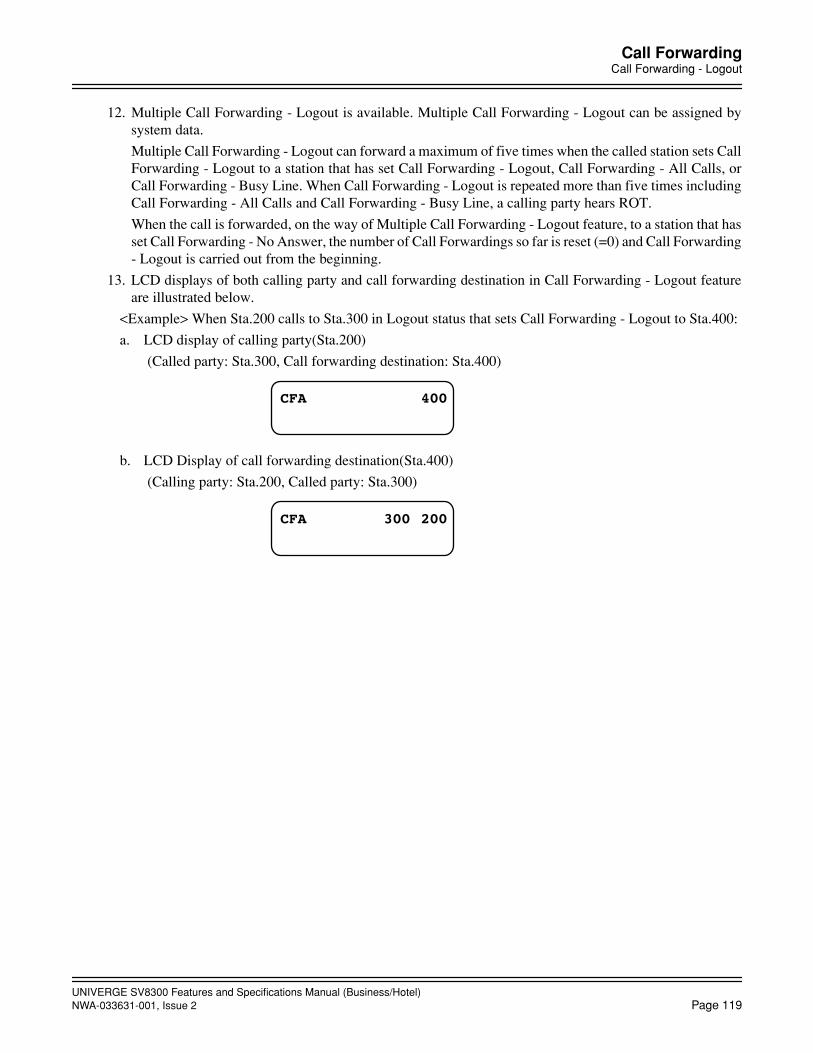
UNIVERGE SV8300 Features and Specifications Manual (Business/Hotel)NWA-033631-001, Issue 2 Page 119
Call ForwardingCall Forwarding - Logout
12. Multiple Call Forwarding - Logout is available. Multiple Call Forwarding - Logout can be assigned bysystem data.
Multiple Call Forwarding - Logout can forward a maximum of five times when the called station sets CallForwarding - Logout to a station that has set Call Forwarding - Logout, Call Forwarding - All Calls, orCall Forwarding - Busy Line. When Call Forwarding - Logout is repeated more than five times includingCall Forwarding - All Calls and Call Forwarding - Busy Line, a calling party hears ROT.
When the call is forwarded, on the way of Multiple Call Forwarding - Logout feature, to a station that hasset Call Forwarding - No Answer, the number of Call Forwardings so far is reset (=0) and Call Forwarding- Logout is carried out from the beginning.
13. LCD displays of both calling party and call forwarding destination in Call Forwarding - Logout featureare illustrated below.
<Example> When Sta.200 calls to Sta.300 in Logout status that sets Call Forwarding - Logout to Sta.400:
a. LCD display of calling party(Sta.200)
(Called party: Sta.300, Call forwarding destination: Sta.400)
b. LCD Display of call forwarding destination(Sta.400)
(Calling party: Sta.200, Called party: Sta.300)
CFA 400
CFA 200300

UNIVERGE SV8300 Features and Specifications Manual (Business/Hotel)Page 120 NWA-033631-001, Issue 2
Call ForwardingCall Forwarding - Override
Call Forwarding - Override
General Description
This feature allows the call forward destination station to call the station that set call forward. The call forwardsetting will be ignored.
Station Application
All stations.
Operating Procedure
Normal call handling procedures apply.
Service Conditions
1. This feature is allowed to all stations and the Attendant Console.
2. This feature is activated when the call forward destination station calls the station using My Line. A callusing Sub Line can override only when the called station sets Call Forwarding - All Calls or Split Call For-warding - All Calls, by system programming.
3. If the calling station is set as the forwarded destination of its own call in multiple call forwarding scheme,the call can override in the same manner as described in Service Condition 2. above.
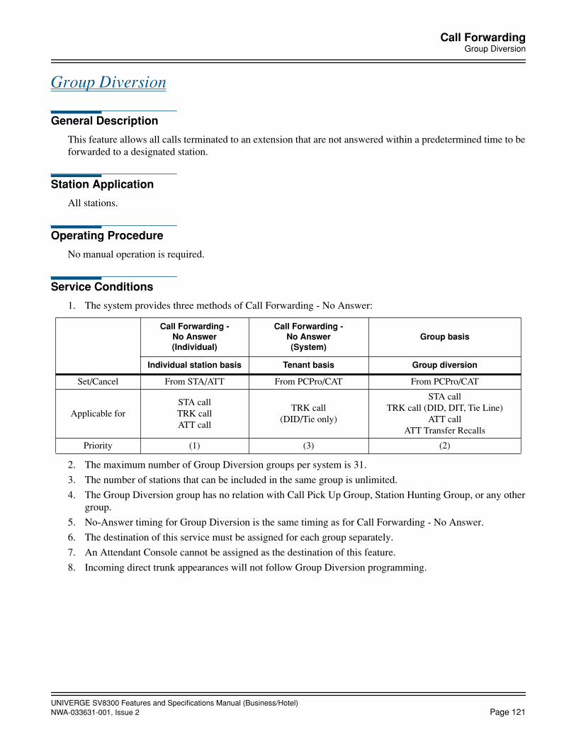
UNIVERGE SV8300 Features and Specifications Manual (Business/Hotel)NWA-033631-001, Issue 2 Page 121
Call ForwardingGroup Diversion
Group Diversion
General Description
This feature allows all calls terminated to an extension that are not answered within a predetermined time to beforwarded to a designated station.
Station Application
All stations.
Operating Procedure
No manual operation is required.
Service Conditions
1. The system provides three methods of Call Forwarding - No Answer:
2. The maximum number of Group Diversion groups per system is 31.
3. The number of stations that can be included in the same group is unlimited.
4. The Group Diversion group has no relation with Call Pick Up Group, Station Hunting Group, or any othergroup.
5. No-Answer timing for Group Diversion is the same timing as for Call Forwarding - No Answer.
6. The destination of this service must be assigned for each group separately.
7. An Attendant Console cannot be assigned as the destination of this feature.
8. Incoming direct trunk appearances will not follow Group Diversion programming.
Call Forwarding -No Answer(Individual)
Call Forwarding -No Answer(System)
Group basis
Individual station basis Tenant basis Group diversion
Set/Cancel From STA/ATT From PCPro/CAT From PCPro/CAT
Applicable forSTA callTRK callATT call
TRK call(DID/Tie only)
STA callTRK call (DID, DIT, Tie Line)
ATT callATT Transfer Recalls
Priority (1) (3) (2)

UNIVERGE SV8300 Features and Specifications Manual (Business/Hotel)Page 122 NWA-033631-001, Issue 2
Call History
Call History
General Description
This feature allows a Multiline Terminal to display Outgoing and Incoming Call History.
Outgoing Call History (previously known as “Stack Dial”) allows a Multitiline Terminal user to quickly re-dial the last 10 numbers dialed. The user can redial from the call history and erase the call history data fromsystem memory.
Incoming Call History (previously known as “CID Call Back”) allows a Multitiline Terminal user to displayIncoming Call History, which is a list of incoming caller’s telephone numbers with date and time stamp. In-coming Call History saves up to the last 50 numbers per Multiline Terminal (10 numbers in default) and up to32,000 numbers per system. The user can call back from the call history and erase the call history data fromsystem memory. Missed call indication is provided by Message Waiting LED and Missed Call Icon (DT750, DT730 and DT330 only).
Note: This is a UNIVERGE SV8300 system feature. A built-in Call History feature of the DT700 and DT300 can-not be used in the SV8300. “Add call history data to telephone directory” is not provided by the SV8300.
Service Conditions
1. Feature dial tone (special dial tone) is not provided during the operations.
2. If there is no operation in 30 seconds while the stored number is displayed, the Multiline Terminal will re-turn to an idle state.
3. When the Exit key is pressed at any time during the operations, the Multiline Terminal will return to an idlestate.
4. The stored number is not displayed when the Multiline Terminal LCD (the second line from the bottom) isused for OAI applications.
5. Set Relocation feature can swap the call history data.
Multi UNITs (or Remote UNITs) in a Survival Mode
When a UNIT is in the Survival Mode, The Multiline Terminals in the UNIT may not display the latest callhistory data with the following reasons.
• The call history data is normally saved in system memory of UNIT #1. This data is copied from UNIT #1 to other UNITs once a day at a pre-programmed time, together with system data, for backup. If a UNIT other than UNIT #1 enters a Survival Mode, the Multiline Terminals in the UNIT display the backup call history data, not the data in UNIT #1. For example, if system data copy is programmed to execute at 02:00 and UNIT #2 enters a Survival Mode at 14:00, the Multiline Terminals in UNIT #2 display the call history data at 02:00. The call history data just before 14:00 cannot be displayed during the Survival Mode.
• During the Survival Mode, new call history for following calls are saved in system memory of the UNIT in the Survival Mode.
- Outgoing calls from Multiline Terminals in the UNIT
- Incoming calls from stations/trunks within the UNIT

UNIVERGE SV8300 Features and Specifications Manual (Business/Hotel)NWA-033631-001, Issue 2 Page 123
Call HistoryIncoming Call History (CID Call Back)
• During the Survival Mode, new call history for following calls are saved in system memory of UNIT #1.
- Incoming calls from stations/trunks in other UNITs to Multiline Terminals in the UNIT in the Sur-vival Mode
• If an incoming call is terminated by the “Backup Call Routing to ISDN” feature, calling party number is displayed on the Multiline Terminal, but not saved in the incoming call history.
• After the UNIT returns to a normal operating mode, the Multiline Terminals in the UNIT display the call history data saved in UNIT #1. The added call history data in the UNIT which was in the Survival Mode is erased and the data in UNIT #1 is copied to the UNIT.
Incoming Call History (CID Call Back)
General Description
This feature allows a Multitiline Terminal user to display Incoming Call History, which is a list of incomingcaller’s telephone numbers with date and time stamp. Incoming Call History saves in system memory up to thelast 50 numbers per Multiline Terminal (10 numbers in default) and up to 32,000 numbers per system. The sys-tem remembers the digits regardless of whether the call was answered or unanswered. When an unansweredcall (missed call) is saved, a Message Waiting LED will turn on and Missed Call Icon is displayed. Pressingthe softkey, Cursor key or Volume key will scroll through the Incoming Call History. The user can call backto the number from the Incoming Call History menu.
Station Application
All Multiline Terminals with LCD
Missed Call Icon can be displayed on the following telephones; DT750, DT730 and DT330.
Operating Procedure
To display and call back to the number for Missed Calls
1. Press the Cursor (Enter) key. The Shortcut Menu is displayed.
=> The number of Missed Calls is displayed for DT330 (“1. Missed Calls: 003” is displayed if there are 3missed calls).

UNIVERGE SV8300 Features and Specifications Manual (Business/Hotel)Page 124 NWA-033631-001, Issue 2
Call HistoryIncoming Call History (CID Call Back)
2. Select “1. Missed Calls” by pressing 1.
=> You can press the OK softkey or Cursor (Enter) key, instead.
The LCD displays: “<MISSED>” followed by caller’s number for the last missed call with date and timestamp.
3. To call back to the displayed number, press the CB softkey or Cursor (Enter) key.
- OR -
4. Search for other missed calls by pressing the ↓Next (or↑Prev) softkey (or Cursor key.). To call back to the displayed number, press the CB softkey or Cursor (Enter) key.
5. The system automatically dials the number displayed on the LCD.
=> After the call back, the call history for that number is not erased from system memory until the deleteoperation is done.
=> Next time you access to the call history which has already called back, the LCD displays “<CB>” fol-lowed by caller’s number with date and time stamp (CB = Called Back).
=> Message Waiting LED will turn off if all the missed calls are checked (displayed).
=> Missed Call Icon will disappear if all the missed calls are erased from the call history.
To display and call back to the number from All Incoming Call History
Access from the HIST. softkey
1. Press the HIST. softkey. The Call History menu is displayed.
2. Press the IC softkey (or Cursor s key). The last caller’s number is displayed.
3. Follow the operating procedure of To display and call back to the number for Missed Calls (from Step3).
Access from the Menu key
DT700
1. Press the Menu key. The Top Menu is displayed.
2. Select “1. History” by pressing 1. The Call History menu is displayed.
=> You can press the OK softkey or Cursor (Enter) key, instead.
3. Press the IC softkey (or Cursor s key). The last caller’s number is displayed.
4. Follow the operating procedure of To display and call back to the number for Missed Calls (from Step 3).
UNIVERGE SV8300 Features and Specifications Manual (Business/Hotel)NWA-033631-001, Issue 2 Page 125
Call HistoryIncoming Call History (CID Call Back)
DT300
1. Press the Menu key. The Top Menu is displayed.
2. Select “1. Call History” by pressing 1. The last caller’s number is displayed.
=> You can press the OK softkey or Cursor (Enter) key, instead.
3. Select “1. Incoming Calls” by pressing 1.
=> You can press the OK softkey or Cursor (Enter) key, instead.
4. Follow the operating procedure of To display and call back to the number for Missed Calls (from Step3).
To delete the stored number(s)
1. During the stored number is displayed, press <<<< softkey (or Cursor tttt key, if equipped).
2. To delete the number, press the Del softkey. The number displayed on the LCD is deleted from the CallHistory memory.
- OR -
2. To delete all the stored numbers from the Call History memory, press the DelAll softkey. “Delete All History: OK?” is displayed for confirmation.
=> If you want to cancel the deletion, press the Cancel softkey.
3. To delete the numbers, press the OK softkey. “Delete Complete” is displayed. All the stored numbers aredeleted from the Call History memory
Service Conditions
1. Incoming Call History saves up to the last 50 numbers can be stored per station (10 numbers as default) andup to the last 32,000 numbers per system. The maximum number of call history saved per station can beassigned by system programming.
2. When the call history memory is full and a new number is received, the oldest stored number is deleted andthe new number is stored.
3. Incoming Call History saves in system memory up to 16 digits. If system reset occurs, the call history datacannot be saved.
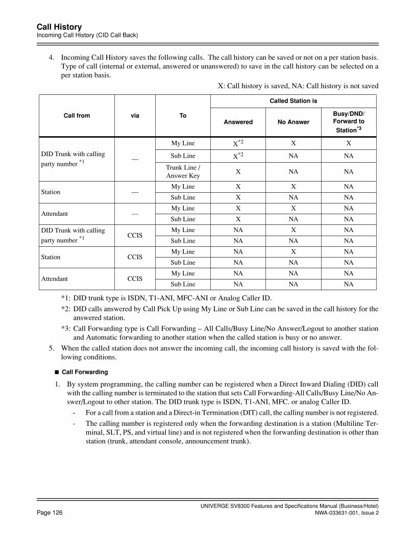
UNIVERGE SV8300 Features and Specifications Manual (Business/Hotel)Page 126 NWA-033631-001, Issue 2
Call HistoryIncoming Call History (CID Call Back)
4. Incoming Call History saves the following calls. The call history can be saved or not on a per station basis.Type of call (internal or external, answered or unanswered) to save in the call history can be selected on aper station basis.
X: Call history is saved, NA: Call history is not saved
*1: DID trunk type is ISDN, T1-ANI, MFC-ANI or Analog Caller ID.
*2: DID calls answered by Call Pick Up using My Line or Sub Line can be saved in the call history for theanswered station.
*3: Call Forwarding type is Call Forwarding – All Calls/Busy Line/No Answer/Logout to another stationand Automatic forwarding to another station when the called station is busy or no answer.
5. When the called station does not answer the incoming call, the incoming call history is saved with the fol-lowing conditions.
Call Forwarding
1. By system programming, the calling number can be registered when a Direct Inward Dialing (DID) callwith the calling number is terminated to the station that sets Call Forwarding-All Calls/Busy Line/No An-swer/Logout to other station. The DID trunk type is ISDN, T1-ANI, MFC. or analog Caller ID.
- For a call from a station and a Direct-in Termination (DIT) call, the calling number is not registered.
- The calling number is registered only when the forwarding destination is a station (Multiline Ter-minal, SLT, PS, and virtual line) and is not registered when the forwarding destination is other thanstation (trunk, attendant console, announcement trunk).
Call from via To
Called Station is
Answered No AnswerBusy/DND/Forward to
Station*3
DID Trunk with calling
party number *1 ---
My Line X*2 X X
Sub Line X*2 NA NA
Trunk Line / Answer Key
X NA NA
Station ---My Line X X NA
Sub Line X NA NA
Attendant ---My Line X X NA
Sub Line X NA NA
DID Trunk with calling
party number *1 CCISMy Line NA X NA
Sub Line NA NA NA
Station CCISMy Line NA X NA
Sub Line NA NA NA
Attendant CCISMy Line NA NA NA
Sub Line NA NA NA
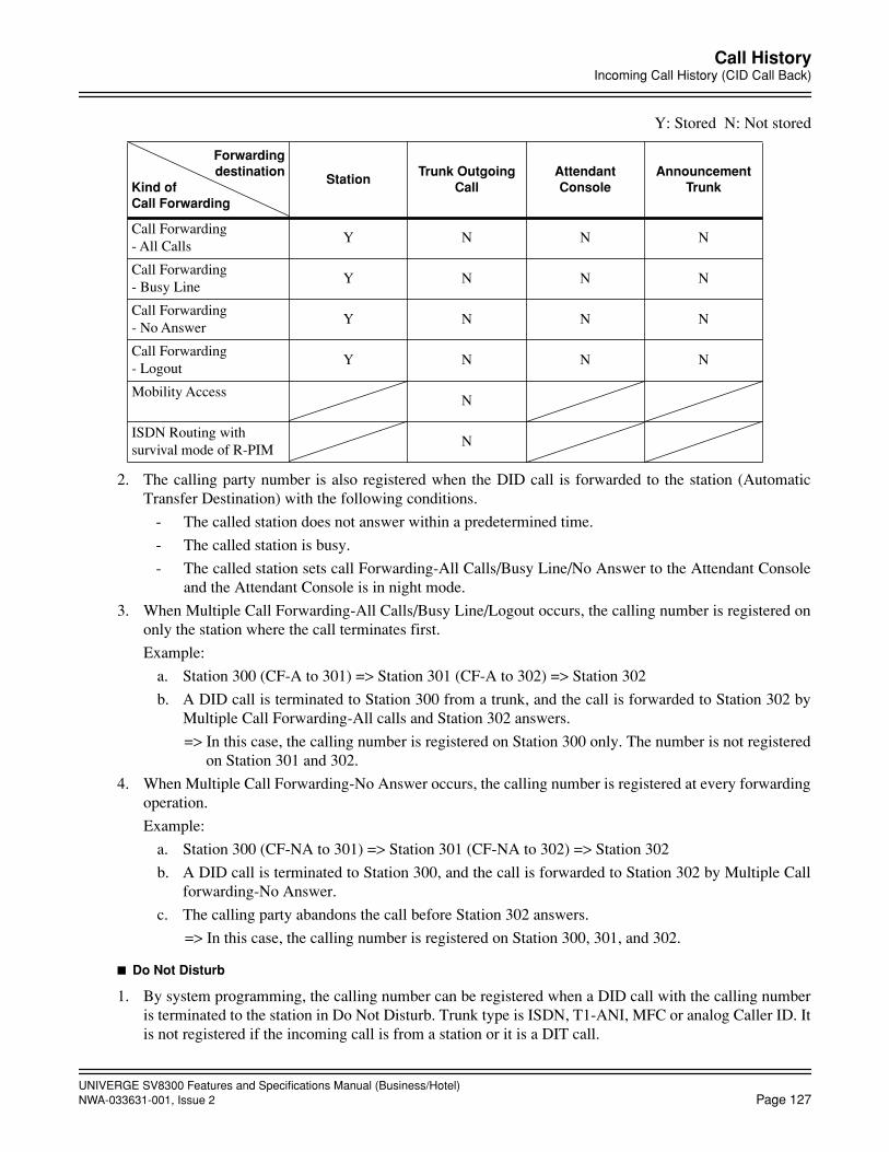
UNIVERGE SV8300 Features and Specifications Manual (Business/Hotel)NWA-033631-001, Issue 2 Page 127
Call HistoryIncoming Call History (CID Call Back)
Y: Stored N: Not stored
2. The calling party number is also registered when the DID call is forwarded to the station (AutomaticTransfer Destination) with the following conditions.
- The called station does not answer within a predetermined time.
- The called station is busy.
- The called station sets call Forwarding-All Calls/Busy Line/No Answer to the Attendant Consoleand the Attendant Console is in night mode.
3. When Multiple Call Forwarding-All Calls/Busy Line/Logout occurs, the calling number is registered ononly the station where the call terminates first.
Example:
a. Station 300 (CF-A to 301) => Station 301 (CF-A to 302) => Station 302
b. A DID call is terminated to Station 300 from a trunk, and the call is forwarded to Station 302 byMultiple Call Forwarding-All calls and Station 302 answers.
=> In this case, the calling number is registered on Station 300 only. The number is not registeredon Station 301 and 302.
4. When Multiple Call Forwarding-No Answer occurs, the calling number is registered at every forwardingoperation.
Example:
a. Station 300 (CF-NA to 301) => Station 301 (CF-NA to 302) => Station 302
b. A DID call is terminated to Station 300, and the call is forwarded to Station 302 by Multiple Callforwarding-No Answer.
c. The calling party abandons the call before Station 302 answers.
=> In this case, the calling number is registered on Station 300, 301, and 302.
Do Not Disturb
1. By system programming, the calling number can be registered when a DID call with the calling numberis terminated to the station in Do Not Disturb. Trunk type is ISDN, T1-ANI, MFC or analog Caller ID. Itis not registered if the incoming call is from a station or it is a DIT call.
Forwardingdestination
Kind ofCall Forwarding
StationTrunk Outgoing
CallAttendant Console
Announcement Trunk
Call Forwarding - All Calls
Y N N N
Call Forwarding - Busy Line
Y N N N
Call Forwarding - No Answer
Y N N N
Call Forwarding - Logout
Y N N N
Mobility AccessN
ISDN Routing with survival mode of R-PIM
N
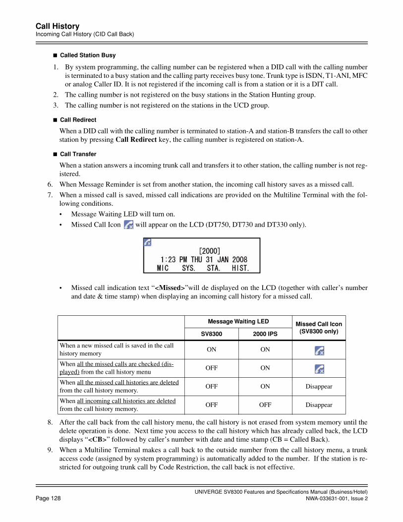
UNIVERGE SV8300 Features and Specifications Manual (Business/Hotel)Page 128 NWA-033631-001, Issue 2
Call HistoryIncoming Call History (CID Call Back)
Called Station Busy
1. By system programming, the calling number can be registered when a DID call with the calling numberis terminated to a busy station and the calling party receives busy tone. Trunk type is ISDN, T1-ANI, MFCor analog Caller ID. It is not registered if the incoming call is from a station or it is a DIT call.
2. The calling number is not registered on the busy stations in the Station Hunting group.
3. The calling number is not registered on the stations in the UCD group.
Call Redirect
When a DID call with the calling number is terminated to station-A and station-B transfers the call to otherstation by pressing Call Redirect key, the calling number is registered on station-A.
Call Transfer
When a station answers a incoming trunk call and transfers it to other station, the calling number is not reg-istered.
6. When Message Reminder is set from another station, the incoming call history saves as a missed call.
7. When a missed call is saved, missed call indications are provided on the Multiline Terminal with the fol-lowing conditions.
• Message Waiting LED will turn on.
• Missed Call Icon will appear on the LCD (DT750, DT730 and DT330 only).
• Missed call indication text “<Missed>”will de displayed on the LCD (together with caller’s numberand date & time stamp) when displaying an incoming call history for a missed call.
8. After the call back from the call history menu, the call history is not erased from system memory until thedelete operation is done. Next time you access to the call history which has already called back, the LCDdisplays “<CB>” followed by caller’s number with date and time stamp (CB = Called Back).
9. When a Multiline Terminal makes a call back to the outside number from the call history menu, a trunkaccess code (assigned by system programming) is automatically added to the number. If the station is re-stricted for outgoing trunk call by Code Restriction, the call back is not effective.
Message Waiting LED Missed Call Icon (SV8300 only)SV8300 2000 IPS
When a new missed call is saved in the call history memory
ON ON
When all the missed calls are checked (dis-played) from the call history menu
OFF ON
When all the missed call histories are deleted from the call history memory.
OFF ON Disappear
When all incoming call histories are deleted from the call history memory.
OFF OFF Disappear
UNIVERGE SV8300 Features and Specifications Manual (Business/Hotel)NWA-033631-001, Issue 2 Page 129
October, 2008
Call HistoryOutgoing Call History (Stack Dial)
Outgoing Call History (Stack Dial)
General Description
This feature allows a Multitiline Terminal user to quickly redial the last 10 numbers dialed. For example, a usermay quickly recall a busy or unanswered number without manually dialing the digits.
Outgoing Call History saves in system memory up to 32 digits a user dials. The number can be any combinationof digits 0~9, # and *. The system remembers the digits regardless of whether the call was answered, unan-swered or busy.
When pressing the Redial key, the display indicates “REDIAL [*/#]/SPEED[ ]”. The user can then press * or# to redial the number displayed, or enter an abbreviated code of Station Speed Dialing to be dialed. Pressingthe softkey, Cursor key, or Volume key will scroll through the Call History.
Station Application
All Multiline Terminals with LCD and Attendant Consoles.
Operating Procedure
To redial from Outgoing Call History
Access from the Redial key
1. Press the Redial key. The last dialed number is displayed.
2. To redial the last number, press the Redial softkey (or Cursor (Enter) key if equipped).
=> You can press * or #, instead.
- OR -Search for the desired number from the Redial List by pressing the ↓Next (or↑Prev) softkey (or Cursor key or Volume key, if equipped)Press the Redial softkey (or Cursor (Enter) key if equipped).
=> You can press * or #, instead.
3. The system automatically dials the number displayed on the LCD.
Access from the HIST. softkey
1. Press the HIST. softkey. The Call History menu is displayed.
2. Press the OG softkey. The last number dialed is displayed.
3. Follow the operating procedure of Access from the Redial key (from Step 2).
Access from the Menu key (if equipped)
DT700
1. Press the Menu key. The Top Menu is displayed.
2. Select “1. History” by pressing 1.
=> You can press the OK softkey or Cursor (Enter) key, instead.
The Call History menu is displayed.
UNIVERGE SV8300 Features and Specifications Manual (Business/Hotel)Page 130 NWA-033631-001, Issue 2
Call HistoryOutgoing Call History (Stack Dial)
3. Press the OG softkey. The last number dialed is displayed.
4. Follow the operating procedure of Access from the Redial key (from Step 2).
DT300
1. Press the Menu key. The Top Menu is displayed.
2. Select “1. Call History” by pressing 1.
=> You can press the OK softkey or Cursor (Enter) key, instead.
3. 3. Select “2. Outgoing Calls” by pressing 2 or the Cursor key. The last dialed number is displayed.
4. Follow the operating procedure of Access from the Redial key (from Step 2).
To delete the stored number(s)
1. During the stored number is displayed, press <<<< softkey (or Cursor t key if equipped).
2. To delete the number, press the Del softkey. The number displayed on the LCD is deleted from the CallHistory memory.
- OR -
1. To delete all the stored numbers from the Call History memory, press the DelAll softkey. “Delete All History: OK?” is displayed for confirmation.
=> If you want to cancel the deletion, press the Cancel softkey.
2. To delete the numbers, press the OK softkey. “Delete Complete” is displayed. All the stored numbers aredeleted from the Call History memory.
Service Conditions
1. The last 10 numbers dialed can be stored per station in a call history memory. When the call history memoryis full and a new number is dialed, the oldest stored number is deleted and the new number is stored.
2. Station and outside numbers dialed can be stored regardless of whether the call was answered, unansweredor busy. Feature access codes and dead numbers (numbers not exist) cannot be stored.
3. Outgoing Call History saves in system memory up to 32 digits a user dials. If system reset occurs, the callhistory data cannot be saved.
4. When redialing the number using the call history, the previous call history of that number is deleted and theredialed number is stored as a last dialed number in the call history.
5. Save and Repeat feature does not work during the stored number is displayed, but after the number is redi-aled.

UNIVERGE SV8300 Features and Specifications Manual (Business/Hotel)NWA-033631-001, Issue 2 Page 131
Call ParkCall Park - System
Call Park
General Description
This feature enables a station user or attendant to place a call into designated Call Park locations. The stationuser or attendant is then free to process other calls. This feature is available system wide and for individual ten-ants.
Call Park - System
General Description
When a call is parked by Call Park-System, the call can be retrieved from Call Park by any station in the system.
Station Application
All stations and Attendant Consoles.
Operating Procedure
To place a call into Call Park-System (by Call Park - System location number)
From a Single Line Telephone
1. Press the FLASH key (or momentarily press the hookswitch) and receive feature dial tone.
2. The call in progress is placed on Consultation Hold.
3. Dial the Call Park-System feature access code.
4. Dial the Call Park-System location number (00-19) and receive service set tone. (If the Call Park number isbusy, dial another location number using the Step Call feature until an idle park location is accessed).
5. Restore the handset.
From a Multiline Terminal with LCD
1. Press the Transfer key and receive feature dial tone.
2. The call in progress is placed on Consultation Hold.
3. Dial the Call Park-System feature access code. The first available Call Park location is selected by the sys-tem and displayed in the LCD. Receive service set tone.
4. Restore handset.
OR
1. Press the Call Park-System feature key and receive service set tone.
2. Restore the handset.
From a Multiline Terminal without LCD
1. Press the Transfer key and receive feature dial tone.

UNIVERGE SV8300 Features and Specifications Manual (Business/Hotel)Page 132 NWA-033631-001, Issue 2
Call ParkCall Park - System
2. The call in progress is placed on Consultation Hold.
3. Dial the Call Park-System feature access code, or press Call Park-System feature key.
4. Dial the Call Park location number (00-19) and receive service set tone. (If Call Park-System number isbusy, dial another location number using the Step Call feature until an idle park location is accessed.)
5. Restore the handset.
From an Attendant Console
1. Dial Call Park-System feature access code. The first available Call Park location is selected by the systemand displayed in the LCD. Receive service set tone.
2. Press the RELEASE Key.
To retrieve a call from Call Park-System (by Call Park - System location number)
From a Single Line Telephone
1. From any station, go off hook and receive internal dial tone.
2. Dial the Call Park-System retrieval access code.
3. Dial the Call Park-System location number (00-19).
4. Converse.
From a Multiline Terminal with a Trunk Direct Appearance
1. Go off hook and receive dial tone.
2. Press Trunk Direct Appearance feature key flashing.
From an Attendant Console
1. Press LOOP key.
2. Dial the Call Park-System feature access code or press the Call Park-System feature key.
3. Dial the Call Park-System location number (00-19).
4. Converse.
To place a call into Call Park-System (by station number)
From a Single Line Telephone
1. Press the FLASH key (or momentarily press the hookswitch) and receive feature dial tone.
2. The call in progress is placed on Consultation Hold.
3. Dial the Call Park-System feature access code, and receive service set tone.
4. Restore the handset.
From a Multiline Terminal with LCD
1. Press the Transfer key and receive feature dial tone.
2. The call in progress is placed on Consultation Hold.
3. Dial the Call Park-System feature access code or press Call park -Systemfeature key. The parked party number is displayed in the LCD. Receive service set tone.
4. Restore the handset.
UNIVERGE SV8300 Features and Specifications Manual (Business/Hotel)NWA-033631-001, Issue 2 Page 133
Call ParkCall Park - System
From a Multiline Terminal without LCD
1. Press the Transfer key and receive feature dial tone.
2. The call in progress is placed on Consultation Hold.
3. Dial the Call Park-System feature access code or press Call park -System feature key, and receive serviceset tone.
4. Restore the handset.
To retrieve a call from Call park-System (by station number)
From a Single Line Telephone or Multiline Terminal
1. From any station, go off hook and receive internal dial tone.
2. Dial the Call Park-System retrieval access code.
3. Dial the station number that set Call Park-System.
4. Converse.
Service Conditions
Call Park-System (by Call Park - System location number)
1. A station user can originate and receive calls while having a call in Call Park-System.
2. A maximum of 20 simultaneous calls can be parked within a system. A station user can place multiple callsinto Call Park-System provided the maximum number is not exceeded.
3. Any internal or external call can be placed into Call Park-System.
4. Any call left on Call Park-System for more than a programmed time interval will recall to the primary ex-tension of the station that originally parked the call. Once this recall has started, the Call Park-System loca-tion becomes idle. When Call Park-System recalls, the parked party hears ringback tone.
5. If the trunk that was placed in Call Park is assigned to any Multiline Terminal as a direct trunk appearance,the system can be programmed to allow the Multiline Terminal to retrieve the parked call by pressing theTrunk key. Trunk key LED indication is as follows:
• Possible to retrieve:flashing Green/Red (hold)
• Impossible to retrieve:steady Red (busy)
6. When a Call Park-System recalls to a station, any other station can pick it up using Call Pickup - Direct,Call Pickup - Group or Call Pickup - Designated Group.
7. When attempting to set Call Park-System to a busy Call Park-System location, Step Call can be used to ac-cess an idle location.
8. A call can be retrieved from Call Park-System while receiving feature dial tone.
9. If a station other than the station that originally parked the call retrieves the call, Station Message DetailRecording (SMDR) will record a transfer.
10. Parked calls receive Music On Hold, if provided.
11. When a Call Park-System recalls to an Attendant Console, no LED indication is provided. However, thecall park location will appear in the display.
12. No LED indication for the Call Park-System key on an Attendant Console is provided.

UNIVERGE SV8300 Features and Specifications Manual (Business/Hotel)Page 134 NWA-033631-001, Issue 2
Call ParkCall Park - System
Call Park-System (by station number)
1. A call can be parked into Call Park-System by the following terminals:
• Single line telephone
• Multiline Terminal
• PS
The Attendant Console and ISDN terminal cannot park the call in this feature.
2. A call can be retrieved from Call Park-System by the following terminals:
• Single line telephone
• Multiline Terminal
• PS
• Attendant Console
The ISDN terminal cannot retrieve the parked call in this feature.
3. A station user can originate and receive calls while having a call in Call Park-System.
4. A maximum of 20 simultaneous calls can be parked within a system. A station user can place only one callinto Call park-System.
5. An internal or external call can be placed into Call Park-System.
6. Any call left on Call park-System for more than a programmed time interval will recall to the primary ex-tension of the station that originally parked the call. When Call Park-System recalls, the parked party hearsringback tone.
7. If the trunk that was placed in Call Park is assigned to any Multiline Terminal as a direct trunk appearance,the system can be programmed to allow the Multiline Terminal to retrieve the parked call by pressing theTrunk key. Trunk key LED indication is as follows:
• Possible to retrieve : flashing Green/Red (hold)
• Impossible to retrieve : Red (busy)
8. When a Call Park-System recalls to a station, any other station can pick it up using Call Pickup - Direct,Call Pickup - Group or Call Pickup - Designated Group.
9. A call can be retrieved from Call Park-System while receiving feature dial tone.
10. If a station other than the station that originally parked the call retrieves the call, Station Message DetailRecording (SMDR) will record transfer.
11. Parked calls receive Music On Hold, if provided.

UNIVERGE SV8300 Features and Specifications Manual (Business/Hotel)NWA-033631-001, Issue 2 Page 135
Call ParkCall Park - Tenant
Call Park - Tenant
General Description
When a call is parked by Call Park-Tenant, the call can be retrieved from Call Park-Tenant by any station withinthe tenant from which the call was originally parked.
Station Application
All stations.
Operating Procedure
To place a call into Call Park-Tenant
From a Single Line Telephone
1. Press the FLASH key (or momentarily press the hookswitch) and receive feature dial tone.
2. Call in progress is placed on Consultation Hold.
3. Dial the Call Park-Tenant feature access code.
4. Dial the Call Park-Tenant location number (1-8) and receive service set tone. (If Call Park number is busy,dial another location number using the Step Call feature until idle Call Park location is accessed).
5. Receive service set tone.
6. Restore the handset.
From a Multiline Terminal
1. Press the Transfer key and receive feature dial tone.
2. Call in progress is placed on Consultation Hold.
3. Dial Call Park-Tenant feature access code.
4. Dial Call Park-Tenant location number (1-8) and receive service set tone. (If Call Park number is busy, dialanother location number using the Step Call feature until idle Call Park location is accessed).
5. Receive service set tone.
6. Restore handset.
OR
1. Press the Hold key if Call Park-Tenant feature key is provided on the Multiline Terminal.
2. Restore the handset.
To retrieve a call from Call Park-Tenant
From a Single Line Telephone
1. Go off hook and receive internal dial tone.
2. Dial the Call Park-Tenant retrieval access code.
3. Dial the Call Park-Tenant location number (1-8).
4. Converse.
UNIVERGE SV8300 Features and Specifications Manual (Business/Hotel)Page 136 NWA-033631-001, Issue 2
Call ParkCall Park - Tenant
From a Multiline Terminal with Call Park-Tenant feature key
1. Go off hook and receive dial tone.
2. Press the Call Park-Tenant feature key (flashing).
3. Dial the Call Park-Tenant location number (1-8).
4. Converse.
From a Multiline Terminal with Trunk - Direct Appearances
1. Go off hook and receive dial tone.
2. Press the Trunk-Direct Appearances key flashing.
Service Conditions
1. A maximum of 8 simultaneous calls can be parked within a tenant. A station user can place multiple callsinto Call Park-Tenant provided the maximum number is not exceeded.
2. A station user can originate and receive calls while having a call in Call Park-Tenant.
3. Any internal or external call can be placed into Call Park-Tenant.
4. Any call left on Call Park-Tenant for more than a programmed time interval will recall to the primary ex-tension of the station that originally parked the call. If the call was parked using a Call Park-Tenant key, thecall will recall to that key. (When Call Park-System recalls, the parked party will hear ringback tone.)
5. If the trunk that was placed in Call Park is assigned to any Multiline Terminal as a Trunk Direct Appearance,system programming determines whether or not the Multiline Terminal can retrieve the parked call bypressing the Trunk key. Trunk key LED indication is as follows:
• Possible to retrieve: Flashing as Green/Red (hold)
• Impossible to retrieve: Steady as Red (busy)
6. When attempting to set Call Park-Tenant to a busy Call Park-Tenant location, Step Call can be used to ac-cess an idle location.
7. A call cannot be retrieved from feature dial tone.
8. If a station other than the station that originally parked the call retrieves the call, Station Message DetailRecording (SMDR) will record a Transfer.
9. Parked calls can receive Music On Hold.
10. A Call Park-Tenant location key (1-8) can be assigned to a Multiline Terminal.

UNIVERGE SV8300 Features and Specifications Manual (Business/Hotel)NWA-033631-001, Issue 2 Page 137
Call PickupCall Pickup - Direct
Call Pickup
General Description
This feature enables a station user to answer any call directed to another station, to a station within their ownCall Pickup Group, or to a station within a different Call Pickup Group. Three Call Pickup methods are avail-able: Call Pickup - Direct, Call Pickup - Group, and Call Pickup - Designated Group.
Call Pickup - Direct
General Description
This method permits a station user to pickup a call to any other station in the system by dialing a specific CallPickup feature access code and the number of the called extension.
Station Application
All stations.
Operating Procedure
From a Single Line Telephone
1. Go off hook and receive internal dial tone.
2. Dial the Call Pickup - Direct feature access code and receive feature dial tone.
3. Dial the extension number of ringing station.
4. Converse.
From a Multiline Terminal
1. Go off hook on an extension line and receive internal dial tone.
2. Dial the Call Pickup - Direct feature access code or press Call Pickup - Direct function key and receive fea-ture dial tone.
3. Dial the extension number of the ringing station.
4. Converse.
From an Attendant Console
1. Press an idle LOOP key.
2. Dial the Call Pickup - Direct feature access code.
3. Dial the extension number of the ringing station.
4. Converse.

UNIVERGE SV8300 Features and Specifications Manual (Business/Hotel)Page 138 NWA-033631-001, Issue 2
Call PickupCall Pickup - Direct
Service Conditions
1. All ringing calls directed to an extension, including voice calls, can be picked up by this feature, except forTrunk Queuing - Outgoing and Call Back.
2. This feature can be activated from feature dial tone.
3. This feature may be allowed or denied based on station Class of Service.
4. A fully restricted station cannot pickup an incoming C.O. call.
5. An Attendant console can only use Call Pickup - Direct for calls that have been transferred by another At-tendant console.

UNIVERGE SV8300 Features and Specifications Manual (Business/Hotel)NWA-033631-001, Issue 2 Page 139
Call PickupCall Pickup - Group
Call Pickup - Group
General Description
This method permits a station user to answer any calls directed to other extensions in their preset pickup groupby dialing a Call Pickup - Group feature access code.
Station Application
All stations.
Operating Procedure
Ringing telephone in your Call Pickup Group
1. Go off hook on an extension line and receive internal dial tone.
2. Dial the Call Pickup - Group feature access code.
3. Converse.
Service Conditions
1. All ringing calls directed to extensions in the same Call Pickup Group can be picked up by this feature, ex-cept for Trunk Queuing - Outgoing and Call Back.
2. This feature can be activated from feature dial tone.
3. There is no limit to the amount of Call Pickup Groups.
4. A fully restricted station cannot pickup an incoming C.O. call.
5. An individual station may be assigned to only one Call Pickup Group.
6. The maximum number of telephones within a group is 60.
7. If more than one station within the group is ringing, the system will connect the calls in the order in whichthe system data for the group is stored. Note that the starting point for searching the ringing stations is either the station dialing Call Pickup - Groupfeature access code (or pressing the Call Pickup - Group feature key for Multiline Terminal) or the pre-as-signed pilot station, by system programming.
Example:
• A Call Pickup - Group consists of Stations A, B, C, D, E and F (data assignment order is Station A to F)
• Stations B and D are ringing stations, and Stations C and E dial the Call Pickup - Group feature access code.
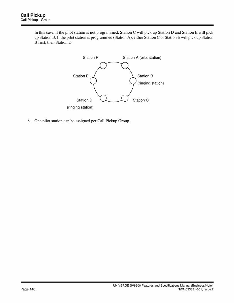
UNIVERGE SV8300 Features and Specifications Manual (Business/Hotel)Page 140 NWA-033631-001, Issue 2
Call PickupCall Pickup - Group
In this case, if the pilot station is not programmed, Station C will pick up Station D and Station E will pickup Station B. If the pilot station is programmed (Station A), either Station C or Station E will pick up StationB first, then Station D.
8. One pilot station can be assigned per Call Pickup Group.
Station A (pilot station)
Station B
(ringing station)
Station C
Station F
Station E
Station D
(ringing station)

UNIVERGE SV8300 Features and Specifications Manual (Business/Hotel)NWA-033631-001, Issue 2 Page 141
Call PickupCall Pickup - Designated Group
Call Pickup - Designated Group
General Description
This method permits a station user to answer an incoming call directed to another group by dialing the Call Pick-up - Designated Group feature access code and any station within the group to which the ringing station belongs.
Station Application
All stations.
Operating Procedure
Ringing telephone in another Call Pickup Group
1. Go off hook on an extension line and receive internal dial tone.
2. Dial Call Pickup - Designated Group feature access code.
3. Dial any station number within the Call Pickup Group to which the ringing station belongs.
4. Converse.
Service Conditions
1. All ringing calls directed to an extension in a Call Pickup Group can be picked up by this feature, exceptfor Trunk Queuing - Outgoing and Call Back.
2. This feature cannot be activated from feature dial tone.
3. A fully restricted station cannot pickup an incoming C.O. call.
4. If more than one station within the group is ringing, the system will connect the calls in the order in whichthe system data for the group is stored.

UNIVERGE SV8300 Features and Specifications Manual (Business/Hotel)Page 142 NWA-033631-001, Issue 2
Call Redirect
Call Redirect
General Description
Without answering incoming calls or held calls that terminate to the line keys of a Multiline Terminal, the callscan be transferred to a programmed station or Voice Mail System. Two transferring destination numbers can bedesignated per tenant, in system data programming. This feature can be used together with the Caller ID Displayfeature.
Station Application
All Multiline Terminals.
Operating Procedure
When Caller ID Display feature is provided to the Multiline Terminal
1. Confirm the calling party’s information by the operation of Caller ID Display.
Note: For the operating procedure of Caller ID Display, refer to the pages of Caller ID Display.
2. While in the CID (Caller ID Display) mode (while the CID key lamp lights), press the CRD (Call Redirect)key assigned to one of the programmable key on the Multiline Terminal.The call is transferred to the pre-assigned destination station and the CID key lamp goes out.
When Caller ID Display feature is not provided to the Multiline Terminal
1. Press the CRD key. The Multiline Terminal comes into CRD (Call Redirect) mode for six seconds, theCRD key lamp lights.
2. While in the CRD mode (while the CRD key lamp lights), press the line key of the incoming/held call.The call is transferred to the pre-assigned destination station and the CID key lamp goes out.
Service Conditions
1. A maximum of 8 Multiline Terminals can operate the Call Redirect simultaneously per system, includingthe terminal that is on Caller ID Display (CID) mode.If the CRD key is pressed on the 9th Multiline Terminal, CRD key lamp lights in a moment (0.5 seconds),then the call is transferred to the destination station.
2. CRD mode is continued for 6 seconds after the CRD key is pressed. After 6 seconds, the CRD key lampgoes out automatically and CRD mode is cancelled.
3. Two transfer destinations can be designated per tenant by system data programming. However, one of thesemust be a station, and the another must be a voice mail station.
4. If the call cannot be transferred to the destination station due to the busy or restriction of the destination,CID and CRD mode is cancelled.
5. When the following terminating system is assigned to the trunk, the call that is terminated to the trunk ac-cess key can be transferred by the CRD key.
• Trunk-Direct Appearances

UNIVERGE SV8300 Features and Specifications Manual (Business/Hotel)NWA-033631-001, Issue 2 Page 143
Call Redirect
• Trunk-Direct Appearances+TAS
6. On the following conditions, the call cannot be transferred by the CRD key because the destination is re-garded as busy state.
• When the call is a Camp-On call, and the destination is a UCD queue.
• When the call is held on an extension line/trunk access key, and the destination is a UCD queue.
• When the call is terminating to or held on a trunk access key, and the destination is setting Call For-warding-All Calls-Outside/Busy Line-Outside.
7. A call that is set Exclusive Hold by the other station cannot be transferred by the CRD key.
8. A voice call and a call from an Attendant Console cannot be transferred by the CRD key.
9. The system regards the Call Redirect operation as a Call Forwarding-No Answer. Information of the CRDsetting station is sent to the destination station.
UNIVERGE SV8300 Features and Specifications Manual (Business/Hotel)Page 144 NWA-033631-001, Issue 2
Call TransferCall Transfer - All Calls
Call Transfer
General Description
This feature permits a station user to transfer a call to another station in the system directly, or with assistancefrom the attendant.
Call Transfer - All Calls
General Description
This feature permits a station user to transfer incoming or outgoing calls to another station within the systemwithout attendant assistance.
Station Application
All stations.
Operating Procedure
To transfer a call in progress from a Single Line Telephone
1. Press the FLASH key (or momentarily press the hookswitch) and receive feature dial tone.
2. Dial the third party and receive ringback tone.
3. Restore the handset before the third party answers. The first and third parties will be connected when thethird party answers.
OR
Wait for the third party to answer and announce the transfer while keeping the first party on ConsultationHold. When the station user hangs up, the first and third parties are connected automatically.
To transfer a call in progress from a Multiline Terminal
1. Press the Transfer key and receive feature dial tone.
2. Dial the third party and receive ringback tone.
3. Restore the handset before the third party answers. The first and third parties will be connected when thethird party answers.
OR
Wait for the third party to answer and announce the transfer while keeping the first party on ConsultationHold. When the station user hangs up, the first and third parties are connected automatically.
Service Conditions
1. The station performing the Call Transfer can abandon the connection before the called party answers. If thecalled station does not answer within the predetermined time, a recall is initiated to the transferring station.
UNIVERGE SV8300 Features and Specifications Manual (Business/Hotel)NWA-033631-001, Issue 2 Page 145
Call TransferCall Transfer - All Calls
2. Outgoing calls may be transferred immediately.
3. A three-party Conference can be accessed from the Call Transfer state. The three parties connected can beas follows:
• three stations
• two stations and one trunk
• one station and two trunks.
4. A four-party Conference can be accessed from the Call Transfer state by Multiline Terminals only. Whenthe Consultation Hold of a three-party Conference connection is followed by calling another internal sta-tion, a four-way connection can be initiated. Refer to the Conference (Three/Four party) Features and Spec-ifications for additional information.
5. The maximum number of simultaneous Conferences per system is 16.
UNIVERGE SV8300 Features and Specifications Manual (Business/Hotel)Page 146 NWA-033631-001, Issue 2
October, 2008
Call TransferCall Transfer - Attendant
Call Transfer - Attendant
General Description
This feature permits a station user, while connected to an internal or outside call, to signal the Attendant andhave the Attendant transfer the call to another station within the system or to an outside connection.
Station Application
All stations.
Operating Procedure
Calling the Attendant
1. While engaged in a call, press the FLASH key on a Single Line Telephone or the Transfer key on a DigitalMultiline Terminal and receive feature dial tone.
2. Dial the operator access code (normally “0”). The Attendant Console RCL lamp flashes and ringing isheard. The station receives ringback tone.
3. After the Attendant answers, request the transfer and restore the handset.
Service Conditions
1. This feature is available for incoming and outgoing C.O. calls and station-to-station calls.
2. When the Attendant Console is in Night Service, the transferring station will receive reorder tone. Refer toAttendant Night Transfer Features and Specifications for more information.
3. The Call Transfer-Attendant feature allows a station user, while participating in a two-party connection, tocall the Attendant so that the Attendant may transfer the call or provide other assistance as required. A two-party connection can be comprised of two stations, or a station and a trunk
4. The Call Transfer - Attendant feature can be used by a fully restricted station. The Attendant can transfera fully restricted station to another station only.
5. Any station, including house phones without a dial, can transfer a call to the Attendant. Some additionalsystem programming may be necessary.

UNIVERGE SV8300 Features and Specifications Manual (Business/Hotel)NWA-033631-001, Issue 2 Page 147
Caller IDCaller ID Class
Caller ID
Caller ID Class
General Description
This feature receives the calling subscriber’s name and number sent from a public network using a MODEMsignal. It displays the name or number on an LCD of a Multiline Terminal or an Attendant Console.
Station Application
All Multiline Terminals with an LCD and Attendant Consoles.
Operating Procedure
To display the calling subscriber’s name or number when receiving/answering a call
No manual operation is required.
In case of receiving both the name and the number, system programming can specify which one has priority fordisplay.
To change the name/number display
Every time the Name/Number Display Change key is pushed on the Multiline Terminal or the Attendant Con-sole, the name and number are shown alternately.
To store the subscriber’s number for Save & Repeat feature
During a call, push the S&R (Save & Repeat) 0/1/2 key.
The S&R lamp lights if the number has been stored.In the case that no number has been sent from the public network, the S&R lamp will go off because the numberhas not been stored.
To redial by Save & Repeat feature
Push the S&R 0/1/2 key after hearing the Dial Tone.
Service Conditions
1. Up to 16 digits of the calling subscriber’s name or number can be displayed on the LCD of a Multiline Ter-minal or an Attendant Console.
2. Up to 16 or 24 digits of the calling subscriber’s number can be recorded on the SMDR.
3. Up to 24 digits of the calling subscriber’s number can be sent to the OAI computer.
4. The COT blade are required for receiving the Caller ID signals.
5. In case of receiving a subscriber’s name that differs from the name assigned by system programming, sys-tem programming can specify which name has priority.
6. The kind of the ringing tone can be assigned to each calling subscriber’s number respectively.

UNIVERGE SV8300 Features and Specifications Manual (Business/Hotel)Page 148 NWA-033631-001, Issue 2
Caller IDCaller ID Class
7. The destination station in the Day Mode/Night Mode can be specified for each calling subscriber’s number.
8. The priority for queuing (when the destination station belongs to an UCD group and all the stations arebusy) can be set by each calling subscriber’s number.
9. It can be specified whether Call Waiting will be set or not by each calling subscriber’s number.
10. When the system is in Mode “A” or “B”, Caller ID follows Night termination of Caller ID DevelopmentData Assignment.
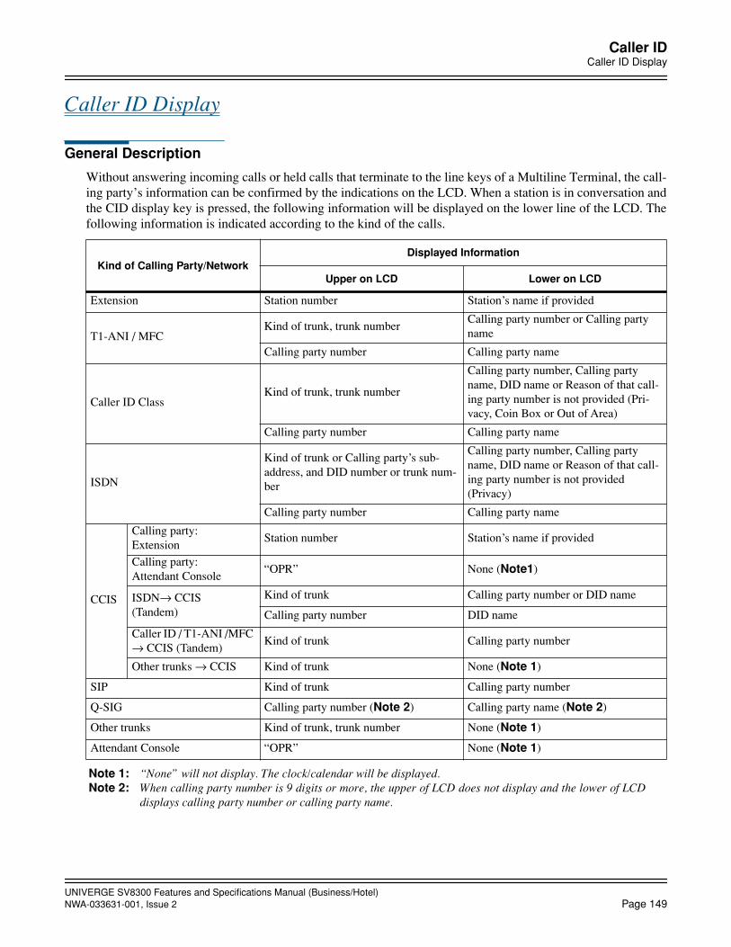
UNIVERGE SV8300 Features and Specifications Manual (Business/Hotel)NWA-033631-001, Issue 2 Page 149
Caller IDCaller ID Display
Caller ID Display
General Description
Without answering incoming calls or held calls that terminate to the line keys of a Multiline Terminal, the call-ing party’s information can be confirmed by the indications on the LCD. When a station is in conversation andthe CID display key is pressed, the following information will be displayed on the lower line of the LCD. Thefollowing information is indicated according to the kind of the calls.
Note 1: “None” will not display. The clock/calendar will be displayed.Note 2: When calling party number is 9 digits or more, the upper of LCD does not display and the lower of LCD
displays calling party number or calling party name.
Kind of Calling Party/NetworkDisplayed Information
Upper on LCD Lower on LCD
Extension Station number Station’s name if provided
T1-ANI / MFCKind of trunk, trunk number
Calling party number or Calling party name
Calling party number Calling party name
Caller ID ClassKind of trunk, trunk number
Calling party number, Calling party name, DID name or Reason of that call-ing party number is not provided (Pri-vacy, Coin Box or Out of Area)
Calling party number Calling party name
ISDN
Kind of trunk or Calling party’s sub-address, and DID number or trunk num-ber
Calling party number, Calling party name, DID name or Reason of that call-ing party number is not provided(Privacy)
Calling party number Calling party name
CCIS
Calling party: Extension
Station number Station’s name if provided
Calling party: Attendant Console
“OPR” None (Note1)
ISDN→ CCIS (Tandem)
Kind of trunk Calling party number or DID name
Calling party number DID name
Caller ID / T1-ANI /MFC → CCIS (Tandem)
Kind of trunk Calling party number
Other trunks → CCIS Kind of trunk None (Note 1)
SIP Kind of trunk Calling party number
Q-SIG Calling party number (Note 2) Calling party name (Note 2)
Other trunks Kind of trunk, trunk number None (Note 1)
Attendant Console “OPR” None (Note 1)

UNIVERGE SV8300 Features and Specifications Manual (Business/Hotel)Page 150 NWA-033631-001, Issue 2
Caller IDCaller ID Display
Station Application
All Multiline Terminals with LCD.
Operating Procedure
1. Press a CID (Caller ID Display) key assigned to one of the programmable key on the Multiline Terminal.The Multiline Terminal stays in CID mode for six seconds, the CID key lamp lights, and the LCD displaysthe calling party’s information of the incoming/held call for six seconds.
2. If there are multiple incoming calls or held calls, press the desired line key while the CID key lamp lights. The LCD displays the calling party’s information of the incoming/held call for six seconds.If the line key that is pressed while CID mode has no incoming/held call, CID mode is cancelled.
3. When the CID key is pressed again in CID mode, the CID key lamp goes out and CID mode is cancelled.
4. When the CID key is pressed during conversation after the CID mode is cancelled, the LCD displays thecalling party’s information of the incoming/held call again.
Service Conditions
1. A maximum of 8 Multiline Terminals can come into CID mode simultaneously per system, including theterminal that is on Call Redirect operation.
2. CID mode is continued for 6 seconds after the CID key is pressed. After 6 seconds, the CID key lamp goesout automatically and CID mode is cancelled.
3. If there is no incoming/held call on the line key and there is no Camp-On call, the Multiline Terminal doesnot come into CID mode even if the CID key is pressed.
4. If there are multiple incoming/held calls, Camp-On calls, the following priority for displaying is applied.
a. Camp-On call information set to the call in progress on the Multiline Terminal.
b. Incoming/held call information in order of the line key number (lowest to highest number).
5. When a call is transferred by Consultation Hold, the display shows the following information.Before the transfer operation finishes; the LCD displays the information of the station that holds the call. After the transfer operation finishes; the LCD displays the information of the held station/trunk.
6. When a call is set Executive Hold, the call information cannot be displayed on the other Multiline Terminal.
7. The information of voice call cannot be displayed.
8. When the following terminating system is assigned to the trunk, the calling party information of the call thatis terminated to the trunk access key can be displayed by the CID key.
• Trunk-Direct Appearances
• Trunk-Direct Appearance + TAS
Service Conditions on Caller ID Display for duration of trunk calls
1. Caller information can be displayed continuously for duration of incoming trunk calls on Multiline Termi-nal, IP Multiline Terminal, Softphone and Attendant Console. The duration of display can be selected bysystem data programming on system basis (display for 6 seconds or continuously).
2. Even if the name of Call Forward setting station is assigned, the caller information is displayed instead ofthe name of forward setting station (that is not displayed). If no caller information is received, the name offorward setting station can be displayed.
UNIVERGE SV8300 Features and Specifications Manual (Business/Hotel)NWA-033631-001, Issue 2 Page 151
Caller IDCaller ID Display
Service Conditions on simultaneous display of calling party number and name
1. Both calling party number and name can be displayed simultaneously on the Multiline Terminal LCD. Thecaller ID display format can be selected by system data programming; either new display format (both num-ber and name is displayed) or old display format (either number or name is displayed).
2. When either calling party number or name is received, the old display format is applied even if the new dis-play format is assigned by system data programming.

UNIVERGE SV8300 Features and Specifications Manual (Business/Hotel)Page 152 NWA-033631-001, Issue 2
Caller IDCaller ID - Station
Caller ID - Station
General Description
This feature enables the system to connect Single Line Telephones with Caller ID display function.
The following information is indicated according to the kind of the calls.
Station Application
Single Line Telephones with Caller ID display function (with the Bellcore spec.)
Operating Procedure
No manual operation is required.
Service Conditions
1. Caller ID stations cannot be accommodated in remote UNIT.
2. The maximum of 16 calls is available at the same time. However, the number of calls set in System datahas priority over the maximum number of simultaneous calls.
3. If all senders are busy, calls will be in progress without displaying calling number and name.
4. When a caller uses a Multiline Terminal, station number of the seized line will be sent as the calling partynumber.
5. When a caller uses a Multiline Terminal, name display can select either of My line or of seized line, by sys-tem data programming.
Kind of Calling Party/Network Displayed Information
Extension / Virtual Extension Station number or station’s name if provided
PS Station number or station’s name if provided
ISDN Extension Station number
T1 - ANICalling subscriber’s number orCalling subscriber’s name(Refer to service conditions #12 for details)
Caller ID ClassCalling subscriber’s number orCalling subscriber’s name(Refer to service conditions #12 for details)
ISDNCalling subscriber’s number orCalling subscriber’s name(Refer to service conditions #12 for details)
CCIS
Calling subscriber’s number or Calling subscriber’s name (Refer to service conditions on CCIS Name Dis-play on Caller ID Station)
Other trunks None
Attendant Console None
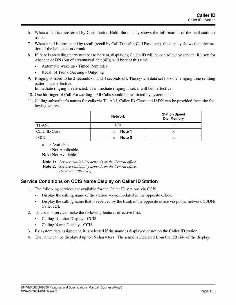
UNIVERGE SV8300 Features and Specifications Manual (Business/Hotel)NWA-033631-001, Issue 2 Page 153
Caller IDCaller ID - Station
6. When a call is transferred by Consultation Hold, the display shows the information of the held station /trunk.
7. When a call is terminated by recall (recall by Call Transfer, Call Park, etc.), the display shows the informa-tion of the held station / trunk.
8. If there is no calling party number to be sent, displaying Caller-ID will be controlled by sender. Reason forAbsence of DN (out of area/unavailable(4F)) will be sent this time.
• Automatic wake up / Timed Reminder
• Recall of Trunk Queuing - Outgoing
9. Ringing is fixed to be 2 seconds-on and 4 seconds-off. The system data set for other ringing tone sendingpatterns is ineffective. Immediate ringing is restricted. If immediate ringing is set, it will be ineffective.
10. One hit ringer of Call Forwarding - All Calls should be restricted by system data.
11. Calling subscriber’s names for calls via T1-ANI, Caller ID Class and ISDN can be provided from the fol-lowing sources:
Service Conditions on CCIS Name Display on Caller ID Station
1. The following services are available for the Caller ID stations via CCIS.
• Display the calling name of the station accommodated in the opposite office.
• Display the calling name that is received by the trunk in the opposite office via public network (ISDN/Caller ID).
2. To use this service, make the following features effective first.
• Calling Number Display - CCIS
• Calling Name Display - CCIS
3. By system data assignment, it is selected if the name is displayed or not on the Caller ID station.
4. The name can be displayed up to 16 characters. The name is indicated from the left side of the display.
NetworkStation SpeedDial Memory
T1-ANI N/A ×
Caller ID Class × Note 1 ×ISDN × Note 2 ×
× : Available– : Not ApplicableN/A: Not Available
Note 1: Service availability depends on the Central office.Note 2: Service availability depends on the Central office.
(NI-2 with PRI only)
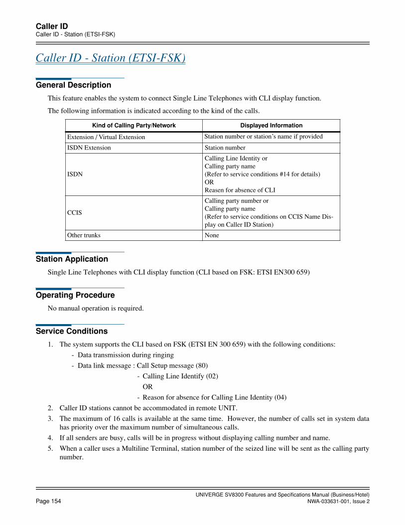
UNIVERGE SV8300 Features and Specifications Manual (Business/Hotel)Page 154 NWA-033631-001, Issue 2
Caller IDCaller ID - Station (ETSI-FSK)
Caller ID - Station (ETSI-FSK)
General Description
This feature enables the system to connect Single Line Telephones with CLI display function.
The following information is indicated according to the kind of the calls.
Station Application
Single Line Telephones with CLI display function (CLI based on FSK: ETSI EN300 659)
Operating Procedure
No manual operation is required.
Service Conditions
1. The system supports the CLI based on FSK (ETSI EN 300 659) with the following conditions:
- Data transmission during ringing
- Data link message : Call Setup message (80)
- Calling Line Identify (02)
OR
- Reason for absence for Calling Line Identity (04)
2. Caller ID stations cannot be accommodated in remote UNIT.
3. The maximum of 16 calls is available at the same time. However, the number of calls set in system datahas priority over the maximum number of simultaneous calls.
4. If all senders are busy, calls will be in progress without displaying calling number and name.
5. When a caller uses a Multiline Terminal, station number of the seized line will be sent as the calling partynumber.
Kind of Calling Party/Network Displayed Information
Extension / Virtual Extension Station number or station’s name if provided
ISDN Extension Station number
ISDN
Calling Line Identity orCalling party name(Refer to service conditions #14 for details)ORReasen for absence of CLI
CCIS
Calling party number or Calling party name (Refer to service conditions on CCIS Name Dis-play on Caller ID Station)
Other trunks None
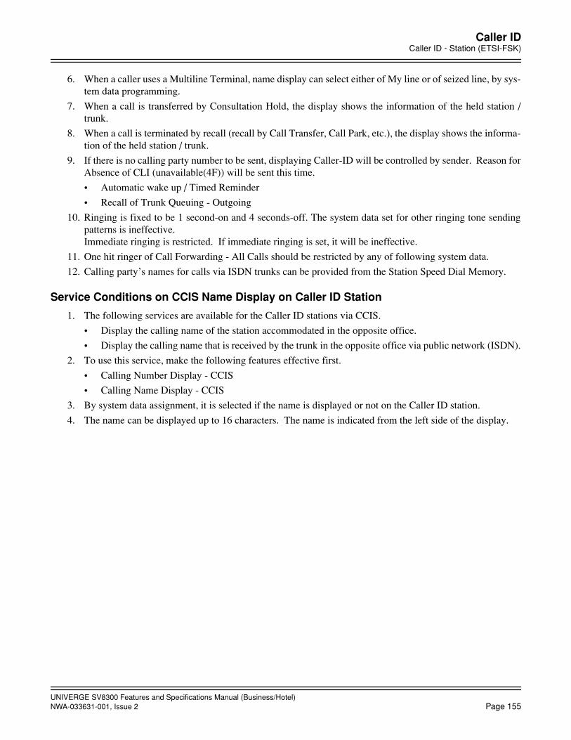
UNIVERGE SV8300 Features and Specifications Manual (Business/Hotel)NWA-033631-001, Issue 2 Page 155
Caller IDCaller ID - Station (ETSI-FSK)
6. When a caller uses a Multiline Terminal, name display can select either of My line or of seized line, by sys-tem data programming.
7. When a call is transferred by Consultation Hold, the display shows the information of the held station /trunk.
8. When a call is terminated by recall (recall by Call Transfer, Call Park, etc.), the display shows the informa-tion of the held station / trunk.
9. If there is no calling party number to be sent, displaying Caller-ID will be controlled by sender. Reason forAbsence of CLI (unavailable(4F)) will be sent this time.
• Automatic wake up / Timed Reminder
• Recall of Trunk Queuing - Outgoing
10. Ringing is fixed to be 1 second-on and 4 seconds-off. The system data set for other ringing tone sendingpatterns is ineffective. Immediate ringing is restricted. If immediate ringing is set, it will be ineffective.
11. One hit ringer of Call Forwarding - All Calls should be restricted by any of following system data.
12. Calling party’s names for calls via ISDN trunks can be provided from the Station Speed Dial Memory.
Service Conditions on CCIS Name Display on Caller ID Station
1. The following services are available for the Caller ID stations via CCIS.
• Display the calling name of the station accommodated in the opposite office.
• Display the calling name that is received by the trunk in the opposite office via public network (ISDN).
2. To use this service, make the following features effective first.
• Calling Number Display - CCIS
• Calling Name Display - CCIS
3. By system data assignment, it is selected if the name is displayed or not on the Caller ID station.
4. The name can be displayed up to 16 characters. The name is indicated from the left side of the display.
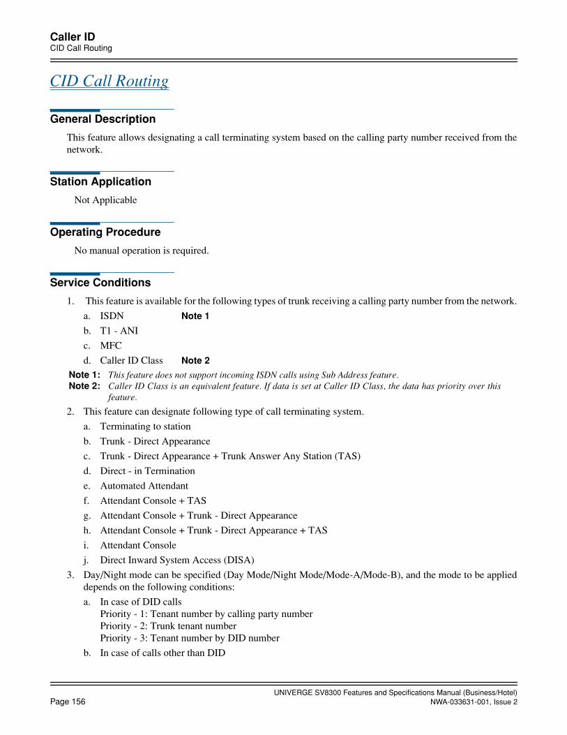
UNIVERGE SV8300 Features and Specifications Manual (Business/Hotel)Page 156 NWA-033631-001, Issue 2
Caller IDCID Call Routing
CID Call Routing
General Description
This feature allows designating a call terminating system based on the calling party number received from thenetwork.
Station Application
Not Applicable
Operating Procedure
No manual operation is required.
Service Conditions
1. This feature is available for the following types of trunk receiving a calling party number from the network.
a. ISDN Note 1
b. T1 - ANI
c. MFC
d. Caller ID Class Note 2
Note 1: This feature does not support incoming ISDN calls using Sub Address feature. Note 2: Caller ID Class is an equivalent feature. If data is set at Caller ID Class, the data has priority over this
feature.
2. This feature can designate following type of call terminating system.
a. Terminating to station
b. Trunk - Direct Appearance
c. Trunk - Direct Appearance + Trunk Answer Any Station (TAS)
d. Direct - in Termination
e. Automated Attendant
f. Attendant Console + TAS
g. Attendant Console + Trunk - Direct Appearance
h. Attendant Console + Trunk - Direct Appearance + TAS
i. Attendant Console
j. Direct Inward System Access (DISA)
3. Day/Night mode can be specified (Day Mode/Night Mode/Mode-A/Mode-B), and the mode to be applieddepends on the following conditions:
a. In case of DID callsPriority - 1: Tenant number by calling party numberPriority - 2: Trunk tenant numberPriority - 3: Tenant number by DID number
b. In case of calls other than DID
UNIVERGE SV8300 Features and Specifications Manual (Business/Hotel)NWA-033631-001, Issue 2 Page 157
Caller IDCID Call Routing
Priority - 1: Tenant number by calling party numberPriority - 2: Trunk tenant number
4. To determine the call terminating system from the calling party number, the received calling party numberis developed by the development pattern table. The calling party number is analyzed by the leading few digits. If the number matches the one specified bysystem data, the call will be terminated based on the system data assignment (not necessary to match alldigits of the number). If the number does not match, the call will be terminated based on the trunk numberor received DID number.
5. When the calling party number is not received, the call is terminated based on the trunk number or receivedDID number.
6. The development table for calling party number consists of 3,072 blocks.
As one digit - development requires one block, so that the max. number of developed numbers depends onthe number of digits to be developed.
7. Up to three development tables per system can be used for calling party number. This allows a calling partynumber development by DID number or trunk route number.
8. This feature is not effective for incoming trunk calls via CCIS.
9. When an incoming call is terminated to the Digital Multiline Terminal with LCD after changing the callterminating system based on the calling party number, the upper line of the LCD on the Digital MultilineTerminal will display as follows:
a. In case of DID calls : Trunk Type + Trunk Number, or Trunk Type + DID Number
b. In case of calls other than DID : Trunk Type + Trunk Number
10. Conditions interacting with Direct Inward Dialing (DID)
a. This feature shares the same Number Conversion Block memory with DID, so be sure to avoid double assignment of the system data.
b. This feature is effective only when Digit Conversion on DID calls is effective. If not effective, theDID call will terminate to the station.

UNIVERGE SV8300 Features and Specifications Manual (Business/Hotel)Page 158 NWA-033631-001, Issue 2
Caller IDNo CID Call Routing
No CID Call Routing
General Description
This feature allows designating a call terminating system based on the reason for absence of calling party num-ber received from the network.
Station Application
Not applicable
Service Conditions
1. This feature is available when the reason for absence of calling party number is received from the network.The applicable lines are the lines that can receive “reason for absence of calling party number” as follows.Other than following lines are not applicable for this feature.
• ISDN
• Caller ID Class
2. When an ISDN / Caller ID Class call with reason of absence of caller information is received, the call willnot be terminated to the called station and connected to the announcement requesting to send the callingparty number, or rejects the call termination, or forwards the call to the specified station. The call can berouted to one of the below options per tenant basis.
• Built-in Voice Response System
• A predetermined station
• Attendant Console
Incoming indication key can be specified for a call with no caller information. (DID only)
• A station based on the received called number with specified method
Following can be different between incoming call with caller information and without caller informa-tion, by system data programming.
- LED color on Multiline Terminal line key (DID, Ring down)
- Ring tone pattern of Multiline Terminal (DID only)
- Interval of ringing of Single Line Telephone, Multiline Terminal (DID only)
3. Depending on the reason for absence of caller information, the call termination can be selected by systemdata programming. (Designate the call routing only in the case of Reason=Privacy, or designate the callrouting of all calls with no caller information)
4. Conditions on ISDN calls
• When a call is incoming with called party subaddress, call routing of the call with reason for absenceof calling party number is not available (the call is terminated by called party subaddress). If the callednumber=unassigned number is received, this feature is also not available.
• When the reason for absence of calling party number is received in unrestricted digital incoming calls,the call cannot be restricted and terminated in normal manner, regardless of the system data whether acall with no calling party number is restricted.

UNIVERGE SV8300 Features and Specifications Manual (Business/Hotel)NWA-033631-001, Issue 2 Page 159
Caller IDNo CID Call Routing
5. Conditions on CCIS tandem calls
The reason for absence of caller information cannot be transmitted on CCIS tandem calls. Therefore, thedisplay of reason for absence of caller information and the call routing of the call with no caller informationare not available over CCIS.
UNIVERGE SV8300 Features and Specifications Manual (Business/Hotel)Page 160 NWA-033631-001, Issue 2
Camp-On/Call Waiting
Camp-On/Call Waiting
General Description
This feature provides selected stations or outside calls with Camp-On capability to a busy internal station. TwoCamp-On methods are provided. The call waiting method allows a station or an outside party to camp itself onto a busy station. The transfer method allows a transferred outside call to be camped-on to a busy station.
Station Application
All stations.
Operating Procedure
To set Camp-On (call waiting method)
From a Single Line Telephone
1. Dial the desired station number and receive busy tone.
2. Press the FLASH key (or momentarily press the hookswitch). Feature dial tone is received.
3. Dial the Camp-On (call waiting) feature access code and receive special ringback tone. Camp-On tone (4tone burst) is sent to the busy station.
From a Multiline Terminal
1. Dial the desired station number and receive busy tone.
2. Press the Transfer key. Feature dial tone is received.
3. Dial the Camp-On (call waiting) feature access code and receive special ring back tone. Camp-On tone (4tone burst) is sent to the busy station.
From an outside party on DID incoming call
1. Dial desired station number and receive busy tone.
2. Camp-On (call waiting) is automatically set if the Camp-On feature is allowed.
3. Receive ringback tone. Camp-On tone (3 tone burst) is sent to the busy station.
To set Camp-On with an outside call in progress (transfer method)
From a Single Line Telephone
1. Press the FLASH key (or momentarily press the hookswitch). The call in progress remains on ConsultationHold and feature dial tone is received.
2. Dial the desired station and receive busy tone.
3. Press the FLASH key (or momentarily press the hookswitch). Feature dial tone is received.
4. Dial the Camp-On (transfer) feature access code and receive service set tone. Camp-On tone (two tonebursts) is sent to the busy station.
5. Restore the handset.

UNIVERGE SV8300 Features and Specifications Manual (Business/Hotel)NWA-033631-001, Issue 2 Page 161
Camp-On/Call Waiting
From a Multiline Terminal
1. Press the Transfer key. The call in progress remains on Consultation Hold and feature dial tone is received.
2. Dial the desired station number and receive busy tone.
3. Press the Transfer key. Feature dial tone is received.
4. Dial the Camp-On (transfer) feature access code and receive service set tone. Camp-On tone (two tonebursts) is sent to the busy station.
5. Restore the handset.
To answer a Camp-On (transfer method or Call Waiting method) from any station
1. Receive Camp-On tone.
2. From a Single Line Telephone, momentarily press the hookswitch and dial the Call Hold feature accesscode. From a Multiline Terminal, press the FLASH key or Answer key. The existing call is placed on CallHold and the Camp-On call is automatically answered.
To answer a Camp-On (Call Waiting method-outside calls) from any station
1. Receive Camp-On (Call Waiting) tone.
2. From a Single Line Telephone, momentarily press the hookswitch. From a Multiline Terminal, press theFLASH key or Answer key. The existing call is placed on Call Hold and the Camp-On call is automaticallyanswered.
3. To alternate between two calls, press the FLASH key (or momentarily press the hookswitch) or Answerkey.
OR
1. Receive Camp-On (Call Waiting) tone.
2. Complete the existing call and restore the handset.
3. The Camp-On call is automatically terminated.
4. Lift the handset.
Service Conditions
1. Camp-On tone for call waiting method (internal calls) is four tone bursts. Camp-On tone for transfer meth-od is two tone bursts. Camp-On tone for the call waiting method (outside calls) is three tone bursts.
2. When Camp-On is activated to a station, any other Camp-On attempts to that station are denied and eitherreorder tone is provided (transfer method) or busy tone is provided (call waiting method). Once the Camp-On recalls to the originator or is answered (and the first call abandons, or the camped on party abandons),another Camp-On can be activated.
3. A Camp-On of an internal station will not recall. The station that sets camp-on must remain off-hook.
4. After a transfer Camp-On has remained Camped-On for a programmable period of time (8 to 128 seconds,30 seconds as set in default), the station that set the Camp-On will be recalled.
5. The ability to activate this feature can be allowed or denied in the Station's Class of Service.
6. A maximum of 28 stations can set call waiting Camp-On simultaneously. A maximum of 128 stations canset transfer Camp-On simultaneously.
7. A party camped-on for a transfer will hear Music On Hold (when provided) while on Consultation Hold.

UNIVERGE SV8300 Features and Specifications Manual (Business/Hotel)Page 162 NWA-033631-001, Issue 2
Camp-On/Call Waiting
8. Periodic Camp-On tone can be provided every 4 seconds. This can be allowed or denied in system pro-gramming on a per-system basis. When denied, a single Camp-On signal is received.
9. Camp-On can only be set if the called station is on a two-party call. Camp-On is denied if any of the fol-lowing apply to the busy station:
• dialing
• in Line Lockout
• receiving a system-generated tone
• protected against any override by DND key
• a Data Station in a Camped-On call
• activated with any of the following features:
• Attendant Override • Conference • Executive Override
• Attendant Camp-On • Consultation Hold • Privacy
• Call Hold (by key) • Data Line Security • Voice Call
• Call Transfer
10. When Camp-On is denied, the caller will receive reorder tone and can return to the original party (in thecase of a Camp-On transfer).
11. When single digit access codes are enabled, Multiline Terminal users can set a Camp-On without using theTransfer key twice.
12. Camp-On (call waiting) for outside calls (DID, CCIS incoming calls) can be allowed or denied on a per-trunk route basis or per-DID number basis.
13. When the called station is a pilot station in a Hunt group or UCD group, Hunting or UCD queuing is fol-lowed. If all stations in the Hunt group are busy, the called station is camped-on.
14. When the called station has set Call Forwarding-All Calls and the forwarding destination is busy, the for-warding destination is camped-on.
15. When the called station has set Call Forwarding-Busy Line and the forwarding destination is busy, the orig-inally called station is camped-on.

UNIVERGE SV8300 Features and Specifications Manual (Business/Hotel)NWA-033631-001, Issue 2 Page 163
Centrex Compatibility
Centrex Compatibility
General Description
A combination of features allows full integration of the SV8300 with Centrex service.
Station Application
All stations.
Operating Procedure
Refer to associated features.
Service Conditions
1. Flexible Configuration:
• Universal Ports to meet high Trunk-to-Station ratios.
• Building block approach for modular growth.
• Flexible Line Assignment.
• Wide variety of terminals.
2. Terminal Flexibility:
• Choice of terminals to meet multiple applications.
• Answering Positions:
16-line Multiline Terminal with Direct Station Selection/Busy Lamp Field Console (DSS/BLF)
OR
Attendant Console
• Standard Positions:
8-Line Multiline Terminal.
16-Line Multiline Terminal with LCD.
Single Line Telephones
3. High trunk-to-station ratio (256 trunks).
4. Ground/Loop Start Centrex line compatibility.
5. Centrex line Direct In Termination (DIT) to individual Single Line Telephones with secondary answeringat any Multiline Terminal.
6. Delayed Ringing for backup answering of Centrex incoming calls.
7. Hookflash to Centrex line from Multiline Terminal/Single Line Telephone.
8. Automatic seizure using dial access of individual Centrex lines with outgoing restriction control, up to 64trunks.
9. Code Restriction allows for inspection to follow the Centrex access code for Direct Outward Dialing.
10. Flexible extension numbering to match Centrex numbering pattern.
11. KF registration (FCC Part 68).

UNIVERGE SV8300 Features and Specifications Manual (Business/Hotel)Page 164 NWA-033631-001, Issue 2
Centrex Compatibility
12. Trunk Direct Appearance for Centrex lines.
13. Function keys at Multiline Terminals for easy access to Centrex features.
14. Automatic pause after Centrex access code.
15. Listed directory numbers display at Attendant Console.
16. Uniform Call Distribution (UCD) for quick and efficient handling of incoming calls.
17. Recall key provides timed hookflash to Centrex for feature access.
18. Prime line Assignment to Centrex line (when using direct trunk appearance). (Multiline Terminals only.)
UNIVERGE SV8300 Features and Specifications Manual (Business/Hotel)NWA-033631-001, Issue 2 Page 165
Check In/Check Out
Check In/Check Out
General Description
When this feature is activated, the following operations occur:
• Check In
Room Cutoff is cleared.
• Check Out
Room Status printout is supplied.
Do Not Disturb is reset.
Room Cutoff is set.
Message Waiting is reset.
Automatic Wake Up is cleared.
Station Application
Multiline Terminals with LCD assigned as Hotel/Motel Front Desk Instruments.
Operating Procedure
To activate Check In/Check Out for an individual guest room
1. Press the Check In/Check Out feature key.
2. Dial the desired station number.
3. Press the SET key to set Check In.
4. Press the RESET key to set Check Out.
Service Conditions
1. This feature can only be activated from the Hotel/Motel Front Desk Instrument or the PMS (Property Man-agement System). A line key on the Hotel/Motel Front Desk Instrument must be assigned as a Check In/Check Out function button. This feature can only be activated from the Hotel/Motel Front Desk Instrument.
2. This feature only applies to guest room stations.
3. Refer to the Hotel/Motel Front Desk Instrument and Property Management System Features and Specifica-tions for more information on Check In/Check Out.
Service Conditions on Built-in PMS on IP
1. When the Built-in PMS on IP is used, Check In/Check Out can be operated only from the PMS. The oper-ation is restricted from Hotel/Motel Front Desk Instrument.
2. When the Built-in PMS on IP is used, information regarding Check In/Check Out set/cancel from a PMSterminal can be automatically output to a printer connected to an CPU blade.

UNIVERGE SV8300 Features and Specifications Manual (Business/Hotel)Page 166 NWA-033631-001, Issue 2
Class of Service
Class of Service
General Description
This feature permits each station to be assigned a Class of Service in accordance with the degree of access de-sired. The Class of Service is used to assign restrictions for trunk access and feature access.
Station Application
All stations.
Operating Procedure
Normal operating procedures apply. Restrictions are automatically applied by the system based on the Class ofService assignments in system data for each station.
Service Conditions
1. Every extension is assigned as one of the following by Class of Service:
• House phone
• Hotline
• Automatic Intercom
• Dial Intercom
• Manual Intercom
• Multiline Terminal
• Single Line Telephone
2. A trunk route restriction class (from 1 to 8) is assigned for each station. This assignment is used to deter-mine whether a station is allowed or denied outgoing or incoming access to trunk routes. All eight routerestriction classes are assigned to allow or deny each trunk route. This allows the system to compare thestation assignment with the trunk route assignment and determine whether access is denied or allowed. Thedefault setting allows all stations access to all trunk routes.
3. The trunk restriction class is also used to provide flexibility in Code Restriction. Refer to the Code Restric-tion feature for details.
4. Sixteen combinations for each of three service classes (A, B, C) are available for assignment to stations.Based on the service feature class, the station is allowed or denied access to specific features. Each servicefeature class can be assigned to allow or deny each feature shown below.
• Service Class A
Call Forwarding - All CallsCall Forwarding - Busy LineCall Forwarding - No AnswerCall Forwarding - DestinationCall HoldTrunk Queuing - OutgoingCall Back

UNIVERGE SV8300 Features and Specifications Manual (Business/Hotel)NWA-033631-001, Issue 2 Page 167
Class of Service
Executive Override - OriginateExecutive Override - ReceiveSpeed Calling - SystemSpeed Calling - StationExternal PagingAutomatic Wake-up/Timed Reminder - selfAutomatic Wake-up/Timed Reminder - for othersCall Pickup Direct Camp-On (Transfer)Camp-On (Call Waiting) - Originate/ReceiveDo Not Disturb from Station/Return Schedule Message DisplayPriority Call Trunk to Trunk TransferMessage Wait- Set/ResetTimed QueueAccount Code EntryAuthorization Code/Forced Account CodeBackground Music (on Multiline Terminals)Voice Recording Card Access (Record/Reply/Delete)Announcement Service Replay (By Group Number)Split Call Forwarding - Busy LineCall Back - Multiple AssignmentMessage Reminder - OriginateMessage Reminder - ReceiveInternal Zone Paging Access
• Service Class B
Trunk Answer Any Station (TAS) ServiceIndividual Trunk Access from StationCustomer Administration Terminal (CAT) AccessDay/Night Mode Change by Station DialingPeriodic Time Indication ToneHotel/Motel Front Desk Instrument (Multiline Terminal)Privacy ReleaseDual HoldInhibit Override by DNDGroup ListeningVoice CallAnswer HoldMultiline Terminal Attendant Position
• Service Class C
Ringing Line PickupTone Ring Selection (on Multiline Terminal)Hookswitch Flash during internal callHookswitch Flash during outside (C.O.) callMultiline Terminal type (with or without LCD)Off-Hook Alarm overflow service (in case of busy terminating station)a. Automatic/Uniform Call Distribution queuing with Camp-On (Call Waiting)
b. Automatic/Uniform Call Distribution queuing

UNIVERGE SV8300 Features and Specifications Manual (Business/Hotel)Page 168 NWA-033631-001, Issue 2
Class of Service
c. Camp-On (Call Waiting)
d. Hunting
5. Separately from the above, each station can be assigned to have the following options:
6. Authorization Codes can be used to temporarily change the trunk route restriction class (incoming, outgo-ing, and code restrictions) and the feature service class (A, B, C) when a station is used. Refer to the Au-thorization Code feature.
7. Two assignments, one for day mode and one for night mode, are provided for trunk route restriction (in-coming, outgoing, and code restrictions) for each station. When the system is placed in night mode, thetrunk route restriction classes assigned for night mode are used for incoming and outgoing calls for all sta-tions.
8. Non-restricted stations can transfer outgoing calls after dialing to stations that are outgoing restricted.
9. Only the Attendant Console can permit restricted stations to place outgoing calls by the Attendant AssistedCalling feature.
10. If a restricted station is connected to an unrestricted station, the unrestricted station cannot add-on an outsideparty using a trunk route to which the restricted station is denied dial access. Attempts to do so result inimmediate ringback to the station attempting the add-on. The outside call must be made first before at-tempting to add-on the restricted station.
Feature Option
Do Not Disturb - Group Provided/Not Provided
Room Cut Off - Group Provided/Not Provided
Message Waiting Service Provided/Not Provided
Howler Tone Provided/Not Provided
Station Message Detail Recording Provided/Not Provided
Data Line Security Provided/Not Provided
Feature Option
Ringing to a Single Line Telephone when the exten-sion also appears on a Multiline Terminal
Provided/Not Provided
Secretary Station Secretary Station/Ordinary (Boss Station)
Automatic Message Waiting Cancel upon answering call (from Message Waiting-Set Station)
Automatic Cancel/No Automatic Cancel
Station Hunting for Non-DIT Calls Provided/Not Provided
Station Hunting for DIT calls Provided/Not Provided
VIP Class Provided/Not Provided
FAX Station FAX Station/Ordinary Station
UNIVERGE SV8300 Features and Specifications Manual (Business/Hotel)NWA-033631-001, Issue 2 Page 169
Code Restriction
Code Restriction
General Description
This feature allows the system to be programmed to restrict outgoing calls according to specific area and/or C.O.codes. This restriction is controlled on the basis of a three digit area code or six digit area and office code num-bering plan.
Station Application
All stations.
Operating Procedure
No manual operation is required.
Service Conditions
1. The programmed restriction pattern may consist of either those codes to be allowed, or those codes that areto be denied.
2. The Code Restriction feature is assigned on a per-station basis in Class of Service.
3. The system may be programmed to ignore the digit “1” before an area code so that true 3/6 restriction canbe applied.
4. Trunk Queuing - Outgoing provides queuing on selected outgoing trunk groups that are busy when dialed.The station user goes on-hook and is called back when an idle trunk is available. After answering the ring-back, the station-user dials the C.O. number. The number dialed must be allowed to the toll-restricted sta-tion user's line; otherwise, the trunk is immediately released and reorder tone is returned to the station user.
5. On a system wide basis, System Speed Dialing can be allowed to override or not override code restriction.The default is not to override code restriction.
6. Direct trunk line appearances on Multiline Terminals can be code restricted.
7. Code restriction is implemented as follows:
a. The system determines the need for code restriction by checking the assignment of code restriction (Yes or No) and the assignment of a digit code table for the selected trunk route.
b. The system compares the digits dialed with the digit code table assigned to the trunk route. If amatch is found, the system is provided with an assigned code restriction class. If no match is found,the call is allowed to progress normally.
c. An intersection table is provided in system programming that relates the station's restriction class tothe code restriction classes. There are 16 code restriction classes and 5 route restriction classes thatcan be used for code restriction deny/allow assignment. Once a code restriction class is obtainedfrom the digit code table, the intersection table is used by the system to decide whether the call isallowed or denied.
8. When a toll call is denied, Reorder Tone will be returned to the calling party (Toll Denial). If desired, thecalling party can be routed to the Attendant Console ICPT key (Toll Diversion). Either toll denial or tolldiversion is set on a per-system basis.
UNIVERGE SV8300 Features and Specifications Manual (Business/Hotel)Page 170 NWA-033631-001, Issue 2
Code Restriction
9. Six-digit code restriction is assigned by using Least Cost Routing (LCR) pattern tables. The system is pro-grammed to check the 50 office code tables to allow or deny assignment based on the office code after thearea code is matched by the system.
UNIVERGE SV8300 Features and Specifications Manual (Business/Hotel)NWA-033631-001, Issue 2 Page 171
Conference (Three/Four Party)
Conference (Three/Four Party)
General Description
This feature provides a station user the ability to add-on another party (trunk or station) to a call already inprogress. Single Line Telephone users can add up to one additional party and Multiline Terminal users can addup to two additional parties.
Station Application
All stations.
Operating Procedure
To add a third party
From a Single Line Telephone with a call in progress
1. Press the FLASH key (or momentarily press hookswitch). First party is placed on hold and feature dialtone is received.
2. Dial the second party (either another station number or a trunk access code plus the outside number).
3. Wait for the second party to answer.
4. Press the FLASH key (or momentarily press the hookswitch). A three-party Conference is established.
From a Multiline Terminal with a call in progress
1. Press the Transfer key. First party is placed on hold and feature dial tone is received.
2. Dial the second party (either another station or a trunk access code plus the outside number).
3. Wait for the second party to answer.
4. Press the Conf key. A three-party Conference is established. The display shows CONF plus the name andnumber of the trunks or station (if assigned).
From a Multiline Terminal with a call in progress when the third party is already placed on hold
1. Press the Conf key. The lamp on the Conf key is flashing.
2. Press the LINE/TRK key which the third party is placed on hold.
A three-way conference is established. The lamp on the Conf key is lit steadily. The display shows CONFplus the name and number of the trunks or stations (if assigned).
To add a fourth party with three party Conference in progress
1. Press the Transfer key. The two parties are placed on hold and feature dial tone is received.
2. Dial the third party (another station).
3. Wait for the third party to answer.
4. Press the Conf key. A four-party Conference is established. CONF is shown in the LCD.

UNIVERGE SV8300 Features and Specifications Manual (Business/Hotel)Page 172 NWA-033631-001, Issue 2
Conference (Three/Four Party)
Service Conditions
1. A maximum of two trunks can be used in a Conference.
2. Single Line Telephones can add up to one additional party (three-party Conference).
3. Multiline Terminals can add up to two additional parties (four-party Conference).
4. A Single Line Telephone will disconnect the last party added to a Conference [after the Conference (1 sta-tion, 2 trunk) is established] by providing a hookflash. This allows breaking up the Conference and return-ing to a two-party connection with the first party.
5. Multiline Terminals may allow other Multiline Terminals with the same line button appearance to enter theconversation (and therefore establish a Conference) by using the Privacy feature. Refer to the Privacy Fea-tures and Specifications for more information.
6. Once the second party answers, and prior to pressing the Conf key, Multiline Terminals may use the Trans-fer or Answer key to alternate between the two parties. Refer to the Broker's Call Features and Specifica-tions for more information.
7. During a three-party Conference, use of the Answer key on the Multiline Terminal will split the Conferenceinto a Broker's Call.
8. A maximum of 16 simultaneous Conferences can be established in the system.
9. The Hold key on Multiline Terminals can be used during a Conference to place the other parties on Hold(Exclusive or Nonexclusive). The other parties can continue to converse.
10. Retrieval of the first party on Multiline Terminals (after pressing the Transfer key dialing another partyand receiving ringback with no answer or busy tone) is accomplished by pressing the Transfer key. Useof the Recall key instead will provide feature dial tone and allows calling another party.
11. Attendant Override and Executive Override cannot be used on stations currently in a four-party Conference.
12. When attempting to call a second internal party after a hookflash, and the Single Line Telephone user en-counters internal busy tone or internal ringback with no answer, the user can return to the first party byhookflashing again.
13. When a call is made to a second external party after a hookflash, the next hookflash will result in a Confer-ence. By hookflashing again, the last connection is released, returning the Single Line Telephone user tothe original party.
14. Call Back and Message Waiting can be set to stations involved in a three- or four-party Conference.
15. Amplification is not provided for Conferences.
16. When a Single Line Telephone or Multiline Terminal user goes on-hook during a three-party Conferencewith two outside parties, a tandem connection will be established if one of the trunks provides a release sig-nal. If neither trunk provides a release signal, the trunks will be dropped. It is not possible to enter thistandem connection again.
17. When a Multiline Terminal user presses the Conf key prior to going on-hook during a three-party Confer-ence with two outside parties, a tandem connection will be established (Hold indication is provided). Pressthe held line button to enter into this tandem connection again.
18. An internal party must be off-hook using the handset (or in speakerphone mode) to be included in a Con-ference.
19. A Multiline Terminal station that sets three/four party conference is allowed to send DTMF to the other twoparties while engaging in the conference.DTMF is sent during the keypad is being pressed. If a keypad is pressed for less than 64msec, DTMF is sentfor 64 msec to 80 msec.
UNIVERGE SV8300 Features and Specifications Manual (Business/Hotel)NWA-033631-001, Issue 2 Page 173
Conference (Three/Four Party)
Conditions when a Multiline Terminal with a call in progress adds the third party which is already placed on hold on another Line/Trunk key
1. The conference leader must be a Multiline Terminal.
2. Other than conference leader, Multiline Terminal, Single Line Telephone, PS and trunk can participate threeparty conference. These participants must be connected or held on Line/Trunk keys on the conferenceleader's Multiline Terminal. The call held by Call Park cannot participate three party conference.
3. This feature is assigned on a tenant basis by system programming. When the system data for this feature isnot assigned, pressing the held Line/Trunk key will release the call in progress and establish a connectionwith the held party.
4. This feature (operation) is effective for establishing a three party conference. A four party conference is notallowed. Pressing the Conf key is not effective during the three party conference.
5. Attendant Console cannot be a conference leader or participant.
6. This feature uses two Line/Trunk keys on the conference leader's Multiline Terminal for establishing aconference (one is used for the call in progress and another is used for the call on hold). The lamps on theboth Line/Trunk keys will light in green when the three party conference is established.
7. When a Multiline Terminal user (conference leader) presses the HOLD key during a three party conference,the other two parties will be on hold (Exclusive Hold). The lamps on both Line/Trunk keys will be flashingin green. During the two parties are on hold, the conference leader can retrieve one of the held parties bypressing the related Line/Trunk key. From this status, pressing the Conf key plus the rest of the held Line/Trunk key establishes the three party conference again.
8. During the three party conference, key operations except the Hold key by the conference leader is not avail-able. Therefore, following operations are not available during the conference.
- Privacy Release by Conf Key
- Four-party conference and call transfer using Transfer Key
- Return to two-party connection by Answer Key.
All key operations are not available by the conference participant other than conference leader.
9. When any of conference participants goes on-hook, two-way connection is established with rest of partici-pants. When the conference leader goes on-hook, and the other participants are outside parties, a tandemconnection is established. If the tandem connection is restricted, the recall is activated for the conferenceleader and the party originally talking to the conference leader before establishing the conference. The partyoriginally held on the Line/Trunk key before establishing the conference will be released.

UNIVERGE SV8300 Features and Specifications Manual (Business/Hotel)Page 174 NWA-033631-001, Issue 2
October, 2008
Conference (32 Party)Group Call
Conference (32 Party)
General Description
This feature permits a station user (PS, Multiline Terminal, Single Line Telephone), Attendant, or a trunk partyto establish a conference among as many as 32 parties (including the conference leader). Two Conference meth-ods are available: Group Call and Meet-Me Conference.
Group Call
General Description
This feature enables a station user (PS, Multiline Terminal, Single Line Telephone) within the system or a trunkparty to establish a conference among as many as 32 parties. It also enables a station user to page a maximumof 31 parties simultaneously, excluding the conference leader.
Group Call - Automatic Conference
This feature enables a station user to establish a conference among as many as 32 parties. From a stationor Attendant, a maximum of 31 stations/trunks can be paged simultaneously except the conference leader.The paged stations/trunks are assigned to the simultaneous paging groups as participants by the system databeforehand.
Operating Procedure
To page stations of a group
From PS/Multiline Terminal/Single Line Telephone
1. Press the L1 or L2 key or go off hook, and receive a dial tone.
2. Dial the access code for a desired paging group and receive ringback tone.
OR
From PS
1. Dial the access code for a desired paging group.
2. Press L1 or L2 key, and receive a ringback tone.If the paged parties are all busy, a busy tone is heard.
3. You can converse sequentially with the participants of the conference in order of their answering.
To answer the paging
1. When the conference/paging call terminates, the LCD shows CNF GROUPxx (xx shows conference/pag-ing group number).
2. Answer the ringing of paging from the conference/group call leader.
3. You can converse with the conference leader and other participants.

UNIVERGE SV8300 Features and Specifications Manual (Business/Hotel)NWA-033631-001, Issue 2 Page 175
October, 2008
Conference (32 Party)Group Call
Service Conditions
1. The SV8300 supports up to 32-party conference.
2. The following conference/paging groups can be configured:
• One, 32-party conference/paging group
• Two, 16-party conference/paging groups
• Four, 8-party conference/paging groups
3. A maximum of 31 stations is paged simultaneously except the conference/group call leader. When 32 sta-tions are assigned to one group except the leader, the first 31 stations are paged in order of registered numberon the system data.In case of the group includes the leader and the leader is registered in first 31 stations, the first 30 stationsare paged in order of registered number on system data.
4. When a conference/group call leader and participants/paged stations hold the call or press the FLASH key(or momentarily press the hookswitch), hold tone is not provided to the conference.
5. A display of the elapsed time when a Multiline Terminal with LCD re-enter the conference after pressingthe Hold key or Transfer key starts from 00:00:01.
6. Up to 16 groups can be assigned as the conference/paging group by system data.
7. A maximum of 31 stations/trunks can be assigned in one conference/paging group.
8. Single line telephones, Multiline Terminals, PSs, Virtual Lines, and trunks can be assigned as the memberof the conference/paging groups.
9. Group Call can be answered by Call Pickup.
10. During a group call, PCS Roaming of PS is available. In this case, a display on the PS is not provided.
11. When all stations within the paged group are busy, the conference/group call leader hears a busy tone.
12. Any Single Line Telephone, Multiline Terminal, PS, and trunks that can detect a release signal from thenetwork can be a conference/group call leader.
13. When a station within the paged group does not answer in a predetermined time assigned by system data,the paging will stop. When all stations within the paged group do not answer in a predetermined time as-signed by system data, the conference/group call leader hears busy tone.
14. Any notification that the paged stations answer the group call is not provided to the conference/group callleader.
15. When a trunk is a conference/group call leader, the trunk line must be received release signal from the net-work.
16. When trunks are included in the conference/paging group, these trunks must be received answer signals andrelease signals from the network.
17. Amplification is not provided for conference/group calling.

UNIVERGE SV8300 Features and Specifications Manual (Business/Hotel)Page 176 NWA-033631-001, Issue 2
October, 2008
Conference (32 Party)Meet-Me Conference
Meet-Me Conference
General Description
This feature enables station users (PS, Multiline Terminal, Single Line Telephone) within the system, or trunkparties to join a conference of as many as 32 parties by dialing a specific access code. The conference partici-pants are automatically connected to the conference trunk. Conference participants may call in at preset timeor may be directed to do so by a conference coordinator.
Operating Procedure
To join a conference
From PS/Multiline Terminal/Single Line Telephone
1. Press the L1 or L2 key or go off hook, and receive a dial tone.
2. Dial the access code for Meet-Me Conference, and station user is automatically connected to a built-in con-ference trunk.
OR
From PS
1. Dial the access code for Meet-Me Conference.
2. Press L1 or L2 key, and the PS user is automatically connected to a built-in conference trunk.
To lock a conference from a participant (station)
1. Press the FLASH key (or momentarily press the hook switch), and dial the access code for ConferenceLock.
OR
Press the function button for Conference Lock. The function button lights in red.
2. The conference is locked and additional participants are restricted.
To unlock a conference from a participant (station)
1. Press the FLASH key (or momentarily press the hook switch), and dial the access code for Conference Un-lock.
OR
Press the function button for Conference Unlock. The function button lamp goes out.
2. The conference is unlocked.
Service Conditions
1. The SV8300 supports up to 32-party conference.
2. The following conference/paging groups can be configured:
• One, 32-party conference/paging group
• Two, 16-party conference/paging groups
• Four, 8-party conference/paging groups
UNIVERGE SV8300 Features and Specifications Manual (Business/Hotel)NWA-033631-001, Issue 2 Page 177
October, 2008
Conference (32 Party)Meet-Me Conference
3. When a conference/group call leader and participants/paged stations hold the call or press the FLASH key(or momentarily press the hookswitch), hold tone is not provided to the conference.
4. A display of the elapsed time when a Multiline Terminal with LCD re-enter the conference after pressingthe Hold key or Transfer key starts from 00:00:01.
5. Single Line Telephones, Multiline Terminals, PSs, and trunks can join the conference. When trunk partiesare included in a conference, PAD adjustment is required. Trunk lines must receive release signals from thenetwork.
6. A conference participant cannot release other participants from the conference.
Conditions for Alert Tone at Participation in a Conference
1. When someone joins a conference, an alert tone is sounded notifying all of other participants that a newparticipant arrives. As an alert tone at the participation in a conference, one burst of tone (tone sending time:160 ms) is sent once.
2. An alert tone is sounded regardless of whether participants in a conference use a station or trunk.
3. It is possible to change by system data whether an alert tone is sounded or not at participation in a confer-ence. An alert tone is sounded in default.
4. When a participant answers the paging of Group Call conference, an alert tone is sounded. If, however, atrunk without any answer signal is paged and the call is answered, no alert tone is sounded.
5. During a Group Call conference, if someone joins the conference with Meet-Me method, an alert tone isalso sounded.
Conditions for Conference Lock
1. A participant can lock a conference to restrict additional participation. Even if a conference is locked onceduring a conference, the conference can be unlocked by unlock operation.
2. All station participants (Single Line telephone, PS and Multiline Terminal) in a conference can lock andunlock the conference. It is impossible to lock and unlock a conference from any trunk.
3. Only the terminals that lock a conference can unlock the conference.
4. Only a conference group in which the terminals that lock the conference take part is locked.
5. When a conference is locked or unlocked, an alert tone is sent to conference participants notifying them thatthe conference is locked or unlocked.
6. An alert tone when a conference is locked is one burst of tone (tone sending time: 992 ms).
7. An alert tone when a conference is unlocked is two bursts of tone (tone period: On (224 ms) → Off (224ms) → On (224 ms).
8. When a person who locks a conference is released, the conference is unlocked automatically. In this case,when the conference is unlocked, an alert tone is not sounded.
9. The same function button that is set to Multiline Terminal is used to lock or unlock a conference. The func-tion is switched between lock and unlock every time the button is pressed.
10. If the lock or unlock button is set to the flexible function button of Multiline Terminal, when a conferenceis locked, the lock/unlock button of the set station is lit in red. When the conference is unlocked, the lightgoes out.
11. Even for a Group Call conference, it is possible for someone to join the conference later with Meet-Memethod; however, the lock function for the Group Call conference is not supported.
12. If someone attempts to join the locked conference, reorder tone is heard and “Restrict” is displayed on theLCD of Multiline Terminal.
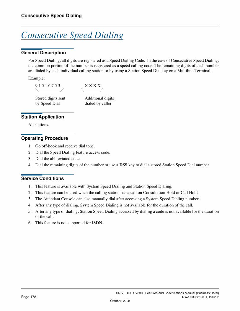
UNIVERGE SV8300 Features and Specifications Manual (Business/Hotel)Page 178 NWA-033631-001, Issue 2
October, 2008
Consecutive Speed Dialing
Consecutive Speed Dialing
General Description
For Speed Dialing, all digits are registered as a Speed Dialing Code. In the case of Consecutive Speed Dialing,the common portion of the number is registered as a speed calling code. The remaining digits of each numberare dialed by each individual calling station or by using a Station Speed Dial key on a Multiline Terminal.
Example:
9 1 5 1 6 7 5 3 X X X X
Stored digits sent Additional digitsby Speed Dial dialed by caller
Station Application
All stations.
Operating Procedure
1. Go off-hook and receive dial tone.
2. Dial the Speed Dialing feature access code.
3. Dial the abbreviated code.
4. Dial the remaining digits of the number or use a DSS key to dial a stored Station Speed Dial number.
Service Conditions
1. This feature is available with System Speed Dialing and Station Speed Dialing.
2. This feature can be used when the calling station has a call on Consultation Hold or Call Hold.
3. The Attendant Console can also manually dial after accessing a System Speed Dialing number.
4. After any type of dialing, System Speed Dialing is not available for the duration of the call.
5. After any type of dialing, Station Speed Dialing accessed by dialing a code is not available for the durationof the call.
6. This feature is not supported for ISDN.
UNIVERGE SV8300 Features and Specifications Manual (Business/Hotel)NWA-033631-001, Issue 2 Page 179
Consultation Hold
Consultation Hold
General Description
This feature permits a station user to hold any incoming or outgoing C.O. call, tie line call, or any calls withinthe office while originating a call to another station user within the system.
Station Application
All stations.
Operating Procedure
From a Multiline Terminal
To hold the original call and place a second call
1. Press the Transfer key and receive feature dial tone.
2. The original call is placed on hold and receives Music On Hold, if provided.
3. Dial an internal station number and receive ringback tone.
4. The second station answers. The original call is now on Consultation Hold.
To return to the original call
1. In any of the following cases, the calling station can return to the original call by pressing the Transfer key:
• If the second station called is busy.
• If the calling station cannot gain access to second station due to restriction or if the second station doesnot answer.
2. If the second station hangs up, the calling station will automatically be returned to the original call.
3. If the second station remains connected, pressing the Transfer key returns the original call to the MultilineTerminal while the second call enters Consultation Hold.
4. By pressing the Conf key, a three-party Conference will be initiated.
From a Single Line Telephone
To hold the original call and place a second call
1. Press the FLASH key (or momentarily press the hookswitch).
2. The original call is placed on hold and receives Music On Hold when provided.
3. Dial an internal station number and receive ringback tone.
4. The second station answers. The original call is now on Consultation Hold.
To return to the original call
1. In any of the following cases, the calling station can return to the original call by pressing the FLASH key(or momentarily pressing the hookswitch).
• If the second station called is busy.
• If the calling station cannot gain access to second station due to restriction.
UNIVERGE SV8300 Features and Specifications Manual (Business/Hotel)Page 180 NWA-033631-001, Issue 2
Consultation Hold
• If the second station does not answer.
2. If the second party hangs up, the calling station will automatically be returned to the original call.
3. If the originating station presses the FLASH key (or momentarily presses the hookswitch), a three-partyConference will be initiated.
Service Conditions
1. An outgoing exchange network or tie line call can also be made by the station user with a call on Consulta-tion Hold. Refer to Trunk-to-Trunk Connection and Conference Features and Specifications.
2. A station is only allowed to place one call on Consultation Hold at a time.
UNIVERGE SV8300 Features and Specifications Manual (Business/Hotel)NWA-033631-001, Issue 2 Page 181
Customer Administration Terminal (CAT)
Customer Administration Terminal (CAT)
General Description
In addition to the PC Programming, programming of the system can be done from selected Multiline Terminalswith LCD. The designated Multiline Terminals can be placed in program mode, and system data can then bechanged. To prevent unauthorized changes, password levels are assigned, providing authorization for access tocertain areas of programming and denying access to others.
Station Application
All Digital Multiline Terminals with LCD.
Operating Procedure
Refer to the Command Manual for programming instructions.
Service Conditions
1. Programming from a CAT can only be accomplished when the system is on-line.
2. The system must be initialized with default data before system data can be changed from the CAT.
3. All Multiline Terminals with LCD scanned during initialization will be CATs.
4. The commands System Data All Clear and System Data Partial Clear cannot be accessed from the CAT.The CAT cannot delete itself from the system program.
5. Only two CATs can be in program mode at the same time.
6. The data that can be changed from the CAT can be limited by the Password level assigned. There are eightlevels of Passwords that can be assigned in system programming. The relation between Password level andaccess to available commands is also assigned in system programming.
7. A password can consist of a maximum of any eight digits with the following limitation: The password can-not be CCCCCCCC or FFFFFFFF.
8. Caution should be exercised when assigning Passwords to command authorization levels. If a password isforgotten, access to system programming will be limited and a system initialization with subsequent pro-gramming may be required.
9. Refer also to the PCPro feature for information on Peg Count, Remove and Restore Service, and Fault Mes-sage.
10. When the CAT is off-line for programming, it cannot access normal terminal functions.

UNIVERGE SV8300 Features and Specifications Manual (Business/Hotel)Page 182 NWA-033631-001, Issue 2
Data Line Security
Data Line Security
General Description
This feature allows line circuits that are used for data transmission to be protected from interruptions such asAttendant Camp-On, Executive Override, and Attendant Override.
Station Application
Not applicable.
Operating Procedure
No manual operation is required.
Service Conditions
1. This feature is assigned in system programming on a per-station basis.
2. Data Line Security functions on all calls.
3. Data Line Security cannot prevent disruptions from interfering with data transmission when the disruptionoccurs outside the system.
4. The following connections are restricted when Data Line Security is allowed since transmitted tones are in-volved in their operation. All interrupt attempts directed towards stations with a Data Line Security call inprogress result in reorder tone:
• Attendant Camp-On
• Attendant Override
• Boss-Secretary Override
• Executive Override
• Camp-On
5. The ringing interval provided to a station assigned for Data Line Security is fixed at 1 second ON – 2 sec-onds OFF.

UNIVERGE SV8300 Features and Specifications Manual (Business/Hotel)NWA-033631-001, Issue 2 Page 183
Delayed Hotline
Delayed Hotline
General Description
When a station user goes off-hook and waits for a certain period of time without dialing operation, the stationuser is automatically routed to a specified Hotline station or an attendant. If the station user dials a number be-fore the preprogrammed time, the station user can make a call as usual.
Station Application
All stations.
Operating Procedure
To place a Delayed Hotline call
1. Lift the handset and wait for a certain period of time.
2. After the preprogrammed time (1 to 30 seconds, default: 10 seconds), a call is automatically originated tothe specified Hotline station or attendant.
To place a normal call
1. Lift the handset and dial the desired station number before the preprogrammed time.
Service Conditions
1. A Single Line Telephone, Multiline Terminal (My-Line/Sub-Line), IP Multiline Terminal, Soft Phone andPS can be a Delayed Hotline station.
2. Maximum of 100 stations can be assigned for Delayed Hotline stations (including normal Hotline stations).If bidirectional Hotline calling is required, two assignments (one for each direction) must be made. A max-imum of 50 pairs of bidirectional Hotlines can be assigned.
3. Even on a Delayed Hotline station, just one digit dialing after off-hook disables the Delayed Hotline call,even with the ORT time out, assuming the user’s intention to dial. Reorder tone is received.
4. This feature cannot be used together with the features that require System data setting, such as Intercom andHouse Phone.
5. Preset Dialing on Multiline TerminalDelayed Hotline station (Multiline Terminal) can use Preset Dialing.

UNIVERGE SV8300 Features and Specifications Manual (Business/Hotel)Page 184 NWA-033631-001, Issue 2
Delayed Ringing
Delayed Ringing
General Description
This feature enables trunks and station lines to ring immediately at the terminating station, but also, after a pro-grammable period of time has elapsed, to ring at secondary Multiline Terminals with that trunk or line appear-ance.
Station Application
All Multiline Terminals.
Operating Procedure
No manual operation is required.
Service Conditions
1. Delayed Ringing is assigned in system programming on a per line key basis.
2. The timing of call termination to the start of Delayed Ringing is programmable in system data in incrementsof 2 seconds to a maximum of 40 seconds (default value = 10 seconds).
3. When Delayed Ringing and Call Forwarding - No Answer are applied to the same call, the feature thattimes-out first will take priority.

UNIVERGE SV8300 Features and Specifications Manual (Business/Hotel)NWA-033631-001, Issue 2 Page 185
Diagnostics
Diagnostics
General Description
To assist maintenance personnel, the system provides diagnostic capabilities such as fault code generation, de-vice status information and alarm information recording that can be accessed from the PCPro or Customer Ad-ministration Terminal (CAT).
Station Application
Not applicable.
Operating Procedure
Refer to the Maintenance Manual for operating procedures.
Service Conditions
1. The following station status information can be displayed on the PCPro or CAT by direct command.
• Idle• Line Lockout• Dialing• Tone Trunk Connection (reorder tone, busy tone, service set tone, etc.)• Types of Connection, (station to station, three way calling, voice calling, holding, etc.)• Destination number (trunk number, register number)• Short circuit on line
2. The following trunk status information can be displayed on the PCPro or CAT by direct command:
• Idle• Ringing in• Incoming queue to Attendant Console• Holding• In a tandem connection• Incoming queue to UCD• Dialing• Receiving dialed digits
3. The following information is stored and can be displayed on the PCPro or CAT using a memory dump com-mand in hexadecimal format:
• Program address where an endless loop has occurred.• Last initialization time for the main program.• Last initialization time for the firmware program.• The reason for initialization (power-on, RESET key, endless loop, sense switch, command from PCPro
or CAT).
4. The system has a built-in patrol program that monitors the status of all connected devices. Additionally,when no response or an invalid response from a device is received, this program stores in memory the slotnumber of that device. From the PCPro or CAT a maintenance person can read the slot number of any de-vice that does not respond to the CPU or provides an illegal status to the CPU.

UNIVERGE SV8300 Features and Specifications Manual (Business/Hotel)Page 186 NWA-033631-001, Issue 2
Dial by Name
Dial by Name
General Description
This feature allows a Multiline Terminal user to search for a desired number by name. The number and nameare registered in the system and they are shown on Multiline Terminal LCD. The Multiline Terminal user cansearch for the desired number by name using up or down soft keys. When the Multiline Terminal user finds thedesired number, the call can be originated by pressing the Line/Trunk key or going off hook.
Station Application
Multiline Terminal with LCD and Soft Key.
Operating Procedure
To search a calling number by name and originate a call by System Speed Dialing
1. From the idle state, press the SYS soft key on the Multiline Terminal.
2. To search by name, enter up to the first four characters of a name using the keypad. (Refer to Service Con-dition #2.)
3. Press the UP or DOWN soft key to start the search.
4. The name and the number are shown on the LCD. If more than one name matches the letters entered, scrollthrough the matches with the UP or DOWN soft key. If no matches are founds, the first System Speed Dialbuffer will be displayed.
5. To search for a different name, repeat Step 2.
6. Manual search is formed by pressing the UP or DOWN soft key until the desired name or buffer number islocated.
7. In either case, going off hook, pressing the Speaker key, or selecting a Line/Trunk key will originate a callto the selected number.
To search a calling number by name and originate a call by Station Speed Dialing
1. From the idle state, press the STA soft key on the Multiline Terminal. For Dterm Series i, press the Direc-tory key.
2. To search by name, enter up to the first four characters of a name using the keypad. (Refer to Service Condition #2.)
3. Press the UP or DOWN soft key to start search.
4. The name and the number are shown on the LCD. If more than one name matches the letters entered, scrollthrough the matches with the UP or DOWN soft key. If no matches are founds, the first Station Speed Dialbuffer will be displayed.
5. To search for a different name, repeat Step 2.
6. Manual search is formed by pressing the UP or DOWN soft key until the desired name or buffer number islocated.
7. In either case going off hook, or pressing the Speaker key, or selecting a Line/Trunk key will originate acall.

UNIVERGE SV8300 Features and Specifications Manual (Business/Hotel)NWA-033631-001, Issue 2 Page 187
Dial by Name
To program a new telephone number with name for Station Speed Dialing
1. From the idle state, press the STA soft key on the Multiline Terminal. For Dterm Series i, press the Directorykey.
2. Press the ENTRY soft key to search the vacant memory block of Station Speed Dial. The LCD displays35: to indicate that no number/name is programmed.
3. Press the NAME soft key to enter a new name. Receive special dial tone, if assigned by system program-ming.
4. Enter the desired name (up to 16 characters) using the letters on Keys 2 through 9 (Refer to Service Condi-tions #2 for details on how to enter the characters.).
5. Press the NUMBER soft key to enter the number associated with the name. Receive special dial tone, ifassigned by system programming.
6. Dial the desired telephone number including the trunk access code (ex. 9).
7. Press the SET soft key. The LCD will display SET OK.
To change the stored name and/or number for Station Speed Dialing
1. Search the name and/or number to be changed followed by the operating procedure #1 through #4 of “Tosearch a calling number by name and originate a call for Station Speed Dialing.”
2. During the LCD displays the stored number with name to be changed, press the ENTRY soft key.
3. Press the NUMBER soft key to change the stored number only. Receive special dial tone, if assigned bysystem programming. Move to operating procedure #6 below to change the number.
OR
3. Press the NAME soft key to change the stored name only (or both the stored name and number). Receivespecial dial tone, if assigned by system programming.
4. Enter the desired name (up to 16 characters) using the letters on Keys 2 through 9 (Refer to Service Condi-tions #2 for details on how to enter the characters.). The old name is erased and the new name is displayed.
5. Press the SET soft key to end the operation, if changing the stored name only.
OR
5. Press the NUMBER soft key to proceed to change the stored number. Receive special dial tone, if assignedby system programming.
6. Dial the desired telephone number including trunk access code (up to 4 digit of trunk access code and up to26 digit of telephone number). The old number is erased and the new number is displayed.
7. Press the SET soft key. The LCD will display SET OK.
To erase Directory Entry
1. From an idle state, press the STA soft key on a Multiline Terminal.
2. Search by name: Enter up to four characters of a name using the keypad.
3. Press the UP or DOWN soft key to start search.
4. The name and the telephone number are shown on the LCD.
5. Press the ENTRY soft key.
6. Press the DELETE soft key. The name and the telephone number are deleted.
7. From this state, you can do below operation.
• Input mode change (Alphabet←→Number)

UNIVERGE SV8300 Features and Specifications Manual (Business/Hotel)Page 188 NWA-033631-001, Issue 2
Dial by Name
• Press the ENTRY soft key
• Press the UP or DOWN soft key
Character Deletion
(1) To delete character during directory search
1. From an idle state, press the STA or SYS soft key on a Multiline Terminal.
2. Search by name: Enter up to four characters of a name using the keypad.
3. If the input character is wrong, press the BK soft key. One character from the last input is deleted.
4. Reenter the correct character.
(2) To delete character during directory entry
1. From an idle state, press the STA soft key on a Multiline Terminal.
2. Press the ENTRY soft key to search the vacant memory block of Station Speed Dial.
3. Press the NAME soft key to enter a new name.Receive special dial tone, if assigned by system programming.
4. Enter the desired name (up to 16 characters) using the keypad.
5. If the input character is wrong, press the BK soft key.One character from the last input is deleted.
6. Reenter the correct character.
7. If the correct name is entered, press the NUMBER soft key to enter the telephone number associated withthe name. Receive special dial tone, if assigned by system programming.
8. Dial the desired telephone number including the trunk access code.
9. If the input number is wrong, press the BK soft key.One number from the last input is deleted.
10. Reenter the correct number.
11. If the correct number is entered, press the SET soft key.
The above character deletion operation is also available when changing the stored name and number.
Service Conditions
1. Service
a. Up to 32 Multiline Terminals are available to use this feature at the same time.
b. The Multiline Terminal returns to idle status after the 30 seconds from pressing SYS/STA/Directorykey and no key operation is activated.
c. If the speed dialing memory block is not assigned to the Multiline Terminal, the SYS/STA/Directorykey is not affected when the Multiline Terminal user presses these keys.
d. This service feature is ended or interrupted by pressing the Hold key.
e. When the Multiline Terminal uses this feature, the incoming call to My Line is rejected.
f. When the Multiline Terminal uses this feature, the incoming call to Sub Line key or trunk lineappearance can be terminated to the Multiline Terminal. In this case, the related line/trunk lamp is
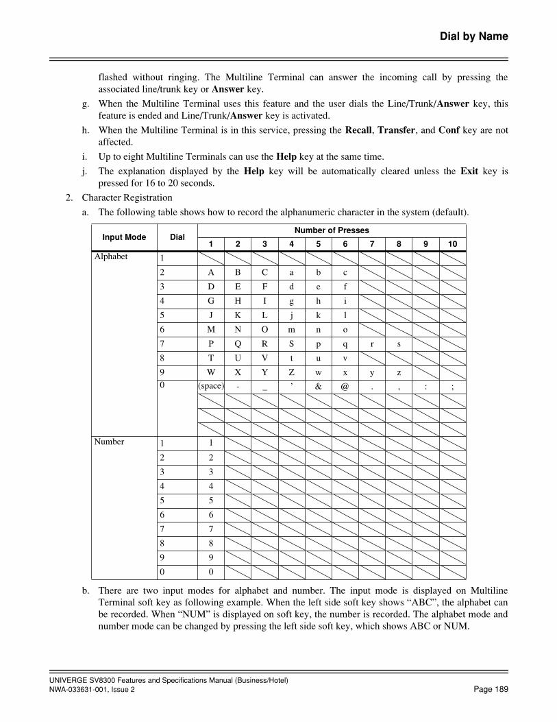
UNIVERGE SV8300 Features and Specifications Manual (Business/Hotel)NWA-033631-001, Issue 2 Page 189
Dial by Name
flashed without ringing. The Multiline Terminal can answer the incoming call by pressing theassociated line/trunk key or Answer key.
g. When the Multiline Terminal uses this feature and the user dials the Line/Trunk/Answer key, thisfeature is ended and Line/Trunk/Answer key is activated.
h. When the Multiline Terminal is in this service, pressing the Recall, Transfer, and Conf key are notaffected.
i. Up to eight Multiline Terminals can use the Help key at the same time.
j. The explanation displayed by the Help key will be automatically cleared unless the Exit key ispressed for 16 to 20 seconds.
2. Character Registration
a. The following table shows how to record the alphanumeric character in the system (default).
b. There are two input modes for alphabet and number. The input mode is displayed on MultilineTerminal soft key as following example. When the left side soft key shows “ABC”, the alphabet canbe recorded. When “NUM” is displayed on soft key, the number is recorded. The alphabet mode andnumber mode can be changed by pressing the left side soft key, which shows ABC or NUM.
Input Mode DialNumber of Presses
1 2 3 4 5 6 7 8 9 10
Alphabet 1
2 A B C a b c
3 D E F d e f
4 G H I g h i
5 J K L j k l
6 M N O m n o
7 P Q R S p q r s
8 T U V t u v
9 W X Y Z w x y z0 (space) - _ ’ & @ . , : ;
Number 1 1
2 2
3 3
4 4
5 5
6 6
7 7
8 8
9 9
0 0

UNIVERGE SV8300 Features and Specifications Manual (Business/Hotel)Page 190 NWA-033631-001, Issue 2
Dial by Name
c. In the alphabet mode, the input character is fixed by # key.
Example 1: Dial 222#22# → CB is recorded.
Example 2: Dial 222999# → CY is recorded.
Example 3: Dial 222#22 then press “ABC” soft key. → CB is recorded and input mode is changedfrom alphabet to number.
3. Number and Name Registration
a. In the alphabet and number input mode, when the Feature key is pressed, the Feature key lamp is flashed and Speaker key lamp is lit.
b. Up to 16 characters can be recorded as a name.
c. Up to four digits of trunk access code and up to 26 digits of station number can be recorded.
d. When the new name and number are recorded, the system automatically search the vacant memoryblock after pressing the ENTRY soft key.
e. In the name and number registration operation, if both name and number are not registered in speeddialing memory block, the Multiline Terminal LCD shows as follows.
f. Timeout for name entry after pressing the NAME soft key is fixed at 30 seconds.
g. Timeout for number entry after pressing the NUMBER soft key is fixed at 10 seconds.
h. Sending special dial tone after pressing the NAME or NUMBER soft key can be allowed or deniedby system data assignment.
4. Search
a. Up to four characters are used as a keyword when the number is searched by name.
b. If the Multiline Terminal user enters character exceeding four, it is invalid.
c. When the same name has been registered in the system, the LCD shows the name and number that areassigned the lowest memory block number.
d. When searching is performed without entering a keyword, the LCD shows the lowest memory blocknumber available for the Multiline Terminal.
e. When no keyword for searching has been registered, the LCD shows the lowest memory blocknumber available for the Multiline Terminal.
f. After searching, the Multiline Terminal user can search next speed dialing number by pressing UP orDOWN soft key.UP= displays the lower number than the block number displayed.DOWN= displays the higher number than the block number displayed.When the block number reaches the lowest/highest by pressing UP or DOWN soft key, one more
11:22 PM MON 12 MAR 1999
ABC UP DOWN
11:22 PM MON 12 MAR 1999
NUM UP DOWN
Alphabet Mode Number Mode
11:22 PM MON 12 MAR 1999ABC ENTRY UP DOWN
35:

UNIVERGE SV8300 Features and Specifications Manual (Business/Hotel)NWA-033631-001, Issue 2
Page 191
Dial by Name
pressing rounds to the highest/lowest memory block number.
g. When searching is performed, the first 24 digits are displayed if the number exceeds 24 digitsincluding memory block number.
h. When the system uses Station Speed Dialing memory Blocks 0, 1, 2, and 3 for System Speed Dialing,another “SYS” Soft Key should be assigned for each memory block basis.
• System Speed Dialing 300 memory : F5014 (standard)
• System Speed Dialing 1000 memory # (Block No. 0) : F5016
• System Speed Dialing 1000 memory # (Block No. 1) : F5017
• System Speed Dialing 1000 memory # (Block No. 2) : F5018
• System Speed Dialing 1000 memory # (Block No. 3) : F5019
When the System Speed Dialing memory is limited to use by system data, searching of the SystemSpeed Dialing 1000 memory should not be done. (Pressing SYS key is ineffective.)
5. Originating a Call
a. To originate calls after searching, press either TRK key, Line key (My Line/Sub Line) or
Speaker
key, or off hook.
b. When the user originates a call by pressing the TRK key, the registered trunk access code is ignored.When the user originates a call by pressing a Line key or
Speaker
key, or going off hook, trunkaccess code registered can be processed and the appropriate trunk is selected.
c. When the user originates a call after searching, the number is registered into the stack dial and Save& Repeat.
6. Name Indication
a. A name is displayed on Multiline Terminal when a call is originated by System Speed Dialing with the following operation.
• System Speed Dialing originated with Access code and Speed Dialing number.
• System Speed Dialing originated with off-hook, press System Speed Dialing button and Speed Di-aling number.
b. A name is displayed on Multiline Terminal when a call is originated by Station Dialing with thefollowing operation.
• Station Speed Dialing originated with Access code and Speed Dialing number.
• Station Speed Dialing originated with off-hook, press Station Speed Dialing button (F0064) andSpeed Dialing number.
• Station Speed Dialing originated with Station Speed Dialing button (F11XX).
• Station Speed Dialing originated with Redial key and Speed Dialing number.
c. A name is displayed on the Multiline Terminal when the Multiline Terminal user verifies theregistered Speed Dialing number with the following operation.
• Dial Speed Dialing Access code and Speed Dialing number.
• Press Station Speed Dialing button (F0065) and Speed Dialing number.
• Press Feature key, Station and Speed Dialing button (F11XX).
• Press Feature key, Recall Button, and dial Speed Dialing number.
d. A name is displayed when a Multiline Terminal user originates a call by Speed Dialing-One Touch.
e. A name is displayed when a Multiline Terminal user verifies the registered Speed Dialing numberwith Feature key and One Touch key.
UNIVERGE SV8300 Features and Specifications Manual (Business/Hotel)
Page 192
NWA-033631-001, Issue 2
Dial by Name
f. When outgoing call encountered all trunk busy status and Route Advance is activated, the name isdisplayed on Multiline Terminal LCD.
g. A name is displayed when a Multiline terminal user originates a call with Hot Line.
h. The Name Display/Guest Name are registered before the name in a station to station call made bySpeed Dialing-One Touch key.
i. A name is displayed for about 6 seconds on Multiline Terminal LCD when a Multiline Terminal useroriginates a call by System and Station Speed Dialing/One Touch key.
7. Erase Directory EntryA Multiline Terminal user can erase the directory data from the telephone set by pressing the DELETE softkey. This is effective for Station Speed Dialing-based directory data only. System Speed Dialing-based di-rectory data cannot be added, modified and erased from the telephone set.
8. Character Deletion During directory search or directory data entry, a Multiline Terminal user can delete the input characters ornumbers from the last input and re-enter the correct characters or numbers. By pressing the BK soft keyonce, one character or number can be deleted.

UNIVERGE SV8300 Features and Specifications Manual (Business/Hotel)NWA-033631-001, Issue 2
Page 193
Dial Conversion
Dial Conversion
General Description
The system can be assigned to use rotary Dial Pulse (DP) or Dual Tone Multifrequency (DTMF) trunks andstations. This feature provides for the repeating of digits dialed by the station user onto the C.O. trunks.
Station Application
All stations.
Operating Procedure
Normal call handling procedures apply.
Service Conditions
1. Trunks are assigned for DP and/or DTMF on a trunk route basis.
2. Single Line Telephone circuits are assigned for DP and/or DTMF through station Class of Service for thestation number assigned to the circuit. The Single Line Telephone circuits can accept 10 or 20 PPS.
3. The system will automatically provide Dial Conversion when the station is a DTMF Single Line Telephoneand dialing is being done on a DP trunk.
4. The system can be assigned to provide DTMF dialing on trunks for Attendant Consoles only, while gener-ating rotary dial pulses for station dialing.
5. For an outgoing call on a trunk once the outgoing register times out (6 seconds after the last digit is dialed),further digits dialed out by a Multiline Terminal will be DTMF. The duration of the tones will be the sameas the length of time the dial pad key is pressed. This feature allows Multiline Terminals to send DTMFsignals to external equipment such as computers and other dial up services.
6. The dial pulse make ratio is programmable for 33% or 39% (default is 39%). The dial pulse interdigit pausecan be set from 300 ms to 900 ms (in increments of 100 ms) or 1100 ms (default is 800 ms).
7. The DTMF signal width is programmable for 64 ms or 128 ms (default is 64 ms). The DTMF interdigitpause can be set for 32, 64, 80, 96, 160, 192, or 240 ms (default is 96 ms).
UNIVERGE SV8300 Features and Specifications Manual (Business/Hotel)
Page 194
NWA-033631-001, Issue 2October, 2008
Direct Data Entry
Direct Data Entry
General Description
This feature allows a maid or other hotel personnel to enter numeric data to the PMS (Property ManagementSystem), using the guest room station for entry through dial operation.
Station Application
All stations.
Operating Procedure
1. Lift the handset and receive dial tone.
2. Dial the Direct Data Entry access code and receive feature dial tone.
3. Dial input data to the PMS and receive service set tone.
4. Restore the handset.
Service Conditions
1. This feature is activated from a guest room telephone.
2. The digit 0, 1, 2, 3, 4, 5, 6, 7, 8, and 9 can be used for the input data.
3. The input data can be sent out to the PMS. The output option can be selected by system data programming.
4. A maximum of 30 digits can be entered in one operation to the PMS. If data exceeds 30 digits, the guestroom station receives reorder tone.
5. If the input data to be sent is less than 30 digits, “#” can be used to end the digit string. (The “#” is not sentto the PMS.)
Example: Access code + 1234567890#
6. Reorder tone will be received instead of service set tone if the PMS does not respond within 15 seconds orsends a negative answer to the system.

UNIVERGE SV8300 Features and Specifications Manual (Business/Hotel)NWA-033631-001, Issue 2
Page 195
Direct Digital Interface
Direct Digital Interface
General Description
This service feature provides the capability to connect trunks from the SV8300 directly to T1 carrier links usingeither a private or public network.
Operating Procedure
No manual operation is required.
Service Conditions
1. Each Office Hierarchy is defined as follows:
a. Source office
One center will operate as the Source Office. This location has two highly stabilized source oscillators,and distributes the Source Clock to all the systems through the Digital Interface lines.
b. Sub-Source office
This office operates using a Phase Lock Oscillator (PLO) to synchronize with the clock at the SourceOffice. If the Source Clock fails, the Sub-Source office can operate using its own backup oscillator.
c. Receiver office
This office is arranged so it will have at least two clock routes, one for Source and the other for standby.Synchronization Clock is derived from incoming PCM bit stream from higher hierarchy offices.
d. Local Receiver office
This is the end office in a digital network. This office will not be provided with a backup route for thePLO because this office is the only one influenced in the event of trouble occurrence.
2. When a digital network is implemented using the SV8300 can function as a Source office or Sub-Sourceoffice while the SV8300 functions as a Receiver and/or Local Receiver office.
3. Each digital office is equipped with a PLO used for network synchronization. Clocks from the Source Os-cillator or Digital Interface Package should be connected to inputs on each PLO.
4. D3 Channel Banks are not required since the switch can be equipped with a Digital Trunk Interface (DTI)compatible with DS-1 signal level.
OFFICEREP
LINEREP
LINEREP
OFFICEREP
SV8300
DigitalPABX
DS-1 signal levelPCM transmission line
(24 channel)
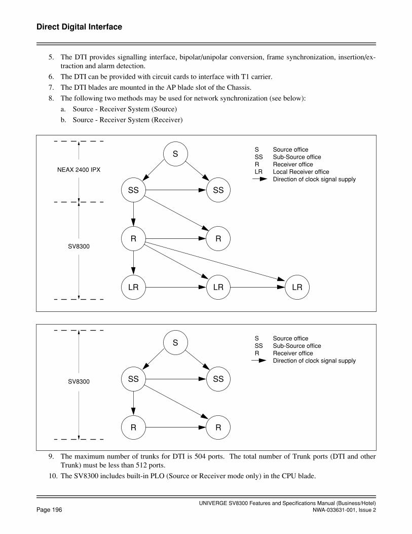
UNIVERGE SV8300 Features and Specifications Manual (Business/Hotel)
Page 196
NWA-033631-001, Issue 2
Direct Digital Interface
5. The DTI provides signalling interface, bipolar/unipolar conversion, frame synchronization, insertion/ex-traction and alarm detection.
6. The DTI can be provided with circuit cards to interface with T1 carrier.
7. The DTI blades are mounted in the AP blade slot of the Chassis.
8. The following two methods may be used for network synchronization (see below):
a. Source - Receiver System (Source)
b. Source - Receiver System (Receiver)
9. The maximum number of trunks for DTI is 504 ports. The total number of Trunk ports (DTI and otherTrunk) must be less than 512 ports.
10. The SV8300 includes built-in PLO (Source or Receiver mode only) in the CPU blade.
R
LR
S
SS SS
R
LR LR
NEAX 2400 IPX
SV8300
S Source officeSS Sub-Source officeR Receiver officeLR Local Receiver office Direction of clock signal supply
R
S
SS SS
R
SV8300
S Source officeSS Sub-Source officeR Receiver office Direction of clock signal supply

UNIVERGE SV8300 Features and Specifications Manual (Business/Hotel)NWA-033631-001, Issue 2
Page 197
Direct Inward Dialing (DID)
Direct Inward Dialing (DID)
General Description
This feature provides for incoming calls from the exchange network (except FX or WATS) to reach any stationwithin the system without attendant assistance.
Station Application
Not applicable.
Operating Procedure
The calling party outside the system dials the appropriate telephone number. The call will ring directly at thecalled station, bypassing the attendant.
Service Conditions
1. This feature is normally used when direct-in service is desired on an extension or system-wide basis.
2. DID must be provided by the serving C.O.; however, not all telephone company C.O. are capable of pro-viding this service.
3. One of the following control signaling methods can be used on incoming DID trunks: immediate start, de-lay start and wink start.
4. Dual-Tone, Multi-Frequency (DTMF) or rotary dial signaling is available. This is assigned on a trunk routebasis.
5. Calls to invalid numbers can be routed to an Attendant, a designated station, or to a recorded announcement.
6. When a station has activated Call Forwarding (all types), the DID call will be forwarded to the designatedstation rather than to the specific station dialed.
7. If the called station is assigned as a pilot in Station Hunting and is busy, the call follows the preset huntingpattern.
8. On an incoming call to a busy station, the Call Forwarding feature takes precedence over the Station Hunt-ing feature. If the Call Forwarding feature and the Station Hunting feature are not activated, the caller willreceive busy tone or will reroute to the Attendant Console, designated station, or recorded announcementdepending on the assignment in system programming.
9. Stations in Do Not Disturb will be provided with visual indication but no audible indication. Secondaryappearances will ring when assigned. The calling party will receive ring back tone until answered.
10. An incoming Listed Directory Number (LDN) received from a DID line can be displayed on the LCD of aMultiline Terminal or an Attendant Console. This system data is assigned on a trunk route basis.
11. The DID incoming LDN display is one digit to four digits.
12. By system programming, the system allows tenant allocation of the following functions, on the basis of re-ceived DID number.
• Destination of no answer calls
• Destination of busy calls
• Destination of dead number calls

UNIVERGE SV8300 Features and Specifications Manual (Business/Hotel)
Page 198
NWA-033631-001, Issue 2
Direct Inward Dialing (DID)
DID Call Waiting
• Destination of Do Not Disturb
• Restriction of inter - tenant connections
• Designation of external Music-on Hold source
DID Call Waiting
General Description
This feature allows an incoming call on a DID trunk or a tie line to automatically be Camped-On to the destina-tion station if the destination station is busy.
Station Application
All stations.
Operating Procedure
The camp-on occurs automatically once this feature is assigned. For details on how to respond to the camp-on,refer to the Camp-On Features and Specifications.
Service Conditions
1. This feature is assigned on a per trunk route basis and on the basis of which number is dialed into the DID/tie trunk.
2. The outside party receives ringback tone while waiting for the station to answer the Camp-On.
3. Refer to the Camp-On Features and Specifications for more information and service conditions related toCamp-On.

UNIVERGE SV8300 Features and Specifications Manual (Business/Hotel)NWA-033631-001, Issue 2
Page 199
Direct Inward Dialing (DID)
DID Digit Conversion
DID Digit Conversion
General Description
This feature allows the system to convert the digits received from the serving C.O. to valid station numberswhen the C.O. numbering plan differs from the desired station numbering plan.
Station Application
Not Applicable.
Operating Procedure
No special operation by station users is required.
Service Conditions
1. Addition and deletion of digits can be implemented to coincide with the existing numbering plan.
2. When digit conversion of DID incoming number has been activated, the number received from the C.O. be-fore conversion is displayed.
3. A DID incoming number can be converted to a PBX station number, by analyzing the last dialed one-eightdigits of DID incoming number. A maximum of 1,000 DID incoming number can be converted to a maxi-mum of 1,000 PBX station number, with one Digit Conversion Table. Using extra Digit Conversion Table, a total of 2,000 DID incoming number can be converted to a maximumof 1,000 PBX station number. See Condition 4 below.
4. The following table shows the comparison between Digit Conversion Tables #0 and #1 for DID incomingnumber.A choice of Digit Conversion Table (Table #0 or #1) can be programmed on a trunk route basis.
5. Digit Conversion Table #1 can be used for trunk calls using DID (analog and T1), ISDN, Caller ID CLASS,and T1-ANI. CCIS calls cannot use the Table #1.
6. Last dialed four digits of DID incoming number can be displayed on the LCD of a Multiline Terminal orAttendant Console in either case (Digit Conversion Table #0 or #1).
Number of Digits to be received on DID
Digit Conversion of DID incoming number
Digit Conversion Block Number
DigitConversionTable #0(standard)
1 to 4 digits Received no. of digitsorLast dialed 2 to 4 digits
Max. 1,000
DigitConversionTable #1(expanded)
1 to 14 digits Last dialed 1 to 8 digits Max. 1,000

UNIVERGE SV8300 Features and Specifications Manual (Business/Hotel)
Page 200
NWA-033631-001, Issue 2October, 2008
Direct Inward Dialing (DID)
DID Name Display
DID Name Display
General Description
This feature allows name assignment for a DID number received from a public network, and displays the nameon an LCD of a Multiline Terminal or Attendant Console.
Station Application
All Multiline Terminals with LCD, and Attendant Consoles.
Operating Procedure
No manual operation is required.
Service Conditions
1. A name assigned for a DID number is registered by a maximum of 16 characters from PC Programmingonly.
2. Up to 200 names can be registered per system.
3. The name will be displayed up to 16 characters in the middle line on the LCD of the Multiline Terminal orAttendant Console.
4. The terminals that can display names are Multiline Terminals, Attendant Consoles and PS stations. Caller ID station displays the calling party number from ISDN, Caller ID Class, and T1-ANI.
5. Name display will be continued as follows after answering calls:
Muitiline Terminals : display for 6 seconds / display continuously (selectable)Attendant Consoles : display for 6 seconds / display continuously (selectable)PS : displayed during ringing and the conversationCaller ID Station : depend on the telephone's specification
6. Display of calling party number or name for DID number can be changed by pressing a Display ChangeKey. If there is no calling number such as DID, only the name for DID number will be displayed.
7. The names for DID number can be displayed by pressing the Number Display Key on Multiline Terminals.
8. When a station transfers the DID call to another station, the name for DID number can be displayed on theLCD of the transferred Multiline Terminal.
9. When the station transfers an incoming call to another station over CCIS, the calling party name for ISDNcan be displayed. Note that the calling party name for Caller ID Class and T1-ANI cannot be transferred over CCIS.
10. This feature has priority over displays for calling party names that are registered in Speed Calling - Station.
11. This feature has priority over calling party number registered in CPU blade as Caller ID.
12. This feature has priority over the name received from Caller ID Network or ISDN Network.
13. This feature is not available for incoming calls via CCIS.
14. Spaces cannot be entered between names.
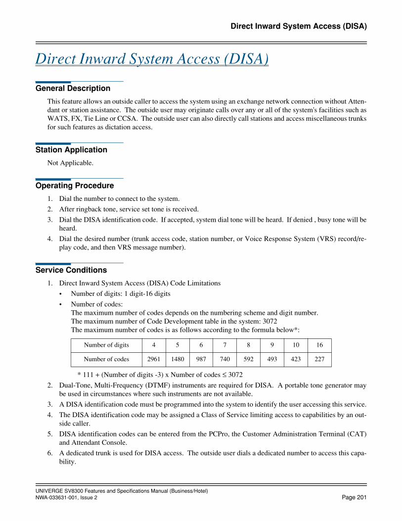
UNIVERGE SV8300 Features and Specifications Manual (Business/Hotel)NWA-033631-001, Issue 2
Page 201
Direct Inward System Access (DISA)
Direct Inward System Access (DISA)
General Description
This feature allows an outside caller to access the system using an exchange network connection without Atten-dant or station assistance. The outside user may originate calls over any or all of the system's facilities such asWATS, FX, Tie Line or CCSA. The outside user can also directly call stations and access miscellaneous trunksfor such features as dictation access.
Station Application
Not Applicable.
Operating Procedure
1. Dial the number to connect to the system.
2. After ringback tone, service set tone is received.
3. Dial the DISA identification code. If accepted, system dial tone will be heard. If denied , busy tone will beheard.
4. Dial the desired number (trunk access code, station number, or Voice Response System (VRS) record/re-play code, and then VRS message number).
Service Conditions
1. Direct Inward System Access (DISA) Code Limitations
• Number of digits: 1 digit-16 digits
• Number of codes: The maximum number of codes depends on the numbering scheme and digit number.The maximum number of Code Development table in the system: 3072The maximum number of codes is as follows according to the formula below*:
* 111 + (Number of digits -3) x Number of codes ≤ 3072
2. Dual-Tone, Multi-Frequency (DTMF) instruments are required for DISA. A portable tone generator maybe used in circumstances where such instruments are not available.
3. A DISA identification code must be programmed into the system to identify the user accessing this service.
4. The DISA identification code may be assigned a Class of Service limiting access to capabilities by an out-side caller.
5. DISA identification codes can be entered from the PCPro, the Customer Administration Terminal (CAT)and Attendant Console.
6. A dedicated trunk is used for DISA access. The outside user dials a dedicated number to access this capa-bility.
Number of digits 4 5 6 7 8 9 10 16
Number of codes 2961 1480 987 740 592 493 423 227

UNIVERGE SV8300 Features and Specifications Manual (Business/Hotel)Page 202 NWA-033631-001, Issue 2
Direct Inward System Access (DISA)Call Forwarding Set by DISA
7. DISA codes can be output in the Station Message Detail Recording (SMDR) record for Tandem Connec-tion.
8. If the called station is busy or does not answer, or the number dialed is a feature access code, any one of thefollowing operations can be set:
• The C.O. line can be released.
• Dial tone can be supplied.
• An alternate call terminating destination (Attendant, Trunk Answer Any Station, Direct Inward Termi-nation) can be provided.
9. The outside user can access a VRS via DISA, if programmed.
Call Forwarding Set by DISA
General Description
This feature allows an outside caller to set Call Forwarding - All Calls by using Direct Inward System Access(DISA) code.
Station Application
Not applicable.
Operating Procedure
To set Call Forwarding - All Calls from outside
1. Dial the number to connect to the system.
2. Dial the DISA identification code after service set tone has received. If denied, busy tone will be heard.
3. Dial the Call Forwarding - All Call feature access code and feature dial tone will be heard. If restricted forthe DISA code, busy tone will be heard.
4. Dial the station number to be forwarded (e.g. 200) and feature dial tone will be heard. If restricted for thestation, busy tone will be heard.
5. Dial trunk access code, the desired target number and “#”.
6. Wait till service set tone is received. If failed, busy tone will be heard.
To cancel Call Forwarding - All Calls from outside
1. Dial the number to connect to the system.
2. Dial the DISA identification code after service set tone has received. If denied, busy tone will be heard.
3. Dial the Call Forwarding - All Call cancellation code and feature dial tone will be heard. (If restricted forthe DISA code, busy tone will be heard.)
4. Dial the station number to be forwarded.
5. Wait till service set tone is heard. If failed, busy tone will be heard.
UNIVERGE SV8300 Features and Specifications Manual (Business/Hotel)NWA-033631-001, Issue 2 Page 203
Direct Inward System Access (DISA)Call Forwarding Set by DISA
Service Conditions
1. Station / Attendant Console / Outside Line (Analog CO Line, Tie Line) can be set as the target for Call For-warding - All Calls.
2. If the target station is outside line, dial trunk access code, the desired target number and “#” at last.
3. Only the trunk access code cannot be registered.
4. “*” is used to separate the code between the target number and called party subaddress.
5. The target number is up to 26 digits including a separate code and a called party subaddress.
6. If timeout occur without dialing “#” after dialing the target number, busy tone will be heard.
7. If a station number is assigned to a DISA code pattern number, only the station can be forwarded any. Ifno station is assigned, all stations can be forwarded.
8. If the station to be forwarded is the main station of the Number Sharing feature, the feature is activated.
UNIVERGE SV8300 Features and Specifications Manual (Business/Hotel)Page 204 NWA-033631-001, Issue 2
Direct Inward Termination (DIT)
Direct Inward Termination (DIT)
General Description
This feature automatically routes incoming network exchange calls directly to a selected station without Atten-dant assistance. The call can then be processed by the called party. Three-party Conference, Call Transfer, etc.,are handled in the same manner as any normal trunk call.
Station Application
All stations.
Operating Procedure
No manual operation is required.
Service Conditions
1. Bothway trunks can be used for Direct Inward Termination, but incoming only trunks are recommended.This minimizes DIT calls meeting busy conditions.
2. If there is no answer at a station, the calling party will continuously receive ringback tone. Call Forwarding- No Answer will occur if set or the calling party will be transferred to the Attendant or Trunk Answer anyStation by system programming if enabled.
3. Once a call is answered, it can be processed by the called station in the same way as any normal trunk call.
4. If the DIT is assigned to a pilot number of a Station Hunting group or Automatic/Uniform Call Distribution(ACD/UCD) group, the incoming call will follow the hunt group station assignment. If the station is CallForwarded, the incoming call is connected to the Call Forward target station according to the types of CallForwarding set and the condition of the DIT station.
5. This feature is normally used where direct-in service is required on a limited basis. The number of stationsthus serviced is limited to the number of trunks available for Direct Inward Termination.
6. Multiple trunks can be assigned to Direct Inward Terminate to an extension, but a trunk cannot be assignedto Direct Inward Terminate to multiple extensions.
7. When the Direct Inward Termination station is busy, the call can be programmed to go either to the Atten-dant, Trunk Answer any Station, or Camp-On. During night mode, the call can be programmed to Camp-On or go directly to Trunk Answer any Station.

UNIVERGE SV8300 Features and Specifications Manual (Business/Hotel)NWA-033631-001, Issue 2 Page 205
Direct Outward Dialing (DOD)
Direct Outward Dialing (DOD)
General Description
This feature permits any station user the ability to gain access to the exchange network by dialing an access codeand receiving new dial tone. The user may then proceed to dial the desired exchange network number.
Station Application
All stations.
Operating Procedure
To place an outside call
From any station
1. Go off-hook and receive extension dial tone.
2. Dial the trunk access code.
3. Receive outside dial tone.
4. Dial the desired outside number.
From a Multiline Terminal
1. Press the Speaker key and receive extension dial tone.
2. Press a trunk appearance line key.
3. Receive outside dial tone.
4. Dial the desired outside number.
Service Conditions
1. Outgoing restriction can be assigned on an individual station basis. Refer to Class of Service.
2. Code Restriction may be applied to Direct Outward Dialing (DOD).
3. Various types of trunks (FX, WATS, Tie, DID, etc.) can be accessed by stations using this feature.
4. The trunk route access code can be one to four digits.
5. Use of the DOD feature can be denied on a per trunk route basis when one of the following restrictions isactive on the originating station line.
• Fully restricted stations: Direct Outward Dialing attempts are routed to reorder tone when the stationis fully restricted.
• Restriction from outgoing calls: A station assigned this feature is denied the ability to access selectedtrunk routes. Attempts are routed to reorder tone.
• Code Restriction: Levels of this feature restrict unauthorized stations the ability to complete outgoingC.O. or foreign exchange calls to a specified area or office codes within an area code. Refer to the LeastCost Routing feature. A station with Toll Denial is routed to reorder tone when a restricted number isdialed after the trunk access code has been dialed.

UNIVERGE SV8300 Features and Specifications Manual (Business/Hotel)Page 206 NWA-033631-001, Issue 2
Direct Outward Dialing (DOD)
6. Exchange network call completion using the Hotline Outside feature is permitted. The originating stationis automatically routed to the assigned trunk route and the digits are dialed automatically when the stationgoes off-hook.
7. This feature is disabled when the switch on the CPU is set to KF registration.

UNIVERGE SV8300 Features and Specifications Manual (Business/Hotel)NWA-033631-001, Issue 2 Page 207
Direct Station Selection/Busy Lamp Field (DSS/BLF) Console
Direct Station Selection/Busy Lamp Field (DSS/BLF) Console
General Description
This feature allows a Direct Station Selection/Busy Lamp Field (DSS/BLF) Console to be associated with aMultiline Terminal. When the buttons on the DSS/BLF Console unit are programmed for Direct Station Selec-tion (DSS) buttons, up to 60 stations can be directly accessed in addition to those already appearing on the Mul-tiline Terminal. Busy status for each station is indicated by a red LED associated with each button.
In addition, the DSS/BLF console can provide the following functions:
• Message Waiting - Set/Cancel/Status Display
• Do Not Disturb - Set/Cancel/Status Display
• Automatic Wake Up No Answer - Status Display/Cancel
• Agent Busy Out - UCD - Status Display
• Line Lockout - Status Display
• Room Cutoff - Set/Cancel/Status
Station Application
All Multiline Terminals.
Operating Procedure
To initiate a call
1. Press the desired DSS key.
2. Lift handset and converse when party answers.
OR
1. Lift handset and receive dial tone.
2. Press the desired DSS key.
3. Converse when party answers.
To display Line Lockout status
No manual operation is required. When stations are currently in Line Lockout mode, their associated LED willflash red at 30 ipm.
Service Conditions
1. A Multiline Terminal can be equipped with as many DSS/BLF Console units as necessary.
2. The maximum number of DSS/BLF Console that can be programmed in the system is 32 (DSS/BLF+Add-On Modules.).
3. A maximum of 60 Direct Station Selection keys can be assigned on each DSS/BLF Console.

UNIVERGE SV8300 Features and Specifications Manual (Business/Hotel)Page 208 NWA-033631-001, Issue 2
October, 2008
Direct Station Selection/Busy Lamp Field (DSS/BLF) Console
4. When a call is made using the DSS/BLF Console, the associated Multiline Terminal's LCD displays thesame indication that is provided for internal calls made from the line keys of the Multiline Terminal.
5. Feature Access keys cannot appear on the DSS/BLF Console.
6. The DSS/BLF Console can be provided with a Message Wait (MW) key, a Do Not Disturb (DND) key, aNight Transfer (NT) key, a Wake Up No Answer (WU) key, a Room Cutoff (RC) key, and a Agent BusyOut (BYO) key for the following purposes:
• MW key Message Waiting Set/Cancel/Status Display • DND key Do Not Disturb Set/Cancel/Status Display • NT key Day/Night mode change for the associated tenant • WU key Automatic Wake Up No Answer Cancel/Status Display • RC key Room Cutoff Set/Cancel/Status Display• BYO key Agent Busy Out - UCD Status DisplayThese keys must be assigned to the last three (3) keys (key no. 57, 58 and 59) on the DSS/BLF Console.
7. Key operation from MW, DND, WU, and BYO key on the DSS/BLF Console are effective for only the first48 DSS keys (key no. 00 to 47), which have two (2) LEDs (red and green) in each key. Direct Station Se-lection, busy status indication, and Line Lockout status indication are effective for all 60 keys on the DSS/BLF Console.
8. When the following operations from the DSS/BLF Console are used, the Function Mode key must be as-signed to one of 60 DSS keys.
• Message Waiting Set/Cancel using MW key.
• Do Not Disturb Set/Cancel using DND key.
• Automatic Wake Up No Answer Cancel using WU key
9. A DLC blade is required when a DSS/BLF Console is installed.The DCL-60-1 Console is directly connected to a DLC blade or is attached to a DT700 SIP Multiline Ter-minal (as a side option, requires AC/DC Adaptor).
When connected as Side-option of DT700
1. It is registered in system data as IP Terminal because it is dealt equal to one DSS Console.
2. It consumes one Capacity license same as TDM connection. But it does not consume IP license.
3. Only connected DT700 can be combined as station. But multiple DSS Consoles in TDM connection canbe combined.So, following patterns of multiple DSS Consoles exist.Station (any) + TDM connection × NStation (DT700) + Side-option × 1 + TDM connection × N
UNIVERGE SV8300 Features and Specifications Manual (Business/Hotel)NWA-033631-001, Issue 2 Page 209
Direct Station Selection/Busy Lamp Field (DSS/BLF) ConsoleBusy Out Status Console
Busy Out Status Console
General Description
This feature allows a DSS/BLF Console unit associated with a Multiline Terminal to be used as a Busy Out Sta-tus Console. This feature is activated by use of a Function Mode key on a DSS/BLF Console. The Busy OutStatus for each station is indicated by a red LED associated with each button.
Station Application
All stations with an associated DSS/BLF Console.
Operating Procedure
To display station Busy Out (BYO) status
1. Press the Function Mode key on the DSS/BLF Console assigned for Busy Out Status display. An LED as-sociated with the BYO key lights.
2. When stations are currently in the Busy Out state, their associated LED will light green.
3. Press the same Function Mode key to return to DSS/BLF mode, if desired.
Service Conditions
1. If the system is initialized (Reset) the Console Function Mode will return to DSS/BLF.
2. The Busy Out Status of a station cannot be set or cancelled from a Busy Out Status Console.
3. Refer to the DSS/BLF Console and the Uniform Call Distribution Features and Specifications for more de-tails.
UNIVERGE SV8300 Features and Specifications Manual (Business/Hotel)Page 210 NWA-033631-001, Issue 2
Direct Station Selection/Busy Lamp Field (DSS/BLF) ConsoleDo Not Disturb Console
Do Not Disturb Console
General Description
This feature allows a DSS/BLF Console associated with a Multiline Terminal to be used as a Do Not Disturb(DND) Console. This feature is activated by the use of a Function Mode key on a DSS/BLF Console. DND setstatus for each station is indicated by a green LED associated with each button. In addition, the Multiline Ter-minal user can set/cancel the DND status of other stations using the DND Console.
Station Application
All stations with a DSS/BLF Console.
Operating Procedure
To set and cancel Do Not Disturb (DND)
1. Press the DND key. When stations are currently in DND their associated LED will light green.
2. Press the Function Mode key: an LED associated with the Function Mode key will light red.
3. Press the desired DSS key(s) to set or cancel. A lit LED indicates DND is set.
4. Press the DND key again to return to DSS/BLF mode, if desired.
Service Conditions
1. The DND Console displays the set status for those stations for whom DND was set, by the station user ofthe DND console or by the set station only. Indication is not provided when another DND Console, theAttendant Console, a Hotel/Motel Front Desk Instrument, or a PMS changes the status of a station.
2. If the system is initialized (reset), the Console function mode will return to DSS/BLF.
3. Refer to the DSS/BLF Console and the Do Not Disturb Features and Specifications for more details.
UNIVERGE SV8300 Features and Specifications Manual (Business/Hotel)NWA-033631-001, Issue 2 Page 211
Direct Station Selection/Busy Lamp Field (DSS/BLF) ConsoleMessage Waiting Console
Message Waiting Console
General Description
This feature allows a DSS/BLF Console associated with a Multiline Terminal to be used as a Message Waiting(MW) Console. This feature is activated by the use of a Function Mode key on a DSS/BLF Console. The Mes-sage Waiting status for each station is indicated by a green LED associated with each button. In addition, theMultiline Terminal user can set/reset MW status using the MW Console.
Station Application
All stations with a DSS/BLF Console.
Operating Procedure
To set and cancel Message Waiting
1. Press the MW key. When stations are in MW their associated LED will light green.
2. Press the Function Mode key: an LED associated with the Function Mode key will light red.
3. Press the desired DSS key(s) to set or cancel. A lit LED indicates MW has been set.
4. Press the MW key again to return to DSS/BLF mode, if desired.
Service Conditions
1. The MW Console only displays/cancels the set status for those stations to whom Message Wait was set, bythe station user of the MW Console.
2. If the system is initialized (reset), the Console function mode will return to DSS/BLF.
3. Refer to the DSS/BLF Console and the Message Waiting Features and Specifications for more details.

UNIVERGE SV8300 Features and Specifications Manual (Business/Hotel)Page 212 NWA-033631-001, Issue 2
Direct Station Selection/Busy Lamp Field (DSS/BLF) ConsoleRoom Cutoff Console
Room Cutoff Console
General Description
This feature allows a DSS/BLF Console associated with a Multiline Terminal to be used as a Room Cutoff Con-sole. This feature is activated by the use of a Function Mode key on a DSS/BLF Console. The Room Cutoffstatus for each station is indicated by a green LED associated with each button. In addition, the Multiline Ter-minal user can set/cancel Room Cutoff to another station using the Room Cutoff Console.
Station Application
All Multiline Terminals with a DSS/BLF Console.
Operating Procedure
To set and cancel Room Cutoff
1. Press the RC key. When stations are in RC their associated LED will light green.
2. Press the Function Mode key. An LED associated with the Function Mode key will light red.
3. Press the desired DSS key(s) to set or cancel. A lit LED indicates RC has been set.
4. Press the RC key again to return to the DSS/BLF mode, if desired.
Service Conditions
1. The Room Cutoff Console only displays/cancels the set status for those stations that were set into room cut-off by the station user of the Room Cutoff Console. Indication is not provided when another Room Cutoffconsole, the Attendant Console, a Hotel/Motel Front Desk Instrument, or a PMS changes the RC status ofa station.
2. If the system is initialized (reset), the Console function mode returns to DSS/BLF.
3. Refer to the DSS/BLF Console and the Room Cutoff Features and Specifications for more details.
UNIVERGE SV8300 Features and Specifications Manual (Business/Hotel)NWA-033631-001, Issue 2 Page 213
Direct Station Selection/Busy Lamp Field (DSS/BLF) ConsoleWake Up No Answer Console
Wake Up No Answer Console
General Description
This feature allows a DSS/BLF Console associated with a Multiline Terminal to be used as a Wake Up No An-swer (WU) Console. This feature is activated by a function mode key on a DSS/BLF Console. The No Answerstatus for each station is indicated by a flashing green LED associated with each button.
Station Application
All Multiline Terminals with a DSS/BLF Console.
Operating Procedure
To display and cancel Wake Up No Answer
1. Press the WU key. If a station fails to answer its wake up call, its associated LED flashes green at 30 ipm.
2. Press the Function Mode key: an LED associated with the Function Mode key will light red.
3. Press the flashing DSS key(s) to turn out the desired station's LED.
4. Press the WU key again to return to the DSS/BLF mode, if desired.
Service Conditions
1. The Wake Up No Answer Console is only used to display/cancel the No Answer status of the AutomaticWake Up feature after the station has failed to answer. The Automatic Wake Up feature cannot be set fromthe Wake Up No Answer Console.
2. If the system is initialized (reset), the Console function mode will return to DSS/BLF.
3. Refer to the DSS/BLF Console and the Automatic Wake Up Features and Specifications for more details.

UNIVERGE SV8300 Features and Specifications Manual (Business/Hotel)Page 214 NWA-033631-001, Issue 2
Distinctive Ringing
Distinctive Ringing
General Description
This feature provides Distinctive Ringing patterns to the station so that the station user can distinguish betweeninternal and external incoming calls. This feature also enables the LED associated with the line key of the Mul-tiline Terminal to flash in two colors according to the kind of incoming call.
Station Application
All stations.
Operating Procedure
No manual operation is required.
Service Conditions
1. Ringing pattern for incoming internal calls:
1 second on, 2 seconds off
OR
2 seconds on, 4 seconds off.
2. Ringing pattern for incoming external calls:
1 second on, 2 seconds off
OR
2 seconds on, 4 seconds off.
OR
0.4 seconds on, 0.2 seconds off0.4 seconds on, 2.0 seconds off
Calls to Multiline Terminals
1 second on, 2 seconds off
OR
2 seconds on, 4seconds off
OR
0.4 seconds on, 0.2 seconds off
0.4 seconds on, 2.0 seconds off
3. Ringing pattern for Call Back, Trunk Queuing - Outgoing and Executive Calling:
0.5 seconds on, 0.5 seconds off0.5 seconds on, 1.5 seconds off.
4. All recalls (to Multiline Terminals):
0.5 seconds on, 0.5 seconds off0.5 seconds on, 0.5 seconds off.

UNIVERGE SV8300 Features and Specifications Manual (Business/Hotel)NWA-033631-001, Issue 2 Page 215
Distinctive Ringing
5. When calling a third station (three-party Conference, Consultation Hold, etc.), the ringing signal sent to thecalled station is dependent upon the type of call placed on Hold. If the call is a trunk call, external ringingis provided; if the call is an extension call, internal ringing is provided.
6. Ring frequencies of Multiline Terminals can be assigned in programming through station Class of Service.Refer to the Ring Frequency Control Features and Specifications.
7. The ringing pattern for incoming internal calls is programmable on a system basis.
8. The ringing pattern for incoming external calls is programmable on per trunk route basis or a received DIDnumber basis.
9. The ringing pattern for incoming external calls in the following manners is programmable on a trunk routebasis or a received DID number basis.
• An incoming external call directly to a station
• A station call with an incoming external call placed in Consultation Hold
• An incoming external call to a Multiline Terminal with Delayed Ringing
• An incoming external call forwarded by Call Forwarding-No Answer
• An incoming external call after queued in UCD queuing
10. The ringing pattern of recalls to Single Line Telephones is the same pattern as that of the original call.
11. The distinctive LED indication is applicable only for Multiline Terminals during call termination (includinga recall).
12. The LED indication patterns are as follows:
• Incoming internal calls Red, 120-ipm flashing
• Incoming external calls Green or Red, 120-ipm flashing
The lamp color for incoming external calls can be selected to be green or red.
13. The lamp color for incoming external calls can be designated on a per-trunk-route basis.
14. The distinctive LED indication is valid for Direct Inward Termination, Automated Attendant, Direct InwardDialing, and Tie line incoming call.
15. The flashing lamp color depends on system data (assigned for Distinctive Ringing) and is used to indicatethe termination of a transferred external incoming call.
16. If the system is installed behind Centrex or the main PBX, this feature provides Distinctive Ringing patternsto the Multiline Terminal in the system so that the station user can distinguish between internal calls fromthe main PBX and external incoming calls. The C.O. trunk to the main PBX must be assigned on Trunk -Direct Appearances on the Multiline Terminal.
17. When Distinctive Ringing in behind system is activated, Delayed Ringing is not available for the relatedC.O. trunk.

UNIVERGE SV8300 Features and Specifications Manual (Business/Hotel)Page 216 NWA-033631-001, Issue 2
Do Not Disturb
Do Not Disturb
General Description
This feature restricts incoming calls to a station and can be set by an individual station or from the AttendantConsole. Placing a station in Do Not Disturb (DND) does not prevent a station from originating a voice or datacall or from receiving a data call. This feature also allows a station to ensure privacy from telephone interrup-tions while on an outgoing call. Additionally, the Attendant Console can place a group of stations in the Do NotDisturb condition.
Station Application
All stations.
Operating Procedure
From a Single Line Telephone
To set
1. Lift the handset and receive dial tone.
2. Dial the Do Not Disturb feature access code and receive service set tone.
3. Restore the handset.
To cancel
1. Lift the handset and receive dial tone.
2. Dial the Do Not Disturb cancel code and receive service set tone.
3. Restore the handset.
From a Multiline Terminal
To set
1. Lift the handset or press the Speaker key and receive dial tone.
2. Press the DND function key and the associated LED lights. If equipped with an LCD the display will indi-cate SET.
3. Replace the handset or press the Speaker key.
To cancel
1. Lift the handset or press the Speaker key and receive dial tone.
2. Press the DND function key and the associated LED goes out. If equipped with an LCD the display willindicate CANCEL.
3. Replace the handset or press the Speaker key.
To call a station that set DND (DND Override)
1. Lift the handset or press the Speaker key and receive dial tone.

UNIVERGE SV8300 Features and Specifications Manual (Business/Hotel)NWA-033631-001, Issue 2 Page 217
Do Not Disturb
2. Dial the station number and the DD LED flashes and reorder tone is received.
3. Press the DDOVR key.
4. The station will ring.
From the Attendant Console
To set an individual station in DND
1. Dial the desired station number.
2. Press the DD key and the associated LED flashes.
3. Press the START key. The DD LED lights steadily and service set tone is received.
4. Press the RELEASE key.
To cancel an individual station in DND
1. Dial the desired station number.
2. Press the DD key and the associated LED flashes.
3. Press the RESET key and the DD LED goes out.
4. Press the RELEASE key.
To set a group of stations in DND
1. Press the DD key and the associated LED flashes.
2. Press the START key and the DD LED lights steadily.
3. The designated group is now in DND.
To cancel a group of stations in DND
1. Press the DD key and the associated LED flashes.
2. Press the RESET key and the DD LED goes out.
3. The designated group is no longer in DND.
To call a station that set DND (DND Override)
1. Press an idle LOOP key.
2. Dial the station number and the DD LED flashes and reorder tone is received.
3. Press the DDOVR key.
4. The station will ring.
To set DND to a Sub Line from a Multiline Terminal
1. When the Multiline Terminal is idle, press the Sub Line key for which DND is to be set, and hear dial tone.
2. Dial the DND feature access code and receive service set tone. If equipped with an LCD, the display willindicate SET.
OR
Press the DND function key and the associated LED lights, and receive service set tone. If equipped withan LCD, the display will indicate SET.
OR
Press the DND Soft key and receive service set tone. The LCD will indicate SET.
UNIVERGE SV8300 Features and Specifications Manual (Business/Hotel)Page 218 NWA-033631-001, Issue 2
Do Not Disturb
3. Replace the handset or press the Speaker key.
To cancel DND in a Sub Line from a Multiline Terminal
1. When the Multiline Terminal is idle, press the Sub Line key for which DND is to be set, and hear dial tone.
2. Dial the DND cancel code and receive service set tone. If equipped with an LCD, the display will indicateCANCEL.
OR
Press the DND function key and the associated LED goes out, and receive service set tone. If equipped withan LCD, the display will indicate CANCEL.
OR
Press the DND Soft key and receive service set tone. The LCD will indicate CANCEL.
3. Replace the handset or press the Speaker key.
Service Conditions
1. Calls to stations that are in Do Not Disturb will receive reorder tone or--on a tenant basis--can be assignedto transfer to the Attendant or a designated station.
2. The station in Do Not Disturb can originate calls in the normal manner.
3. Call Forwarding can be set to a station in Do Not Disturb.
4. A Do Not Disturb station will be omitted from the Station Hunting chain. If a DIT call is directed to a pilotof a hunt group, hunting will be provided. Internal calls will receive a fast busy tone.
5. The Do Not Disturb station can cancel DND even though the condition was set by the Attendant.
6. Verification of stations in Do Not Disturb is only possible from the Attendant Console. Multiline Terminalswith LCD and a DND key assigned can verify their own DND setting.
7. The ability to set DND can be controlled on a per station via Class of Service or a per system basis.
8. This feature can only be set or canceled by the station while the station is receiving internal dial tone.
9. When a Multiline Terminal is set in DND, calls to the primary extension and secondary extensions will notring. Trunks programmed to ring will not do so while DND is set, but flashing LED indications are stillprovided. DND will not deny an Executive Override.
10. An Attendant or a Multiline Terminal can override DND setting to call a station which has set DND.
11. Only the Attendant has the ability to place a group of stations in Do Not Disturb. There is only one groupavailable and the stations within the group are programmed in system data. There is no limitation on thenumber of stations in the group.
12. A station included in a DND group, retains the ability to place their particular station in DND.
13. When the Attendant places a group in DND, an individual station within the group can cancel the DND set-ting to their station.
14. A feature access line key can be assigned on Multiline Terminals for DND set and cancel.
15. If the DND key is pressed while connected to a trunk or station, the following interruptions are denied untilthat call is completed:
• Attendant Camp-On• Attendant Override• Boss Secretary Override• Camp-On

UNIVERGE SV8300 Features and Specifications Manual (Business/Hotel)NWA-033631-001, Issue 2 Page 219
Do Not Disturb
• Executive Override
16. Refer also to the Hotel/Motel Do Not Disturb feature.
17. DND is displayed on a Multiline Terminal with LCD, when calling a station in DND through intra-officeor over CCIS.
18. The priority for service checks (features activated) on a station is as follows:
a. Call Forwarding - All Calls
b. Call Forwarding - Busy Line
c. Station Hunting/UCD
d. Do Not Disturb
19. When a call is transferred to an outside number, an outgoing trunk is chosen depending on the tenant of DoNot Disturb station, and Toll Restriction is followed by that of the class of Do Not Disturb station.
20. When a call is transferred to an outside number, SMDR will charge to the station that sets Do Not Disturb.
21. When transferring a call via CCIS, the number of the station that sets Do Not Disturb will be displayed asan intermediate station and the type of transfer will be Call Forwarding - Busy Line.
22. If all trunks are in busy status, or if trunk connection is restricted by Toll Restriction, a calling party willhear Busy Tone. And even if a calling party is an Attendant or a Digital Multiline Terminal, it cannot over-ride to the station that sets Do Not Disturb, by pressing DDOVR key.
23. If an Attendant calls a station which set Do Not Disturb, the call will not be transferred.
24. If Return Message Schedule is set, a call terminated from trunk will be transferred to outside number. Aninternal call cannot be transferred.
Conditions for DND Setting to Sub Line and DND Multiline Key Indication
1. A Multiline Terminal user can set/cancel Do Not Disturb (DND) to Sub Line including Virtual line, in ad-dition to My Line. For example, if only few group members are present at night, a user can set a suitablenumber of Sub Lines for the number of attended persons at that time by DND set/cancel from the MultilineTerminal, to prevent incoming calls from being kept ringing and not answered.
2. A Multiline Terminal user can check whether DND has been set for each Sub Line (including virtual lines)accommodated in the Multiline Terminal, with Sub Line key lamps.
3. Conditions for DND setting for stations which set DND
a. The stations that can set DND are Multiline Terminal and IP Multiline Terminal.
b. A Multiline Terminal can set DND for only Sub Lines seized when My Line is idle. DND cannot beset for the Sub Lines if they are used.
4. Conditions for DND setting for stations for which DND is set
a. The stations for which DND can be set are Single Line Telephone, Multiline Terminal, IP Multiline Terminal, and virtual line.
b. Stations for which DND is set have the same conditions as when the existing Do Not Disturb functionis set for My Line by themselves. That is, they reject calls from other stations or trunks.
5. Conditions for DND Multiline Key Indication
a. When a Multiline key is accommodated at the flexible function button of the Multiline Terminal/IP Multiline Terminal, the lamp for the line flashes red in short interval, if the line is set for DND.
b. DND Multiline key indication is enabled only if the line is idle. If the line is used, the lamp canindicate the state of the line.Line busy = lighting in red
UNIVERGE SV8300 Features and Specifications Manual (Business/Hotel)Page 220 NWA-033631-001, Issue 2
Do Not Disturb
Line seized on the terminal = lighting in greenCall incoming on the line = flashing in red
c. DND Multiline key indication is continued even when the following actions are made: Systeminitialization, Multiline Terminal cable disconnection and connection, and logout and login on the IPMultiline Terminal.
d. The number of flexible function buttons of each Multiline Terminal for DND indication is determinedaccording to the system data for the Multiline Terminal.
e. If Sub Lines for DND indication are added to or changed from flexible function buttons of MultilineTerminal, the lamp of the corresponding key is turned off. The LED indication is updated by, for theMultiline Terminal, disconnecting and then connecting its cable or by, for the IP Multiline Terminal,logging out and then logging in on it.
6. Conditions with Other Services
a. Do Not Disturb from My LineIf Do Not Disturb is set from a Single Line Telephone or Multiline Terminal with My Line seized, LED indication of DND status (flashing red in short interval) is also available on each Multiline Terminal that accommodates that line in Multiline.
b. Message Waiting (MW) Multiline Key LED IndicationIt is impossible to use the MW and DND lamps together for the same line key at a time. It is requiredto select which lamp is used for DND or MW indication on each station by system dataprogramming. Message Waiting function supports the indication (lighting red or flashing red at longintervals) of the Multiline key where Message Waiting has been set.
c. DSS Console Lamp ControlWhile DND is set for a Sub Line, a DSS console lamp (Do Not Disturb) of the corresponding stationturns on. If it is canceled, the lamp turns off.
d. Hotel/Motel Attendant ConsoleWhile DND is set for a Sub Line, using hotel functions on the attendant console, the DND functionkey on the attendant console turns on. If it is canceled, the lamp turns off.

UNIVERGE SV8300 Features and Specifications Manual (Business/Hotel)NWA-033631-001, Issue 2 Page 221
Do Not DisturbDo Not Disturb - Hotel/Motel
Do Not Disturb - Hotel/Motel
General Description
This feature allows the Attendant Console(s), Hotel/Motel Front Desk Instrument(s), guest stations or PropertyManagement System (PMS) terminal(s) to place individual stations into Do Not Disturb. Calls can be placedfrom stations set in DND.
Station Application
All stations.
Operating Procedure
From the Hotel/Motel Front Desk Instrument
To set Do Not Disturb
1. Press the DD key.
2. Dial the desired station number.
3. Press the SET key.
4. The above two steps can be repeated for additional stations.
5. Press the RLS key.
To cancel Do Not Disturb
1. Press the DD key.
2. Dial the desired station number.
3. Press the RESET key.
4. The above two steps can be repeated for additional stations.
5. Press the RLS key.
To set Do Not Disturb to the station currently connected
1. Press the DD key.
2. Press the SET key.
3. Press the RLS key.
To cancel Do Not Disturb to the station currently connected
1. Press the DD key.
2. Press the RESET key.
3. Press the RLS key.
From a guest station or administrative station
To set Do Not Disturb
1. Go off-hook and receive dial tone.
UNIVERGE SV8300 Features and Specifications Manual (Business/Hotel)Page 222 NWA-033631-001, Issue 2
Do Not DisturbDo Not Disturb - Hotel/Motel
2. Dial the Do Not Disturb setting code.
3. Receive service set tone and restore the handset.
To cancel Do Not Disturb
1. Go off-hook and receive dial tone.
2. Dial the Do Not Disturb cancellation code.
3. Receive service set tone and restore the handset.
Service Conditions
1. Automatic Wake Up and Timed Reminder will override Do Not Disturb.
2. A station in Do Not Disturb can be called from the Attendant Console or the Hotel/Motel Front Desk In-strument using the DDOVR key.
3. Do Not Disturb is automatically cleared when Check Out is performed.4. Depending on system programming, an incoming call addressed to a station in DND condition is routed to
one of the following on a per-tenant basis:
• Reorder tone
• Attendant Console
• A designated station
5. Refer to Attendant Console and Hotel/Motel Front Desk Instrument Features and Specifications for addi-tional information on Do Not Disturb.
6. When a member station within a Station Hunting group is in DND, calls will bypass the member station andcontinue hunting. A pilot station in DND places the Hunt group in DND.
7. Call Forwarding - Busy settings by stations in DND will result in calls being forwarded, even if the stationsare idle.
8. Message Waiting and Message Reminder cannot be set to stations in DND during conversation.9. Call Back cannot be set to stations in DND.
10. Recalls will override the DND setting, and ring back to a station in DND.

UNIVERGE SV8300 Features and Specifications Manual (Business/Hotel)NWA-033631-001, Issue 2 Page 223
Do Not DisturbDo Not Disturb - System
Do Not Disturb - System
General Description
This feature simultaneously restricts incoming calls to an assigned group of stations by operation from the Ho-tel/Motel Front Desk Instrument(s). Attendant Console(s) and Hotel/Motel Front Desk Instruments can use theDND OVR key to override this Do Not Disturb setting.
Station Application
All stations.
Operating Procedure
To set Do Not Disturb - System from the Hotel/Motel Front Desk Instrument
1. Press the DD key.
2. Press the GROUP key.
3. Press the SET key.
4. Press the RLS key.
To cancel Do Not Disturb - System from the Hotel/Motel Front Desk Instrument
1. Press the DD key.
2. Press the GROUP key.
3. Press the RESET key.
4. Press the RLS key.
Service Conditions
1. Stations are assigned to the Do Not Disturb (DND) Group in Class of Service.
2. Calls to extensions whose stations are in Do Not Disturb will receive reorder tone.
3. The station in Do Not Disturb can originate calls in the normal manner.
4. Verification of stations in Do Not Disturb is possible from the Hotel/Motel Front Desk Instrument and At-tendant Consoles.
5. The ability to set DND is both on a per-station basis, and a per-system (for DND group) basis.
6. Only Hotel/Motel Front Desk Instruments and Attendant Consoles have the ability to place a group of sta-tions in Do Not Disturb. There is only one group available, and the stations within the group are pro-grammed in system data. There is no limitation on the number of stations in the group.
7. A station included in a DND group retains the ability to place that particular station in DND.
8. When the Hotel/Motel Front Desk Instrument places a group in DND, an individual station within the groupcan cancel the DND setting to that station.
9. Refer to the Hotel/Motel Front Desk Instrument Features and Specifications for more information.
10. Refer to Do Not Disturb Features and Specifications for the interactions between DND and system features.

UNIVERGE SV8300 Features and Specifications Manual (Business/Hotel)Page 224 NWA-033631-001, Issue 2
Elapsed Call Timer
Elapsed Call Timer
General Description
This feature provides a display of the elapsed time while a Multiline Terminal with LCD is connected to anytrunk.
Station Application
All Multiline Terminals with LCD.
Operating Procedure
No manual operation is required.
Service Conditions
1. The elapsed time is displayed in the seven upper left-hand positions of the LCD.
2. The elapsed time can reach a maximum of 9 hours, 59 minutes and 59 seconds after which the clock resetsto zero.
3. When a call is placed on Consultation Hold, Exclusive Hold, and Nonexclusive Hold, the elapsed time dis-play will disappear. The Elapsed Call Timer will not reset to zero when a call is retrieved from Hold (Con-sultation Hold, Exclusive Hold, or Nonexclusive Hold) by the same station.
4. When a call is transferred or parked, the time display of the party receiving the transfer begins at zero.
5. The elapsed time is not displayed when the station is in a Conference.

UNIVERGE SV8300 Features and Specifications Manual (Business/Hotel)NWA-033631-001, Issue 2 Page 225
Enhanced 911
Enhanced 911
General Description
This feature allows the PBX to transmit a callers’ emergency service identification information to an Enhanced911 Emergency system. The 911 notification is also provided to the EMG key of a designated Attendant Con-sole/Multiline Terminal.
Station Application
All stations and Attendant Consoles.
Operating Procedure
To initiate 911 Emergency Call
1. Lift the handset and receive a dial tone.
2. Dial the trunk access code and telephone number (e.g. 911).
3. The system automatically completes a call and sends the pre-assigned number: calling area code + callingstation number.
Notification to Attendant Console
1. At designated Attendant Console, the LED of EMG key flashes and ringing is heard.
2. Press both idle LOOP key and EMG key; the caller’s information is displayed.
3. Press BV key; the attendant can override the call.
Notification to Multiline Terminal
1. At designated Multiline Terminal, the LED of EMG key flashes in red and ringing is heard.
2. Lift the handset or press Speaker key, and press EMG key; the caller’s information is displayed.
3. Press Override key; the Multiline Terminal can override the call.
Service Conditions
1. Up to four 911 Sender trunks can be accommodated in the system that includes a T1-ANI/Caller IDReceiver trunk.
2. The caller’s telephone number must be sent in Automatic Number Identification (ANI) format,corresponding to Centralized Message Accounting (CAMA) standards. A trunk circuit capable ofperforming these functions is called a CAMA type trunk.
3. The calling station in the system will receive ROT if there is a Central Office line failure on the CAMAtrunks.
4. If the system has multiple CAMA trunks and the calling station receives ROT due to a Central Office linefailure, the calling station must go on hook and then attempt the call again.
With system data for the CAMA trunk route, the PBX will select the next available CAMA trunk.
Note: For this purpose, it is recommended that the system has a minimum of two CAMA trunks for Enhanced
UNIVERGE SV8300 Features and Specifications Manual (Business/Hotel)Page 226 NWA-033631-001, Issue 2
Enhanced 911
911.
5. The physical interface for Enhanced 911 can be any of the following:
• Digital (T1) configured as Loop Start or E&M type lines (DTI)
• Analog E&M type lines (ODT)
• Analog Loop Start lines (COT)
Note: These lines must be ordered from the Central Office as CAMA type trunks.
Notification to Attendant Console
1. Up to two Attendant Consoles/Multiline Terminals can be assigned per system. The Attendant Consoles/Multiline Terminals can display the caller’s information simultaneously, but only one Attendant Console/Multiline Terminal can override the call.
2. The following routes are available.
a. 911
b. ISDN
c. C.O. Line
d. CCIS
e. Tie Line
3. The following caller’s information can be displayed.
a. The state of a caller
b. Station number/ Kind of trunk
4. If multiple emergency calls are placed simultaneously in the multiple stations/trunks, up to eight calls canbe displayed. In this case, the next caller’s information can be displayed by pressing both idle Loop key andEMG key again, or for Multiline Terminal by pressing EMG key again.
5. Once an attendant/Multiline Terminal overrides the call, the caller’s information cannot be displayed again.
UNIVERGE SV8300 Features and Specifications Manual (Business/Hotel)NWA-033631-001, Issue 2 Page 227
Executive Calling
Executive Calling
General Description
This feature allows a station to be assigned a VIP class. This provides special ringing to a called station whenthat station is idle. It automatically sends three tone bursts to a called station when that station is busy, if the callwas originated from a station assigned as VIP class.
Station Application
All stations.
Operating Procedure
To initiate an Executive Call
1. The station assigned as VIP class goes off-hook.
2. The station dials another extension.
3. If the called station is busy, three tone bursts will be sent to the called party to indicate there is a call waiting.The called party can now hang up and answer the Executive Call.
4. If the called station is idle, a distinctive ring will be sent to the called party to indicate an Executive Call isringing in.
Service Conditions
1. Executive Calling (VIP class) is assigned in Class of Service.
2. This feature is station based. This feature applies only when a station assigned for VIP class is used.
3. When a Single Line Telephone's extension is assigned as VIP class, all internal calls originated from thatstation are Executive Calls.
UNIVERGE SV8300 Features and Specifications Manual (Business/Hotel)Page 228 NWA-033631-001, Issue 2
Executive Override
Executive Override
General Description
This feature allows selected users to override a busy condition on a called station. A warning tone is transmittedto both stations in the busy call before the busy condition is overridden, and a three-party Conference is thenestablished.
Station Application
All stations.
Operating Procedure
From a Multiline Terminal
1. When busy tone is heard, press the key assigned for Executive Override. The associated LED lights and awarning tone is transmitted to both parties.
2. The Multiline Terminal is now bridged into a three-party Conference.
From a Single Line Telephone
1. When busy tone is heard, press the FLASH key (or momentarily press the hookswitch) and receive featuredial tone.
2. Dial the Executive Override feature access code. A warning tone is transmitted to both parties.
3. The station is now bridged into a three-party Conference.
Service Conditions
1. Two 0.8-second tones are transmitted upon activation to alert the connected parties that an Executive Over-ride will occur. On a system-wide basis the tones transmitted to the Analog CO Line may be denied. Thestation will still receive alert tones.
2. When a three-party Conference is established and one party hangs up, the remaining two parties are stillconnected.
3. The Executive Override access code is flexible and can be assigned in system programming.
4. The maximum number of simultaneous Executive Overrides per system is sixteen.
5. If the called station has set the Call Forwarding - Busy/All Calls feature, and the target station is also busy,the Executive Override will interrupt the originally dialed station. If the target station is not busy, the callwill be forwarded.
6. Executive Override can be set when the busy station is connected to another station or a trunk in a two-partyconnection.
UNIVERGE SV8300 Features and Specifications Manual (Business/Hotel)NWA-033631-001, Issue 2 Page 229
Executive Override
7. Executive Override is denied if the busy station is
• dialing
• in Line Lockout mode
• receiving a system generated tone
• protected against Executive Override in Class of Service
• protected against any override by DND key
or when any of the following features is in progress:
• Attendant Override • Consultation Hold • Call Back
• Data Line Security • Hold • Paging
• Call Transfer • Privacy • Camp-On
• Trunk Queuing - Outgoing • Conference • Voice Call
8. When Executive Override is denied, the caller will receive reorder tone.
UNIVERGE SV8300 Features and Specifications Manual (Business/Hotel)Page 230 NWA-033631-001, Issue 2
October, 2008
External Paging with Meet-Me
External Paging with Meet-Me
General Description
This feature allows a station user or attendant dial-access to local voice paging equipment and connects bothparties automatically after the paged party has answered the page by dialing Meet-Me access code or ExternalPaging station number.
Station Application
All stations and Attendant Consoles.
Operating Procedure
To page
From any station
1. The calling station dials External Paging station number and receives service set tone for two seconds.
2. The calling station pages desired party.
3. The calling station remains off-hook or hangs up.
From an Attendant Console
1. Place the incoming call on hold by pressing Hold key.
2. Seize an idle LOOP key.
3. Dial the External Paging station number and receive service set tone for two seconds.
4. Page the desired party.
5. Press the RELEASE key.
To answer
From any station (Non-delay operation : when the calling party remains off-hook)
1. The paged party dials the Meet-Me access code or External Paging station number.
2. The paged party is immediately connected to the calling party.
From any station (Delay operation : when the calling party hangs up)
1. The paged party dials Meet-Me access code or External Paging station number.
2. The party paged receives ringback tone.
3. The calling station rings.
4. The calling station goes off-hook and is immediately connected to the paged party.

UNIVERGE SV8300 Features and Specifications Manual (Business/Hotel)NWA-033631-001, Issue 2 Page 231
October, 2008
External Paging with Meet-Me
Service Conditions
1. Amplifiers and speakers must be provided locally.
2. One 2PGDAD module with a DLC blade is required for every two zones of external paging.
3. Meet-Me codes must be programmed. Answer by dialing External Paging station number is also availableby the system data assignment.
4. A maximum of 10 zones of external paging can be set up.
5. The default of paging period is set to 180 seconds.It can be changed by system data assignment.
6. In a case of delay operation, a system timer (five minutes fixed) starts counting down after the calling partyhangs up. After the timer expires, Meet-Me attempts will be denied and the paging circuits become avail-able again.
7. An Attendant Console cannot answer paging. The terminals that can answer paging are Multiline Terminal,IP Multiline Station (including Soft phone), Single Line Telephone and PS.
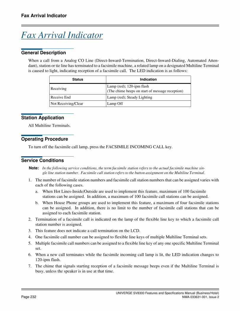
UNIVERGE SV8300 Features and Specifications Manual (Business/Hotel)Page 232 NWA-033631-001, Issue 2
Fax Arrival Indicator
Fax Arrival Indicator
General Description
When a call from a Analog CO Line (Direct-Inward-Termination, Direct-Inward-Dialing, Automated Atten-dant), station or tie line has terminated to a facsimile machine, a related lamp on a designated Multiline Terminalis caused to light, indicating reception of a facsimile call. The LED indication is as follows:
Station Application
All Multiline Terminals.
Operating Procedure
To turn off the facsimile call lamp, press the FACSIMILE INCOMING CALL key.
Service Conditions
Note: In the following service conditions, the term facsimile station refers to the actual facsimile machine sin-gle line station number. Facsimile call station refers to the button assignment on the Multiline Terminal.
1. The number of facsimile station numbers and facsimile call station numbers that can be assigned varies witheach of the following cases.
a. When Hot Lines-Inside/Outside are used to implement this feature, maximum of 100 facsimile stations can be assigned. In addition, a maximum of 100 facsimile call stations can be assigned.
b. When House Phone groups are used to implement this feature, a maximum of four facsimile stationscan be assigned. In addition, there is no limit to the number of facsimile call stations that can beassigned to each facsimile station.
2. Termination of a facsimile call is indicated on the lamp of the flexible line key to which a facsimile callstation number is assigned.
3. This feature does not indicate a call termination on the LCD.
4. One facsimile call number can be assigned to flexible line keys of multiple Multiline Terminal sets.
5. Multiple facsimile call numbers can be assigned to a flexible line key of any one specific Multiline Terminalset.
6. When a new call terminates while the facsimile incoming call lamp is lit, the LED indication changes to120-ipm flash.
7. The chime that signals starting reception of a facsimile message beeps even if the Multiline Terminal isbusy, unless the speaker is in use at that time.
Status Indication
ReceivingLamp (red); 120-ipm flash(The chime beeps on start of message reception)
Receive End Lamp (red); Steady Lighting
Not Receiving/Clear Lamp Off
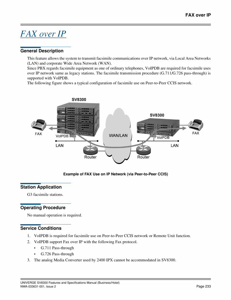
UNIVERGE SV8300 Features and Specifications Manual (Business/Hotel)NWA-033631-001, Issue 2 Page 233
FAX over IP
FAX over IP
General Description
This feature allows the system to transmit facsimile communications over IP network, via Local Area Networks(LAN) and corporate Wide Area Network (WAN).Since PBX regards facsimile equipment as one of ordinary telephones, VoIPDB are required for facsimile usesover IP network same as legacy stations. The facsimile transmission procedure (G.711/G.726 pass-through) issupported with VoIPDB.The following figure shows a typical configuration of facsimile use on Peer-to-Peer CCIS network.
Example of FAX Use on IP Network (via Peer-to-Peer CCIS)
Station Application
G3 facsimile stations.
Operating Procedure
No manual operation is required.
Service Conditions
1. VoIPDB is required for facsimile use on Peer-to-Peer CCIS network or Remote Unit function.
2. VoIPDB support Fax over IP with the following Fax protocol.
• G.711 Pass-through
• G.726 Pass-through
3. The analog Media Converter used by 2400 IPX cannot be accommodated in SV8300.
UNIVERGE SV8300 Features and Specifications Manual (Business/Hotel)Page 234 NWA-033631-001, Issue 2
FAX over IP
4. A problem may occur such as “expected transmission speed is not obtained” or “not connectable”, depend-ing on a facsimile model.
5. If a Super G3 facsimile is used, the transmission speed will be equivalent to G3.
6. If a facsimile with Error Correction Mode (ECM) function is used, ECM does not work.
7. Connectable combinations between facsimile stations are shown below.
8. Required bandwidth for FAX Connection (default setting) are show below.
9. Fax communication mode of VoIPDB is G.711 in default. To set the voice pass-through mode, Fax relateddata setting is required in system data programming.
Connectable CombinationsRemarks
Source Via Destination
SV8300 FAX station Local SV8300 FAX station Station-to-Station connection
SV8300 FAX station Peer-to-Peer CCIS SV8300 FAX station
SV8300 FAX station Peer-to-Peer CCIS 2400 IPX FAX station
SV8300 FAX station Peer-to-Peer CCIS2400 IPX MC FAX station
Connection Conditions Required Bandwidth (One-way)
G.711 pass-through, Payload=40 ms(No IP Header compression in Router)
72 kbps (FAX Payload=320 byte)
G.711 pass-through, Payload=40 ms(with IP Header compression in Router)
65 kbps (FAX Payload=320 byte)
G.726 pass-through, Payload=40 ms(No IP Header compression in Router)
40 kbps (FAX Payload=160 byte)
G.726 pass-through, Payload=40 ms(with IP Header compression in Router)
33 kbps (FAX Payload=160 byte)
* This data does not include MAC Header.

UNIVERGE SV8300 Features and Specifications Manual (Business/Hotel)NWA-033631-001, Issue 2 Page 235
Feature Activation from Secondary Extension
Feature Activation from Secondary Extension
General Description
This feature allows the Multiline Terminal user to access an appearance of another extension and program cer-tain features from that extension.
Station Application
All Multiline Terminals.
Operating Procedure
Refer to the applicable feature for operating procedures.
Service Conditions
1. The following features may be set on a secondary extension:
• Busy In/Busy Out - ACD
• Busy In/Busy Out - UCD
• Call Forwarding - All Calls
• Call Forwarding - Busy Line
• Call Forwarding - No Answer
• Call Pickup - Group
• Return Message Schedule Display
2. After a call has been originated from a secondary extension, Call Back or Trunk Queuing - Outgoing canbe set. The primary extension of the station that set the feature will be recalled. If Trunk Queuing - Outgo-ing is already set on the primary extension, it cannot be set on the secondary extension.
3. When an incoming call rings on the Call Pickup - Group to which the secondary extension belongs, the in-coming call can be picked up.

UNIVERGE SV8300 Features and Specifications Manual (Business/Hotel)Page 236 NWA-033631-001, Issue 2
Flexible Line Key Assignment
Flexible Line Key Assignment
General Description
Multiline Terminals can have any desired line key assignment. This feature permits assignments to satisfy eachindividual's needs. (The terminal's primary extension line appearance is the only line key that cannot be reas-signed.)
Station Application
All Multiline Terminals.
Operating Procedure
No manual operation is required.
Service Conditions
1. Each line key can be assigned as one of the following:
• Trunk Access
• Extension
• Save and Repeat
• Do Not Disturb
• Data
• Intercom
• Hotline
• Feature Access
Refer to the applicable Features and Specifications for more information on that feature.
2. Line key assignment is made in system programming using the PCPro or Customer Administration Termi-nal (CAT).
3. The Multiline Terminal with 16 buttons has 15 programmable line keys. One line key is reserved for thatstation's primary extension.
4. The Multiline Terminal with 8 buttons has 7 programmable line keys. One line key is reserved for that sta-tion's primary extension.
5. A maximum of one Do Not Disturb key and three Save and Repeat keys can be assigned per Multiline Ter-minal.
6. Stations desiring dial tone from a specific line can press that line key before lifting the handset.
7. When Station Speed Dialing is assigned to the line key on a Dterm Series E/Series i Terminal with no DSSkey by the system data, and an extension number is assigned to the line key by the station user, a lamp ofthe line key indicates the busy/idle status of the extension.
8. The default key layout of Dterm Series E/Series i with 32 buttons is 16 Line/Feature keys + 16 One Touchkeys. 24 Line/Feature keys + 8 One Touch keys are available by system data programming.
UNIVERGE SV8300 Features and Specifications Manual (Business/Hotel)NWA-033631-001, Issue 2 Page 237
Flexible Line Key Assignment
9. When Dterm Series i is used in the mode of other than Dterm Series i, or Dterm Series i is accommodated inRemote Unit, the use of 24 Line/Feature keys + 8 One Touch keys must be prohibited.

UNIVERGE SV8300 Features and Specifications Manual (Business/Hotel)Page 238 NWA-033631-001, Issue 2
Flexible Numbering Plan
Flexible Numbering Plan
General Description
The system has a Flexible Numbering Plan. All access codes and station numbers and can be assigned in systemprogramming. Single Digit Dialing further increases the flexibility of the system. Refer to the Single Digit Di-aling Features and Specifications.
Station Application
All stations.
Operating Procedure
Normal call handling procedures apply.
Service Conditions
1. The flexibility of the system allows all access codes and station numbers to be changed to any desired num-ber (from one to three digits for access codes, and one to 8 digits for station numbers). This is possible ifaccess codes and station numbers do not conflict with each other.
2. Up to four different numbering plans may be assigned in the same system. When there are multiple tenants,any one of the four numbering plans can be assigned to each tenant.
3. Any combination of 1 to 8 digits can be assigned as station numbers within the same numbering plan.When assigning different amounts of digits to stations the leading digits of the shorter extension numberscannot be the same as the leading digits of the longer extension numbers. For example: Extensions 60 and607 cannot be assigned in the same numbering plan.
4. The system can also be programmed to provide a group of fixed single-digit feature access codes. Thesecodes allow a station user to dial a single digit to activate specific features. These codes can only be appliedwhile the station user is receiving ringback or busy tone. The following feature access codes can be dialedwhile receiving busy tone:
The following feature access codes can be dialed while receiving ringback tone:
Access code Feature
2 Call Back, Trunk Queuing Outgoing
3 Executive Override
4 Camp-On (transfer)
5 Camp-On (call waiting)
6 Message Reminder
* Step Call
Access code Feature
1 Internal Voice/Tone Signaling
2 Call Back
6 Message Reminder
UNIVERGE SV8300 Features and Specifications Manual (Business/Hotel)NWA-033631-001, Issue 2 Page 239
Flexible Numbering Plan
5. The single-digit feature access codes used while receiving ringback tone can be used by Single Line Tele-phones with a DTMF dial pad, after pressing the FLASH key.
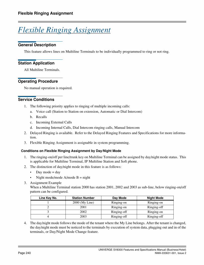
UNIVERGE SV8300 Features and Specifications Manual (Business/Hotel)Page 240 NWA-033631-001, Issue 2
Flexible Ringing Assignment
Flexible Ringing Assignment
General Description
This feature allows lines on Multiline Terminals to be individually programmed to ring or not ring.
Station Application
All Multiline Terminals.
Operating Procedure
No manual operation is required.
Service Conditions
1. The following priority applies to ringing of multiple incoming calls:
a. Voice call (Station to Station on extension, Automatic or Dial Intercom)
b. Recalls
c. Incoming External Calls
d. Incoming Internal Calls, Dial Intercom ringing calls, Manual Intercom
2. Delayed Ringing is available. Refer to the Delayed Ringing Features and Specifications for more informa-tion.
3. Flexible Ringing Assignment is assignable in system programming.
Conditions on Flexible Ringing Assignment by Day/Night Mode
1. The ringing-on/off per line/trunk key on Multiline Terminal can be assigned by day/night mode status. Thisis applicable for Multiline Terminal, IP Multiline Station and Soft phone.
2. The distinction of day/night mode in this feature is as follows:
• Day mode = day
• Night mode/mode A/mode B = night
3. Assignment ExampleWhen a Multiline Terminal station 2000 has station 2001, 2002 and 2003 as sub-line, below ringing-on/offpattern can be configured.
4. The day/night mode follows the mode of the tenant where the My Line belongs. After the tenant is changed,the day/night mode must be noticed to the terminals by execution of system data, plugging out and in of theterminals, or Day/Night Mode Change feature.
Line Key No. Station Number Day Mode Night Mode
1 2000 (My Line) Ringing-on Ringing-on
2 2001 Ringing-on Ringing-off
3 2002 Ringing-off Ringing-on
4 2003 Ringing-off Ringing-off
UNIVERGE SV8300 Features and Specifications Manual (Business/Hotel)NWA-033631-001, Issue 2 Page 241
Flexible Ringing Assignment
5. After the change of day/night mode, or execution of system data, it takes 2 to 3 minutes to complete thenotification of the day/night mode to all the terminals.
6. If day/night mode is changed while ringing a terminal, the ringing is not changed for the call. It will be ef-fective from the next call termination.
7. This feature can be operated with all the methods of Day/Night Mode Change as follows:
• Day/Night Mode Change by Attendant Console
• Day/Night Mode Change by Station Dialing
• Day/Night Mode Change by System Clock
• Centralized Day/Night Mode Change - CCIS
• Day/Night Mode Change by DISA
• Day/Night Mode Change by DSS Console
• Day/Night Mode Change by external key
8. When using this feature with Ringing Line Pickup, the target of pickup may be changed depending on theday/night mode. Only the line with setting of ringing-on can be a target of Ringing Line Pickup.
9. This feature is available for Do Not Disturb override to My Line.
10. When a call terminates the sub-line of the terminal with Do Not Disturb setting on the My Line, the ringingis disabled regardless of the setting of system data.
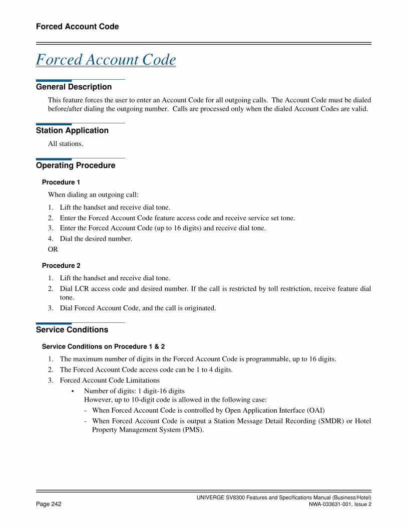
UNIVERGE SV8300 Features and Specifications Manual (Business/Hotel)Page 242 NWA-033631-001, Issue 2
Forced Account Code
Forced Account Code
General Description
This feature forces the user to enter an Account Code for all outgoing calls. The Account Code must be dialedbefore/after dialing the outgoing number. Calls are processed only when the dialed Account Codes are valid.
Station Application
All stations.
Operating Procedure
Procedure 1
When dialing an outgoing call:
1. Lift the handset and receive dial tone.
2. Enter the Forced Account Code feature access code and receive service set tone.3. Enter the Forced Account Code (up to 16 digits) and receive dial tone.
4. Dial the desired number.
OR
Procedure 2
1. Lift the handset and receive dial tone.
2. Dial LCR access code and desired number. If the call is restricted by toll restriction, receive feature dialtone.
3. Dial Forced Account Code, and the call is originated.
Service Conditions
Service Conditions on Procedure 1 & 2
1. The maximum number of digits in the Forced Account Code is programmable, up to 16 digits.
2. The Forced Account Code access code can be 1 to 4 digits.
3. Forced Account Code Limitations
• Number of digits: 1 digit-16 digitsHowever, up to 10-digit code is allowed in the following case:
- When Forced Account Code is controlled by Open Application Interface (OAI)
- When Forced Account Code is output a Station Message Detail Recording (SMDR) or HotelProperty Management System (PMS).

UNIVERGE SV8300 Features and Specifications Manual (Business/Hotel)NWA-033631-001, Issue 2 Page 243
Forced Account Code
• Number of codes: The maximum number of codes depends on the numbering scheme and digit number.The maximum number of Code Development table in the system: 3072The maximum number of codes is as follows according to the formula below*:
* 111 + (Number of digits -3) x Number of codes ≤ 3072
4. Both Authorization Code and Forced Account Code can be provided for the same system.5. Stations are assigned this feature according to Class of Service programming in system data.6. Forced Account Codes are recorded in the System Message Detail Records.7. Existing restriction assignments will be applied even after a Forced Account Code is entered. 8. If the system is designated as KF registration, this feature is not available.9. A Forced Account Code can be assigned per a station number so that one code is used only on the specific
station.
Service Conditions on Procedure 2
1. This feature can work with LCR origination (cannot work with route origination).
2. Originating terminals are Multiline Terminal, IP Multiline Terminal, SLT, and PS.
3. Feature dial tone is set at the following timing: after dialing the maximum number of digits / when time-outoccurs after dialing the number/ when dialing “#” to complete the dialing.
4. Feature dial tone is sent if the call is restricted by the toll restriction. If it is not restricted, the call is origi-nated normally.
5. This Procedure is available in the following cases:
a. During a station/trunk is placed on consultation hold
b. Outgoing call by Last Number Redial (Redial key + #)
c. Outgoing call by System Speed Dial or Station Speed Dial
d. Outgoing call by One Touch Key
6. If the toll restriction class for the calling party is higher than the one after dialing the Forced Account code,the outgoing call is restricted and the calling party will hear Reorder Tone.
7. A station under Room Cut Off, Special Dial Tone is received after the calling station will hear feature dialtone after the desired number is dialed, but the call is restricted after entering the Forced Account code andthe calling station will hear Reorder Tone.
8. Outgoing ISDN calls by Trunk Direct Appearance cannot be made by this feature.
9. When a station under toll restriction sets Call forwarding-Outside, the call to that station can not be forward-ed by this feature.
Number of digits 4 5 6 7 8 9 10 16
Number of codes 2961 1480 987 740 592 493 423 227
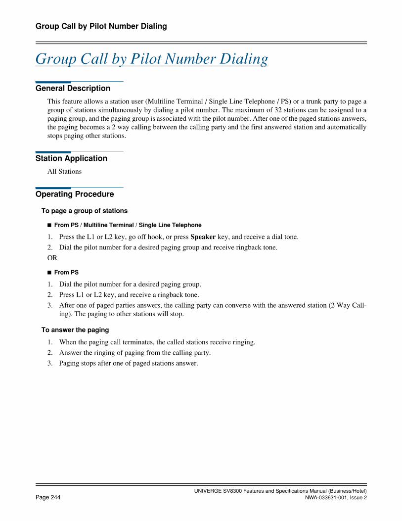
UNIVERGE SV8300 Features and Specifications Manual (Business/Hotel)Page 244 NWA-033631-001, Issue 2
Group Call by Pilot Number Dialing
Group Call by Pilot Number Dialing
General Description
This feature allows a station user (Multiline Terminal / Single Line Telephone / PS) or a trunk party to page agroup of stations simultaneously by dialing a pilot number. The maximum of 32 stations can be assigned to apaging group, and the paging group is associated with the pilot number. After one of the paged stations answers,the paging becomes a 2 way calling between the calling party and the first answered station and automaticallystops paging other stations.
Station Application
All Stations
Operating Procedure
To page a group of stations
From PS / Multiline Terminal / Single Line Telephone
1. Press the L1 or L2 key, go off hook, or press Speaker key, and receive a dial tone.
2. Dial the pilot number for a desired paging group and receive ringback tone.
OR
From PS
1. Dial the pilot number for a desired paging group.
2. Press L1 or L2 key, and receive a ringback tone.
3. After one of paged parties answers, the calling party can converse with the answered station (2 Way Call-ing). The paging to other stations will stop.
To answer the paging
1. When the paging call terminates, the called stations receive ringing.
2. Answer the ringing of paging from the calling party.
3. Paging stops after one of paged stations answer.

UNIVERGE SV8300 Features and Specifications Manual (Business/Hotel)NWA-033631-001, Issue 2 Page 245
Group Call by Pilot Number Dialing
Service Conditions
1. Example of an operating pattern is below.
Figure 1. Service Operations (when two incoming calls terminate to a same Group Call group)
a. 1st call termination to Pilot Station #3000A call to the Pilot Station #3000 will ring Stations #3101, #3102, and #3103, except busy Station#3100.
b. 2nd call termination to Pilot Station #3000During status above, a 2nd call to Pilot Station #3000 will slip to #3001 through Station Hunting -Terminal. The 2nd call does not ring, because Stations #3101 to #3103 are already rung by the 1stcall. The 2nd call will be queued.
c. Station #3101 answers the 1st callWhen Station #3101 answers the 1st call, the calling party of the 1st call and Station #3101 canconverse, and the ringing to Stations #3102 and #3103 will stop. After that, the queued 2nd call toPilot Station #3001 will start ringing to Stations #3102 and #3103.
d. Station #3102 answers the 2nd callWhen Station #3102 answers the 2nd call, the calling party of the 2nd call and Station #3102 canconverse. The ringing to Station #3103 will stop.
2. A station (Multiline Terminal, Single Line Telephone, PS) and trunk can be a calling party.Calling Party is not restricted by class of service for Group Call feature, but should be able to terminate toGroup Call pilot stations (ex. Not restricted by tenant-to-tenant connection restriction, etc.).
Conditions on Group Call pilot stations
1. A Pilot station should be assigned to a Group Call group. When a call terminated to the pilot station, stationsin the associated Group Call group will be paged simultaneously. Therefore, a dedicated station number(virtual station number) should be assigned as a pilot station.
2. One Group Call pilot station can be assigned to only one Group Call group, not multiple groups.
a. Pilot station number #3000 to #3002 are grouped in Station Hunting - Terminal group.b. Each pilot station number is assigned to the same Group Call group #00.
3000 3001 3002
3100 3101 3102 3103
(Busy)
Station Hunting – Terminal group of pilot stationsfor Group Call group #00
Group Call group #00
1st call is terminated to #3000.2nd call to #3000 is slipped to #3001 because #3000 is busy.

UNIVERGE SV8300 Features and Specifications Manual (Business/Hotel)Page 246 NWA-033631-001, Issue 2
Group Call by Pilot Number Dialing
3. Multiple pilot stations (virtual stations) associated with the same Group Call group must be assigned witha Station Hunting - Terminal group. This allows multiple calls to terminate the Group Call group simulta-neously. If Station Hunting group is not assigned during the 1st Group Call is processed, 2nd call to the pilotstation will not process the Group Call, and the calling party will hear Busy Tone.
4. Up to 32 Group Call pilot stations can be assigned per Station Hunting group. The number of stations in oneStation Hunting group should be set as the number of stations in one Group Call group. The number ofGroup Call pilot stations in the Station Hunting group will be the maximum number of calls able to termi-nate to the Group Call group at the same time. If calls exceed this number, Busy Tone will be heard.
Conditions on Group Call group and Group Call stations
1. Up to 20 Group Call groups per system can be assigned.
2. Up to 32 stations per group can be assigned (assigned stations are called “Group Call stations” hereinafter),and those stations can be called at the same time.
3. Single Line Telephones, PS (My Line and Sub Line), Multiline Terminals and virtual stations can be as-signed in a Group Call group. Attendant Consoles, ISDN Terminals and trunks cannot be assigned. One sta-tion cannot be assigned in multiple Group Call groups. No more than PS should be registered in the same group. (If registering more than 8, the call termination toPS may be delayed.) While a PS is roaming, a Group Call does not terminate to that PS.
Conditions on Paging
1. When a station in Group Call group sets Call Forwarding - All Calls or Do Not Disturb, a Group Call cannotpage the station. It is regarded as in busy status.
2. When a station in Group Call group sets Call Forwarding - Busy Line, and the station is busy, Call Forward-ing - Busy Line is not operated and a Group Call cannot page the station. It is regarded as in busy status.
3. A Group Call encounters that all stations in a Group Call group are busy (Note), a caller will hear BusyTone.
Note: Busy status means when Call Forwarding - All Calls, or Do Not Disturb is set, during conversation, ororiginating a call, but not during terminating a call.
4. When a Group Call pilot station sets Call Forwarding - All Calls or Call Forwarding - Busy Line and thepilot station is busy, a call to the pilot station will be forwarded and the Group Call is not operated. When a Group Call pilot station sets Call Forwarding - No Answer, the Group Call is activated until no-answer timeout is occurred. After no-answer timeout is occurred, the Group Call will be cancelled and thecall will be forwarded.
5. When a Group Call station sets Call Forwarding - No Answer, the Group Call will not be forwarded and theGroup Call station will be paged.
6. A Group Call will be continued until a caller hangs up. But when a call is terminated to Sub Line of PS, theringing will stop in one minute.
7. When a PS is assigned in a Group Call group, a Group Call might not be terminated to the PS depending onthe conditions of the ZT (B channels all busy), or termination might be delayed. To avoid this, Sub Line ofPS should be assigned as a Group Call station. That is because a call termination to My Line of PS occupiesone B channel and it might cause all B channels to be busy when multiple PSs are called. The call termina-tion to Sub Line of PS does not occupy B channels (after answering, one B channel is occupied.) It also doesnot affect the call termination to the PS (other than Group Call).
UNIVERGE SV8300 Features and Specifications Manual (Business/Hotel)NWA-033631-001, Issue 2 Page 247
Group Call by Pilot Number Dialing
Also, when PS is out of zone or its power is off and the PS is called using Group Call, features related toPS-Not Available are not operated. The ringing does not stop even after the programmed time.
Announcement - PS Out of Zone
Call Forwarding - Not Available (call forward to VMS)
Station Hunting - Not Available
8. Conditions on Group Call during the calling station is holding another call
• Calling Station #3000 goes on hook before the called party answersWhen Station #3000 who has Station #3500 on hold goes on hook during ringing to grouped stations,Group Call is replaced by from Station #3500 instead of Station #3000 (Blind Transfer). When the ring-ing station is a Multiline Terminal/IP Multiline Station, the caller display will change form 3000 to3500. When it is a PS, its display will remain as 3000 even after station #3000 goes on hook (due to PSlimitation). When a station (Multiline Terminal/IP Multiline Station/PS) is called after station #3000goes on hook, the caller display will be the actual caller number 3500. (Same operation when the heldparty is a trunk)
• If Blind Transfer is operated when one of grouped stations has not been called yet, it will delay the ring-ing start of the station because the call termination process is started again from the first called station.If the station that was busy at first Group Call becomes idle at this time, the station is rung. If it is stillbusy at this time, the station will not be called even if it becomes idle later.
If called parties do not answer within predetermined time, it stops ringing Group Call and Call Backis made from Station #3500 to the original calling Station #3000.
9. Group Call from trunk is available in following termination.
a. Direct Inward Termination (DIT)
b. Direct Inward Dialing (DID)
c. Automated Attendant
d. DID (ISDN)
e. Incoming Tie Line calls (destination station is designated by LCR.)
10. Group Call calls up stations in the group sequentially (in 80 ms period) only once as shown in Other Con-ditions 4. When the station in the group is not idle in that period, the Group Call is not operated at that sta-tion. Also, when that station changes to idle status while Group Call is operated in that group, Group Callis not operated at that station.
Other Conditions
1. In Calling Number Display feature, when a caller of Group Call is Multiline Terminal, the answered stationnumber will be displayed. When a caller is PS, the answered station number is not displayed.
2. When a caller is CCIS trunk, the answered station number is sent to the calling CCIS trunk. Only CCIStrunks are allowed to indicate.
3. According to the order of system data (Registration of Group Call Stations), call up one station sequentially(80 ms). But when PS, a few seconds might need till termination, so they do not always ring in order. Also,allot top station per termination. Allotment is operated per group. See following example.
Example) Group Call group #00
1st 2nd
00 Station #200
01 Station #201
02 Station #202

UNIVERGE SV8300 Features and Specifications Manual (Business/Hotel)Page 248 NWA-033631-001, Issue 2
Group Call by Pilot Number Dialing
03 Station #203
case above,
1st termination: #200 → #201 → #202 → #203
2nd termination: #201 → #202 → #203 → #200
3rd termination: #202 → #203 → #200 → #201
4th termination: #203 → #200 → #201 → #202
5th termination: #200 → #201 → #202 → #203
4. When a calling station of a Group Call is registered in that Group Call group, the calling station cannot becalled because it is regarded as in busy status.
5. When Group Call group A and B are assigned and the pilot station of group A has set Call Forwarding –All Calls to the pilot station of group B, if the pilot station of group A is called, group A will not be calledand group B will be called.
6. When Group Call group A and B are assigned and the pilot stations of group A and B has set Station Huntinggroup, if the pilot station of group A is called during busy state, group A will not be called and group B willbe called.
7. When Group Call group A and B are assigned and the pilot station of group A has set Call Forwarding –NoAnswer to the pilot station of group B, if the Call Forwarding of the pilot station of group A is activated,only the pilot station of group B will be called. Group Call to group B will not be operated.

UNIVERGE SV8300 Features and Specifications Manual (Business/Hotel)NWA-033631-001, Issue 2 Page 249
Group Listening
Group Listening
General Description
When a Multiline Terminal user makes a call using the handset, pressing the Speaker key will allow others tolisten through the built-in speaker of the Multiline Terminal. The user may continue talking on the handset atthe same time.
Station Application
All Multiline Terminals.
Operating Procedure
To monitor a call
1. Talk with a station/trunk by handset.
2. Press the Speaker key and the associated LED lights.
3. Continue the conversation on the handset.
4. To return to private conversation, press the Speaker key again.
Service Conditions
1. This feature applies to both internal and external calls.
2. Volume may be adjusted using the Multiline Terminal's volume control.
3. Group Listening is assigned in Class of Service on a per station basis.

UNIVERGE SV8300 Features and Specifications Manual (Business/Hotel)Page 250 NWA-033631-001, Issue 2
Handsfree Answerback
Handsfree Answerback
General Description
This feature allows the station user to answer a voice call without lifting the handset.
Station Application
All Multiline Terminals.
Operating Procedure
To answer a voice call
1. Make sure the MIC (Microphone) is active and the associated LED is lit.
2. Respond to call handsfree.
Service Conditions
1. Handsfree Answerback may only be used when responding to calls on the primary extension.
2. The MIC LED on the Multiline Terminal must be lit before Handsfree Answerback can begin.
3. The MIC is turned on and off by pressing the Feature key followed by the digit 1 (one).
UNIVERGE SV8300 Features and Specifications Manual (Business/Hotel)NWA-033631-001, Issue 2 Page 251
Handsfree Dialing and Monitoring
Handsfree Dialing and Monitoring
General Description
This feature allows the station user to dial or monitor a call without lifting the handset.
Station Application
All Multiline Terminals.
Operating Procedure
To initiate a call
1. Press the Speaker key and receive dial tone.
2. Dial the desired number.
3. When the called party answers, lift the handset.
To monitor a call
1. Press the Speaker key and replace the handset.
2. When the conversation resumes, lift the handset.
Service Conditions
1. This feature may be used for both internal and external calls.
2. Volume may be adjusted using the speaker volume control on the Multiline Terminal.
3. To talk to the called party, the user may use the handset, or may talk handsfree if the MIC is active.
UNIVERGE SV8300 Features and Specifications Manual (Business/Hotel)Page 252 NWA-033631-001, Issue 2
HoldAutomatic Hold
Hold
General Description
This feature permits a user to Hold a call in progress. After Hold has been set, the station user can make oranswer new calls.
Automatic Hold
General Description
This feature allows a Multiline Terminal user to automatically hold a call in progress when other line/trunk keyis pressed.
Station Application
All Multiline Terminals.
Operating Procedure
While a call in progress:
1. Press other line/trunk key on the Multiline Terminal. The line/trunk key is seized and the call in progressis automatically placed on hold.
2. The Multiline Terminal user now can make a new call or answer a ringing call on that line/trunk key.
Service Conditions
1. This feature can be allowed or denied on a individual station basis by system data programming.

UNIVERGE SV8300 Features and Specifications Manual (Business/Hotel)NWA-033631-001, Issue 2 Page 253
HoldCall Hold
Call Hold
General Description
This feature permits a user to Hold a call in progress by sending a hookflash and dialing the Call Hold featureaccess code, or by pressing the Call Hold key. This line can then be used for originating another call or returningto a previously held call.
Station Application
All stations.
Operating Procedure
To Hold a call in progress
From a Single Line Telephone
1. Press the FLASH key (or momentarily press the hookswitch) and receive special dial tone.
2. Dial the Call Hold feature access code and receive dial tone.
3. The call in progress is held and the station may make a new call.
From a Multiline Terminal with a Call Hold key assigned
1. Press the CALL HOLD key and receive dial tone.
2. The call in progress is held and the user may make a new call.
From a Multiline Terminal without a Call Hold key
1. Press the Transfer key and receive special dial tone.
2. Dial the Call Hold feature access code and receive dial tone.
3. The call in progress is held and the user may make a new call.
To release a call and return to the original call
From a Single Line Telephone
1. Hang up to release the call in progress.
2. The original call rings back to station.
3. Lift the handset and continue with the original call.
From a Multiline Terminal
1. Go on-hook to release the call in progress.
2. The original call rings back to Multiline Terminal.
3. Lift the handset and continue with the original call.
To Hold a call and return to the original call
From a Single Line Telephone
UNIVERGE SV8300 Features and Specifications Manual (Business/Hotel)Page 254 NWA-033631-001, Issue 2
HoldCall Hold
1. Press the FLASH key (or momentarily press the hookswitch) and receive special dial tone.
2. Dial the Call Hold feature access code. The call is now on Hold.
3. The original call is automatically returned.
From a Multiline Terminal
1. Press the Transfer key and receive special dial tone.
2. Dial the Call Hold feature access code. The new call is now held and the original call is automatically re-turned.
Note: By repeating the above steps, the station users may alternately converse with two parties (Broker's Call).
From a Multiline Terminal with a call in Call Hold and a call in progress on an extension line key
1. Replacing the handset will release the call in progress and initiate an immediate recall of the Call Hold call.
2. Pressing the Recall key will release the call in progress. The terminal immediately connects to new DialTone unless the call in progress on the extension line key is via a trunk programmed as Centrex; in this casethe Recall key generates a hookflash to the distant exchange for feature access there.
Service Conditions
1. Lines freed through use of this feature may also be used for answering incoming calls using the Call PickupGroup or Trunk Answer any Station features.
2. If the controlling station user does not dial any further digits after the Hold feature access code, the stationwill enter the Line Lockout mode after a preset time-out period.
3. Calls will remain on Hold until the controlling station user either replaces the handset, causing the held callto ring back, or provides a hookflash and dials the Hold feature access code again to return to the originalcall.
4. Only one call at a time may be held per station line, and the held call cannot be added to another call as inthree-party Conference.
5. Stations may be allowed or denied this feature in Class of Service programming in station data.
6. A maximum of 128 stations per system may simultaneously use this feature.
7. When a station has a Camp-On call, providing a hookflash and dialing the Call Hold feature access coderesults in the station immediately connecting to the Camped-On party.

UNIVERGE SV8300 Features and Specifications Manual (Business/Hotel)NWA-033631-001, Issue 2 Page 255
HoldDual Hold
Dual Hold
General Description
This feature permits a station user who is placed on Hold by another station to place that station on Hold also.
Station Application
All Multiline Terminals.
Operating Procedure
Internal party connection from a Multiline Terminal:
1. Station A presses the Hold key and Station B is placed on hold.
2. Station B presses the Hold key and Station A is placed on hold.
3. Dual Hold is now in progress.
Service Conditions
1. The party who placed the other party on Hold first will not receive a recall until the other party releases theDual Hold.
2. This feature is available for extension calls including Intercom calls.
3. When two Multiline Terminals activate this feature, the recall timer begins when the second station goes onHold (the first hold is no longer timed). When the timer expires, the second station is recalled and uponanswering initiates a recall to the first station.
4. An Intercom Voice Call with Hands free Answerback cannot be placed on Hold. The called party must beoff-hook using the terminal's handset in order for this call to be placed on Hold.

UNIVERGE SV8300 Features and Specifications Manual (Business/Hotel)Page 256 NWA-033631-001, Issue 2
HoldExclusive Hold
Exclusive Hold
General Description
This feature allows a Multiline Terminal user to place a call on Hold and to exclude all other station users fromretrieving the held call.
Station Application
All Multiline Terminals.
Operating Procedure
While a call is in progress:
1. Press the Transfer key and then press the Hold key. The LCD displays: E-HOLD
OR
2. Press the Hold key twice. The LCD displays: E-HOLD
3. To return to the held call, press the held line key. The conversation is re-established.
Service Conditions
1. Exclusive Hold may be activated from any line appearing on a Multiline Terminal.
2. After Exclusive Hold has been set, the user can make or answer calls from any other line appearing on theMultiline Terminal.
3. Only the Multiline Terminal that set Exclusive Hold may retrieve the held call.
4. The station initiating the Exclusive Hold will receive a distinctive I-Hold indication.
5. After a programmable period of time, the held call will be automatically recalled regardless of the status ofthe Multiline Terminal. Ringing, however, is disabled while Do Not Disturb is activated.
6. The LEDs of other Multiline Terminals on which the held line appears will give a steady display while theExclusive Hold exists and during recall.
7. An internal station on Exclusive Hold cannot receive the following:
• Camp-On
• Attendant Override
• Executive Override

UNIVERGE SV8300 Features and Specifications Manual (Business/Hotel)NWA-033631-001, Issue 2 Page 257
HoldNon-exclusive Hold
Non-exclusive Hold
General Description
This feature allows a Multiline Terminal user to place a call on Hold that may be retrieved by any station thathas an appearance of the held line.
Station Application
All Multiline Terminals.
Operating Procedure
1. With a call in progress, press the Hold key (once).
2. To retrieve a held call, press the held line key.
Service Conditions
1. Any Multiline Terminal displaying another appearance of the held line can seize the held call.
2. Automatic Recall is directed only to the station that placed the call on Hold.
3. The station initiating Hold will receive a distinctive I-Hold indication.
4. Two-Party Hold is available when a Multiline Terminal is engaged in a three-party Conference with stationsand/or trunks.
5. When two parties are put on Hold, service features such as Executive Override, Attendant Override, andCamp-On cannot be activated to that busy line with the two parties on Hold.
6. The two held parties remain connected to each other and can talk to each other. Music on Hold is not acti-vated.
7. The two held parties cannot be placed on Exclusive Hold by the Multiline Terminal user.
8. If one of the two held parties is released from the connection, Music On Hold will be activated on the re-maining connection. When the holding party returns to the connection, a two-party connection is estab-lished.

UNIVERGE SV8300 Features and Specifications Manual (Business/Hotel)Page 258 NWA-033631-001, Issue 2
October, 2008
Hotel/Motel Attendant Console
Hotel/Motel Attendant Console
General Description
The Attendant Console can be programmed to function as a Hotel/Motel Attendant Console. In addition to thebusiness features and functions of the Attendant, the Hotel/Motel Attendant Console can set Room Cutoff (in-dividual and group), Automatic Wake Up, Message Waiting, and Do Not Disturb (individual and group).
Station Application
Attendant Consoles.
Operating Procedure
Room Cutoff (individual), Do Not Disturb (individual) and Message Waiting
To set
1. Dial the desired extension.
2. Press the applicable function key.
3. Press the START key.
To cancel
1. Dial the desired extension.
2. Press the applicable function key.
3. Press the RESET key.
Room Cutoff (group) and Do Not Disturb (group)
To set
1. Press the applicable function key.
2. Press the START key.
To cancel
1. Press the applicable function key.
2. Press the RESET key.
Automatic Wake Up
To set
1. Dial the desired extension.
2. Press the Automatic Wake Up function key.
3. Use military time format to dial the digits applicable to the requested Automatic Wake Up time (ex. 7:30pmis 1930).
4. Press the START key.
UNIVERGE SV8300 Features and Specifications Manual (Business/Hotel)NWA-033631-001, Issue 2 Page 259
October, 2008
Hotel/Motel Attendant Console
To cancel
1. Dial the desired extension.
2. Press the Automatic Wake Up function key.
3. Press the RESET key.
Service Conditions
1. A dedicated function key on the console must be assigned for each desired feature (Room Cutoff, AutomaticWakeup, etc.).
2. The Room Cutoff and Do Not Disturb features are applicable to a group of stations and individual stations.One group is available for each feature and the stations in the groups are programmed on a per station basisin system data.
3. Pressing the DDOVR key, when calling a station that has DND set, will override the DND setting.

UNIVERGE SV8300 Features and Specifications Manual (Business/Hotel)Page 260 NWA-033631-001, Issue 2
Hotel/Motel DID Number Allocation to Guest Station
Hotel/Motel DID Number Allocation to Guest Sta-tion
General Description
This feature allows a Property Management System (PMS) to assign a DID number for a guest station. Withthis feature, the guest station can directly receive incoming calls from the public network without attendant as-sistance. This feature is applicable for PMS interface on IP only.
Station Application
All guest stations.
Operating Procedure
Operating procedures will vary with the locally-provided PMS.
Service Conditions
1. The DID number assigned to one guest station. If another DID number is assigned to the guest station mustbe managed on the PMS side.
2. One DID number can be assigned to one guest station. If another DID number is assigned to the station, thenewly assigned number will be valid. In addition, if the DID number that has been used is assigned to an-other station, the DID call to the old station will not be valid and the call to the newly assigned station willbe valid.
3. Maximum 8 digits of DID number can be assigned for a guest station.
4. If the PMS sends a request message for DID number allocation without a guest station number, the desti-nation for that DID number is followed by system data programming.
5. The destination of the DID call by this feature cannot be changed by day/night/mode A/B/mode.
6. A guest station in Do Not Disturb cannot be called by the DID call.

UNIVERGE SV8300 Features and Specifications Manual (Business/Hotel)NWA-033631-001, Issue 2 Page 261
Hotel/Motel Front Desk Instrument
Hotel/Motel Front Desk Instrument
General Description
A Multiline Terminal with LCD can be programmed to function as a Hotel/Motel (H/M) Front Desk Instrument.This can be used to set and cancel standard H/M features such as Message Waiting, Do Not Disturb, AutomaticWake Up, and Room Cutoff.
Station Application
All Multiline Terminals with LCD.
Operating Procedure
Normal call processing procedures apply except for the following:
• When calling a station that has set Do Not Disturb (DND), pressing the DNDOVR key will override the DND condition.
To activate Do Not Disturb, Message Waiting, and Room Cutoff
1. Press the applicable function button.
2. Dial the desired station number where feature is to be set or canceled. (This procedure is not required whenspeaking with that station in a Station-to-Station call or when setting the group functions.)
3. Press the SET key to set the desired function.
OR
Press the RESET key to cancel the desired function.
4. Repeat the above steps if multiple station assignments are desired.
OR
Press the RLS key to exit feature activation.Note: For alternate operating procedures, refer to the applicable feature.
To activate Do Not Disturb (group) or Room Cutoff (group)
1. Press the DD or RC key.
2. Press the GROUP key.
3. Press the SET key.
4. Press the RLS key.
To cancel Do Not Disturb (group) or Room Cutoff (group)
1. Press the DD or RC key.
2. Press the GROUP key.
3. Press the SET key.
4. Press the RLS key.
UNIVERGE SV8300 Features and Specifications Manual (Business/Hotel)Page 262 NWA-033631-001, Issue 2
Hotel/Motel Front Desk Instrument
To activate Automatic Wake Up
1. Press the WK UP key.
2. Dial the desired Wake-Up time in military format (in one minute increments).
3. Press the WK UP key.
4. Dial the station number.
5. Press the SET key.
Steps (4) and (5) can be repeated for additional stations.
6. Press the RLS key.
OR
1. Press the WK UP key.
2. Dial the station number.
3. Press the SET key.
4. Dial the desired wake up time in military format (in one minute increments).
5. Press the SET key.
Steps (2) through (5) can be repeated for additional stations.
6. Press the RLS key.
To cancel Automatic Wake Up
1. Press WK UP key.
2. Dial station number.
3. Press RESET key.
Steps (2) and (3) can be repeated for additional stations.
4. Press RLS key.
To activate Automatic Wake Up while engaged in conversation with station
1. Press the WK UP key.
2. Dial the Wake up time in military format (in one minute increments).
3. Press the SET key.
4. Press the RLS key.
To cancel Automatic Wake Up while engaged in conversation with station
1. Press the WK UP key.
2. Press the RESET key.
3. Press the RLS key.
To activate Check In/Check Out
1. Press the Check In/Check Out function button.
2. Dial the desired station number.
3. Press the SET key to set Check In.
OR
Press the RESET key to set Check Out.

UNIVERGE SV8300 Features and Specifications Manual (Business/Hotel)NWA-033631-001, Issue 2 Page 263
Hotel/Motel Front Desk Instrument
To activate Room Status
1. Press the Room Status function button.
2. Dial the desired station number.
3. Press the SET key. The features that are activated at the station will be indicated by the LED lighting at theapplicable feature function button and the LCD will display **:** unless Automatic Wake Up is set, inwhich case the set time will be displayed. In addition (to the right of the display) the Room Status numberis displayed.
4. Press the RLS key to exit feature activation.
To activate Print Out
1. Press the Print Out function button.
2. Press the applicable function button for which a Print Out is desired. If Room Status is selected, a codemust be dialed to select which room condition is to be printed. If a code is not entered all room conditionswill be printed.
3. Press the SET key.
4. Press the RLS key to exit feature activation.
Service Conditions
1. The following Hotel/Motel functions can be accessed from the Hotel/Motel Front Desk Instrument:
• Automatic Wake Up
• Check In/Check Out Note
• Do Not Disturb
• Do Not Disturb-Override
• Message Waiting
• Room Cutoff
• Room Status Note
• Hotel/Motel Toll Restriction change-Guest StationNote: When CPU built-in PMS on IP is provides, you can set and cancel these hotel features only from PMS
• Check In/Check Out• Room Status
2. For each feature desired, a dedicated line key on the Hotel/Motel Front Desk Instrument must be assigned.
3. The Room Cutoff and Do Not Disturb features are applicable to a group of stations and individual stations.There is one group available for each feature and the stations in the groups are programmed on a per-stationbasis in system data.
4. When Check Out is done, the following functions are set or cleared:
• DND - cleared
• Message Wait - cleared
• Room Cutoff - set
• Automatic Wake Up - cleared
5. Room Status Codes are totally flexible, and the user determines the meaning for each code. The system willprint the maid ID or station number (if other than guest room) that set the specific code. Up to eight codes(1-8) are available.
UNIVERGE SV8300 Features and Specifications Manual (Business/Hotel)Page 264 NWA-033631-001, Issue 2
Hotel/Motel Front Desk Instrument
Service Conditions on Printer connection
1. The Print Out function provides a hard copy the status of following features when the feature is set or reset:
- Automatic Wake Up
- Check In/Check Out
- Do Not Disturb
- Message Waiting
- Room Cutoff
- Room Status Code Change
2. Successful and unsuccessful Wake Up attempts are printed out.
3. A printer must be provided locally.
4. The Print Out function allows selection of output based on individual station numbers (except for RoomStatus).
Service Conditions on Built-in PMS on IP
1. When the Built-in PMS on IP is used, below information regarding Hotel/Motel service can be automati-cally output to a Hotel/Motel Printer connected to an RS port of an CPU balde
• Automatic Wake-Up Set/Cancel
• Automatic Wake-Up Result
• Do Not Disturb Set/Cancel
• Message Waiting Set/Cancel
• Room Cutoff Set/Cancel
• Maid Status Change Result
• Immediate Printout of Call Detailed Record

UNIVERGE SV8300 Features and Specifications Manual (Business/Hotel)NWA-033631-001, Issue 2 Page 265
Hotel/Motel Toll Restriction Change - Guest Station
Hotel/Motel Toll Restriction Change - Guest Station
General Description
This feature allows the Hotel/Motel Front Desk Instrument to set a trunk restriction class of each guest stationby Room Status code change (For example, Guest-A: all outgoing calls are allowed, Guest-B: only local callsare allowed).
Station Application
Digital Multiline Terminals with LCD assigned as Hotel/Motel Front Desk Instruments.
Operating Procedure
To change Room Status Code (Trunk Restriction Class) from the Hotel/Motel Front Desk Instrument
1. Press the STS key.
2. Dial the guest station number.
3. Press the SET key - Room Status is displayed.
4. Press the STS key again.
5. Dial the desired Room Status code (from 1 to 8).
6. Press the SET key. Repeat Procedure 2~5 for other stations.
7. Press the RLS key.
Service Conditions
1. This feature is available only for the system without PMS Interface.
2. A trunk restriction class can be set per guest station. 3. The system provides up to eight types of trunk restriction classes.4. The trunk restriction class must be assigned to each Room Status code by system programming. The same
trunk restriction class can be assigned to the different Room Status codes.5. Following are examples of the system operations with this feature.
Example 1
• Guest type
- Guest A: All outgoing calls are allowed
- Guest B: Only local calls are allowed
Most of the guests are Guest A, and some are Guest B.
• Trunk Restriction Class assignment
- Restriction Class A: All outgoing calls are allowed.
- Restriction Class B: Only local calls are allowed.
Assign default restriction class of the guest stations to Restriction Class A.

UNIVERGE SV8300 Features and Specifications Manual (Business/Hotel)Page 266 NWA-033631-001, Issue 2
Hotel/Motel Toll Restriction Change - Guest Station
• Room Status Code assignment
• Check In operation
- Room Status Code of the guest station is automatically set to “1” (all outgoing calls are allowed).
- For Guest B, after the Check In operation, change the Room Status Code to “2” from the Hotel/MotelFront Desk Instrument, to set the trunk restriction class to “B” (only local calls are allowed).
• Check Out operation
- Room Status code of the guest station is automatically set to “3” (all outgoing calls are restricted).
Example 2
• Guest type
- Guest A: All outgoing calls are allowed
- Guest B: Only local calls are allowed
A local call is free of charge.
• Trunk Restriction Class assignment
- Restriction Class A: All outgoing calls are allowed.
- Restriction Class B: Only local calls are allowed.
Assign default restriction class of the guest stations to Restriction Class B.
• Room Status Code assignmentt
• Check In operation
- Room Status Code of the guest station is automatically set to “1” (only local calls are allowed).
- For Guest A, after the Check In operation, change the Room Status Code to “2” from the Hotel/MotelFront Desk Instrument, to set the trunk restriction class to “A” (all outgoing calls are allowed).
• Check Out operation
- Room Status code of the guest station is automatically set to “3” (only local calls are allowed).
Room Status Code Room Status Room Cutoff Trunk Restriction Class
1 Check In (Guest A) Reset A
2 Check In (Guest B) Reset B
3 Check Out Set A
Room Status Code Room Status Room Cutoff Trunk Restriction Class
1 Check In (Guest B) Reset B
2 Check In (Guest A) Reset A
3 Check Out Reset B
UNIVERGE SV8300 Features and Specifications Manual (Business/Hotel)NWA-033631-001, Issue 2 Page 267
Hotline - Inside/Outside
Hotline - Inside/Outside
General Description
This feature causes the terminal to place a call to another station or to an outside party automatically when theuser selects the Hotline extension.
Station Application
All stations.
Operating Procedure
To place a Hotline call from a Single Line Telephone
1. Lift the handset and receive ringback tone. The other party receives ringing indication.
2. Converse when the other party answers.
To place a Hotline call from a Multiline Terminal
1. Lift the handset.
2. Press the Hotline extension button (if not Prime Line). Receive ringback tone. The other party receivesringing indication.
3. Converse when the other party answers.
Service Conditions
1. There is a maximum of 100 assignments for Hotline destination. If internal bidirectional Hotline calling isrequired, two assignments (one for each direction) must be made. A maximum of 50 pairs of bidirectionalHotlines can be assigned.
2. Hotline assignments are programmed into system data using the PCPro or Customer Administration Ter-minal (CAT).
3. A Hotline call can be transferred to another station using the Call Transfer feature.4. On an internal Hotline call, the calling party hears reorder tone when the called station is in one of the fol-
lowing conditions:• Busy• In Line Lockout• In make busy through software programming.
5. Call Forwarding is applied whenever the destination station of the Hotline call has set Call Forwarding -AllCalls/-Busy Line/-No Answer.
6. Hotline calls can be directed to the outside exchange network by assignment of the destination as a systemspeed dial memory location. When this Hotline is used, the system will access a trunk in the trunk routeassociated with the trunk access code assigned in the system speed dial memory location, and then will dialout the assigned outside number. See System Speed Dialing for the methods to reprogram the outside num-ber.
7. On Hotline - Outside calls, when all trunks in the trunk route are busy, reorder tone is heard by the callingparty.
UNIVERGE SV8300 Features and Specifications Manual (Business/Hotel)Page 268 NWA-033631-001, Issue 2
Hotline - Inside/Outside
8. On Hotline - Outside calls, Station Message Detail Recording (SMDR) will register the primary extensionof the station that used the Hotline and the system speed dial memory location code.
UNIVERGE SV8300 Features and Specifications Manual (Business/Hotel)NWA-033631-001, Issue 2 Page 269
House Phone
House Phone
General Description
This feature allows selected stations to reach the Attendant simply by going off-hook.
Station Application
All stations.
Operating Procedure
1. The House Phone user lifts handset.
2. The Attendant Console is called automatically.
3. The attendant answers.
4. The attendant connects the user to another station or a trunk.
Service Conditions
1. Attendant Console indications will appear as follows:
• ATND lamp flashes.
• Console buzzer sounds.
2. House Phones (locally provided) may be equipped without dials .
3. House Phone assignments are programmed into system data from the PCPro or the Customer Administra-tion Terminal (CAT).
4. There is no limit to the number of House Phones permitted in the system provided the maximum numberof available ports is not exceeded.
5. The Attendant has the option to process the call using the delay or non-delay operation or passing dial toneto House Phones with dials.
6. The system's response to a hookflash from a House Phone can be assigned to provide feature dial tone orcall the Attendant again.
7. Four house phone groups are available.
8. Each house phone group can be assigned to automatically call the Attendant Console or a designated station.
UNIVERGE SV8300 Features and Specifications Manual (Business/Hotel)Page 270 NWA-033631-001, Issue 2
Intercept Announcement
Intercept Announcement
General Description
This feature provides the automatic interception of Direct Inward Dialing (DID) and Tie Line calls that cannotbe completed due to unassigned station or level. The caller hears a recorded Intercept Announcement that in-forms the caller that an inoperative number was reached, and may supply the number for information.
Station Application
Not applicable.
Operating Procedure
To record a message
1. Go off-hook and receive internal dial tone.
2. Dial the voice recording feature access code and the voice recording card number. Three seconds of tonewill be supplied.
3. Record the message (maximum duration 30 seconds).
4. Restore the handset.
Service Conditions
1. An Intercept Announcement can be recorded on a Voice Response System (VRS). The maximum durationfor a message is 30 seconds. The message is stored on an internal memory of the CPU blade in Unit #1(CPU #1).
2. Multiple calls may be connected to the Intercept Announcement board at the same time. If a second callarrives while the first is being processed, the second caller may not hear the announcement from the begin-ning.
3. If the caller does not hang up, the system will repeat the message.
4. This feature is only available on DID and tie line calls where answer supervision is provided.
5. The following call conditions, which cannot be completed, can be routed to an Intercept Announcement:
• vacant level.
• unassigned station number.
6. Calls to restricted access codes or feature access codes will always receive the Intercept Announcement.
7. Only one common message can be provided for the different intercept conditions.
8. There is no method to exempt individual DID or Tie Lines from Intercept Announcement.

UNIVERGE SV8300 Features and Specifications Manual (Business/Hotel)NWA-033631-001, Issue 2 Page 271
October, 2008
IntercomManual Intercom
Intercom
General Description
Three types of Intercoms are available: Manual Intercom, Automatic Intercom, and Dial Intercom. Each typeof Intercom provides access to a small group of Multiline Terminals with simplified calling methods.
Manual Intercom
General Description
The Manual Intercom groups have up to six Multiline Terminals sharing a common signal path. Users can callother members of the Manual Intercom group by pressing a Manual Intercom key; each press sends a tone burstover the speakers of all the terminals in the group. When another user answers the call, a speech path is acti-vated.
Station Application
All Multiline Terminals.
Operating Procedure
1. The caller lifts the handset and presses the Manual Intercom key. The other members of the group receivea tone burst.
2. Each subsequent press sends another tone burst.
3. Another user presses the same Manual Intercom appearance and establishes a station-to-station call by lift-ing the handset.
Service Conditions
1. A Manual Intercom group can consist of two to six Multiline Terminals.
2. A maximum of 25 Manual Intercom groups can be assigned per system.
3. A Manual Intercom is always non-private; therefore, up to 4 members of the group can enter an Intercomcall.
4. Incoming call indications are given to all members of the Manual Intercom group except the originator ofthe call.
5. Each Manual Intercom (from 2 to 6 appearances) uses a single extension that can be a software extension(no supporting hardware is required).
6. Transfer, Call Park, and other extension line features are not available on Manual Intercom. Dual Hold andHold Recall are available on Manual Intercom.
7. More than one Manual Intercom can appear on a Multiline Terminal.
8. When all members of group are busy, the caller will receive busy tone.
UNIVERGE SV8300 Features and Specifications Manual (Business/Hotel)Page 272 NWA-033631-001, Issue 2
IntercomAutomatic Intercom
Automatic Intercom
General Description
Automatic Intercom provides a path for Voice Announcement Calls with Handsfree Answerback between twoMultiline Terminals using a line key. Private conversations can be held by using the Multiline Terminal hand-sets. The Busy/Idle status of the associated Multiline Terminal is displayed on the Automatic Intercom line keyLED.
Station Application
All Multiline Terminals.
Operating Procedure
1. The caller lifts the handset and presses the Automatic Intercom key.
2. The called terminal receives a tone burst followed by Voice Announcement and can answer using Hands-free Answerback.
OR
1. The caller can change the call to a ringing call by dialing 1.
2. The called terminal must press Automatic Intercom key and lift the handset to answer ringing call.
Service Conditions
1. Only two Multiline Terminals can share an Automatic Intercom path.
2. The maximum number of Automatic Intercom paired stations per system is 32.
3. More than one Automatic Intercom can appear on a Multiline Terminal.
4. Automatic Intercoms are private.
5. Each Automatic Intercom pair uses two extensions that can be software extensions (no supporting hardwareis required).
6. Dual Hold with hold recall is available on Automatic Intercom. Other extension features such as Call Trans-fer, Call Park, etc. are not available.
7. When the called terminal is busy, the caller will receive busy tone.
UNIVERGE SV8300 Features and Specifications Manual (Business/Hotel)NWA-033631-001, Issue 2 Page 273
IntercomDial Intercom
Dial Intercom
General Description
Dial Intercom comprises up to 10 Multiline Terminals that can call each other using a dedicated Dial Intercomline key with abbreviated dialing. Dial Intercom calls can be Voice Announce with Handsfree Answerback orringing calls.
Station Application
All Multiline Terminals.
Operating Procedure
1. The caller lifts the handset, presses the Dial Intercom key, and receives dial tone.
2. The caller dials the one-digit Intercom code of the called Multiline Terminal (0-9).
3. The called terminal receives a tone burst followed by Voice Announcement and can answer using Hands-free Answerback.
OR
1. The caller can dial 1 to change the call to a ringing call. (Each 1 dialed changes the mode from ringing toVoice Announce or vice versa).
2. To answer a ringing call, the user must lift the handset and press the flashing Dial Intercom key.
Service Conditions
1. A maximum of 25 Dial Intercom groups is available per system. A maximum of 10 Multiline Terminalsper Dial Intercom group is allowed.
2. A Multiline Terminal can have more than one Dial Intercom appearance.
3. Each Dial Intercom provides a single voice path.
4. Intercom number assignments are one digit (0-9).
5. A Dial Intercom is private, and the other members of the group cannot enter an Intercom call.
6. Incoming call indication is only given to the called party within the Dial Intercom group.
7. Each Dial Intercom (from 2 to 10 appearances) uses a single extension, which can be a software extension(no supporting hardware is required).
8. Dual Hold and hold recall are available on Dial Intercom. Other extension features such as Call Transfer,Call Park, etc. are not available.
9. If the called party, within the Dial Intercom group, is busy (off hook) on its primary extension, the stationmaking the intercom call will receive busy tone.

UNIVERGE SV8300 Features and Specifications Manual (Business/Hotel)Page 274 NWA-033631-001, Issue 2
Internal Tone/Voice Signaling
Internal Tone/Voice Signaling
General Description
Multiline Terminals can signal incoming internal calls by Voice Announcement or by ringing according to theprogrammed mode (Voice first or Ring first) of the called terminal. The caller can dial the digit 1 to changefrom Voice Announcement to Ring Tone or vice versa.
The Multiline Terminal to which this feature is assigned can program the following two modes:
• Voice Mode: allows an incoming call to terminate with Voice Announcement.• Tone Mode: allows an incoming call to terminate with ringing.
Station Application
All Multiline Terminals.
Operating Procedure
When a called Multiline Terminal has been set to Ring first
1. Press the extension line key and lift the handset.
2. Dial extension number. The called party's extension will ring.
3. The handset must be used for reply.
OR
Dial 1.
4. Wait for voice page alert tone.
5. Speak to the called party.
6. The called party can reply handsfree.
When a called Multiline Terminal has been set to Voice first
1. Press the extension line key and lift the handset.
2. Dial extension number. Wait for voice page alert tone.
3. Speak to the called party.
4. The called party can reply hands-free.
OR
Dial 1.
5. The called party's extension will ring.
6. The handset must be used to reply.
To set Voice/Tone mode
1. Press the Speaker key.
2. Dial the Voice/Tone Programming access code and receive feature dial tone. The LCD will show the cur-rent mode of the Multiline Terminal.
UNIVERGE SV8300 Features and Specifications Manual (Business/Hotel)NWA-033631-001, Issue 2 Page 275
Internal Tone/Voice Signaling
3. Dial any single digit (0-9). Voice mode is switched to Tone mode (or vice versa) and Service Set tone isreceived.
4. Press the Speaker key.
Service Conditions
1. When a Multiline Terminal is receiving a Voice Announcement, it cannot receive any other audible signal.
2. Single-digit feature access codes must be allowed in system programming.
3. Voice Announce service on extension lines can be allowed or denied on a system basis.
4. Microphone control (MIC) lamp must be lit for Handsfree Answerback response.
5. Refer also to the Intercom Features and Specifications.
6. Voice announcement is available only to the primary extension of the dialed station.

UNIVERGE SV8300 Features and Specifications Manual (Business/Hotel)Page 276 NWA-033631-001, Issue 2
October, 2008
Internal Zone Paging with Meet-Me
Internal Zone Paging with Meet-Me
General Description
This feature allows the Attendant Console and system users to page over the built-in speakers of the MultilineTerminals within the assigned zone or all zones in a Single Unit, Multi-Unit or Remote Network configuration.
Station Application
• for a zone paging
Paging station: All stations
Paged station: Multiline Terminals and Soft Phones
• for all-zone paging
Paging station: Single Line Telephones, Digital Multiline Terminals and Attendant Consoles
Paged station: Multiline Terminals and Soft Phones
Operating Procedure
To page from a Multiline Terminal or a Single Line Telephone
1. Lift the handset and receive extension dial tone.
2. Dial the Internal Zone Paging feature access code for the desired zone/all zones or press line key assignedfor the desired zone/all zones.
3. Page the desired party.
To page from Attendant Console
1. Press an idle LOOP key.
2. Dial the Internal Zone Paging feature access code for the desired zone/all zones.
3. Page the desired party.
To answer (Meet-Me) from a Multiline Terminal or a Single Line Telephone
1. Lift the handset and receive extension dial tone.
2. Dial the Meet-Me Answer feature access code.
3. Converse.
Service Conditions
1. The maximum number of internal paging zones is 8, zone 0 through zone 7. Up to 8 Internal zones can beaccessed simultaneously by different stations.
2. The paging station can only page to one zone at a time. For all-zone paging, the paging station can pageZone 0 through Zone 5 simultaneously.
3. The maximum number of Multiline Terminals within one zone is 16.
4. A busy Multiline Terminal will not be paged during an Internal Zone Page.

UNIVERGE SV8300 Features and Specifications Manual (Business/Hotel)NWA-033631-001, Issue 2 Page 277
October, 2008
Internal Zone Paging with Meet-Me
5. Multiline Terminals can be assigned to more than one zone.
6. Meet-Me Answer cannot be done after performing a consultation hold.
7. The paging station will not receive busy tone when all stations in the paged zone are busy.
8. The Meet-Me Answer is available for only the Internal Zone Paging (except paging by Attendant Console).
9. The Meet-Me Answer can be performed from not only the paged stations but non-paged stations as follows;• Multiline Terminal• Soft Phone• Single Line Telephone• PS
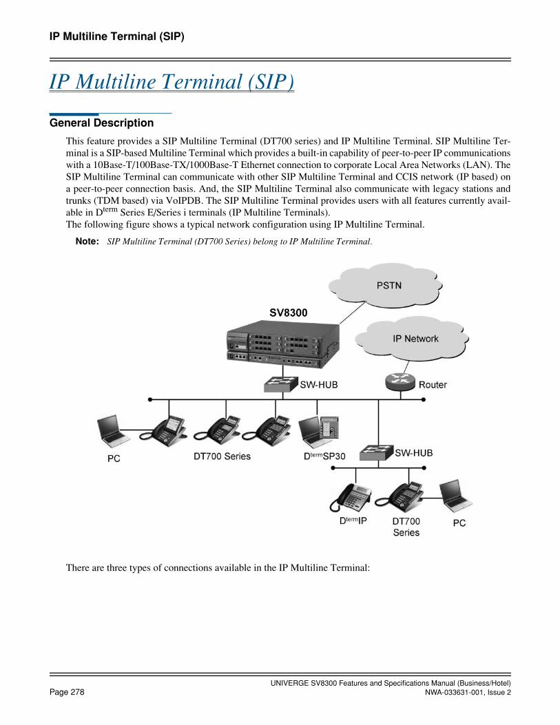
UNIVERGE SV8300 Features and Specifications Manual (Business/Hotel)Page 278 NWA-033631-001, Issue 2
IP Multiline Terminal (SIP)
IP Multiline Terminal (SIP)
General Description
This feature provides a SIP Multiline Terminal (DT700 series) and IP Multiline Terminal. SIP Multiline Ter-minal is a SIP-based Multiline Terminal which provides a built-in capability of peer-to-peer IP communicationswith a 10Base-T/100Base-TX/1000Base-T Ethernet connection to corporate Local Area Networks (LAN). TheSIP Multiline Terminal can communicate with other SIP Multiline Terminal and CCIS network (IP based) ona peer-to-peer connection basis. And, the SIP Multiline Terminal also communicate with legacy stations andtrunks (TDM based) via VoIPDB. The SIP Multiline Terminal provides users with all features currently avail-able in Dterm Series E/Series i terminals (IP Multiline Terminals).The following figure shows a typical network configuration using IP Multiline Terminal.
Note: SIP Multiline Terminal (DT700 Series) belong to IP Multiline Terminal.
There are three types of connections available in the IP Multiline Terminal:

UNIVERGE SV8300 Features and Specifications Manual (Business/Hotel)NWA-033631-001, Issue 2 Page 279
October, 2008
IP Multiline Terminal (SIP)
Peer-to-Peer Connections between IP Multiline Terminal
The IP Multiline Terminal can communicate with other IP Multiline Terminal over the LAN, on a peer-to-peerconnection basis. Call control is provided by CPU with Ethernet adapter card, and voice packets are transmittedbetween IP Multiline Terminal over the LAN (not through Time Division Switch). Voice compression ofG.729a (8 kbps), G.723.1 (5.3 kbps/6.3 kbps) and G.722 (48/56/64 kbps) is available for its connections. (G.722is available only when using DT700 series. G723.1 is not available when using DT700 series.)
Peer-to-Peer Connections over CCIS Networking via IP
The IP Multiline Terminal can communicate with other SV8300 systems over the CCIS networking via IP, ona peer-to-peer connection basis. CPU controls a connection between the IP Multiline Terminal and IP trunk builtinto the CPU. And, the built-in IP trunk communicates with IP trunks of the distant systems (SV8300) overCCIS networks via IP. Voice packets are transmitted over the LAN and WAN (via router). Voice compressionof G.729a (8 kbps), G.723.1 (5.3 kbps/6.3 kbps) and G.722 (48/56/64 kbps) is available for its connections.(G.722 is available only when using DT700 series and VoIPDB. G723.1 is not available when using DT700series and VoIPDB.)
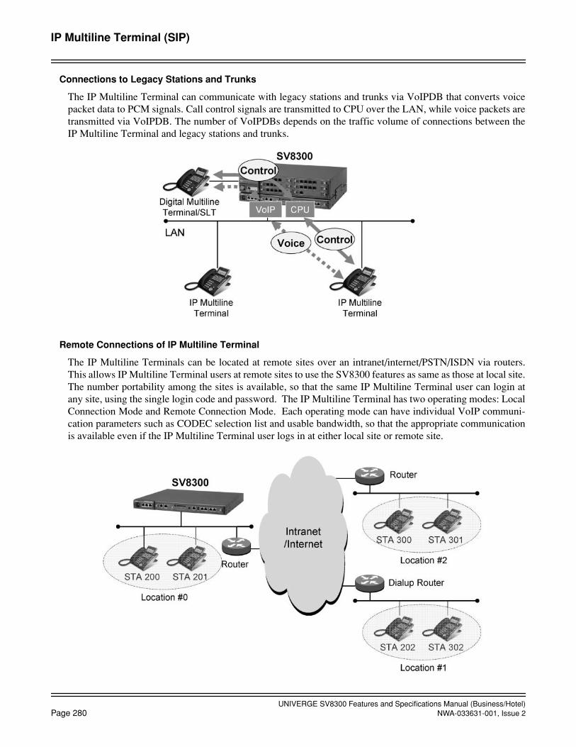
UNIVERGE SV8300 Features and Specifications Manual (Business/Hotel)Page 280 NWA-033631-001, Issue 2
IP Multiline Terminal (SIP)
Connections to Legacy Stations and Trunks
The IP Multiline Terminal can communicate with legacy stations and trunks via VoIPDB that converts voicepacket data to PCM signals. Call control signals are transmitted to CPU over the LAN, while voice packets aretransmitted via VoIPDB. The number of VoIPDBs depends on the traffic volume of connections between theIP Multiline Terminal and legacy stations and trunks.
Remote Connections of IP Multiline Terminal
The IP Multiline Terminals can be located at remote sites over an intranet/internet/PSTN/ISDN via routers.This allows IP Multiline Terminal users at remote sites to use the SV8300 features as same as those at local site.The number portability among the sites is available, so that the same IP Multiline Terminal user can login atany site, using the single login code and password. The IP Multiline Terminal has two operating modes: LocalConnection Mode and Remote Connection Mode. Each operating mode can have individual VoIP communi-cation parameters such as CODEC selection list and usable bandwidth, so that the appropriate communicationis available even if the IP Multiline Terminal user logs in at either local site or remote site.

UNIVERGE SV8300 Features and Specifications Manual (Business/Hotel)NWA-033631-001, Issue 2 Page 281
IP Multiline Terminal (SIP)
Automatic Program Download for IP Multiline Terminal
This feature provides the method to download the latest firmware program of IP Multiline Terminal from theFTP/TFTP server automatically by system programming. The following three patterns of program downloadare available.
- Program Download at Appointed Time
- Program Download for Designated Terminals
* DT700 series does not support Program Download at Login Time.

UNIVERGE SV8300 Features and Specifications Manual (Business/Hotel)Page 282 NWA-033631-001, Issue 2
IP Multiline Terminal (SIP)
Automatic Login to Home Station Number
New operation mode is added: Fixed Connection Mode. In this mode, the IP Multiline Terminal works as fol-lows.
• The IP Multiline Terminal is normally used like MAC Authentication Mode (no need to login/logout oper-ation).
• If necessary, the terminal can be temporarily logged out and can be used as someone’s own terminal by lo-gin with his/her station number and password. After he/she logged out the terminal, the terminal is auto-matically logged in to the home station number (e.g. conference room telephone).
Typical applications are as follows:
Case-1: A conference room phone is assigned as Fixed Connection Mode. Someone wants to use the confer-ence room phone temporarily as the user’s own phone. The user logs in with his/her station number (200). Afterlogout, the conference room phone can be automatically logged in to its home station number (300).
Case-2: A user has his/her desk phone (station 200) with Fixed Connection Mode. The user moves outside anoffice and he/she logs in with his/her station number (200) from his/her soft phone. At this time, his/her deskphone becomes logout status. After the user logs out his/her soft phone, his/her desk phone is automaticallylogged in to its home station number (200).

UNIVERGE SV8300 Features and Specifications Manual (Business/Hotel)NWA-033631-001, Issue 2 Page 283
IP Multiline Terminal (SIP)
Terminal Login via NAT
The SV8300 supports network configuration via a router with NAT. NAT (Network Address Translation) is atechnology that translates an internal local IP address to a globally unique IP address before sending packets tothe outside network. NAT is configured on the router at the border of the inside network and the outside net-work. NAT is used for efficient use of global IP addresses and for security (shield internal addresses from thepublic Internet).
• Remote connections of IP Multiline Station via NAT
- Provide communications between IP Multiline Station located under the same NAT.
- Provide communications between IP Multiline Station located under different NAT.

UNIVERGE SV8300 Features and Specifications Manual (Business/Hotel)Page 284 NWA-033631-001, Issue 2
October, 2008
IP Multiline Terminal (SIP)
Station Application
• SIP Multiline Terminal (DT700 series and MH240)• IP Multiline Terminal
Operating Procedure
Operating Procedure for Normal User Operations
Same as Digital Multiline Terminals.
When login mode is activated, the following display will appear.
To Login with password
1. Dial the desired station number as login code.
2. Dial the password associated with the login code. Password is displayed by “****..."
3. Press Set key. "Connecting..." is displayed in few seconds and the display changes to normal idle sta-tus, if the login code is accepted.
To Logout
1. Go off-hook or press Speaker key and receive dial tone.
2. Dial the Logout feature access code, or press the Logout feature access key or Logout Soft Key. Receiveservice set tone.
3. LCD displays the login screen.
To change the password
1. During the login status, go off-hook or press the Speaker key and receive dial tone.
2. Dial the feature access code for password change.
3. Enter the current password, new password, and the new password again. Receive service set tone, if ac-cepted. (Note 1, 2)
4. Restore the handset or press the Speaker key.Note 1: If the current password entered is wrong, reorder tone will be received.Note 2: If the first-entered new password and the second-entered password are not matched, reorder tone will be
received.
Automatic Login to Home Station Number
To login to a conference room phone with user’s own station number (Case 1)
1. Go off-hook or press Speaker key and receive dial tone.
2. Log out of a conference room phone (fixed connection mode), by dialing the Logout feature access codeor pressing the Logout feature access key or Logout soft key. Receive service set tone.
3. LCD displays the login screen.
Login
Cancel
:
OKPasswd :
BK Set

UNIVERGE SV8300 Features and Specifications Manual (Business/Hotel)NWA-033631-001, Issue 2 Page 285
IP Multiline Terminal (SIP)
4. Dial the desk phone’s station number 200 and password on the conference room phone to log in.
5. Press OK soft key.
6. “Override?” is displayed. Press YES soft key.
7. The user’s desk phone automatically logs out.
8. The conference room phone starts up as the user’s station 200.
9. After use, log out of the conference room phone. The conference room phone is re-connected automati-cally as station 300.
10. Login to the user’s desk phone by entering station number 200 and password.
11. The user’s desk phone starts up as station 200.
OR (if the user’s desk phone is fixed connection mode)
9. After use, login to the user’s desk phone by entering station number 200 and password.
10. Press OK soft key.
11. “Override?” is displayed. Press YES soft key.
12. The conference room phone automatically logs out and it is re-connected automatically as station 300.
13. The user’s desk phone starts up as station 200.
To use Soft Phone with user’s own station number during out of office (Case 2)
1. Dial PBX from outside office and login to the user’s own station number 200 from Soft Phone.
2. The user’s desk phone (fixed connection mode) automatically logs out.
3. The SoftPhone can be used as the user’s station 200 during out of office.
4. After use, log out the Soft Phone and end the application, or disconnect PC from network by turning pow-er off.
5. The user’s desk phone is automatically re-connected as station 200. (Note)Note: It takes maximum 5 to 6 minutes to re-connect the terminal automatically.
To set up Automatic Login Mode (MAC Address Authentication)
In the Automatic Login Mode, the IP Multiline Terminal is registered to the system by the MAC address of theterminal, and the station number of the terminal is associated with the MAC address. The terminal assigned forthe Automatic Login Mode is registered by the installation engineer with the following operating procedure.Once the terminal is registered, the station user of the terminal assigned for the Automatic Login Mode does notneed to login.
1. A terminal assigned for the Automatic Login Mode shows the following initial messages.
2. Enter the station number of the terminal as login code.
3. Enter the special password for installation engineer. The password entered is masked by “*”. If the pass-word is not assigned, skip this procedure.
4. Press the OK soft key. The display changes to normal idle status.
5. Repeat the procedure #2 to #4 for all terminals assigned for the Automatic Login Mode.
Login
Cancel BK
:
OKSetPasswd :

UNIVERGE SV8300 Features and Specifications Manual (Business/Hotel)Page 286 NWA-033631-001, Issue 2
October, 2008
IP Multiline Terminal (SIP)
6. Back up the registration data to the flash ROM in the CPU, by the command operation from the SV8300PCPro. Refer to the Command Manual for details.
To Set Up IP Multiline Terminal
In the case of system start-up or expansion of the IP Multiline Terminal, the parameter setting of the IP MultilineTerminal itself is required in addition to the system data assignment.
There are two methods to set the parameter for IP Multiline Terminal: One is to download the configuration file,and the other is to set manually from the IP Multiline Terminal. In either case, the following mode change pro-cedure is required.
To enter Configuration Mode
This procedure is required to assign an IP address, etc. to the IP Multiline Terminal:
1. Press Hold key.
2. Press Transfer key.
3. Press *.
4. Press #.
5. Follow the menu displayed on the IP Multiline Terminal.
To enter Administrator Mode
This procedure is required to assign the IP address of FTP Server for program upgrade.
From the Configuration Mode, the following procedure is required.
1. Press Hold key.
2. Press #.
3. Press 0.
4. Follow the menu displayed on the IP Multiline Terminal.
To set up Automatic Program Download
No manual operation is required on the IP Multiline Terminal. Refer to the Programming Manual for systemprogramming.
To display QoS information on LCD of IP Multiline Terminal
1. While an IP Multiline Terminal is busy, press the QoS Display function key.
2. The real-time QoS information is displayed on the LCD. The display will be updated every 5 seconds. Atfirst, the number of lost packets and codec type are displayed.
3. Press the Down soft key. The codec type and Payload size are displayed.
4. Press the Up soft key. The number of lost packets and codec type are displayed again.
5. Press the Exit soft key to return to the normal Clock/Calendar display.
Service Conditions
1. Up to 1024 IP Multiline Terminals can be accommodated per system.
2. Total number of ports for IP Multiline Terminals, legacy stations is up to 1536 per system. Therefore, thenumber of IP Multiline Terminals available in the system depends on the number of legacy stations.

UNIVERGE SV8300 Features and Specifications Manual (Business/Hotel)NWA-033631-001, Issue 2 Page 287
October, 2008
IP Multiline Terminal (SIP)
Note: Legacy stations means the ones connected to the Time Division Switch (TDSW).
3. The VoIPDB is required for connections between IP Multiline Terminal and legacy stations/trunks. TheVoIPDB converts voice packet data to PCM signals, and one VoIPDB can provide 32 PCM channels. Thenumber of VoIPDBs depends on the traffic volume of those connections. Up to eight VoIPDBs can be ac-commodated per system, thus providing 256 PCM channels in total. Up to two VoIPDBs can be controlledby the CPU.
4. The following types of connections are available on a peer-to-peer basis:
• Connections between IP Multiline Terminal
• Connections for CCIS networking via IP from/to IP Multiline Terminal
5. The VoIPDB are required for the following connections/statuses:
• Connections between IP Multiline Terminal and legacy stations/trunks
• Connections for CCIS networking via IP from/to legacy stations/trunks
• While IP Multiline Terminal are on hold (Consultation Hold, Call Transfer, Music-on-Hold, etc.)
• When any override service is activated (Executive Override, etc.) including IP Multiline Terminal.
• Three/four-party conference including IP Multiline Terminal
6. Voice compression is available for following connections.
• Connections between IP Multiline Terminal
a) The following type of voice compression is available:G.711 (64 kbps)G.729a (8 kbps)G.723.1 (5.3 kbps/6.3 kbps)G.722 (48/56/64 kbps)
b) Voice compression can be assigned on a call basis or terminal basis, by system programming.G.722 is available only when using DT700 series.G.723 is not available when using DT700 series.
• Connections via VoIPDB (for CCIS networking via IP)
a) Voice compression is available for CCIS networking via IP from/to legacy stations/trunks.b) The following type of voice compression is available:
G.711 (64 kbps)G.729a (8 kbps)G.722 (48/56/64 kbps)
c) Voice compression can be assigned on a call basis or terminal basis, by system programming.G.722 is available only when using DT700 series and VoIPDB.
7. The Device Registration Server (DRS) is built into the CPU blade (System-based DRS). The System-basedDRS can provide log-in/log-out function and registration authorization function of IP Multiline Terminal.Up to 1024 IP Multiline Terminals can be managed by the System-based DRS.

UNIVERGE SV8300 Features and Specifications Manual (Business/Hotel)Page 288 NWA-033631-001, Issue 2
October, 2008
IP Multiline Terminal (SIP)
8. Payload size of voice packet can be assigned from 10 milliseconds to 40 milliseconds in 10 millisecondsincrements by system programming. However, available payload size depends on the type of voice codec.
9. Following parameters can be assigned on a Location basis. The Location is a kind of group (similar to Ten-ant in PBX environment) that is defined for bandwidth management and parameter settings for LAN trafficbased on the location of IP Multiline Terminal. Maximum 64 Location number can be assigned per system.
10. Dynamic Host Configuration Protocol (DHCP) cannot be used to assign an IP address to an CPU.
11. Login is restricted in following conditions.
a. When designating a non-existent station number.("Unregistered" is displayed on the LCD.)
b. When designating a station number that is not assigned to Digital Multiline Terminal.
("Illegal LEN" is displayed on the LCD.)
Codec Type Payload Size
Available Range Default Value
G.711 10 milliseconds to 40 milliseconds 40 milliseconds
G.729a 10 milliseconds to 40 milliseconds 40 milliseconds
G.723.1 30 milliseconds (fixed) 30 milliseconds
G.722 10 milliseconds to 40 milliseconds 40 milliseconds
• Type of Codec selection list • Diffserve • Operation when exceeds usable band-
• Type of Service (ToS) • Setting Area/Country width threshold.
• PAD control pattern • VoIPDB Group number
• Echo canceller-ON/OFF • VCT exist/not exist Priority
• Jitter buffer • Usable Bandwidth

UNIVERGE SV8300 Features and Specifications Manual (Business/Hotel)NWA-033631-001, Issue 2 Page 289
October, 2008
IP Multiline Terminal (SIP)
12. Logout should be allowed by a station class of service. If not allowed, reorder tone will be heard and "Re-strict" will be displayed on the LCD.
13. Intranet to support Quality of Service (QoS) is preferable to connect IP Multiline Terminal, to reduce thedelay of connection and voice, and the inferior grade of voice quality.
14. IP Multiline Terminal is operating on 10 Mbps or 100 Mbps LAN based on IEEE 802.(100Mbps LAN is recommended.)
15. IP Multiline Terminal supports Dynamic Host Configuration Protocol (DHCP).(External DHCP server is required.)
16. Network-based DRS (external DRS) 3.0 is not supported.
17. Switching hub(s) are required.
18. Spanning Tree (IEEE 802.1d) function is not available. Be sure to disable Spanning Tree function in theswitching hub that is connected with the CPU blade, VoIPDB and IP Multiline Terminal.
19. LACP (Link Aggregation Control Protocol, IEEE 802.3ad) function is not available. Be sure to disableLACP function in the switching hub that is connected with the CPU blade, VoIPDB and IP Multiline Ter-minal.
20. The SV8300 can configure the speed mode of the LAN interface for CPU/VoIPDB, in addition to Auto Ne-gotiation (default).
• The speed mode for the CPU blade can be set to 100 Mbps full duplex in system data programming.System initialization is required for the mode to take effect.
• The speed mode for the VoIPDB can be set to 100 Mbps full duplex using the DIP switch on the card.The card initialization is required for the mode to take effect.
21. When the QoS Display function key is pressed on IP Multiline Terminal, the QoS information (number oflost packets, codec type and payload size) is displayed.
• A function key on IP Multiline Terminal should be assigned as QoS Display key in system data pro-gramming.
• No other LCD information from PBX such as Clock/Calendar, calling station number and name is dis-played during QoS display.
• To stop QoS display, press the EXIT soft key (not EXIT button). Even if the call ends and the MultilineTerminal user goes on-hook, the QoS display remains unless pressing the EXIT soft key.
Service Conditions on Legacy Service Features
1. A DSS/BLF Console can be associated with the IP Multiline Terminal, but the console is connected to aDLC blade or is attached to a DT700 SIP Mulitiline Terminal (as a side option, require AC Adaptor).
2. Multiple Line Operation with normal Digital Multiline Terminal is available.
3. Service features requiring continuous voice transmission, such as the Background Music feature, cannot beused because this traffic may reduce overall performance of the Local Area Network (LAN).
4. CAT mode is available.
5. Soft Key and Help indication is supported.
6. Set Relocations is not available between IP Multiline Terminal and IP Multiline Terminal/Digital MultilineTerminal (without IP function).
7. DTMF signal is sent for 112ms ~ 128ms when Key Pad is pressed.
8. IP Multiline Terminal uses only one synthesized melody (Minuet), built into an IP adapter unit.Music on Hold using external source is not available for the IP Multiline Terminal.

UNIVERGE SV8300 Features and Specifications Manual (Business/Hotel)Page 290 NWA-033631-001, Issue 2
October, 2008
IP Multiline Terminal (SIP)
9. Hold tone of SIP Multiline Terminal is replayed on the terminal side. Even if Internal Hold Tone is assignedby system data, the operation of SIP Multiline Terminal is same as that when internal holding tone is as-signed.
Service Conditions on System Registration
1. The IP Multiline Terminal can be registered in the SV8300 in Login method (with password protected)or Automatic Login method (MAC address authentication). The registration method can be assigned ina station class of service.
2. The Login method allows the IP Multiline Terminal user to be registered in the system by entering its ownlogin code (= station number) and password. The station user can login to the system from any IP Mul-tiline Terminal in the system, which is assigned to Login method. The Automatic Login method (MAC address authentication) allows the IP Multiline Terminal to be reg-istered in the system at the installation time by entering its own login code (= station number) and a specialpassword for installation engineers. Once the terminal is registered, the station user does not have to loginand logout to use the IP Multiline Terminal.
3. Up to 8-digit password can be assigned by system programming. 0 to 9, A and B can be used as a pass-word. The password can be masked by “*” on the LCD of IP Multiline Terminal.
4. The registration data by Automatic Login method (MAC address authentication) can be backed up in theflash ROM of the CPU by SV8300 PCPro operation or automatic system data back up at designated time.Therefore, the installation engineer does not have to re-register the IP Multiline Terminal when the systemreset should occur. The registration data by Login method (with password protected) cannot be backed up.
5. When the IP Multiline Terminal with a call in progress becomes the power-off or LAN cable extracted,and restores the situation, “Double Assignment” is displayed on the LCD. When the terminal isregistered by Automatic Login method, the terminal can be used automatically after about two minutes.When the terminal is registered by Login method, the station user can login from the same terminal afterabout two minutes, or login from another terminal (Override).
6. Logout operation from the IP Multiline Terminal registered in Automatic Login method should not bedone in the normal operation. If the logout occurs, re-registration is required.
7. The registration data by Automatic Login method can be saved from the SV8300 PCPro by designatingthe area number = 80 (normal system data saving operation does not save the registration data).
Service Conditions on Automatic Login to Home Station Number
1. This feature is operable on SIP Multiline Terminal, IP Multiline Terminal, SP30 Soft phone. Dterm SP30Soft phone under interactive operation with PS are not available.
2. This feature cannot be used between terminals that have different blade face such as having different num-ber of buttons: Dterm Series E and Dterm Series i (number of fixed button is different) or 16 buttons and24 buttons setting.
3. Maximum 256 terminals can be assigned for the Fixed Connection Mode telephone per system.
4. To log out of IP terminal in Fixed Connection Mode and then login with another station number, the sta-tion number of IP terminal with Login Mode or with Fixed Connection Mode can be used. Login withstation number of Automatic Login Mode (MAC address authentication) terminal is not available.
5. When logging out of the station in Fixed Connection Mode by access code/variable function button/softkey, the login screen appears and the user can login with other station number. If nothing is done in thatstate and the station is left as it is for about 5 to 6 minutes, the station will be automatically connected withthe station number of the first registration.

UNIVERGE SV8300 Features and Specifications Manual (Business/Hotel)NWA-033631-001, Issue 2 Page 291
IP Multiline Terminal (SIP)
6. In above (6), when pressing Cancel key and Exit key on login screen to attempt to register again, the sta-tion is immediately and automatically connected with the station number registered as Fixed ConnectionMode.
Note: In the case of SP30, restart of SP30 is required after pressing Cancel key.
7. If the following operations are executed after logging out of Fixed Connection Mode terminal, while theterminal is logging in with another station number or on another terminal, the terminal will be automati-cally connected with the station number registered as Fixed Connection Mode. (Login screen does notappear.)
a. When system initialization is executed. (After starting up, if system data back up has not been done, login screen appears as same as before.)
b. When the mode is changed to Configuration Mode and back to Operation Mode.
c. When terminal error due to cable disconnection/power failure is detected.
d. When logging out.
8. While a Fixed Connection Mode station is logging in on another terminal, the terminal registered as FixedConnection Mode shows login screen. After detecting logout operation or terminal error while logging inon another terminal, the original (Fixed Connection Mode) terminal is automatically re-connected. (Ittakes 5 to 6 minutes to be re-connected.)
Service Conditions on Encryption in System Registration
1. When the IP Multiline Terminal is registered in the SV8300, the login code (= station number) and pass-word entered from the terminal can be encrypted.
Login code : Proprietary algorithm
Password : Proprietary algorithm or MD5 algorithm(MD5 is an algorithm defined in RFC 1321 from the IETF.
The encryption algorithm can be assigned on a system-wide basis by system programming (no encryptionis also available.).
2. The encryption is available in both Login method (with password protected) and Automatic Login method(MAC address authentication).
3. Up to 8-digit password can be assigned by system programming. 0-9, A and B can be used as a password.
4. When the password is not assigned, the registration is not allowed and “Unauthorized” is displayedon the terminal.
5. When the encrypted password is manipulated in the network, the registration is not allowed and “Un-registered” is displayed on the terminal.
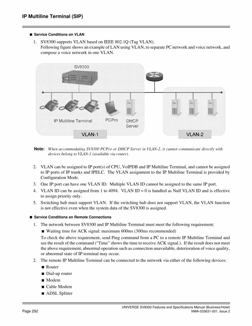
UNIVERGE SV8300 Features and Specifications Manual (Business/Hotel)Page 292 NWA-033631-001, Issue 2
IP Multiline Terminal (SIP)
Service Conditions on VLAN
1. SV8300 supports VLAN based on IEEE 802.1Q (Tag VLAN).Following figure shows an example of LAN using VLAN, to separate PC network and voice network, andcompose a voice network in one VLAN.
Note: When accommodating SV8300 PCPro or DHCP Server in VLAN-2, it cannot communicate directly withdevices belong to VLAN-1 (available via router).
2. VLAN can be assigned to IP port(s) of CPU, VoIPDB and IP Multiline Terminal, and cannot be assignedto IP ports of IP trunks and IPELC. The VLAN assignment to the IP Multiline Terminal is provided byConfiguration Mode.
3. One IP port can have one VLAN ID. Multiple VLAN ID cannot be assigned to the same IP port.
4. VLAN ID can be assigned from 1 to 4094. VLAN ID = 0 is handled as Null VLAN ID and is effectiveto assign priority only.
5. Switching hub must support VLAN. If the switching hub does not support VLAN, the VLAN functionis not effective even when the system data of the SV8300 is assigned.
Service Conditions on Remote Connections
1. The network between SV8300 and IP Multiline Terminal must meet the following requirement:
Waiting time for ACK signal: maximum 600ms (300ms recommended)
To check the above requirement, send Ping command from a PC to a remote IP Multiline Terminal andsee the result of the command (“Time” shows the time to receive ACK signal.). If the result does not meetthe above requirement, abnormal operation such as connection unavailable, deterioration of voice quality,or abnormal state of IP terminal may occur.
2. The remote IP Multiline Terminal can be connected to the network via either of the following devices:
Router
Dial-up router
Modem
Cable Modem
ADSL Splitter
UNIVERGE SV8300 Features and Specifications Manual (Business/Hotel)NWA-033631-001, Issue 2 Page 293
IP Multiline Terminal (SIP)
3. The IP Multiline Terminal can be assigned to Local Connection Mode or Remote Connection Mode byentering the Administrator Mode of the IP Multiline Terminal. After the operation mode of the terminalis changed (Local to Remote, or vice versa), login operation is required again. The differences betweenLocal Connection Mode and Remote Connection Mode are as follows:
4. Individual Location number can be assigned for Local Connection Mode and Remote Connection Mode,on a station number basis, by system programming. The IP Multiline Terminal can work based on thelocation number in each mode. For parameters assigned for each Location number, refer to #13 of OverallConditions. When the Location number for the station is changed, login operation is required again.
5. Following shows an example of remote connections. Because the IP station can have only two-operation mode (=Location number), when the number of re-mote sites (Location numbers) is over two, there is a case that the appropriate communications may notbe available. Refer to Example 2 for details.
Location number in each operation mode for each IP station:
<IP stations in Location #0: STA. 200 and 201>
Remote Connection Mode : Location #1
Local Connection Mode : Location #0
<IP stations in Location #1: STA. 202 and 302>
Remote Connection Mode : Location #1
Local Connection Mode : Location #0 or #2
<IP stations in Location #2: STA. 300 and 301>
Remote Connection Mode : Location #1
Local Connection Mode : Location #2
Operation mode for each IP terminal:
<IP terminals in Location #0>
Local Connection Mode
<IP terminals in Location #1>
Remote Connection Mode
<IP terminals in Location #2>
Local Connection Mode
Example 1: When Sta. 200 logs in Location #1
STA. 200 logs out from Location #0, and then logs in from IP terminals in Location #1. STA. 200works in Remote Connection Mode (because IP terminals in Location # 1 are assigned to Remote Con-nection Mode.), under the conditions of Location #1 (because STA. 200 in Remote Connection Modeis assigned to operate under the condition of Location #1.). In this case, the appropriate communica-tion is available because the operating condition of STA. 200 matches the actual Location number (Lo-cation #1).
Item Local Connection Mode Remote Connection Mode
Confirmation to Connect IP Ter-minal
1 time per minute 1 time per day(10 minutes from 00:00 a.m.)
Clock Control SV8300 sends clock signal to IP terminal on a minute basis.
SV8300 sends clock signal to IP Multiline Terminal when the IP Multiline Terminal is logged in or the clock data is entered by sys-tem data.

UNIVERGE SV8300 Features and Specifications Manual (Business/Hotel)Page 294 NWA-033631-001, Issue 2
IP Multiline Terminal (SIP)
Example 2: When Sta. 200 logs in Location #2
STA. 200 logs out from Location #0, and then logs in from IP terminals in Location #2. STA. 200works in Local Connection Mode (because IP terminals in Location # 2 are assigned to Local Connec-tion Mode.), under the conditions of Location #0 (because STA. 200 in Local Connection Mode is as-signed to operate under the condition of Location #0.). In this case, the appropriate communicationmay not be available because the operating condition of STA. 200 (Location #0) does not match theactual Location number (Location #2).
6. Following features are not available for IP terminals at remote sites:
Multiple Line Operation
Assignment of feature keys which the LED indication and ringer is controlled by other IP terminals
Service Conditions on Automatic Program Download
1. For program upgrade, the FTP or TFTP server is required.
2. This service is available for the IP Multiline Terminal with Peer-to-Peer connections.
3. Maximum of four terminals can be upgrade at the same time regardless of the type of upgrade.
4. Firmware version filed in FTP/TFTP server is assigned by the system data. When the latest firmware ver-sion is filed in the server, be sure to update the system data.
5. When the FTP server is used for program upgrade, login from the IP Multiline Terminal with a login name"anonymous" and password "SV8300" (authentication by FTP server is required).
UNIVERGE SV8300 Features and Specifications Manual (Business/Hotel)NWA-033631-001, Issue 2 Page 295
IP Multiline Terminal (SIP)
6. Conditions on Program Upgrade at Appointed Time
a. Program Upgraded at Appointed Time service is available by the system data assignment on a stationclass of service basis.
b. By the same command mentioned above, program upgrade can be retried just one time. When theupgrade results in failure two times in succession, the IP Multiline Terminal operates with previousfirmware.
c. When this service is executed, neither Program Upgrade at Login Time nor Program Upgrade forDesignated Terminal can be executed.
d. PBX checks the firmware version of each terminal starting from the terminal with the smallest LENnumber, and execute this service if required.
e. This service is executed only for the idle terminals. This service is not executed for the terminals inLogout or busy status.
f. The actual starting time of the Program Upgrade at Appointed Time may be varied with a range of +/--1 minute.
g. System data counts the number of terminals that are successfully upgraded and the number ofterminals that result in upgrade failure only when the PBX sends the latest program upgrade messageto the terminals. If the terminals are busy or logged out, system data does not count the number ofterminals in upgrade failure because the PBX does not send the upgrade message to the terminals.
h. Program Upgrade at Appointed Time can be suspended by system data during executing the upgrade.However, you cannot suspend the upgrade of the terminal with "Downloading..." displayed.
7. Conditions on Program Upgrade at Login Time
a. Program Download at Login Time service can be assigned on a system basis.
b. When this service is assigned, retry in download failure status is not available.
c. DT700 series does not support this feature.
8. Conditions on Program Upgrade for Designated Terminals
a. Program Upgrade for Designated Terminals is assigned and executed on the Primary Extensionnumber basis.
b. This service is executed only for idle terminals. This service is not executed for the terminals inLogout status.
c. When this service is assigned, retry in download failure status is not available.
Service Conditions on Terminal Login via NAT
1. A standalone office must have a global address.
2. NAT support version in SV8300 equipment is described in table below. It is required that all equipmentrelated to communications should support NAT. If there is equipment that does not support NAT, one-wayspeech or no tone might occur.
Item Remarks
SIP Multiline Terminal (DT700) Not support
Dterm Series E, Dterm Series i, IP Multiline Terminal (IP enabled / bundle type)
Available with firmware version 2.82 or later
SP30 Softphone Available with 11.2.0.1 or later version

UNIVERGE SV8300 Features and Specifications Manual (Business/Hotel)Page 296 NWA-033631-001, Issue 2
October, 2008
IP Multiline Terminal (SIP)
3. The SV8300 does not support Network Address Port Translation (NAPT)/IP masquerade, which convertsport number in addition to IP address, because the IPS cannot control IP devices if the port number ischanged.
Conditions on IP Multiline Station for Terminal Login via NAT
1. IP Multiline Station (including SoftPhone) can be connected at remote location from IPS through NAT. Seerequired firmware version in table above. However, NAT cannot be connected through multiple stages.
2. It is required to set different location number between each network connected through NAT in system dataprogramming. Do not set the same location number to the terminal that is not accommodated under the sameNAT. However, multiple location numbers can be used under the same NAT.
3. It is required to set NAT, as the assigned IP address at login of the terminal is not changed before logout.
Conditions on P2P CCIS for Terminal Login via NAT
1. CCIS Inter-office communications are not available when the offices are connected through NAT.
Service Conditions on MH240 Terminal
1. This feature is available from 8300R2 software.
2. To use this feature, WLAN access point conforming to IEEE802.11b/g is required, in addition to MH240terminal.
3. Up to 1024 of MH240 terminals can be accommodated (One MH240 terminal is counted as one IP station).
4. When originator number is not notified, incoming call history is not left.
5. When terminating in dedicated line, same operation is required as trunk line termination.
6. MH240 has only eight function keys.
7. When MH240 is out of zone and the user originates for MH240 out of zone, originator listens to RBT. Butif Logout Transfer is set in MH240, incoming calls out of cell can be transferred.
8. Features related to incoming voice call (Internal Zone Paging and Hands Free Answerback etc.) cannot beused.
9. MUTE key setting (“F5013” is set on function key) in Multiline Terminal cannot be used. Please use MUTEfeature (pressing OK key while calling), which is original for terminals.
10. Only MAC address authentication is supported as login system to SV8300. Override is not available.
11. The following features are not supported.
- Multicast related feature
- SIP encapsulation, SRTP (However encapsulation of wireless section is supported)
- NAT traversal
12. Supported Codec is as follows
Codec : G.711µ -Law, G.711A-Law, G.729a
Payload Size: 20ms-40ms
13. The following features locally operate on terminal side unlike existing DT series.
- LCD Contrast change
- Directory, outgoing/incoming call history (Center Dial by Name is not supported)
- Distinctive ringing selection, LED control for incoming call(In MH240 Config, changing ringing tone direction and LED pattern direction is available per types ofstation/ trunk line/ Dial by Name registration number.)
UNIVERGE SV8300 Features and Specifications Manual (Business/Hotel)NWA-033631-001, Issue 2 Page 297
October, 2008
IP Multiline Terminal (SIP)
14. If the number of originator is registered in MH240 Dial by Name, the priority of terminating operation isthe highest.
15. Firmware download from SV8300 is not available.
UNIVERGE SV8300 Features and Specifications Manual (Business/Hotel)Page 298 NWA-033631-001, Issue 2
IP Trunk (SIP)
IP Trunk (SIP)
General Description
SV8300 supports Session Initiation Protocol (SIP)-based connections with a German Provider, toplink. TheSV8300 supports the below functions.
• DOD calls to toplink network• DID calls from toplink network• Calling Line Identifications - Presentations (CLIP)• Calling party number display on Digital Multiline Terminal• Session Timer (Send/receive keep alive signals)• Receive fragment packets (max. 3000 bytes)• Codec selection• Fault message registration
- SV8300 reboot (SIP trunk, CPU)
- Link disconnect
- Session timer - timeout
• Alternating Routing to PSTN
- When SIP trunk or SIP network is failed, SV8300 can reroute the outgoing call to PSTN. (Max. 6routes, COT/LDT/ODT/DTI/CCT/PRT/BRT can be selected)
• Add/delete E.164 “+” sign
- Add “+” sign in front of telephone number (outgoing call)
- Delete “+” sign in front of telephone number (incoming call)
• NAT Support Note
The SIP trunk supports network configuration via a router with NAT/NAPT function (NAT: Network Ad-dress Translator, NAPT: Network Address Port Translator). This enables efficient use of global IP address.
Note: When the NAT function is used, it is necessary to an inter-working test with providers and routers before-hand.
• RTP Monitoring/Statistics
The SIP trunk can monitor if RTP packets are correctly received during the SIP trunk call is established. Ifno RTP packets are received for 10 seconds, the SIP trunk connection can be released and the fault messageis stored in the CPU. This feature also provides functions for analyzing problems regarding SIP trunk calls.It can collect call logs on SIP trunk calls. The below statistics information can be retrieved by PCPro.
- Call start time
- Call end time
- IP address of the opposite party
- Number of RTP (sending, receiving, receiving-lost)
• Out-band DTMF
The SIP trunk supports the out-band DTMF based on RFC2833. This feature provides DTMF digits trans-mission between the SV8300 SIP Trunk and an external SIP Telephone using RTP packets (out-of-bandsignals), instead of using regular audio packets.

UNIVERGE SV8300 Features and Specifications Manual (Business/Hotel)NWA-033631-001, Issue 2 Page 299
October, 2008
IP Trunk (SIP)
• Tone Disabler
This feature is designed for improved FAX communications over SIP network. By detecting phase inver-sion of FAX signal tone (V.25 2100Hz tone), the system changes a setting of an echo canceller and NLP(Non Liner Processor) for the SIP trunk connection.
• RTCP Support
The SV8300 supports Real Time Control Protocol (RTCP) conformed to RFC1899 for SIP trunk connec-tions.
a. When a RTP communication starts, the SV8300 sends RTCP (SRwithSDES and Receiver RRwithSDES). SR: Sender Report, RR: Receiver Report
b. When the RTP communication ends, the SV8300 sends RTCP (SRwithBYE).
c. When the RTP communication starts, the SV8300 receives RTCP and reflects required data in thereceived RTCP packet to Report Block of RTCP (RRwithSDES).
• Source IP Address Check
For secure communications, the SV8300 checks a source IP address for packets received from a port as-signed as SIP control port by system data programming. If the source IP address is different from the IPaddress assigned as SIP server, the SV8300 rejects those packets.
Station Application
Not applicable
Operating Procedure
No manual operation is required.
Service Conditions
1. SIP Trunk feature key are required.
2. Below table shows a summary of basic specifications of the SIP trunk interface.
Description Specifications
Main blade 64VoIPDB, 128VoIPDB
Maximum channel of SIP in SV8300 system 96 ch per system
Network Interface 10BASE-T/100BASE/1000 BASE-TX, Auto Negotiation
Codec G.711, G.729a
Payload size 20,30,40 ms
Port Number SIP: 5060, RTP: 10000-10191 (default)
Jitter Buffer size Max. 300 ms
Silence suppression Not Supported
Echo Canceller G.168 (64 ms)
FAX Pass-through (G.711)
DTMF Pass-through (G.711), RFC 2833
VLAN Tag VLAN (IEEE802.1p)
QoS IP Precedence, Diffserv

UNIVERGE SV8300 Features and Specifications Manual (Business/Hotel)Page 300 NWA-033631-001, Issue 2
October, 2008
IP Trunk (SIP)
3. One system can accommodate maximum 96 channels (trunks) of SIP trunks, and maximum 512 channelsincluding CCIS and PRI trunks.
4. Number of simultaneous calls
5. SV8300 supports basic origination and termination features with SIP. The basic origination and terminationfeatures include call origination, call termination, abandoned call, and call release. No SIP supplementaryservice is supported.
6. Advance verification is needed for connections. No normal operation is guaranteed for connection with un-verified equipment.
7. Terminating System (Interpretation method of called number)
a. Tie line termination
• SV8300 defines the termination destination with dialed number development assuming that thecalled number was originated from Tie line. The call can be terminated at the following:
- Station
- Attendant Console
- Trunk (tandem connection)
• When the call is terminated at a station, the last one to eight digits of the called number can be treat-ed as the station number.
• When the call is terminated at a trunk, the number can be added or deleted, using LCR number de-velopment. (Max. 10 digits for deletion / Max. 32 digits for addition).
b. DID termination
• The last one to eight digits of the called number is treated as a DID number.
• The following terminating system can be set with DID number conversion:
- Station termination (termination at an extension assigned to the DID number)
- TAS
- Attendant Console
- Attendant Console + TAS
• Maximum 999 DID numbers can be handled.
• DID number that is not registered is handled as Tie Line termination.
• Automated Attendant and DISA cannot be used.
PAD - 14dB to + 14 dB
Routing Strict routing or loose routing selectable
Codec Payload 1 UNIT
G.711
20 ms 96
30 ms 96
40 ms 96
G.729a
20 ms 96
30 ms 96
40 ms 96
Description Specifications
UNIVERGE SV8300 Features and Specifications Manual (Business/Hotel)NWA-033631-001, Issue 2 Page 301
IP Trunk (SIP)
8. Origination Operating Method
SV8300 originates a call with LCR number development.
9. Hold/Transfer functions with SIP are not supported.
10. Ringing Tone Setting
The ringing tone for SIP incoming calls can be set by system data programming.
Conditions on NAT Support
1. DHCP cannot be used because the IP address of the router side must be fixed.
2. VLAN and this feature cannot be used together.
3. A router must be selected in consideration of NAT/NAPT processing capacity and use bandwidth in accor-dance with channel capacity of SIP trunk. The recommended model is IX series router (IX1050, IX2010).
4. For conditions of IP address and use port, coordination between the SIP trunk and the router is required.
5. When the router supports NAT only, the number of SIP trunk can be accommodated is limited to 1.
6. For mounting more than one SIP trunk, NAPT feature is required in the router, and the SIP server must sup-port multiple-port.
7. When more than one SIP trunk are mounted and are put under the control of two routers, one of SIP trunkuse port must be changed so that call processing and RTP port number are not overlapped.
8. In the case of above condition (6), confirm that SIP signaling can operate in the port number other than“5060”, including the connected devices.
9. Communication under the same NAT is possible only for SV8300-to-SV8300 call.
10. Communication under the same NAT is possible with up to 8 of own SIP trunk and other SIP trunk (includ-ing ones in other SV8300.
11. For communication under the same NAT, 320 or more must be put as interval between each RTP base portnumber.
12. This feature cannot be used in point-to-multipoint connection. It is usable only in point-to-point connection.
Conditions on RTP Monitoring
1. Whether the related call is released or not by RTP monitoring is specified per system basis in system dataprogramming.
2. If RTP is not received for approximately 10 seconds while the call is in progress, the SIP trunk sends thefault notification to the CPU to release the path.
3. Even when “the related call is not released” is set, if RTP is not received for approximately 10 seconds, thefault notification is sent only once. But the path is not released.
4. The RTP monitoring starts when one packet is received from the other party after the path was established.Even while ringing, it is monitored if RTP is received.
5. When the path is released by the RTP monitoring, the SIP disconnect message is not sent to the other party.
Conditions on RTP Statistics
1. This feature can be enabled on a SIP trunk blade basis in system data programming.
2. The timer of SIP trunk is used for the call start time/call end time in the call log, and it may not be the sameas the system clock.
3. Refer also to the VoIP Log Collection features and specifications (Call Log Collection) for details.
UNIVERGE SV8300 Features and Specifications Manual (Business/Hotel)Page 302 NWA-033631-001, Issue 2
IP Trunk (SIP)
Conditions on Out-band DTMF
1. When the out-band DTMF packets are received from the external SIP Telephone, the SV8300 detects thedigits information from the received RTP packets and send the DTMF tones to the SV8300 station.
2. When sending the out-band DTMF packets to the external SIP Telephone, the SV8300 converts the DTMFtones received from the station to the RTP packets based on RFC2833, instead of regular audio packets.
3. RFC2833 out-band DTMF that can be sent/received are 0 to 9, “*” and “#”. “A”, “B”, “C” and “D” are notsupported.
4. For RFC2833 out-band DTMF, own RTP payload type is “101” as default setting, and it can be changed insystem data programming.
5. For RFC2833 out-band DTMF, the regeneration time of DTMF to be sent to SIP network is specified insystem data programming. (Default setting: 160 ms)
Conditions on Tone Disabler
1. This feature can be enabled on a SIP trunk card basis in system data programming (default: disabled).
2. With the Tone Disabler set to “enable”, when switching to FAX by detecting V.25 tone (2100 Hz) with aphase inversion from the DSP, EC/NLP is set to OFF and the DSP is started. And when switching to FAXby detecting V.25 tone (2100 Hz) without a phase inversion, EC/NLP is set as the same as voice, and theDSP is started.
3. With the Tone Disabler set to “disable”, regardless of with or without phase inversion, EC/NLP is set as thesame as voice.
4. Regardless of whether the Tone Disabler is set to “enable” or “disable”, when switching to FAX by detect-ing a tone other than V.25 (2100 Hz), it is set as the same as voice.
Conditions on RTCP Support
1. The RTCP can be sent periodically or randomly by system data programming. When the periodic sendingis assigned, the cycle of the RTCP can be assigned from 5sec to 12sec. When the random sending is as-signed the cycle of the RTCP is random value between 5sec to 30sec.
2. The sending pattern (cyclic or random) and the sending cycle can be assigned per SIP trunk blade basis.
3. The first RTCP is sent 500ms after the RTP starts sending.
4. During the RTP sending is stopped due to call hold, the RTCP sending is also stopped.
Kind of DTMF Notation in RTP message
(DECIMAL)
0 - 9 0,1,2,3,4,5,6,7,8,9
# 11
* 10

UNIVERGE SV8300 Features and Specifications Manual (Business/Hotel)NWA-033631-001, Issue 2 Page 303
IP Trunk (SIP)
Conditions on Source IP Address Check
1. This feature can be allowed or denied on a per-trunk card basis.
2. This feature is available for a Point-to-Point connection only. The Point-to-Multipoint connection cannotuse this feature.
3. This feature checks the source IP address of the received packets and one of the below IP address.
a. IP address for SIP Server
b. Destination IP address for SIP trunk
c. IP address stored in the DNS cache table, which the host name of the SIP server is translated by DNS.
4. Below table shows a maximum number of SIP servers, which the source IP address is to be checked.
Office data for SIP server registrationThe maximum number of SIP server whose IP
address is used for source address check (number/PKG)
IP address for SIP Server 1
Destination IP address for SIP trunk 8
IP address stared in the DNS cache table 1

UNIVERGE SV8300 Features and Specifications Manual (Business/Hotel)Page 304 NWA-033631-001, Issue 2
Last Number Redial
Last Number Redial
General Description
This feature allows users to redial the last station-to-station or outside number they dialed using a feature accesskey or a feature access code. This is useful when the called station is busy or does not answer.
The Multiline Terminal with LCD can redial the last 10 numbers dialed. Refer to the Call History features andspecifications document for details.
Station Application
All stations and Attendant Consoles.
Operating Procedure
From a Digital Multiline Terminal
1. Press the Redial key followed by #.
2. The system will redial the last number dialed from that station.
From a Single Line Telephone
1. Go off-hook and receive dial tone.
2. Dial the Last Number Redial feature access code.
3. The system will redial the last number dialed from that station.
From an Attendant Console
1. Press an idle LOOP key.
2. Press the LNR key followed by #.
3. The system will redial the last number dialed from that attendant.
Service Conditions
1. The maximum number of digits that can be stored for Last Number Redial is 32.
2. Dialing digits after going off-hook replaces previously stored digits with the new digits.
3. When the Step Call feature is used, the final destination number is stored in memory.
4. Pressing the Redial key when the Multiline Terminal is idle displays the stored number on the LCD, andturns on the Speaker LED.
5. This feature stores numbers dialed on the Multiline Terminal's primary or secondary extension, or Direct-Trunk Appearances. This feature does not store Dial Intercom or data calls.
6. If the system is designated as KF registration, this feature is not available.

UNIVERGE SV8300 Features and Specifications Manual (Business/Hotel)NWA-033631-001, Issue 2 Page 305
Least Cost Routing - 3/6 Digit
Least Cost Routing - 3/6 Digit
General Description
This service feature allows the system to be programmed to route outgoing calls over the most economical fa-cility (WATS, FX, DDD). Based on the individual area code and office code dialed (6-digit analysis), the sys-tem examines the programmed tables and uses the trunk in the order specified.
Station Application
All stations.
Operating Procedure
1. Lift the handset and receive dial tone.
2. Dial the trunk access code and receive dial tone again.
3. Dial the area code, office code and telephone number.
4. The system automatically completes the call using the most economical route.
Service Conditions
1. Least Cost Routing can be programmed to choose a route based on the following criteria:
• Digits dialed (first three or six digits of the outside number).
• Day of Week
• Time of Day
• Tenant number
• Route Advance
In addition, a special Digit Code Table is used to interpret the one, two, or three leading digits of the areacode: e.g., 01XX....X: International Call; 0: Operator Call; 0XXX: Toll Operator Call. The system exam-ines the Digit Code Table when an ORT timeout has occurred after dialing leading digits.
2. In addition to selecting the route, the system can be programmed to:
• Add the prefix digit 1 for use with FX lines requiring 1+ dialing.
• Add up to 32 digits in front of the number dialed by the station user to allow for equal access accom-modation, or for secondary common carrier access or Central Offices that do not provide equal access.
• Delete the area code (for FX trunks).
• Delete all digits, or up to eight digits from the number dialed.
• Allow or deny access to a specific trunk route based on the office code dialed.
3. All trunk routes in the system can be accessed using LCR (including DDD, Tie, FX, WATS, etc.). Restric-tion on outgoing calls and Code Restriction assignments are applied.
4. The following programmable tables are available:
• Digit Code Table - Up to eight tables of area codes are used to determine the route to be selected. Al-though area codes are normally three-digit codes, this table can be assigned with one to eight-digitcodes. These codes can be assigned to select any other LCR table.

UNIVERGE SV8300 Features and Specifications Manual (Business/Hotel)Page 306 NWA-033631-001, Issue 2
Least Cost Routing - 3/6 Digit
• Route Pattern Table - Up to 256 Route Advance tables are available, each with 4 entries. If more than4 entries are required, up to 8 entries can be provided by combining two route pattern tables.
• LCR Pattern Table - Up to 256 tables are available for assignment of digits to be added or deleted. Also,the office code dialed can be checked to determine whether service is available for a specific officecode, and whether a prefix 1 should be added. This table can be used in conjunction with toll restrictionassignment for combined LCR/toll restriction capability. Refer to the Code Restriction Features andSpecifications.
• Tenant Pattern Table - Up to 16 tables are used to select a route pattern table. The programmer canmake the system select a route pattern table based on the tenant with which the caller is associated. Thisallows sharing of LCR and toll restriction capability among multiple tenants, while providing for theindividual needs of each tenant. Each of the 64 tables can be assigned a route pattern table for each ofthe 64 tenants.
In addition, the special Digit Code Table is used for assigning the same digits as the leading one, twoor three digits of the area code assigned to the Digit Code Tables above (e.g. 00XX.....X: InternationalCall, 0: Operator Call, 0XXX:Toll Operator Call use the special Digit Code Table). The system exam-ines the special Digit Code Table when an ORT timeout has occurred after dialing leading digits.
• Date Pattern Table - Up to 4 day-of-week tables determine whether a route pattern table, tenant patterntable, or a time pattern table is used next in the routing procedure.
• Time Pattern Table - Up to 8 time-of-day tables determine whether a route pattern or tenant pattern tableis used next in the routing procedure. The time is military time and can be input in half-hour increments(00:00 - 23:30).
• Office Code Pattern Tables - Up to 50 tables contain office codes to be checked to see if a prefix digit1 must be added, and to see if the office code dialed is allowed or denied for a specific trunk route (Ser-vice area check).
• Digit Addition Pattern Table - Up to 256 tables are available for assigning digit addition pattern. Up to32 digits, including pauses, can be added.
5. Assignment of LCR is on an access code basis. All trunk access codes can be assigned for LCR. Up to 3different LCR access codes can be assigned, per numbering plan, providing flexibility in choosing routesby access code. When LCR is implemented, all stations within the system are subject to the LCR process.
6. To provide a group of stations access to trunks that are not subject to LCR, the associated trunk routesshould be given different access codes (not assigned to LCR). Other stations can be restricted from accessto these trunk routes.
7. Direct trunk appearances on Multiline Terminals are not subject to the LCR process.
8. If the system is designated as KF registration, this feature is not available.
9. The following flow charts describe LCR system operation.

UNIVERGE SV8300 Features and Specifications Manual (Business/Hotel)NWA-033631-001, Issue 2 Page 307
Least Cost Routing - 3/6 Digit
Isfirst digit anLCR access
code?
START
No Normal operation(no LCR)
Get LCR code todigit code
developmentpattern
Is anLCR code to
digit developmentpattern as-
NoReorder tone
signed?
Yes
Yes
Receive next digit
Check assignmentfor matched
pattern
Is amatchfound?
No
Yes
Is adigit code
developmentpattern as-
YesCheck new digit
code developmentpattern table
signed?
No
Is aday of weekpattern as-
Yes Check day ofweek assignment
signed?
No
A
Is aroute, tenant,or time pattern
assigned?
No Reorder tone
Yes
What patternis assigned?
Time
Tenant
C
Route
B D

UNIVERGE SV8300 Features and Specifications Manual (Business/Hotel)Page 308 NWA-033631-001, Issue 2
Least Cost Routing - 3/6 Digit
Is atime of day pattern
assigned?
Yes
No
Is atenantpattern
assigned?Yes Get route pattern
to be used
No
Is a routepattern Yes
Reorder tone
assigned?
No
A
B
Check time of dayassignment
D
What pattern isassigned?
Get first priorityroute and go to
assignedLCR/TR table
TenantRoute
None
C
Is atrunk restriction
pattern as-signed?
Yes
No
Istrunk route
busy?Yes
No
Is a6 digit
restriction Yes
assigned?
No
Check trunkrestriction table
Allowed ordenied?
Allowed
Is this thelast priority
route?
Reorder tone
Yes
No
Get next priorityroute and go to
assigned LCR/TRtable
Check 6 digittrunk pattern
Denied
Allowed ordenied?
Allowed Denied Reorder tone
E
Check restrictionclass
Reorder tone

UNIVERGE SV8300 Features and Specifications Manual (Business/Hotel)NWA-033631-001, Issue 2 Page 309
Least Cost Routing - 3/6 Digit
Is adigit addition pattern as-
signed?
Yes
No
E
Check digit addition pattern;
add digitsaccordingly
Deletearea code?
Yes
No
Delete area code
Deleteall digits?
Yes
No
Seize a trunkin first trunk route
Number ofdigits to bedeleted?
Yes
No
Delete digitsaccordingly
Seize a trunk inselected priority
trunk routeand dial

UNIVERGE SV8300 Features and Specifications Manual (Business/Hotel)Page 310 NWA-033631-001, Issue 2
Line Lockout
Line Lockout
General Description
This feature automatically releases a station from the common equipment if the station remains off-hook forlonger than a programmed interval before dialing. Howler tone may be programmed to be sent to the station inLine Lockout.
Station Application
All stations.
Operating Procedure
For Line Lockout
1. The station user goes off-hook and receives dial tone.
2. If the user doesn't begin dialing within approximately 12 seconds, reorder tone is received.
3. After 30 seconds of reorder tone, the station is automatically placed into the Line Lockout condition andreceives no tone.
4. Upon replacing the handset, the station is released from the Line Lockout condition.
For Line Lockout with howler tone assigned
1. The station user goes off-hook and receives dial tone.
2. If the user doesn't begin dialing within approximately 12 seconds, reorder tone is received.
3. After 30 seconds of reorder tone, the station is automatically placed into the Line Lockout condition andhowler tone (30 seconds on, 30 seconds off) is sent to the station.
4. Upon replacing the handset, the station is released from the Line Lockout condition.
Service Conditions
1. A station in Line Lockout condition cannot receive or originate calls.
2. The Attendant cannot activate any feature to a station in a Line Lockout condition.
3. Howler tone can be allowed or denied on a per station basis.
4. This feature will also be activated if 12 seconds elapse between dialing digits.

UNIVERGE SV8300 Features and Specifications Manual (Business/Hotel)NWA-033631-001, Issue 2 Page 311
Line Preselection
Line Preselection
General Description
This feature provides the station user with two ways to select an idle, held, recalling, or ringing line before goingoff-hook.
Station Application
All Multiline Terminals.
Operating Procedure
1. Press the desired line key.
2. Lift the handset or press the Speaker key and receive dial tone, or answer the incoming call.
OR
1. Press the line key and receive dial tone or answer the incoming call. (This procedure is programmable insystem programming on a system basis.)
Service Conditions
1. A line key whose associated LED is steadily lit cannot be seized by pressing that key.
2. When the desired line key is pressed, line preselection will remain in effect for 6 seconds. After 6 seconds,line selection returns to the Prime Line, if assigned.
3. Line Preselection has priority over Ringing Line Pickup and Prime Line assignment.
UNIVERGE SV8300 Features and Specifications Manual (Business/Hotel)Page 312 NWA-033631-001, Issue 2
Maid Status
Maid Status
General Description
This feature allows the Hotel/Motel (H/M) Front Desk Instrument, Property Management System (PMS) termi-nal, or guest room station (using special access code) to register the condition of each guest room.
Station Application
All stations except House Phones.
Operating Procedure
To set Maid Status from the Hotel/Motel Front Desk Instrument
1. Press the STS key.
2. Dial the desired function status code.
3. Press the STS key again.
4. Dial the guest room number.
5. Press the SET key. The above two steps can be repeated for other stations.
6. Press the RLS key.
OR
1. Press the STS key.
2. Dial the guest room number.
3. Press the SET key - Room Status is displayed. The above two steps can be repeated for other stations.
4. Press the STS key again.
5. Dial the desired function status number code.
6. Press the SET key. The above two steps can be repeated for other stations.
7. Press the RLS key.
To set Maid Status from a guest room station by maid or repair person
1. Lift the handset and receive dial tone.
2. Dial the Maid Status feature access code and receive special dial tone.
3. Dial the Maid ID code.
4. Dial the desired function status number code.
5. Receive service set tone, then restore the handset.
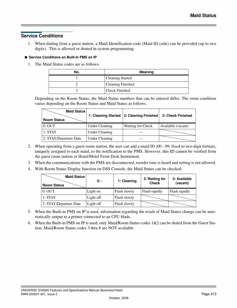
UNIVERGE SV8300 Features and Specifications Manual (Business/Hotel)NWA-033631-001, Issue 2 Page 313
October, 2008
Maid Status
Service Conditions
1. When dialing from a guest station, a Maid Identification code (Maid ID code) can be provided (up to twodigits). This is allowed or denied in system programming.
Service Conditions on Built-in PMS on IP
1. The Maid Status codes are as follows.
Depending on the Room Status, the Maid Status numbers that can be entered differ. The room conditionvaries depending on the Room Status and Maid Status as follows.
2. When operating from a guest room station, the user can add a maid ID (00 - 99; fixed to two-digit format),uniquely assigned to each maid, to the notification to the PMS. However, this ID cannot be verified fromthe guest room station or Hotel/Motel Front Desk Instrument.
3. When the communications with the PMS are disconnected, reorder tone is heard and setting is not allowed.
4. With Room Status Display function on DSS Console, the Maid Status can be checked.
5. When the Built-in PMS on IP is used, information regarding the result of Maid Status change can be auto-matically output to a printer connected to an CPU blade.
6. When the Built-in PMS on IP is used, only Maid/Room Status codes 1&2 can be dialed from the Guest Sta-tion. Maid/Room Status codes 3 thru 8 are NOT available.
No. Meaning
1 Cleaning Started
2 Cleaning Finished
3 Check Finished
Maid Status
Room Status1: Cleaning Started 2: Cleaning Finished 3: Check Finished
0: OUT Under Cleaning Waiting for Check Available (vacant)
1: STAY Under Cleaning —
2: STAY/Departure Date Under Cleaning —
Maid Status
Room Status0: - 1: Cleaning
2: Waiting for Check
3: Available (vacant)
0: OUT Light on Flash slowly Flash rapidly Flash rapidly
1: STAY Light off Flash slowly
2: STAY/Departure Date Light off Flash slowly
UNIVERGE SV8300 Features and Specifications Manual (Business/Hotel)Page 314 NWA-033631-001, Issue 2
Message Center Interface (MCI)
Message Center Interface (MCI)
General Description
This feature provides an interface with a customer supplied Voice Mail System (VMS) that can send MessageWaiting lamp control data to the system.
The Message Center Interface (MCI) can provide the following operations:
1. When terminating the call to the VMS, the system sends call connection status information to the VMSthrough the MCI.
2. The VMS sends the Message Waiting Lamp on data to the MCI.
3. The system, upon receiving this control data from the MCI, illuminates the Message Waiting lamp of thecorresponding station.
4. The VMS, upon receiving retrieved message information, will send the Message Waiting lamp control datarequesting the system to extinguish the Message Waiting lamp of the corresponding station.
Station Application
All stations.
Operating Procedure
To originate a voice mail message
1. Go off hook and receive dial tone.
2. Dial the voice mail pilot number and receive ringback tone.
3. Follow the instructions given by the VMS.
To set call forwarding to a VMS
• Call Forwarding - All Calls • Split Call Forwarding - All Calls• Call Forwarding - Busy Line • Split Call Forwarding - Busy Line • Call Forwarding - No Answer • Split Call Forwarding - No Answer
1. Go off hook and receive dial tone.
2. Dial the Call Forwarding or Split Call Forwarding feature access code and receive feature dial tone.
3. Dial the voice mail extension number and receive service set tone.
The LCD displays:
[SET xxxx]
VMS: Voice mail extension number
Connection when an extension line number whose call forwarding is set to a VMS is called from another station
1. Go off hook and receive dial tone.
2. Dial the desired station number and receive ringback tone. The LCD displays:
[CF ALL xxxx]

UNIVERGE SV8300 Features and Specifications Manual (Business/Hotel)NWA-033631-001, Issue 2 Page 315
Message Center Interface (MCI)
VMS: Voice mail extension number
3. Follow the instructions given by the voice mail system.
To retrieve a voice mail message from the voice mail system
1. The Message Waiting lamp is lit or the LCD displays:
[MESSAGE]
2. Go off hook and receive dial tone.
3. Dial the voice mail extension number and receive ringback tone. The LCD displays:
[ xxxx]
VMS: Voice mail extension number
4. Follow the instructions given by the voice mail system.
Service Conditions
1. The Voice Mail System (VMS) is interfaced to the system through the LC blade. (The LC provides discon-nect supervision in the form of a momentary loop open circuit.)
2. The UCD or Station Hunting feature is usually provided with the VMS station.
3. One RS-232C port on the CPU blade is required to make a data link with a customer supplied VMS.
4. Messages can be retrieved from any Multiline Terminal, DTMF telephone, but not from DP telephones.
5. The MCI is available to a direct call or a forwarded call from a station/trunk/Attendant to the VMS. Fordetails of the connecting patterns, refer to the System Hardware Manual/Programming Manual.
6. Stations can set Call Forwarding or Split Call Forwarding - All Calls, No Answer, and Busy Line to theVMS. The system sends out incoming call information to the VMS. A call to a station that has Call For-warding set to the VMS is automatically answered by the VMS.
7. The MCI can control the LCD display of a Multiline Terminal for “MESSAGE” Indication. The number ofmessages is not displayed.
8. When the Message Waiting lamp control is activated with the MCI, the lamp control from the followingequipment will not be provided:
• From the Property Management System (PMS)• From the station (by dialing the access code)• From the Direct Station Selection (DSS) Console• From the Hotel/Motel Attendant Console• From the Hotel/Motel Front Desk Instrument• From the Attendant Console
9. Only one system should be programmed (via system programming) to control Message Waiting lampsthrough the CCIS network.
10. The system controls Message Waiting lamps normally when the time interval between messages is a min-imum of 350 milliseconds or more.
11. When the VMS interface line does not answer, all of the messages are sent out from the I/O port of the CPU.
12. If the VMS is not ready for information receiving (Busy Status), the CPU blade can temporarily store up to16 call records in its internal memory. If the maximum of 16 call records is stored and a 17th is generated,the system will write over the oldest stored record.

UNIVERGE SV8300 Features and Specifications Manual (Business/Hotel)Page 316 NWA-033631-001, Issue 2
October, 2008
Message Center Interface (MCI)
When the RS port on the CPU is used for the data link to the VMS, the CPU can store up to 15 call records.If a 16th call record is generated when the CPU stores 15 call records, the system will write over the oldeststored record.
13. The Voice Mail Integration (Inband) feature can be combined with voice mail through the MCI in the sys-tem. The Voice Mail Integration (Inband) feature and MCI feature can coexist in one system and either canbe selected per VMS (VMS station number) by system programming.
14. When terminating a call with the ANI information to the VMS through the MCI, the system can send theANI information to the VMS, if required. This is not available through CCIS interface.
15. In 8300R1 software, RS Port only in UNIT#1 can be used. In 8300R2 software or later, RS Ports inUNIT#1, #2, #3 can be used.
16. The same type of equipment cannnot be connected to multiple RS ports.

UNIVERGE SV8300 Features and Specifications Manual (Business/Hotel)NWA-033631-001, Issue 2 Page 317
Message Registration
Message Registration
General Description
This feature provides output from the system to a call accounting system using LAN connector. This allows theHotel/Motel clerk to retrieve the information needed to charge for local and toll calls.
Station Application
Not applicable.
Operating Procedure
No manual operation is required.
Service Conditions
1. The Station Message Detail Recording call record information is used to provide Message Registration in-formation to a call accounting system.
2. The call accounting system must be locally provided and compatible with the system.
3. Refer to Station Message Detail Recording Features and Specifications for more information.
4. When the call accounting system is Property Management System (PMS), call charge information for in-coming calls and tandem calls cannot be output to the PMS.

UNIVERGE SV8300 Features and Specifications Manual (Business/Hotel)Page 318 NWA-033631-001, Issue 2
Message Reminder
Message Reminder
General Description
This feature allows a user or Attendant to turn on the message waiting (MW) lamp of a Single Line Telephone,or the Message Reminder (MSG) LED of a Multiline Terminal (if assigned).
Station Application
All stations.
Operating Procedure
To set Message Reminder from a Single Line Telephone
1. Lift the handset and receive dial tone.
2. Dial the Message Reminder set access code.
3. Dial the desired station number and receive feature dial tone.
4. The MSG LED on the dialed Multiline Terminal or MW lamp on the dialed Single Line Telephone lights.
To set Message Reminder from a Multiline Terminal without calling the station to be set
1. Lift the handset or press the Speaker key and receive dial tone.
2. Dial the Message Reminder set access code.
3. Dial the desired station number. Feature dial tone is received and the LCD displays SET XXXX (whereXXXX is the dialed station number).
4. The MSG LED on the dialed Multiline Terminal or MW lamp on the dialed Single Line Telephone willlight to indicate a message has been set.
To set Message Reminder from a Multiline Terminal (after dialing the station to be set)
1. Lift the handset or press the Speaker key and receive dial tone.
2. Dial the desired station number. Ringback tone or busy tone is received.
3. Press the Message Reminder (MSG) key, or dial 6, if single digit feature access codes are enabled. Serviceset tone is received and the LCD displays SET XXXX (where XXXX is the dialed station number).
4. The MSG LED on the dialed Multiline Terminal or MW lamp will light to indicate a message has been set.
To retrieve a message from a Single Line Telephone or Multiline Terminal
1. Lift the handset and receive dial tone.
2. Dial the Message Reminder search access code.
3. Dial 2. The station that set the message is automatically called.
4. Converse when the call is answered.
OR
1. Lift the handset and receive dial tone.
2. Dial the Message Reminder retrieve access code.
UNIVERGE SV8300 Features and Specifications Manual (Business/Hotel)NWA-033631-001, Issue 2 Page 319
Message Reminder
3. The station that set the message is automatically called.
To clear the message indication without calling the station that set the message, from a Single Line Tele-phone or a Multiline Terminal
1. Lift the handset and receive dial tone.
2. Dial the Message Reminder search access code.
3. Dial 3. The message indication is cleared.
4. Restore the handset.
5. If more than one message has been set, repeat the above procedure as required.
To Search/ Retrieve/ Cancel a message from a Multiline Terminal with LCD
1. Press the Speaker key or lift the handset and receive dial tone.
2. Dial the Message Reminder Search access code; the LCD displays: MESSAGE XXXX (where XXXX is thestation number that set the message) and the time the message was sent.
3. Three options are now available:
• Dial 1 to see the next message
• Dial 2 to call the displayed station
• Dial 3 to clear the message in the display
To call the first station that set a message, from a Multiline Terminal with a MSG key
1. Lift the handset, or press the Speaker key, and receive dial tone.
2. Press the MSG key. The first station that set a message is called.
3. Use the handset to speak when answered.
OR
1. Lift the handset and receive dial tone.
2. Dial the Message Reminder retrieve access code.
3. The station that set the message is automatically called.
4. Converse when answered.
To set a message from the Attendant Console
1. Press an idle LOOP key.
2. Dial the Message Reminder feature access code.
3. Dial the desired station number and receive feature dial tone. Message indication is set.
4. Press the RELEASE key to return to an idle condition.
To cancel a message from the Attendant Console
1. Press an idle LOOP key.
2. Dial the Message Reminder cancel access code.
3. Dial the desired station number and receive feature dial tone. Message indication is canceled.
4. Press the RELEASE key to return to an idle condition.

UNIVERGE SV8300 Features and Specifications Manual (Business/Hotel)Page 320 NWA-033631-001, Issue 2
Message Reminder
To cancel a message from the station that set it
1. Lift the handset and receive dial tone.
2. Dial the Message Reminder cancel code.
3. Dial the desired station number and receive feature dial tone. The message is cleared at the dialed station.
4. Restore the handset.
Service Conditions
1. Single Line Telephones must be connected to a 4LC/8LC blade for this feature to operate. Single Line Tele-phones must be equipped with message waiting lamps for 70 vdc.
2. Multiline Terminals can be assigned a MSG key for use with this feature. This line button serves as an in-dicator for received messages, and allows setting of Message Reminder to other stations (after dialing thestation number).
3. A maximum of four messages can be set to one station. If a fifth message is attempted, reorder tone is heardand the LCD at the setting station shows: RESTRICT (when LCD is provided.)
4. A maximum of 200 messages can be set from stations in one system.
5. Message indications are battery backed up and are not lost due to power failure or initialization of the sys-tem.
6. In Multiple Console Operation, messages set by one Attendant cannot be canceled by another Attendant.
7. Messages can be set to a station in any status condition (idle, busy, in Line Lockout, etc.). Message indi-cations are not provided when a Single Line Telephone handset is off-hook.
8. When a Multiline Terminal calls a station that is forwarded and then presses the MSG key, the message isleft at the station to which the call was forwarded.
9. When all stations in a hunt group are busy, messages set by a Multiline Terminal using the MSG key areleft at the called station.
10. Voice Mail Systems that provide in-band signaling for this purpose may be able to set Message Remind-er(s).
11. Operating procedures and service conditions of a message waiting LED on Multiline Terminals withoutLCD are the same as those of Single Line Telephones, except that the message waiting LED remains onwhen the terminal is off hook.
12. To set Message Reminder service for Multiple Stations, set Message Reminder for the first station, wait forfeature dial tone, and then set the reminder for the next station.
13. The number of messages is displayed while the Multiline Terminal is in an idle state.
14. The number of messages displayed includes the setting of Message Waiting.

UNIVERGE SV8300 Features and Specifications Manual (Business/Hotel)NWA-033631-001, Issue 2 Page 321
Message Waiting
Message Waiting
General Description
Message Waiting - Single Lamp
This feature allows the Attendant Console, Hotel/Motel (H/M) Front Desk Instrument, administrative station,Voice Mail System (VMS) or Property Management System (PMS) terminal to light a lamp (on an uninterrupt-ed or interrupted basis) on a Single Line Telephone or Multiline Terminal to indicate a message is waiting.
Message Waiting - Multiple Lamp
This feature allows the Attendant Console, Hotel/Motel (H/M) Front Desk Instrument, administrative station,Voice Mail Systems (VMS) or Property Management System (PMS) terminal to light multiple line keys on aMultiline Terminal, to indicate a message is waiting. This allows multiple individuals who share the same Dig-ital Multiline Terminal to receive their own Message Waiting indication.
Voice Message Waiting
In addition to the LED indication control, this feature also provides the Voice Message Waiting service that anoriginating station user can set the Message Waiting with a recorded message by using the Builtin VPS on CPU.
• Voice Message Waiting - System
An originating station user can choose the recorded message to be set by dialing the message number asso-ciated. The messages are recorded by the predetermined station.
• Voice Message Waiting - Individual
When setting Message Waiting, an originating station user announces the message to be recorded after di-aling the station number.
Station Application
All stations.
Operating Procedure
From the Hotel/Motel Front Desk Instrument
To set Message Waiting (Single and Multiple Lamp)
1. Press the MW key.
2. Dial the desired station number.
3. Press the SET key.
4. The above two steps can be repeated for additional stations.
5. Press the RELEASE (RLS) key.
To cancel Message Waiting (Single and Multiple Lamp)
1. Press the MW key.
2. Dial the desired station number.
UNIVERGE SV8300 Features and Specifications Manual (Business/Hotel)Page 322 NWA-033631-001, Issue 2
Message Waiting
3. Press the RESET key.
4. The above two steps can be repeated for additional stations.
5. Press the RELEASE key.
To set Message Waiting while receiving ringback tone or busy tone
1. Press the MW key.
2. Press the SET key.
3. Press the RELEASE key.
To cancel Message Waiting while receiving ringback tone or busy tone
1. Press the MW key.
2. Press the RESET key.
3. Press the RELEASE key.
From the Attendant Console
To set Message Waiting (Single and Multiple Lamp)
1. Dial the desired station number.
2. Press the MW key.
3. Press the START key.
4. Press the RELEASE key.
To cancel Message Waiting (Single and Multiple Lamp)
1. Dial the desired station number.
2. Press the MW key.
3. Press the RESET key.
4. Press the RELEASE key.
From an administrative station
To set Message Waiting (Single and Multiple Lamp)
1. Lift the handset and receive dial tone.
2. Dial the Message Waiting set access code (default *9).
3. Dial the desired station number and receive service set tone.
4. Restore the handset.
To cancel Message Waiting (Single and Multiple Lamp)
1. Lift the handset and receive dial tone.
2. Dial Message Waiting reset access code (default *9).
3. Dial the desired station number and receive service set tone.
4. Restore the handset.Note: Property Management System (PMS) procedures will vary, depending on the locally-provided PMS.
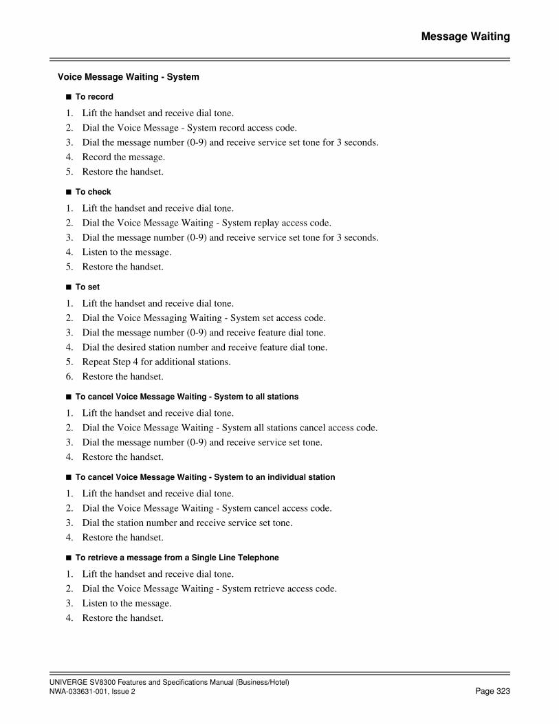
UNIVERGE SV8300 Features and Specifications Manual (Business/Hotel)NWA-033631-001, Issue 2 Page 323
Message Waiting
Voice Message Waiting - System
To record
1. Lift the handset and receive dial tone.
2. Dial the Voice Message - System record access code.
3. Dial the message number (0-9) and receive service set tone for 3 seconds.
4. Record the message.
5. Restore the handset.
To check
1. Lift the handset and receive dial tone.
2. Dial the Voice Message Waiting - System replay access code.
3. Dial the message number (0-9) and receive service set tone for 3 seconds.
4. Listen to the message.
5. Restore the handset.
To set
1. Lift the handset and receive dial tone.
2. Dial the Voice Messaging Waiting - System set access code.
3. Dial the message number (0-9) and receive feature dial tone.
4. Dial the desired station number and receive feature dial tone.
5. Repeat Step 4 for additional stations.
6. Restore the handset.
To cancel Voice Message Waiting - System to all stations
1. Lift the handset and receive dial tone.
2. Dial the Voice Message Waiting - System all stations cancel access code.
3. Dial the message number (0-9) and receive service set tone.
4. Restore the handset.
To cancel Voice Message Waiting - System to an individual station
1. Lift the handset and receive dial tone.
2. Dial the Voice Message Waiting - System cancel access code.
3. Dial the station number and receive service set tone.
4. Restore the handset.
To retrieve a message from a Single Line Telephone
1. Lift the handset and receive dial tone.
2. Dial the Voice Message Waiting - System retrieve access code.
3. Listen to the message.
4. Restore the handset.
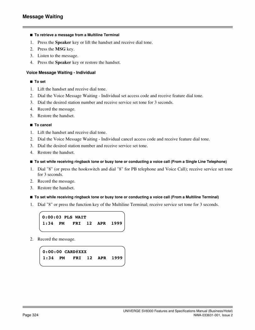
UNIVERGE SV8300 Features and Specifications Manual (Business/Hotel)Page 324 NWA-033631-001, Issue 2
Message Waiting
To retrieve a message from a Multiline Terminal
1. Press the Speaker key or lift the handset and receive dial tone.
2. Press the MSG key.
3. Listen to the message.
4. Press the Speaker key or restore the handset.
Voice Message Waiting - Individual
To set
1. Lift the handset and receive dial tone.
2. Dial the Voice Message Waiting - Individual set access code and receive feature dial tone.
3. Dial the desired station number and receive service set tone for 3 seconds.
4. Record the message.
5. Restore the handset.
To cancel
1. Lift the handset and receive dial tone.
2. Dial the Voice Message Waiting - Individual cancel access code and receive feature dial tone.
3. Dial the desired station number and receive service set tone.
4. Restore the handset.
To set while receiving ringback tone or busy tone or conducting a voice call (From a Single Line Telephone)
1. Dial "8" (or press the hookswitch and dial "8" for PB telephone and Voice Call); receive service set tonefor 3 seconds.
2. Record the message.
3. Restore the handset.
To set while receiving ringback tone or busy tone or conducting a voice call (From a Multiline Terminal)
1. Dial "8" or press the function key of the Multiline Terminal; receive service set tone for 3 seconds.
2. Record the message.
0:00:03 PLS WAIT
1:34 PM FRI 12 APR 1999
0:00:00 CARD#XXX
1:34 PM FRI 12 APR 1999

UNIVERGE SV8300 Features and Specifications Manual (Business/Hotel)NWA-033631-001, Issue 2 Page 325
Message Waiting
3. Message Waiting lamp is lit on the called station (X=the number of messages).
4. Restore the handset.
(XXX=Card No.)
To set while receiving ringback tone or busy tone or conducting a voice call (From the Attendant Console)
1. Dial "8"; receive service set tone for 3 seconds.
2. Press the RELEASE key or CANCEL key.
To retrieve a message (From a Single Line Telephone)
1. Lift the handset and receive dial tone.
2. Dial the Voice Message Waiting - Individual retrieve access code.
3. Listen to the message.
4. Restore the handset.
To retrieve a message (From a Multiline Terminal)
1. Press the Speaker key or lift the handset and receive dial tone.
2. Press the MSG key.
3. Listen to the message.
4. Press the Speaker key or restore the handset.
Service Conditions
Message Waiting - Single and Multiple Lamp
1. When Check Out is performed, any remaining messages will be output to the printer and cleared from mem-ory.
2. The Message Waiting function can be set even when the guest station is busy. The Message Waiting lampwill not light while the guest station has the handset in use (on Single Line Telephones).
3. Message Waiting status is displayed by the Message Waiting lamp on Single Line Telephones or MultilineTerminals.
4. Message Waiting can be automatically cleared by talking to the Attendant Console or the Hotel/Motel FrontDesk Instrument (on a system basis). If Message Waiting is not automatically cleared, the reset operationis required.
5. A 4LC/8LC blade is required to provide Single Line Telephones with the Message Waiting function. SingleLine Telephones must be equipped with Message Waiting lamps for 70VDC.
MESSAGE__X
1:34 PM FRI 12 APR 1999
REC COMPLETE XXX
1:34 PM FRI 12 APR 1999
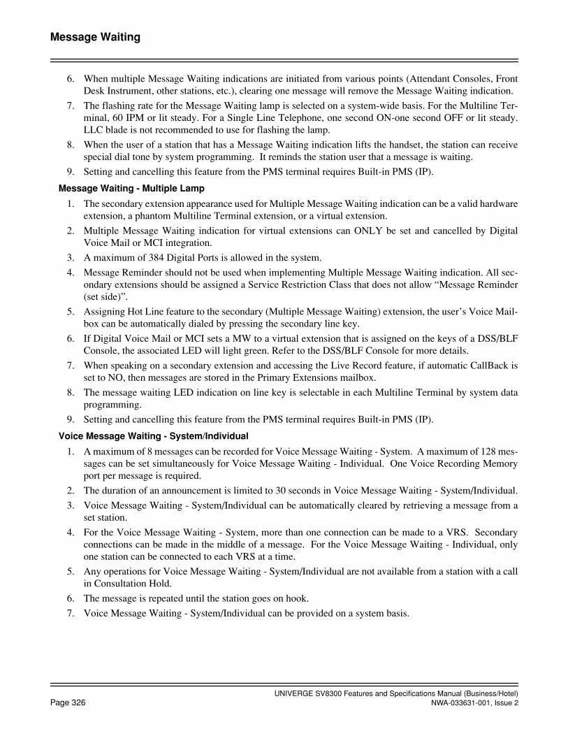
UNIVERGE SV8300 Features and Specifications Manual (Business/Hotel)Page 326 NWA-033631-001, Issue 2
Message Waiting
6. When multiple Message Waiting indications are initiated from various points (Attendant Consoles, FrontDesk Instrument, other stations, etc.), clearing one message will remove the Message Waiting indication.
7. The flashing rate for the Message Waiting lamp is selected on a system-wide basis. For the Multiline Ter-minal, 60 IPM or lit steady. For a Single Line Telephone, one second ON-one second OFF or lit steady.LLC blade is not recommended to use for flashing the lamp.
8. When the user of a station that has a Message Waiting indication lifts the handset, the station can receivespecial dial tone by system programming. It reminds the station user that a message is waiting.
9. Setting and cancelling this feature from the PMS terminal requires Built-in PMS (IP).
Message Waiting - Multiple Lamp
1. The secondary extension appearance used for Multiple Message Waiting indication can be a valid hardwareextension, a phantom Multiline Terminal extension, or a virtual extension.
2. Multiple Message Waiting indication for virtual extensions can ONLY be set and cancelled by DigitalVoice Mail or MCI integration.
3. A maximum of 384 Digital Ports is allowed in the system.
4. Message Reminder should not be used when implementing Multiple Message Waiting indication. All sec-ondary extensions should be assigned a Service Restriction Class that does not allow “Message Reminder(set side)”.
5. Assigning Hot Line feature to the secondary (Multiple Message Waiting) extension, the user’s Voice Mail-box can be automatically dialed by pressing the secondary line key.
6. If Digital Voice Mail or MCI sets a MW to a virtual extension that is assigned on the keys of a DSS/BLFConsole, the associated LED will light green. Refer to the DSS/BLF Console for more details.
7. When speaking on a secondary extension and accessing the Live Record feature, if automatic CallBack isset to NO, then messages are stored in the Primary Extensions mailbox.
8. The message waiting LED indication on line key is selectable in each Multiline Terminal by system dataprogramming.
9. Setting and cancelling this feature from the PMS terminal requires Built-in PMS (IP).
Voice Message Waiting - System/Individual
1. A maximum of 8 messages can be recorded for Voice Message Waiting - System. A maximum of 128 mes-sages can be set simultaneously for Voice Message Waiting - Individual. One Voice Recording Memoryport per message is required.
2. The duration of an announcement is limited to 30 seconds in Voice Message Waiting - System/Individual.
3. Voice Message Waiting - System/Individual can be automatically cleared by retrieving a message from aset station.
4. For the Voice Message Waiting - System, more than one connection can be made to a VRS. Secondaryconnections can be made in the middle of a message. For the Voice Message Waiting - Individual, onlyone station can be connected to each VRS at a time.
5. Any operations for Voice Message Waiting - System/Individual are not available from a station with a callin Consultation Hold.
6. The message is repeated until the station goes on hook.
7. Voice Message Waiting - System/Individual can be provided on a system basis.

UNIVERGE SV8300 Features and Specifications Manual (Business/Hotel)NWA-033631-001, Issue 2 Page 327
Miscellaneous Trunk AccessCCSA Access
Miscellaneous Trunk Access
General Description
This feature allows the connection of various types of external facilities. In addition to Loop and Ground StartTrunks, the following can also be interfaced with the system: CCSA Lines Code Calling Equipment, DictationEquipment, Foreign Exchange (FX) Lines, Radio Paging Equipment, and Wide Area Telephone Service(WATS) lines. Refer to separate features, Direct Inward Dialing (DID), and Tie Line Access for more applica-tions of Miscellaneous Trunk Access.
CCSA Access
General Description
This feature allows connection to or from a CCSA (Common Control Switching Arrangement) network. ACCSA network is a special, privately-leased network constructed for one customer's exclusive use that replacesor augments the public switched network services.
The outgoing connections using CCSA lines are accomplished in the same manner as a normal outgoing call.Incoming calls are received from the CCSA network as a series of digits from the network instead of a ringingsignal, and the connection is established in the same manner as a Direct Inward Dial (DID) or Tie Line connec-tion.
For Tie Line applications, the customers can construct a network with their own numbering plan. In a CCSAapplication, the numbers are issued by the C.O. following the CCSA network numbering plan.
Station Application
All stations.
Operating Procedure
To place an outgoing CCSA call from a station
1. Lift handset and receive dial tone.
2. Dial CCSA feature access code and receive second dial tone from CCSA switch.
3. Dial desired telephone number.
4. Converse when called party answers.
To answer an incoming CCSA call
With Attendant assistance
1. DID lamp flashes and an audible indication is received.
2. Attendant presses either the DID or ANSWER key.
3. Attendant extends call to desired station.

UNIVERGE SV8300 Features and Specifications Manual (Business/Hotel)Page 328 NWA-033631-001, Issue 2
Miscellaneous Trunk AccessCCSA Access
Without Attendant assistance
Lift handset and converse
Service Conditions
1. An access code needs to be assigned for CCSA Access.
2. 4-Wire Tie Line circuits (ODT blade) must be provided for the interface with CCSA network.
3. Immediate, second dial tone, wink start or delay dial operation are available by system data on a trunk routebasis.
4. When the called station is busy, busy tone is returned to the calling party.
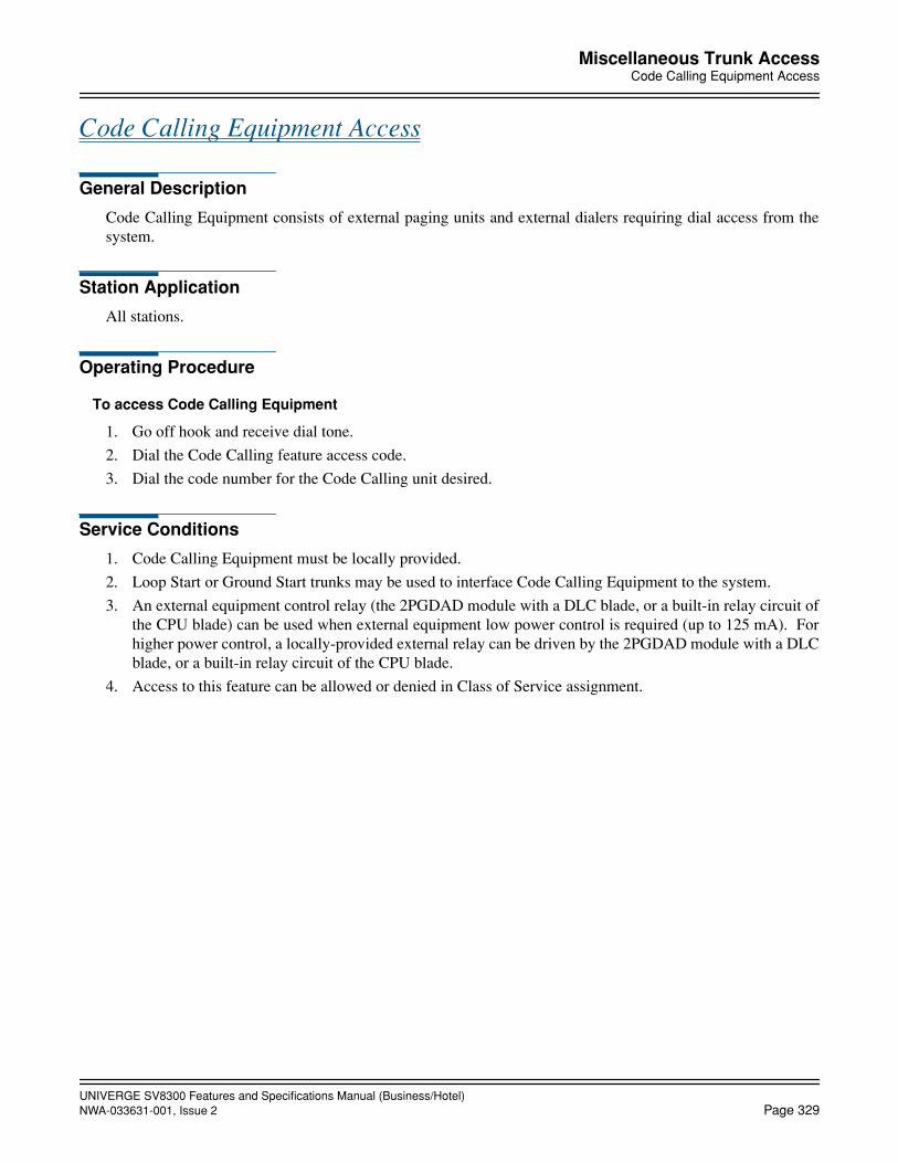
UNIVERGE SV8300 Features and Specifications Manual (Business/Hotel)NWA-033631-001, Issue 2 Page 329
Miscellaneous Trunk AccessCode Calling Equipment Access
Code Calling Equipment Access
General Description
Code Calling Equipment consists of external paging units and external dialers requiring dial access from thesystem.
Station Application
All stations.
Operating Procedure
To access Code Calling Equipment
1. Go off hook and receive dial tone.
2. Dial the Code Calling feature access code.
3. Dial the code number for the Code Calling unit desired.
Service Conditions
1. Code Calling Equipment must be locally provided.
2. Loop Start or Ground Start trunks may be used to interface Code Calling Equipment to the system.
3. An external equipment control relay (the 2PGDAD module with a DLC blade, or a built-in relay circuit ofthe CPU blade) can be used when external equipment low power control is required (up to 125 mA). Forhigher power control, a locally-provided external relay can be driven by the 2PGDAD module with a DLCblade, or a built-in relay circuit of the CPU blade.
4. Access to this feature can be allowed or denied in Class of Service assignment.
UNIVERGE SV8300 Features and Specifications Manual (Business/Hotel)Page 330 NWA-033631-001, Issue 2
Miscellaneous Trunk AccessDictation Equipment Access
Dictation Equipment Access
General Description
This feature permits dial access to customer provided Dictation Equipment, and in some instances allows theuser to maintain telephone dial control of normal dictation system features.
Station Application
All stations.
Operating Procedure
To access the Dictation Equipment from any station
1. Go off hook and receive dial tone.
2. Dial the Dictation Equipment feature access code.
3. Proceed according to operation procedures of the Dictation Equipment.
Service Conditions
1. One trunk circuit is required for each piece of dictation interface equipment accessed.
2. Dictation Equipment must be able to receive DTMF signals if dial control is desired; however, access isalso available with rotary dial signals.
3. Dictation Equipment must be locally provided.
4. Dictation Equipment can be accessed from stations, Attendant Consoles, Tie Lines, or remotely. Refer tothe Direct Inward System Access Features and Specifications.
5. Access to this feature can be allowed or denied in Class of Service assignment.
UNIVERGE SV8300 Features and Specifications Manual (Business/Hotel)NWA-033631-001, Issue 2 Page 331
Miscellaneous Trunk AccessForeign Exchange (FX) Access
Foreign Exchange (FX) Access
General Description
An FX line is a line that is extended and terminated at a distant C.O. With this feature, outgoing calls over theFX line become local calls at the distant C.O.
Station Application
All stations.
Operating Procedure
Outgoing Call from any station
1. Go off hook and receive dial tone.
2. Dial the FX line access code and receive dial tone from distant C.O.
3. Dial the desired telephone number.
(Multiline Terminals can have direct trunk appearances of FX lines).
Incoming call to the Attendant Console
1. The FX lamp at the Attendant Console flashes and an audible signal is received.
2. The Attendant presses key assigned to the FX line or the ANSWER key.
3. The Attendant processes the call in a normal manner.
Service Conditions
1. One circuit on the COT blade is required for each FX line interface.
2. Care should be exercised in system data assignment when using this feature in conjunction with Least CostRouting (LCR), since FX lines may require that the digit 1 be dialed prior to the desired number or that thearea code be deleted.
3. The maximum capacity of all trunk, including FX lines, cannot exceed 256 lines.
4. Access to this feature can be allowed or denied in Class of Service assignment.
5. FX lines can be assigned as Direct In Terminations.
UNIVERGE SV8300 Features and Specifications Manual (Business/Hotel)Page 332 NWA-033631-001, Issue 2
Miscellaneous Trunk AccessRadio Paging Equipment Access
Radio Paging Equipment Access
General Description
This feature provides station users dial access to Radio Paging Equipment, and to selectively tone - or voice/tone-alert individuals carrying pocket paging devices. The paged party (when on premises) can be connectedto the paging party by going to the nearest station and dialing an answer back code.
Station Application
All stations.
Operating Procedure
To page
1. Go off hook and receive dial tone.
2. Dial the Radio Paging Answer Code and receive feature dial tone.
3. Dial the number of the paged radio and receive ring back tone.
4. The on-premises paged party answers. The two parties can converse.
Service Conditions
1. Radio Paging Equipment must be locally provided. Refer to the manufacturer's documentation for the fol-lowing specifications:
• type of tones
• capability of receiving individual radio number
• maximum number of users that can be assigned individual radio access numbers
2. A maximum of 4 digits can be assigned as Radio Paging Equipment Access and answer codes.
3. Individual radio numbers can be a maximum of 4 digits.
4. The Attendant Console can originate a radio paging call.
5. The maximum number of radio paging answer zones is 10.
6. The maximum number of trunk routes that can be assigned radio paging is 10.
7. If the paged party does not answer within 300 seconds, the on-premises paging-answer capability will becancelled. This timing is programmable up to 900 seconds (15 minutes).
8. Access to this feature can be allowed or denied in Class of Service Assignment.

UNIVERGE SV8300 Features and Specifications Manual (Business/Hotel)NWA-033631-001, Issue 2 Page 333
Miscellaneous Trunk AccessWide Area Telephone Service (WATS) Access
Wide Area Telephone Service (WATS) Access
General Description
This feature allows any station user direct dial access to outgoing WATS lines.
Station Application
All stations.
Operating Procedure
Normal call handling procedures apply.
Service Conditions
1. One circuit on the COT blade is required for each WATS line interface.
2. Least Cost Routing and Code Restriction can be applied to WATS lines.
3. The maximum capacity of all lines including WATS Lines cannot exceed 256 lines.
4. Access to this feature can be allowed or denied in Class of Service assignment.

UNIVERGE SV8300 Features and Specifications Manual (Business/Hotel)Page 334 NWA-033631-001, Issue 2
Mobility Access
Mobility Access
General Description
SV8300 supports Mobility Access (MA) feature including enquiry calls and activation/deactivation by a user.This feature allows a user to make/receive telephone calls from a remote location via the PBX, as if the user dofrom his/her desk phone.
• Calls from MA user (DTMF based)
Remote MA user can only access PBX by means of DTMF-digits, like DISA feature. This means that theMA user dials DID number for MA access, receives dial tone, then dials desired internal station number orexternal party number using DTMF. This is valid for normal calls and for enquiry calls. CLI display on theinternal station shows the MA station number. CLI display on the external party shows the CLI number ofthe MA station.
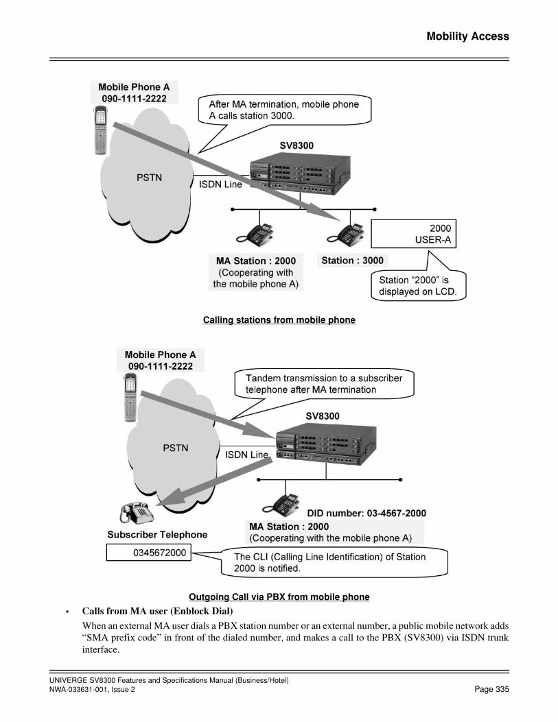
UNIVERGE SV8300 Features and Specifications Manual (Business/Hotel)NWA-033631-001, Issue 2 Page 335
Mobility Access
Calling stations from mobile phone
Outgoing Call via PBX from mobile phone
• Calls from MA user (Enblock Dial)
When an external MA user dials a PBX station number or an external number, a public mobile network adds“SMA prefix code” in front of the dialed number, and makes a call to the PBX (SV8300) via ISDN trunkinterface.

UNIVERGE SV8300 Features and Specifications Manual (Business/Hotel)Page 336 NWA-033631-001, Issue 2
Mobility Access
The SV8300 checks if the received number includes the MA prefix code. If there is the MA prefix code,the SV8300 recognizes a digit after the MA prefix code as a station number or an external number and startscalling the station number or the external number.
The SV8300 also supports the enblock dialing feature for an enquiry call from a second call trigger.Note: This feature is available for Swedish mobile operators only. When this feature is used, the mobile operator
should support this function. Sometimes the mobile operator requests additional payment to allow thisfunction.
Calling stations from mobile phone
• Calls towards MA user (MA Forwarding)
When an internal station or external party makes a call to a MA station, the call is forwarded to a remoteMA user immediately without ringing the MA station. CLI display on the MA user telephone shows theCLI of the calling station number for internal station call, or the MA station number for external party call.

UNIVERGE SV8300 Features and Specifications Manual (Business/Hotel)NWA-033631-001, Issue 2 Page 337
Mobility Access
MA Forwarding at Station access
MA Forwarding at incoming from trunk

UNIVERGE SV8300 Features and Specifications Manual (Business/Hotel)Page 338 NWA-033631-001, Issue 2
Mobility Access
• Activation/deactivation of MA mode from remote telephone
The MA mode can be set or canceled from a remote telephone.
• Activation/deactivation of MA mode from MA station
The MA mode can be set or canceled from a MA station telephone.
• Enquiry calls (triggered by second call)
A remote MA user (e.g.with GSM phone) can activate an enquiry call (triggered by second call) during theconversation of a MA call.
Enquiry call in MA call
• Call Forwarding - All Calls set/cancel from a remote MA user
A remote MA user can activate/deactivate the Call Forwarding - All Calls feature for his/her MA station.In this case, the call towards the MA station is forwarded to the Call Forwarding - All Calls destination,instead of forwarding to the remote MA user. And even with Call Forwarding - All Calls set, the MA ter-mination from the mobile phone is still enabled.
• Call Forwarding - Busy Line when a remote MA user is busy or out of radio zone
When a remote MA user is busy or out of radio zone, a call towards the MA user can be forwarded to theCall Forwarding - Busy Line destination, if it is set for the MA station.
Station Application
All stations
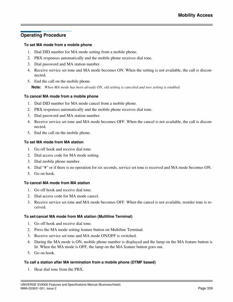
UNIVERGE SV8300 Features and Specifications Manual (Business/Hotel)NWA-033631-001, Issue 2 Page 339
Mobility Access
Operating Procedure
To set MA mode from a mobile phone
1. Dial DID number for MA mode setting from a mobile phone.
2. PBX responses automatically and the mobile phone receives dial tone.
3. Dial password and MA station number.
4. Receive service set tone and MA mode becomes ON. When the setting is not available, the call is discon-nected.
5. End the call on the mobile phone.Note: When MA mode has been already ON, old setting is canceled and new setting is enabled.
To cancel MA mode from a mobile phone
1. Dial DID number for MA mode cancel from a mobile phone.
2. PBX responses automatically and the mobile phone receives dial tone.
3. Dial password and MA station number.
4. Receive service set tone and MA mode becomes OFF. When the cancel is not available, the call is discon-nected.
5. End the call on the mobile phone.
To set MA mode from MA station
1. Go off hook and receive dial tone.
2. Dial access code for MA mode setting.
3. Dial mobile phone number.
4. Dial “#” or if there is no operation for six seconds, service set tone is received and MA mode becomes ON.
5. Go on hook.
To cancel MA mode from MA station
1. Go off hook and receive dial tone.
2. Dial access code for MA mode cancel.
3. Receive service set tone and MA mode becomes OFF. When the cancel is not available, reorder tone is re-ceived.
To set/cancel MA mode from MA station (Multiline Terminal)
1. Go off hook and receive dial tone.
2. Press the MA mode setting feature button on Multiline Terminal.
3. Receive service set tone and MA mode ON/OFF is switched.
4. During the MA mode is ON, mobile phone number is displayed and the lamp on the MA feature button islit. When the MA mode is OFF, the lamp on the MA feature button goes out.
5. Go on hook.
To call a station after MA termination from a mobile phone (DTMF based)
1. Hear dial tone from the PBX.

UNIVERGE SV8300 Features and Specifications Manual (Business/Hotel)Page 340 NWA-033631-001, Issue 2
Mobility Access
2. Dial a desired station number.
To call an outside party after MA termination from a mobile phone (DTMF based)
1. Hear dial tone from the PBX.
2. Dial a trunk access code and desired outside number.
To call a station on an outside party from a mobile phone (Enblock Dial)
1. Dial a desired station number or a trunk access code and desired outside number.The GSM network automatically adds a MA Prefix code in front of the dialed number and send it to thePBX.
To activate an enquiry call
DTMF based:
1. During the conversation of a MA call, the MA user initiates a second call. (See specification of the usedGSM phone. Sometimes just pressing the CALL button can do it.)
2. The internal/external party is placed on consultation hold by GSM network.
3. The MA user dials the DID number for MA access.
4. The PBX checks the CLI of the incoming call and recognizes this is the second call from the same MA user.
5. The PBX disconnects the second call and places the first MA call on consultation hold.
6. The PBX will send dial tone to the GSM network.
7. The MA user dials the desired station/external party number for enquiry. The GSM phone will send this inDTMF-format.
Enblock Dial:
1. During the conversation of a MA call, the MA user initiates a second call. (See specification of the usedGSM phone. Sometimes just pressing the CALL button can do it.)
2. The internal/external party is placed on consultation hold by GSM network.
3. The MA user dials the desired station/external number for enquiry.
4. The PBX checks the CLI of the incoming call and recognizes this is the second call from the same MA user.
5. The PBX disconnects the second call and places the first MA call on consultation hold. The PBX starts call-ing to the station/external party.
To alternate between parties
1. During conversation with a party and a hold party, the MA user initiates a second call.
2. The internal/external party is placed on consultation hold by GSM network.
3. The MA user dials the DID number for MA access.
4. The PBX checks the CLI of the incoming call and recognizes this is the second call from the same MA user.
5. The PBX disconnects the second call and places the conversation party on consultation hold. The (old) holdparty will change into conversation party.
6. The MA user will detect that the second call is disconnected and will switch back to the first MA call.
7. The MA user will hear the party, which is put into conversation.

UNIVERGE SV8300 Features and Specifications Manual (Business/Hotel)NWA-033631-001, Issue 2 Page 341
Mobility Access
To transfer a call
1. During conversation and the presence of a hold party, the MA user disconnects the connection.
2. The PBX detects the disconnection and will connect the party in conversation with the hold party, under thecondition that it is allowed. If not allowed, the parties will be released.
To set Call Forwarding - All Calls from a mobile phone (DTMF based)
1. Dial the DID number for MA termination on the mobile phone.
2. PBX answers automatically and dial tone is received.
3. Dial the Call Forwarding - All Calls feature access code and receive special dial tone.
4. Dial the forwarding destination number.
Station: Station number
Trunk: Trunk access code + outside subscriber number + “#”
Attendant Console: Access code for calling an operator
5. Receive service set tone and the Call Forwarding-All Calls is enabled. If the setting fails, the line will bedisconnected.
6. End the call on the mobile phone.
To cancel Call Forwarding - All Calls from a mobile phone (DTMF based)
1. Dial the DID number for MA termination on the mobile phone.
2. PBX answers automatically and dial tone is received.
3. Dial the Call Forwarding - All Calls cancel code.
4. Receive service set tone and the Call Forwarding - All Calls is disabled. If the cancel fails, the line will bedisconnected.
5. End the call on the mobile phone.
Service Conditions
General Conditions
1. To enable this feature, MA license is required. MA license is provided in increments of one. The license isused for one mobile phone at MA mode setting, and it is released at MA mode cancel. Therefore, the licenseis required for the number in which MA mode can be set simultaneously.
2. This feature can be operated only via ISDN line, and both BRI and PRI can be used. The service of callernumber notification is mandatory.
3. The number of required DID subscriber is as follows.
For MA Termination 1
For MA Mode Setting 1
For MA Mode Cancel 1
Assigned to MA stationSame number of MA
station is recommended
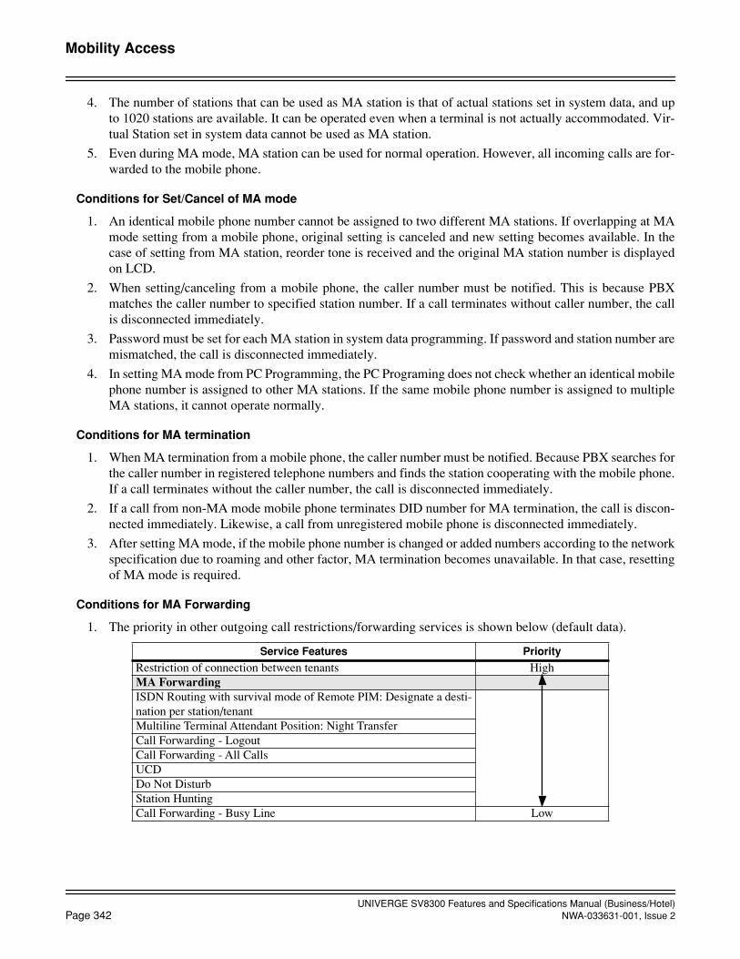
UNIVERGE SV8300 Features and Specifications Manual (Business/Hotel)Page 342 NWA-033631-001, Issue 2
Mobility Access
4. The number of stations that can be used as MA station is that of actual stations set in system data, and upto 1020 stations are available. It can be operated even when a terminal is not actually accommodated. Vir-tual Station set in system data cannot be used as MA station.
5. Even during MA mode, MA station can be used for normal operation. However, all incoming calls are for-warded to the mobile phone.
Conditions for Set/Cancel of MA mode
1. An identical mobile phone number cannot be assigned to two different MA stations. If overlapping at MAmode setting from a mobile phone, original setting is canceled and new setting becomes available. In thecase of setting from MA station, reorder tone is received and the original MA station number is displayedon LCD.
2. When setting/canceling from a mobile phone, the caller number must be notified. This is because PBXmatches the caller number to specified station number. If a call terminates without caller number, the callis disconnected immediately.
3. Password must be set for each MA station in system data programming. If password and station number aremismatched, the call is disconnected immediately.
4. In setting MA mode from PC Programming, the PC Programing does not check whether an identical mobilephone number is assigned to other MA stations. If the same mobile phone number is assigned to multipleMA stations, it cannot operate normally.
Conditions for MA termination
1. When MA termination from a mobile phone, the caller number must be notified. Because PBX searches forthe caller number in registered telephone numbers and finds the station cooperating with the mobile phone.If a call terminates without the caller number, the call is disconnected immediately.
2. If a call from non-MA mode mobile phone terminates DID number for MA termination, the call is discon-nected immediately. Likewise, a call from unregistered mobile phone is disconnected immediately.
3. After setting MA mode, if the mobile phone number is changed or added numbers according to the networkspecification due to roaming and other factor, MA termination becomes unavailable. In that case, resettingof MA mode is required.
Conditions for MA Forwarding
1. The priority in other outgoing call restrictions/forwarding services is shown below (default data).
Service Features Priority
Restriction of connection between tenants HighMA ForwardingISDN Routing with survival mode of Remote PIM: Designate a desti-nation per station/tenantMultiline Terminal Attendant Position: Night TransferCall Forwarding - LogoutCall Forwarding - All CallsUCDDo Not DisturbStation HuntingCall Forwarding - Busy Line Low

UNIVERGE SV8300 Features and Specifications Manual (Business/Hotel)NWA-033631-001, Issue 2 Page 343
Mobility Access
Conditions for enquiry call during conversation of MA call
1. Enquiry calls (triggered by second call) is possible, if the MA user is given the possibility of the making asecond call, with the same CLI as the first call.In case the MA users applies a GSM-connection, the GSM-terminal and the GSM-network provider shouldsupport the function “second call”. Sometimes the GSM-provider requests additional payment to allow thisfunction.In case the MA user applies an ISDN terminal from his/her home, then the line from his/her home to theISDN/PSTN-provider should be configured in such a way, that the same CLI is used for the second call.
2. If the mobile phone ends a call without dialing in hooking state during MA call, the held call receives reor-der tone immediately.
3. If the mobile phone calls another station in hooking state during MA call and ends the call before the calledparty answers, it becomes calling from the held terminal. (Call Transfer before the transfer destination an-swers)
4. When a call is connected after the called party answers in hooking state, if the mobile phone ends the call,the called party and the held terminal are connected. And if the called party ends the call, the mobile phoneand held terminal are connected.
5. During connection with a station by this feature, all service feature operation such as Call Transfer, Holdand Conference operation from the called station is not available.
6. If the mobile phone calls a station in hooking state and receives busy tone due to unassigned number orcalled party busy, the mobile phone can return to the communication with the held call by hooking operationagain. If hooking is operated again while ringing the called party, the mobile phone can return to the com-munication with the held call, in the same manner.
7. In hooking state, the mobile phone can call a station and originate an outgoing call only. Calling an Atten-dant Console and UCD queuing are restricted. Those operations are restricted even if the mobile phone callsa station and the call is forwarded. Operational conditions after MA termination and hooking operation aredescribed below.
8. Placing a trunk on hold by hooking during MA call is available for all the trunk type.When the mobile phone places a trunk on hold by hooking and originates an outgoing trunk call, and thenthe mobile phone ends the call while conversation, the trunk of the called party and the on-hold trunk willbe connected as a tandem connection. However, if tandem connection is restricted between these trunks,both will be released.
Conditions for making mobile phone access look like MA station access
1. When an outgoing call to outside or to CCIS by using MA feature, the caller number notified to the networkvaries by connection pattern. If the caller number per station is not set at outgoing call, the listed directlynumber according to the subscribed line is notified.
2. When using MA feature, a call is treated as a usual trunk incoming and outgoing call and not disguised asit is to OAI. And MA set/cancel is not configured by OAI.
After MA termination After hooking operation
Calling station Allowed Allowed
Outgoing call Allowed Allowed
Calling Attendant Console Allowed Restricted
UCD queuing Allowed Restricted
UNIVERGE SV8300 Features and Specifications Manual (Business/Hotel)Page 344 NWA-033631-001, Issue 2
October, 2008
Mobility Access
3. When connecting Voice Mail after MA termination, Voice Mail side treats the call as connected from MAstation, not from trunk.
4. When calling an Attendant Console after MA termination
- The call terminates the attendant console that deals with MA station tenant.
- Call Incoming Indication button of Attendant Console is an incoming call from CO line 0.
5. For PS/Caller-ID station, the LCD display is same as that of normal CO outgoing and incoming calls, be-cause a call is not disguised using MA feature.
6. When a mobile phone calls a Multiline Terminal after MA termination, not the mobile phone number butthe MA station number is stored in the incoming call record/incoming no answer call record.
Conditions for Call Forwarding - All Calls Setting from Mobile Phone
1. Call Forwarding - All Calls has lower priority than MA Forwarding in default data (see Conditions for MAForwarding), but the priority can be changed for each MA station by class of service. For using this feature,the priority of Call Forwarding - All Calls must be set higher than that of MA Forwarding.
2. As a destination of Call Forwarding - All Calls, a station, Attendant Console or an outside party can be spec-ified.
3. Call Forwarding - All Calls setting operation is available even to the station already having the setting. Inthis case, the new setting will be effective. Cancel operation to the station with no setting is restricted.
4. Set/cancel operation from a mobile phone can be allowed or restricted for each MA station by class of ser-vice.
5. Set/cancel operation from a mobile phone is allowed only at MA termination. Operation from hooking dur-ing MA call is restricted.
6. This feature is enabled even when Call Forwarding - All Calls is set from the MA station or PC Program-ming.
Conditions for Call Forwarding - Busy Line/Out of Zone at MA Forwarding
1. Call Forwarding - Busy Line/Out of Zone is executed when CAUSE of DISC/REL/REL_COMP for SETUP at originating is as follows:
#17: Terminating user is busy #34: No usable lines/channels Note: When the mobile phone is out of zone and the call is connected to out of zone announcement of the carrier,
DISC/REL/REL_COMP is not received. Therefore the call is not forwarded.
2. Whether Call Forwarding - Busy Line/Out of Zone is performed or not can be selected for each MA stationin service restriction class.
3. Call Forwarding - Busy Line/Out of Zone can be set by operation from MA station. Incoming calls fromAnalog CO Line/tie line to MA station without Call Forwarding - Busy Line/Out of Zone setting are termi-nated to the forwarding destination set for each tenant.
4. Call Forwarding - Busy Line/Out of Zone can not be set by operation from a mobile phone.
5. If the forwarding destination is also set to Call Forwarding - All Calls/Busy Line, the call can be forwardedup to 5 times.
6. If the forwarding destination is set to Do Not Disturb, the call is not terminated but restricted. The settingof forwarding destination for each tenant becomes ineffective when the called station is set to Do Not Dis-turb.

UNIVERGE SV8300 Features and Specifications Manual (Business/Hotel)NWA-033631-001, Issue 2 Page 345
Mobility Access
7. If the forwarding destination is set to MA mode, MA Forwarding is available only once. If the destinationis also busy, the second Call Forwarding - Busy Line/Out of Zone will not be executed and the call will berestricted.
8. When the call is terminated to the station by Call Forwarding - Busy Line/Out of Zone, LCD display of thestation will be the same as that when the call is forwarded by Call Forwarding - Busy Line as below. In thiscase, the MA station is displayed as the intermediate station.
9. When the call is terminated to Voice Mail by Call Forwarding - Busy Line/Out of Zone, “Forwarding type= Call Forwarding - Busy Line, Intermediate Station = MA Station” is noticed to the Voice Mail.
Conditions for MA Enblock Dial
1. This feature is available only for Swedish mobile operators.
2. The SV8300 PCPro receives MA Prefix code + PBX station number/external number dialed by the MA user(mobile phone).
3. The maximum number of digits for the MA Prefix code is eight (8). 0 to 9, A (*) and B (#) can be used forthe MA Prefix code.
4. Maximum one (1) MA Prefix code can be used for the MA Prefix code. The maximum number of digitsafter the SMA Prefix code is 16.
• Station number, PBX operator access number and external number can be effective the number afterthe MA Prefix code.
• In case of the external number, trunk access code is also required.
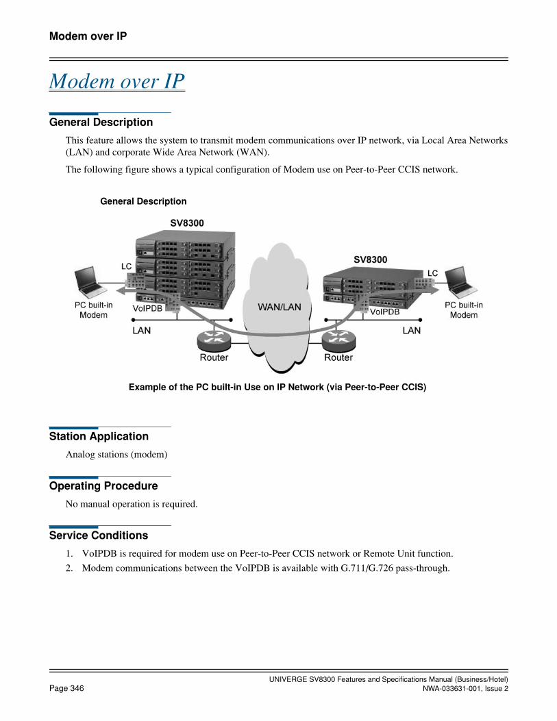
UNIVERGE SV8300 Features and Specifications Manual (Business/Hotel)Page 346 NWA-033631-001, Issue 2
Modem over IP
Modem over IP
General Description
This feature allows the system to transmit modem communications over IP network, via Local Area Networks(LAN) and corporate Wide Area Network (WAN).
The following figure shows a typical configuration of Modem use on Peer-to-Peer CCIS network.
Station Application
Analog stations (modem)
Operating Procedure
No manual operation is required.
Service Conditions
1. VoIPDB is required for modem use on Peer-to-Peer CCIS network or Remote Unit function.
2. Modem communications between the VoIPDB is available with G.711/G.726 pass-through.
General Description
Example of the PC built-in Use on IP Network (via Peer-to-Peer CCIS)
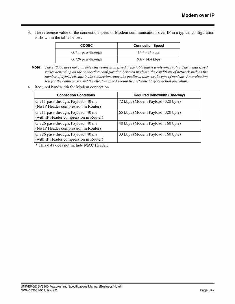
UNIVERGE SV8300 Features and Specifications Manual (Business/Hotel)NWA-033631-001, Issue 2 Page 347
Modem over IP
3. The reference value of the connection speed of Modem communications over IP in a typical configurationis shown in the table below.
Note: The SV8300 does not guarantee the connection speed in the table that is a reference value. The actual speedvaries depending on the connection configuration between modems, the conditions of network such as thenumber of hybrid circuits in the connection route, the quality of lines, or the type of modems. An evaluationtest for the connectivity and the effective speed should be performed before actual operation.
4. Required bandwidth for Modem connection
CODEC Connection Speed
G.711 pass-through 14.4 - 24 kbps
G.726 pass-through 9.6 - 14.4 kbps
Connection Conditions Required Bandwidth (One-way)
G.711 pass-through, Payload=40 ms(No IP Header compression in Router)
72 kbps (Modem Payload=320 byte)
G.711 pass-through, Payload=40 ms(with IP Header compression in Router)
65 kbps (Modem Payload=320 byte)
G.726 pass-through, Payload=40 ms(No IP Header compression in Router)
40 kbps (Modem Payload=160 byte)
G.726 pass-through, Payload=40 ms(with IP Header compression in Router)
33 kbps (Modem Payload=160 byte)
* This data does not include MAC Header.

UNIVERGE SV8300 Features and Specifications Manual (Business/Hotel)Page 348 NWA-033631-001, Issue 2
October, 2008
Multiline Terminal
Multiline Terminal
General Description
There are five Multiline Terminals that can be used with the system.
• DT300/DT700 Series• Dterm Series i • Dterm Series EThe following features apply to these Multiline Terminals.
Service Conditions
1. Power Saving mode can be set to DT Series/Dterm Series i, to darken the lamps on DT/Dterm if the DT/Dterm
is not operated for a certain time. This feature is not available in IP Multiline Terminal (Dterm IP/DT700).
a. The timer to activate Power Saving mode is set by system data programming.
b. In the following state, the Power Saving mode is cancelled.
• When a ringing is on
• When a voice path is on (Using BGM, terminating Voice Call)
c. When Dterm Series i is used in the mode of other than Dterm Series i, or Dterm Series i isaccommodated in Remote Unit, Power Saving mode is not available.
Conditions on Change the names of services displayed on DESI-less LCD
1. This feature is available from 8300R2 software.
2. This feature is available in DESI-less terminals and Sophisticated terminals of DT700 Series (DT750).
3. Change of the displayed name is available for maximum 100 types of services. However, multiple namescannot be assigned for one feature.
4. Maximum eight alphanumeric one byte characters can be displayed.
Conditions on DT300/DT700 series variability of time for lighting on backlight
1. This feature is available from 8300R2 software.
2. This feature is available for DT300/DT700 Series except for Economy.
3. The parts where time for lighting on backlight is controlled are following: Main LCD part backlight /DESI-less LCD part backlight /Digit key part backlight.
4. This feature is ineffective when backlight is ineffective by operation of terminal side menu. (In DT300/DT700 Series, setting backlight effective /ineffective by menu key of terminal is available.)
Service Conditions on DT300/DT700 Series display enhancement
1. This feature is available from 8300R2 software.
2. LCD screen can be set black or white by system data.

UNIVERGE SV8300 Features and Specifications Manual (Business/Hotel)NWA-033631-001, Issue 2 Page 349
October, 2008
Multiline TerminalAutomatic Idle Return
3. Available terminals are as follows.
X: Available—: Not ApplicableN/A: Not Available
Automatic Idle Return
General Description
This feature returns a station to the idle state after 3 seconds of reorder tone is received due to the distant enddisconnecting.
Station Application
Multiline Terminals.
Operating Procedure
No manual operation is required.
Service Conditions
1. Automatic Idle Return applies when the call was made using the Speaker key .
2. The call can be either an internal or external call. If it is an external call, a remote disconnect signal fromthe C.O. must be supplied.
3. Automatic Idle Return can be allowed or denied on a system basis.
Economy Value Sophisticated
DT300 Series N/A X —
DT700 Series X X N/A
UNIVERGE SV8300 Features and Specifications Manual (Business/Hotel)Page 350 NWA-033631-001, Issue 2
October, 2008
Multiline TerminalCalled Station Status Display
Called Station Status Display
General Description
This feature provides a display on the status of a called station on the LCD of the calling Multiline Terminal.
Station Application
Multiline Terminals with LCD.
Operating Procedure
1. Lift the handset or press the Speaker key and receive extension dial tone.
2. Dial the desired station.
3. The status of the called station appears on the LCD.
Service Conditions
1. If the called station is idle, the called station's number will flash on the LCD until the call is answered.When the call is answered, the number and the name of the called party will be displayed in the LCD. Thecalled party's name can be assigned in system programming.
2. If the called station is busy, the LCD will display BUSY and the called station's number.
3. If the called station is in Do Not Disturb, the LCD will display DND and the called station's number.
4. If a restricted station is called, the LCD will display RESTRICT and the called station's number.
5. If the called station has set Call Forwarding - All Calls/Busy Line/No Answer, the LCD will display CFALL, CF BUSY, or CF NANS respectively, the called station's number and the target station's number.
6. If the called station is in a Call Pickup group and the call is picked up by another station, the LCD will dis-play PICK, the called station's number, and the number of the station that picked up the call.
7. Refer to the Alphanumeric Display and Elapsed Call Timer features for additional information.

UNIVERGE SV8300 Features and Specifications Manual (Business/Hotel)NWA-033631-001, Issue 2 Page 351
October, 2008
Multiline TerminalCalling Name and Number Display
Calling Name and Number Display
General Description
This feature provides a display on the LCD of the Multiline Terminal receiving a call, indicating the stationnumber or trunk number of the incoming call.
Station Application
Multiline Terminals with LCD.
Operating Procedure
No manual operation is required.
Service Conditions
1. When a call terminates to a line other than the station's Prime Line, the Calling Name and Number Displaywill be indicated only after the ringing line key is pressed or the call is answered. For trunk calls, the LCDdisplays the trunk route name and trunk number. For internal incoming calls on the Prime Line, the LCDdisplays the extension number and caller's name. For Direct Inward Termination (DIT), the LCD displaysDIT, the trunk route name and trunk number.
2. When an incoming call terminates to the Prime Line, the station number and name will be displayed whenthe call begins ringing.
3. Refer to the Alphanumeric Display and Elapsed Call Timer features for additional information.
4. It is possible to choose “flashing or not” of the calling party name or number display, when receiving anincoming call to a Multiline Terminal.
Service Conditions on Calling Name or Number Display on Multiline Terminal before user's answer
1. When the system uses Trunk Direct Appearance or TAS (Trunk Answer from any station) as a trunk callterminating method, the calling party number can be displayed before answering the call.
2. When a call is terminated from a trunk to a particular extension (SLT, Multiline Terminal, Virtual extensionand PS Virtual extension, by Direct Inward Termination (DIT), Direct Inward Dialing, or Automated At-tendant, the calling party number can also be displayed on the Sub Line of Digital Multiline Terminal spec-ified.
3. Max. 8 Multiline Terminals can be assigned per tenant for the answering positions, by system data program-ming. Up to 10 tenants can use this feature.
4. Following information is indicated on the LCD of Multiline Terminal. (The same information as conven-tionally displayed on Prime Line termination is displayed.)
Upper on LCD: Trunk name (such as DDD, TIE) and trunk number
Lower on LCD: Calling number or calling name(No display is provided when no such information is available.)
• In the case of Trunk Direct Appearance or TAS
LCD display is provided for incoming calls in the order of termination to trunks.
• In the case of Sub Line termination

UNIVERGE SV8300 Features and Specifications Manual (Business/Hotel)Page 352 NWA-033631-001, Issue 2
October, 2008
Multiline TerminalCalling Name and Number Display
LCD display is provided for incoming calls in the order of termination to extensions.
a. Termination display is provided at intervals of 128 ms for each Multiline Terminal.
b. Display is provided on up to 8 Multiline Terminals. So, after trunk termination, about 1 second isrequired until display is provided on the last Digital Multiline Terminal.
c. The order of termination display on Multiline Terminals is not fixed. Instead, the order is changedeach time display is provided on a Multiline Terminal. In this way, problems such as “Display is firstprovided on a particular terminal only at all times.” and “A particular terminal has increased load onanswering.” can be avoided.
5. After an incoming call is answered, display is provided in the same way as presently done. display 6 secondsor continuously).
6. Conditions on Multiline Terminal state for termination display
a. When a Multiline Terminal is busy: No display
b. When a Multiline Terminal is idle and Prime Line of the Multiline Terminal is idle: Display
c. When a Multiline Terminal is idle, but a call is terminated to Prime Line of the Multiline Terminal:No display
d. When a Multiline Terminal is idle, but Prime Line of the Multiline Terminal is placed on hold:Display
7. Termination display to the Prime Line takes priority over termination display to Trunk Direct Appearance/TAS.
8. Termination display to Sub Line does not operate for a call terminated as described below.
a. Internal Call from an extension or attendant console (including a trunk call that is placed on hold then is transferred)
b. Recall from Hold/Call Transfer operation
c. Group Call by Pilot Number Dialing

UNIVERGE SV8300 Features and Specifications Manual (Business/Hotel)NWA-033631-001, Issue 2 Page 353
October, 2008
Multiline TerminalDynamic Dial Pad
Dynamic Dial Pad
General Description
This feature allows to make an outgoing call at first hand by pressing a keypad of Multiline Terminal, withoutpressing a Speaker key or going off-hook.
Station Application
Multiline Terminals.
Operating Procedure
Dial the desired station number by pressing a keypad, without pressing a Speaker key or going off-hook.
Service Conditions
1. An extension must be set as a Prime Line.
2. This feature is not available when the prime line is busy.

UNIVERGE SV8300 Features and Specifications Manual (Business/Hotel)Page 354 NWA-033631-001, Issue 2
October, 2008
Multiline TerminalGroup Feature Key
Group Feature Key
General Description
This feature provides the multiple line keys of Multiline Terminal with DSS/BLF function. A station user canmonitor the status of group member stations such as idle, busy, hold and ringing by LED indication of the mul-tiple line keys. If a line is idle, a station user can make a call to the member station by pressing the associatedline key (instead of pressing DSS key). If a line is ringing or is on hold, a station user can pick up the incomingcall or the call on hold by using My Line, and the ringing or held line is made idle.
Station Application
All Digital Multiline Terminals.
Operating Procedure
Note that the operation by pressing the conventional line key completely differs from that by the Group FeatureKey.
To call a group member station
While a Multiline Terminal is idle:
1. Press the desired line key of an idle group member station.
2. On the calling station, the My Line key is lit in green and the called member’s line key is flashing in red.Receive ring back tone.
3. On the called station, the My Line key is flashing in red. Hear ringing.
To pick up an incoming call or a call on hold to a group member station
While a Digital Multiline Terminal is idle:
1. Press the line key of a group member station that is called or on hold by another station or a trunk.
2. On the picking up station, the My Line key is lit in green and the member’s line key lamp turns off. Answerthe incoming call or the call on hold.
3. The originally called or held member’s station becomes idle and the My Line key lamp turns off on the sta-tion.
Service Conditions
Preconditions
1. The Group Feature key is specified by system data programming of each Multiline Terminal key.
2. Specify the My Line as the prime line.
3. Accommodate the My Line and group member’s lines in multiple lines in the Multiline Terminal belongingto the group.
4. The stations belonging to the group are a Single Line Telephone, Digital Multiline Terminal and IP Multi-line Terminal. Do not register a PS or SoftPhone.

UNIVERGE SV8300 Features and Specifications Manual (Business/Hotel)NWA-033631-001, Issue 2 Page 355
October, 2008
Multiline TerminalGroup Feature Key
5. Do not register any station belonging to the group in Station Hunting group or UCD group.
6. Do not register any station belonging to the group in Group Call group.
Conditions when the Multiline Terminal is Idle
1. Group member’s line key status: Idle
a. If My Line cannot be seized, Group Feature Key is disabled, and its status does not change.
b. LED/LCD indications, ring back tone, and ringing on the Multiline Terminal in placing a call are thesame as for ordinary station calls.
2. Group member’s line key status: Incoming call from a station/trunk
a. LED/LCD indications on the Multiline Terminal in answering a call are the same as for conventional call pickup.
b. It is possible to answer an incoming call originated at the attendant console.
c. If My Line cannot be seized (because the Multiline Terminal is being used in multiple lines mode), itis possible to answer an incoming call by using the Sub Line, by system data programming.
d. LED/LCD indications on the Multiline Terminal in answering a call are the same as when theconventional Sub Line key is pressed to answer a call.
3. Group member’s line key status: Call on hold in multiple lines
a. LED/LCD indications on the Multiline Terminal in answering a call are the same as in answering again the call held on the multiple lines.
b. It is impossible to answer a call on Exclusive Hold by another member in multiple lines.
c. If My Line cannot be seized (because the Multiline Terminal is being used in multiple lines mode), itis possible to answer an incoming call by using the Sub Line, by system data programming.
d. LED/LCD indications on the Multiline Terminal in answering a call are the same as when theconventional Sub Line key is pressed to answer a call.
4. Group member’s line key status: Two-party connection in progress
Same as when the conventional line key is pressed (a busy tone is received).
Conditions when a dial tone is being received on the Multiline Terminal (After My Line or a Sub Line or a virtual line is seized by going off-hook or pressing the Speaker key or an ordinary Line key to receive a dial tone)
1. Group member’s line key status: Idle
a. A member on the selected line is called.
b. The seized line (My Line or Sub Line) is used for communication.
c. LED/LCD indications, ring back tone and ringing on the Multiline Terminal in placing a call are thesame as for ordinary station calls.
2. Group member’s line key status: Incoming call from a station/trunk
a. An incoming call on the selected line is picked up and answered.
b. The seized line (My Line or Sub Line) is used for communication.
c. LED/LCD indications on the Multiline Terminal in answering a call are the same as for conventionalcall pickup.
3. Group member’s line key status: Call on hold in multiple lines
a. A call on the selected line is picked up and answered.
b. The seized line (My Line or Sub Line) is used for communication.
UNIVERGE SV8300 Features and Specifications Manual (Business/Hotel)Page 356 NWA-033631-001, Issue 2
October, 2008
Multiline TerminalGroup Feature Key
c. LED/LCD indications on the Multiline Terminal in answering a call are the same as for conventionalresponse to a call on hold.
d. It is impossible to answer a call on Exclusive Hold by another member in multiple lines. In this case,the operations are the same as when the conventional line key is pressed (a busy tone is received).
4. Group member’s line key status: Two-party connection in progress
Same as when the conventional line key is pressed (a busy tone is received).
Conditions when the Multiline Terminal is busy (Communicating with another station or a trunk on My Line)
1. Group member’s line key status: Idle
a. A call is put on Consultation Hold and the member corresponding to the selected line is called.
b. LED/LCD indications, ring back tone and ringing on the Multiline Terminal in placing a call are thesame as for ordinary station calls.
c. If the remote party is an attendant console or ISDN terminal, it is impossible to call the remote party.(Group Feature Key is disabled.)
d. If a call is already on hold, it is impossible to place another call. (Group Feature Key is disabled.)
e. If the local or remote station is being monitored, is being set Camp-On/Call Waiting, is beingWhisper Paged, or is being interrupted, it is impossible to place a call. (Group Feature Key isdisabled.)
2. Group member’s line key status: Two-party connection in progress
Same as when the conventional line key is pressed (a busy tone is received and the call is disconnected).
Conditions for a called line being idle when the group member’s line key is pressed
1. When below feature is being set for the called line (group member station), the call can be forwarded to theforwarding destination number by system data programming.a. Call Forwarding - All Calls d. Call Forwarding - Logoutb. Call Forwarding by Mobility Access e. Attendant Night Transferc. Do not Disturb
2. If Call Forwarding - No Answer is being set for a called line, the call is forwarded to the forwarding desti-nation if the line does not answer within a certain time.
3. If a line is in the Voice-First mode, it is possible to call the line by voice (the voice call conditions remainthe same as those conventional).
4. A called line is not hunted for even if the line belongs to the UCD or Station Hunting group.
5. No Group Call is made even if the called line is the pilot station in Group Call group.
Conditions for a called line is busy when the group member’s line key is pressed
1. No call forwarding is performed for a line even if Call Forwarding - Busy Line is being set for the calledline (Call Forwarding - Busy Line is ignored).
2. No operation is performed for a called line even if the line belongs to the UCD or Station Hunting group.
3. No busy-line function (usually supposed to be performed after a busy tone is received) is performed.
UNIVERGE SV8300 Features and Specifications Manual (Business/Hotel)NWA-033631-001, Issue 2 Page 357
October, 2008
Multiline TerminalGroup Feature Key
Conditions for putting a call on hold
1. After the Group Feature Key is pressed to answer an incoming call or a call held on another line, when com-munication is in progress on My Line, an attempt to put the call on hold again results in the call being heldon My Line.
2. After the Group Feature Key is pressed during communication with a trunk/station to put the call on Con-sultation Hold and to call another line, performing the “hold” operation results in the trunk/station call al-ready on Consultation Hold being held on the another line. (The operating Multiline Terminal becomesidle.)
<Restrictions>
a) Both ringing and voice call are usable to call another line.
b) If another line is a Single Line Telephone, the “hold” attempt is ignored. (The calling state remains.)
c) If an attempt is made to hold a call on another line that is already being called, the state (ringer,Digital Multiline Terminal indication, etc.) of the line is the same as for the conventional RemoteHold function.
d) If an attempt is made to hold a call on another line that is already being called and the line does notanswer within a certain time, the operating Multiline Terminal is recalled. If another line has set CallForwarding - No Answer for that line, the call forwarding setting is ignored and the operatingMultiline Terminal is recalled. The time allowed before the Multiline Terminal is recalled can bespecified by system timer data (Exclusive Hold no-answer timer).
Conditions with Other features
1. Line Preselection
Group Feature Key supports Line Preselection feature only when there is an incoming call directed to theGroup Feature Key. It is required to enable the Line Preselection feature by system data.
2. Caller-ID Display
Caller-ID Display feature displays the calling party’s information of an incoming call or a call on hold whenthe CID key is pressed to enter the CID mode and then the LINE key is pressed.
In the CID mode, the Caller-ID Display is enabled. In no CID mode, the Group Feature Key is enabled.
3. Last Number Redial
If the Group Feature Key is pressed to call another station line, it is not registered as the last number.
4. 24-button Digital Multiline Terminal
Group Feature Key is supported when the Digital Multiline Terminal buttons 17 to 24 are set as the linekeys.
5. Remote UNIT over IP
It is possible to specify a station line accommodated at a remote site for a flexible function button of DigitalMultiline Terminal accommodated at the main site. To the contrary, it is also possible to specify a stationline accommodated at the main site for a flexible function button accommodated at a remote site.
6. SMDR
a. When the Group Feature Key is pressed to answer an incoming call from a trunk, the My Line number of the answering terminal will be a target of incoming SMDR.
b. When the Group Feature Key is pressed to answer a trunk call on hold, the My Line number of theanswering terminal can be a target of outgoing or incoming SMDR depending on the system dataprogramming.
UNIVERGE SV8300 Features and Specifications Manual (Business/Hotel)Page 358 NWA-033631-001, Issue 2
October, 2008
Multiline TerminalGroup Feature Key
7. Ringing Line Pickup
Group Feature Key and Ringing Line Pickup can operate at the same time. When going off-hook while anincoming call is ringing on the Group Feature key on the Multiline Terminal, the operations will be as fol-lows.
a. Normal Ringing Line Pickup
Answer the incoming call by using the incoming line.
b. Ringing Line Pickup + Group Feature Key combination
Answer (pick up) the incoming call by using My Line.

UNIVERGE SV8300 Features and Specifications Manual (Business/Hotel)NWA-033631-001, Issue 2 Page 359
October, 2008
Multiline TerminalHandsfree Unit
Handsfree Unit
General Description
The built-in Handsfree Unit enables full Handsfree operation for both internal and external calls. No optionalHandsfree Unit is required.
Station Application
Multiline Terminals.
Operating Procedure
1. Press the Feature key followed by 1, or press the MIC key, to turn on the microphone: MIC LED is lit.
2. Press the Speaker key and the associated LED lights.
3. Dial the desired number.
4. When the called party answers, converse Handsfree.
Service Conditions
1. The MIC LED must be lit to transmit during Handsfree operation. When the microphone is off, the outsideparty cannot hear the Multiline Terminal user's conversation.
2. Clipping of voice transmission or reception may occur if the microphone is covered or the ambient noiselevel in the area is too loud.

UNIVERGE SV8300 Features and Specifications Manual (Business/Hotel)Page 360 NWA-033631-001, Issue 2
October, 2008
Multiline TerminalI-Hold/I-Use Indication
I-Hold/I-Use Indication
General Description
Digital Multiline Terminals indicate which line keys have been placed on Hold, or are in use by that MultilineTerminal. The LED associated with the line key gives the appropriate indication.
Station Application
Multiline Terminals.
Operating Procedure
No manual operation is required.
Service Conditions
1. Multiline Terminals provide a green LED lit steady at the line key currently being used by that MultilineTerminal.
2. Multiline Terminals provide a green flashing LED at the line key placed on Hold by that Multiline Terminal.
3. The LED flash rate for calls placed on I-Hold (by that terminal) is 0.125 seconds on, 0.125 seconds off,0.125 seconds on, 0.625 seconds off.

UNIVERGE SV8300 Features and Specifications Manual (Business/Hotel)NWA-033631-001, Issue 2 Page 361
October, 2008
Multiline TerminalMicrophone Control
Microphone Control
General Description
All Multiline Terminals are equipped with a Microphone Control button with an associated LED.
Station Application
Multiline Terminals.
Operating Procedure
When the MIC LED is off, press the Feature key followed by 1 to activate the microphone. For Dterm Series iand DT300/DT700, press the MIC key to activate the microphone. The associated LED will light.
Service Conditions
1. When the MIC LED is lit, Intercom voice and extension voice calls to a Multiline Terminal can be answeredusing the microphone.
2. When the MIC LED is off, Intercom voice signals will still be received, but the user must activate the mi-crophone to respond using Handsfree Answerback.
UNIVERGE SV8300 Features and Specifications Manual (Business/Hotel)Page 362 NWA-033631-001, Issue 2
October, 2008
Multiline TerminalMultiple Line Operation
Multiple Line Operation
General Description
This feature allows for the appearance of multiple lines on the Flexible Line Keys and feature keys of all Mul-tiline Terminals.
Station Application
Multiline Terminals.
Operating Procedure
No manual operation is required.
Service Conditions
1. The following lines can be assigned to appear on the line keys of Multiline Terminals:
• Primary Extension - this line is associated with the extension number assigned to the circuit on the DLCblade.
• Secondary Extension - this line is a secondary appearance of a primary extension appearing on anotherMultiline Terminal, a Single Line Telephone extension, or a Software Line Appearance.
• Trunk - Direct Appearances - refer to the Miscellaneous Trunk Access feature for available trunks.
• Intercom - three types are available, refer to the Intercom feature for detailed information.
• Hotlines - refer to the Hotline feature for detailed information.
• Pooled Lines - refer to the Pooled Lines Access feature for detailed information.

UNIVERGE SV8300 Features and Specifications Manual (Business/Hotel)NWA-033631-001, Issue 2 Page 363
October, 2008
Multiline TerminalMute Key
Mute Key
General Description
This feature allows the distant extension user, of a station user that presses a mute key during conversation, notto hear the station user’s voice though the station user can hear the distant extension user’s voice. By pressingthe mute key again, the mute status returns to original conversation.
Service Conditions
Multiline Terminals.
Operating Procedure
To activate muting
1. While a station is in conversation, the station presses a mute key.
• The other side party cannot hear the voice of the station.
2. The station presses the mute key again.
• The station returns to the original call.
Service Conditions
1. While a station is muting, the associated lamp on the mute key lights.
2. Mute status is canceled when the mute key is pressed again, or the station user hangs up.
3. Mutes handset, headset, and internal microphone.
4. Does not mute external speakerphone or APR devices.
UNIVERGE SV8300 Features and Specifications Manual (Business/Hotel)Page 364 NWA-033631-001, Issue 2
October, 2008
Multiline TerminalMy Line Number Display
My Line Number Display
General Description
This feature enables a Multiline Terminal to display My Line (Primary Extension) number on the LCD duringthe Multiline Terminal is in idle state.
Station Application
Multiline Terminals with an LCD.
Operating Procedure
No manual operation is required.
Service Conditions
1. My Line number is displayed in about 3 seconds after the Digital Multiline Terminal goes on-hook. My Linenumber is displayed immediately after the cable of a Digital Multiline Terminal is unplugged and plugged,or after the system reset.
2. My Line number is displayed on the upper line of the LCD, spacing the seven digits on the right, enclosedby a pair of brackets ([ ]). When My Line number of 8-digit is displayed on the 16-digit-LCD of DigitalMultiline Terminal, the first bracket “[” is not displayed.
Example: When My Line number 3000 is displayed on a 24-digit-LCD
3. This feature is selectable by Service Restriction Class.
4. In the case of following display, the information display has priority over My Line Number Display, andMy Line number will not be displayed.
• Number of messages (Voice mail, Hotel functions)
• Abandoned call of incoming station calls
5. It is selectable in system data programming whether Calling Number Display remains on the LCD of thecalled station after the calling station abandoned the call. When the Calling Number Display is set to remain,My Line number of the called station is not displayed.
Example: When Calling Number 3010 is set to remain after the call is abandoned
[ 3 0 0 0 ]
3 0 1 0

UNIVERGE SV8300 Features and Specifications Manual (Business/Hotel)NWA-033631-001, Issue 2 Page 365
October, 2008
Multiline TerminalPreset Dialing
Preset Dialing
General Description
This feature allows a Multiline Terminal user to prepare and verify a number in the display on the LCD beforedialing. When a wrong number is entered, the user can correct the number before originating the call.
Station Application
Multiline Terminals
Operating Procedure
1. Dial a desired destination number in idle state. During dialing, dialed digits are displayed on the upper lineof the LCD.
2. To delete the last-entered digit, press BK soft key. To return to idle state, press the Hold key.
3. To originate a call after dialing, press the Speaker key or idle line key or lift the handset.
Service Conditions
1. This feature can be used with a Digital Multiline Terminal and IP Multiline Terminal. SoftPhone is not sup-ported.
2. This feature is selectable by Service Restriction Class.
3. This feature enables the station origination, trunk origination and the functions by pressing the Speaker keyin idle state.
4. The dialing wait time after dialing of each digit is 15 seconds. If a time-out occurs, it returns to idle state.
5. Origination using a trunk key is disabled. If a trunk key is pressed, the Preset Dialing is canceled and thetrunk is seized.
6. During dialing, no call can be terminated to the My Line (it becomes busy state). This is because the Speak-er key and My Line key lamps are not turned on but the My Line is used.
7. During dialing, a call can be terminated on the trunk key/line key/Answer key. In this case, LCD display isnot provided. The lamp flashes, and the ringer sounds. The call can be answered by pressing the trunk key/line key/Answer key or going off-hook. At this time, the number being dialed (Preset Dialing) is canceled.During a period other than call termination, if the trunk key or Answer key is pressed, the number beingdialed (Preset Dialing) is canceled and the trunk/ Answer key is valid.
8. After performing an origination operation, about 0.25 second is used for origination of one dialed digit.When 12 digits are dialed, about 3 seconds is needed before completion of origination.
9. During origination (from origination operation to reception of RBT upon termination to the destination), donot perform dialing. Otherwise, unnecessary dial information is sent. After all dialed digits are sent (a dialednumber is displayed again on the LCD), dialing can be performed.
10. If dialed information exceeds the maximum number of transmittable digits, the dialed information beyondthe maximum number of transmittable digits is not sent.
UNIVERGE SV8300 Features and Specifications Manual (Business/Hotel)Page 366 NWA-033631-001, Issue 2
Multiline TerminalPreset Dialing
11. The maximum number of simultaneously controllable units (number of units that allow simultaneous con-trol on first-digit dialing to origination operation) is 32. The maximum number of units that can simulta-neously perform origination (after origination operation to completion of transmission of all dialed digits)is 16.
12. Even if a sub-line is set as a prime line, the My Line is seized for origination.
13. If Preset Dialing is performed after Line Preselection operation, the Line Preselection is canceled and orig-ination is performed from the My Line.
14. Cancellation with “feature access code” + “*” in a service such as Call Forwarding is disabled in Preset Di-aling.

UNIVERGE SV8300 Features and Specifications Manual (Business/Hotel)NWA-033631-001, Issue 2 Page 367
October, 2008
Multiline TerminalPrime Line Pickup
Prime Line Pickup
General Description
This feature allows a Multiline Terminal user to go off hook and originate a call from the line assigned as thePrime Line without pressing the associated line key.
Station Application
Multiline Terminals.
Operating Procedure
1. Lift the handset or press the Speaker key.
2. Dial tone from the Prime Line is received.
3. Proceed with normal call processing.
Service Conditions
1. One Prime Line per station is allowed. Prime Line is assigned on a per-station basis by the PCPro or Cus-tomer Administration Terminal (CAT).
2. Only extensions or Direct Trunk Appearances can be assigned as Prime Lines.
3. The default setting for Prime Line is the station's primary extension.

UNIVERGE SV8300 Features and Specifications Manual (Business/Hotel)Page 368 NWA-033631-001, Issue 2
October, 2008
Multiline TerminalRecall Key
Recall Key
General Description
Each Multiline Terminal is equipped with a Recall Key that is used to generate a hookflash to access featuresprovided by the outside exchange, or to abandon a call while retaining the line for origination of another call.
Station Application
Multiline Terminals.
Operating Procedure
With an outside or Tie Line call in progress using extension appearance
1. Press the Recall key.
2. Receive internal dial tone and trunk is released.
With an outside or Tie Line call in progress using direct appearance
1. Press the Recall key.
2. Key operation is not affected. The call is still in progress.
With a CENTREX call in progress, using an extension or a Trunk Direct Appearance
1. Press the Recall key.
2. Receive CENTREX feature dial tone.
With an internal call
1. Press the Recall key.
2. Receive internal dial tone.
With a Conference in progress
1. Press the Recall key. The station is removed from the Conference.
2. Receive internal dial tone.
Service Conditions
1. The default duration of the timed disconnect signal or hookflash signal is 600 milliseconds, and is program-mable on a per-system basis.
2. The Recall key functions differently, depending on the type of line key appearance and type of outgoingtrunk.
3. On trunk routes programmed as CENTREX, regardless of whether they are accessed using an extension orTrunk Direct Appearance, a timed disconnect corresponding to a hookflash is sent to the distant exchange.The duration of the hookflash is programmable on a system basis.

UNIVERGE SV8300 Features and Specifications Manual (Business/Hotel)NWA-033631-001, Issue 2 Page 369
Multiline TerminalRecall Key
4. On Trunk Direct Appearances, a timed disconnect (of the same duration as that for CENTREX) is sent tothe C.O. The same trunk is reserved and new C.O. dial tone is received.
5. If a call was placed through Least Cost Routing, the Recall key releases the C.O. call and new extensiondial tone is received.
6. The Recall key does not function on Intercom calls.

UNIVERGE SV8300 Features and Specifications Manual (Business/Hotel)Page 370 NWA-033631-001, Issue 2
October, 2008
Multiline TerminalRelay Control Function Key
Relay Control Function Key
General Description
This feature provides a Digital Multiline Terminal with the ability to activate/deactivate relays (on a 2PGDADmodule or built-in relay circuit of the CPU blade) to control external devices.
Station Application
All Digital Multiline Terminals.
Operating Procedure
To turn the relay on
1. Press the line key programmed to perform the relay function.
2. The associated line-key LED lights.
3. The relay will close and remain closed.
To turn the relay off
1. Press the line key programmed to perform the relay function.
2. The associated line-key LED will go off.
3. The contact will open and remain open.
Service Conditions
1. A maximum of 128 contacts per system can be controlled.
2. 2PGDAD module or built-in relay circuit of the CPU blade is required. One 2PGDAD module is requiredfor every four external items to be controlled.
3. The relay control key functions regardless of the Multiline Terminal condition (busy or idle).
4. The contact returns to the previous status, after a momentary open circuit for a maximum of ten seconds,when the system is reset.
5. The same relay control function key should not be assigned to more than one Multiline Terminals.
6. The relay control function key can also be assigned to Attendant Console.

UNIVERGE SV8300 Features and Specifications Manual (Business/Hotel)NWA-033631-001, Issue 2 Page 371
October, 2008
Multiline TerminalRing Frequency Control
Ring Frequency Control
General Description
The ring frequency of a Multiline Terminal can be controlled on a tenant basis in system programming or byuse of a function key on the Multiline Terminal. Eight or 14 ring frequencies are available.
Station Application
Multiline Terminals.
Operating Procedure
To change Ring Frequency:
1. Press the Feature key followed by 3: receive the new selected tone from the built-in speaker.
2. Press the Feature key to return to idle.
3. Repeat this procedure until the desired tone is selected.
Service Conditions
1. Ring Frequency control by system programming allows a Multiline Terminal user to distinguish the type ofincoming calls. The ring frequency for both internal and external calls can be controlled by system program-ming. For internal calls, the frequency can be assigned on a per-station basis by Class of Service assign-ment. For external incoming calls, the frequency can be assigned on a trunk route basis or a received DIDnumber basis (DID calls only). Eight frequencies are available.
2. Ring Frequency control by Multiline Terminal allows a Multiline Terminal user to distinguish the ringingtelephone. Eight frequencies can be controlled by Multiline Terminal (Feature key + 3).
3. When multiple DID calls are terminated to Trunk Answer Any Station (TAS), the ring frequency of eachcall is determined by the received DID number.
4. For Dterm Series i, 14 frequencies are available by system programming or by pressing Feature key + 3.When Dterm Series i is used in the mode of other than Dterm Series i, or Dterm Series i is accommodated inRemote Unit, or Dterm Series E is used, eight frequencies are available by system programming or by press-ing Feature key + 3.

UNIVERGE SV8300 Features and Specifications Manual (Business/Hotel)Page 372 NWA-033631-001, Issue 2
October, 2008
Multiline TerminalRinging Line Pickup
Ringing Line Pickup
General Description
This feature provides the ability to answer any call ringing into a Multiline Terminal by just lifting the handset.
Station Application
Multiline Terminals.
Operating Procedure
With an incoming call (or recall) in progress:
1. Lift the handset and the call is answered.
2. Converse.
Service Conditions
1. This feature is assigned in station Class of Service.
2. The following priority applies for answering of multiple incoming calls:
a. Voice Call.b. Incoming call on primary extension; recalls on primary extension.c. Incoming call on trunk line key; recalls on trunk line key.d. Incoming call on secondary extension; recalls on secondary extension.
3. Ringing Line Pickup has priority over Prime Line Pickup in any case.
4. The Prime Line Pickup feature takes priority over Ringing Line Pickup when the Speaker key is used toanswer the call. If necessary, the Prime Line Pickup feature can be disabled on a per station basis.

UNIVERGE SV8300 Features and Specifications Manual (Business/Hotel)NWA-033631-001, Issue 2 Page 373
October, 2008
Multiline TerminalSoft Keys
Soft Keys
General Description
According to the status of the Multiline Terminal, function keys (Soft Keys) are displayed in the third line onthe LCD. If the status of Multiline Terminal changes, the Soft Keys will change automatically. Also, if the Helpkey is pressed, an explanation of the indicated Soft Keys is shown on the LCD.
Station Application
Multiline Terminals with Soft Keys.
Operating Procedure
To use Soft Keys
1. Four Soft Keys are indicated in the LCD according to the status of the Digital Multiline Terminal.2. Press the Scroll key to scroll the display to show the desired key if there are more than four Soft Keys.3. Press a desired key under the indicated four Soft Keys on the LCD.4. The service feature of the pressed Soft Key is operated.
To use the Help key
1. Press the Help key and Soft Key.2. Explanation of the pressed Soft Key is indicated on the LCD.3. Press the Exit key and the explanation is deleted.
(If the Exit key is not pressed for 16 to 20 seconds, the explanation is deleted automatically.)
Service Conditions
1. The indications of the four Soft Keys are shown in the third line. Each key is indicated by a maximum ofsix letters.
2. A maximum of four Soft Key patterns per system can be programmed. The pattern can be selected for eachstation by the system data programming.
3. The function of each Soft Key pattern can be set by system data programming.Maximum 12 statuses can be set as the status of a Digital Multiline Terminal, and maximum 16 Soft Keyscan be set in each status.
4. If more than four Soft Keys are set in one status, one Scroll Key should be assigned in every four Soft Keys.
5. Pattern No. 3 is fixed. If Pattern No. 3 is changed, the only way to reset to default is to clear all data in thePBX.
6. Help key is only available in Pattern No. 3.
7. A maximum of eight stations simultaneously can use the Help key.
8. The following list provides status and an example of the Soft Key function:
STATUS
• Idle state• During dialing (holding no call)

UNIVERGE SV8300 Features and Specifications Manual (Business/Hotel)Page 374 NWA-033631-001, Issue 2
Multiline TerminalSoft Keys
• During dialing (holding a station/trunk)• During calling (holding no call)• During calling (holding a station/trunk)• Being called• When called party is busy (holding no call)• When called party is busy (holding a station/trunk)• When called party sets Do Not Disturb• Trunk busy• During speaking (holding no call)• During speaking (holding a station/trunk)• During live recording/after live recording to Voice Mail
FUNCTION
• Scroll Key• Function Keys
For details, refer to the Command Manual.
<Example>
MIC ON/OFFDial by NameSave and RepeatCall Pickup - GroupCall Forwarding - All CallsCall Forwarding - Busy Line/No AnswerOutgoing QueuingDo Not DisturbVoice CallMessage ReminderTransfer to Voice Mail SystemRinger Tone ChangingCall BackCall WaitingScroll KeyVoice Mail System Live Record
UNIVERGE SV8300 Features and Specifications Manual (Business/Hotel)NWA-033631-001, Issue 2 Page 375
October, 2008
Multiline TerminalVolume Control
Volume Control
General Description
Digital Multiline Terminals are equipped with common Volume Control keys for:
• Handset Receiver Volume
• Built-in Speaker Volume
• Ring Volume
• C.O. Transmission Level
• LCD contrast
• Ring Tone Frequency
The Volume Control keys are located on the lower front side of Digital Multiline Terminals (UP ↑ and DOWN↓).
Station Application
Multiline Terminals.
Operating Procedure
Handset Receiver Volume
• While in an off-hook state, press the ↑ (UP) key to increase the volume, or the ↓ (DOWN) key to decrease the volume.
Built-in Speaker Volume
• Press the Speaker key, and press the ↑ (UP) key to increase the volume, or the ↓ (DOWN) key to decrease the volume.
Ring Volume
1. Press the Feature key followed by 0: receive a test ring tone from the built-in speaker.
2. Press the ↑ (UP) key to increase the volume, or the ↓ (DOWN) key to decrease the volume.
3. Press the Feature key, or lift the handset and restore the handset, to return to idle.
OR
• When in a ringing state, Press the ↑ (UP) key to increase the volume, or the ↓ (DOWN) key to decrease the volume.
C.O. Transmission Level
• While connected to a trunk, Press the Feature key followed by 2 or 4:
Feature key + 2 : +5 dB (receiving) /+3 dB (sending)
Feature key + 4 : +5 dB (receiving) /No gain (sending)
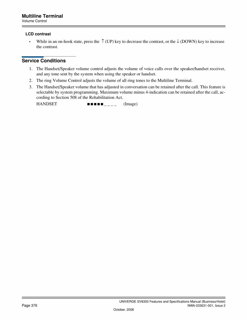
UNIVERGE SV8300 Features and Specifications Manual (Business/Hotel)Page 376 NWA-033631-001, Issue 2
October, 2008
Multiline TerminalVolume Control
LCD contrast
• While in an on-hook state, press the ↑ (UP) key to decrease the contrast, or the ↓ (DOWN) key to increase the contrast.
Service Conditions
1. The Handset/Speaker volume control adjusts the volume of voice calls over the speaker/handset receiver,and any tone sent by the system when using the speaker or handset.
2. The ring Volume Control adjusts the volume of all ring tones to the Multiline Terminal.
3. The Handset/Speaker volume that has adjusted in conversation can be retained after the call. This feature isselectable by system programming. Maximum volume minus 4-indication can be retained after the call, ac-cording to Section 508 of the Rehabilitation Act.
HANDSET _ _ _ _ (Image)

UNIVERGE SV8300 Features and Specifications Manual (Business/Hotel)NWA-033631-001, Issue 2 Page 377
Multiline Terminal Attendant Position
Multiline Terminal Attendant Position
General Description
A Multiline Terminal with LCD can be programmed to function similar to an Attendant position. This Atten-dant position has limited access to Attendant related features and functions and can be substituted where an At-tendant is required but an Attendant Console is not necessary. When a DSS/BLF console is associated with thisAttendant Multiline Terminal, enhanced operation is available.
Station Application
All Multiline Terminals with LCD.
Operating Procedure
Answering and transferring an incoming Analog CO Line call
With an incoming call in progress (DDD, FX, or WATS line key LED is flashing, C.O. ring is heard):
1. Press the flashing line key or the Answer key.
2. The First available LOOP key LED lights steady green. Incoming indication stops. The LCD shows thetrunk name and number.
3. Press the Transfer key and dial the station number to be transferred to, or press the desired DSS key. TheLCD shows the called station number.
4. Press the RLS key or go on-hook.
To Hold a call
With a call in progress:
1. Press the Hold key. The LOOP key flashes green.
2. Go on-hook or press the RLS key.
To retrieve a held call
1. Go off-hook.
2. Press the flashing LOOP key. The LED key indication goes to steady green.
3. Converse.
To set/cancel Message Waiting
1. Press the MW key on the DSS/BLF console to enter the Message Wait mode.
2. Press the associated DSS key for the desired station. The associated LED lights steady green for set Mes-sage Waiting or extinguishes when Message Waiting is canceled.
3. Press the MW key to return to the normal DSS mode.
To set/cancel Do Not Disturb
1. Press the DND key on the DSS/BLF console to enter the Do Not Disturb mode.

UNIVERGE SV8300 Features and Specifications Manual (Business/Hotel)Page 378 NWA-033631-001, Issue 2
Multiline Terminal Attendant Position
2. Press the applicable DSS key for the desired station. The associated LED lights steady green when Do NotDisturb is set and extinguishes when Do Not Disturb is canceled.
3. Press the DND key to return to the normal DSS mode.
To set/cancel Night Service
1. Press the NT key on the DSS/BLF Console.
OR
Dial the Night Service set/cancel code when off-hook on the primary extension.
Answering an Operator call
1. Press the OPE key. The associated LED lights steady green. The LCD will display either the trunk nameand number or the station name and number.
2. Converse.
Service Conditions
1. Transfer of calls is possible with the Transfer key.
2. Answering of calls is possible using the Answer key or by direct line key selection.
3. Normal internal call operation is available using the station's primary extension, a secondary extension, ora software line appearance.
4. A DSS/BLF Console can be associated with the Attendant Multiline Terminal, and its keys can be assignedas Direct Station Selection (DSS) keys and used in conjunction with the RLS key.
5. When the DSS/BLF Console is assigned for use with the Multiline Terminal, the unit can be provided witha Message Wait (MW) key, a Do Not Disturb (DND) key, and a Night Transfer (NT) key. Using the MWkey converts the DSS/BLF Console into a Message Wait Console. Using the DND key converts the DSS/BLF Console into a Do Not Disturb console. Using the NT key places the associated tenant into night mode.Only one of these can be accessed at one time.
6. An RLS key can be assigned on the Multiline Terminal's line keys.
7. Use of the RLS key during a call in progress will terminate that call, unless a transfer is in progress, in whichcase the transfer occurs. (The RLS key acts the same as going on-hook).
8. The associated LED for MW, DND or NT on the DSS/BLF Console will light steady green when in use,and be off when canceled.
9. The associated LED for each station assigned MW or DND is steadily lit green while it is set, but is dis-played only when the Multiline Terminal user activates the Message Wait mode or Do Not Disturb mode.
10. Direct trunk line appearances may be assigned to the Attendant Multiline Terminal. Operation is the sameas on normal Multiline Terminals. Attendant Console style operation is not available with Trunk DirectAppearances.
11. For operator calls from Tie lines, the outside party must dial a virtual line number associated with an ATTposition.
12. An NT key may be assigned to a Multiline Terminal when no master Attendant Console or no station forDay/Night Mode Change by Station Dialing is provided by the tenant.
13. When a station has been in Line Lockout, the associated LED on the DSS Console flashes red at 30 ipm.
14. While Attendant Position is in night mode, call termination to Attendant Position can be restricted. Or whenNight Service is assigned to Attendant Position, calls can be transferred to the night station.

UNIVERGE SV8300 Features and Specifications Manual (Business/Hotel)NWA-033631-001, Issue 2 Page 379
Multiline Terminal Attendant Position
• This feature is also operable for the following stations.
a. Virtual station for other than ICI/OPR key in Attendant Position
b. Multiline Terminal my-line, SLT, PS
• Conditions of call terminationThis feature is available when calls are terminated directly from a station/trunk, or forwarded by CallForwarding - All Calls/Busy Line/No Answer or Do Not Disturb to Attendant Position in night mode.
• Priority when both Night Service and other Call Forward service are setWhen Night Service and Call Forward service by Call Forwarding -All Calls, Do Not Disturb, UCD orStation Hunting are set in night station, call termination is restricted or call transfer are operated accord-ing to the conditions of Night Service.
• Display of transfer destination when a call is transferred by Night Service
a. Transferring party is Attendant Position, incoming call from a stationService Type: None Intermediate station number: None
b. Transferring party is Attendant Position, incoming call from a trunkService Type: None Intermediate station number: OPE

UNIVERGE SV8300 Features and Specifications Manual (Business/Hotel)Page 380 NWA-033631-001, Issue 2
October, 2008
Multiple Language Display
Multiple Language Display
General Description
A language displayed in the LCD of a Digital Multiline Terminal and Attendant Console can be selected on aper-station basis or on a per-operator console basis. The available languages are the same as used on a system-wide basis.
Station Application
Multiline Terminals and Attendant Consoles (SN716 DESKCON).
Operating Procedure
No manual operation is required.
Service Conditions
1. For Digital Multiline Terminal, a display language is set with system data for each station. If this data is notset, the system-wide setting is used. Available languages are:
English, French, Spanish, Portuguese, German, Italian, Dutch, French (EU), Spanish (EU), Portuguese (EU), Swedish, Danish, Catalan
2. Table below shows whether the language of LCD display item for each Digital Multiline Terminal is select-able from multiple languages.
X: Selectable—: Not selectable
Display item Selectable Remark
Time display X Selectable on per-station basis
Service type display such as “CF ALL” X Selectable on per-station basis
Trunk type display such as “DDD” X Selectable on per-station basis
Soft key X Selectable on per-station basis
Explanation of the soft key HELP X Selectable on per-station basis
Dterm Series i volume display X Selectable on per-station basis
Rows 1 and 2 on the IP Multiline Terminal log-in screen
— Selectable on System-wide basis
Soft keys on the IP Multiline Terminal log-in screen(Row 3 on the log-in screen)
— English only
Currency unit for ISDN charge notification —Selectable between $ and blank by System-wide basis
Reason for absence of calling number notification — Selectable by System-wide basis
Display related to Voice mail — Depending on Voice Mail equipment
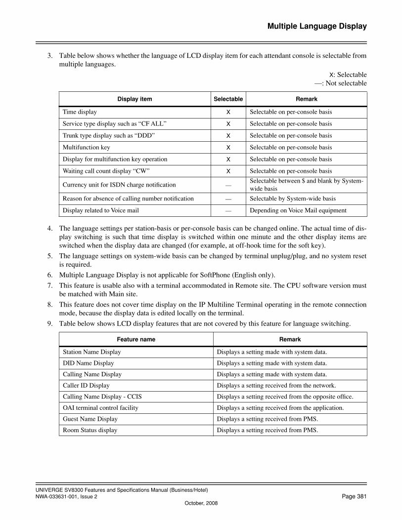
UNIVERGE SV8300 Features and Specifications Manual (Business/Hotel)NWA-033631-001, Issue 2 Page 381
October, 2008
Multiple Language Display
3. Table below shows whether the language of LCD display item for each attendant console is selectable frommultiple languages.
X: Selectable—: Not selectable
4. The language settings per station-basis or per-console basis can be changed online. The actual time of dis-play switching is such that time display is switched within one minute and the other display items areswitched when the display data are changed (for example, at off-hook time for the soft key).
5. The language settings on system-wide basis can be changed by terminal unplug/plug, and no system resetis required.
6. Multiple Language Display is not applicable for SoftPhone (English only).
7. This feature is usable also with a terminal accommodated in Remote site. The CPU software version mustbe matched with Main site.
8. This feature does not cover time display on the IP Multiline Terminal operating in the remote connectionmode, because the display data is edited locally on the terminal.
9. Table below shows LCD display features that are not covered by this feature for language switching.
Display item Selectable Remark
Time display X Selectable on per-console basis
Service type display such as “CF ALL” X Selectable on per-console basis
Trunk type display such as “DDD” X Selectable on per-console basis
Multifunction key X Selectable on per-console basis
Display for multifunction key operation X Selectable on per-console basis
Waiting call count display “CW” X Selectable on per-console basis
Currency unit for ISDN charge notification —Selectable between $ and blank by System-wide basis
Reason for absence of calling number notification — Selectable by System-wide basis
Display related to Voice mail — Depending on Voice Mail equipment
Feature name Remark
Station Name Display Displays a setting made with system data.
DID Name Display Displays a setting made with system data.
Calling Name Display Displays a setting made with system data.
Caller ID Display Displays a setting received from the network.
Calling Name Display - CCIS Displays a setting received from the opposite office.
OAI terminal control facility Displays a setting received from the application.
Guest Name Display Displays a setting received from PMS.
Room Status display Displays a setting received from PMS.

UNIVERGE SV8300 Features and Specifications Manual (Business/Hotel)Page 382 NWA-033631-001, Issue 2
October, 2008
Music On Hold
Music On Hold
General Description
This feature plays music when a line is placed on hold. Music is provided by a circuit blade memory chip or alocal music source, such as a CD player or a radio.
Station Application
All stations.
Operating Procedure
No manual operation is required.
Service Conditions
1. Music may be played in three different cases: Analog CO Lines, Tie Lines, and internal Station-to-Stationcalls. The same source can be used for all three.
2. If an external music source is desired, it must be locally provided. Refer to the System Hardware Manualfor installation instructions.
3. Any of the following can be selected as the Music On Hold source:
• CPU provides the following eight synthesized melodies: Menuet (default setting), Nocturne, For Elise, The Maiden’s Prayer, When the saints go marching in,Amaryllis, Spring (from Four Seasons), Ich bin ein Musikante
• Hold tone
• External source: tuner, tape deck, CD player, etc. connecting via CPU
• Internal Recorded Message
4. IP Multiline Terminal uses only one synthesized melody (For Elise), built into an IP adapter unit.
5. Attendant operations resulting in Music On Hold being played include the following:
• When incoming calls to the Attendant are answered and the Attendant presses the HOLD key or dialsan extension number, the held party receives Music On Hold.
• When the Attendant camps on a call to a busy station, the calling party is connected to Music On Holduntil the called party answers or the Attendant reenters the switched loop.
6. When a station user in a two-party connection places the second party on hold, the second party is connectedto Music On Hold.
7. A maximum of ten Music On Hold input sources can be assigned. Each Music Source must be assigned toa different tenant.
8. Hold tone of SIP Multiline Terminal is replayed on the terminal side. Even if Internal Hold Tone is assignedby system data, the operation of SIP Multiline Terminal is same as that when internal holding tone is as-signed.
UNIVERGE SV8300 Features and Specifications Manual (Business/Hotel)NWA-033631-001, Issue 2 Page 383
October, 2008
Night ServiceAttendant Night Transfer
Night Service
General Description
This feature provides a variety of methods for handling incoming calls when the system is in night mode. Theseinclude:
• Attendant Night Transfer
• Call Rerouting
• Choice of Night Service
• Day/Night Mode Change by Attendant Console
• Day/Night Mode Change by Station Dialing
• Day/Night Mode Change by System Clock
• Night Connection - Fixed
• Night Connection - Flexible
• Trunk Answer Any Station (TAS)
• Overflow for TAS Queue
• Queue Limit for TAS
Attendant Night Transfer
General Description
When the Attendant Console is in Night Service, any operator directed calls (dial 0 calls) are automatically rout-ed to a programmed station.
Priority Calls and Off-Hook Alarms that terminate to an Attendant are also routed by this feature.
Station Application
All stations.
Operating Procedure
1. The calling party dials 0.
2. That call is automatically forwarded to the programmed station.
3. The calling party receives ringback tone.
4. Ringing signal is sent to the programmed station.
5. The programmed station goes off-hook, and the answered call can be transferred to another station or out-side party.

UNIVERGE SV8300 Features and Specifications Manual (Business/Hotel)Page 384 NWA-033631-001, Issue 2
October, 2008
Night ServiceAttendant Night Transfer
Service Conditions
1. This feature may be provided together with Night Connection Fixed or Night Connection Flexible to a pre-determined night station.
2. The predetermined night station for this feature can also be assigned as a night station for Night ConnectionFixed or Flexible.
3. If the night station is set for Call Forwarding, operator calls terminated to that station will be forwarded tothe designated station.
4. The night station can be assigned as a station in a Station Hunting group.
5. One night station per tenant is available in multiple tenant arrangements.
6. The night station can be assigned as a station in an Automatic/Uniform Call Distribution (UCD) group.
7. This operation is not applicable to Listed Directory Number (LDN) calls. For LDN calls, Night ConnectionFixed/Flexible or Trunk Answer Any Station (TAS) service is applicable.
8. Night stations can use the Call Hold, Call Transfer and Conference features, provided these features are pro-grammed into the night station's Class of Service.
9. Any calls to the Attendant (dial 0) during Night Service are routed to the night station.
10. Individual Attendant Access calls are not transferred to the night station assigned by Attendant Night Trans-fer.
11. If the Call Forwarding destination of a DID terminating station is an Attendant Console, and the Attendantis in night mode, the DID call can be transffered to the specified station.
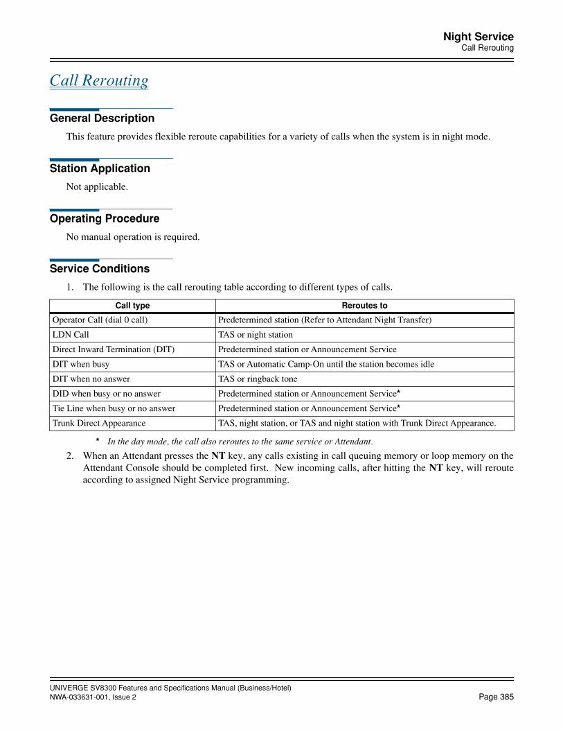
UNIVERGE SV8300 Features and Specifications Manual (Business/Hotel)NWA-033631-001, Issue 2 Page 385
Night ServiceCall Rerouting
Call Rerouting
General Description
This feature provides flexible reroute capabilities for a variety of calls when the system is in night mode.
Station Application
Not applicable.
Operating Procedure
No manual operation is required.
Service Conditions
1. The following is the call rerouting table according to different types of calls.
* In the day mode, the call also reroutes to the same service or Attendant.
2. When an Attendant presses the NT key, any calls existing in call queuing memory or loop memory on theAttendant Console should be completed first. New incoming calls, after hitting the NT key, will rerouteaccording to assigned Night Service programming.
Call type Reroutes to
Operator Call (dial 0 call) Predetermined station (Refer to Attendant Night Transfer)
LDN Call TAS or night station
Direct Inward Termination (DIT) Predetermined station or Announcement Service
DIT when busy TAS or Automatic Camp-On until the station becomes idle
DIT when no answer TAS or ringback tone
DID when busy or no answer Predetermined station or Announcement Service*
Tie Line when busy or no answer Predetermined station or Announcement Service*
Trunk Direct Appearance TAS, night station, or TAS and night station with Trunk Direct Appearance.
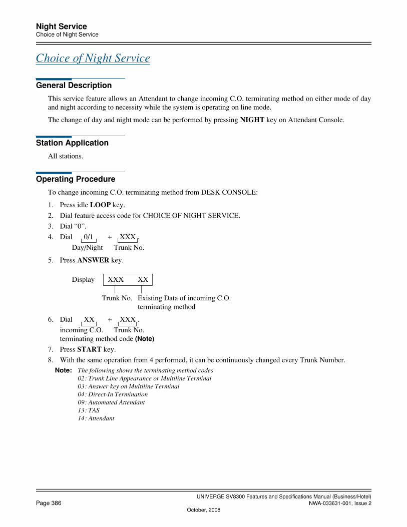
UNIVERGE SV8300 Features and Specifications Manual (Business/Hotel)Page 386 NWA-033631-001, Issue 2
October, 2008
Night ServiceChoice of Night Service
Choice of Night Service
General Description
This service feature allows an Attendant to change incoming C.O. terminating method on either mode of dayand night according to necessity while the system is operating on line mode.
The change of day and night mode can be performed by pressing NIGHT key on Attendant Console.
Station Application
All stations.
Operating Procedure
To change incoming C.O. terminating method from DESK CONSOLE:
1. Press idle LOOP key.
2. Dial feature access code for CHOICE OF NIGHT SERVICE.
3. Dial “0”.
4. Dial 0/1 + XXX .
Day/Night Trunk No.
5. Press ANSWER key.
Display XXX XX
Trunk No. Existing Data of incoming C.O. terminating method
6. Dial XX + XXX .
incoming C.O. Trunk No.terminating method code (Note)
7. Press START key.
8. With the same operation from 4 performed, it can be continuously changed every Trunk Number.Note: The following shows the terminating method codes
02: Trunk Line Appearance or Multiline Terminal03: Answer key on Multiline Terminal04: Direct-In Termination09: Automated Attendant13: TAS14: Attendant
UNIVERGE SV8300 Features and Specifications Manual (Business/Hotel)NWA-033631-001, Issue 2 Page 387
October, 2008
Night ServiceChoice of Night Service
Service Conditions
1. Incoming C.O. terminating method can be changed every one C.O. Trunk.
2. Changing incoming C.O. terminating method is only valid when Attendant Console is idle.If an incoming C.O. call appears on Attendant Console while changing incoming C.O. terminating method,the incoming C.O. call is being queued on Call Waiting.
3. It is not possible to change incoming C.O. terminating method from plural Attendant Console at the sametime.
4. Changing incoming terminating method to available even during NIGHT key is pressed.
UNIVERGE SV8300 Features and Specifications Manual (Business/Hotel)Page 388 NWA-033631-001, Issue 2
October, 2008
Night ServiceDay/Night Mode Change by Attendant Console
Day/Night Mode Change by Attendant Console
General Description
This feature provides activation of DAY/NIGHT Mode Change by pressing a predetermined key from the At-tendant Console.
Station Application
Attendant Console
Operating Procedure
To change Day to Night mode from SN716 DESKCON
1. Press Night key. Night lamp will be lit.
To change Night to Day mode from SN716 DESKCON
1. Press Night key when Night lamp is lit. Night lamp will be off.
Service Conditions
1. This feature can be activated only by a master Attendant Console.

UNIVERGE SV8300 Features and Specifications Manual (Business/Hotel)NWA-033631-001, Issue 2 Page 389
Night ServiceDay/Night Mode Change by Station Dialing
Day/Night Mode Change by Station Dialing
General Description
This feature allows selected stations to activate a change from day mode to night mode by dialing a special code.
Station Application
All stations.
Operating Procedure
By dial access code
1. Go off-hook and receive dial tone.
2. Dial the DAY/NIGHT Mode Change feature access code followed by 1 for DAY mode/2 for NIGHT mode/3 for MODE-A mode/4 for MODE-B mode.
3. Restore the handset.
By function key on a Multiline Terminal
1. Go off-hook or press the Speaker key and receive dial tone.
2. Press the assigned feature access key.
3. Dial 1 for DAY mode/2 for NIGHT mode/3 for MODE-A mode/4 for MODE-B mode.
4. Restore the handset or press the Speaker key.
Service Conditions
1. This feature is assigned in the station's Class of Service.
2. If using a function key on a Multiline Terminal, the associated lamp will be lit when the tenant changes Daymode to another mode.
Night mode :Red lamp on
MODE-A mode:Red lamp flashing (60 ipm)
MODE-B mode :Red lamp flashing (120 ipm)
3. On a system basis, incoming trunk destination and trunk restriction class can be changed (depending uponprogramming) when the tenant or system is placed in Night Service.
4. This feature is only available for the tenant without a master Attendant Console.

UNIVERGE SV8300 Features and Specifications Manual (Business/Hotel)Page 390 NWA-033631-001, Issue 2
Night ServiceDay/Night Mode Change by System Clock
Day/Night Mode Change by System Clock
General Description
This feature provides automatic activation of DAY/NIGHT Mode Change by using System Clock.
Station Application
Not Applicable.
Operating Procedure
No manual operation is required.
Service Conditions
1. This feature can be assigned per tenant.
2. Both two kinds of mode (DAY/NIGHT) and four kinds of mode (Day/Night/Mode A/Mode B) are avail-able.
3. Schedule for mode change can be set by the system programming. A maximum of 8 patterns is available.To simplify the schedule setting, a default pattern can be designated.
4. The lamp control is provided, if Day/Night Mode Change key is assigned on Multiline Terminal/DSS con-sole.
5. This feature can be unavailable temporarily by setting the external keys.
6. This feature also allows to change two kinds of mode (Day/Night) of trunk restriction class at the same time.
7. It takes from 4 to 8 seconds to change the mode.
8. To avoid conflict in Day/Night mode setting, this feature should not be used with following services.
a. Day/Night Mode Change per tenant by access code/feature key
b. Day/Night Mode Change by external key
c. Day/Night Mode Change of tenant by Attendant Console
UNIVERGE SV8300 Features and Specifications Manual (Business/Hotel)NWA-033631-001, Issue 2 Page 391
Night ServiceTrunk Answer Any Station (TAS)
Trunk Answer Any Station (TAS)
General Description
This feature allows any station, other than one with incoming restrictions, to answer incoming calls when thesystem is in the night mode. When this feature is activated, incoming exchange network calls will activate acommon alert signal at the customer premises. By dialing a specified code, any station may answer the call andthen extend it to any other station by means of the Call Transfer feature.
Station Application
All stations.
Operating Procedure
To answer a Trunk Answer Any Station (TAS) call:
1. The TAS signal sounds.
2. Go off-hook and receive dial tone.
3. Dial the specified TAS feature access code.
OR
Press the specified TAS key (on a Multiline Terminal if provided).
4. Connection to the incoming call is completed.
Service Conditions
1. TAS service can be assigned to the following types of lines:
• Direct Distance Dialing (DDD)
• Foreign Exchange (FX)
• Wide Area Telephone Service (WATS)
• Common Control Switching Arrangement (CCSA)
• Direct Inward Dialing (DID) (available only for LDN calls)
• E&M Tie (available only for operator calls)
2. TAS indication can be provided on a per-tenant basis, and there can only be one per tenant.
3. Stations that may access TAS service are programmed in Class of Service.
4. Stations accessing TAS service must be in the same tenant group.
5. By dialing different access codes, stations can access other tenants' TAS service.
6. A LC or 2PGDAD (or built-in relay in CPU) blade is required to interface with the TAS equipment.
7. TAS Call termination to the Answer key on Multiline Terminals can be programmed on a per-system basis.

UNIVERGE SV8300 Features and Specifications Manual (Business/Hotel)Page 392 NWA-033631-001, Issue 2
October, 2008
Night ServiceNight Connection - Fixed
Night Connection - Fixed
General Description
This feature allows incoming calls normally terminated to the Attendant to reroute to a predetermined stationwhen the system is placed in Night Service.
Station Application
All stations, except fully restricted stations.
Operating Procedure
With an incoming call during Night Service:
1. The outside party hears ringback tone.
2. Ringing signal is sent to the night station.
3. The night station goes off-hook and answers the call. If necessary, the answered call can be transferred toanother station or outside party.
Service Conditions
1. Night Connection station can be assigned the following types of trunks:
• Direct Distance Dialing (DDD)
• Foreign Exchange (FX)
• Wide Area Telephone Service (WATS)
• Common Control Switching Arrangement (CCSA)
• Direct Inward Dialing (DID) (available only for LDN calls)
• Tie (available only for operator calls)
2. Each night station can be assigned multiple trunks.
3. A fully restricted station cannot be assigned as a night station.
4. If the night station to which an incoming call has been terminated is busy, the system can be programmedto provide one of the following choices on a per-trunk basis:
• Automatic Camp-On
• Trunk Answer Any Station
• Ringback tone.
5. If the night station does not answer after a predetermined time, the system can provide one of the followingoptions on a per-trunk basis:
• Trunk Answer Any Station
• Ringback tone.
6. The night station can be assigned to a Station Hunting Group.
7. The night station can be assigned to an Automatic/Uniform Call Distribution (UCD) group.

UNIVERGE SV8300 Features and Specifications Manual (Business/Hotel)NWA-033631-001, Issue 2 Page 393
October, 2008
Night ServiceNight Connection - Fixed
8. If the night station has set Call Forwarding, incoming calls terminated to that station will be forwarded tothe destination station.
9. If the night station has set Call Forwarding to the Attendant, this setting will be ignored and incoming callswill terminate to the night station.
10. Night stations can access Call Hold, Call Transfer, and Conference provided these features are programmedinto its Class of Service.
UNIVERGE SV8300 Features and Specifications Manual (Business/Hotel)Page 394 NWA-033631-001, Issue 2
October, 2008
Night ServiceNight Connection - Flexible
Night Connection - Flexible
General Description
This feature provides incoming calls normally terminated to the fixed night station to be Call Forwarded to an-other station.
Station Application
All stations, except fully restricted stations.
Operating Procedure
Before placing the Attendant Console into Night Service, the Attendant sets Call Forwarding - All Calls fromthe fixed night station to the desired station.
Note: The Call Forwarding setting should be canceled when the tenant or system is changed back to the daymode.
Service Conditions
1. The Night Connection- Flexible station may be programmed from either the Attendant Console or the NightConnected - Fixed station.
2. Refer to the Call Forwarding Features and Specifications for more information.

UNIVERGE SV8300 Features and Specifications Manual (Business/Hotel)NWA-033631-001, Issue 2 Page 395
Night ServiceOverflow for TAS Queue
Overflow for TAS Queue
General Description
If the TAS call is not answered by predetermined time, the call will be forwarded to predetermined station/At-tendant Console/Announcement Service.
Station Application
Not applicable.
Operating Procedure
No manual operation is required.
Service Conditions
1. The target to be forwarded can be assigned per tenant and mode (Day/Night/Mode-A/Mode-B).
2. When both the target to be forwarded and the intermediate station are assigned by system programming,this feature is provided.
3. No answer timer can be assigned in 4-second increments. (default value: 28 - 32 seconds)
4. When the TAS call is forwarded to the predetermined station;
a. If the predetermined station is set Call Forwarding - All Calls or Split Call Forwarding - All Calls, the call is forwarded to another destination.
b. If the predetermined station is set Call Forwarding - Busy Line or Split Call Forwarding - Busy Lineand busy, the call is forwarded to another destination.
c. If the predetermined station that has set Call Forwarding - No Answer or Split Call Forwarding - NoAnswer, the call is forwarded to another destination.
d. If the predetermined station that is in Station Hunting group and busy, the call is forwarded to anotherstation within the group.
e. If the predetermined station that has set Do Not Disturb, the call is not forwarded.
5. When the TAS call is forwarded to the Announcement Service;
a. The voice message is sent to the call automatically and repeatedly.
b. If the Voice Response System (VRS) is not accommodated to the system, the TAS call is notforwarded.
6. The TAS call can be forwarded to the Voice Mail (UMS8000 Mail, MCI). In this case, "No answer" andintermediate station assigned by system programming is sent to the Voice Mail.
7. When the TAS call is forwarded to Multiline Terminal or Attendant Console, the LCD displays "CF NANS"and intermediate station number.
8. When the TAS call is forwarded to the predetermined station or Attendant Console, the call is added to thePeg Count, as number of the transferred call to the predetermined station/Attendant Console by Call For-warding - No Answer. When The TAS call is forwarded to the Announcement Service, the call is not count-ed.

UNIVERGE SV8300 Features and Specifications Manual (Business/Hotel)Page 396 NWA-033631-001, Issue 2
Night ServiceQueue Limit for TAS
Queue Limit for TAS
General Description
When a DID call is converted to TAS and the number of using lines reaches queue limit, this feature providesthe system to restrict the next call terminating.
Station Application
Not applicable.
Operating Procedure
No manual operation is required.
Service Conditions
1. The number of queue limit can be assigned per tenant and mode (Day/Night/Mode-A/Mode-B).
2. When the call terminating is restricted by queue limit, the following process depends on kind of trunk.
3. When the call terminating is restricted by queue limit, the call can be forwarded to the predetermined sta-tion.
a. When the predetermined station is set Call Forwarding - All Calls or Split Call Forwarding - All Calls, the call is forwarded to another destination.
b. When the predetermined station is set Call Forwarding - Busy Line or Split Call Forwarding - BusyLine and busy, the call is forwarded to another destination.
c. When the predetermined station that has set Call Forwarding - No Answer or Split Call Forwarding -No Answer, the call is forwarded to another destination.
d. When the predetermined station that is in Station Hunting group and busy, the call is forwarded toanother station within the group.
e. When the predetermined station that has set Do Not Disturb, the call is not forwarded and restricted.
4. When the call terminating is restricted by queue limit, the call can be forwarded to the Attendant Console.
5. When the call terminating is restricted by queue limit, the call can be forwarded to the Announcement Ser-vice.
a. The voice message is sent to the call automatically and repeatedly.
b. When the Voice Response System (VRS) is not accommodated to the system, the call is restricted.
Kind of trunk Restriction process
DID Busy tone from PBX
LD/OD/DTI Busy tone from PBX
ISDN Busy tone from PSTN
CCIS Busy tone from originate PBX
Caller ID (COT) Ring back tone from PSTN
UNIVERGE SV8300 Features and Specifications Manual (Business/Hotel)NWA-033631-001, Issue 2 Page 397
Night ServiceQueue Limit for TAS
6. When the call terminating is restricted by queue limit, the call can be forwarded to the Voice Mail(UMS8000 Mail, MCI).
7. When the call is restricted by queue limit, the call is added to the Peg Count, as the number of incomingcalls terminated to busy tone.

UNIVERGE SV8300 Features and Specifications Manual (Business/Hotel)Page 398 NWA-033631-001, Issue 2
Off-Hook Alarm
Off-Hook Alarm
General Description
This feature allows a station user to call the Attendant, or a designated station, by simply staying off-hook fora programmed period of time. The calling number is automatically displayed at the Attendant Console, or thedesignated station if equipped with an LCD.
Station Application
All stations.
Operating Procedure
1. Lift the handset and stay off-hook.
2. After a predetermined time elapses (30 seconds as set in default), the call will terminate at the AttendantConsole or a designated station.
3. The calling station number will be displayed at the Attendant Console when answered.
Service Conditions
1. The predetermined timing interval of 4-32 seconds in 4 second increments is programmable through the PCPCPro or Customer Administration Terminal (CAT).
2. The station assigned as a terminating station of each Off-Hook Alarm group can be a member of a huntinggroup.
3. This feature is assigned on a station basis for origination of Off-Hook Alarm and on a tenant basis for thedestination assignment.
4. The Attendant Console can answer by pressing the EMG key, which must be assigned by the PCPro orCAT. Answering by the Answer key will not give priority to the Off-Hook Alarm.
5. The designated station, if allowed, can set Call Forward-All Calls and Call Forward-Busy. The Off-HookAlarm will follow the Call Forward setting.
UNIVERGE SV8300 Features and Specifications Manual (Business/Hotel)NWA-033631-001, Issue 2 Page 399
Off-Premises Extensions
Off-Premises Extensions
General Description
This feature allows the connection of a single line telephone in an off-premises location. The connection to theOff-Premises Extension can be through direct copper or through the local telephone company.
Station Application
Single Line Stations.
Operating Procedure
Normal operating procedures apply.
Service Conditions
1. A DIOP blace is required for connection of Off-Premises Extensions. The CD-4DIOPA/B is a 4-circuitblade.
2. The maximum loop resistance for an Off-Premises Extension is 1500 Ω, including the resistance of the tele-phone.
3. Message Waiting is not available for Off-Premises Extensions.
4. Disconnect supervision is not available on Off-Premises Extensions.
UNIVERGE SV8300 Features and Specifications Manual (Business/Hotel)Page 400 NWA-033631-001, Issue 2
October, 2008
Operator Monitoring (For Australia)
Operator Monitoring (For Australia)
General Description
This service feature allows the operator at an Attendant to monitor the speech by pressing SC key in a casewhere the operator has encountered line busy when the operator has called a station.
Also, if the operator presses BV key while monitoring the call, the operator can bridge into the connection forbusy verification.
Operating Procedure
1. Attendant dials the station number.
2. Attendant receives Busy Tone.
3. Attendant presses SC key.
4. Connection between ICT and station or between station and station is monitored.
5. The bridged-in station receives Monitoring Tone. (Monitoring Tone sending service must have been set bythe command concerned.)
6. If Attendant presses RLS key, monitoring discontinues and Monitoring Tone stops.
7. If station or Trunk party goes on-hook, Reorder Tone is sent out also to Attendant.
8. If Attendant presses BV key while monitoring is in progress, a bridge-in call for busy verification is estab-lished.
Service Conditions
1. The calls that can be monitored are limited to station - trunk call and station - station call. If SC key ispressed in trunk - trunk call, it is ineffective.
2. If BV key is pressed while monitoring is in progress, a three-way connection is established.
3. If CFTs are all busy, press of SC key is ineffective.
4. If station or trunk party goes on-hook while monitoring is in progress, Reorder Tone is also connected toAttendant.
5. On Digital Multiline Terminal, “MON” is displayed as the indication of monitoring.
UNIVERGE SV8300 Features and Specifications Manual (Business/Hotel)NWA-033631-001, Issue 2 Page 401
October, 2008
Open Application Interface (OAI)
Open Application Interface (OAI)
General Description
Provides a computer-to-PBX interface, allowing a computer to control the function of the system. The systemcan be customized to accommodate most customer applications. Application software can be provided by anoutside software house, or a customer.
Operating Procedure
For operating procedures, see the individual OAI features.
Note: For more detailed information, consult the manuals for each individual OAI feature.
Service Conditions
1. This feature requires the following hardware/software:
• Ethernet blade
• APM Platform Software Rel FD 600C
• OAI Application FD 600C (Specific Application Software)
• OAI Computer
2. If the host computer goes off line for any reason, all OAI features will be unavailable.
3. Up to 24 digits of the calling subscriber’s number for Automatic Identification (ANI) can be sent out to theOAI Computer by system programming.
4. This feature supports TAPI 2.1.
5. Station numbers may be up to 5 digits long. Available numbers are 0 to 9, “*”, and “#”.Note that the number of digits depends on the OAI application software.
6. Attendant Console and ISDN terminal do not support the monitor.
7. Delete PBX station number after deleting station information such as SMFR. SSFR, and SSFM setting in-formation on the application side.
8. The backup function of ACF when the external OAI computer is out of service.
9. Free Location Facility (FLF) is available.
10. Up to four applications can be used per system.
UNIVERGE SV8300 Features and Specifications Manual (Business/Hotel)Page 402 NWA-033631-001, Issue 2
October, 2008
Pad Lock
Pad Lock
General Description
This feature temporarily restricts telephones from making unauthorized calls by dialing special access codewhen station users are away from their seats.
Station Application
Conditions of operating terminals are following.
If operate Pad Lock after change ID code class per station
<Applicable Terminals>
Single Line Telephone
Multiline Terminal (Note)
PSNote: From My Line only.
<Inapplicable Terminals>
Attendant Console
ISDN Terminal
Operating Procedure
To set Pad Lock
1. Lift the handset and receive dial tone.
2. Dial the access code for Station Authorization Code, and receive Service Set Tone if programmed.
3. Enter Station Authorization Code.
4. If the code is right, Dial Tone will be heard. (If the code is not right, Reorder Tone will be heard.)
5. Dial access code to set Room Cutoff.
6. Service Set Tone will be heard.
7. Restore handset.
To cancel Pad Lock
1. Lift the handset and receive dial tone.
2. Dial the access code for Station Authorization Code, and receive Service Set Tone if programmed.
3. Enter Station Authorization Code.
4. If the code is right, Dial Tone will be heard. (If the code is not right, Reorder Tone will be heard.)
5. Dial access code to reset Room Cutoff.
6. Service Set Tone will be heard.
7. Restore handset.
UNIVERGE SV8300 Features and Specifications Manual (Business/Hotel)NWA-033631-001, Issue 2 Page 403
Pad Lock
To set and change Station Authorization Code
1. Lift the handset and receive dial tone.
2. Dial the access code for Station Authorization Code.
3. Enter the old Station Authorization Code and then new Station Authorization Code.(Note 1)
4. Service Set Tone will be heard.
5. Restore handset.
Note 1: Enter the old Station Authorization Code, new Station Authorization Code and then new Station Autho-rization Code again.
- If the old Station Authorization Code is not matched, Reorder Tone will be heard.
- If the first entered new Station Authorization Code and second new one are not matched, ReorderTone will be heard.
- The digit of Station Authorization Code is set by the system data per system.
- Available ID code number is O to 9, *, and #.
Service Conditions
1. This feature restricts telephones from making C.O.outgoing calls and/or terminating calls from C.O.trunks,stations, and Attendant. Stations in Pad Lock status are able to place Station-to-Station calls and outgoingcalls using Attendant assisted calling.
2. If the station under Pad Lock status dials a Analog CO Line access code, the station is rerouted to one ofthe following:
a. Reorder Tone
b. Attendant
3. Calls to stations in Pad Lock status will receive reorder tone or, on a tenant basis, can be assigned to transferto the Attendant.
4. The feature access code for Station Authorization Code and Room Cutoff can be one to four digits.
5. About Authorization Code Limitations, refer to Authorization Code Features and Specifications.
6. Pad Lock status will continue unless it is cancelled.
7. The number of digits of Station Authorization Code is fixed on any digit from one to eight in system pro-gramming.
8. Station Authorization Code can be set per station number and changed from each station of which servicerestriction class is set allowed.
9. Station Authorization Code should be set at least once. (Default value is “NONE”. However, this feature isnot available when the assigned value is “NONE”.)
10. When setting Station Authorization Code for the first time, Station Authorization Code should be set 0 forthe number of its digits (up to 8 digits).
11. When entering Station Authorization Code from a Digital Multiline Terminal (with LCD to set or cancelPad Lock on change the Station Authorization Code), masking of the code by asterisk (*) is available if de-sired.
12. Station Authorization Code can be displayed, changed or cleared from PCPro.
13. If the digit of Station Authorization Code is changed after starting system operation, each Station Authori-zation Code should be cleared from PCPro, change the digit, then set Station Authorization Code again.

UNIVERGE SV8300 Features and Specifications Manual (Business/Hotel)Page 404 NWA-033631-001, Issue 2
Pad Lock
14. Service Restriction Class can be set per station and assigned in the system data from PCPro.
15. When in Pad Lock status, the station Class of Service cannot be changed to allow C.O.outgoing calls, byentering Authorization Code or Station Authorization Code. Otherwise, it is available when Pad Lock iscancelled.
16. When Pad Lock feature is used in the system, the Hotel/Motel Room Cutoff feature should not be used toavoid operational problems.
17. Station Authorization Code used in this feature can be output to SMDR as same as Authorization Code.

UNIVERGE SV8300 Features and Specifications Manual (Business/Hotel)NWA-033631-001, Issue 2 Page 405
PC Programming
PC Programming
General Description
The SV8300 PC Programming (herein after “PCPro”) is a personal computer that provides an interface to thePBX via the system’s CPU blade. The PCPro PC must have the PCPro program properly installed to commu-nicate with the PBX. PCPro is required for system software registration and activation.
PCPro is a Graphical User Interface (GUI) program that provides an efficient method to manipulate the PBXdatabase. This program contains extensive help files, Usage Wizards and Tool Tips, with hyperlinks imbeddedin the text. The hyperlinks provide quick access to the appropriate Add-In modules. Add-In modules provide auser friendly intuitive method to customize the PBX database.
Station Application
Not applicable.
Operating Procedure
Refer to the SV8300 PC Programming Manual.
Service Conditions
Operating Environments and Conditions
1. Operating environment of PC
• Common Operating Environment
Item Specification
Recommended CPU • Refer to <OS-Specific Operating Environments>
Hard disk • 1GB of free disk space minimum
Monitor • 1,024×768 dots or more, 16-bit colors (65,536) at least
CD-ROM drive • Required to install the program
Interface • 10BASE-T/100BASE-TX
Hardware connection to the Main Unit • IP connection / RS-232C direct connection / Modem Con-nection
Mouse • Mouse, or equivalent pointing device
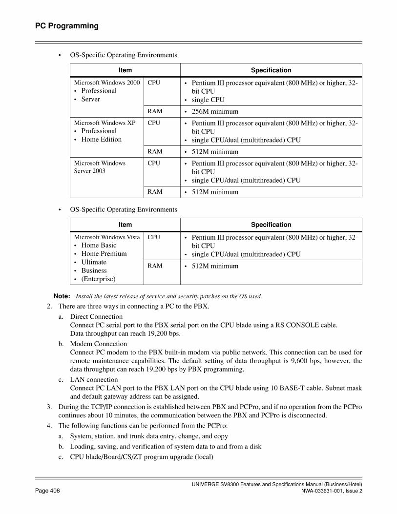
UNIVERGE SV8300 Features and Specifications Manual (Business/Hotel)Page 406 NWA-033631-001, Issue 2
PC Programming
• OS-Specific Operating Environments
• OS-Specific Operating Environments
Note: Install the latest release of service and security patches on the OS used.
2. There are three ways in connecting a PC to the PBX.
a. Direct ConnectionConnect PC serial port to the PBX serial port on the CPU blade using a RS CONSOLE cable.Data throughput can reach 19,200 bps.
b. Modem ConnectionConnect PC modem to the PBX built-in modem via public network. This connection can be used forremote maintenance capabilities. The default setting of data throughput is 9,600 bps, however, thedata throughput can reach 19,200 bps by PBX programming.
c. LAN connectionConnect PC LAN port to the PBX LAN port on the CPU blade using 10 BASE-T cable. Subnet maskand default gateway address can be assigned.
3. During the TCP/IP connection is established between PBX and PCPro, and if no operation from the PCProcontinues about 10 minutes, the communication between the PBX and PCPro is disconnected.
4. The following functions can be performed from the PCPro:
a. System, station, and trunk data entry, change, and copy
b. Loading, saving, and verification of system data to and from a disk
c. CPU blade/Board/CS/ZT program upgrade (local)
Item Specification
Microsoft Windows 2000• Professional• Server
CPU • Pentium III processor equivalent (800 MHz) or higher, 32-bit CPU
• single CPU
RAM • 256M minimum
Microsoft Windows XP• Professional• Home Edition
CPU • Pentium III processor equivalent (800 MHz) or higher, 32-bit CPU
• single CPU/dual (multithreaded) CPU
RAM • 512M minimum
Microsoft Windows Server 2003
CPU • Pentium III processor equivalent (800 MHz) or higher, 32-bit CPU
• single CPU/dual (multithreaded) CPU
RAM • 512M minimum
Item Specification
Microsoft Windows Vista• Home Basic• Home Premium• Ultimate• Business• (Enterprise)
CPU • Pentium III processor equivalent (800 MHz) or higher, 32-bit CPU
• single CPU/dual (multithreaded) CPU
RAM • 512M minimum
UNIVERGE SV8300 Features and Specifications Manual (Business/Hotel)NWA-033631-001, Issue 2 Page 407
PC Programming
d. Remote System Upgrade
e. Key FD Setup
f. Graphical Configuration Report
g. Display of fault/fault cleared messages
h. On site or remote access to the system
i. Display and setting of system clock/calendar
j. Call Pickup / Station Hunting / UCD - Group
k. Least Cost Routing (LCR)
l. Numbering Plan
m. System Reset
n. Download of PS operation data
o. Traffic Measurement
p. Day/Night Mode Change Schedule
q. Assignment of LAN Interface Data
r. LEN Listup
s. Service Restriction
t. Speed Calling - System
u. Speed Calling - Station
v. Setting System Accommodation Data
w. System Data Listup
x. VoIPDB setting
y. Digit Conversion
5. If a station is assigned the following data, it is not possible to change the station’s port assignment:
a. STATION HUNTING Group
b. CALL PICKUP Group
c. UCD Group
6. The PCPro can make backup disks of system data.
7. The following changes cannot be made without initialization:
a. Addition of a Chassis
b. Addition of any AP (Application Processors)
c. Addition of Digital Multiline Terminal data port
8. The system clock/calendar is entered using a 24-hour clock, and the month, day and date.
UNIVERGE SV8300 Features and Specifications Manual (Business/Hotel)Page 408 NWA-033631-001, Issue 2
Periodic Time Indication Tone
Periodic Time Indication Tone
General Description
This feature provides a periodic tone to the station user who has made an outgoing call. This feature can beallowed or denied for each station.
Station Application
All stations.
Operating Procedure
No manual operation is required.
Service Conditions
1. This feature is allowed or denied in the stations' Class of Service assignment using PCPro or the CustomerAdministration Terminal (CAT). Additionally, this feature can be allowed or denied on a system basis forAnalog CO Line and Tie Lines.
2. The Periodic Time Indication Tone is 80 ms. in duration. The interval between tones is programmable from32 seconds to 724 seconds (180 seconds as set in default).
3. Outgoing calls initiated by the Attendant will not have this feature.

UNIVERGE SV8300 Features and Specifications Manual (Business/Hotel)NWA-033631-001, Issue 2 Page 409
Pooled Line Access
Pooled Line Access
General Description
A line key can be assigned to access Pooled Lines. Each line key will allow incoming, outgoing, or both-wayaccess to a trunk route.
Station Application
All Digital Multiline Terminals.
Operating Procedure
To originate a call on Pooled Lines
1. Go off-hook and select the Pooled Line key. The Virtual Line key is seized if it is available. If the VirtualLine key is not available, the Primary Extension is seized. If neither line is available, Pooled Line Accessis impossible.
2. Receive dial tone from a trunk in that Pooled Line's assigned trunk route.
3. Dial desired number.
To answer a call on Pooled Lines
1. Go off-hook and select the ringing line key.
2. Converse.
Service Conditions
1. When all trunks in the Pooled Line group are busy, no visual indication is provided on the associated linekey LED. However, a different line key can be assigned for this purpose when required.
2. A user on a Pooled Line can access Call Park, Call Transfer, Conference, and Station Speed Dialing. StationMessage Detail Recording will provide a record of calls made on a Pooled Line.
3. When all trunks in the Pooled Line are busy and access is attempted, busy tone is received.
4. If the system is designated as KF registration, this feature will not be available.
5. When originating a call on Pooled Lines, the Virtual Line key that is seized is the first idle extension foundby the key scanning program, starting at button number 1 (one) and counting up to the last line button as-signed. Care should be taken in determining the line button assignments on Digital Multiline Terminalswith Pooled Lines to prevent inadvertent (or undesired) selection of someone else's extension(s).

UNIVERGE SV8300 Features and Specifications Manual (Business/Hotel)Page 410 NWA-033631-001, Issue 2
October, 2008
Power Failure Transfer
Power Failure Transfer
General Description
This feature provides for specified trunks to be automatically connected to designated Single Line Telephonesin the event of AC power loss. It is normally used when the system is not equipped with reserve power.
Station Application
Single Line Telephones, Multiline Terminal w/Power Failure Adapter (DT330/DT730/DT750).
Operating Procedure
Operation is automatic upon loss of input power to the system.
Service Conditions
1. The COT blade has two Power Failure Transfer (PFT) circuits.When the system is in power failure operation, the PFT circuits automatically connect the trunks to theemergency telephones in the event of AC power failure.
2. When the Power Failure Transfer feature is activated, telephone service is limited to incoming calls and/oroutgoing calls through the serving C.O. The Power Failure Single Line Telephone must be compatible with the dialing scheme on the trunks, wheth-er rotary dial or Dual-Tone Multi-Frequency (DTMF) dialing.
3. When the system is in power failure operation, Direct Inward Dialing (DID), CCSA, Tie Line and DISAcalls cannot be received.
4. All calls in progress and/or established calls are lost when a power failure occurs.
5. When Single Line Telephones are used as the emergency telephones,
• The Single Line Telephones can be used during only the AC power failure. (They cannot be used during the normal operation.)
• When commercial power is restored, the system automatically initializes.However, the calls in progress and/or established calls on the emergency telephones are held until on-hook.
6. When Multiline Terminals are used as the emergency telephones,
• The Multiline Terminals have to be equipped with power failure adaptors.
• The Multiline Terminals can be commonly used for the emergency telephones and telephones duringnormal operation.
• When commercial power is restored, the system automatically initializes, dropping all calls in progress.(Enhancement from 8300 R2 Software)When DT300/DT700 series are used as emergency telephones, the calls in progress and/or establishedcalls on the emergency telephones are held until on-hook.
7. Power Failure Transfer (PFT) lines should not be wired to common bells, since these require outside powersources and therefore will not operate.
8. If the Central Office provides ground-start trunks, Single Line Telephones must be equipped with groundbuttons to complete calls over the exchange network.

UNIVERGE SV8300 Features and Specifications Manual (Business/Hotel)NWA-033631-001, Issue 2 Page 411
Priority Call
Priority Call
General Description
This feature allows the Attendant to answer a call before other calls, at the Attendant's discretion.
Station Application
All stations.
Operating Procedure
To initiate a Priority Call from any station
1. Lift the handset and receive dial tone.
2. Dial the Priority Call number.
To answer a Priority Call at the Attendant Console
1. The Attendant presses the designated Priority Call key.
Service Conditions
1. A Priority Call can be answered by pressing the Answer key, provided no other calls are waiting. If othercalls are waiting, the Priority Call must be answered by pressing the designated Priority Call key to be an-swered first.
2. The designated Priority Call key must be assigned using the PCPro or the Customer Administration Termi-nal (CAT).
3. Two Priority Call numbers can be assigned. Separate Priority Call keys must be assigned at the AttendantConsole.
4. The ability to place a Priority Call can be allowed or denied in Class of Service.
5. A Priority Call to an Attendant Console when the system is in night mode receives reorder tone.
6. When a station is assigned as the destination of a Priority Call and the station has set Call Forwarding, thePriority Call will follow the Call Forwarding setting.

UNIVERGE SV8300 Features and Specifications Manual (Business/Hotel)Page 412 NWA-033631-001, Issue 2
PrivacyDirect Privacy Release
Privacy
General Description
This feature restricts Digital Multiline Terminal users from pressing a busy line key and entering a conversationunless permitted by the Digital Multiline Terminal user currently on that line key or if the line key is assignedfor Direct Privacy Release.
Direct Privacy Release
General Description
This feature allows a station user with a secondary appearance of another extension in the system to access thatextension when it is being used by someone else. This feature allows for a simplified method for establishinga conference. In addition, this feature can be used to emulate PC dialing, where a single line extension connect-ed to a PC can appear on a Digital Multiline Terminal and be accessed by the Digital Multiline Terminal userafter the PC is completed dialing.
Station Application
All Digital Multiline Terminals.
Operating Procedure
Accessing an extension already in use (lit steady red) by someone else
1. Press the line key associated with the extension to be accessed. The associated line key changes to green,and the display shows a conference in progress (left side of display: CONF).
2. Inform parties of your presence and converse.
PC Dialing
(With desired communication program loaded and ready within the PC)
1. Initiate the dialing sequence in the communication program. Modem dials out on associated single line ex-tension.
2. After the modem has completed dialing, press the line key associated with the secondary appearance of thesingle line extension on the Digital Multiline Terminal.
3. On the PC, execute the command sequence to tell the modem to go on-hook.
4. Converse with called party when they answer.
Service Conditions
1. This feature can be allowed/denied to a Digital Multiline Terminal via Class of Service assignment.
UNIVERGE SV8300 Features and Specifications Manual (Business/Hotel)NWA-033631-001, Issue 2 Page 413
PrivacyDirect Privacy Release
2. This feature is allowed only when the extension to be accessed is in conversation with another extension ortrunk. This feature is denied when the extension to be accessed is listening to a system tone (busy tone,service set tone, internal ringback tone, etc.).
3. Access is denied to an extension that has a camp-on set to it or has been overridden via Executive Overrideor Attendant Override.
4. The ability to access a busy extension that is making an outside (trunk) call prior to being answered is de-pendent on proper setting of the maximum digit dialed assignment.
5. This feature is denied on an extension that has been placed on Call Hold by another extension or has placedanother party on Call Hold.
6. A station user can establish a three-party conference by pressing the busy line key, without using the pri-mary extension of the station.

UNIVERGE SV8300 Features and Specifications Manual (Business/Hotel)Page 414 NWA-033631-001, Issue 2
October, 2008
PrivacyManual Privacy Release
Manual Privacy Release
General Description
This feature allows a Multiline Terminal user to enter a conversation on a busy line key if the Multiline Terminaluser already in the conversation allows them by releasing Privacy.
Station Application
Multiline Terminals.
Operating Procedure
To activate Privacy Release with a call in progress:
1. Press the Conf key. The Conf LED flashes.
2. Another station with the same line appearance presses that line key.
3. Privacy on that line is released and a three-party Conference is in progress.
4. Repeat above procedure to establish a four-party Conference, if desired.
Service Conditions
1. When a line is busy and Manual Privacy Release has not been activated on that line, any attempt to accessthat line will result in busy tone.
2. Manual Privacy Release is available for Digital Multiline Terminals connected to any extension line key.
3. When a Digital Multiline Terminal user presses the Conf key, Privacy on the active line is released. If theConf key is pressed again or another party enters the connection, Privacy is reestablished.
4. After a third party enters the conversation, the Conf key can be pressed again. Privacy is released and afourth party is allowed to join the conversation by the same operating procedure.
5. Manual Privacy Release is activated only on a connection during which the Conf key is pressed. Once thestation releases the connection, Manual Privacy Release is canceled and Privacy is restored.
6. A station user can establish a three-party conference by pressing the busy line key, without using the pri-mary extension of the station.
UNIVERGE SV8300 Features and Specifications Manual (Business/Hotel)NWA-033631-001, Issue 2 Page 415
October, 2008
Private Lines
Private Lines
General Description
Only a C.O. trunk assigned to that specific station is seized when a station user originates an outgoing C.O. callor when an incoming C.O. call is terminated at the station designated by Direct-In-Termination. In this manner,stations and C.O. trunks are to be associated on a 1-to-1 basis.
Station Application
All Multiline Terminals and Single line Telephones.
Operating Procedure
No manual operation is required.
Service Conditions
1. Incoming and outgoing restriction assignments can be used to assure privacy.
2. The following features are available:
• Conference
• Delayed Ringing
• Station Message Detail Recording (SMDR)
• Call Transfer
• Call Park
• Call Hold
• Save and Repeat
• Last Number Redial
• Broker's Call
• Station Speed Dialing using feature keys
3. When an outgoing call is placed, System Speed Dialing cannot be used.
4. The LED associated with the line key will be lit red when the trunk is busy, and green when being used bythe station that selected that trunk.
5. For further information, refer to the Flexible Line Key Assignment, Flexible Ringing Assignment, andTrunk - Direct Appearance features.
6. This feature is valid for outgoing calls from a Single line Telephone or Digital Multiline Terminal.
7. For an outgoing call, multiple trunks can be designated per station so that one specific trunk can be selectedout of them for seizure.
8. The following are valid methods for making an outgoing call from a Private Line:
• Dialing the C.O. trunk access code
• Station/System Speed Dialing
• Least Cost Routing
UNIVERGE SV8300 Features and Specifications Manual (Business/Hotel)Page 416 NWA-033631-001, Issue 2
Private Lines
• Trunk Direct Appearance on a Digital Multiline Terminal
• Last Number Redial
9. Private Lines are not available when using Trunk Queuing-Outgoing and Timed Queue.
10. If a station uses a direct trunk line appearance on a Digital Multiline Terminal for an OG calling, the call isoriginated from the C.O. trunk corresponding to the key pressed.
11. Only C.O. (loop-start and ground-start) trunks and Tie Line trunks can be assigned as private lines.
12. If the designated trunk is busy, the system is able to hunt to the next trunk (following increasing trunk num-ber order). When the route number of the trunk differs from the route number of the original designatedtrunk, hunting stops and the caller receives busy tone.
13. If a station uses a secondary extension on a Digital Multiline Terminal for an OG calling, the designatedtrunk for the primary extension of that station is seized.
14. A designated trunk cannot be seized unless the route of the trunk access code is the same as the route of thattrunk.
15. In the case of an outgoing call from an Attendant Console or a tandem call, a trunk is seized normally, irre-spective of this feature.
16. An Account Code may be entered using a function key programmed for Account Code entry or AccountCode can be dialed on second dial tone.

UNIVERGE SV8300 Features and Specifications Manual (Business/Hotel)NWA-033631-001, Issue 2 Page 417
Property Management System Interface
Property Management System Interface
General Description
The system provides a data interface to a locally-provided Property Management System (PMS). This enablescommunication between the system and the PMS to provide computer control of Hotel/Motel features.
Major functions and their interactions are indicated below:
Station Application
Not applicable.
Operating Procedure
Operating procedures will vary with the locally-provided PMS.
Service Conditions
1. One Interface Port is provided for PMS.
2. The system sends information relating to the following features to the PMS upon request from the PMS:
• Do Not Disturb
• Room Cutoff
3. PMS interfaces is available as follow:
Built-in PMS on IP (CPU) PMS connection is provided via TCP/IP port on CPU
Service Conditions on Built-in PMS on IP
1. Ethernet blade is required.
2. When the Built-in PMS on IP is used, following functions can be operated only from the PMS:
• Check In/Check Out
Automatic Wake-up System PMS
Message Waiting System PMS
Automatic MW Lamp-off System PMS
Check In/Check Out System PMS
Direct Data Entry System PMS
Maid Status System PMS
Do Not Disturb System PMS
Room Cutoff System PMS
Room Status System PMS
Room Change/Room Swap System PMS
Message Registration System PMS
Guest Name Display System PMS

UNIVERGE SV8300 Features and Specifications Manual (Business/Hotel)Page 418 NWA-033631-001, Issue 2
October, 2008
Property Management System Interface
• Room Status
3. The use of the Hotel/Motel functions built in the CPU requires interaction with the PMS. On the PBX side,the status data necessary for implementing the functions is lost if system initialization occurs. In that case,the data needs to be restored by the recovery process from the PMS, upon request from the PBX.
4. The maximum lengths of the station number are six digits. The station number with seven-digit or longernumbers cannot be used.
5. There are two methods for billing control - by using the PMS or by using the SMDR. It must be selected bysystem data programming. It is not possible to use both methods per system.
6. If the communications with PMS are lost, some services will not be available. Since it takes 120 to 180 sec-onds for the PBX to recognize the communication error after it occurs, those services will be available dur-ing that time.
7. The interface conditions between PBX and PMS are listed below.
8. The CPU blade (in Remote Unit system, CPU blade in Main site) communicates with the PMS. In the com-munication settings of the PMS side, set the IP address of the CPU blade specified by system data to theaddress to be connected, and set the port number to 60050.
9. When the Built-in PMS on IP is used, only Maid/Room Status codes 1&2 can be dialed from the Guest Sta-tion. Maid/Room Status codes 3 thru 8 are NOT available.
Item Condition
Physical layer Ethernet
Connection layer The Ethernet packet format conforms to the DIX standard.
TCP/IP core protocol ARP, IP, ICMP, UDP, TCP
Socket interface Conforming to the 4.3BSD socket interface
Transport protocol TCP stream-type protocol
Application port number 60050 (fixed)
Number of connections 1
Client/serverServer: PBXClient: PMS
Transmission encoding 7-bit, ASCII code
Pseudo-normal condition1. At connection release2. Status monitoring text

UNIVERGE SV8300 Features and Specifications Manual (Business/Hotel)NWA-033631-001, Issue 2 Page 419
Property Management System Interface
Service Conditions on Printer connection
1. When the Built-in PMS on IP is used, below information regarding Hotel/Motel service can be automati-cally output to a Hotel/Motel Printer connected to an RS port of an CPU blade
• Automatic Waku-Up Set/Cancel
When Automatic Wake-Up is set/canceled from a guest station or an administrative terminal (FrontDesk Instrument, DSS Console, Attendant Console or PMS terminal), date and time, guest station num-ber and wake-up time are printed out. Setting/canceling station number or terminal type is also printedout when the feature is set or canceled from the administrative terminal.
• Automatic Wake-Up Result
When Automatic Wake-Up is executed, the result of the wake-up attempt is printed out (Start Ringing,Answered, No Answer, Busy or Incomplete).
• Do Not Disturb Set/Cancel
When Do Not Disturb is set or canceled from a guest station or an administrative terminal (Front DeskInstrument, DSS Console, Attendant Console or PMS terminal), date and time and guest station numberare printed out. Setting/canceling station number or terminal type is also printed out when the featureis set or canceled from the administrative terminal.
• Message Waiting Set/Cancel
When Message Waiting is set or canceled from an administrative terminal (Front Desk Instrument, DSSConsole, Attendant Console or PMS terminal), date and time, guest station number, and setting/cancel-ing station number (or terminal type) are printed out.
• Room Cutoff Set/Cancel
When Room Cutoff is set or canceled from an administrative terminal (Front Desk Instrument, DSSConsole, Attendant Console or PMS terminal), date and time, guest station number, and setting/cancel-ing station number (or terminal type) are printed out.
• Check In/Check Out Set/Cancel
When Check In/Check Out is set or canceled from a PMS terminal, date and time and guest station num-ber are printed out.
• PMS Interface Connected/Disconnected
When PMS interface is connected or disconnected, date and time of these events is printed out.
• Maid Status Change Result
When Maid Status is changed from a guest room station or an administrative terminal (Front Desk In-strument, DSS Console, Attendant Console or PMS terminal), date and time, guest station number,maid status number and maid ID are printed out.
• Immediate Printout of Call Detailed Record
At the end of a call, the call detailed records are printed out immediately, such as called number, callstart time, call duration, call charge, account code and authorization code. If the call record cannot beoutput to a printer due to some reasons, output information is stored in an CPU blade, and it is outputas the printer is ready. The number of calls that can be stored is 64 calls. When an overflow occurs, theoldest call record is discarded and call record of the latest 64 calls are stored. This information is deletedat initialization of the system or CPU.
2. Whether to print out the above information can be selected for each service by system data programming.
3. The maximum number of station number digits that can be printed is 6 when the Built-in PMS on IP is used.
4. The maximum allowable number of printer output queues is 64 (fixed) when the Built-in PMS on IP is used.If this number is exceeded, the older queues are deleted.

UNIVERGE SV8300 Features and Specifications Manual (Business/Hotel)Page 420 NWA-033631-001, Issue 2
October, 2008
Property Management System Interface
5. The maximum number of connectable printer is 1 per system.
6. The connectable RS port of CPU blade is RS1 or RS2 only when the Built-in PMS on IP is used.
7. On printer connection, RS port only in UNIT#1 can be used in 8300R1 software.In 8300R2 software or later, RS ports in UNIT#1/#2/#3 can be used.
8. The time information such as service setting time (year, month, day, hours, and minutes) is based on mainsite time. Main site time is used also when the time information is output for a station accommodated in aremote site.
UNIVERGE SV8300 Features and Specifications Manual (Business/Hotel)NWA-033631-001, Issue 2 Page 421
October, 2008
Remote Hold
Remote Hold
General Description
This feature allows a Multiline Terminal user and an attendant to hold it on the line button of transferred termi-nal, by pressing the Hold key.
Station Application
All Multiline Terminals and Attendant Consoles.
Operating Procedure
To set from Multiline Terminal
1. Multiline Terminal-A is talking with station/trunk party.
2. Press the Transfer key and dial the station number of Multiline Terminal-B.
a. Station/trunk party hears music on hold.
b. Digital Multiline Terminal-B is rung or notified call transfer by Voice Call.
c. The line button of Multiline Terminal-B is flashing to indicate the incoming transferred call.
3. Multiline Terminal-A presses the Hold key.
a. The ringing of Digital Multiline Terminal-B is stopped
b. The line button of Digital Multiline Terminal-B is flashing to indicate the call on hold.
To set from Attendant Console
1. The Attendant is talking with station/trunk party.
2. Dial the target station number.
3. The Attendant Presses the HOLD key.
To answer
Press the line button on Digital Multiline Terminal-B or other terminals that have the line button of Multi-line Terminal-B.
OR
From other stations, dial access code for Direct Call Pick-up and the station number of Multiline Terminal-B.
Service Conditions
1. This feature is provided according to Class of Service.
2. If the called terminal is Single Line Telephone or PS, this feature is not activated.
UNIVERGE SV8300 Features and Specifications Manual (Business/Hotel)Page 422 NWA-033631-001, Issue 2
October, 2008
Remote Hold
3. After setting Remote Hold, if the call is not answered for pre-assigned time, the original Multiline Terminal/the Attendant Console is recalled, even if the called Multiline Terminal is set Call Forwarding - No Answer.When the Attendant answers the recall, Remote Hold can be set again by pressing HOLD key.

UNIVERGE SV8300 Features and Specifications Manual (Business/Hotel)NWA-033631-001, Issue 2 Page 423
Remote System Upgrade
Remote System Upgrade
General Description
SV8300 provides Online Remote System Upgrade via IP network. The SV8300 downloads the CPU upgradeprogram from FTP server using PCPro. Immediate or scheduled changeover to the upgrade program is avail-able. It is also possible to change back to the previous program that was in use before the changeover (change-back).
Program Download
Program Download is executed on line by PCPro command, in two ways: immediate download and scheduleddownload. The PBX functions can be used as usual during the download process.
Program Changeover
Program Changeover is executed by PCPro command in three ways: automatic changeover, immediatechangeover and scheduled changeover. With the scheduled changeover method, it is possible to have thechangeover (and restart) executed at a specified time, e.g., during the midnight when the PBX is not used.
Version Matching
Version Matching is executed by PCPro command, as required. PBX copies the updated side to the outdatedside of MP Standby program, to match those program versions on line.

UNIVERGE SV8300 Features and Specifications Manual (Business/Hotel)Page 424 NWA-033631-001, Issue 2
Remote System Upgrade
MP Program Download (FTP) for Remote Site
This feature is extended for Remote Site system in the Remote Unit network. By command entry from PCProin the main site, the CPU program stored in the external FTP server is downloaded to the CPU of the remotesite. The downloaded program stored in the CPU is changed over to the existing working CPU program. TheFTP server can be located in the main site or in each remote site. If the remote site is operating in survival modedue to some reasons, the download by connecting PCPro to the remote site is also enabled.
Main UNIT orders main UNIT and Remote UNIT working together to download and changeover. FTP serverused for downloading can be assigned for each UNIT. (UNITs can share one FTP server, too.)

UNIVERGE SV8300 Features and Specifications Manual (Business/Hotel)NWA-033631-001, Issue 2 Page 425
Remote System Upgrade
And the download by connecting PCPro to the Remote UNIT is also enabled if the remote site is operating insurvival mode due to some reasons (bug, version mismatching etc.).
Station Application
Not applicable.
Operating Procedure
Refer to the Maintenance Manual for operation of Remote System Upgrade.
UNIVERGE SV8300 Features and Specifications Manual (Business/Hotel)Page 426 NWA-033631-001, Issue 2
Remote System Upgrade
Service Conditions
General Conditions
1. The call processing will stop only for the required time for program changeover, that is a reset time.
2. As the download protocol, “FTP (File Transfer Protocol)” is used.
3. As a FTP server, a PC must be prepared. With Windows2000 or WindowsXP, the attached IIS (InternetInformation Server) can be used. Note that some FTP including IIS cannot assign a port number used fordata transfer dynamically. In that case, after download is suspended or download is completed abnormally,it is not possible to retry to download until the port is released.
4. If the FTP server ID and password are not specified, anonymous login is used.
5. The download can be started in online mode, and the PBX remains on line throughout the download pro-cess. When the PBX changes over to the downloaded program, it is reset and then restarted.
6. Two TCP port numbers are used for transfer request and file transfer. (When the default TCP port number00021 is used, Port=00021 is used for transfer request and Port=00020 is for file transfer.)
7. The download execution status can be checked visually with the L0 lamp (green) of CPU blade.
• Downloading: Flash rapidly (240 IPM)
• Download complete: Light on
• Changeover complete: Light off
• Download failed/interrupted: Flash slowly (120 IPM)
• Version matching: Flash slowly (60 IPM)
• Version matching complete: Light off
8. If any error is detected during the restart process that follows the download, the system is automatically resetand then restarted with the program in the outdated side (the program that was in use before the download).This is called automatic changeback. The changeback can be carried out manually as well.
9. Download execution, immediate program changeover and version matching cannot be executed off line. Ifit is attempted to execute, “CODE NOT USED” is displayed. Reading the data and setting of the executiondate and time are possible in off line.
10. Program download or version matching cannot be executed during office data backup. If executed, WAIT,BUSY NOW is displayed. And also, the office data backup cannot be executed during the program down-loading or version matching. If Automatic Office Data Backup is executed, WAIT, BUSY NOW is dis-played and the backup of the day is stopped and will be executed on next day. Therefore, note that the timeof office data backup once a day need to be set to a different time from the download time.
Program Download Conditions
1. When executing the download, make sure that the FTP server stores all the LM1 files to be downloaded andthe corresponding CHECKSUM.txt file. This function downloads the files specified in the <File name>field of the CHECKSUM.txt file.
2. The LM1 files and CHECKSUM.txt are stored in the directory specified when the download information isset in PCPro. The directory name is up to 32 characters in length. If no directory is specified, the defaultdirectory (FTP directory) is used.
3. At downloading, do not contain files other than necessary files (LM1, CHECKSUM.txt) in the downloaddirectory of the FTP server.

UNIVERGE SV8300 Features and Specifications Manual (Business/Hotel)NWA-033631-001, Issue 2 Page 427
Remote System Upgrade
4. If the download is executed assigning the wrong office data such as the FTP server’s IP address, the down-load cannot be executed again for about one minute after that.
5. Scheduled download is normally used to execute download at different times to prevent concentration ofdownload, when all remote sites use a single FTP server and there are limit on the network traffic or on thenumber of simultaneous connection to FTP server.
6. The required time for a download is approximately 9 minutes. However this may increase depending onnetwork traffic conditions or throughput of FTP server.
7. A standard time of main site is used as the clock for download time.
8. While setting a download start time, do not change the PBX clock.
9. When an immediate download is executed after a download time of scheduled download is set, the setdownload time is cleared.
10. The download time is cleared by power supply OFF/ON of the remote sites or change to BAID mode.
Program Changeover Conditions
1. When program changeover is executed, the office data is automatically backed up.
2. If the download/version matching fails or is interrupted, the program changeover is not executed. When thechangeover execution command is immediate one, it is cleared.
3. When the schedule of program changeover is executed during the system is off line, the program is notchanged over.
4. When immediate changeover is executed, the CPU is reset after about 8 seconds.
5. When the PBX power is turned off or the CPU is reset just before immediate changeover or scheduledchangeover (for 8 seconds before reset or during reset), the result of changeover cannot be guaranteed.
6. If the immediate changeover is executed after the time of scheduled changeover has been set, the scheduledchangeover time is cancelled.
7. A standard time of main site is used as the clock for changeover time.
8. While setting the changeover time, do not change the PBX clock.
9. The changeover time is cleared by power supply OFF/ON of the remote sites or change to BAID mode.
10. To change the programs in main site and the remote sites simultaneously, it is preferable that the same timeis specified in the scheduled changeover.
11. In the Automatic Changeover, if the system reset occurs 5 times in 3 minutes, the program is automaticallychanged back. In the Automatic Changeover, if the system is initialized 3 times and forced to be survival mode due to theerrors in the remote site start up sequence (timeout of initial sequence, AP start up failure), the program isautomatically changed back. However, in the survival mode due to network disconnection, the automaticchangeover is not executed.
Version Matching Conditions
1. If the download execution command is set during the version matching, the matching process is halted andthe download is executed.
2. If the immediate changeover command is set during the version matching, the changeover is executed afterthe matching process is completed.
3. The required time for a version matching is approximately 5 minutes.
UNIVERGE SV8300 Features and Specifications Manual (Business/Hotel)Page 428 NWA-033631-001, Issue 2
Remote System Upgrade
Remote Site Conditions
1. To operate this feature from PCPro connected to a main site, the remote site must be in normal operationmode.
2. When the operation is performed from PCPro connected to a main site and the download instruction be-comes time out because of difficulties in transmission, it results in “HARDWARE ERROR”.
3. When the download fails, the L0 lamp of CPU stays flashing, and it cannot be off from the main site. Toturn it off, cancel the external alarm from PCPro connected to the remote site.
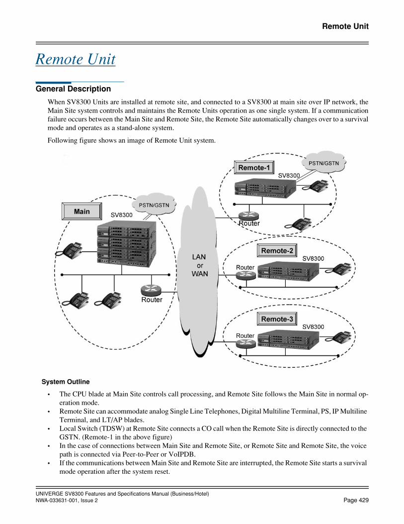
UNIVERGE SV8300 Features and Specifications Manual (Business/Hotel)NWA-033631-001, Issue 2 Page 429
Remote Unit
Remote Unit
General Description
When SV8300 Units are installed at remote site, and connected to a SV8300 at main site over IP network, theMain Site system controls and maintains the Remote Units operation as one single system. If a communicationfailure occurs between the Main Site and Remote Site, the Remote Site automatically changes over to a survivalmode and operates as a stand-alone system.
Following figure shows an image of Remote Unit system.
System Outline
• The CPU blade at Main Site controls call processing, and Remote Site follows the Main Site in normal op-eration mode.
• Remote Site can accommodate analog Single Line Telephones, Digital Multiline Terminal, PS, IP Multiline Terminal, and LT/AP blades.
• Local Switch (TDSW) at Remote Site connects a CO call when the Remote Site is directly connected to the GSTN. (Remote-1 in the above figure)
• In the case of connections between Main Site and Remote Site, or Remote Site and Remote Site, the voice path is connected via Peer-to-Peer or VoIPDB.
• If the communications between Main Site and Remote Site are interrupted, the Remote Site starts a survival mode operation after the system reset.
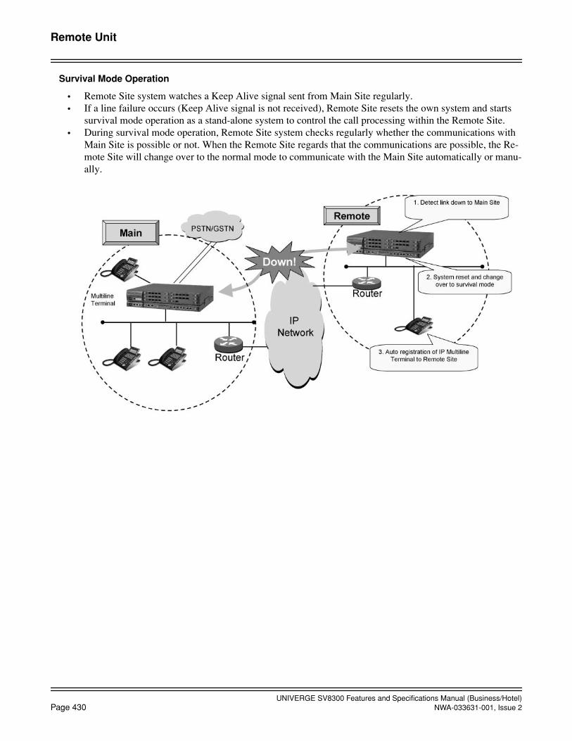
UNIVERGE SV8300 Features and Specifications Manual (Business/Hotel)Page 430 NWA-033631-001, Issue 2
Remote Unit
Survival Mode Operation
• Remote Site system watches a Keep Alive signal sent from Main Site regularly.• If a line failure occurs (Keep Alive signal is not received), Remote Site resets the own system and starts
survival mode operation as a stand-alone system to control the call processing within the Remote Site.• During survival mode operation, Remote Site system checks regularly whether the communications with
Main Site is possible or not. When the Remote Site regards that the communications are possible, the Re-mote Site will change over to the normal mode to communicate with the Main Site automatically or manu-ally.

UNIVERGE SV8300 Features and Specifications Manual (Business/Hotel)NWA-033631-001, Issue 2 Page 431
Remote Unit
Link Down Notice
This feature displays the link state between Main Site and Remote Site on the designated Digital Multiline Ter-minal or IP Multiline Terminal at both sites, and allows users at both sites to notice the link failure.
Log in destination of IP station (IP Multiline Terminal/Softphone)
SV8300 enables to log in any Units because accommodating destination of IP station is not limited by systemdata. Besides, same information can be seen from any Units with log in because all information of Dial by Nameand Call History is accumulated in Main Unit (UNIT#01).

UNIVERGE SV8300 Features and Specifications Manual (Business/Hotel)Page 432 NWA-033631-001, Issue 2
October, 2008
Remote Unit
Backup Call Routing to ISDN in Remote Unit Survival Mode
Calls within a Remote Unit network are made by dialing a station number. If IP network fails, the Remote Sitesystem works as a survival mode. In this case, calls to Main/Remote Sites can be automatically routed via ISDNnetwork. When the calling station dials the called station number, the system translates that number to the out-side telephone number and makes the outgoing call via ISDN.
Backup Call Routing to ISDN in Remote PIM Survival Mode
Station Application
All stations except following.Attendant Console, Desk Console, Add-On Module and ISDN Terminal are not available at Remote Site.
Operating Procedure
The same operating procedure as the Main Site applies for each service feature at Remote Site.
To display link down notice on a Multiline Terminal
1. When a link down occurs, the Link Down Notice button of Multiline Terminal that has been designated insystem programming flashes rapidly in red (240IPM).
2. Press the flashing button. “Link Down to Site xx” (xx: Site No.) is displayed on the LCD and the buttonflashes slowly in red (60IPM).
3. After six seconds, the LCD display returns to Clock/Calendar display. If you press the button again, themessage is displayed every time.
UNIVERGE SV8300 Features and Specifications Manual (Business/Hotel)NWA-033631-001, Issue 2 Page 433
October, 2008
Remote Unit
To confirm link ready notice and operation mode on a Multiline Terminal
1. When a link recovers, the lamp of Link Down Notice button flashes intermittently in green.
2. Press the flashing button. “Link Ready to Restore xx” (xx: Site No.) is displayed on the LCD during survivalmode operation.
3. After six seconds, the LCD display returns to Clock/Calendar display. If you press the button again, themessage is displayed every time.
4. When the Remote Site returns to normal operation mode that is subordinate to the Main Site, the lamp goesout.
5. Press the Link Down Notice button. “Normal Condition: R-PIM” is displayed on the LCD.
To move together with a terminal to a visitor site
1. Log out on your terminal, using the logout feature access code or the Logout feature key.
2. Move to another site (visitor site).
3. Specify the DRS of the terminal (Note) and reset its IP address, subnet mask and gateway address manuallyor using the DHCP server.
4. Log in by entering your station number and password to the visitor site.
5. Start using your terminal.
To move only with a station number to a visitor site
1. Log out on your terminal, using the logout feature access code or the Logout feature key.
2. Move to another site (visitor site).
3. Log in on a terminal where no one has logged in at the visitor site by entering your station number and pass-word.
4. Start using the new terminal.
To move together with a terminal to a visitor site without logout operation
1. Turn off the power of the terminal or disconnect its cable. The terminal will be logged out 1 or 2 minuteslater.
2. Move to another site (visitor site).
3. Specify the DRS of the terminal (Note) and reset its IP address, subnet mask and gateway address manuallyor using the DHCP server.
4. Log in by entering your station number and password to the visitor site.
5. Start using your terminal.
To move only with a station number without logout operation and override your station data
1. Move to another site (visitor site) without logout operation on your terminal.
2. Log in on a terminal where no one has logged in at the visitor site by entering your station number and pass-word.
3. “Override?” is displayed on the LCD of the new terminal.
4. Press the Yes key.
5. The terminal that you have left on the original site will be logged out.
6. Start using the new terminal.
UNIVERGE SV8300 Features and Specifications Manual (Business/Hotel)Page 434 NWA-033631-001, Issue 2
Remote Unit
To return from the visitor site to the home site together with a terminal
1. Log out on your terminal, using the logout feature access code or the Logout feature key.
2. Return to the original site (home site).
3. Specify the DRS of the terminal (Note) and reset its IP address, subnet mask and gateway address manuallyor using the DHCP server.
4. Log in by entering your station number and password to the home site.
5. Start using your terminal.
To return from the visitor site to the home site only with a station number
1. Log out on the terminal in the visitor site, using the logout feature access code or the Logout feature key.
2. Return to the original site (home site).
3. Log in on your original terminal accommodated in the original site (home site) by entering your stationnumber and password.
4. Start using the original terminal.
To return from the visitor site to the home site together with a terminal without logout operation
1. Turn off the power of the terminal or disconnect its cable. The terminal will be logged out 1 or 2 minuteslater.
2. Return to the original site (home site).
3. Specify the DRS of the terminal (Note) and reset its IP address, subnet mask and gateway address manuallyor using the DHCP server.
4. Log in by entering your station number and password to the home site.
5. Start using your terminal.
To return from the visitor site to the home site only with a station number without logout operation
1. Return to the original site (home site) without logout operation on the terminal in the visitor site.
2. Log in on your terminal accommodated in the original site (home site) by entering your station number andpassword.
3. “Override?” is displayed on the LCD of your terminal.
4. Press the Yes key.
5. The terminal that you have left on the visitor site will be logged out.
6. Start using your original terminal.
Note: Be sure to reset the terminal DRS setting (change the primary address to the DRS address for the site to whichyou have moved).
Service Conditions
General Conditions
1. Main Site should be SV8300.
2. Remote Site should be SV8300.
3. Key FD required for the whole system must be loaded to the Main Site.
UNIVERGE SV8300 Features and Specifications Manual (Business/Hotel)NWA-033631-001, Issue 2 Page 435
Remote Unit
4. The number of accommodated terminals/trunks in Main Site and Remote Site should be a maximum of1500 ports in the whole system.
5. The TCP/IP network is required between Main Site and Remote Site. The closed and bandwidth guaran-teed network is preferable, such as IP-VPN (Layer 3 VPN) or wide area Ethernet service (Layer 2 VPN).Following table shows the network requirement between Main Site and Remote Site.
If the network is short of the requirement, it may cause the delay operation of system, the delay and de-terioration of voice packets, disconnection of calls, and frequent changeover to survival mode at RemoteSite.
6. The CPU blade at Remote Site has the same system data as that at Main Site, because Remote Site auto-matically gets the data from Main Site at the time of setup. In normal operation, Main Site automaticallycopies the system data to Remote Site through the network once a day.
7. This feature is not compatible with Fusion service of 2400 IPX.
8. Spanning Tree (IEEE 802.1d) function is not available. Be sure to disable Spanning Tree function in theswitching hub that is connected with the CPU blade, VoIPDB and IP Multiline Terminal.
9. LACP (Link Aggregation Control Protocol, IEEE 802.3ad) function is not available. Be sure to disableLACP function in the switching hub that is connected with the CPU blade, VoIPDB and IP Multiline Ter-minal.
Conditions on System Configuration
1. The number of Remote Sites is a maximum of 46.
2. Remote Site can accommodate the following blades.BRT, PRT (ISDN), CCT(CCIS), DT1VoIPDB, DLC (Note), LC, COT, ODT, CSI
Note: Attendant Console, Desk Console, Add-On Module are not mountable at Remote Site.
3. The number of trunks accommodated at one Remote Site should be a maximum of 512.
4. Following is connected to the LAN port of the CPU blade at Main Site.Peer-to-Peer CCIS, OAI server, PCPro, SMDR, PMS
Conditions on Survival Mode at Remote Site
1. Remote Site starts survival mode operation in the following cases.
a. When the communications (Keep Alive signal) in every 30 seconds between Main Site and Remote Site are interrupted for a certain time (60 seconds in default, variable) on normal mode operation.
b. When Remote Site cannot be connected to Main Site or is not allowed to connect to Main Site afterthe system reset of the Remote Site.
Item Requirement
Protocol TCP/IP transparent
Maximum DelayTime
One-way Maximum 100 ms, return-way Maximum 200 ms (Recommended)One-way Maximum 120 ms, return-way Maximum 240 ms
Required Bandwidth (Control)
50 kbps
Required Bandwidth (Voice)
Depending on the traffic
UNIVERGE SV8300 Features and Specifications Manual (Business/Hotel)Page 436 NWA-033631-001, Issue 2
Remote Unit
2. Remote Site is reset automatically to change the operation from normal mode to survival mode when itdetects an interruption of the communications from/to Main Site.
3. When Remote Site starts the survival mode operation, the fault information “Reset from SV8300 PC Pro”is registered to the Remote Site. In addition, “Communication failure between Main Site and Remote Siteoccurred” (fault information 42) is registered in Main Site.
4. Remote Site on survival mode checks at every 30 seconds if the communications to Main Site are possi-ble. When the Remote Site regards that the communications are possible, “Communication failure be-tween Main Site and Remote Site recovered” (fault information 52) is registered to Main Site only.
5. When Remote Site on survival mode regards that the communications to Main Site are possible, manualchangeover (system reset) is required. Automatic changeover (reconnection to Main Site) is also select-able in system programming. At the automatic changeover, Remote Site system is initialized and the callson going are disconnected due to the reset of terminals.
Conditions on Service Features
1. The system clock at Remote Site synchronizes with the system clock at Main Site. If the communicationsto Main Site are interrupted, Remote Site does not synchronize and operates at the hardware clock on theCPU blade at Remote Site.
2. Remote Site cannot accommodate the built-in SIP trunk on the CPU blade.
3. A different metering area at each Remote Site is not available because Main Site corrects all call meteringthrough the whole system. If a call is originated from the COT at Remote Site, it is charged as the calloriginated from the COT at Main Site.
4. BGM service and Internal Zone Paging should not be used at Remote Site considering the traffic on thenetwork.
5. Digital Multiple line operation of Multiline Terminals can be used among different sites. In this case, thenetwork should have 10 Mbps or more bandwidth.
6. Automated Attendant should not be used at Remote Site considering the traffic.
7. Unavailable services at Remote Site are as follows.
• Add-On Module and ISDN Terminal are not mountable.
• VRS service is not available.
8. Different numbering plan for every site must not be assigned.
9. Since Main Site controls OAI, OAI clients cannot be used at Remote Site during survival mode operation.
10. Each Remote Site must provide a hold tone to the stations at the Remote Site.
• External hold tone (using Jack on the CPU blade): Tone source is required for each site.
• Internal hold tone: Available
• Hold tone using VRS: Not available
Conditions on Maintenance
1. You can connect PCPro to Remote Site via LAN. A built-in modem is not available in SV8300 PCProconnection to Remote Site.
2. Do not set and change the system data at Remote Site, except setting the Remote Site number. If the sys-tem data is set and changed at Remote Site, normal operation is not guaranteed. In addition, the systemdata copy from Main Site overwrites the system data in Remote Site once a day.
3. SNMP is not available at Remote Site.
4. Remote System Upgrade is available via LAN (FTP) at each site.

UNIVERGE SV8300 Features and Specifications Manual (Business/Hotel)NWA-033631-001, Issue 2 Page 437
Remote Unit
5. Resident system programming must not be used.
6. AP program upgrade is not available for the AP blades at Remote Site.
7. The MJ/MN alarm indications are not available at Remote Site. If a fault occurs at Remote Site, the faultis notified to the Main Site and the MJ/MN alarm is indicated at the Main Site.
8. On-line expansion for LC/DLC/COT blades is supported and it enables the tone/path connection even ifthe system data copy is not activated to the Remote Site. After completing all expansions for LC/DLC/COT blades, be sure to execute the system data copy to the Remote Site. Note that the expanded data willnot be added if the Remote Site starts survival mode operation before the system data copy.
9. After changing the IP address and TCP port numberVoIPDB, the changed data is reflected when the MakeBusy key of the corresponding VoIPDB card is set to ON then OFF, even if the system data copy is notexecuted. This is only available for change of IP address and TCP port number of IP-VoIPDB.
Conditions on Link Down Notice
1. Link Down Notice is available only for Digital Multiline Terminal and IP Multiline Terminal (SIP) ac-commodated in SV8300. This is not available for a single line telephone.
2. For message display, Digital Multiline Terminal/IP Multiline Terminal (SIP) with 24-digit or more LCDis recommended. 16-digit LCD may not display all messages properly.
3. Notification message can be displayed regardless of idle or busy state of Digital Multiline Terminal, writ-ing the message over the present display. After six seconds, the display returns to the Clock/Calendar dis-play automatically.
4. The system detects a Link Down on condition that UDP connection between Main Site and Remote Siteis interrupted for 20-50 seconds (variable in system programming).
5. The system detects the Link Ready on condition that UDP connection between Main Site and Remote Siterecovers for 110-150 seconds (variable in system programming). After the link is ready, the lamp of but-ton keeps flashing during the Remote Site operates on survival mode. Since the color of lamp and the in-dication interval changes, an administrator at the Remote Office can changeover the system operationfrom survival mode to normal remote mode according to this indication.
6. When the link between Main Site and Remote Site recovers and the Remote Site starts subordinate oper-ation to the Main Site, the flashing lamp of the button goes out.

UNIVERGE SV8300 Features and Specifications Manual (Business/Hotel)Page 438 NWA-033631-001, Issue 2
Remote Unit
Conditions on Backup Call Routing to ISDN in Remote Unit Survival Mode
General Conditions
1. ISDN trunk must be accommodated in the site where this feature is used. Both the basic rate interface (BRI)and the primary rate interface (PRI) can be used. And there is no restriction of BRT/PRT firmware.
2. The calling side terminals are Single Line Telephone, Digital Multiline Terminal, IP Multiline Terminal(SIP), Soft phone, PS, and DID trunk (trunk with caller ID information). The table below shows the opera-tional availability of the ISDN routing by terminal combination of calling and called side. See Conditionsof ISDN Routing Operation for details.
X: Available, -: Not available, ∆: Partly available (with some conditions)
3. When this feature is used, tenant must be assigned in each site.
4. While an ISDN routing connection is established, if the site in survival mode returns to normal mode, thecall is disconnected.
Called side
Calling side
Digital Multiline Terminal,
IP Multiline Terminal (SIP), Soft Phone,
SLT
PSAttendant console
ISDN terminalVirtual station
Digital Multiline Terminal,
IP Multiline Terminal (SIP), Soft Phone,
SLT
X ∆ -
PS X ∆ -
Virtual station(Sub-line origination) X ∆ -
DID Trunk X ∆ -
Ring down trunk X ∆ -
Attendant Console - - -
ISDN Terminal - - -
UNIVERGE SV8300 Features and Specifications Manual (Business/Hotel)NWA-033631-001, Issue 2 Page 439
Remote Unit
Conditions of ISDN Routing Operation
1. The ISDN routing is operable not only from the remote site to the main site, but also from main to remote,and from remote to remote.
2. The ISDN routing is performed only 1) when a call is originated from a station to a station within a RemoteUnit system, 2) when a station places a call on hold and originates a call to another station (in ConsultationHold), and 3) when a call terminates from DID trunk to a station. (Voice Mail station is included)
3. When the terminating destination is a PS or there may be a case where the intended ISDN routing is notavailable, because the terminal’s location cannot be specified. The terminal is considered to be located inthe site registered for each PS virtual station number in system data, and whether to enable the ISDN routingto the site is decided. The routing call cannot terminate to the PS, if it is moving to the site in survival modewhere the PS does not originally belong. And also, if the PS is moving from the site where it normally be-longs, the PS cannot originate a call by the ISDN routing.
4. When the terminating destination is a virtual station, a station in another office or with trunk originationacross the sites, the ISDN routing is disabled. With a trunk termination across the sites, the ISDN routingis operable, such as the case that a call terminates from a trunk in a site to a station in another site.
5. The ISDN routing starts either when the site of the calling station is in survival mode, or when the site ofthe called station is in survival mode. Therefore, even if the transmission between the main and the remoteis unavailable, the ISDN routing is not performed until a mode switches to survival mode.
6. Whether to enable the ISDN routing can be specified by system data programming for each tenant of thecalling station and the station’s service restriction class. When the calling side is a trunk, it is specified bythe trunk route setting.
7. Only the ISDN trunk origination is supported to enable the backup call routing. Route origination, routeadvance origination and LCR are available.
8. For the ISDN routing, a trunk access code must be assigned for each calling tenant in system data program-ming.
9. The designation method of terminating destination of ISDN routing can be selected from the following ac-cording to setting data for each terminating station tenant.
• Designation of terminating destination per station basis
• Designation of terminating destination per terminating tenant basis
• Designation of subaddress per terminating tenant basis
10. If the entire ISDN origination trunks are busy at ISDN routing, the calling party receives reorder tone.
11. The terminating trunk should be an ISDN trunk.
12. On an origination to the ISDN routing, the peg count for the number of origination to the ISDN routing iscounted. Acquiring the peg count in the main site is possible. It is counted in the Remote Unit also, but thedata may not be relevant because it becomes indefinite when the remote site returns to normal mode.
13. For trunk selection on an origination to the ISDN routing, it is performed in the tenant of the calling stationin the case of station-to-station calling, and it is performed in the tenant of terminating trunk in the case oftrunk to station calling.
14. The area code restriction and the billing on an origination to ISDN routing are performed in the terminatingstation. However, billing for the remote site in survival mode is not possible.
15. As a caller ID on origination to ISDN routing, the caller ID of the calling station is notified in the case ofstation-to-station calling, and the caller ID of the terminating station is notified in the case of trunk to stationcalling.
16. The ISDN routing is also operable when calls are originated with following calling operations:

UNIVERGE SV8300 Features and Specifications Manual (Business/Hotel)Page 440 NWA-033631-001, Issue 2
Remote Unit
• Last Number Redial
• Outgoing Call History (Stack Dial)
• Speed Dialing - One touch key
• Station Speed Dialing / System Speed Dialing
• Voice Mail Retrieve
• Hotline / Delayed Hotline
Conditions of Routing Methods
Designation of Terminating Destination per Station Basis
1. When the system data for the terminating destination number per station basis is not copied to the site ofthe calling station, this feature is not operated.
2. When the terminating destination is a virtual station, this method is not available.
Designation of Terminating Destination per Terminating Tenant Basis
1. When the system data for the terminating destination number per terminating tenant basis is not copied tothe site of the calling station, this feature is not operated.
Designation of Subaddress per Terminating Tenant Basis
1. It depends on the ISDN network specification whether the terminating subaddress is usable.
2. When the system data for the terminating destination number per terminating tenant basis is not copied tothe site of the calling station, this feature is not operated.
Other Conditions
1. The priority of this feature and other service features are as follows. Service features that operate on a station calling
The features with lower priority than ISDN routing are performed in the site after trunk termination byISDN routing.
2. Since billing operation in the main site (SMDR is also located in the main site) is a condition of the RemoteUnit feature, if the calling party is a station in the main site, the billing is performed in the same way as anormal trunk origination. Meanwhile, if the calling party is a station in the remote site, billing is not possi-ble.
Service Features Priority
Restriction of connection between tenants HighMA ForwardingISDN Routing with survival mode of Remote Unit: Designate a desti-nation per station/tenantMultiline Terminal Attendant Position: Night TransferCall Forwarding - LogoutCall Forwarding - All Calls/Split Call Forwarding - All CallsUCDDo Not DisturbStation HuntingCall Forwarding - Busy Line/Split Call Forwarding - Busy LineCall Forwarding - No Answer/Split Call Forwarding - No Answer Low

UNIVERGE SV8300 Features and Specifications Manual (Business/Hotel)NWA-033631-001, Issue 2 Page 441
Remote Unit
List of Service Features Operation
X: Available-: Not available
Note 1: Fault message during survival mode disappears when Remote Site returns to the normal mode.
Service Features Main UnitRemote Unit
Normal Mode Survival Mode
Multiline Terminal, SLT operation X X X
IP Multiline Terminal (SIP) operation X X X
COT, LDT, ODT X X X
Attendant Console X - -
Add-On Module X - -
DSS Console X X X
ISDN Terminal X - -
OAI client X X -
PS, ZT X X X
Trunk IC/OG call (CO, Tie line) X X X
Caller ID Class X X X
Caller ID Display (MFC, T1-ANI) X - -
Caller ID Display (ISDN) X X X
Caller ID-Station X X X
CCIS X X X
SMDR X - -
PCPro (LAN) X X X
PCPro (Modem) X - X
System Data change by SV8300 PCPro X - X
SNMP X - -
VLAN X X X
Fault Message registration X - X (Note 1)
Announcement Service X - -
Automated Attendant X - -
Conference (Three/Four Party) X X X
Internal Zone Paging X - -

UNIVERGE SV8300 Features and Specifications Manual (Business/Hotel)Page 442 NWA-033631-001, Issue 2
October, 2008
Remote Unit
System Port Capacity of Remote UNIT Network
SV8300 Maximum System Port Capacity
Item1 Unit 2 Units 3 Units 4 Units System Max.
2Ux1 2Ux2 2Ux3 2Ux6 2Ux9 2Ux12 Standalone Remote Unit
Blade Slots 6 12 18 36 54 72 72 900
PortsPhysical Port 108 216 324 648 972 1296 1296
20481536
2048Virtual Port 1536 1536 1536
Physical Port
SLT (-24V) 96 192 288 576 864 1152 1152
1536
1536
1536
SLT (-48V) 24 48 72 144 216 288 288 1536Digital Multiline Terminal (-48V)
Dterm Series i/DT300)
96 192 288 576 864 1152 1152 1536
Digital Multiline Terminal (-48V)
Dterm/with APR [Dual Port Mode]) (Note 1)
54(54)
108(108)
162(162)
324(324)
486(486)
648(648)
648(648)
768(768)
DSS console
(for Dterm Series i/DT300 Series) (Note 2)
32 32 32
Desk Console (Note 3)
8 8 8
ISDN Terminal (BRI)
48 96 114 256 256 256
ZT/CS interface (CSI)
48 96 114 288 384 384 384
In-Skin UMS 48 96 128 128 128
Virtual Port
IP Multiline Terminal (Dterm IP Series i)
1024 1024 1024
SIP Multiline Ter-minal (DT700 Series)
1024 1024 1024
Softphone 1024 1024 1024WiFi Handset (MH240)
1024 1024 1024
PS 512 512 512DSS console (for DT700 Series) (Note 2)
32 32 32

UNIVERGE SV8300 Features and Specifications Manual (Business/Hotel)NWA-033631-001, Issue 2 Page 443
October, 2008
Remote Unit
2U=Expansion Chassis
Note 1: When using Dterm with APR (Dual Port Mode), the physical ports for analog station shown in parenthesisare required in addition to the physical ports for Multiline Terminal.
Note 2: The total number of following DSS Console is maximum 32 per system.DSS Console (for Dterm Series i/DT300 Series)DSS Console (for DT700 Series)
Note 3: Available at main unit (UNIT#1) only.Note 4: The total number of following functions is maximum 52 per Unit.
- Caller ID Receiver- MF Receiver- DTMF Receiver- Caller ID Sender
Note 5: The following conference groups can be configured.- One, 32-Party conference group- Two, 16-Party conference groups- Four, eight-Party conference groups
Note 6: It is not available in R1/R2 version.
Physical Port
Central Office Trunk
COT 48 96 144 288 432 512 512
512
512
512
DID 24 48 72 144 216 288 288 512
Tie Line Trunk
E&M 24 48 72 144 216 288 288 512
BRI Trunk 48 96 144 256 256 256PRI (23B+D) Trunk
96 192 288 504 504 504
PRI (30B+D) Trunk
93 186 279 512 512 512
DTI (T1) Trunk 96 192 288 504 504 504CCIS (1.5M) Trunk
96 192 288 384 384 384
CCIS (2M) Trunk 93 186 279 496 496 496
Virtual Port
IP Trunk(P2P CCIS)
512 512 512
SIP Trunk (Note 3)
96 96 96
VoIP Channel
W/RTP 128 256 384 512 512 512+W/sRTP (Note 6) 96 192 288 384 384 384+
Modem Channel (Note 3) 1 1 1VRS Message (Note 3) 8 8 8MF Sender (Note 3) 64 64
6464
64Caller ID Receiver (Note 4) 52 64 64 64MF Receiver (Note 4) 52 64 64 64DTMF Receiver (Note 4) 32 32 32Caller ID Sender (Note 4) 16 16 163/4-Party Conference Resources
64 128 128128
128128
32-Party Conference Resources (Note 5)
32 32 32
SV8300 Maximum System Port Capacity (Continued)
Item1 Unit 2 Units 3 Units 4 Units System Max.
2Ux1 2Ux2 2Ux3 2Ux6 2Ux9 2Ux12 Standalone Remote Unit
UNIVERGE SV8300 Features and Specifications Manual (Business/Hotel)Page 444 NWA-033631-001, Issue 2
Reserve Power
Reserve Power
General Description
This feature provides backup power from a 24-volt battery source in the event of a commercial power failure.
Station Application
Not applicable.
Operating Procedure
No manual operation is required.
Service Conditions
1. Batteries should be installed inside the Chassis or separately from the system.
2. Sealed lead acid (or maintenance-free) batteries must be locally provided.
3. No interruption of system operation should occur while switching from commercial to battery power. How-ever, when the system senses the supplied voltage from the batteries has dropped to 20-21 volts, the systemwill automatically shut down to prevent excessive discharge of the Reserve Power batteries.
4. Duration of battery operation is a direct function of the capacity of the batteries installed, and the quantityand types of cards installed.
5. The Reserve Power requirements are dependent on the configuration of each individual system.
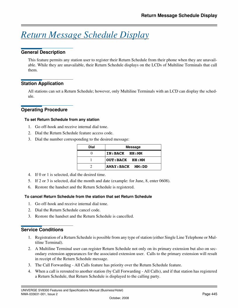
UNIVERGE SV8300 Features and Specifications Manual (Business/Hotel)NWA-033631-001, Issue 2 Page 445
October, 2008
Return Message Schedule Display
Return Message Schedule Display
General Description
This feature permits any station user to register their Return Schedule from their phone when they are unavail-able. While they are unavailable, their Return Schedule displays on the LCDs of Multiline Terminals that callthem.
Station Application
All stations can set a Return Schedule; however, only Multiline Terminals with an LCD can display the sched-ule.
Operating Procedure
To set Return Schedule from any station
1. Go off-hook and receive internal dial tone.
2. Dial the Return Schedule feature access code.
3. Dial the number corresponding to the desired message:
4. If 0 or 1 is selected, dial the desired time.
5. If 2 or 3 is selected, dial the month and date (example: for June, 8, enter 0608).
6. Restore the handset and the Return Schedule is registered.
To cancel Return Schedule from the station that set Return Schedule
1. Go off-hook and receive internal dial tone.
2. Dial the Return Schedule cancel code.
3. Restore the handset and the Return Schedule is cancelled.
Service Conditions
1. Registration of a Return Schedule is possible from any type of station (either Single Line Telephone or Mul-tiline Terminal).
2. A Multiline Terminal user can register Return Schedule not only on its primary extension but also on sec-ondary extension appearances for the associated extension user. Calls to the primary extension will resultin receipt of the Return Schedule message.
3. The Call Forwarding - All Calls feature has priority over the Return Schedule feature.
4. When a call is rerouted to another station (by Call Forwarding - All Calls), and if that station has registereda Return Schedule, that Return Schedule is displayed to the calling party.
Dial Message
0 IN:BACK HH:MM
1 OUT:BACK HH:MM
2 AWAY:BACK MM:DD
UNIVERGE SV8300 Features and Specifications Manual (Business/Hotel)Page 446 NWA-033631-001, Issue 2
October, 2008
Return Message Schedule Display
5. The feature access code for Return Schedule can be programmed in a DSS key on the Multiline Terminal.
6. Up to three different messages can be selected:
a. IN:BACK: recommended when the station user is not at his/her desk but is still on premises (in a meeting, in the building, etc.) Provides an hour and minute display.
b. OUT:BACK: recommended when the station user has left the premises but will be back within thesame day. Provides an hour and minute display.
c. AWAY: BACK: recommended when the station user has left the premises and will be away for anextended time period. Provides a month and date display.
7. Reorder tone is heard by the calling party when a station that set Return Schedule is called.
8. The lower portion of the LCD on a Multiline Terminal is used to provide the Return Schedule display.
9. Entry of return time is through 4 dialed digits (HH/MM) for hours and minutes.
10. Entry of return date is through 4 dialed digits (MM/DD) representing the month and day.

UNIVERGE SV8300 Features and Specifications Manual (Business/Hotel)NWA-033631-001, Issue 2 Page 447
Room Cutoff
Room Cutoff
General Description
This feature allows the following types of terminals to temporarily restrict guest room telephones from makingunauthorized calls when guests are away from their rooms. This feature allows the same restriction when therooms are in Check Out status:
• Attendant Console• Hotel/Motel (H/M) Front Desk Instrument• Property Management System (PMS) terminal• Guest room telephones using a special access code
There are two types of Room Cutoff conditions depending on the type of calls restricted.
• External Call Restriction: All outgoing calls from guest room stations are restricted in the Room Cutoff status. (Only internal calls are available.)
• Toll Call Restriction: All toll calls from guest room stations are restricted during Room Cutoff status. (Internal and local calls are available.)
Station Application
All stations except House Phones.
Operating Procedure
External Call Restriction
To set Room Cutoff from the Attendant Console
1. Dial the desired station number.
2. Press the RC key.
3. Press the ANS key.
4. Press the RLS key.
To cancel Room Cutoff from the Attendant Console
1. Dial the desired station number.
2. Press the RC key.
3. Press the RESET key.
4. Press the RLS key.
To set Room Cutoff from the Hotel/Motel Front Desk Instrument
1. Press the RC key.
2. Dial the desired station number.
3. Press the SET key. The above two steps can be repeated for other stations.
4. Press the RLS key.
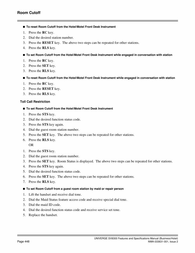
UNIVERGE SV8300 Features and Specifications Manual (Business/Hotel)Page 448 NWA-033631-001, Issue 2
Room Cutoff
To reset Room Cutoff from the Hotel/Motel Front Desk Instrument
1. Press the RC key.
2. Dial the desired station number.
3. Press the RESET key. The above two steps can be repeated for other stations.
4. Press the RLS key.
To set Room Cutoff from the Hotel/Motel Front Desk Instrument while engaged in conversation with station
1. Press the RC key.
2. Press the SET key.
3. Press the RLS key.
To reset Room Cutoff from the Hotel/Motel Front Desk Instrument while engaged in conversation with station
1. Press the RC key.
2. Press the RESET key.
3. Press the RLS key.
Toll Call Restriction
To set Room Cutoff from the Hotel/Motel Front Desk Instrument
1. Press the STS key.
2. Dial the desired function status code.
3. Press the STS key again.
4. Dial the guest room station number.
5. Press the SET key. The above two steps can be repeated for other stations.
6. Press the RLS key.
OR
1. Press the STS key.
2. Dial the guest room station number.
3. Press the SET key. Room Status is displayed. The above two steps can be repeated for other stations.
4. Press the STS key again.
5. Dial the desired function status code.
6. Press the SET key. The above two steps can be repeated for other stations.
7. Press the RLS key.
To set Room Cutoff from a guest room station by maid or repair person
1. Lift the handset and receive dial tone.
2. Dial the Maid Status feature access code and receive special dial tone.
3. Dial the maid ID code.
4. Dial the desired function status code and receive service set tone.
5. Replace the handset.

UNIVERGE SV8300 Features and Specifications Manual (Business/Hotel)NWA-033631-001, Issue 2 Page 449
Room Cutoff
Service Conditions
1. Stations in Room Cutoff condition are able to place outgoing calls using the Attendant Assisted Calling fea-ture.
2. If the station under Room Cutoff status dials a Analog CO Line access code and/or a special area code, thestation is rerouted to one of the following:
• Reorder tone
• Attendant Console
3. Room Cutoff is automatically set by Check Out operation, and it is automatically reset by Check In opera-tion.
4. Room Cutoff is available for guest room stations only.
5. Station-to-Station calling and service feature access (such as Maid Status) are still available.
6. Setting and cancelling this feature from the PMS terminal requires Built-in PMS (IP).
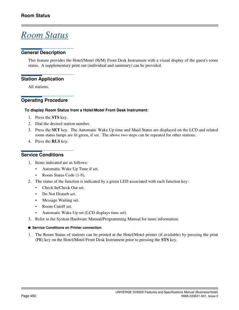
UNIVERGE SV8300 Features and Specifications Manual (Business/Hotel)Page 450 NWA-033631-001, Issue 2
Room Status
Room Status
General Description
This feature provides the Hotel/Motel (H/M) Front Desk Instrument with a visual display of the guest's roomstatus. A supplementary print out (individual and summary) can be provided.
Station Application
All stations.
Operating Procedure
To display Room Status from a Hotel/Motel Front Desk Instrument:
1. Press the STS key.
2. Dial the desired station number.
3. Press the SET key. The Automatic Wake Up time and Maid Status are displayed on the LCD and relatedroom status lamps are lit green, if set. The above two steps can be repeated for other stations.
4. Press the RLS key.
Service Conditions
1. Items indicated are as follows:
• Automatic Wake Up Time if set.
• Room Status Code (1-8).
2. The status of the function is indicated by a green LED associated with each function key:
• Check In/Check Out set.
• Do Not Disturb set.
• Message Waiting set.
• Room Cutoff set.
• Automatic Wake Up set (LCD displays time set).
3. Refer to the System Hardware Manual/Programming Manual for more information.
Service Conditions on Printer connection
1. The Room Status of stations can be printed at the Hotel/Motel printer (if available) by pressing the print(PR) key on the Hotel/Motel Front Desk Instrument prior to pressing the STS key.
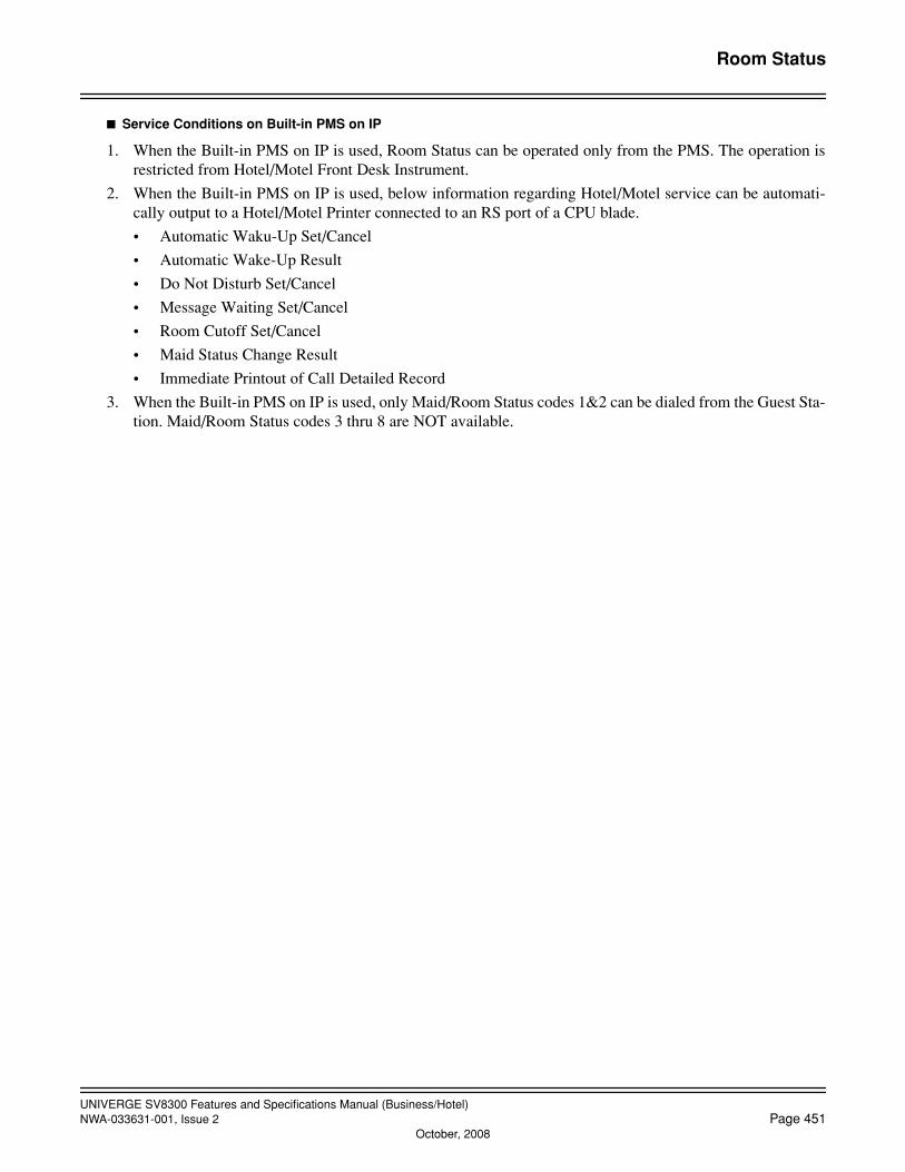
UNIVERGE SV8300 Features and Specifications Manual (Business/Hotel)NWA-033631-001, Issue 2 Page 451
October, 2008
Room Status
Service Conditions on Built-in PMS on IP
1. When the Built-in PMS on IP is used, Room Status can be operated only from the PMS. The operation isrestricted from Hotel/Motel Front Desk Instrument.
2. When the Built-in PMS on IP is used, below information regarding Hotel/Motel service can be automati-cally output to a Hotel/Motel Printer connected to an RS port of a CPU blade.
• Automatic Waku-Up Set/Cancel
• Automatic Wake-Up Result
• Do Not Disturb Set/Cancel
• Message Waiting Set/Cancel
• Room Cutoff Set/Cancel
• Maid Status Change Result
• Immediate Printout of Call Detailed Record
3. When the Built-in PMS on IP is used, only Maid/Room Status codes 1&2 can be dialed from the Guest Sta-tion. Maid/Room Status codes 3 thru 8 are NOT available.
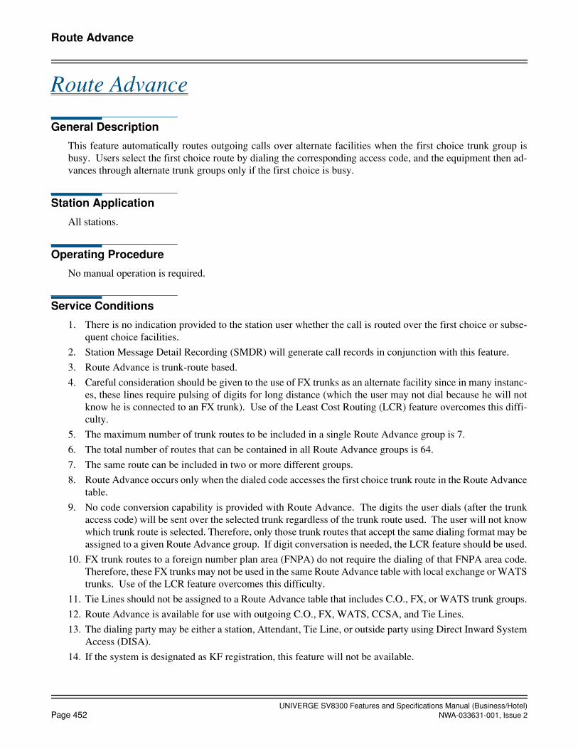
UNIVERGE SV8300 Features and Specifications Manual (Business/Hotel)Page 452 NWA-033631-001, Issue 2
Route Advance
Route Advance
General Description
This feature automatically routes outgoing calls over alternate facilities when the first choice trunk group isbusy. Users select the first choice route by dialing the corresponding access code, and the equipment then ad-vances through alternate trunk groups only if the first choice is busy.
Station Application
All stations.
Operating Procedure
No manual operation is required.
Service Conditions
1. There is no indication provided to the station user whether the call is routed over the first choice or subse-quent choice facilities.
2. Station Message Detail Recording (SMDR) will generate call records in conjunction with this feature.
3. Route Advance is trunk-route based.
4. Careful consideration should be given to the use of FX trunks as an alternate facility since in many instanc-es, these lines require pulsing of digits for long distance (which the user may not dial because he will notknow he is connected to an FX trunk). Use of the Least Cost Routing (LCR) feature overcomes this diffi-culty.
5. The maximum number of trunk routes to be included in a single Route Advance group is 7.
6. The total number of routes that can be contained in all Route Advance groups is 64.
7. The same route can be included in two or more different groups.
8. Route Advance occurs only when the dialed code accesses the first choice trunk route in the Route Advancetable.
9. No code conversion capability is provided with Route Advance. The digits the user dials (after the trunkaccess code) will be sent over the selected trunk regardless of the trunk route used. The user will not knowwhich trunk route is selected. Therefore, only those trunk routes that accept the same dialing format may beassigned to a given Route Advance group. If digit conversation is needed, the LCR feature should be used.
10. FX trunk routes to a foreign number plan area (FNPA) do not require the dialing of that FNPA area code.Therefore, these FX trunks may not be used in the same Route Advance table with local exchange or WATStrunks. Use of the LCR feature overcomes this difficulty.
11. Tie Lines should not be assigned to a Route Advance table that includes C.O., FX, or WATS trunk groups.
12. Route Advance is available for use with outgoing C.O., FX, WATS, CCSA, and Tie Lines.
13. The dialing party may be either a station, Attendant, Tie Line, or outside party using Direct Inward SystemAccess (DISA).
14. If the system is designated as KF registration, this feature will not be available.

UNIVERGE SV8300 Features and Specifications Manual (Business/Hotel)NWA-033631-001, Issue 2 Page 453
Save and Repeat
Save and Repeat
General Description
This feature allows a Digital Multiline Terminal to save a specific dialed number and then redial that number ata later time.
Station Application
All Digital Multiline Terminals.
Operating Procedure
1. Go off-hook and seize any idle line. Dial a number.
2. After the number has been dialed, press the Save and Repeat key. The dialed number is stored for futureuse. The associated LED lights red.
3. To access this number later, go off-hook and receive dial tone. Press the Save and Repeat key and the savednumber is dialed.
Service Conditions
1. Three Save and Repeat keys per station can be assigned.
2. The Save and Repeat function may be set at any time after the number has been dialed and before going on-hook.
3. It is not necessary to erase the stored number to save another. The second number will automatically replacethe first.
4. If necessary, dialing can be added after pressing the Save and Repeat key.
5. When a call is originated using the Save and Repeat feature, the LED associated with the Save and Repeatkey goes out. However, the memory is retained and that number can be accessed again.
6. To monitor the saved digits, press the Save and Repeat key while the station is idle. The saved digits willbe displayed if the Digital Multiline Terminal is equipped with an LCD.
7. The trunk access code is saved along with the dialed number on a Trunk Direct Appearance. This allowsuse of the Save and Repeat key on an extension.
8. The maximum number of digits that can be stored is 26.

UNIVERGE SV8300 Features and Specifications Manual (Business/Hotel)Page 454 NWA-033631-001, Issue 2
Security Alarm
Security Alarm
General Description
This feature provides an indication on the Attendant Console when a contact closure occurs.
Station Application
Not applicable.
Operating Procedure
No manual operation is required.
Service Conditions
1. The contact to be monitored is connected across Tip (T) and Ring (R) of one circuit on a LC blade.
2. The contact installed must be a normally open contact.
3. The contact generated signal is non-latching; therefore, if the contact opens again, the signal to the Atten-dant Console stops.
4. The station number assigned to the single line circuit associated with the contact closure is displayed whenthe Attendant presses the ATND key or ANSWER key.
5. Assignment of this feature is accomplished using Hotline assignment of a single line extension to the At-tendant Console. Refer to the Hotline - Inside/Outside Features and Specifications for more information.
UNIVERGE SV8300 Features and Specifications Manual (Business/Hotel)NWA-033631-001, Issue 2 Page 455
October, 2008
Semi-Automatic Attendant Camp-On
Semi-Automatic Attendant Camp-On
General Description
This feature permits the Attendant to hold an incoming call in a special mode when the desired station for thetransfer is busy. The Attendant sends a Camp-On tone to the busy station.
When that station becomes idle, the Attendant is recalled automatically. After the Attendant answers the recall,the station is called automatically. When the station answers the Attendant call and the attendant releases, thestation is automatically connected to the waiting party.
Station Application
Attendant Consoles.
Operating Procedure
To activate a Camp-On from the Attendant Console
1. Dial the desired station and receive busy tone.
2. Press the RELEASE key.
3. Camp-On tone is sent to the station and Camp-On is set.
4. When the station becomes idle, the Attendant is recalled automatically.
5. Press the LOOP key recalled.
6. Camped-On station is called automatically and the Attendant hears ring back tone.Note 1: If the station has become a state other than the idle state after the procedure 5, the Attendant hears busy
tone.Note 2: If the station has been in the two-party connection state (station to another station/station to trunk) after
the procedure 5, the Attendant hears busy tone. By pressing the RELEASE key again in this state, Semi-Automatic Attendant Camp-On can be set again.
Note 3: In the case of Automatic Recall, the Attendant hears busy tone. By pressing the RELEASE key again in thisstate, Semi-Automatic Camp-On can be set again.
7. When the Camped-On station answers the call, the Attendant and the station are connected.
8. Press the RELEASE key. The station is connected to the held party.
OR
Press the TALK key. The Attendant can join in a three-party conference with the calling and called parties.
OR
Press the DEST key. The Attendant can speak with the held party.
To cancel a Camp-On from the Attendant Console
1. Press the LOOP key corresponding to held call.
2. Press the DEST key and receive busy tone.
3. Press the CANCL key and automatically return to the held party.
UNIVERGE SV8300 Features and Specifications Manual (Business/Hotel)Page 456 NWA-033631-001, Issue 2
October, 2008
Semi-Automatic Attendant Camp-On
To re-enter the call that has been Camped-On from the Attendant Console before being recalled
1. Press the LOOP key corresponding to held call.
2. The busy station number and name are displayed for six seconds in the left side of the console’s display (ifprovided by System Data).
3. Converse with the held party.
OR
1. Dial the Call Pickup-Direct feature access code and receive feature dial tone.
2. Dial the extension number of desired busy station.
3. Converse with the held party.
Service Conditions
1. The type of Attendant Camp-On is selectable from Attendant Camp-On or Semi-Automatic AttendantCamp-On on a system basis in system data programming.
2. Attendant Camp-On can be set when the busy station is connected to another station or trunk in a two-partyconnection.
3. Attendant Camp-On is denied if the busy station is
• dialing
• in Line Lockout
• receiving a system generated tone
• a Data Station protected against any override by DND key
• currently connected to a Camped-On call
or any of the following features is activated on the busy station:
• Attendant Override • Consultation Hold
• Call Transfer • Data Line Security
• Camp-On • Executive Override
• Conference • Hold
• Privacy • Paging
• Voice Call
When Camp-On is denied, the Attendant will receive reorder tone.
4. The maximum number of simultaneous Camp-Ons per Attendant is six, regardless of the setting of Atten-dant Loop Release function.
5. The station receiving the Camp-On can answer using the Call Hold feature or Answer Key feature. Repeat-ed use of these features allows the station to alternate between the calls (Broker’s Call).
6. Calls that remain Camped-On for longer than a predetermined time will initiate an Automatic Recall to theAttendant that set the Camp-On.
7. The Camped-On station is in idle state until a Camp-On call is placed from the Attendant after the stationbecomes idle. During this period, a call can be terminated on the station or the station can perform normaloperation in the ordinary idle state. If a Camped-On station is called from any other party, following con-ditions are applied.
a. Even when a Camped-On station is a Voice Mail station, MCI is not output.
b. When a Camped-On station is a Digital Multiline Terminal, calling party information = attendant

UNIVERGE SV8300 Features and Specifications Manual (Business/Hotel)NWA-033631-001, Issue 2 Page 457
October, 2008
Semi-Automatic Attendant Camp-On
console (“operator”) is displayed. The attendant console displays information about the called partyand ring back tone is connected.
c. OAI function is not available.
d. When Call Forwarding – All Calls or Do Not Disturb is set until a Camp-On call is placed after thestation becomes idle, the setting for those functions is valid from the next call of the Camp-On call.
8. For Attendant Camp-On with Tone Indication - CCIS, Attendant Camp-On is used, regardless of the settingof Attendant Camp-On type. Semi-Automatic Attendant Camp-On is not used.
9. If the pilot station for UCD/Station Hunting is called from an Attendant, the call can be camped-on to thepilot station when all stations in the group are busy. When the pilot station becomes idle, the Attendant isrecalled for Camp-On. The Attendant is not recalled even if a member station becomes idle.
UNIVERGE SV8300 Features and Specifications Manual (Business/Hotel)Page 458 NWA-033631-001, Issue 2
October, 2008
Set Relocation
Set Relocation
General Description
This feature enables two stations to be moved from one location to another without programming station dataat the PCPro.
Station Application
From Multiline Terminal to Multiline Terminal.
From Single Line Terminal to Single Line Terminal.
Operating Procedure
To move Station A to Station B:
1. Lift handset at Station A. Receive Dial Tone.
2. Dial Authorization Code access code. Receive Special Dial Tone.
3. Dial Authorization Code for changing station class temporarily. Receive Dial Tone.
4. Dial Set Relocation access code. Receive Special Dial Tone.
5. Dial Station B number; receive Service Set Tone and LCD displays SWAP OK xxxx (where xxxx isStation B number).
6. Restore the handset; After four seconds, data between Station A and Station B will be exchanged.
Service Conditions
1. This feature can move Multiline Terminal to Multiline Terminal, or Single Line Terminal to Single LineTerminal.
The following cases are not available:
• Single Line Terminal ↔ Digital Multiline Terminal/IP Multiline Terminal
• PS ↔ PS/Single Line Terminal/Digital Multiline Terminal/IP Multiline Terminal
• ↔ Digital Multiline Terminal/IP Multiline Terminal
However, the following cases are available (Note);
• Single Line Terminal (DP) ↔ Single Line Terminal (PB)
• Between Multiline Terminals with different line button number Note: In this case, telephone sets also should be changed.
2. When the station has the following features, it cannot be moved:
• Single Line Terminal equipped with DSSCON
• Multiline Terminal equipped with Add-On-Module
• Multiline Terminal equipped with APR
• Multiline Terminal equipped with Dual Path
In this case, when dial Set Relocation access code, receive restrict reorder tone.

UNIVERGE SV8300 Features and Specifications Manual (Business/Hotel)NWA-033631-001, Issue 2 Page 459
October, 2008
Set Relocation
3. The following services cannot be moved:
• Last Number Redial
• Save and Repeat
4. When the station is busy, it cannot be moved.
5. This feature is selectable by service restriction class.
6. When Multiline Terminal is moved to Multiline Terminal:
• The LED status of Multiline (Trunk, station) cannot be moved.
• If Call Forwarding-All Calls/-Busy Line/-No Answer, Do Not Disturb, Message Waiting (MW), orBusy-Out is setting, the associated LED will be lit.
7. When Single Line Terminal is moved to Single Line Terminal while MW is setting, then MW lamp will belit after moving.
8. During saving/loading system data, this feature is restricted. Because system data is changed when this fea-ture is activated, the data is not matched with saving data before service setting.

UNIVERGE SV8300 Features and Specifications Manual (Business/Hotel)Page 460 NWA-033631-001, Issue 2
Short Message Service (SMS)
Short Message Service (SMS)
General Description
This feature allows the system to connect analog terminals with Short Message Service (SMS) function, andmake a connection and provide transparent speech path between the SMS terminal and Short Message ServiceCenter (SM-SC) connected to ISDN. The SMS is a service provided by Telecom Italy that allows text messagesto be sent and received. The text message communications are controlled by the SMS terminal and SM-SC andtransmitted using Frequency Shift Key (FSK) signals over the speech path. When the SMS call is received, theCalling Line Identity (CLI) of the SM-SC will be displayed on the SMS terminal.
Station Application
Analog terminal with SMS function (for Telecom Italy, based on ETSI ES 201 912)
Operating Procedure
To make a SMS call to SM-SC
The operation to make an SMS call from an SMS terminal to SM-SC depends on the SMS terminal. After thevoice band connection between the SMS terminal and the SM-SC, the SM transfer communication will startbetween the SMS terminal and the SM-SC over the speech path using FSK signals. After the SM has been trans-ferred, the connection between the SMS terminal and the SM-SC is released.
To receive an SMS call from SM-SC
No manual operation is required. An SMS call is automatically answered by the SMS terminal in an off-hookstate. The CLI of the SM-SC will be displayed on the SMS terminal. After the SMS terminal answers the SMScall, the SM is transmitted from the SM-SC to the SMS terminal over the speech path using FSK signals. Afterthe SM has been transferred, the connection between the SM-SC and the SMS terminal is released. The SM isstored in the SMS terminal and can be retrieved by the operation of the SMS terminal.

UNIVERGE SV8300 Features and Specifications Manual (Business/Hotel)NWA-033631-001, Issue 2 Page 461
Short Message Service (SMS)
Service Conditions
1. Following hardware is required for this feature.
- LC blade (Analog station interface)
- PRI / BRI blade (ISDN trunk interface)
2. ISDN trunks (PRI, BRI) are used for network interface to a PSTN connected to an SM-SC.
3. Access to a SM-SC number is allowed or denied by station class of service (toll restriction of the SM-SCnumber).
4. When the SMS call terminates to the SMS terminal, the system will send the CLI of the SM-SC to the SMSterminal. When non-SMS call terminates to the SMS terminal, the system will also send the CLI of thecalling party to the SMS terminal. Sending the CLI is allowed or not per station basis. See Caller ID - Sta-tion Features and Specifications for details.

UNIVERGE SV8300 Features and Specifications Manual (Business/Hotel)Page 462 NWA-033631-001, Issue 2
Single Digit Dialing
Single Digit Dialing
General Description
This feature provides the station user the ability to dial single digit codes to access certain features while stillallowing the same digit dialed to be used as the first digit of guest room station numbers.
Station Application
All stations.
Operating Procedure
Normal call processing procedures apply.
Service Conditions
1. This feature is available on a numbering plan basis. Up to 4 different numbering plans are available persystem. For multiple tenant applications, each tenant can be assigned to one of these four numbering plans.
2. When this feature is assigned, digits in the numbering plan can overlap and Single Digit Dialing is basedon a timeout after dialing the first digit. The timing duration before the system stops looking for a seconddigit is programmable from 2-8 seconds. The default setting is 4-5 seconds.
3. Digits 0-9, *, and # can be assigned within each numbering plan for Single Digit Dialing.
4. Single digit codes can be dialed with Consultation Hold.
5. Only the following features can be activated using Single Digit Dialing:
• Trunk Answer Any Station
• Trunk Access
• Single Digit Station Numbering
• Operator calls (Dial 0)

UNIVERGE SV8300 Features and Specifications Manual (Business/Hotel)NWA-033631-001, Issue 2 Page 463
Single Digit Feature Access Code
Single Digit Feature Access Code
General Description
This feature allows stations to access certain other system features by the direct dialing of a Single Digit AccessCode, while receiving Busy Tone or Ringback Tone.
Station Application
All stations
Operating Procedure
On all occasions, the station user dials the specific single digit code into the Busy Tone or Ringback Tone signal.It is necessary for DTMF Single Line Telephone to first perform a “switch hook flash” function when receivingRingback Tone.
A Single Digit Access Code can be selected or fixedly assigned to a service in system data programming. Thedefault data is shown below.
BT - 1: RBT - 1: Voice - Ring changeover (*)
2: CB/OG-Q 2: CB No Answer
3: Executive Override 3:
4: Sta - Camp On 4:
5: Call Waiting 5:
6: MSG Set (*) 6: MSG Set (*)
7: Step Call (*) 7:
(7 + Last one digit)
8: MSG Record 8: MSG Record
9: Transfer to VM 9: Transfer to VM
0: 0:
*: *:
#: #:
Note: Service setting is possible from Digital Multiline Terminal, Single Line Telephone (DP or DTMF) and lim-ited features from Attendant as per (*).
If the requested feature is not available for any reasons, Reorder Tone will be heard. Otherwise the necessaryactions are as described in the following examples. The access codes are default data.
1. CALL BACK: Access Code = 2
When the called busy station’s number has been dialed and Busy Tone received, dial “2” and listen for Ser-vice Set Tone (SST).
Replace the handset and wait for recall when the party becomes free.

UNIVERGE SV8300 Features and Specifications Manual (Business/Hotel)Page 464 NWA-033631-001, Issue 2
Single Digit Feature Access Code
Note: The standard limitation of only one Call Back per calling station applies. Further attempts will return Re-order Tone. (ROT)
2. TRUNK QUEUEING - OUTGOING: Access Code = 2
After dialing the trunk route access code and hearing Busy Tone, dial “2”.
If the busy tone was returned from the PABX, Service Set Tone (SST) will be heard indicating the call re-quest will be queued in which case, replace the handset and wait for recall.
If however, the Busy Tone was from the C.O., Reorder Tone will be heard.
3. EXECUTIVE OVERRIDE: Access Code = 3
When the called busy station’s number has been dialed and Busy Tone received, dial “3”.
Providing the called station has the required Service Feature Class (SFC) to allow intrusion, a three-wayconference connection will be set up. If the intrusion is not allowed, Reorder Tone (ROT) will be returned.
4. STATION CAMP-ON: Access Code = 4
When the called busy station’s number has been dialed and Busy Tone received, dial “4” and hear a ServiceSet Tone. Busy Station will hear a bip tone.
5. CALL WAITING: Access Code = 5
When the called busy station’s number has been dialed and Busy Tone received, dial “5” and hear a SpecialRingback Tone. Busy Station will hear Call Waiting Tone (3 beeps).
6. MESSAGE WAITING LAMP SETTING: Access Code = 6
When the called busy station’s number has been dialed and Busy Tone received, dial “6” and hear a ServiceSet Tone. MESSAGE WAITING indication is set.
7. STEP CALL: Access Code = 7
When the called busy station’s number has been dialed and Busy Tone received, dial “7” and listen for Spe-cial Dial Tone.
Dial the last digit of an alternative choice station number in the same ten’s group. The call will be redirectedto the new destination. Proceed as normal.
8. MESSAGE WAITING LAMP SETTING: Access Code = 8
When the called station’s number has been dialed and Busy Tone received, dial “8” and hear a Service SetTone, record a message. MESSAGE WAITING indication is set.
9. VOICE - RING CHANGEOVER: Access Code = 1
After dialing desired station number and hearing Ring Back Tone, dial “1”. A signal tone is transmittedover the called party’s speaker.
10. CALL BACK - DON’T ANSWER: Access Code = 2
After dialing desired station number and hearing Ring Back Tone, dial “2” and hear a Service Set Tone.
11. MESSAGE WAITING LAMP SETTING: Access Code = 6
After dialing desired station number and hearing Ring Back Tone, dial “6” and hear a Service Set Tone.MESSAGE WAITING indication is set.
12. MESSAGE WAITING LAMP SETTING: Access Code = 8
After dialing desired station number and hearing Ring Back Tone, dial “8” and hear a Service Set Tone,record a message. MESSAGE WAITING indication is set.
Service Conditions
1. The associated access codes can be changed.

UNIVERGE SV8300 Features and Specifications Manual (Business/Hotel)NWA-033631-001, Issue 2 Page 465
Single Digit Feature Access Code
2. The Attendant can use the following services:
• MSG Set
• MSG Record
• Step call
• Voice - Ring changeover

UNIVERGE SV8300 Features and Specifications Manual (Business/Hotel)Page 466 NWA-033631-001, Issue 2
SNMP
SNMP
General Description
Simple Network Management Protocol (SNMP) is a standard protocol for TCP/IP network management, whichenables a network management application software to query a management agent (network device such asrouter, PC host, and hub) using a supported MIB (Management Information Base). The MIB is a database ofnetwork performance information that is stored on the network devices. The SV8300 can support the SNMPstandard MIB (MIB-II, defined in IETF RFC 1213) and private MIB and TRAP.This feature also enables the network management system (SNMP manager) to manage the SV8300 via Net-work Address Translation (NAT).
System configuration is as follows.
SNMP System Configuration
Network Management System
Manager
SNMP
UDP
IP
NIC
UDP Port 162
SNMP
IP
UDP
NIC
LAN
UDP Port 161 Agent
Get-Response
Get-Request, Get Next-Request, Set-Request
Standard MIB
SV8300
Management Console
Object
Private MIB
(PBX FaultInformation)
(MJ/MN)
(read/write)
(ManagementInformation Base)
Trap (register destination by PCPro)
Maintenance port of Main site
UNIVERGE SV8300 Features and Specifications Manual (Business/Hotel)NWA-033631-001, Issue 2 Page 467
SNMP
Station Application
Not Applicable
Operating Procedure
No manual operation is required.
Service Conditions
1. The SV8300 supports SNMP v1 and SNMP v2C.
2. The SV8300 supports the following standard MIB (standard MIB–II defined in IETF RFC1213).
- System Group
- Interfaces Group
- IP Group
- ICMP Group
- TCP Group
- UDP Group
- SNMP Group
3. There are following conditions to access the MIB information from the SNMP manager.
a) When ”public” is assigned as a community name, the SNMP manager can always access all MIB information as “read-only”.
b) When ”admin” is assigned as the community name, the SNMP manager can access the MIBinformation only when the PBX system data is assigned to allow using “admin”. In this case, theSNMP manager can read all MIB information, and write the following MIB information.
- sysContact, sysName, sysLocation
c) When the community name uses a string with any character, the SNMP manager can read all MIBinformation, and write the following MIB information.
- sysContact, sysName, sysLocation
4. Private MIB Extensions and Trap command are supported. The SV8300 provides alarm (MJ/MN) and faultinformation of the system as the MIB information, and automatically sends the fault information to theSNMP manager by Trap command.
5. Management via Network Address Translation (NAT) is available when the IP address of Trap source is setin system programming.
6. Maximum four IP addresses of SNMP managers can be set in system programming, to restrict access fromany other addresses.The number of accessible SNMP managers can be expanded in system data programming. By masking oneIP address with Subnet Mask, access to the system is allowed to all managers in the same network.
7. The SV8300 can provide the MIB information on a LAN port in the CPU. The information on the ports ofVoIPDB and external IP trunk is not provided.
8. This service can be operated on UDP/IP.
9. The UDP port number of the SV8300 for SNMP is 161 (fixed/standard).
10. The following MIB objects in the System group are assigned as follows:

UNIVERGE SV8300 Features and Specifications Manual (Business/Hotel)Page 468 NWA-033631-001, Issue 2
SNMP
Note: The above MIB objects are stored in the CPU as system data. Therefore, when the SNMP manager changesthe MIB information after saving the system data by PCPro, verify error will occur between the saved sys-tem data and the system data in the CPU.
11. The following PBX information can be read from the MIB information
a) The total number of packets through CPU LAN port - - - - enable to know the status of LAN segment.
b) The number of error message packets per each protocol. (Note)
c) The number of packets per each protocol. (Note)
d) The number of packets disposed by PBX inside reason per each protocol. (Note)
Note: The relationship between each protocol and PBX functions are as follows:
- SNMP (SNMP communication) - - - - -Application Layer
- TCP (PCPro, OAI, IPT-IPT communication) - - - - -Transport Layer
- UDP (for control and authentication of IP Multiline Terminal (SIP), VoIPDB communication) - - - - -Transport Layer
- ICMP (for internet control, not related to PBX functions) - - - - -Network Layer
- IP (above SNMP, TCP, UDP, ICMP communication) - - - - -Network Layer
MIB object Description Value
sysDescr System information Default as “SV8300”. It can be changed by PCPro.
sysObjectID System object ID Fixed as “1.3.6.1.4.1.119.1.76.3 ”
sysContactContact person for the System with information on how to contact this person
Assigned by ASCII characters (0 ~ 255 characters) from SNMP manager or PCPro (0 ~ 64 characters).
sysNameSystem nameAdministratively-assigned name for the system
Assigned by ASCII characters (0 ~ 255 characters) from SNMP manager or PCPro (0 ~ 64 characters).
sysLocation Physical location of the system Assigned by ASCII characters (0 ~ 255 characters) from SNMP manager or PCPro (0 ~ 64 characters).

UNIVERGE SV8300 Features and Specifications Manual (Business/Hotel)NWA-033631-001, Issue 2 Page 469
SNMP
12. The following private MIB objects are provided:
Note: When Set-Request is operated for this MIB object, all lamps on PBX are cleared.
MIB object/ID Notified information Access to object
IpsLampStatusClear/1.3.6.1.4.1.119.2.3.76.3.1.1
PBX Lamp status 1: MJ/MN Lamp Off2: Either MJ or MN Lamp On
Read/ Write(Note)
IpsMajorLampStatus/1.3.6.1.4.1.119.2.3.76.3.1.2
PBX MJ Lamp status1: MJ Lamp Off2: MJ Lamp On
Read only
IpsMinorLampStatus/1.3.6.1.4.1.119.2.3.76.3.1.3
PBX MN Lamp status1: MN Lamp Off2: MN Lamp On
Read only
IpsSystemMessageData/1.3.6.1.4.1.119.2.3.76.3.2.1
Contents of fault messageStored up to 255 bytes of alphanu-meric characters (ASCII code) (See condition 14 below.)• SV8300 Format (Default)- FK: Fault Kind Code (4 characters)- External Alarm Kind:
0/1/2=[--]/[MN]/[MJ]- Fault Description
(Maximum 193 characters)- UNIT/SLOT/CIR Information
(7 characters)@UUSSC@: bound symbolUU: UNIT NumberSS: SLOT NumberCC: Circuit Number
• IPS Format- FK: Fault Kind Code (2 characters)- External Alarm Kind:
0/1/2=[--]/[MN]/[MJ]- Fault Description
(Maximum 197 characters)- UNIT/SLOT Information (5 charac-
ters)@UUSS@: bound symbolUU: UNIT NumberSS: SLOT Number
- Detail Data (43 characters)
Not accessible
IpsSystemMessage/1.3.6.1.4.1.119.2.3.76.3.2.2
Fault message notification (Trap) Not accessible

UNIVERGE SV8300 Features and Specifications Manual (Business/Hotel)Page 470 NWA-033631-001, Issue 2
SNMP
13. SNMP-Trap Message Format
SV8300 standard
IPS Fromat (The sample is 02/12/19 20:41)
14. In following conditions, fault messages output by Trap might disappear. This is because SNMP is operatedon UDP and communication is made without establishing the connection. Besides, since UDP does not re-send messages, abandoned data cannot be retrieved again.
- SNMP manager is not started
- Network traffic is congested
- Fault occurs on the line between PBX and SNMP manager
SV8300 standard (The example is 08/2/19 20:41:58):
Detail Data (Leading 6 bytes show Year, Month, Date, Hour, Minute, and Second data)
UNIT/SLOT/CIR InformationFault Description
External Alarm KindFK: Fault Kind Code
0104 [MN] SV8300 Blade down @010203 (08 02 23 20 41 58 FF 11 22 33 44 55 66 77 88 • • • )
Fault message format of SNMP-Trap is as follows.
Detail Data (Leading 5 bytes show Year, Month, Date, Hour and Minute data)
UNIT/SLOT InformationFault Description
External Alarm KindFK: Fault Kind Code
08 [MJ] SV8300 Blade down @0102 (02 12 19 20 41 FF 01 04 • • •)

UNIVERGE SV8300 Features and Specifications Manual (Business/Hotel)NWA-033631-001, Issue 2 Page 471
October, 2008
Software Line Appearance (Virtual Extensions)
Software Line Appearance (Virtual Extensions)
General Description
This feature permits assignment of circuits that do not physically exist, to be used as secondary extensions onMultiline Terminals. There are 1024 software lines that can be assigned to line keys and used as desired.
Station Application
All Digital Multiline Terminals.
Operating Procedure
Normal call processing procedures apply.
Service Conditions
1. A Software Line Appearance can be assigned as follows:
• Hotline
• Intercom
• Station Hunting pilot number
• Automatic/Uniform Call Distribution phantom number
• Secondary appearance on Digital Multiline Terminals
• Pilot numbers for hunting groups and Automatic/Uniform Call Distribution (ACD/UCD) groups
2. When accessing the Call Pickup feature, the Software Line Appearance assigned as a secondary extensioncan only pickup calls directed to the group programmed for that secondary extension.
3. A Software Line Appearance can enter or access the Speed Dialing data on the station of the same DigitalMultiline Terminal on which it appears.
4. All Station Message Detail Recording (SMDR) data of the Software Line Appearance will be recorded asactivity on the primary extension of the Digital Multiline Terminal on which it appears, including that onsecondary extension appearances.
5. When a real number (corresponding to an installed station) is not used as a pilot number for Station Huntingor ACD/UCD groups, a software line can be used.
6. See Intercom, Station Hunting, Automatic Call Distribution, Uniform Call Distribution With Overflow andHotline features for details.
7. The system can support up to 1536 Digital Multiline Terminals, up to 1024 IP Multiline Terminals and upto 1024 Software Line Appearances. However, the combined total of Digital Multiline Terminals, IP Mul-tiline Terminals and Software Line Appearances must not exceed 1024.
UNIVERGE SV8300 Features and Specifications Manual (Business/Hotel)Page 472 NWA-033631-001, Issue 2
Station HuntingStation Hunting - Circular
Station Hunting
General Description
Three Station Hunting arrangements are available. Station Hunting - Circular processes the call regardless ofwhich station in the hunt group is called. Station Hunting - Terminal initiates a hunt only when the pilot numberof a hunt group is called. Station Hunting - Secretarial is initiated when a busy secretarial station in a StationHunting - Circular group or Station Hunting - Terminal group is reached.
Station Hunting - Circular
General Description
When a busy station in a hunt group is called, this feature permits the call to be processed automatically throughthe hunt group in a programmed order from that station's position within the hunt group.
Station Application
All stations.
Operating Procedure
No manual operation is required.
Service Conditions
1. When all stations within a Station Hunting - Circular group are busy, the calling party will receive busy toneunless the call is rerouted by Station Hunting - Secretarial.
2. Assignment of station numbers to a Station Hunting - Circular group may be in any numerical order. Thelast station in the order of hunting can be programmed, if required (Switch Back System).
3. Calls to any programmed station in a Station Hunting - Circular group will, when that station is busy, pro-ceed through all other stations entered subsequently in the hunt group until reaching the last.
4. If a hunt group station has set Do Not Disturb, hunting will bypass that station and continue in the order ofhunting.
5. The maximum number of stations per hunt group is 60.
6. There is no limit to the number of Station Hunting - Circular groups within the system.
7. In a Station Hunting - Circular group, any number of stations can be designated as secretarial stations.When all stations in the Station Hunting - Circular group are busy, the system will reroute a call initiated tothe secretarial station to an assigned Station Hunting - Secretarial group. All stations within the StationHunting - Circular group can be assigned the same station as an entry to the Station Hunting - Secretarialgroup.
8. Call Forwarding - All Calls has priority over Station Hunting if the dialed station has this feature set. CallForwarding - Busy, if set at the called station, can occur if all stations in the hunting group are busy.

UNIVERGE SV8300 Features and Specifications Manual (Business/Hotel)NWA-033631-001, Issue 2 Page 473
Station HuntingStation Hunting - Circular
9. Recalls (Call Back, Call Park, Camp-On, Call Transfer, etc.) return to the originating station and do nothunt.
10. Each station can belong to only one hunt group.
11. This feature will be activated whenever the hunt group is dialed or terminated under the following condi-tions:
• Dialed from station
• Dialed from Attendant Console
• Dialed from Direct Inward Dialing (DID)
• Dialed from Tie Line
• Terminated by Direct In Termination (DIT)
• Terminated by Hotline - Inside/Outside
• Terminated by Off-Hook Alarm
• Terminated by Priority Call
12. The Attendant Console cannot be a member of a hunt group.

UNIVERGE SV8300 Features and Specifications Manual (Business/Hotel)Page 474 NWA-033631-001, Issue 2
Station HuntingStation Hunting - Terminal
Station Hunting - Terminal
General Description
When a pilot number is dialed and that number is busy, sequential Station Hunting will be initiated. However,if a number other than the pilot number is dialed and that number is busy, busy tone will be provided rather thaninitiate Station Hunting.
Station Application
All stations.
Operating Procedure
No manual operation is required.
Service Conditions
1. If all lines in a hunt group are busy, the caller will receive busy tone.
2. Only calls to the pilot number will initiate a Terminal Hunt. Calls to other stations in the Terminal Huntgroup will ring at that station, or receive busy tone.
3. The maximum number of stations that can be included in one Station Hunting group is 60, including thepilot station.
4. When the extension number used as a pilot number has set Call Forwarding - All Calls, Call Forwardingwill reroute the call and Station Hunting - Terminal will not occur.
5. When an extension within the Station Hunting - Terminal group other than the pilot extension sets Call For-warding - All Calls, calls already in the hunt process will bypass the extension and continue hunting. Callsdirected to the extension (versus directed to the pilot extension) will follow the Call Forwarding setting.
6. When any extension except a pilot in a hunt group has set Do Not Disturb, the extension will be bypassedand Station Hunting continues. When a pilot station has set Do Not Disturb, the calling party will receivereorder tone.
7. There is no limit to the number of Station Hunting - Terminal groups within the system.
8. The priority for call handling by features, to a pilot station, is as follows:
• Call Forwarding - All Calls
• Call Forwarding - Busy Line
• Camp-On (Call Waiting Method/Transfer Method)
• Station Hunting
9. Recalls (Call Back, Call Park, Camp-On, Call Transfer, etc.) return to the originating station and do nothunt.
10. This feature will be activated whenever the hunt group is dialed or terminated under the following condi-tions:
• Dialed from station
• Dialed from Attendant Console
• Dialed from Direct Inward Dial (DID)
UNIVERGE SV8300 Features and Specifications Manual (Business/Hotel)NWA-033631-001, Issue 2 Page 475
Station HuntingStation Hunting - Terminal
• Dialed from E&M Tie Line
• Terminated by Direct In Termination (DIT)
• Terminated by Hotline - Inside/Outside
• Terminated by Off-Hook Alarm
• Terminated by Priority Call
UNIVERGE SV8300 Features and Specifications Manual (Business/Hotel)Page 476 NWA-033631-001, Issue 2
Station HuntingStation Hunting - Secretarial
Station Hunting - Secretarial
General Description
This feature allows assignments to be given to members of Terminal and Circular Hunting groups to reroutecalls to a back-up hunting group when their entire hunting group is busy.
Station Application
All stations.
Operating Procedure
No manual operation is required.
Service Conditions
1. When all stations in a hunt group are busy, a method of rerouting the incoming calls to a back-up StationHunting - Secretarial hunt group exists. For a Terminal Hunt group, the pilot number is assigned an exten-sion number of a station within the back-up Station Hunting - Secretarial group. For a Station Hunting -Circular group, each station (because each station can be considered a pilot station) is assigned an extensionnumber of a station within the back-up Station Hunting - Secretarial group. When all stations in the Ter-minal or Circular Hunt are found busy, the system will reroute incoming calls to that station in the StationHunting - Secretarial group, and station hunting will continue.
2. The Station Hunting - Secretarial hunt group can be a Circular or Terminal Hunt group.
3. A maximum of 31 extensions can be members of the Station Hunting - Secretarial group.
4. Any number of stations in Station Hunting - Terminal groups and Station Hunting - Circular groups canhave their calls rerouted to a station within the Station Hunting - Secretarial group. In practice, it is best forthe pilot number of Station Hunting - Terminal groups and every member of Station Hunting - Circulargroups to be assigned an entry extension into the Station Hunting - Secretarial group. All Station Hunting- Terminal and Station Hunting - Circular groups can be rerouted to a single extension within the StationHunting - Secretarial group. Multiple entry points can be used by assigning different Station Hunting - Ter-minal pilot extensions and different Station Hunting - Circular member extensions to different Station Hunt-ing - Secretarial extensions.
5. Unlike the normal Circular Hunt group--in which a call to a member extension that has Call Forwarding -All Calls or Call Forwarding - Busy Line set results in Call Forwarding--a rerouted Station Hunt group willnot follow call forward setting, but will bypass the forwarded station and continue the Secretarial Hunt.
6. One Station Hunting Secretarial group is available per system.
UNIVERGE SV8300 Features and Specifications Manual (Business/Hotel)NWA-033631-001, Issue 2 Page 477
Station Message Detail Recording (SMDR)
Station Message Detail Recording (SMDR)
General Description
This feature provides a call record for outgoing Station-to-Trunk calls, incoming Trunk-to-Station calls (includ-ing Data Call), tandem calls and Station-to-Station calls. This facilitates cost control by identifying trunk useand misuse by individual stations. Station Message Detail Recording (SMDR) enables call billing to customersand clients, and provides a means for checking local telephone bills.
Station Application
All stations.
Operating Procedure
No manual operation is required.
Service Conditions
1. SMDR format can be selectable among the following formats:
• 2400IMS Standard format
• 2400IMS Extended format
In 2400IMS Standard format, when ANI information is added, ANI (16 digits) information is output insteadof Calling Party/Billing Office Numbers. In Extended format, both of ANI (32 digits) and Calling Party/Billing Office Numbers can be output.
2. SMDR interface can be selectable among the following interfaces:
• SMDR on IP: Billing information is output via IP port
• SMDR on RS-232C: Billing information is output via RS-232C port
3. Only one SMDR terminal can be connected with either IP port or RS-232C port.
4. Maximum of 3600 calls per hour can be sent to SMDR terminal.
5. If the billing information is not sent to the SMDR terminal due to such as a failure of the SMDR terminal,the billing information is stored in the home office.
6. The billing information of home office can be stored in buffer memory. Maximum of the buffer memory is1024 calls. When the billing information exceeds the buffer memory capacity, the system operates in oneof the following methods by system data programming.
• No new call record is stored
• New call record is stored by deleting the oldest call record
7. The billing information stored in home office will be cleared by the system initialization.
8. SMDR can be programmed to record all outgoing calls, incoming calls or toll calls, depending on the cus-tomers’ requirements.
9. If the outgoing call is directed to a trunk that does not supply answer supervision, SMDR will start recordingthe call approximately 10 seconds after the last digit has been dialed.
UNIVERGE SV8300 Features and Specifications Manual (Business/Hotel)Page 478 NWA-033631-001, Issue 2
Station Message Detail Recording (SMDR)
10. Account Codes, Forced Account Codes, Authorization Codes and DISA Codes on tandem connection arereported in the applicable call record.
11. Up to 16 or 32 digits of the calling subscriber’s number for ANI and CPN (ISDN) can be recorded in theSMDR by system data programming.
12. Station to station call over CCIS will not output the calling station number on an incoming SMDR record(no incoming CLI to SMDR on direct TIE line call).
13. Maximum of 255 trunk calls can be recorded simultaneously.
14. Maximum six digits of station number can be recorded. If the station number is a 7- or 8-digit number, thefirst one or two digits are recorded as the Calling Office Number and the last six digits are recorded as theCalling Number in the SMDR format.
15. In Remote UNIT configuration, up to 512 trunks (000-511) are supported.
16. Service Conditions for SMDR on IP
a. Interface conditions for SMDR on IP is as follows:
• Physical Layer: Ethernet
• Connection Layer: The Ethernet packet format conforms to the DIX standard.
• TCP/IP Core Protocol: ARP, IP, ICMP, UDP, TCP
• Socket Interface: Conforming to 4.3 BSD socket interface
• Transport Protocol: TCP stream type protocol
• Application Port No.: 60010
• No. of Connections: One connection
• Client/Server: Client: SMDR Terminal, Server: PBX
• Transmission Code: 7-bit, ASCII code
• Pseudo-normal condition: 1. When connection is closed2. Status monitoring text
b. The SMDR terminal is supposed to be always connected. If communication is interrupted for 120seconds, the SV8300 assumes that a communication disconnect occurs. While communication isdisconnected, billing information generated in the home office is accumulated until the number ofbilling information reaches 1024 calls. The local office is notified to stop sending data.
c. Fault information is registered when:
• Communication with the SMDR terminal starts
• Communication with the SMDR terminal is disconnected
17. Service Conditions for SMDR on RS-232C
a. Interface conditions for RS-232C port is as follows:
• Physical Interface: RS-232C
• Procedure: Non-Protocol (Free Wheel)
• Synchronization: Asynchronous
• Data Speed: 1200 / 2400 / 4800 / 9600 / 19200 bps
• Code: ASCII 7- or 8-bit + parity bit
If the distance between the system and the SMDR terminal exceeds 50 feet, an asynchronous modemshould be used.
b. Billing information will be transmitted directory to the SMDR terminal as each call record iscompleted.

UNIVERGE SV8300 Features and Specifications Manual (Business/Hotel)NWA-033631-001, Issue 2 Page 479
October, 2008
Station Message Detail Recording (SMDR)
c. Supervision of the status of the external RS-232C terminal is not supplied.
18. For details of SMDR format, data stream, memory buffer, etc. refer to the SMDR/MCI/PMS Interface Spec-ifications.
19. RS Port only in UNIT#1 can be used.
Service Conditions on SMDR Output of Abandoned incoming calls
1. When an outside calling party abandons the call before the called station answers, the record of the aban-doned incoming call can be output to the SMDR.
2. For an incoming trunk to station call, a Call Received Time can be output to the SMDR, in addition to theCall Answered Time.
3. Only when the trunk route is an object of incoming call charge, SMDR can output the incoming abandonedcall record.
4. You can specify whether SMDR outputs the incoming abandoned call per trunk route by system data pro-gramming.
5. You cannot select whether SMDR outputs an incoming call charging per station and whether SMDR out-puts the incoming abandoned call per station.
6. SMDR can output the incoming abandoned call whatever the called destination is.
a. When a call terminates at what can be identified (station or attendant console) SMDR can output the called destination (station number or attendant console number).
b. When a call terminates at the undefined destination (e.g., UCD delay announcement connection)
SMDR can output that the called destination is undefined (BLANK).
7. If a call terminates at a virtual extension and the calling party abandons the call, SMDR can output the calledvirtual extension number.
8. If the calling party abandons the call after trunk-to-trunk tandem connection, SMDR cannot output the in-coming abandoned call record.
9. The 2400IMS format is used as the SMDR output format of the incoming abandoned call, in the extendedformat.
10. SMDR can output the incoming abandoned call regardless of the system data setting (whether to performincoming call charging without account code).
11. SMDR can select the COT call abandon detection timer by system data programming, but this time mustbe set to a ringing duration or longer (2 seconds or longer). If not, SMDR cannot output the abandon callrecord normally because it cannot detect abandon calls normally.
12. Conditions with other features
a. Call Forwarding
• When a call terminates from a trunk to a station which has set Call Forwarding - All Calls/BusyLine/No Answer, the call is forwarded to a trunk (tandem connection). If the calling party abandonsthe call in that situation, SMDR can output the incoming abandoned call (destination=Call For-warding setting station).
• When the station A has set Call Forwarding - All Calls/Busy Line to the station B, a call terminatesfrom a trunk to the station A is forwarded to the station B. If the calling party abandons the call inthat situation, SMDR outputs “destination=station B (Call Forwarding - All Calls/Busy Line desti-nation)”.
• When the station A has set Call Forwarding - No Answer to the station B, a call terminates from atrunk to the station A is forwarded to the station B. If the calling party abandons the call in that sit-

UNIVERGE SV8300 Features and Specifications Manual (Business/Hotel)Page 480 NWA-033631-001, Issue 2
Station Message Detail Recording (SMDR)
uation, SMDR outputs “destination=station A (original destination)”.
b. Camp-On/Call Waiting
When a call terminates from a trunk to a busy station by Camp-On/Call Waiting, if the calling partyabandons the call in that situation, SMDR can output the incoming abandoned call record.
c. UCD
• If the calling party abandons a call during queuing because all UCD stations are busy after trunktermination, SMDR can output the incoming abandoned call record. In this case, however, the des-tination is undefined (BLANK).
• If the calling party abandons a call during UCD delay announcement connection after trunk termi-nation, SMDR can output the incoming abandoned call record. In this case, however, the destina-tion is undefined (BLANK).
13. Conditions when a call termination is disabled
a. If a call termination is disabled after the call from a trunk has terminated at a busy station, SMDR does not output the incoming abandoned call record.
b. If there is no destination (no registered station) when there is an incoming call from a trunk, SMDRdoes not output the incoming abandoned call record.
c. If the destination station has been set for Do Not Disturb when there is an incoming call from a trunk,SMDR does not output the incoming abandoned call record.
Service Conditions on SMDR for Station-to-Station calls
1. IPS supports SMDR for station-to-station calls. This feature can be provided by station class of service.
2. Target terminals of Station-to-Station Call SMDR Output
The usable terminals for SMDR output of station-to-station calls are an SLT, Multiline Terminal and PS.Attendant Console and ISDN Terminal are not available.
3. Operational conditions
a. When station A calls station B, and station B answers: Charging is started.
b. When one of the two stations engaged in a station-to-station call is released: Charging is terminated,and the SMDR is output.
c. When one of the two stations engaged in a station-to-station call performs a multiple line holdoperation (with the hold key pressed): Charging is terminated, and the SMDR is output.
4. Disabled patterns of SMDR output
a. When a three-party connection made by station A, station B, and a trunk is switched to a two-party connection by release of the trunk
b. When a station-to-station connection is made by answering paging
c. When a station-to-station connection is made by Link Reconnect - CCIS
d. When a station-to-station connection is made by answering a Group Call
e. When a station-to-station connection is made by answering Call Park (with a system/station numberspecified)
5. Conditions on Call Transfer Operation
When a station transfers a call to another station, a station-to-station call SMDR is divided for output.
• When an operation for release from a station-to-station call is performed by hooking + dialing a thirdstation (the stations engaged in the call are placed on hold), the primary charging is terminated, and theSMDR is output. At the same time, the next charging is started.

UNIVERGE SV8300 Features and Specifications Manual (Business/Hotel)NWA-033631-001, Issue 2 Page 481
Station Message Detail Recording (SMDR)
• If the third station is released first, no SMDR is output.
• Depending on the method of transfer operation, the “calling party” and “answering party” of outputSMDR information vary.
6. Conditions on Hold Operation
SMDR output conditions are below when the hold key is pressed (multi-line hold) during a station-to-sta-tion call.
• When either of the two stations engaged in a station-to-station call presses the hold key, charging is ter-minated, and the SMDR is output.
• Moreover, if the call on hold is answered by the station placed on hold or by another station, chargingis newly started.
→ At this time, “calling party = party placed on hold, and answering party = party answering the callon hold”.
7. Conditions on a Three-Party Call
• When, after switching from a station-to-station call to a three-station call by calling a third station, ei-ther of the two stations engaged in the initial station-to-station call performs a release operation, the pri-mary charging is terminated, and the SMDR is output. At the same time, charging is started for theremaining two stations.
• If the third station is released first, no SMDR is output for the third station.
• Depending on the method of release operation, the “calling party” and “answering party” of outputSMDR information vary.
8. Conditions on Overriding a Station Engaged in a Station-to-Station Call
• If a station engaged in a station-to-station call is overridden by another station, the primary charging isterminated, and the SMDR is output when either of the two stations engaged in the initial station-to-station call performs a release operation. At the same time, charging is started for the remaining twostations.
• If the overriding station is released first, no SMDR is output for the overriding station.
• Depending on the method of release operation, the “calling party” and “answering party” of outputSMDR information vary.
9. Service Operation during a Station-to-Station Call
• If an additional station-to-station call is made by operating another service during an initial station-to-station call (with station charging started), the call for which charging is already started is discarded.For station charging after the initial station-to-station call, an SMDR for the last station-to-station callonly is output.
• Depending on the service operation, an SMDR for a station-to-station call may be divided for output.

UNIVERGE SV8300 Features and Specifications Manual (Business/Hotel)Page 482 NWA-033631-001, Issue 2
Station Message Detail Recording (SMDR)
Service Conditions on SMDR for connection via virtual station
1. When Call Forwarding to Outside Line is being set for a virtual station and the virtual station is called, thevirtual station number can be output to SMDR (Calling Party Number or Called Party Number field) bysystem data programming.
Connection PatternTrunk 000 Origination
SMDR (KA/KH)Trunk 001 Termination
SMDR (KE/KI)
AStation 3000 calls Virtual Station 4000, and Call Forwarding-Outside
Calling Number= Virtual Station 4000
BA call terminates from Trunk 001 to Vir-tual Station 4000, and Call Forwarding-Outside
Calling Number = Virtual Station 4000
Called Number= Virtual Station 4000
UNIVERGE SV8300 Features and Specifications Manual (Business/Hotel)NWA-033631-001, Issue 2 Page 483
Station Service Status Display
Station Service Status Display
General Description
This feature provides a maintenance person to know a service feature setting status for a specific station at aglance. By entering single command, the maintenance person can see a list of service features/station status re-garding to the specific station.
Station Application
All stations (see condition 2).
Operating Procedure
See the Maintenance Manual.
Service Conditions
1. This feature can be set to a Single Line Telephone, Digital Multiline Terminal, IP Multiline Terminal, SoftPhone, PS, Virtual station and built-in modem. Attendant Console and ISDN Terminal are not supported.
2. Below information can be displayed on a SV8300 PC Pro or CAT.
• Connection status (Connected or not)
• Make busy status (Make Busy or not)
• Line status (Idle or busy)
• Service feature activation status
- Call Forwarding - All Calls
- Call Forwarding - Busy Line
- Call Forwarding - No Answer
- Call Forwarding - Logout
- Do Not Disturb
• Service feature activation status
- Mobility Access
- Day/Night Mode
- Number Sharing, Soft Phone Wireless Handset
- Split Call Forwarding - All Calls
- Split Call Forwarding - Busy Line/No Answer
- Busy In/Busy Out - UCD
- Call Restriction
3. The terminal connection status and the line status cannot be read out off-line.For the other features, the status can be displayed regardless of online or off-line.
4. For the terminal connection status, only Digital Multiline Terminal/IP Multiline Terminal can be displayed.

UNIVERGE SV8300 Features and Specifications Manual (Business/Hotel)Page 484 NWA-033631-001, Issue 2
Station Speed Dialing
Station Speed Dialing
General Description
This feature allows a station user to dial frequently-called numbers by dialing an access code and an abbreviatedcode, or by pressing a One Touch key assigned for Station Speed Dialing capability.
Station Application
All stations.
Operating Procedure
Digital Multiline Terminals
To operate using a One Touch key:
Press the One Touch key associated with the desired telephone number. The speaker automatically turnson and the number is dialed.
To operate using dial access
1. Press the Redial key. The speaker and Speaker LED automatically turns on and feature dial tone is re-ceived.
2. Dial the abbreviated code assigned to the desired number.
3. The number is dialed.
To program numbers in memory for One Touch key
1. Press the Feature key and the desired One Touch key. Previously stored digits will be displayed on theLCD.
2. Dial the desired number. The old digits will be erased and the new number is displayed.
3. Press the Feature key. The LCD will display SET.
To program numbers in memory for dial access
1. Press the Feature key followed by the Redial key.
2. Dial the abbreviated code to be assigned.
3. Dial the desired telephone number including a trunk access code.
4. Press the Feature key.
Single Line Telephones
To operate
1. Go off-hook and dial the Station Speed Dialing feature access code.
2. Dial the abbreviated code assigned to the desired number.
3. The number is dialed.
UNIVERGE SV8300 Features and Specifications Manual (Business/Hotel)NWA-033631-001, Issue 2 Page 485
Station Speed Dialing
To program numbers in memory
1. Go off-hook and dial the Station Speed Dialing programming code.
2. Dial the abbreviated code to be assigned.
3. Dial the trunk access code and the desired telephone number.
4. Restore the handset.
Service Conditions
1. Each Station Speed Dialing buffer can store a maximum of 26 digits, including pauses. The trunk accesscode (maximum 4 digits) must be dialed to be stored; however, the trunk access code is not counted in the26 digits.
2. There are 10 Speed Dialing buffers in a memory block, and there are 100 memory blocks in a large memoryblock. The system has 20 large memory blocks for a total of 20,000 Speed Dialing buffers per system.
3. Single Line Telephones and the Digital Multiline Terminals can be assigned up to 10 memory blocks (100buffers) each. When Station Speed Dialing is assigned, the minimum assignment is one memory block (10buffers).
4. The same memory blocks can be shared by multiple stations. When the same memory blocks are shared,there is an assignment that allows selected stations to be able to reprogram the buffer on a per-station basis.
5. Only the feature keys on Digital Multiline Terminals can be programmed for internal or external calls. Allother Speed Dialing buffers are for trunk calls only.
6. Code Restriction can be allowed or denied with Station Speed Dialing on a system basis.
7. The numbers stored in each Speed Dialing buffer will be retained in the event of system initialization orpower failure.
8. A pause may be programmed by using the # or * key. If # is used, the pause duration is 1.5 seconds. If * isused, a system programmable pause (1.5 - 12 seconds: default is 1.5 seconds) is provided.
9. Refer to the Consecutive Speed Dialing feature for additional information.
10. If the system is designated as KF registration, this feature will not be available, except for the followingoperation:
• Press a Trunk (TRK) key (trunk service)
• Press a One Touch key (station speed dialing)
11. The following numbers can be stored in a One Touch key of a Digital Multiline Terminal:
a. Access code for Hooking signal to a Centrex (maximum two digits) + desired number (maximum 26 digits)This One Touch key is effective when the station user is connected to a Centrex line. The Recall key is used to return to the original line. Call information can be recorded in SMDR.
b. Station number + DTMF signal after the called station answered (maximum 26 digits in total)This One Touch key is effective when the station user is in idle or busy or seizing a trunk.
c. Trunk access code (maximum 4 digit) + outside number + * or # + DTMF signal after the calledstation answered (maximum 26 digits in total except trunk access code)
Note: “* or #” is programmed as a delimiter between outside number and DTMF signal.
UNIVERGE SV8300 Features and Specifications Manual (Business/Hotel)Page 486 NWA-033631-001, Issue 2
Station Speed Dialing
This One Touch key is effective when the station user is in idle or seizing a trunk. When talking tothe outside party, the One Touch key sends only outside number as DTMF signal.When pressing another One Touch key during the sending DTMF signal after a called stationanswered, the stored number in the second One Touch key is sent out as DTMF signal continuously.If the second One Touch key stores the station or outside number with DTMF signal (the above “b”,“c”), only the station/outside number is sent out and the DTMF signal is not sent out.
d. Access code for Account Code + Account Code + Trunk access code + outside number (maximum 26digits in total)
e. Access code for Forced Account Code + Forced Account Code + Trunk access code + outsidenumber (maximum 26 digits in total)
f. Access code for Authorization Code + Authorization Code + Trunk access code + outside number(maximum 26 digits in total)
12. By dialing the feature access code of Call Forwarding - All Calls / - Busy Line / - No Answer and pressinga One Touch key, Call Forwarding can be set to a stored station/outside number in the One Touch key. Thestation at which Call Forwarding - Outside is restricted cannot use a One Touch key for Call Forwardingoperation.
UNIVERGE SV8300 Features and Specifications Manual (Business/Hotel)NWA-033631-001, Issue 2 Page 487
Step Call
Step Call
General Description
This feature allows the Attendant or station user, after calling a busy station, to call an idle station by simplydialing an additional digit. This feature will operate only if the number of the idle station is identical to that ofthe busy station in all respects, except the last digit.
Station Application
All stations.
Operating Procedure
1. The dialed station (For example, Station 220) is busy.
2. Dial 5.
3. If Station 225 is idle, the call will be connected there.
Service Conditions
1. If the second selected station is also busy, Step Call can continue until an idle station is reached. When CallForwarding - All Calls is set, and a station called during Step Call meets the Call Forwarding condition, CallForwarding will occur.
2. Step Call can be activated when busy tone is returned on a Consultation Hold or Call Park attempt.
3. When a call is rerouted by Call Forwarding, and the station to which the call was forwarded is busy, StepCall will occur within the forwarded-to station's tens group of stations, and not the initially-dialed station'stens group of stations.
4. Step Call cannot be initiated on Direct Inward Dial and Direct Inward Termination calls, but can be initiatedon Direct Inward System Access (DISA) calls.
UNIVERGE SV8300 Features and Specifications Manual (Business/Hotel)Page 488 NWA-033631-001, Issue 2
Supervisory Control of Peripheral Equipment
Supervisory Control of Peripheral Equipment
General Description
When various types of peripheral equipment (such as facsimiles, dictation equipment, Voice Mail, etc.) are con-nected to the line circuits of the system, this feature allows the loop of the line circuit concerned to open for aprogrammable interval. A release signal is sent to the peripheral equipment when the calling party disconnects.
Station Application
Not applicable.
Operating Procedure
No manual operation is required.
Service Conditions
1. The duration of the momentary open circuit is flexible, and can be programmed from 200 milliseconds to1000 milliseconds in system programming.
2. When the calling party releases the connection, a release signal (loop open) is sent to the peripheral equip-ment.
3. The calling party can be internal or external.
4. A LC blade must be installed to provide this feature.

UNIVERGE SV8300 Features and Specifications Manual (Business/Hotel)NWA-033631-001, Issue 2 Page 489
System Clock Setup by Station Dialing
System Clock Setup by Station Dialing
General Description
This feature enables a station user to set up the system clock, from Single Line Telephone, Multiline Terminal,and PS.
Station Application
All Stations.
Operating Procedure
To set up the system clock from Single Line Telephone and PS.
1. Go off hook and receive dial tone.
2. Dial the system clock Setup feature access code and receive feature dial tone.
3. Dial the new time (6 digits). (Note 1) (Note 2)4. Receive service set tone. (Note 3)5. Go on hook.
To set up the system clock from a Multiline Terminal.
1. Press Speaker key and receive dial tone.
2. Press the system clock setup feature key and receive feature dial tone.
3. Dial the new time (6 digits). (Note 1) (Note 2)4. Receive service set tone. (Note 3)5. Go on hook.
Note 1: 6 digits of time entry is hour (00~23), minute(00~59), second(00~59).Ex set 3:45:20 pm
-> 154520
Note 2: 0-9 is effective to enter.
Note 3: New time is set up when entering 6th digit of time.
Service Conditions
1. This feature can be set from Single Line Telephone, Multiline Terminal and PS.
2. This feature can be allowed or denied in Class of Service assignment. (Default: denied)
3. Time entry needs 6 digits, for hour (00~23), minute (00~59), and second (00~59).
4. Only time can be set up. (Year, month and date cannot be set up.)
5. Timeout time data entry: Inter-digit timeout for time data entry is 7 seconds except for that between 5th and 6th digit (60 seconds).

UNIVERGE SV8300 Features and Specifications Manual (Business/Hotel)Page 490 NWA-033631-001, Issue 2
System Clock Setup by Station Dialing
6. When a station user sets up the system clock from Multiline Terminal with LCD, the display shows the fol-lowing message.
When going on hook, the new time will be displayed in the middle line.
Maximum of one minute is required to display the new time in the Multiline Terminals other than the ter-minal setting up the system clock.
uppermiddlelower
123000
Set OK
Entered time display
UNIVERGE SV8300 Features and Specifications Manual (Business/Hotel)NWA-033631-001, Issue 2 Page 491
System Speed Dialing
System Speed Dialing
General Description
This feature provides all users the ability to dial frequently-called numbers using an abbreviated call code.
Station Application
All stations.
Operating Procedure
From Multiline Terminals
1. Press the Speaker key or lift the handset and receive extension dial tone.
2. Press the System Speed Dialing access feature key (one touch key) or dial the System Speed Dialing featureaccess code.
3. Dial the abbreviated call code (two or three digits).
4. Converse when the party answers.
From Single Line Telephones
1. Lift the handset and receive dial tone.
2. Dial the System Speed Dialing feature access code.
3. Dial the abbreviated call code (two or three digits).
4. Converse when the party answers.
To use 1 to 8-digit abbreviated code
1. Press the Speaker key or lift the handset and receive dial tone.
2. Press the System Speed Dialing access feature key (one touch key) for 1 to 8-digit abbreviated code, or dialthe System Speed Dialing feature access code for 1 to 8-digit abbreviated code.
3. Dial the abbreviated code (1 to 8 digits).
4. Converse when the party answers.
Service Conditions
1. System Speed Dialing can be allowed or denied to individual stations in that station's Class of Service as-signment. System Speed Dialing may also be allowed or denied on a per tenant or system-wide basis.
2. System Speed Dial numbers are assigned in system programming from the PCPro or Customer Adminis-tration Terminal (CAT). Two pauses are available to be programmed in System Speed Dialing buffers. Onepause is preset at 1.5 seconds, the other pause is programmable from 1.5 seconds to 12 seconds (default is1.5 seconds).
3. Code Restriction can be allowed/denied to System Speed Dialing on a system basis only.
4. When Least Cost Routing is supplied in the system, it will be applied when System Speed Dialing is access-ed.
UNIVERGE SV8300 Features and Specifications Manual (Business/Hotel)Page 492 NWA-033631-001, Issue 2
System Speed Dialing
5. There is a total of 300 System Speed Dialing buffers per system, as set in default. This total can be increasedto a maximum of 4000 buffers by assigning Station Speed Dialing buffers as System Speed Dialing buffers.
6. Each tenant in the system can be assigned up to a maximum of 300 buffers.
7. Each buffer can store a maximum of 26 digits. Trunk access codes are not part of the 26 digits.
8. When Station Message Detail Recording (SMDR) is provided, the actual dialed number is recorded andprinted.
9. If the system is designated as KF registration, this feature will not be available.
10. System Speed Dialing cannot be used on Trunk Direct Appearances.
11. With 1 to 8-digit abbreviated code, a maximum of 10000 System Speed Dialing buffers can be used in ad-dition to the 300 buffers for 3-digit abbreviated code. System Speed Dialing with 3-digit abbreviated codeis also available as before.
12. Since System Speed Dialing with 1 to 8-digit abbreviated code uses Station Speed Dialing memory, avail-able number of memory blocks reduces in Multiline Terminal One-touch key/Station Speed Dialing fea-tures.
UNIVERGE SV8300 Features and Specifications Manual (Business/Hotel)NWA-033631-001, Issue 2 Page 493
October, 2008
Tenant Service
Tenant Service
General Description
This feature provides for more than one organization (tenant) to share the same system. Through system pro-gramming, each organization may be restricted to its own C.O. trunks, Attendant Consoles and extension group.In addition, incoming calls are directed to the specific tenant.
Station Application
Not applicable.
Operating Procedure
No manual operation is required.
Service Conditions
1. An Attendant Console can be provided for each tenant. However, a single common Attendant Console maybe shared by two or more tenants. The number of Attendant Consoles per tenant is limited to the sum totalof the system.
2. Interoffice calling between tenants may or may not be restricted, depending on system data programming.
3. Different tenants may share a common group of trunks where required.
4. When a station dials access code 0, it will be connected to the associated Attendant.
5. There are 4 different numbering plans. Different tenants can use the same numbering plan when necessary.
6. The system can provide tenant service up to a maximum of 64 tenants.
7. Programming on the PCPro or Customer Administration Terminal (CAT) is common to the system.
8. Station-to-Station, Call Transfer, Conference and Trunk Answer any Station between tenants can be al-lowed or denied in system programming.
9. The same feature access code(s) can be shared between tenants.
10. When more than one numbering plan is assigned in the system, more than one Day/Night Mode Change ByStation Dialing access code can be assigned. When the access code is dialed by a station, only the associ-ated tenant will be placed in Night Service.
11. Paging can be shared between tenants, or the assignment of different paging zones and different numberingplans allow for individual paging access by tenants.
12. When Multiple Console Operation is applied, a master Attendant Console must be designated to place mul-tiple tenants into Night Service.
13. Music On Hold on a tenant basis has a choice for holding-/held-party control in the music source.
UNIVERGE SV8300 Features and Specifications Manual (Business/Hotel)Page 494 NWA-033631-001, Issue 2
Tie Lines
Tie Lines
General Description
This feature allows any station user dial access or direct access to an E&M Tie Line.
Station Application
All stations.
Operating Procedure
To dial access an E&M Tie Line
1. Lift handset and receive dial tone.
2. Dial E&M Tie Line access code.
3. Dial desired number.
To directly access an E&M Tie Line
1. Lift handset or press Speaker key and receive dial tone.
2. Press line key assigned E&M Tie Line.
3. Dial desired number.
Service Conditions
1. Tie Line access may be denied to individual stations through Class of Service.
2. When a power failure occurs (without reserve power backup), all existing E&M Tie Line connections andaccess to E&M Tie Lines is lost.
3. Each tie line group can be programmed for both rotary and push-button address signaling (incoming and/or outgoing).
4. The system can only be equipped with dial repeating tie lines. Immediate start, delay dial, or wink startsignaling is available.
5. When a trunk route access code is dialed by a station user, the tie line route is used to index a trunk routerestriction table to determine if the call attempt is allowed. If access is restricted, reorder tone is provided.
6. The system can be programmed to supply second dial tone on incoming E&M Tie Lines.
7. Both 2 and 4-wire, Type I and Type V, E&M Tie Lines can be connected.
8. When 4-wire E&M Tie Lines are connected, the following pad control can be assigned:
• Station to Tie Line - 0 to –12 db.
• C.O. to Tie Line - 0 to –4 db.
• Tie Line to Tie Line - 0 to –4 db.
9. An ODT blade is required for 2- or 4-wire E&M Tie Line interface.

UNIVERGE SV8300 Features and Specifications Manual (Business/Hotel)NWA-033631-001, Issue 2 Page 495
Tie Line Tandem Switching
Tie Line Tandem Switching
General Description
This feature allows Trunk-to-Trunk connections through the system without the need for any Attendant assis-tance or control. The major use of this feature is in association with a dial tandem tie line network to allow TieLine connections and incoming Tie Line calls automatic access to, and completion of, local C.O. calls.
Station Application
Not applicable.
Operating Procedure
1. E&M Tie Line is seized by external system.
2. External system dials applicable trunk access code and desired number.
Service Conditions
1. When using a 2-wire application (ODT blade), there may be a decrease in transmission decibel levels.
2. When using a 4-wire application, an ODT blade is required for every Tie Line. This card provides attenu-ation so that the desired transmitting and receiving levels can be maintained, providing the overall tandemsystem with transparency.
3. When all Tie Lines are busy, the calling station will receive busy tone.
4. Incoming trunks may be restricted from outgoing access to other trunks on a trunk route basis.
5. Consideration should be given to access code numbering plans to avoid unnecessary loss of access codesand code duplication within the same system.
6. There is no limitation on the allowable number of Tie Line Tandem Switching connections.
7. Incoming dial repeating Tie Lines can connect to the following types of outgoing trunks:
• Dial repeating tie lines
• C.O. trunks
• FX trunks
• WATS trunks
• CCSA trunks
8. All trunk routes assigned for no release signal are restricted from tandem connections.
9. The Station Message Detail Recording feature applies to incoming Tie Line calls that access outgoingtrunks.

UNIVERGE SV8300 Features and Specifications Manual (Business/Hotel)Page 496 NWA-033631-001, Issue 2
Timed Forced Release
Timed Forced Release
General Description
This feature allows the system to restrict a long-time call to reduce phone rates for trunk calls. For an outgoingtrunk call, an incoming trunk call and a tandem call, when the preset time elapsed, the call is released forcibly.
Station Application
All stations except Attendant Console.
Operating Procedure
No manual operation is required.
Service Conditions
Conditions for calls between a station and a trunk
1. This feature is available for a Single Line Telephone, Multiline Terminal, IP Multiline Terminal (includingSoft Phone), and PS. Attendant Console is not supported. All types of trunks are supported.
2. This feature is enabled on the Remote Unit system.
3. This feature can be set on outgoing calls or incoming calls basis for each trunk route.
4. When the sending timer of forced release alarm is expired, beep tones (64 ms ON/64 ms OFF, repeating 4times) are sounded to the station side. This is a sign to release the trunk forcibly after 16 seconds. The beeptones are not sent to the trunk side.
5. The elapsed time until the forced release alarm tone is sent is determined depending on a station that usesa trunk to be released. The timer can be set by system data programming (selectable from three patterns),counting from the start of a call. Since it is possible to disable forced release, you can exclude a specificstation from this feature.
6. During a call, if you transfer the call to another station, the elapsed time from the start of the call is takenover. Whether to release the call forcibly, however, depends on the setting of the station to which the callis transferred. That is, even if forced release is enabled for a station that originates a trunk call, forced releaseis not executed if the call is transferred to another station for which forced release is disabled.
7. If forced release is enabled for a station to which a call is transferred, and if the specified time elapsed al-ready, an alarm is sent immediately, and forced release is executed after 16 seconds.
8. Forced release is executed only for a two-party call. In other cases (for example, while a trunk is held), theelapsed time is counted, but forced release is not executed. After that, time is checked every 16 seconds,and when the call turns to a two-party call state again, forced release is executed according to the specifiedtime of the station.
9. A peg count can count the total number of times that forced release is executed for station-to-trunk calls,trunk-to-station calls and tandem calls.
10. Hooking and hold operations after a station hears an alarm tone is allowed or restricted, in system data pro-gramming.
UNIVERGE SV8300 Features and Specifications Manual (Business/Hotel)NWA-033631-001, Issue 2 Page 497
Timed Forced Release
11. Moving to a three-party conference during forced release timer is counting for a station is allowed or re-stricted, in system data programming.
12. Even if a two-party call is in progress between a station and a trunk, an alarm tone is not sent and forcedrelease is not executed in some cases as follows. (Station A, Trunk A and Trunk B are allowed to executeforced release respectively.)
a. When Station A is in conversation with Trunk B, holding Trunk A, Trunk A is released that has been held by Station A, and the call becomes two-party connection between Station A and Trunk B.
b. When Station A is in conversation with Trunk A, holding Station B, Station B is released that hasbeen held by Station A, and becomes two-party connection between Station A and Trunk A.
c. When Station A holds Station B and calls Trunk A, Station B is released before Trunk A answers,and Trunk A answers the call to start two-party connection between Station A and Trunk A.
d. During Station A is in two-party connection with Trunk A, Station B interrupts the call.
* When Station B is released and returns to two-party connection between Station A and Trunk A, analarm tone is sent and the connection is released forcibly.
e. During Station A is in two-party connection with Trunk A, Station B sets Camp-On.
* When the trunk forced release timer is expired, an alarm tone is sent to Station A.
* Forced release is executed within 16 seconds after an alarm tone is heard, Station B is released andCamp-On is canceled.
f. During Station A is in two-party connection with Trunk A, Station B sets Whisper Page.
* When the trunk forced release timer is expired, an alarm tone is sent to Station A.
* Forced release is executed within 16 seconds after an alarm tone is heard, Station B is released, andWhisper Page is canceled.
13. Conditions for connection between a Multiline Terminal and a trunk
When a Multiline Terminal uses multiple lines (including virtual line and trunk line) and is in two-partyconnection with a trunk, whether to release forcibly or not is determined by system data for My Line of theMultiline Terminal.
14. Conditions for VRS connection after a trunk call is terminated
When a trunk incoming call is connected to the VRS with several services and a station answers, forcedrelease timer starts at the time when the station answers. (Not start at the VRS announcement connection).
15. Conditions for Automated Attendant
Automated Attendant operations are as follows; at incoming trunk call, additional dialed digits are receivedand the call is terminated to a station, and the station answers. In this case, forced release timer starts at thetime when the station answers. (Not start at the time that the trunk call is incoming.)
Conditions for Tandem Calls
1. This feature is enabled for all types of trunks. This feature is also enabled on the Remote Unit system.
2. To set the forced release conditions, specify whether to execute forced release on outgoing calls or incomingcalls basis for each trunk route to be released, and set the elapsed time until release to the trunk route of theparty on the other end. Specifically, if forced release at originating calls is enabled for the outgoing trunkroute, forced release is executed according to the specified time set to the incoming trunk route.
3. This feature can be used concurrently with the forced release function of long-time tandem calls. If bothfunctions are enabled, a shorter timer is valid.
4. A peg count can count the total number of times that forced release is executed for station-to-trunk calls,trunk-to-station calls and tandem calls.
UNIVERGE SV8300 Features and Specifications Manual (Business/Hotel)Page 498 NWA-033631-001, Issue 2
Timed Queue
Timed Queue
General Description
When a user originates an outgoing trunk call and the called party is busy or does not answer, the caller can setthe Timed Queue feature. When this feature is set, the trunk seizure is repeated and the number is dialed againafter a predetermined time interval.
Station Application
Multiline Terminals.
Operating Procedure
1. Press the Speaker key and receive dial tone.
2. Dial a trunk access code and the desired number.
3. Receive busy tone or ring no answer. Press the line key assigned as the CALL BACK key. The associatedLED flashes green and the LCD displays TIMED-Q. Timed Queue is now set.
4. Within a programmed time interval, the system will automatically seize a trunk (dial tone is heard), redialthe number (dialed digits are heard), and ring back or busy tone (depending on the status of the called party)will be heard at the station that set Timed Queue.
5. Lift the handset and converse.
Service Conditions
1. The time between setting the Timed Queue and when the system releases the trunk is programmable from4-120 seconds (30 seconds as set in default). During this period, the station's Speaker key LED is lit andthe station is considered off-hook by the system.
2. The time between the release of the trunk and the subsequent seizure of the trunk is programmable from 4-120 seconds (60 seconds as set in default).
3. The number of times a Timed Queue occurs is programmable from 1-7 times (3 times as set in default).When the programmed number of attempts is reached, Timed Queue will be canceled.
4. Timed Queue is canceled if a station user either lifts the handset or presses the Speaker key while this fea-ture is activated.
5. When a Timed Queue occurs and ringback tone is supplied to the station, the station user should immedi-ately lift the handset when the called party answers. This operation cancels the Timed Queue; therefore,the period of ringback tone will not time out.
6. The combined maximum number of Timed Queues set and Trunk Queuing Outgoing set cannot exceed 32.When the maximum is reached and an attempt to access Timed Queue is made, Multiline Terminals withan LCD will receive a visual and audible indication.
7. If all trunks are busy when subsequent seizure is attempted, the system waits for a trunk in the same trunkroute to become idle.

UNIVERGE SV8300 Features and Specifications Manual (Business/Hotel)NWA-033631-001, Issue 2 Page 499
October, 2008
Timed Reminder
Timed Reminder
General Description
This feature allows the system to be programmed to automatically call stations at specified times. Upon an-swering, the station is connected to a recorded announcement or music source.
Station Application
All stations.
Operating Procedure
To set Timed Reminder
1. Go off-hook and receive dial tone from the primary extension.
2. Dial the Timed Reminder feature access code or press the Timed Reminder feature access key and receivefeature dial tone.
3. Dial the desired reminder time in military format.
4. Receive service set tone.
5. Restore the handset.
To cancel Timed Reminder
1. Go off-hook and receive dial tone.
2. Dial the Timed Reminder cancellation code, or press the Timed Reminder feature access key and * key.
3. Receive service set tone.
4. Restore the handset.
Service Conditions
1. The time is entered on a 24-hour basis in 1 minute increments.
2. There is no limit to the number of stations that can be set to the same time in military format for TimedReminder calling.
3. The ringing signal is the same as Station-to-Station calls, and its time can be assigned from 4 seconds to 32seconds (programmable) on a system basis. The default is 28-32 seconds.
4. The Timed Reminder will ring a station in Do Not Disturb.
5. When setting or canceling has been completed, service set tone is heard as confirmation.
6. When a Timed Reminder is answered, either music or announcement is provided to the station. Voice Re-sponse System (VRS) (as an internal announcement source) is required.
When providing the internal announcement via VRS, multiple connections can be made to the announce-ment card. Secondary station users cannot be connected to the beginning of the message.
7. The number of Timed Reminder attempts is programmable in system data from 1 to 5 times, when the calledstation does not answer.
UNIVERGE SV8300 Features and Specifications Manual (Business/Hotel)Page 500 NWA-033631-001, Issue 2
Timed Reminder
8. After a Timed Reminder is set, the setting cannot be verified. A simple procedure is to reset the Timed Re-minder. Only one Timed Reminder is available per station.
9. Timed Reminder calls will not be rerouted by Call Forwarding or other features.
Service Conditions on Printer connection
1. Timed Reminder attempts, whether successful or not, can be printed out at a locally-provided printer. Whena Timed Reminder is set or canceled, a printout is provided.
2. If the station does not answer, is busy, in Line Lockout, or ringing, recalling is initiated 1 minute later.When each call results in failure, it is printed out at the printer.
UNIVERGE SV8300 Features and Specifications Manual (Business/Hotel)NWA-033631-001, Issue 2 Page 501
Trunk - Direct Appearances
Trunk - Direct Appearances
General Description
This feature allows Multiline Terminal users the ability to access an Analog CO Line or E&M Tie Line withoutdialing an access code. For this feature, trunks must be assigned to the line keys on the Multiline Terminal.Incoming calls on Analog CO Lines can be answered on the appropriate trunk line appearance.
Station Application
All Multiline Terminals.
Operating Procedure
To make an outgoing call
1. Press the desired line key.
2. Lift the handset or press the Speaker key and receive dial tone from the outside exchange.
3. Dial the desired number.
To make an outgoing ISDN call
1. Press the desired line key.
2. Lift the handset or press the Speaker key and receive dial tone.
3. Dial the desired number.
4. Press * key and dial the sub address number (If sub address dial is initiated).
5. Press # key.
To answer an incoming call
1. Press the ringing line key.
2. Lift the handset.
3. Answer the incoming call.
To transfer an incoming call using the Trunk Appearance Hold key
1. Press the ringing line key, lift the handset, and answer the incoming call.
2. Press the Hold key (Trunk Appearance Hold), and receive dial tone. (Hold key and dial tone/no tone areset by system data.) The Trunk-Direct Appearance key blinks in red.
3. Dial the target station number for transferring the call by voice call or by ringing.
4. Restore handset before the target station answers.The line key remains at held state and the ringing to the target station stops.The target station can answer the held call by pressing the applicable line key on the Multiline Terminal.
OR

UNIVERGE SV8300 Features and Specifications Manual (Business/Hotel)Page 502 NWA-033631-001, Issue 2
Trunk - Direct Appearances
Press Transfer key and restore handset.The line key lights in red and the ringing to the target station goes on.When the target station answers the ringing, the held call is connected to the target station.
Service Conditions
1. The Multiline Terminal with 16-line buttons has 15 available line keys that can be assigned as Trunk-DirectAppearances. The Multiline Terminal with 8-line buttons has 7 available line keys that can be assigned asTrunk-Direct Appearances.
2. The following features are available:
• Outgoing call connection restriction • Code Restriction• Conference • Delayed Ringing• Station Message Detail Recording (SMDR) • Hold• Call Transfer • Call Park• Save and Repeat • Last Number Redial• Broker's Call • Station Speed Dialing
3. When an outgoing call is placed, the following restrictions apply:
• Trunk Queuing Outgoing is not available.• System Speed Dialing cannot be used.• Account Codes may be entered using the function key programmed for Account Code entry, or Account
Codes can be dialed from second dial tone.
4. The LED associated with the line key will be lit red when the trunk is busy, and green when being used bythe station that selected that trunk.
5. Trunks assigned as Trunk-Direct Appearances on Multiline Terminals can also be assigned to ring at At-tendant Consoles and Trunk Answer any Station.
6. For further information, refer to the Flexible Line Key Assignment and Flexible Ringing Assignment fea-tures.
7. When transferring the call of line key, it can be specified by system data programming whether a dial toneis sent or not by pressing Hold key.
8. To set Exclusive Hold to a call of a line key by the Hold key assigned to a programmable key, press Featurekey first, then press the Hold key.
9. Trunk - Direct Appearance is available for ISDN BRI trunks. Trunk - Direct Appearances is not available for ISDN (PRI trunks) and Q-SIG trunks.

UNIVERGE SV8300 Features and Specifications Manual (Business/Hotel)NWA-033631-001, Issue 2 Page 503
Trunk Queuing - Outgoing
Trunk Queuing - Outgoing
General Description
This allows a station user, upon encountering a busy signal on a trunk, to dial a feature access code and enter afirst-in, first-out queue. As soon as an outgoing trunk becomes available, stations in the queue will be calledback on a first-in, first-out basis.
Station Application
All stations.
Operating Procedure
From Single Line Telephones
When Least Cost Routing is not provided
1. Dial the trunk access code and receive busy tone.
2. Press the FLASH key (or momentarily press hook switch) and receive feature dial tone.
3. Dial the Trunk Queuing-Outgoing feature access code and receive service set tone.
4. Replace the handset.
5. When a trunk becomes idle, the station is recalled.
When Least Cost Routing is provided
1. Dial the trunk access code and receive PBX dial tone.
2. Dial the desired number and receive busy tone.
3. Press the FLASH key (or momentarily press hook switch) and receive feature dial tone.
4. Dial the Trunk Queuing-Outgoing feature access code and receive service set tone.
5. Replace the handset.
6. When the trunk becomes idle, the station is recalled. Once connected to the trunk, the system automaticallyredials the number.
From Multiline Terminals
When Least Cost Routing is not provided
1. Dial the trunk access code and receive busy tone.
2. Press the assigned CALL BACK key and receive service set tone.
3. Replace the handset.
When Least Cost Routing is provided
1. Dial the trunk access code and receive PBX dial tone.
2. Dial the desired number and receive busy tone.
3. Press the assigned CALL BACK key and receive service set tone.
4. Replace the handset.

UNIVERGE SV8300 Features and Specifications Manual (Business/Hotel)Page 504 NWA-033631-001, Issue 2
Trunk Queuing - Outgoing
5. When the trunk becomes idle, the station is recalled. Once connected to the trunk, the system will automat-ically redial the number.
Service Conditions
1. Once an outgoing trunk becomes available, the user's station will ring for 30 seconds. If not answered with-in that time, the station is automatically dropped from the queue.
2. When this feature is used in conjunction with System Speed Dialing or Least Cost Routing, the system au-tomatically dials out the called subscriber number when the handset is lifted.
3. If the user wishes to remove himself from the queue prior to being recalled, a Trunk Queuing-Outgoing can-cellation code must be dialed.
4. Individual stations may only initiate one outgoing Trunk Queue at a time. Subsequent attempts result in areorder tone.
5. Stations may be restricted from using this feature in Class of Service.
6. This feature is not available on an Attendant Console.
7. Maximum number of simultaneous Trunk Queues-Outgoing per system is 32.
8. Call Pickup group cannot be used to answer a call directed to another station using the Trunk Queuing-Out-going feature.
9. The Trunk Queuing-Outgoing Call Back will return to the originating station, not to the Call Forwardingterminating station.
10. Account Code information can be recorded on Station Message Detail Recording (SMDR) when used inconjunction with Trunk Queuing-Outgoing.
11. If the system is designated as KF registration, this feature will not be available.
UNIVERGE SV8300 Features and Specifications Manual (Business/Hotel)NWA-033631-001, Issue 2 Page 505
Trunk-to-Trunk Connection
Trunk-to-Trunk Connection
General Description
This feature provides any station user with the ability to connect two outside trunk calls in a conference andabandon the connection without dropping the Trunk-to-Trunk Connection.
Station Application
All stations.
Operating Procedure
To establish a Trunk-to-Trunk Connection from a Single Line Telephone
1. Press the FLASH key (or momentarily press the hookswitch). The original call is placed on ConsultationHold and feature dial tone is received.
2. Dial the applicable trunk access code.
3. Dial the desired number and wait for the party to answer.
4. Press the FLASH key (or momentarily press the hookswitch). A Conference is now in progress.
OR
Restore the handset. The original caller and the second party are now connected.
To establish a Trunk-to-Trunk Connection from a Multiline Terminal
1. Press the Transfer key. The original call is placed on Consultation Hold and feature dial tone is received.
2. Dial the applicable trunk access code.
3. Dial the desired number and wait for the party to answer.
4. Press the Conf key. A Conference is now in progress.
OR
Restore the handset. The original caller and second party are now connected.
To establish a Trunk-to-Trunk Connection from an Attendant Console
1. Attendant answers an incoming call.
2. Dial the applicable trunk access code. The original party is placed on Consultation Hold.
3. Dial the desired number.
4. Press the RLS key. The original caller and second party are now connected.
Service Conditions
1. The initiating station may hang up at any time. The additional two parties will not be disconnected.
2. At least one of the two trunks must provide a release signal (Some loop start trunks do not provide any signalafter the distant party abandons the call.).
3. This feature may be restricted to individual stations in system data programming.

UNIVERGE SV8300 Features and Specifications Manual (Business/Hotel)Page 506 NWA-033631-001, Issue 2
Trunk-to-Trunk Connection
4. If an originating Single Line Telephone encounters a busy or no answer condition after dialing out to Con-ference a third party, the originating party can be connected to the held caller again. This is done by provid-ing a hookflash or by pressing the FLASH key to establish a Conference, and a second hookflash to releasethe last party called.
5. If an originating Single Line Telephone encounters a busy condition because all trunks are busy, a singlehookflash will return to the first trunk.
6. If an originating Multiline Terminal user encounters a busy or no answer condition after dialing to confer-ence a third party, the Recall key can be used to return to feature dial tone to allow making another call. TheRecall key can also allow pressing the Transfer key to return to the original party.
7. Stations and Attendants can establish a Trunk-to-Trunk Connection either before or after the distant stationanswers.
8. There is no limitation on the number of Trunk-to-Trunk Connections in the system.
9. Trunk-to-Trunk Connection can be restricted by Trunk-route-to-Trunk-route restriction assignments.
10. Recalls will apply to a Trunk-to-Trunk Connection except where answer supervision is provided (i.e. sec-ond trunk is a tie line).
11. Pressing the Answer key after the second call is established allows the station user to return to the originalline, resulting in a Broker's Call.
12. Stations cannot re-enter a Trunk-to-Trunk Connection once they have established the connection.
13. After a Trunk-to-Trunk Connection is established, both trunks are released when a disconnect signal is re-ceived by either trunk.
14. If the system is designated as KF registration, this feature will not be available.

UNIVERGE SV8300 Features and Specifications Manual (Business/Hotel)NWA-033631-001, Issue 2 Page 507
Uniform Call Distribution (UCD)
Uniform Call Distribution (UCD)
General Description
The Uniform Call Distribution (UCD) feature permits incoming calls to terminate to a prearranged group of sta-tions. Calls are distributed in the order of arrival to idle terminals within the group, based on which terminalhas been idle the longest period of time. Stations may log on/log off from the UCD group. Supervisor stationsmay monitor conversations of agents.
Station Application
Multiline Terminals and Single Line Telephones.
Operating Procedure
Refer to individual UCD sub-features for details on station operating procedures.
Service Conditions
1. A maximum of 16 UCD groups may be assigned per system. Each UCD group is assigned a pilot number.Calls directed to the pilot number are directed to that UCD group.
2. Up to 60 stations may be programmed per UCD group.
3. Assignment of UCD groups is performed from the PCPro or Customer Administration Terminal (CAT).
4. UCD groups consist of a pilot station and one or more member stations. Hunting is initiated in a circularfashion, and then based on which member has been idle the longest period of time.
5. If all stations within the UCD group are busy, incoming calls may be serviced in the following ways:
• Remain in queue until an agent becomes available (Ringback Tone provided).
• Immediately overflow to another group, to a station, or to the Attendant.
• Remain in queue until an agent becomes available (Delay Announcement or Music on Hold provided).
• Remain in queue for a preset time (Ringback Tone, Delayed Announcement, or Music on Hold provid-ed), then overflow to another group, to a station, to an outside station, or to the Attendant.
6. When the pilot station has set Call Forwarding - All Calls, incoming calls to the UCD group will be trans-ferred to the destination of that Call Forwarding - All Calls setting.
7. A UCD group number can be used as the destination station of Direct Inward Termination (DIT), or as adesignated Night Service station.
8. A UCD group number can be assigned as the destination station of Off - Hook Alarms, Priority Calls, andAttendant Night Transfer.
9. UCD group pilot numbers should not be placed in Station Hunting groups. The Station Hunting featurewould take priority over the UCD function.
10. Two types of traffic measurements can be provided for UCD:
a. UCD group Peg Count
• count of incoming calls
• count of answered calls
UNIVERGE SV8300 Features and Specifications Manual (Business/Hotel)Page 508 NWA-033631-001, Issue 2
Uniform Call Distribution (UCD)Busy In/Busy Out - UCD
• Count of abandoned calls
• Count of waiting calls
• Count of all busy calls
b. UCD station Peg count
• count of answered calls
11. Upon initial installation, or after a system initialization (reset), each agent must lift and restore handset (oftheir station) to begin receiving calls for the UCD group.
Busy In/Busy Out - UCD
General Description
This feature allows an agent in a UCD group to log their station onto or off of the group. This allows the systemto control whether a call directed to the pilot number of the UCD group goes to that station or not. This preventsincoming calls from being directed to stations at which no agent is available.
Station Application
Multiline Terminals and Single Line Telephones.
Operating Procedure
To log off (busy out) of a UCD station
1. Lift the handset and receive extension dial tone.
2. Dial the log off (busy out - set) feature access code, or press the LOG OFF key.
3. Restore the handset.
To log on (cancel busy out) to a UCD station
1. Lift the handset and receive extension dial tone.
2. Dial the log on (busy out - cancel) feature access code, or press the LOG ON key.
3. Restore the handset.
Service Conditions
1. Any agent may log off (busy out) or log on (cancel busy out). When an agent has activated log off (busyout), any call targeted at the UCD group will bypass that agent. Calls directed to the specific station numberwill ring at the agent position.
2. The agent may originate calls while in log off (busy out) mode.
3. The agent can log off (busy out) their station while idle, or while on an incoming outside call. When thatcall is completed, the station is logged off (busy out).
4. The agent can log on/off from the secondary extension by dialing the log on/log off feature access code.The LOG ON/LOG OFF key is not available for the secondary extension.
UNIVERGE SV8300 Features and Specifications Manual (Business/Hotel)NWA-033631-001, Issue 2 Page 509
Uniform Call Distribution (UCD)Call Waiting Indication - UCD
Call Waiting Indication - UCD
General Description
This feature provides a visual indication when an incoming call to a UCD group is placed in queue, due to an“all agents busy” condition. An external relay controlled indicator or an LED on a Multiline Terminal can beused to provide Call Waiting Indication.
Station Application
Multiline Terminals assigned with a Call Waiting (CW) Lamp.
Operating Procedure
No operating procedure is necessary. Indication is automatic, once it is assigned.
Service Conditions
1. A 2PGDAD is required to provide the external relay control when an external indicator is used.
2. There is no limit to the number of appearances of a CW lamp assigned to Multiline Terminals. One CWlamp per group is available.
3. On a per system basis, the option is available to select how many calls in queue causes the CW lamp to flash.Default setting is one. The LED lights steady until the set threshold count is reached, at which time it beginsto flash.)
4. Provision of ringing on a CW key is controlled on a per station basis.
5. The interruption rate of the external relay control is programmable, on a per system basis, as follows:
• 30 IPM
• 60 IPM
• 120 IPM
• Steady
This interruption rate is the same as the rate used for TAS (Trunk Answer Any Station).
UNIVERGE SV8300 Features and Specifications Manual (Business/Hotel)Page 510 NWA-033631-001, Issue 2
Uniform Call Distribution (UCD)Delay Announcement - UCD
Delay Announcement - UCD
General Description
This feature allows the system to provide a recorded announcement to an incoming caller placed in queue to aUCD group. A single announcement, or two separate announcements, can be provided.
Station Application
None.
Operating Procedure
Operation is automatic, once system programming is assigned.
Service Conditions
1. A 2PGDAD Announcement service can be provided for DIT, DID or a trunk call transferred by a stationuser or the Attendant to a UCD Group. Internal calls or Station-to-Station transferred calls to the UCDGroup can go into the UCD queue but do not receive the Delay Announcement.
2. The following configurations are available when using Delay Announcement:a. After being in queue for a predetermined time, the caller receives a Delay Announcement, followed
by Music-on-Hold (if provided), until an agent is available or the caller hangs up.b. After being in queue for a predetermined time, the caller receives a Delay Announcement, followed
by Music-on-Hold (if provided) for a programmed interval, then followed by repetition of the DelayAnnouncement. This process repeats until an agent in the UCD group is available on the caller hangsup.
c. After being in queue for a predetermined time, the caller receives a first Delay Announcement,followed by Music-on-Hold (if provided). After a pre-programmed interval, the caller then hears asecond Delay Announcement, followed again by Music-on-Hold. The second Delay Announcementand Music-on-Hold are then repeated at the pre-programmed interval time until an agent becomesavailable or the caller hangs up.
d. After being in queue for a predetermined time, the caller receives a first Delay Announcementfollowed by Music-on-Hold (if provided). After a pre-determined interval time, the system checks tosee if an overflow destination has been assigned for the incoming trunk route. If assigned, and thedestination is available (idle), the call overflows to the destination. If not assigned, or the destinationis busy, the call remains in queue for the predetermined interval time and the system then checksagain for overflow assignment. For the latter case, if repetition of first announcement is set, orsecond announcement is made available, that announcement will be played.
Note 1: Repeat of the first announcement or receipt of second announcement is only available when the overflowdestination for the trunk route is busy (not available).
Note 2: If the destination is an outside station and the Delay Announcement is not set, the call does not overflow toan outside station, and the call will be in queue until an agent is available.
3. Overflow out of queue causes the caller to be removed from the queue. This means that if the overflowdestination (out of queue) is another UCD group, the caller is placed at the end of that queue (if all agentsare busy) and is no longer in queue for the first group.
UNIVERGE SV8300 Features and Specifications Manual (Business/Hotel)NWA-033631-001, Issue 2 Page 511
Uniform Call Distribution (UCD)Delay Announcement - UCD
4. One Voice Response System (VRS) circuit is required for each Delay Announcement. Up eight VRS mes-sages can be assigned per system including other announcement features. The maximum duration for theannouncement is 30 seconds. The messages are stored on an internal memory of the CPU blade in Unit #1(CPU #1).
5. The call waiting time before the first Delay Announcement is programmable from 4 to 120 seconds in 4second increment. Note that this timer is commonly used with the Attendant Delay Announcement feature.
6. The time between the announcements is programmable from 4 to 120 seconds in 4 second increment. Notethat this timer is commonly used with the Attendant Delay Announcement feature.
7. Delay Announcements cannot be shared between groups. Each group must have their own set of DelayAnnouncements.
8. Multiple VRS circuits may be assigned for 1st or 2nd Delay Announcement function to the same UCDgroup, when warranted by high traffic rates into the group.
9. When a UCD station becomes available, the caller is immediately connected to the station, even if the re-corded announcement is in progress.
10. Incoming call billing to the outside party starts when the first recorded announcement begins.11. Calls remain queued to the UCD group until the agent is answered or until remote-disconnect signaling oc-
curs.
UNIVERGE SV8300 Features and Specifications Manual (Business/Hotel)Page 512 NWA-033631-001, Issue 2
Uniform Call Distribution (UCD)Hunt Past No Answer - UCD
Hunt Past No Answer - UCD
General Description
This feature allows calls targeted at a UCD group to hunt past an agent’s station after a no answer condition ifthe agent forgets to log off of the group and is not available to answer the call.
Station Application
Multiline Terminals and Single Line Telephones.
Operating Procedure
Refer to the Call - Forwarding - No Answer Features and Specifications for details on setting the No Answerforwarding condition.
Service Conditions
1. This feature uses Call Forwarding - No Answer (to another UCD member) to enable a call to an agent thatfails to answer, to hunt past that agent, to the next agent.
2. Calls directed to the agents primary extension number will also forward (or a no-answer condition) to thenext agent.
3. It is recommended, when this feature is used, that the Call Forwarding - No Answer and the Call Forwarding- Busy Line features be separately assigned (use different access codes and keys).
UNIVERGE SV8300 Features and Specifications Manual (Business/Hotel)NWA-033631-001, Issue 2 Page 513
Uniform Call Distribution (UCD)Immediate Overflow - UCD
Immediate Overflow - UCD
General Description
This feature allows a call directed to a UCD group to immediately overflow to another UCD group, upon en-countering an “all agents busy” condition.
Station Application
All UCD Pilot Stations.
Operating Procedure
Refer to the Call Forwarding - Busy Line Features and Specifications for details on setting the forwarding whenbusy condition.
Service Conditions
1. This feature uses the Call Forwarding - Busy Line feature (set on the UCD pilot extension) to immediatelyforward the call to another UCD group, upon encountering an all busy condition in the first group.
2. This feature works if the overflow destination is a UCD pilot number.
3. When a call has terminated to UCD Group A and all stations in Group A are busy, if Group B is assignedas the overflow destination (using Call Forwarding - Busy Line), the call is transferred to Group B. Whenall the stations are busy in Group B, the call queues onto UCD Group A.
4. One overflow group can be provided for each UCD group.
5. Overflow is performed only once.
UNIVERGE SV8300 Features and Specifications Manual (Business/Hotel)Page 514 NWA-033631-001, Issue 2
Uniform Call Distribution (UCD)Priority Queuing - UCD
Priority Queuing - UCD
General Description
This feature allows the system to prioritize incoming calls by trunk route and on a per station basis, when thecall enters a UCD queue. When a call is a considered as priority it is placed at the beginning of the queue.
Station Application
Not Applicable.
Operating Procedure
No manual operation is required.
Service Conditions
1. Priority queuing is available on incoming trunk calls. Queue priority is determined on a trunk route, or forDID Calls, on a station number, basis.
2. If two (or more) priority type calls occur at the same time, the system will place them in queue in a first-in-first-out order.

UNIVERGE SV8300 Features and Specifications Manual (Business/Hotel)NWA-033631-001, Issue 2 Page 515
Uniform Call Distribution (UCD)Queue Size Control - UCD
Queue Size Control - UCD
General Description
On incoming DID/Tie Line calls, the system can be assigned a threshold that limits the number of calls in queue.When the queue size threshold is exceeded, incoming callers are connected to busy tone.
Station Application
Not Applicable.
Operating Procedure
No manual operation is required.
Service Conditions
1. The maximum number of queuing in each UCD group (hereinafter called Queue Size) can be specified bythe system data. When the number of queuing calls reaches the assigned queue size, new calls receive BusyTone. Depending on the queue size, the Overflowed UCD call indication on a Multiline Terminal or on theexternal indicator is provided as shown below:
Queue Size assigned by system data = S Number of queuing calls = N
CONDITIONSLED INDICATION
Multiline Terminal External Indicator
S = 1 Steady on red Lamp on
1 ≤ N < S(S ≠ 1)
Steady on red Lamp off
S ≤ N(S ≠ 1)
Flashing red Lamp on

UNIVERGE SV8300 Features and Specifications Manual (Business/Hotel)Page 516 NWA-033631-001, Issue 2
Uniform Call Distribution (UCD)Silent Monitor - UCD
Silent Monitor - UCD
General Description
This feature provides the UCD group supervisor with the ability to monitor a call to a UCD agent. The silentmonitor function gives no indication (as an option) to either the agent or the calling party.
Station Application
All UCD group agents can be monitored. All UCD group supervisors can monitor.
Operating Procedure
To monitor a conversation/To cancel monitoring (Supervisor only)
1. Lift the handset, or press the Speaker key, and receive extension dial tone.
2. Dial the monitor feature access code, or press the MONITOR key.
3. Dial the extension number to be monitored.
4. Monitor the conversation via the handset or the speaker.
5. Restore the handset, or press the Speaker key to cancel monitoring.
CAUTION: Monitoring telephone conversations may be illegal under certain circumstances and laws. Consult a legaladvisor before implementing the monitoring of telephone conversations. Some federal and state laws re-quire a party monitoring a telephone conversation to use beep-tone(s), to notify all parties to the telephoneconversation, and/or obtain consent from all parties to the telephone conversation. Some of these laws pro-vide strict penalties for illegal monitoring of telephone conversations.
Service Conditions
1. Service feature class is used to control which stations are agents and which are supervisors.
2. The default setting in system programming is that one tone is sent to both parties when the monitoring fea-ture is used. As an option, this tone may be disabled, on a per system basis.
3. The Silent Monitor feature uses a 3-party conference circuit. Therefore, a maximum of 16 monitors canoccur simultaneously, in conjunction with any normal Conference (Three/Four party) in progress.
Conditions on Continued Silent Monitor
1. While a supervisor has set monitoring to a call to an agent station, even if the agent holds the call or hookflashes or hangs up, the monitor setting state can be continued until the supervisor hangs up. While continu-ing monitoring, the supervisor's operation will be invalid except for hanging up operation.
2. From the above 1 state, when the agent holds or hook flashes or hangs up, the supervisor hears internal holdtone temporarily. At this time, monitoring to the agent is cancelled temporarily.
3. From the above 2 state, at the time the agent goes into two party connection, the supervisor can monitor theagent's call again automatically.
4. The default setting in system data programming is not to continue silent monitor.
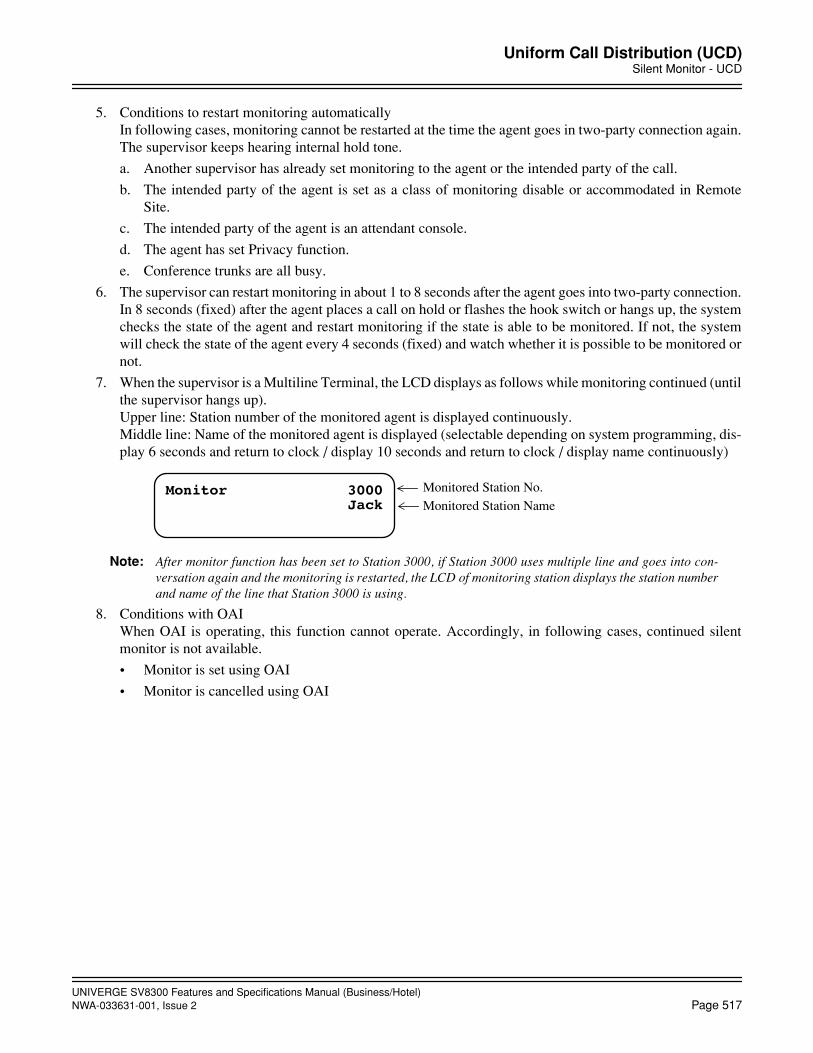
UNIVERGE SV8300 Features and Specifications Manual (Business/Hotel)NWA-033631-001, Issue 2 Page 517
Uniform Call Distribution (UCD)Silent Monitor - UCD
5. Conditions to restart monitoring automaticallyIn following cases, monitoring cannot be restarted at the time the agent goes in two-party connection again.The supervisor keeps hearing internal hold tone.
a. Another supervisor has already set monitoring to the agent or the intended party of the call.
b. The intended party of the agent is set as a class of monitoring disable or accommodated in RemoteSite.
c. The intended party of the agent is an attendant console.
d. The agent has set Privacy function.
e. Conference trunks are all busy.
6. The supervisor can restart monitoring in about 1 to 8 seconds after the agent goes into two-party connection.In 8 seconds (fixed) after the agent places a call on hold or flashes the hook switch or hangs up, the systemchecks the state of the agent and restart monitoring if the state is able to be monitored. If not, the systemwill check the state of the agent every 4 seconds (fixed) and watch whether it is possible to be monitored ornot.
7. When the supervisor is a Multiline Terminal, the LCD displays as follows while monitoring continued (untilthe supervisor hangs up).Upper line: Station number of the monitored agent is displayed continuously.Middle line: Name of the monitored agent is displayed (selectable depending on system programming, dis-play 6 seconds and return to clock / display 10 seconds and return to clock / display name continuously)
Note: After monitor function has been set to Station 3000, if Station 3000 uses multiple line and goes into con-versation again and the monitoring is restarted, the LCD of monitoring station displays the station numberand name of the line that Station 3000 is using.
8. Conditions with OAIWhen OAI is operating, this function cannot operate. Accordingly, in following cases, continued silentmonitor is not available.
• Monitor is set using OAI
• Monitor is cancelled using OAI
Monitor 3000 Monitored Station No.Monitored Station NameJack

UNIVERGE SV8300 Features and Specifications Manual (Business/Hotel)Page 518 NWA-033631-001, Issue 2
UMS8000 MailVoice Mail Live Record
UMS8000 Mail
Voice Mail Live Record
General Description
This feature allows a Multiline Terminal user to record the conversation with another station/trunk with VoiceMail System.
Station Application
All Multiline Terminals
Operating Procedure
To record conversation:
1. Press the Live Record Start key during two-party connection between stations or between station andtrunk.
2. The key lamp is flashing red while calling the voice mail.
3. The voice mail answers and recording is started. The key lamp lights on red.
To end recording:
1. Press the Live Record Start key again or press the Live Record End key during recording.
2. After the recoding ends, two-party is continuously connected. The key lamp goes off.
OR
1. The operating station goes on-hook.
2. The recording ends and the key lamp goes off.
To retrieve / delete / transfer the message:
1. Lift the handset and receive dial tone.
2. Dial the voice mail number and receive ring back tone.ORPress the Live Record Retrieve key. (No need to enter the voice mail number)
3. Follow the instructions given by voice mail.
Service Conditions
1. Active Voice voicemail (VM) system supporting extended AAINFO message is required.
2. Conditions of terminals operating “start recording”, “end recording” and “retrieve message” are as follows:
• These operations are available on Multiline Terminal, IP Multiline Terminal and SoftPhone.
• These operations are available from terminals in main site and remote site.
UNIVERGE SV8300 Features and Specifications Manual (Business/Hotel)NWA-033631-001, Issue 2 Page 519
UMS8000 MailVoice Mail Live Record
• These operations are unavailable on SLT, Attendant Console, PS, and ISDN terminal.
Conditions of recording operation [operating side]
1. Start of recording is available from two-party connection using any of my-line, sub-line and trunk key.
2. Recording is denied even during above two-party connection, under the following situation:
a) Call waiting is set for the station from other station/trunk
b) Camp-on is set for the station from other station/trunk
c) Whisper Page is set for the station from other station
d) The station is monitored from other station
e) Privacy Release is set for the station
f) During two-party connection with ISDN Terminal
g) During two-party connection with Attendant Console
3. After pressing the start key, if VM is not connected in a given amount of time (3 seconds; fixed) due to VMall port busy or VM failure for instance, the recording is denied.
4. Since Conference Trunk (CFT) is used when recording, if there is no vacant CFT, the recording is denied.
5. The VM-BOX number to which recorded conversation is registered by this feature is my-line number of thestation who did recording. Up to 8 digits is available as VM-BOX number.
6. Conditions of LCD display on Multiline TerminalWhen recording is started, the VM-BOX number and name are displayed.
Conditions during recording
1. During VM recording, operating station and its connected party cannot operate hold/transfer (hooking). Re-cording must be ended to operate hold/transfer.
2. Services during VM recording such as re-recording, pause, cancel are operable.
3. During recording, a confirmation tone that indicates “now recording” to the recording station and its con-nected party can be sent, if required. It can be set in system data programming.
Conditions to end recording
1. If a recording exceeds its maximum recording time, the recording is ended and the status is returned toformer two-party connection.
Conditions of retrieving message
1. The operation is available from my-line or sub-line.
2. When operating from sub-line, a user can retrieve message from VM-BOX for either “using sub-line num-ber” or “my-line number”.
Conditions of MW lamp/ LCD display on Multiline Terminal when registering live recorded message
1. The MW lamp service of recording Multiline Terminal can be set in system data programming.
2. “Message” can be displayed on the LCD of Multiline Terminal when any message for the station has beenstored in Voice Mail.

UNIVERGE SV8300 Features and Specifications Manual (Business/Hotel)Page 520 NWA-033631-001, Issue 2
UMS8000 MailVoice Mail Private Password
Voice Mail Private Password
General Description
Voice Mail Password can be prevented from displaying in LCD of Multiline Terminals when connected to theVoice Mail System.
Station Application
All Multiline Terminals with LCD
Operating Procedure
Normal password entry to VMS.
Service Conditions
1. When any connection to Voice Mail (VM) is established, each press of the Dial Key pad will display * ofthe LCD of Multiline Terminal.
2. This feature is assigned on a per tenant basis for VMS ports only.
UNIVERGE SV8300 Features and Specifications Manual (Business/Hotel)NWA-033631-001, Issue 2 Page 521
UMS8000 MailVoice Mail Transfer
Voice Mail Transfer
General Description
This feature has two functions that provide streamlined transfer access to voice mail.
1. One touch access to VMS
When an Attendant transfers an external call to a station, and if the station is busy or unanswered, theAttendant can transfer the call to a VMS by dialing “9” or by pressing a function key provided for thisfeature.
2. Transferring Camp-On call to VMS
When an Attendant sets Camp-On to a busy destination station for an external call, and if the destinationstation does not answer by predetermined time, the call can be automatically transferred to a VMS.
Station Application
All stations and Attendant Console
Operating Procedure
To transfer a call to a VMS with one touch access from a Single Line Telephone
1. While answering an external call, press FLASH key (or momentarily press the hook switch) and receive afeature dial tone.
2. Dial a desired station number and receive a busy tone.
3. Dial “9” or press a function key assigned for transferring a call to a VMS.
4. Restore the handset.
To transfer a call to a VMS with one touch access from a Multiline Terminal
1. While answering an external call, press Transfer key and receive a feature dial tone.
2. Dial a desired station number and receive a ringback tone or a busy tone.
3. Dial “9” or press a function key assigned for transferring a call to a VMS.
4. Restore the handset.
To transfer a call to a VMS with one touch access from an Attendant
1. While answering an external call, dial a desired station number and receive a ringback tone or a busy tone.
2. Dial “9” or press a function key assigned for transferring a call to a VMS.
3. Press the RELEASE key.

UNIVERGE SV8300 Features and Specifications Manual (Business/Hotel)Page 522 NWA-033631-001, Issue 2
UMS8000 MailVoice Mail Transfer
To transfer a Camp-on call from an Attendant to a VMS
1. While answering an external call, dial a desired station number and receive a busy tone.
2. Press the RELEASE key.
3. A Camp-On tone is sent and Camp-On is set.
4. If the Camp-On call is not answered by predetermined time, the call will be transferred automatically to theVMS.
5. Press the RELEASE key.
Service Conditions
1. If all ports in the VMS UCD group are busy (assuming the following conditions):
Station-A (or outside party)....Calling Party
Station-B....Called Party
Station-C....Destination of Call Transfer from Station-B.
Station-C does not set Call Forwarding - All Calls, Call Forwarding - Busy Line, or Call Forwarding - NoAnswer to the VMS.
Station-A (or outside party) calls Station B. Station-B presses Transfer key and dials Station-C.
a. Station-C is busy, Station-B hears Busy Tone (BUSY appears in display), and then presses VM transfer button (or dials 9).
• Station-A (or outside party) hears Music on Hold source.
• Station-B hears ROT and does not see CF BUSY in display as if it would if a VM port were avail-able. Station-B must press Transfer key to return to Calling Party.
b. Station-C is idle, Station-B hears Ringback Tone and presses VM transfer button (or dials 9).
• Station-A (or outside party) hears Music on Hold until Station-B goes on hook. When Station-Bgoes on hook, Station-A (or outside party) hears Ringback Tone.
• Station-B does not see CF NANS in display as if it would if a VM port were available, but Station-B sees Station-C number in display instead. If Station-B goes on hook, the call from Station-A (oroutside party) is transferred to Station-C and continues to ring at Station-C until Station TransferRecall occurs. The call will return to Station-B.
2. If all ports in the VMS UCD group are busy (assuming the following conditions):
Station-A (or outside party)....Calling Party
Attendant Console....Called Party
Station-C....Destination of Call Transfer from Attendant Console.
Station-C does not set Call Forwarding - All Calls, Call Forwarding - Busy Line, or Call Forwarding - NoAnswer to the VMS.
Station-A (or outside party) calls Attendant Console. Attendant Console dials Station-C.
a. Station-C is busy, Attendant Console hears Busy Tone (BUSY appears in display), and then presses VM transfer button.
• Station-A (or outside party) hears Music on Hold source.

UNIVERGE SV8300 Features and Specifications Manual (Business/Hotel)NWA-033631-001, Issue 2 Page 523
UMS8000 MailVoice Mail Transfer
• Attendant Console does not see CF BUSY in display as if it would if a VM port were available. IfAttendant presses RLS key, the call will Camp-on to Station-C. If it is allowed in system program-ming and a VM port becomes available, the Calling Party will automatically transfer to the VMSwhen the Attendant Camp-on Recall timer occurs. If no VM port is available or if VMS Transferwith Camp-on is not allowed, the Calling Party will call the Attendant Console again when the At-tendant Recall timer occurs.
b. Station-C is idle, Attendant Console hears Ringback Tone and presses VM transfer button.
• Station-A (or outside party) hears Music on Hold until Attendant Console presses RLS key. WhenAttendant Console presses RLS key, Station-A (or outside party) hears Ringback Tone.
• Attendant Console does not see CF NANS in display as if it would if a VM port were available, butAttendant Console sees Station-C number in display instead. If Attendant Console presses RLSkey, the call from Station-A (or outside party) is transferred to Station-C and continues to ring atStation-C until Attendant Transfer Recall occurs. The call will return to Attendant Console.
3. Transferring Camp-on calls to VMS is available only from Attendant Consoles.
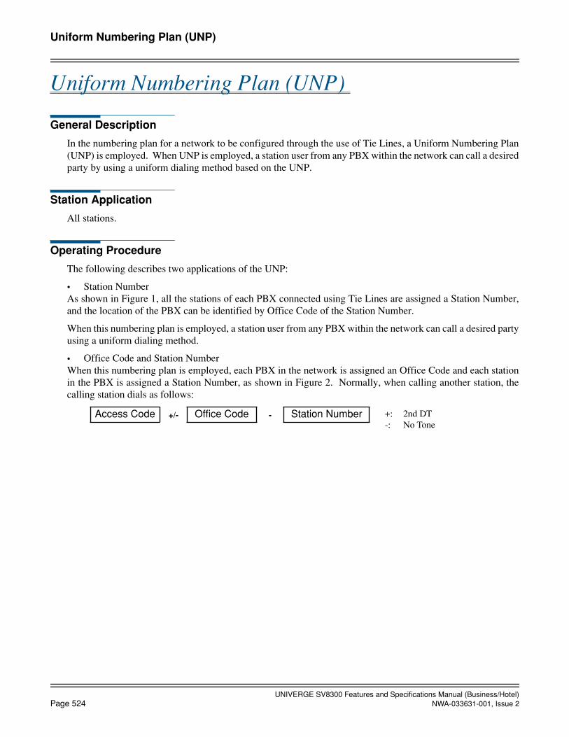
UNIVERGE SV8300 Features and Specifications Manual (Business/Hotel)Page 524 NWA-033631-001, Issue 2
Uniform Numbering Plan (UNP)
Uniform Numbering Plan (UNP)
General Description
In the numbering plan for a network to be configured through the use of Tie Lines, a Uniform Numbering Plan(UNP) is employed. When UNP is employed, a station user from any PBX within the network can call a desiredparty by using a uniform dialing method based on the UNP.
Station Application
All stations.
Operating Procedure
The following describes two applications of the UNP:
• Station NumberAs shown in Figure 1, all the stations of each PBX connected using Tie Lines are assigned a Station Number,and the location of the PBX can be identified by Office Code of the Station Number.
When this numbering plan is employed, a station user from any PBX within the network can call a desired partyusing a uniform dialing method.
• Office Code and Station NumberWhen this numbering plan is employed, each PBX in the network is assigned an Office Code and each stationin the PBX is assigned a Station Number, as shown in Figure 2. Normally, when calling another station, thecalling station dials as follows:
Access Code +/- Office Code - Station Number +: 2nd DT-: No Tone
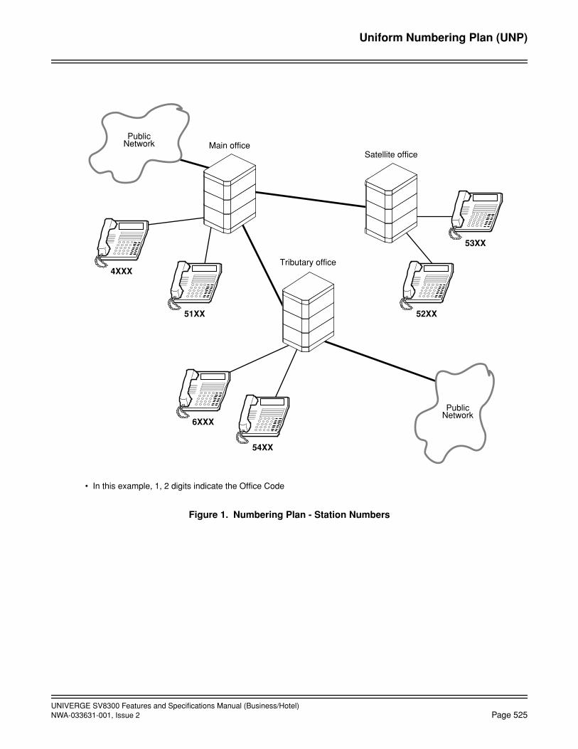
UNIVERGE SV8300 Features and Specifications Manual (Business/Hotel)NWA-033631-001, Issue 2 Page 525
Uniform Numbering Plan (UNP)
Figure 1. Numbering Plan - Station Numbers
• In this example, 1, 2 digits indicate the Office Code
Main officeSatellite office
Tributary office
PublicNetwork
PublicNetwork
4XXX
51XX
6XXX
54XX
52XX
53XX
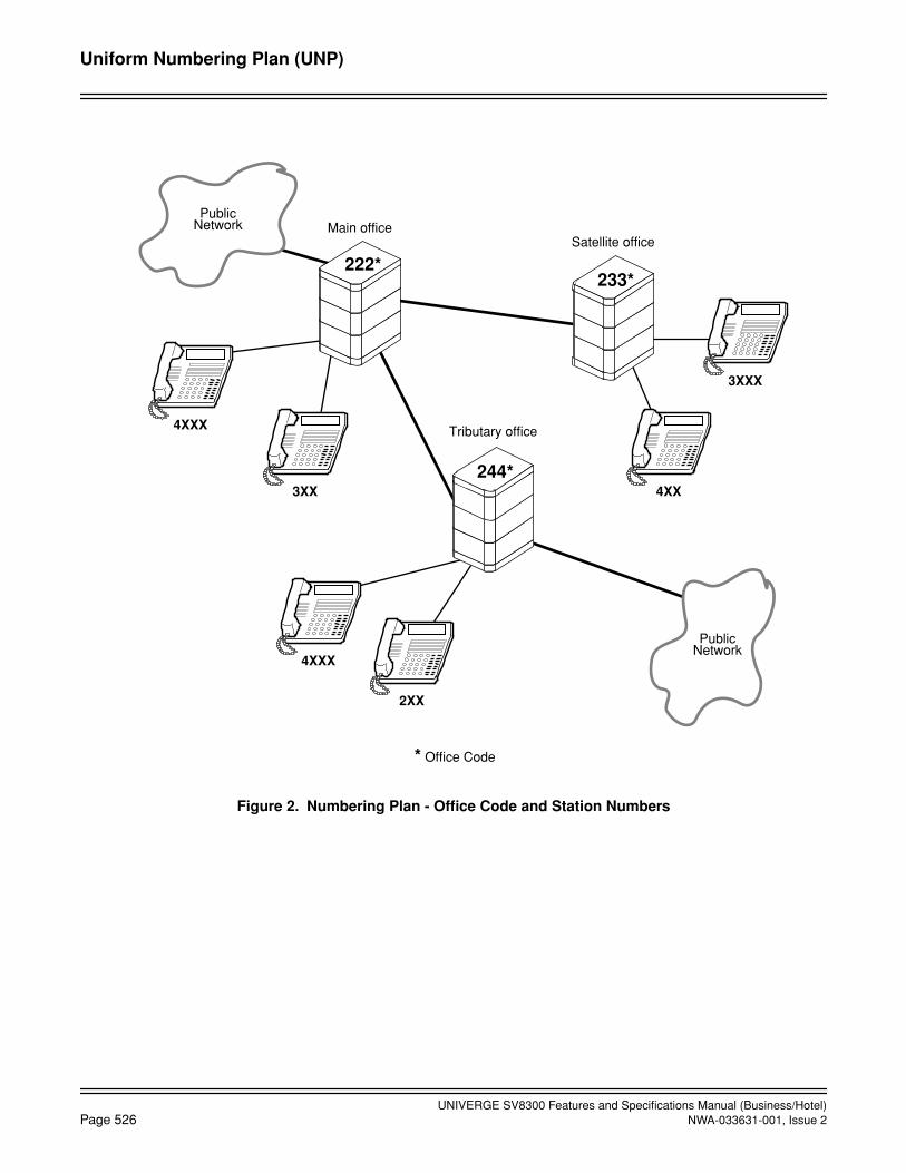
UNIVERGE SV8300 Features and Specifications Manual (Business/Hotel)Page 526 NWA-033631-001, Issue 2
Uniform Numbering Plan (UNP)
Figure 2. Numbering Plan - Office Code and Station Numbers
* Office Code
Main officeSatellite office
Tributary office
PublicNetwork
PublicNetwork
4XXX
3XX
4XXX
2XX
4XX
3XXX
222*233*
244*
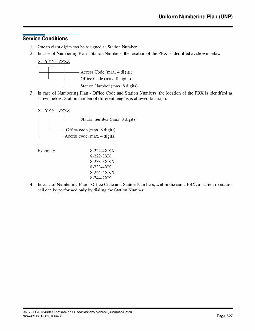
UNIVERGE SV8300 Features and Specifications Manual (Business/Hotel)NWA-033631-001, Issue 2 Page 527
Uniform Numbering Plan (UNP)
Service Conditions
1. One to eight digits can be assigned as Station Number.
2. In case of Numbering Plan - Station Numbers, the location of the PBX is identified as shown below.
3. In case of Numbering Plan - Office Code and Station Numbers, the location of the PBX is identified asshown below. Station number of different lengths is allowed to assign.
Example: 8-222-4XXX8-222-3XX8-233-3XXX8-233-4XX8-244-4XXX8-244-2XX
4. In case of Numbering Plan - Office Code and Station Numbers, within the same PBX, a station-to-stationcall can be performed only by dialing the Station Number.
X - YYY - ZZZZ
Access Code (max. 4 digits)
Office Code (max. 8 digits)
Station Number (max. 8 digits)
X - YYY - ZZZZ
Station number (max. 8 digits)
Office code (max. 8 digits)Access code (max. 4 digits)

UNIVERGE SV8300 Features and Specifications Manual (Business/Hotel)Page 528 NWA-033631-001, Issue 2
Variable Timing Parameters
Variable Timing Parameters
General Description
This feature gives the system the versatility to change timing duration using the PCPro or the Customer Admin-istration Terminal (CAT). These timing parameters can be changed according to the customer's requirements.
Station Application
Not applicable.
Operating Procedure
Refer to the Programming Manual for programming instructions.
Service Conditions
The Programming Manual contains instructions on how to change the following timing durations:
Parameter
Duration (in seconds unless otherwise marked)
Standard timing Variable timing
Automatic Recall of Attendant transferred Camp-On and unanswered calls
31.2 - 33.60.0 - 124.8 (2.4-second increments in 2.4 - 33.6 seconds
9.6-second increments in 28.8 - 124.8 seconds)
Elapsed time before Call Forwarding - No Answer for incoming trunk calls or Atten-dant Overflow activation
32 - 36 0 - 120 (4-second increments)
Station Message Detail Recording (SMDR) valid call timer
20 - 24 8 - 40
Disconnect recognition time for trunks 0.96 - 1.44 0 - 6.72 (0.48-second increments)
Recall timing for Exclusive Hold 236 - 240 0 - 396 (4-second increments)
Recall timing for Nonexclusive Hold and Call Park
60 - 64 0 - 396 (4-second increments)
Recall timing after station release for Call Transfer
24 - 28 0 - 120 (4-second increments)
Periodic Time Indication Tone interval 180 - 184 32 - 724 (60-second increments)
Automatic cancel time for unanswered external paging calls
300 60-900 (60-second increments)
Reorder tone timeout to enter Line Lock-out state and Off-Hook Alarm
28-32 4 to 32 (4-second increments)
Ringing duration of Automatic Wake Up call (Timed Reminder)
28-32 0 - 32 (4-second increments)
Single digit dialing timer (Timing Start) 4-5 2-8 (1-second increments)
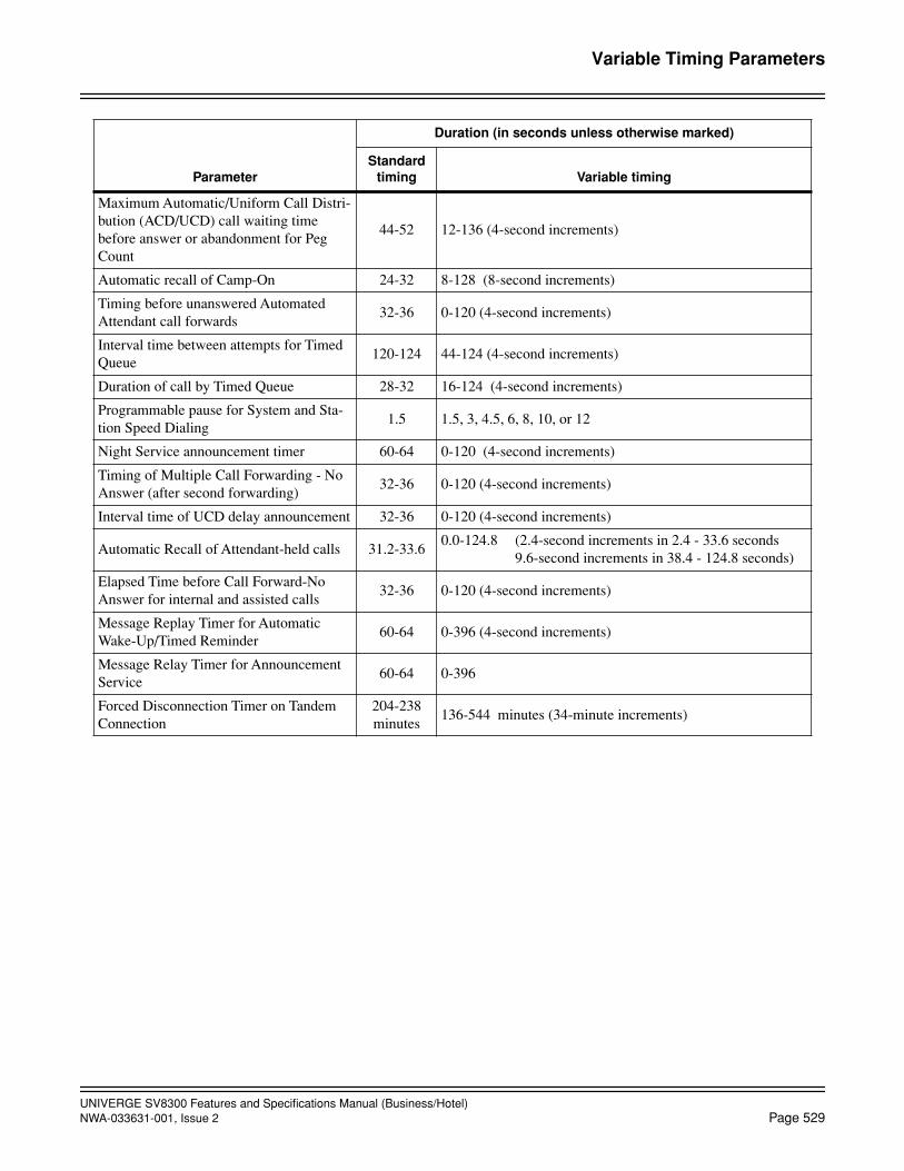
UNIVERGE SV8300 Features and Specifications Manual (Business/Hotel)NWA-033631-001, Issue 2 Page 529
Variable Timing Parameters
Maximum Automatic/Uniform Call Distri-bution (ACD/UCD) call waiting time before answer or abandonment for Peg Count
44-52 12-136 (4-second increments)
Automatic recall of Camp-On 24-32 8-128 (8-second increments)
Timing before unanswered Automated Attendant call forwards
32-36 0-120 (4-second increments)
Interval time between attempts for Timed Queue
120-124 44-124 (4-second increments)
Duration of call by Timed Queue 28-32 16-124 (4-second increments)
Programmable pause for System and Sta-tion Speed Dialing
1.5 1.5, 3, 4.5, 6, 8, 10, or 12
Night Service announcement timer 60-64 0-120 (4-second increments)
Timing of Multiple Call Forwarding - No Answer (after second forwarding)
32-36 0-120 (4-second increments)
Interval time of UCD delay announcement 32-36 0-120 (4-second increments)
Automatic Recall of Attendant-held calls 31.2-33.60.0-124.8 (2.4-second increments in 2.4 - 33.6 seconds
9.6-second increments in 38.4 - 124.8 seconds)
Elapsed Time before Call Forward-No Answer for internal and assisted calls
32-36 0-120 (4-second increments)
Message Replay Timer for Automatic Wake-Up/Timed Reminder
60-64 0-396 (4-second increments)
Message Relay Timer for Announcement Service
60-64 0-396
Forced Disconnection Timer on Tandem Connection
204-238 minutes
136-544 minutes (34-minute increments)
Parameter
Duration (in seconds unless otherwise marked)
Standard timing Variable timing

UNIVERGE SV8300 Features and Specifications Manual (Business/Hotel)Page 530 NWA-033631-001, Issue 2
Voice Guide
Voice Guide
General Description
This feature provides a station user with an announcement that informs;
1. In stead of service set tone, the feature is successfully set or canceled during the operation.
2. In stead of special dial tone, following feature is active on the user’s telephone set when the user lifts thehandset.
• Call Forwarding - All Calls
• Do Not Disturb
• Message Waiting indication
Station Application
All stations.
Operating Procedure
No manual operation is required.
Service Conditions
Announcements when the feature is successfully set or canceled
1. The announcement is provided when the following service features are set or canceled.
• Call Forwarding - All Calls/Busy Line/No Answer
• Split Call Forwarding - All Calls/Busy Line/No Answer
• Do Not Disturb
• UCD - Busy Out Note• Station Message Schedule Display
• Call BackNote: The announcement can be provided only when the UCD - Busy Out feature is set or canceled by dialing the
feature access code. When the feature is set or canceled by pressing the Busy - Out feature key, the an-nouncement is not provided (service set tone is provided).
2. Two announcements are provided for all the above features: one tells the feature is successfully set and an-other tells the feature is successfully canceled. Different announcements cannot be provided on a featurebasis.
3. This feature requires a built-in Voice Response System (VRS). The announcement messages are requiredto record from the telephone set.
4. Multiple stations may be connected to one VRS port at the same time. Only the first station can be assuredof hearing the message from the beginning.
5. After the announcement is provided, the station user will hear reorder tone. The duration of announcementis specified by the system data programming.

UNIVERGE SV8300 Features and Specifications Manual (Business/Hotel)NWA-033631-001, Issue 2 Page 531
Voice Guide
6. This service is effective on the system-wide basis.
7. DT700 does not support this feature.
Announcements when Call Forwarding - All Calls, Do Not Disturb or Message Waiting indication is active
1. Two announcements can be provided for station users in the following status lift the handset.
• Call Forwarding - All Calls, Split Call Forwarding - All Calls or Do Not Disturb has been set on theuser’s telephone set.
• Message Waiting or Message Reminder has been set on the user’s telephone set.
When both Call Forwarding/Do Not Disturb and Message Waiting/Message Reminder feature has been setfor the station, the announcement for Message Waiting/Message Reminder is provided.
2. This feature requires a built-in Voice Response System (VRS). The announcement messages are requiredto record from the telephone set.
3. Multiple stations may be connected to one VRS port. Only the first station can be assured of hearing themessage from the beginning.
4. This service is effective on the system-wide basis.
5. A station can originate a call while receiving the announcement.
6. DT700 does not support this feature.
UNIVERGE SV8300 Features and Specifications Manual (Business/Hotel)Page 532 NWA-033631-001, Issue 2
Voice Mail Integration (Analog)
Voice Mail Integration (Analog)
General Description
This feature is used to connect the system with a locally-provided stand-alone type Voice Mail System (VMS).The VMS, connected to the system single line circuit (LC), is controlled by sending/receiving DTMF signalsusing this LC.
The VMS's voice mail feature can be used by accessing this VMS directly from an extension. If a station setsits call forwarding destination to the VMS, calls to this station are connected to the VMS, and the messages canbe registered according to the VMS instruction. In addition, the Message Waiting lamp of the station can beturned on automatically by the VMS.
Station Application
All stations.
Operating Procedure
To originate a voice mail message
From a Single Line Telephone
1. Go off hook and receive dial tone.
2. Dial the voice mail extension number and receive ringback tone.
3. Follow the instructions given by the VMS.
From a Multiline Terminal with One Touch keys
1. Go off hook and receive dial tone.
2. Press the One Touch key, to send “Voice Mail extension number + DTMF signal after the Voice Mail Sys-tem answered (such as mail box number or password)”.
3. Follow the instructions given by the VMS.
To set call forwarding to a voice mail system
• Call Forwarding - All Calls• Call Forwarding - Busy Line• Call Forwarding - No Answer
1. Go off hook and receive dial tone.
2. Dial the call forwarding feature access code and receive feature dial tone.
3. Dial the voice mail extension number and receive service set tone.
4. The LCD displays:
[SET xxxx]
VMS: Voice mail extension number

UNIVERGE SV8300 Features and Specifications Manual (Business/Hotel)NWA-033631-001, Issue 2 Page 533
Voice Mail Integration (Analog)
Connection when an extension line number whose call forwarding is set to a voice mail system is called from another station
1. Go off hook and receive dial tone.
2. Dial the desired station number and receive ringback tone. The LCD displays:
[CF ALL xxx]
VMS: Voice mail extension number
3. Follow the instructions given by the VMS.
To retrieve a voice mail message from the voice mail system
1. Go off hook and receive dial tone.
2. Dial the voice mail extension number or the Message Waiting/Message Reminder retrieve code and receiveringback tone. The LCD displays:
[ xxx]
VMS: Voice mail extension number
3. Follow the instructions given by the VMS.
Service Conditions
1. The VMS is interfaced to the system through the LC blade. (The LC blade provides disconnect supervisionin the form of a momentary loop open.)
2. The system transfers only DTMF signals to the connected VMS. It cannot transfer dial pulses to the system.
3. Messages can be retrieved from any Multiline Terminal, DTMF telephone, or the Attendant Console, butnot from DP telephones.
4. When the calling party is connected to the Voice Mail System, only DTMF signals can be sent to the VMSfor registering a message. DP telephones cannot be used.
5. Stations can set Call Forwarding - All Calls, Call Forwarding - No Answer, and Call Forwarding - BusyLine to the VMS. The system sends out a mail box number to the VMS. Calling a station that has Call For-warding set to the VMS is automatically answered by the VMS.
6. The DTMF signal pause, Inter-Digit Pause, and DTMF signal width of the station number automaticallysent out to the VMS from the system are as follows:
• Pause: Variable from 1 second to 12 seconds in 1 second increments
• Inter-Digit Pause: Variable from 32 milliseconds to 240 milliseconds
• DTMF signal width: Fixed at 64 milliseconds or 128 milliseconds
7. A special number of up to 4 digits (including an Inter-Digit Pause) can automatically be added, both beforeand after, to the station number that is sent to the VMS from the system. This can be used for a variety ofidentification codes as required. Two types of Inter-Digit Pauses can be set per system. One is fixed at 1.5seconds, and the other is programmable from 1.5 seconds to 16 seconds.
8. The VMS can control the Message Waiting Lamp of the Station set by using the Message Waiting/MessageReminder feature. The retrieval access code for Message Waiting/Message Reminder is variable and can beset from 1 to 4 digits, in system programming.
9. When all VMS is busy (assuming the following condition):
Station-A (or outside party)....Calling Party
Station-B....Called Party

UNIVERGE SV8300 Features and Specifications Manual (Business/Hotel)Page 534 NWA-033631-001, Issue 2
Voice Mail Integration (Analog)
Station-B sets Call Forwarding - All Calls/Busy Line/No Answer to the VMS.
Station-A (or outside party) makes a call to Station-B.
a. Call Forwarding - All Calls
• Station A hears reorder tone.
• Outside party hears busy tone.
b. Call Forwarding - Busy Line
• Station-A hears busy tone, and can set any busy service to station-B.
• Outside party hears busy tone.
c. Call Forwarding - No Answer
• Station-B continues to ring until the VMS becomes idle regardless of whether the predeterminedtime for Call Forwarding - No Answer has elapsed. When the VMS becomes idle, Station-A is con-nected to the VMS.
d. Direct access to VMS
• If station-A or outside party accesses the VMS directly, the calling party hears busy tone. Station-A can set call back to the VMS.
10. Multiple Call Forwarding to VMS: When the final destination for any combination of Multiple Call For-warding is the VMS, calls can be transferred to the VMS. The first forwarded station's number (forwardedto the VMS) is sent to the VMS. For example, a call is received by Station A, which is forwarded to Station-B, which is forwarded to Station-C, which is forwarded to VMS. The number of Station-A is sent to theVMS.
11. Ringing Transfer to an Attendant via the VMS: The system allows the VMS to transfer the station or outsideparty to the Attendant and releases before the Attendant answers.
12. When the VMS is recalled, by transferring the call to an unanswered station, the system may be pro-grammed to send the recalling extension number to the VMS.
13. A maximum of 26 digit extension numbers including DTMF signal after the VMS answered, can be pro-grammed to a One Touch key of a Multiline Terminal.

UNIVERGE SV8300 Features and Specifications Manual (Business/Hotel)NWA-033631-001, Issue 2 Page 535
VoIP Log Collection
VoIP Log Collection
General Description
This feature provides Voice over IP (VoIP) log collection functions for analyzing VoIP related problems causedby IP device, usage method, network environment and other effects. A maintenance person will be able to un-derstand its cause and figure out how to solve the problem. The following functions are supported.
• Call Log CollectionIt enables the collected call log to be checked when the user reports a malfunction. Call log is output to theRS port of CPU. It includes the speech time, number of sent/received packets and number of received pack-ets lost.
Operational example and outline of call log collection
• Fault Log CollectionIt enables a real time check when a malfunction exists at registration or checking of accumulated fault in-formation by a maintenance person. Fault log is output to the RS port of CPU. It includes reset cause andreset time, number of sent/received control packets, number of resent control packets, number of controlpackets that fails to resend, number of abnormal control packets received and number of times control se-quence becomes abnormal.

UNIVERGE SV8300 Features and Specifications Manual (Business/Hotel)Page 536 NWA-033631-001, Issue 2
VoIP Log Collection
Operational example and outline of fault log collection
Station Application
IP Multiline Terminal (Dterm Series i with IP adapter, DtermIP INASET, SP30 Softphone with applicable firm-ware version)
Operating Procedure
No manual operation is required.
Service Conditions
General Conditions
1. This feature supports following IP telephone and VoIPDB with applicable firmware:
X: Available-: Not available
VoIP Device Availability Firmware Version
Dterm Series i IP adapter X 2.80 or later
Dterm Series i Integrated type X 2.80 or later
Dterm INASET240G X E02.80 or later
Dterm SP20 -
SP30 Softphone X Ver.7.3.0.0 or later
Dterm Series E IP adapter -
VoIPDB X

UNIVERGE SV8300 Features and Specifications Manual (Business/Hotel)NWA-033631-001, Issue 2 Page 537
VoIP Log Collection
2. The accumulated call log and fault log can be output via RS232C (RS port of the CPU) to a PC. This intendsto capture the log in a text file by a PC. For the record format at the time, see the Maintenance Manual. Tooutput the log data, communication software such as Hyper Terminal must be installed in a PC. Note thatPC Programming via RS232C connection cannot be used during using the communication software.
Note: When Hyper Terminal is used, select “file” then “property”, and set the emulation to VT100.
3. During call log/fault log collection, be sure to set the CPU to online mode.
Conditions for Call Log Collection
1. The call log is collected when a call ends. No call log can be collected when connection fails.
2. The speech time in the call log is calculated from the call start time and the call end time that each VoIPdevice maintains. The time may not match with the system time. For example, if the system time is updatedduring a call, the call start time is recorded using the time before the update, but the call end time is recordedusing the time after the update.
3. If a station transfers a call to another station while the call is in progress, those calls are collected separatelyin the call log. For example, if station B makes consultation hold with station A, and transfers the call tostation C, and hangs up, the call log between station A and station B, and the call log between station B andstation C are collected separately.
4. The number of sent packets in the call log is the number of voice packets that the device sends in the payloadsize instructed from the PBX.
5. The number of received packets in the call log is the number of voice packets in the payload size receivedfrom a connected VoIP device.
6. The number of received packets lost in the call log is a difference from the number of voice packets thatwould have been received normally.
7. If the call log cannot be output to the RS port of the CPU due to communication disconnection, the call logsfor up to 256 records are accumulated in the CPU. After accumulated up to the maximum, it is selectablewhether to overwrite a new call log by system data programming.
8. Since the accumulated call log in the CPU is not backed up, it is deleted when system initialization is per-formed.
UNIVERGE SV8300 Features and Specifications Manual (Business/Hotel)Page 538 NWA-033631-001, Issue 2
VoIP Log Collection
Conditions for Fault Log Collection
1. The fault log is collected at either of the following timing.
- When a terminal registration is completed or VoIPDB becomes online
- When a fault log collection is executed by PCPro/CAT
2. When a terminal registration is completed or VoIPDB becomes online, fault information: FK = 49 of PCProgramming can be registered based on the reset cause received as a fault log. A fault is registered on aterminal basis for an IP phone, on a blade basis for VoIPDB. A fault is registered only when the reset causeis “autonomous reset.” It is not registered when the reset is caused by “logout operation”.
3. Fault logs are collected by one VoIP device for every four seconds at the shortest time. If multiple requestsare made for a short time, logs for eight devices wait but further devices are discarded.
4. Fault logs can be collected only in the following state:
- During an IP phone logins to PBX
- During an VoIPDB is online state
5. The reset execution time in the fault log is calculated from the time each VoIP device maintains. The timemay not match with the system time.

UNIVERGE SV8300 Features and Specifications Manual (Business/Hotel)NWA-033631-001, Issue 2 Page 539
Whisper Page
Whisper Page
General Description
This feature allows a secretary to interrupt the boss in a private way. By pressing a feature key or dialing anAccess Code, the secretary station can interrupt the conversation between the boss and another party (station ortrunk). When the conversation is interrupted, the boss can hear the secretary but the other party is unaware ofthe Voice Override.
Station Application
All stations.
Operating Procedure
To activate Whisper Page (1) from a Single Line Telephone or a Multiline Terminal
1. Receive Busy Tone after dialing the boss station.
2. Press the FLASH key (momentarily press the hook switch) or press the Transfer key.
3. Receive feature dial tone.
4. Dial the Whisper Page access code or press the Whisper Page feature key
5. Service set tone is heard. You can hear the conversation and speak to the boss station that you called.
To activate Whisper Page (2) from a Single Line Telephone or a Multiline Terminal)
1. Lift the handset or press the Speaker key, and receive dial tone.
2. Dial the Whisper Page access code or press the Whisper Page feature key.
3. Receive feature dial tone.
4. Dial the boss station number.
5. Service set tone is heard. You can hear the conversation and speak to the boss station that you called, evenif the boss station has set Call Forwarding - Busy Line.
See Service Conditions for Operating Procedure (2) for details.
To answer Whisper Page from a Multiline Terminal
1. The called party (the boss) presses the Answer key while the whisper page is in progress, the original callis put on hold.A holding tone is not transmitted to the other party of the original call.
2. The called station can then privately talk to the calling station (the secretary).
3. The called station presses the Answer key again.
4. The called station will return to the original call, while the calling station is put on hold.
If the called station (the boss) hangs up while the Whisper Page is in progress, the original call will be released.Then a Ringback Tone is transmitted to the calling station and the called station can hear a ringing tone.
If the calling station (the secretary) or the other party of the original call hangs up while the Whisper Page is in

UNIVERGE SV8300 Features and Specifications Manual (Business/Hotel)Page 540 NWA-033631-001, Issue 2
Whisper Page
progress, the call turns into a two-party connection.
Service Conditions
1. The station user (the secretary) can set only one station (boss) that can interrupt by Whisper Page. If thesecretary station tries to override to other stations, the secretary will hear Reorder Tone.
2. The called station (the boss) must be a Multiline Terminal.
3. This feature enables a maximum of 16 stations to access simultaneously including the other conference fea-tures.
4. The calling station and the called station can be defined as the Service Restriction Class.
5. Whisper Page cannot be made from or to an Attendant Console.
6. Whisper Page cannot be set to a station which is calling from an Attendant Console or a station which is seton Privacy.
7. Whisper Page can be set to a call in progress with the primary extension, Sub Line, or trunk line appearance.
8. Whisper Page cannot be set to a call in progress with the Sub Line to which Camp-On has been set.
9. The called station number (name) in conversation is displayed on LCD of the calling station.
Service Conditions for Operating Procedure (2)
1. The same operating procedure is available for the Sub Line of a Multiline Terminal.
2. Whisper Page is used when the called station is busy. If the called station is idle, the ringing is sent to thecalled station normally.
3. When the called station has set Call Forwarding - All Calls/Do Not Disturb, and is busy, Whisper Page isavailable. If the called station is idle, the Call Forwarding - All Calls/Do Not Disturb is activated.

UNIVERGE SV8300 Features and Specifications Manual (Business/Hotel)NWA-033631-001, Issue 2 Page 541
October, 2008
Feature Availability Chart
SV8300 Features(Global Feature Name)
Applicable Market IPS SV8300
US EU LASC AUST ASIA R14 R1 R2
Account Code X X X X X X X X
Add-On Module X X X X X X X X
Alarm Indications X X X X X X X X
Alphanumeric Display X X X X X X X X
Announcement Service X X X X X X X X
Answer Key X X X X X X X X
Attendant Assisted Calling X X X X X X — X
Attendant Camp-On X X X X X X — X
Attendant Console X X X X X X — X
Attendant Called/Calling Name Display X X X X X X — X
Attendant Called/Calling Number X X X X X X — X
Attendant Call Selection X X X X X X — X
Attendant Console Lockout - Password X X X X X X — X
Attendant Do Not Disturb Setup and Cancel X X X X X X — X
Attendant Interposition Calling/Transfer X X X X X X — X
Attendant Lamp Check X X X X X X — X
Attendant Listed Directory Number X X X X X X — X
Attendant Loop Release X X X X X X — X
Attendant Programming X X X X X X — X
Attendant Training Jacks X X X X X X — X
Audible Indication Control X X X X X X — X
Call Processing Indication X X X X X X — X
Call Queuing X X X X X X — X
Call Splitting X X X X X X — X
Call Waiting Display X X X X X X — X
Common Route Indial X X X X X X — X
Dialed Number Identification Service (DNIS) X X X X X X — X
Incoming Call Identification X X X X X X — X
Individual Trunk Access X X X X X X — X
Multi-Function Key X X X X X X — X
Multiple Console Operation X X X X X X — X
Pushbutton Calling - Attendant Only X X X X X X — X
Serial Call X X X X X X — X
Time Display X X X X X X — X
Trunk Group Busy Display X X X X X X — X
Unsupervised Trunk-to-Trunk Transfer By Attendant
X X X X X X — X
X = available D=discontinued— = not availableE = enhanced or changed→ = carried over to next level software
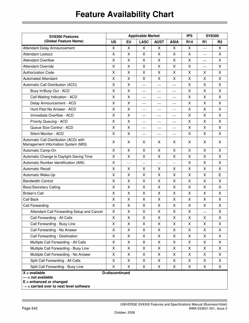
UNIVERGE SV8300 Features and Specifications Manual (Business/Hotel)Page 542 NWA-033631-001, Issue 2
October, 2008
Feature Availability Chart
Attendant Delay Announcement X X X X X X — X
Attendant Lockout X X X X X X — X
Attendant Overflow X X X X X X — X
Attendant Override X X X X X X — X
Authorization Code X X X X X X X X
Automated Attendant X X X X X X X X
Automatic Call Distribution (ACD) X X — — — X X X
Busy In/Busy Out - ACD X X — — — X X X
Call Waiting Indication - ACD X X — — — X X X
Delay Announcement - ACD X X — — — X X X
Hunt Past No Answer - ACD X X — — — X X X
Immediate Overflow - ACD X X — — — X X X
Priority Queuing - ACD X X — — — X X X
Queue Size Control - ACD X X — — — X X X
Silent Monitor - ACD X X — — — X X X
Automatic Call Distribution (ACD) with Management Information System (MIS)
X X X X X X X X
Automatic Camp-On X X X X X X X X
Automatic Change to Daylight Saving Time X X X X X X X X
Automatic Number Identification (ANI) X — — — — X X X
Automatic Recall X X X X X X X X
Automatic Wake-Up X X X X X X X E
Bandwidth Control X X X X X X X X
Boss/Secretary Calling X X X X X X X X
Broker’s Call X X X X X X X X
Call Back X X X X X X X X
Call Forwarding X X X X X X X X
Attendant Call Forwarding Setup and Cancel X X X X X X — X
Call Forwarding - All Calls X X X X X X X X
Call Forwarding - Busy Line X X X X X X X X
Call Forwarding - No Answer X X X X X X X X
Call Forwarding - Destination X X X X X X X X
Multiple Call Forwarding - All Calls X X X X X X X X
Multiple Call Forwarding - Busy Line X X X X X X X X
Multiple Call Forwarding - No Answer X X X X X X X X
Split Call Forwarding - All Calls X X X X X X X X
Split Call Forwarding - Busy Line X X X X X X X X
SV8300 Features(Global Feature Name)
Applicable Market IPS SV8300
US EU LASC AUST ASIA R14 R1 R2
X = available D=discontinued— = not availableE = enhanced or changed→ = carried over to next level software

UNIVERGE SV8300 Features and Specifications Manual (Business/Hotel)NWA-033631-001, Issue 2 Page 543
October, 2008
Feature Availability Chart
Split Call Forwarding - No Answer X X X X X X X X
Call Forwarding - Logout X X X X X X X X
Call Forwarding - Override X X X X X X X X
Group Diversion X X X X X X X X
Call History X X X X X X E X
Incoming Call History (CID Call Back) X X X X X X E X
Outgoing Call History (Stack Dial) X X X X X X E X
Call Park X X X X X X X X
Call Park - System X X X X X X X X
Call Park - Tenant X X X X X X X X
Call Pickup X X X X X X X X
Call Pickup - Direct X X X X X X X X
Call Pickup - Group X X X X X X X X
Call Pickup - Designated Group X X X X X X X X
Call Redirect X X X X X X X X
Call Transfer X X X X X X X X
Call Transfer - All Calls X X X X X X X X
Call Transfer - Attendant X X X X X X — X
Caller ID X X X X X X X X
Caller ID Class X — — — X X X X
Caller ID Display X X X X X X X X
Caller ID - Station X — — — X X X X
Caller ID - Station (ETSI - FSK) — X — — — X X X
CID Call Routing X X X X X X X X
No CID Call Routing X X X X X X X X
Camp-On / Call Waiting X X X X X X X X
Centrex Compatibility X — — — — X X X
Check In/Check Out X X X X X X X X
Class of Service X X X X X X X X
Code Restriction X X X X X X X X
Conference (Three/Four Party) X X X X X X X X
Conference (32 Party) X X X X X X — X
Group Call X X X X X X — X
Meet-Me Conference X X X X X X — X
Consecutive Speed Dialing X X X X X X X X
Consultation Hold X X X X X X X X
Customer Administration Terminal (CAT) X X X X X X X X
SV8300 Features(Global Feature Name)
Applicable Market IPS SV8300
US EU LASC AUST ASIA R14 R1 R2
X = available D=discontinued— = not availableE = enhanced or changed→ = carried over to next level software
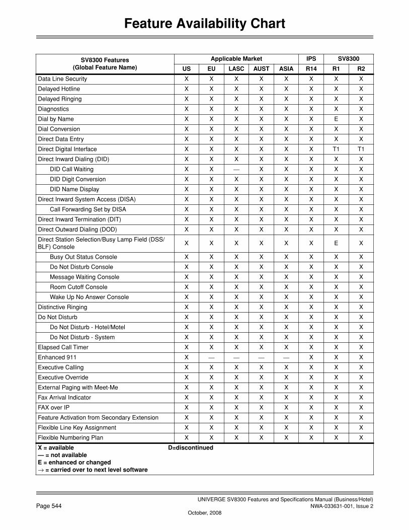
UNIVERGE SV8300 Features and Specifications Manual (Business/Hotel)Page 544 NWA-033631-001, Issue 2
October, 2008
Feature Availability Chart
Data Line Security X X X X X X X X
Delayed Hotline X X X X X X X X
Delayed Ringing X X X X X X X X
Diagnostics X X X X X X X X
Dial by Name X X X X X X E X
Dial Conversion X X X X X X X X
Direct Data Entry X X X X X X X X
Direct Digital Interface X X X X X X T1 T1
Direct Inward Dialing (DID) X X X X X X X X
DID Call Waiting X X — X X X X X
DID Digit Conversion X X X X X X X X
DID Name Display X X X X X X X X
Direct Inward System Access (DISA) X X X X X X X X
Call Forwarding Set by DISA X X X X X X X X
Direct Inward Termination (DIT) X X X X X X X X
Direct Outward Dialing (DOD) X X X X X X X X
Direct Station Selection/Busy Lamp Field (DSS/ BLF) Console
X X X X X X E X
Busy Out Status Console X X X X X X X X
Do Not Disturb Console X X X X X X X X
Message Waiting Console X X X X X X X X
Room Cutoff Console X X X X X X X X
Wake Up No Answer Console X X X X X X X X
Distinctive Ringing X X X X X X X X
Do Not Disturb X X X X X X X X
Do Not Disturb - Hotel/Motel X X X X X X X X
Do Not Disturb - System X X X X X X X X
Elapsed Call Timer X X X X X X X X
Enhanced 911 X — — — — X X X
Executive Calling X X X X X X X X
Executive Override X X X X X X X X
External Paging with Meet-Me X X X X X X X X
Fax Arrival Indicator X X X X X X X X
FAX over IP X X X X X X X X
Feature Activation from Secondary Extension X X X X X X X X
Flexible Line Key Assignment X X X X X X X X
Flexible Numbering Plan X X X X X X X X
SV8300 Features(Global Feature Name)
Applicable Market IPS SV8300
US EU LASC AUST ASIA R14 R1 R2
X = available D=discontinued— = not availableE = enhanced or changed→ = carried over to next level software
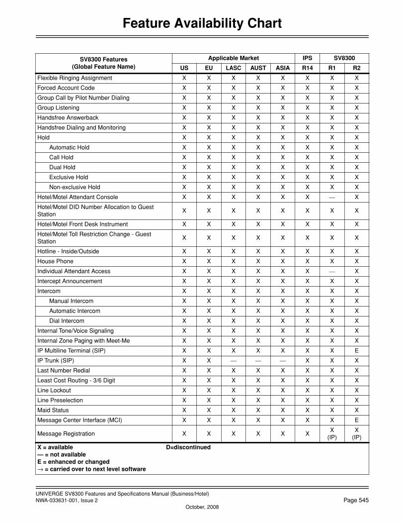
UNIVERGE SV8300 Features and Specifications Manual (Business/Hotel)NWA-033631-001, Issue 2 Page 545
October, 2008
Feature Availability Chart
Flexible Ringing Assignment X X X X X X X X
Forced Account Code X X X X X X X X
Group Call by Pilot Number Dialing X X X X X X X X
Group Listening X X X X X X X X
Handsfree Answerback X X X X X X X X
Handsfree Dialing and Monitoring X X X X X X X X
Hold X X X X X X X X
Automatic Hold X X X X X X X X
Call Hold X X X X X X X X
Dual Hold X X X X X X X X
Exclusive Hold X X X X X X X X
Non-exclusive Hold X X X X X X X X
Hotel/Motel Attendant Console X X X X X X — X
Hotel/Motel DID Number Allocation to Guest Station
X X X X X X X X
Hotel/Motel Front Desk Instrument X X X X X X X X
Hotel/Motel Toll Restriction Change - Guest Station
X X X X X X X X
Hotline - Inside/Outside X X X X X X X X
House Phone X X X X X X X X
Individual Attendant Access X X X X X X — X
Intercept Announcement X X X X X X X X
Intercom X X X X X X X X
Manual Intercom X X X X X X X X
Automatic Intercom X X X X X X X X
Dial Intercom X X X X X X X X
Internal Tone/Voice Signaling X X X X X X X X
Internal Zone Paging with Meet-Me X X X X X X X X
IP Multiline Terminal (SIP) X X X X X X X E
IP Trunk (SIP) X X — — — X X X
Last Number Redial X X X X X X X X
Least Cost Routing - 3/6 Digit X X X X X X X X
Line Lockout X X X X X X X X
Line Preselection X X X X X X X X
Maid Status X X X X X X X X
Message Center Interface (MCI) X X X X X X X E
Message Registration X X X X X XX
(IP)X
(IP)
SV8300 Features(Global Feature Name)
Applicable Market IPS SV8300
US EU LASC AUST ASIA R14 R1 R2
X = available D=discontinued— = not availableE = enhanced or changed→ = carried over to next level software
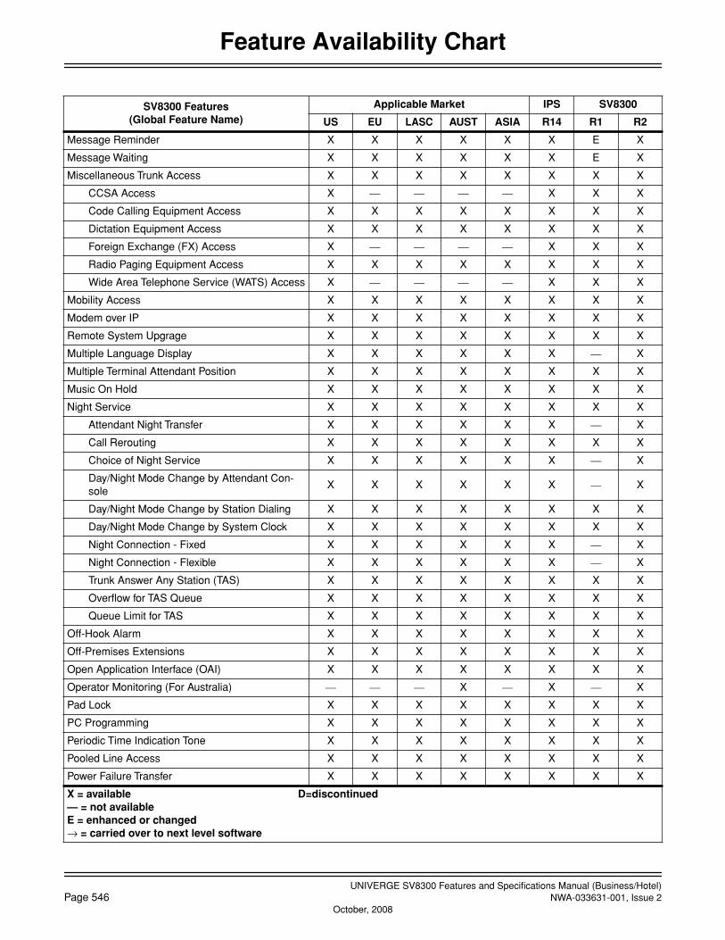
UNIVERGE SV8300 Features and Specifications Manual (Business/Hotel)Page 546 NWA-033631-001, Issue 2
October, 2008
Feature Availability Chart
Message Reminder X X X X X X E X
Message Waiting X X X X X X E X
Miscellaneous Trunk Access X X X X X X X X
CCSA Access X — — — — X X X
Code Calling Equipment Access X X X X X X X X
Dictation Equipment Access X X X X X X X X
Foreign Exchange (FX) Access X — — — — X X X
Radio Paging Equipment Access X X X X X X X X
Wide Area Telephone Service (WATS) Access X — — — — X X X
Mobility Access X X X X X X X X
Modem over IP X X X X X X X X
Remote System Upgrage X X X X X X X X
Multiple Language Display X X X X X X — X
Multiple Terminal Attendant Position X X X X X X X X
Music On Hold X X X X X X X X
Night Service X X X X X X X X
Attendant Night Transfer X X X X X X — X
Call Rerouting X X X X X X X X
Choice of Night Service X X X X X X — X
Day/Night Mode Change by Attendant Con-sole
X X X X X X — X
Day/Night Mode Change by Station Dialing X X X X X X X X
Day/Night Mode Change by System Clock X X X X X X X X
Night Connection - Fixed X X X X X X — X
Night Connection - Flexible X X X X X X — X
Trunk Answer Any Station (TAS) X X X X X X X X
Overflow for TAS Queue X X X X X X X X
Queue Limit for TAS X X X X X X X X
Off-Hook Alarm X X X X X X X X
Off-Premises Extensions X X X X X X X X
Open Application Interface (OAI) X X X X X X X X
Operator Monitoring (For Australia) — — — X — X — X
Pad Lock X X X X X X X X
PC Programming X X X X X X X X
Periodic Time Indication Tone X X X X X X X X
Pooled Line Access X X X X X X X X
Power Failure Transfer X X X X X X X X
SV8300 Features(Global Feature Name)
Applicable Market IPS SV8300
US EU LASC AUST ASIA R14 R1 R2
X = available D=discontinued— = not availableE = enhanced or changed→ = carried over to next level software
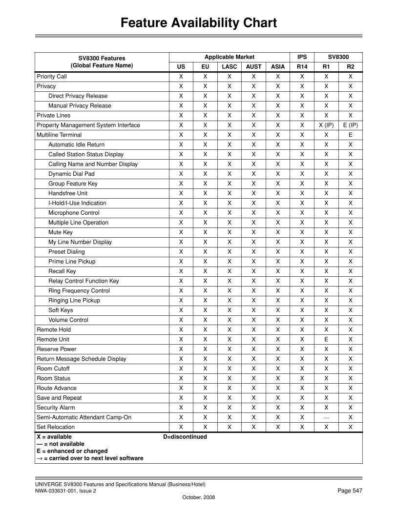
UNIVERGE SV8300 Features and Specifications Manual (Business/Hotel)NWA-033631-001, Issue 2 Page 547
October, 2008
Feature Availability Chart
Priority Call X X X X X X X X
Privacy X X X X X X X X
Direct Privacy Release X X X X X X X X
Manual Privacy Release X X X X X X X X
Private Lines X X X X X X X X
Property Management System Interface X X X X X X X (IP) E (IP)
Multiline Terminal X X X X X X X E
Automatic Idle Return X X X X X X X X
Called Station Status Display X X X X X X X X
Calling Name and Number Display X X X X X X X X
Dynamic Dial Pad X X X X X X X X
Group Feature Key X X X X X X X X
Handsfree Unit X X X X X X X X
I-Hold/I-Use Indication X X X X X X X X
Microphone Control X X X X X X X X
Multiple Line Operation X X X X X X X X
Mute Key X X X X X X X X
My Line Number Display X X X X X X X X
Preset Dialing X X X X X X X X
Prime Line Pickup X X X X X X X X
Recall Key X X X X X X X X
Relay Control Function Key X X X X X X X X
Ring Frequency Control X X X X X X X X
Ringing Line Pickup X X X X X X X X
Soft Keys X X X X X X X X
Volume Control X X X X X X X X
Remote Hold X X X X X X X X
Remote Unit X X X X X X E X
Reserve Power X X X X X X X X
Return Message Schedule Display X X X X X X X X
Room Cutoff X X X X X X X X
Room Status X X X X X X X X
Route Advance X X X X X X X X
Save and Repeat X X X X X X X X
Security Alarm X X X X X X X X
Semi-Automatic Attendant Camp-On X X X X X X — X
Set Relocation X X X X X X X X
SV8300 Features(Global Feature Name)
Applicable Market IPS SV8300
US EU LASC AUST ASIA R14 R1 R2
X = available D=discontinued— = not availableE = enhanced or changed→ = carried over to next level software

UNIVERGE SV8300 Features and Specifications Manual (Business/Hotel)Page 548 NWA-033631-001, Issue 2
October, 2008
Feature Availability Chart
Short Message Service (SMS) — X — — — X X X
Single Digit Dialing X X X X X X X X
Single Digit Feature Access Code X X X X X X X X
SNMP X X X X X X X X
Software Line Appearance (Virtual Extensions) X X X X X X X X
Station Hunting X X X X X X X X
Station Hunting - Circular X X X X X X X X
Station Hunting - Terminal X X X X X X X X
Station Hunting - Secretarial X X X X X X X X
Station Message Detail Recording (SMDR) X X X X X X X X
Station Service Status Display X X X X X X X X
Station Speed Dialing X X X X X X X X
Step Call X X X X X X X X
Supervisory Control of Peripheral Equipment X X X X X X X X
System Clock Setup by Station Dialing X X X X X X X X
System Speed Dialing X X X X X X X X
Tenant Service X X X X X X X X
Tie Lines X X X X X X X X
Tie Line Tandem Switching X X X X X X X X
Timed Forced Release X X X X X X X X
Timed Queue X X X X X X X X
Timed Reminder X X X X X X X X
Trunk - Direct Appearances X X X X X X X X
Trunk Queuing - Outgoing X X X X X X X X
Trunk-to-Trunk Connection X X X X X X X X
Uniform Call Distribution (UCD) X X X X X X X X
Busy In/Busy Out - UCD X X X X X X X X
Call Waiting Indication - UCD X X X X X X X X
Delay Announcement - UCD X X X X X X X X
Hunt Past No Answer - UCD X X X X X X X X
Immediate Overflow - UCD X X X X X X X X
Priority Queuing - UCD X X X X X X X X
Queue Size Control - UCD X X X X X X X X
Silent Monitor - UCD X X X X X X X X
UMS8000 Mail X X X X X — X X
Voice Mail Live Record X X X X X X X X
Voice Mail Private Password X X — — — X X X
SV8300 Features(Global Feature Name)
Applicable Market IPS SV8300
US EU LASC AUST ASIA R14 R1 R2
X = available D=discontinued— = not availableE = enhanced or changed→ = carried over to next level software
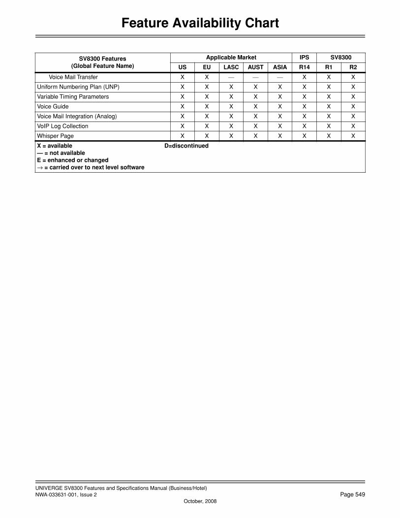
UNIVERGE SV8300 Features and Specifications Manual (Business/Hotel)NWA-033631-001, Issue 2 Page 549
October, 2008
Feature Availability Chart
Voice Mail Transfer X X — — — X X X
Uniform Numbering Plan (UNP) X X X X X X X X
Variable Timing Parameters X X X X X X X X
Voice Guide X X X X X X X X
Voice Mail Integration (Analog) X X X X X X X X
VoIP Log Collection X X X X X X X X
Whisper Page X X X X X X X X
SV8300 Features(Global Feature Name)
Applicable Market IPS SV8300
US EU LASC AUST ASIA R14 R1 R2
X = available D=discontinued— = not availableE = enhanced or changed→ = carried over to next level software

UNIVERGE SV8300 Features and Specifications Manual (Business/Hotel)Page 550 NWA-033631-001, Issue 2