features and benefits - wolf automation · z high level of detail and information regarding applied...
TRANSCRIPT

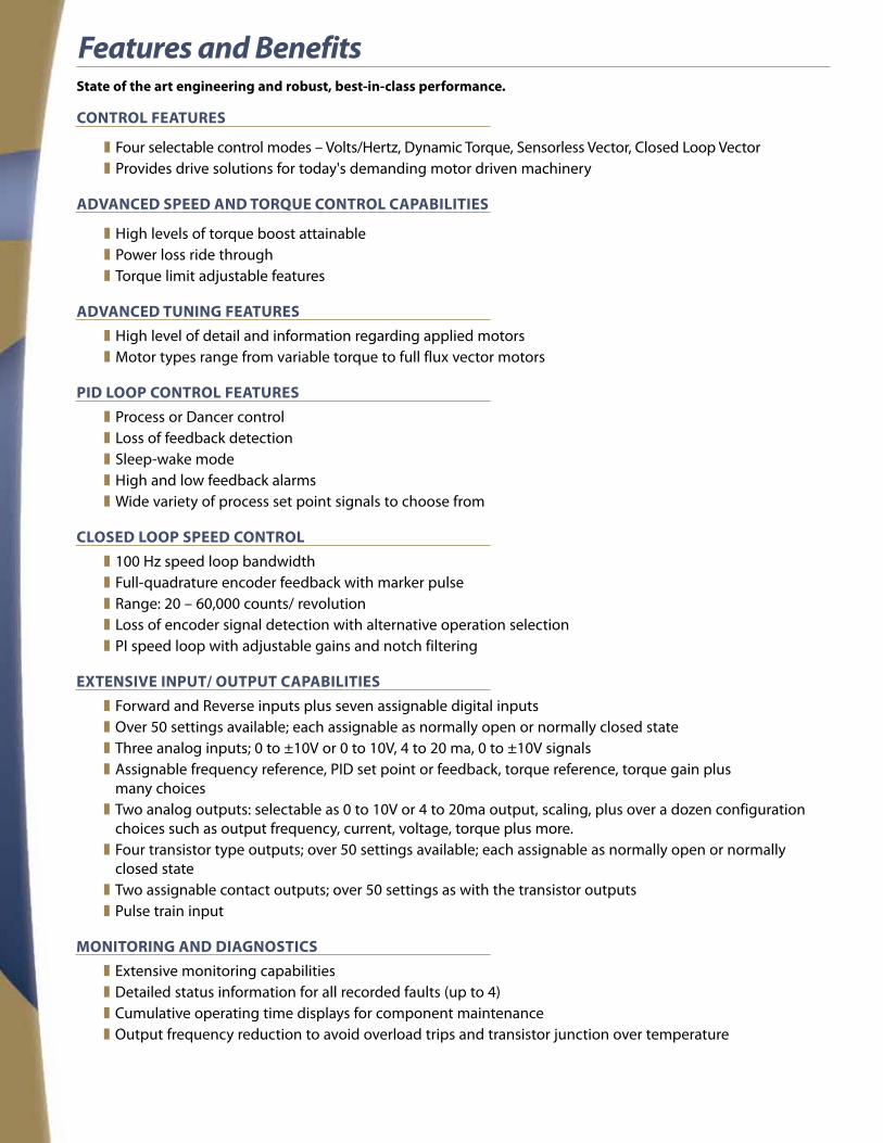
Features and BenefitsState of the art engineering and robust, best-in-class performance.
CONTROL FEATURES
z Four selectable control modes – Volts/Hertz, Dynamic Torque, Sensorless Vector, Closed Loop Vector z Provides drive solutions for today's demanding motor driven machinery
ADVANCED SPEED AND TORQUE CONTROL CAPABILITIES
z High levels of torque boost attainable z Power loss ride through z Torque limit adjustable features
ADVANCED TUNINg FEATURES z High level of detail and information regarding applied motors z Motor types range from variable torque to full flux vector motors
PID LOOP CONTROL FEATURES z Process or Dancer control z Loss of feedback detection z Sleep-wake mode z High and low feedback alarms z Wide variety of process set point signals to choose from
CLOSED LOOP SPEED CONTROL z 100 Hz speed loop bandwidth z Full-quadrature encoder feedback with marker pulse z Range: 20 – 60,000 counts/ revolution z Loss of encoder signal detection with alternative operation selection z PI speed loop with adjustable gains and notch filtering
EXTENSIVE INPUT/ OUTPUT CAPABILITIES z Forward and Reverse inputs plus seven assignable digital inputs z Over 50 settings available; each assignable as normally open or normally closed state z Three analog inputs; 0 to ±10V or 0 to 10V, 4 to 20 ma, 0 to ±10V signals z Assignable frequency reference, PID set point or feedback, torque reference, torque gain plus many choices z Two analog outputs: selectable as 0 to 10V or 4 to 20ma output, scaling, plus over a dozen configuration choices such as output frequency, current, voltage, torque plus more. z Four transistor type outputs; over 50 settings available; each assignable as normally open or normally closed state z Two assignable contact outputs; over 50 settings as with the transistor outputs z Pulse train input
MONITORINg AND DIAgNOSTICS z Extensive monitoring capabilities z Detailed status information for all recorded faults (up to 4) z Cumulative operating time displays for component maintenance z Output frequency reduction to avoid overload trips and transistor junction over temperature
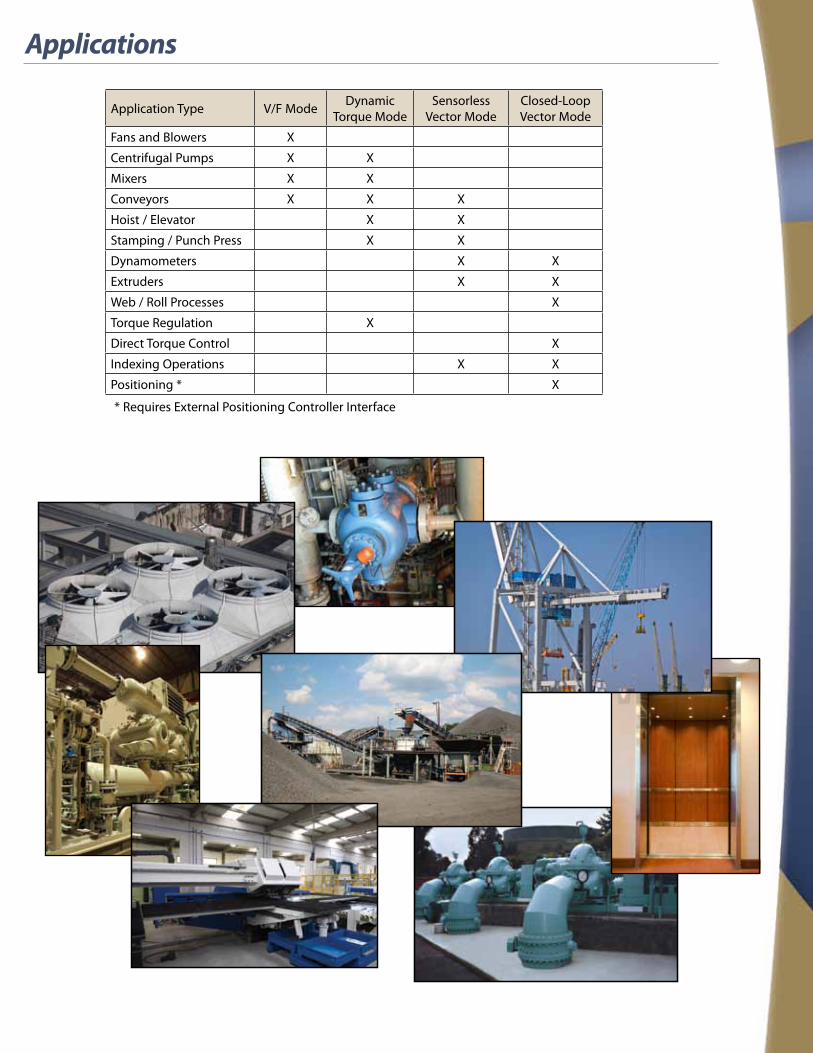
Applications
Application Type V/F Mode Dynamic Torque Mode
Sensorless Vector Mode
Closed-Loop Vector Mode
Fans and Blowers X
Centrifugal Pumps X X
Mixers X X
Conveyors X X X
Hoist / Elevator X X
Stamping / Punch Press X X
Dynamometers X X
Extruders X X
Web / Roll Processes X
Torque Regulation X
Direct Torque Control X
Indexing Operations X X
Positioning * X
* Requires External Positioning Controller Interface

Keypad Panel Functions and Operations
FEATURES:• LED and LCD display for
user-friendly monitoring• Extensive monitoring
and diagnostics• Configuration menus including
a Quick-start menu• Stores configuration settings
for easy download
Type Item Description (information, condition, status)
Unit of Number
Displayed on LED Monitor
Hz Output frequency, frequency command
A Output current
V Output voltage
% Calculated torque, load factor, speed
r/min Motor speed, set motor speed, load shaft speed, set load shaft speed
m/min Line speed, set line speed
kW Input power, motor output
X10 Data greater than 99,999
min Constant feeding rate time, constant feeding rate time setting
sec Timer
PID PID process value
Operating Status
FWD Running (forward rotation)
REV Running (reverse rotation)
STOP No output frequency
Source of Operation
REM Remote mode
LOC Local mode
COMM Communication enabled (RS-485 (standard,optional) field bus option)
JOG Jogging mode
HAND Keypad effective (lights also in local mode)
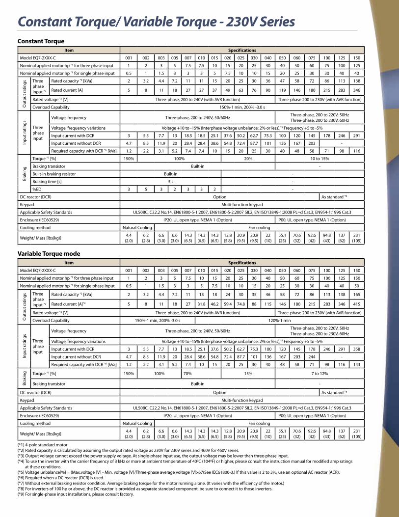
Constant Torque/ Variable Torque - 230V SeriesConstant Torque
Item Specifications
Model EQ7-2XXX-C 001 002 003 005 007 010 015 020 025 030 040 050 060 075 100 125 150
Nominal applied motor hp *1 for three phase input 1 2 3 5 7.5 7.5 10 15 20 25 30 40 50 60 75 100 125
Nominal applied motor hp *1 for single phase input 0.5 1 1.5 3 3 3 5 7.5 10 10 15 20 25 30 30 40 40
Out
put r
atin
gs Three phase input *9
Rated capacity *2 [kVa] 2 3.2 4.4 7.2 11 11 15 20 25 30 36 47 58 72 86 113 138
Rated current [A] 5 8 11 18 27 27 37 49 63 76 90 119 146 180 215 283 346
Rated voltage *3 [V] Three-phase, 200 to 240V (with AVR function) Three-phase 200 to 230V (with AVR function)
Overload Capability 150%-1 min, 200% -3.0 s
Inpu
t rat
ings
Three phase input
Voltage, frequency Three-phase, 200 to 240V, 50/60Hz Three-phase, 200 to 220V, 50Hz Three-phase, 200 to 230V, 60Hz
Voltage, frequency variations Voltage +10 to -15% (Interphase voltage unbalance: 2% or less),*5 Frequency +5 to -5%
Input current with DCR 3 5.5 7.7 13 18.5 18.5 25.1 37.6 50.2 62.7 75.3 100 120 145 178 246 291
Input current without DCR 4.7 8.5 11.9 20 28.4 28.4 38.6 54.8 72.4 87.7 101 136 167 203 -
Required capacity with DCR *6 [kVa] 1.2 2.2 3.1 5.2 7.4 7.4 10 15 20 25 30 40 48 58 71 98 116
Brak
ing
Torque *7 [%] 150% 100% 20% 10 to 15%
Braking transistor Built-in -
Built-in braking resistor Built-in -
Braking time [s] 5 s -
%ED 3 5 3 2 3 3 2 -
DC reactor (DCR) Option As standard *8
Keypad Multi-function keypad
Applicable Safety Standards UL508C, C22.2 No.14, EN61800-5-1:2007, EN61800-5-2:2007 SIL2, EN ISO13849-1:2008 PL=d Cat.3, EN954-1:1996 Cat.3
Enclosure (IEC60529) IP20, UL open type, NEMA 1 (Option) IP00, UL open type, NEMA 1 (Option)
Cooling method Natural Cooling Fan cooling
Weight/ Mass [lbs(kg)] 4.4 (2.0)
6.2 (2.8)
6.6 (3.0)
6.6 (3.0)
14.3 (6.5)
14.3 (6.5)
14.3 (6.5)
12.8 (5.8)
20.9 (9.5)
20.9 (9.5)
22 (10)
55.1 (25)
70.6 (32)
92.6 (42)
94.8 (43)
137 (62)
231 (105)
Variable Torque modeItem Specifications
Model EQ7-2XXX-C 001 002 003 005 007 010 015 020 025 030 040 050 060 075 100 125 150
Nominal applied motor hp *1 for three phase input 1 2 3 5 7.5 10 15 20 25 30 40 50 60 75 100 125 150
Nominal applied motor hp *1 for single phase input 0.5 1 1.5 3 3 5 7.5 10 10 15 20 25 30 30 40 40 50
Out
put r
atin
gs Three phase input *9
Rated capacity *2 [kVa] 2 3.2 4.4 7.2 11 13 18 24 30 35 46 58 72 86 113 138 165
Rated current [A]*4 5 8 11 18 27 31.8 46.2 59.4 74.8 88 115 146 180 215 283 346 415
Rated voltage *3 [V] Three-phase, 200 to 240V (with AVR function) Three-phase 200 to 230V (with AVR function)
Overload Capability 150%-1 min, 200% -3.0 s 120%-1 min
Inpu
t rat
ings
Three phase input
Voltage, frequency Three-phase, 200 to 240V, 50/60Hz Three-phase, 200 to 220V, 50Hz Three-phase, 200 to 230V, 60Hz
Voltage, frequency variations Voltage +10 to -15% (Interphase voltage unbalance: 2% or less),*5 Frequency +5 to -5%
Input current with DCR 3 5.5 7.7 13 18.5 25.1 37.6 50.2 62.7 75.3 100 120 145 178 246 291 358
Input current without DCR 4.7 8.5 11.9 20 28.4 38.6 54.8 72.4 87.7 101 136 167 203 244 -
Required capacity with DCR *6 [kVa] 1.2 2.2 3.1 5.2 7.4 10 15 20 25 30 40 48 58 71 98 116 143
Brak
ing Torque *7 [%] 150% 100% 70% 15% 7 to 12%
Braking transistor Built-in -
DC reactor (DCR) Option As standard *8
Keypad Multi-function keypad
Applicable Safety Standards UL508C, C22.2 No.14, EN61800-5-1:2007, EN61800-5-2:2007 SIL2, EN ISO13849-1:2008 PL=d Cat.3, EN954-1:1996 Cat.3
Enclosure (IEC60529) IP20, UL open type, NEMA 1 (Option) IP00, UL open type, NEMA 1 (Option)
Cooling method Natural Cooling Fan cooling
Weight/ Mass [lbs(kg)] 4.4 (2.0)
6.2 (2.8)
6.6 (3.0)
6.6 (3.0)
14.3 (6.5)
14.3 (6.5)
14.3 (6.5)
12.8 (5.8)
20.9 (9.5)
20.9 (9.5)
22 (10)
55.1 (25)
70.6 (32)
92.6 (42)
94.8 (43)
137 (62)
231 (105)
(*1) 4-pole standard motor(*2) Rated capacity is calculated by assuming the output rated voltage as 230V for 230V series and 460V for 460V series.(*3) Output voltage cannot exceed the power supply voltage. At single-phase input use, the output voltage may be lower than three-phase input.(*4) To use the inverter with the carrier frequency of 3 kHz or more at ambient temperature of 400C (1040F) or higher, please consult the instruction manual for modified amp ratings at these conditions(*5) Voltage unbalance[%] = (Max.voltage [V] - Min. voltage [V]/Three-phase average voltage [V]x67(See IEC61800-3.) If this value is 2 to 3%, use an optional AC reactor (ACR).(*6) Required when a DC reactor (DCR) is used.(*7) Without external braking resistor condition. Average braking torque for the motor running alone. (It varies with the efficiency of the motor.)(*8) For inverters of 100 hp or above, the DC reactor is provided as separate standard component. be sure to connect it to those inverters.(*9) For single-phase input installations, please consult factory.
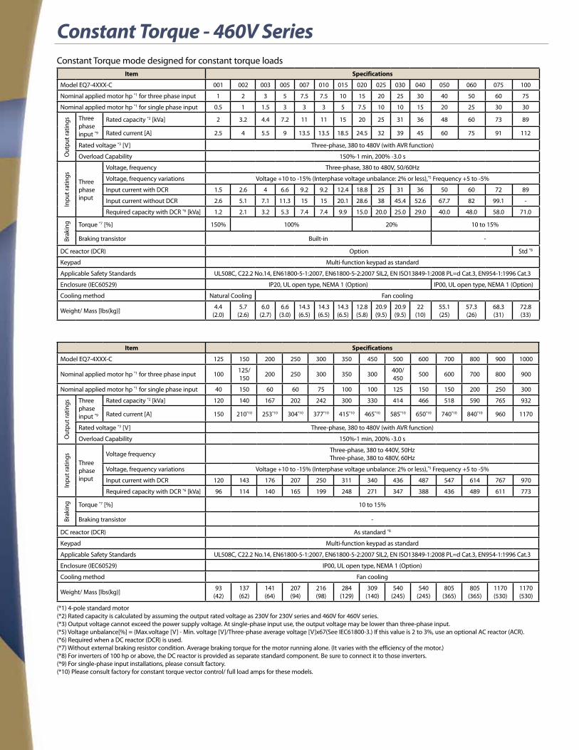
Constant Torque - 460V SeriesConstant Torque mode designed for constant torque loads
Item Specifications
Model EQ7-4XXX-C 001 002 003 005 007 010 015 020 025 030 040 050 060 075 100
Nominal applied motor hp *1 for three phase input 1 2 3 5 7.5 7.5 10 15 20 25 30 40 50 60 75
Nominal applied motor hp *1 for single phase input 0.5 1 1.5 3 3 3 5 7.5 10 10 15 20 25 30 30
Out
put r
atin
gs Three phase input *9
Rated capacity *2 [kVa] 2 3.2 4.4 7.2 11 11 15 20 25 31 36 48 60 73 89
Rated current [A] 2.5 4 5.5 9 13.5 13.5 18.5 24.5 32 39 45 60 75 91 112
Rated voltage *3 [V] Three-phase, 380 to 480V (with AVR function)
Overload Capability 150%-1 min, 200% -3.0 s
Inpu
t rat
ings
Three phase input
Voltage, frequency Three-phase, 380 to 480V, 50/60Hz
Voltage, frequency variations Voltage +10 to -15% (Interphase voltage unbalance: 2% or less),*5 Frequency +5 to -5%
Input current with DCR 1.5 2.6 4 6.6 9.2 9.2 12.4 18.8 25 31 36 50 60 72 89
Input current without DCR 2.6 5.1 7.1 11.3 15 15 20.1 28.6 38 45.4 52.6 67.7 82 99.1 -
Required capacity with DCR *6 [kVa] 1.2 2.1 3.2 5.3 7.4 7.4 9.9 15.0 20.0 25.0 29.0 40.0 48.0 58.0 71.0
Brak
ing Torque *7 [%] 150% 100% 20% 10 to 15%
Braking transistor Built-in -
DC reactor (DCR) Option Std *8
Keypad Multi-function keypad as standard
Applicable Safety Standards UL508C, C22.2 No.14, EN61800-5-1:2007, EN61800-5-2:2007 SIL2, EN ISO13849-1:2008 PL=d Cat.3, EN954-1:1996 Cat.3
Enclosure (IEC60529) IP20, UL open type, NEMA 1 (Option) IP00, UL open type, NEMA 1 (Option)
Cooling method Natural Cooling Fan cooling
Weight/ Mass [lbs(kg)] 4.4 (2.0)
5.7 (2.6)
6.0 (2.7)
6.6 (3.0)
14.3 (6.5)
14.3 (6.5)
14.3 (6.5)
12.8 (5.8)
20.9 (9.5)
20.9 (9.5)
22 (10)
55.1 (25)
57.3 (26)
68.3 (31)
72.8 (33)
Item Specifications
Model EQ7-4XXX-C 125 150 200 250 300 350 450 500 600 700 800 900 1000
Nominal applied motor hp *1 for three phase input 100 125/ 150 200 250 300 350 300 400/
450 500 600 700 800 900
Nominal applied motor hp *1 for single phase input 40 150 60 60 75 100 100 125 150 150 200 250 300
Out
put r
atin
gs Three phase input *9
Rated capacity *2 [kVa] 120 140 167 202 242 300 330 414 466 518 590 765 932
Rated current [A] 150 210*10 253*10 304*10 377*10 415*10 465*10 585*10 650*10 740*10 840*10 960 1170
Rated voltage *3 [V] Three-phase, 380 to 480V (with AVR function)
Overload Capability 150%-1 min, 200% -3.0 s
Inpu
t rat
ings
Three phase input
Voltage frequency Three-phase, 380 to 440V, 50Hz Three-phase, 380 to 480V, 60Hz
Voltage, frequency variations Voltage +10 to -15% (Interphase voltage unbalance: 2% or less),*5 Frequency +5 to -5%
Input current with DCR 120 143 176 207 250 311 340 436 487 547 614 767 970
Required capacity with DCR *6 [kVa] 96 114 140 165 199 248 271 347 388 436 489 611 773
Brak
ing Torque *7 [%] 10 to 15%
Braking transistor -
DC reactor (DCR) As standard *8
Keypad Multi-function keypad as standard
Applicable Safety Standards UL508C, C22.2 No.14, EN61800-5-1:2007, EN61800-5-2:2007 SIL2, EN ISO13849-1:2008 PL=d Cat.3, EN954-1:1996 Cat.3
Enclosure (IEC60529) IP00, UL open type, NEMA 1 (Option)
Cooling method Fan cooling
Weight/ Mass [lbs(kg)] 93 (42)
137 (62)
141 (64)
207 (94)
216 (98)
284 (129)
309 (140)
540 (245)
540 (245)
805 (365)
805 (365)
1170 (530)
1170 (530)
(*1) 4-pole standard motor(*2) Rated capacity is calculated by assuming the output rated voltage as 230V for 230V series and 460V for 460V series.(*3) Output voltage cannot exceed the power supply voltage. At single-phase input use, the output voltage may be lower than three-phase input.(*5) Voltage unbalance[%] = (Max.voltage [V] - Min. voltage [V]/Three-phase average voltage [V]x67(See IEC61800-3.) If this value is 2 to 3%, use an optional AC reactor (ACR).(*6) Required when a DC reactor (DCR) is used.(*7) Without external braking resistor condition. Average braking torque for the motor running alone. (It varies with the efficiency of the motor.)(*8) For inverters of 100 hp or above, the DC reactor is provided as separate standard component. Be sure to connect it to those inverters.(*9) For single-phase input installations, please consult factory.(*10) Please consult factory for constant torque vector control/ full load amps for these models.

Variable Torque - 460V SeriesVariable Torque mode designed for variable torque load applications
Item Specifications
Model EQ7-4XXX-C 001 002 003 005 007 010 015 020 025 030 040 050 060 075 100
Nominal applied motor hp *1 for three phase input 1 2 3 5 7.5 10 15 20 25 30 40 50 60 75 100
Nominal applied motor hp *1 for single phase input 0.5 1 1.5 3 3 5 7.5 10 10 15 20 25 30 30 40
Out
put r
atin
gs Three phase input *9
Rated capacity *2 [kVa] 2 3.2 4.4 7.2 11 13.1 18.3 24 29 36 48 60 73 89 120
Rated current [A] 2.5 4 5.5 9 13.5 16.5 23 30.5 37 45 60 75 91 112 150
Rated voltage *3 [V] Three-phase, 380 to 480V (with AVR function)
Overload Capability 150%-1 min, 200% -3.0 s 120%-1 min
Inpu
t rat
ings
Three phase input
Voltage, frequency Three-phase, 380 to 480V, 50/60Hz
Voltage, frequency variations Voltage +10 to -15% (Interphase voltage unbalance: 2% or less),*5 Frequency +5 to -5%
Input current with DCR 1.5 2.6 4 6.6 9.2 12.5 18.8 25.1 31.3 36.3 50.2 60.2 72.7 89.1 120
Input current without DCR 2.6 5.1 7.1 11.3 15 20.1 28.6 35 45.4 52.6 67.7 82 99.1 121 -
Required capacity with DCR *6 [kVa] 1.2 2.2 3.1 5.2 7.4 10 15 20 25 29 40 48 58 71 96
Brak
ing Torque *7 [%] 150% 100% 70% 15 7 to 12%
Braking transistor Built-in -
DC reactor (DCR) Option Std *8
Keypad Multi-function keypad as standard
Applicable Safety Standards UL508C, C22.2 No.14, EN61800-5-1:2007, EN61800-5-2:2007 SIL2, EN ISO13849-1:2008 PL=d Cat.3, EN954-1:1996 Cat.3
Enclosure (IEC60529) IP20, UL open type, NEMA 1 (Option) IP00, UL open type, NEMA 1 (Option)
Cooling method Natural Cooling Fan cooling
Weight/ Mass [lbs(kg)] 4.4 (2.0)
5.7 (2.6)
6.0 (2.7)
6.6 (3.0)
14.3 (6.5)
14.3 (6.5)
14.3 (6.5)
12.8 (5.8)
20.9 (9.5)
20.9 (9.5)
22 (10)
55.1 (25)
57.3 (26)
68.3 (31)
72.8 (33)
Item Specifications
Model EQ7-4XXX-C 125 150 200 250 300 350 450 500 600 700 800 900 1000
Nominal applied motor hp *1 for three phase input 125 150 200 250 300 350 450 500 600 700 800 900 1000
Nominal applied motor hp *1 for single phase input 50 50 60 75 100 100 125 150 200 200 250 300 400
Out
put r
atin
gs Three phase input *9
Rated capacity *2 [kVa] 140 167 202 242 300 331 414 518 590 669 765 932 1092
Rated current [A] 176 210 253 304 377 415 520 650 740 840 960 1170 1370
Rated voltage *3 [V] Three-phase, 380 to 480V (with AVR function)
Overload Capability 120%-1 min
Inpu
t rat
ings
Three phase input
Voltage frequency Three-phase, 380 to 440V, 50Hz Three-phase, 380 to 480V, 60Hz
Voltage, frequency variations Voltage +10 to -15% (Interphase voltage unbalance: 2% or less),*5 Frequency +5 to -5%
Input current with DCR 143 175 207 249 311 340 435 547 613 686 766 970 1093
Required capacity with DCR *6 [kVa] 114 140 165 199 248 271 347 436 489 547 611 773 871
Brak
ing Torque *7 [%] 7 to 12%
Braking transistor -
DC reactor (DCR) As standard *8
Keypad Multi-function keypad as standard
Applicable Safety Standards UL508C, C22.2 No.14, EN61800-5-1:2007, EN61800-5-2:2007 SIL2, EN ISO13849-1:2008 PL=d Cat.3, EN954-1:1996 Cat.3
Enclosure (IEC60529) IP00, UL open type, NEMA 1 (Option)
Cooling method Fan cooling
Weight/ Mass [lbs(kg)] 93 (42)
137 (62)
141 (64)
207 (94)
216 (98)
284 (129)
309 (140)
540 (245)
540 (245)
805 (365)
805 (365)
1170 (530)
1170 (530)
(*1) 4-pole standard motor(*2) Rated capacity is calculated by assuming the output rated voltage as 230V for 230V series and 460V for 460V series.(*3) Output voltage cannot exceed the power supply voltage. At single-phase input use, the output voltage may be lower than three-phase input.(*5) Voltage unbalance[%] = (Max.voltage [V] - Min. voltage [V]/Three-phase average voltage [V]x67(See IEC61800-3.) If this value is 2 to 3%, use an optional AC reactor (ACR).(*6) Required when a DC reactor (DCR) is used.(*7) Without external braking resistor condition. Average braking torque for the motor running alone. (It varies with the efficiency of the motor.)(*8) For inverters of 100 hp or above, the DC reactor is provided as separate standard component. Be sure to connect it to those inverters.(*9) For single-phase input installations, please consult factory.

Common SpecificationsVariable Torque mode designed for variable torque load applications
Item Specifications
Out
put
Sett
ing
rang
e
Maximum frequency500 Hz (Constant Torque and dynamic torque modes)200 Hz (CT Vector and PG Feedback)120 Hz (CT-Variable Torque and sensorless vector mode)
Base frequency 25 to 500 Hz variable setting (Variable Torque (Model EQ7-x0P5-C or above) and Constant Torque mode: 120 Hz)
Starting Frequency 0.1 to 60.0 Hz variable setting (sensorless vector control*6/ vector control w/PG, 0.0Hz for*7)
Carrier frequency
• 0.75 to 16 kHz (Constant Torque: EQ7-x001-C to EQ7-x100-C, Variable Torque: EQ7-x001-C to EQ7-x040-C)
• 0.75 to 10 kHz (CT-Vector: EQ7-x125-C to EQ7-x800-C, Variable Torque: EQ7-x050-C to EQ7-x100-C)
• 0.75 to 2 kHz (Constant Torque V/F: EQ7-x150-C to EQ7-x800-C)
• 0.75 to 6 kHz (CT-Vector: EQ7-x900-C to EQ7-x1000-C, Variable Torque: EQ7-x125-C to EQ7-x900-C)
• 0.75 to 4 kHz (Variable Torque: EQ7-x1000-C)
NOTE: Frequency drops automatically to protect the inverter depending on environmental temperature and output current.(This auto drop function can be cancelled)
Output frequency accuracy (Stability)• Analog setting: ±0.2% of max. frequency (at 25 ±10°C)*1
• Digital setting: ±0.01% of max. frequency (at -10 to +50°C)
Setting resolution
• Analog setting: Analog setting: 1/3000 of max. frequency (1/1500 with V2 input)
• Keypad setting: 0.01Hz (99.99Hz or less), 0.1Hz (100.0 to 500Hz)
• Link setting: 1/20000 of max. frequency or 0.01 Hz (fixed)
Speed control range• Min. speed: Base speed 1:1500 (4P 1r/min to 1500r/min)*7
• Min speed: Base speed 1:200 (4P 7.5r/min to 1500r/min)
Spee
d co
ntro
l ac
cura
cy
Vector control with speed sensor• Analog setting: ±0.2% of max. frequency (at 25 ±10°C)
• Digital setting: ±0.01% of max. frequency (at -10 to +50°C)
Vector control without speed sensor
• Analog setting: ±0.5% or below of base speed (at 25 ±10°C)
• Digital setting: ±0.5% or below of base speed (at -10 to +50°C)
Cont
rol
Control method
• V/f control
• Dynamic torque control
• Vector control without speed sensor
• Vector control with speed sensor (with an optional PG interface card mounted)
Voltage/freq. characteristics
230V (460V) Series• Base Frequency and max. output frequency can be set to 80 to 240V (160-500V) in common.
• The AVR control ON/OFF can be selected.*1
• Non-linear V/f setting (3 points) free voltage 0 to 240V (0-500V) and frequency (0 to 500Hz) can be set.*1
Torque boost
• Auto torque boost (for constant torque load)*1 to *2
• Manual torque boost: Desired torque boost (0.0 to 20.0%) can be set.*1
• Select application load with function code F37. (Variable torque load or constant torque load)*1
Starting torque (Constant Torque mode)
• EQ7-x040-C or below: 200% or higher, EQ7-x050-C or above: 180% or higher/set frequency: 0.3Hz (Base frequency 50 Hz, slip compensation and auto torque boost operation*1, only *2)
Start/ stop operation
Keypad• Multi-function keypad: Start and stop with FWD, REV, and STOP keys
External signals (digital inputs): Forward (reverse) rotation, stop command (capable of 3-wire operation), coast-to-stop command, external alarm, alarm reset, etc.
Link operation: Operation through RS-485 or field bus (option) communications.
Remote/Local Switching
Acceleration/ deceleration time
• Setting range: From 0.00 to 6000s
• Switch: The four sets of accel/ decel. times can be set or selected individually (switchable during operation).
• Acceleration/deceleration pattern: Linear accel./decel., S-shape accel./decel. (weak, free, strong), curvilinear accel./decel. (accel./decel. max capacity of constant output)
• Deceleration mode (coast-to-stop): Coast-to-stop at the operation command OFF.
• Forcible stop decel. time: Deceleration stop by the forcible stop (STOP)
(*1) Effective function in V/f control(*2) Effective function in dynamic torque control(*6) effective function in vector control without speed sensor(*7) Effective function in vector control with speed sensor (PG option is necessary.)(*8) This specification does not guarantee that all single fault cases are surely detected (EN954-1/EN ISO 13849-1, Cat. 3)

Common Specifications - ContinuedVariable Torque mode designed for variable torque load applications
Item Specifications
Cont
rol
Auto-restart after momentary power failure Adjustable to restart at running speed, trip on power failure, or ride through on load inertia
Current limit by hardware Limiting the current by hardware to prevent overcurrent trip due to sharp load change or momentary power failure which cannot be controlled by software current limit. (This function can be cancelled.) Operation Level (20 to 200%)
Digital Input Forward run, reverse run, plus 7 configurable 24V DC inputs that can be set for over 50 events, both as normally open or closed.
Transistor output Four transistor and two relay outputs configurable to indicate over 50 possible events as both normally open or closed.
Analog output
• Terminals [FM1] and [FM2]
• Output a selected signal with analog DC voltage (0 to +10V) or analog DC current (4 to 20 mA)
• Selectable output to over 15 assigned parameters
Indication: Trip Mode Trip History: Saves and displays the last 4 trip factors and their detailed description.
Oth
er fe
atur
es Communications RS-485 COM port 1 (for keypad connection), RS-485 COM port 2 (on terminal board)
Protection against momentary power failure
Upon detection of a momentary power failure lasting more than 15 ms, this function stops the inverter output. If restart after momentary power failure is selected, this function invokes a restart process if power is restored within a predeter-mined period (allowable momentary power failure time).
Envi
ronm
ent
Installation location Shall be free from corrosive gases, flammable gases, oil mist, dust, direct sunlight. (Pollution degree 2 (IEC60664-1)). Indoor use only.
Ambient temperature Open type: -10 to +50°C (14 to 122°F)
Ambient humidity 5 to 95% RH (without condensation)
Altitude Lower than 3300ft (1000m)
Atmospheric pressure 86 to 106kPa
Storage temperature -25 to +65°C (-13 to 149°F)
Storage humidity 5 to 95% RH (without condensation)
Cont
rol
Enable input (Safe Torque Off (STO)) Opening the circuit between terminals [EN1] and PLC or terminals [EN2] and [PLC] stops the inverter's output transistor (Safe Torque Off: STO)
Frequency setting
• Keypad: can be set with UP and DOWN keys• External Voltage: Can be set with external potentiometer (1 to 5kΩ 1/2W)• Analog input: 0 to ±10 VDC (±5 VDC)/0 to ±100% or 0 to +10VDC (+5VDC)/ 0 to +100% (Terminals [12] and [V2])
(inverse operation via parameter) +4 to +20 mA DC/0 to 100% (or 0 to +20mA) (inverse operation via parameter)
• Up/DOWN operation: Frequency can be increased or decreased while the digital input signal is ON.• Multi-frequency: Selectable from 16 pre-set speeds• Link operation: Frequency can be set through RS-485 (standard setting)• Switching frequency setting: Frequency setting can be switched (2 settings) with external signal (digital input).• Auxiliary frequency setting: Terminal [12], [C1], or [V2] input can be selected respectively as an additional input• Pulse train input: Pulse input = X7 terminal, rotational direction = general terminal
Complementary output: Max. 100kHz, Open collector output: Max. 30kHz• Pulse train input: PG interface option CW/CCW pulse, pulse + rotational direction
Complementary output: Max. 100kHz, Open collector output: Max. 25kHz
PID control
• Terminals [FM1] and [FM2]• Output a selected signal with analog DC voltage (0 to +10V) or analog DC current (4 to 20 mA)• Selectable output to over 15 assigned parameters• PID adjuster for process control and that for dancer control• Switchable between forward and reverse operations• Low liquid level stop function (pressurized operation possible before low liquid level stop)• PID command: Keypad, analog input (from terminals [12], C1 V2), RS-485 communications• PID feedback value: Analog input (from terminals [12], C1, V2)• Alarm output (absolute value alarm, deviation alarm)• PID output limiter• Integratrion reset/hold
Torque limiter• Torque limit value (±300%)• Torque limiter 1/2, torque limiter enabled/disabled, analog torque limit value
Control functions
• Analog input adjustment (gain/offset/filter time constant), frequency limiter (high and low), bias freqency, jump frequency, jogging operation, pre-excitation, switch to commercial power, commercial power switching sequence, cooling fan ON/OFF control, select motor 2 to 4, protect motor from dew condensation, universal DI, universal DO, universal AO, rotational direction limitation
• Overload prevention control, auto search, slip compensation, automatic deceleration (anti-regenerative control), droop control, deceleration characteristics (improving braking capability), auto energy saving function
• Offline tuning• Life early warning, cumulative inverter run time, cumulative motor run time• Light alarm, retry, command loss detection
(*1) Effective function in V/f control(*2) Effective function in dynamic torque vector control(*6) effective function in vector control without speed sensor(*7) Effective function in vector control with speed sensor (PG option is necessary.)(*8) This specification does not guarantee that all single fault cases are surely detected (EN954-1/EN ISO 13849-1, Cat. 3)
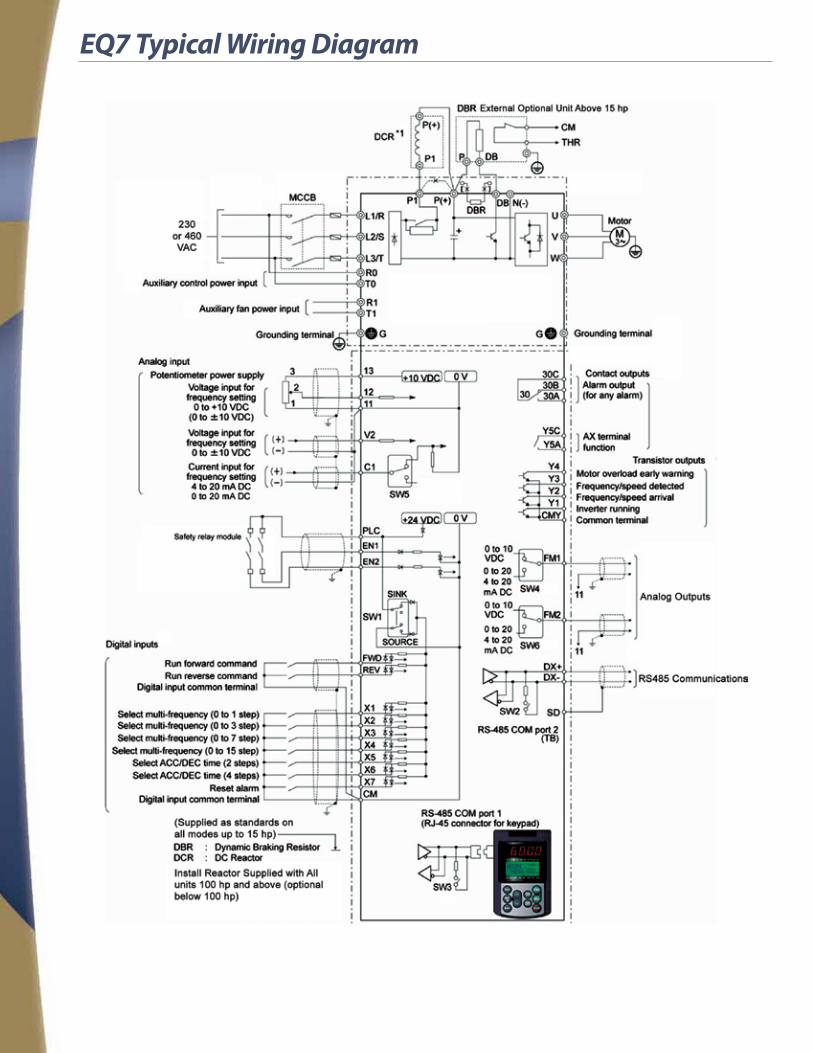
EQ7 Typical Wiring Diagram

Dimensions and Weights
11-12
Inverter type EQ7-2XXX-C-EQ7-4XXX-C
Dimensions inch (mm)
230 V 460 V W W1 W2 H H1 H2 D D1 D2 D3 ØA
4.33 (110)
3.78 (96)
0.24 (6)
10.24 (260)
9.69 (246)
0.28 (7)
4.45 (113)
0.12 (3)
0.24 (6)
001 001
5.71 (145)
1.26 (32)
002 002
5.91 (150)
5.35 (136)
003 003
005 005
007 007
8.66 (220)
7.72 (196)
0.39 (10)
9.37 (238)
0.43 (11)
7.68 (195)
4.13 (105)
3.54 (90)
0.39 (10)
0.39 (10)
010 010 015 015 020 020 025 025
9.84 (250)
8.9 (226)
15.75 (400)
14.88 (378) 030 030
040 040
050 050 12.6
(320) 9.45 (240)
21.65 (550)
20.87 (530)
0.47 (12)
10.04 (255)
4.53 (115)
5.51 (140)
0.16 (4)
060
060 075
13.98 (355)
10.83 (275)
24.21 (615)
23.43 (595)
10.63 (270)
6.1 (155)
- 100 26.57 (675)
25.79 (655)
75 125 29.13
(740) 28.35 (720)
100
125 - 20.87 (530)
16.93 (430)
0.59 (15)
29.53 (750)
0.61 (15.5)
11.22 (285)
5.71 (145)
5.51 (140)
0.59 (15)
150 - 24.8 (630)
11.42 (290)
34.65 (880)
33.46 (850)
14.17 (360)
7.09 (180)
7.09 (180)
- 150
20.87 (530)
16.93 (430)
29.13 (740)
27.95 (710)
12.4 (315)
5.31 (135) - 200
- 250
39.37 (1000)
38.19 (970)
14.17 (360)
7.09 (180)
- 300 - 350
26.77 (680)
11.42 (290)
- 450 - 500
55.12 (1400)
53.94 (1370)
17.32 (440)
10.24 (260) 0.25
(6.4)
- 600 - 700 34.65
(880) 10.24 (260) - 800
- 900 39.37 (1000)
11.81 (300)
61.02 (1550)
59.84 (1520)
19.69 (500)
12.33 (313.2)
7.35 (186.8) - 1000
40 HP or below
50 HP or above

DC Reactor
230 V Standard FigureA
100125150
DCR2-75CDCR2-90CDCR2-110C
25(11.4)
31(14)37
(17)
5.71(145)6.1
(155)7.28(185)
10.04±0.39(255±10)
8.86(225)
10.43(265)
11.81±0.39(300±10)
10.04±0.39(255±10)
11.81±0.39(300±10)
4.17±0.08(106±2)
4.57±0.08(116±2)
4.57±0.16(116±4)
3.39(86)3.78(96)3.54(90)
2.09±0.04(53±1)
2.28±0.04(58±1)
5.71(145)
6.3(160) M8
M6M12
Note: 100 HP or above type comes with a DC reactor (DCR) suitable for the LD-mode use
Note: 100 HP or above type comes with a DC reactor (DCR) suitable for the LD-mode use
460 V Standard
FigureA
FigureB
FigureC
100125150200250300350450500600700800900
1000
DCR4-75CDCR4-90CDCR4-110CDCR4-132CDCR4-160CDCR4-200CDCR4-220CDCR4-280CDCR4-355CDCR4-400CDCR4-450CDCR4-500CDCR4-630CDCR4-710C
27(12.4)
32(14.7)
41(18.4)
49(22)56
(25.5)65
(29.5)72
(32.5)79
(36)104(47)115(52)132(60)154(70)165(75)209(95)
5.71(145)
7.48(190)
9.65(245)
2.09±0.04(53±1)
2.28±0.04(58±1)
2.48±0.08(63±2)
2.58±0.08(65.5±2)
2.78±0.08(70.5±2)
2.87±0.08(73±2)
3.17±0.08(80.5±2)3.07±0.04
(78±1)2.85±0.04(72.5±1)
2.95±0.08(75±2)
3.25±0.08(82.5±2)
4.09±0.08(104±2)
4.21±0.08(107±2)
3.39(86)3.78(96)3.54(90)3.94(100)4.06(103)4.45(113)4.65(118)5.24(133)5.04(128)4.61(117)4.8
(122)5.39(137)6.69(170)10.04(255)
4.17±0.08(106±2)
4.57±0.08(116±2)
4.96±0.16(126±4)
5.16±0.16(131±4)
5.55±0.16(141±4)
5.75±0.16(146±4)
6.34±0.16(161±4)
6.14±0.16(156±4)
5.71±0.16(145±4)
5.91±0.16(150±4)6.5±0.16(165±4)
7.99±0.16(203±4)
11.61±0.16(295±4)
8.86(225)
10.43(265)
12.2(310)
12.2(310)13.58(345)
15.16(385)
15.35(390)5.71(145)6.3
(160)
13.78±0.39(350±10)
13.78±0.39(350±10)
15.75±0.39(400±10)
17.52±0.39(445±10)
17.32±0.39(440±10)
17.52±0.39(445±10)
11.22±0.39(285±10)
13.39±0.39(340±10)
4.92(125)5.51(140)6.89(175)
7.09(180)
7.28(185)7.87(200)8.27(210)7.87(200)8.39(213)8.46(215)8.66(220)7.68(195)8.86(225)
18.9(480)
6.1(155)
7.48(190)
6.3(160)
8.86(225)
M6
M8
M10
M10
M12
M10
M12
M16
Ø15
Powersupplyvoltage
Inverter typeFRN _ _ _ GIS
-2U/4U
Option/Standard
Referto: Mounting
holeTerminal
hole
Masslb (kg)Reactor
W W1 D D1 D2 D3 H
W W1 D D1 D2 D3 H
Dimensions inch (mm)
Powersupplyvoltage
Inverter typeFRN _ _ _ GIS
-2U/4U
Option/Standard
Referto: Mounting
holeTerminal
hole
Masslb (kg)Reactor
Dimensions inch (mm)
46
MA
X. H
WW1
D3 MAX. D2
DD1
4 x Mounting hole
2 x Terminalhole
MA
X. H
WW1
4 x Mounting hole
D3 MAX. D2
DD1
2 x 4 x Terminalhole
MA
X. H
WW1
D3 MAX. D2
DD1
4 x Mounting hole
DCR4-630C : 2 x 4 x Terminal holeDCR4-710C : 2 x 4 x Terminal hole
C erugiFB erugiFFigure A
DC Link Reactors provide smoothing capabilitiesto the DC bus sections in EQ7 Drives.
All units 100 hp and above come with a separateDC Link Reactor ready for �eld wiring at theDC Bus terminals
PowerSupplyVoltage
Inverter TypeFRN _ _ _ GIS
-2U/4U
Option/Standard Reactor Refer to:
Dimensions in Inches (mm)Mass
lb (kg)W W1 D D1 D2 D3 H Mounting Hole
Terminal Hole
230 V
100
Standard
DCR2-75C
Figure A
10.04±0.39 (255±10)
8.86 (225)
4.17±0.08 (106±2)
3.39 (86)
5.71 (145)
2.09±0.04 (53±1) 5.71
(145) M6
M12
25 (11.4)
125 DCR2-90C 4.57±0.08 (116±2)
3.78 (96)
6.1 (155) 2.28±0.04
(58±1)
31 (14)
150 DCR2-110C 11.81±0.39 (300±10)
10.43 (265)
4.57±0.16 (116±4)
3.54 (90)
7.28 (185)
6.3 (160) M8 37
(17)
Note: 100 hp or above type comes with a CD reactor (DCR) suitable for the LD-mode use
Power Supply Voltage
Inverter Type FRN _ _ _ GIS
-2U/4U
Option/Standard Reactor Refer to:
Dimensions in Inches (mm)Mass lb
(kg)W W1 D D1 D2 D3 H Mounting Hole
Terminal hole
460 V
100
Standard
DCR4-75C
Figure A
10.04±0.39 (255±10)
8.86 (225)
4.17±0.08 (106±2)
3.39 (86)
4.92 (125)
2.09±0.04 (53±1) 5.71
(145) M6
M10 27 (12.4)
125 DCR4-90C4.57±0.08
(116±2)
3.78 (96)
5.51 (140) 2.28±0.04
(58±1)
M12
32 (14.7)
150 DCR4-110C11.81±0.39
(300±10)10.43 (265)
3.54 (90)
6.89 (175)
6.1 (155)
M8
41 (18.4)
200 DCR4-132C 4.96±0.16 (126±4)
3.94 (100) 7.09
(180)
2.48±0.08 (63±2)
6.3 (160)
49 (22)
250 DCR4-160C
13.78±0.39 (350±10)
12.2 (310)
5.16±0.16 (131±4)
4.06 (103)
2.58±0.08 (65.5±2)
7.48 (190) M10
56 (25.5)
300 DCR4-200C 5.55±0.16 (141±4)
4.45 (113)
7.28 (185)
2.78±0.08 (70.5±2)
65 (29.5)
350 DCR4-220C 5.75±0.16 (146±4)
4.65 (118)
7.87 (200)
2.87±0.08 (73±2)
72 (32.5)
450 DCR4-280C
Figure B
13.78±0.39 (350±10)
12.2 (310)
6.34±0.16 (161±4)
5.24 (133)
8.27 (210)
3.17±0.08 (80.5±2)
7.48 (190)
M10
M16 79 (36)
500 DCR4-355C 15.75±0.39 (400±10)
13.58 (345)
6.14±0.16 (156±4)
5.04 (128)
7.87 (200)
3.07±0.04 (78±1)
8.86 (225)
015
104 (47)
600 DCR4-400C 17.52±0.39 (445±10) 15.16
(385)
5.71±0.16 (145±4)
4.61 (117)
8.39 (213)
2.85±0.04 72.5±1)
9.65 (245)
115 (52)
700 DCR4-450C 17.32±0.39 (440±10)
5.91±0.16 (150±4)
4.8 (122)
8.46 (215)
2.95±0.08 (75±2)
132 (60)
800 DCR4-500C 17.52±0.39 (445±10)
15.35 (390)
6.5±0.16 (165±4)
5.39 (137)
8.66 (220)
3.25±0.08 (82.5±2)
154 (70)
900 DCR4-630C
Figure C
11.22±0.39 (285±10)
5.71 (145)
7.99±0.16 (203±4)
6.69 (170)
7.68 (195)
4.09±0.08 (104±2) 18.9
(480) M12
165 (75)
1000 DCR4-710C 13.39±0.39 (340±10)
6.3 (160)
11.61±0.16 (295±4)
10.04 (255)
8.86 (225)
4.21±0.08 (107±2)
209 (95)
Note: 100 hp or above type comes with a CD reactor (DCR) suitable for the LD-mode use
DC Link reactors provide smoothing capabilities to the DC bus sections in EQ7 Drives.
All units 100 hp and above come with a separate DC Link Reactor ready for field wiring at the DC Bus Terminals
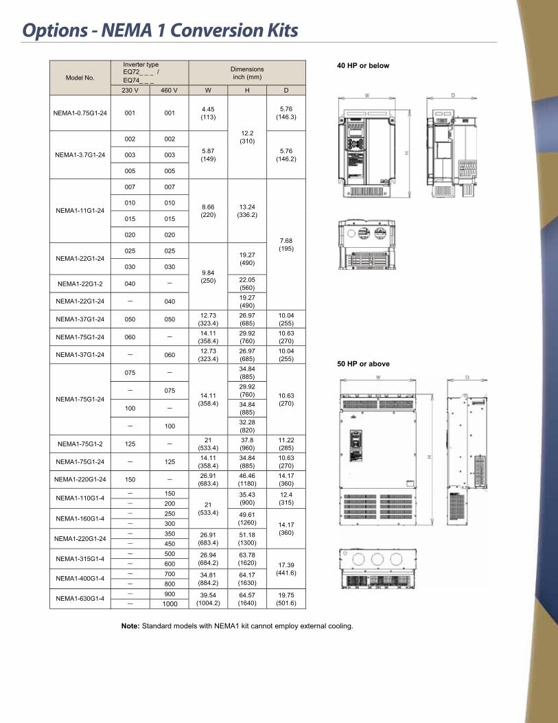
Options - NEMA 1 Conversion Kits
11-17
Inverter typeEQ72_ _ _ /EQ74_ _ _
Dimensions inch (mm)
40 HP or below
50 HP or above
230 V 460 V W H D
Model No.
NEMA1-0.75G1-24
NEMA1-3.7G1-24
NEMA1-11G1-24
NEMA1-22G1-24
NEMA1-22G1-24
NEMA1-37G1-24
NEMA1-37G1-24
NEMA1-75G1-24
NEMA1-75G1-24
NEMA1-220G1-24
NEMA1-110G1-4
NEMA1-160G1-4
NEMA1-220G1-24
NEMA1-315G1-4
NEMA1-400G1-4
NEMA1-630G1-4
NEMA1-75G1-2
NEMA1-75G1-24
NEMA1-22G1-2
4.45 (113)
12.2 (310)
001 001 5.76 (146.3)
002 002
5.87 (149)
5.76 (146.2) 003 003
005 005
007 007
8.66 (220)
13.24 (336.2)
7.68 (195)
010 010
015 015
020 020
025 025
9.84 (250)
19.27 (490) 030 030
040 22.05 (560)
- 040 19.27 (490)
050 050 12.73 (323.4)
26.97 (685)
10.04 (255)
060 -
-
14.11 (358.4)
29.92 (760)
10.63 (270)
- 060 12.73 (323.4)
26.97 (685)
10.04 (255)
075 -
14.11 (358.4)
34.84 (885)
10.63 (270)
- 075 29.92 (760)
100 - 34.84 (885)
- 100 32.28 (820)
125 - 21 (533.4)
37.8 (960)
11.22 (285)
- 125 14.11 (358.4)
34.84 (885)
10.63 (270)
150 - 26.91 (683.4)
46.46 (1180)
14.17 (360)
- 150
21 (533.4)
35.43 (900)
12.4 (315) - 200
- 250 49.61 (1260) 14.17
(360) - 300 - 350 26.91
(683.4) 51.18 (1300) - 450
- 500 26.94 (684.2)
63.78 (1620) 17.39
(441.6) - 600 - 700 34.81
(884.2) 64.17 (1630) - 800
- 900 39.54 (1004.2)
64.57 (1640)
19.75 (501.6) - 1000
Note: Standard models with NEMA1 kit cannot employ external cooling.

Options
Parts Name Type Remarks
EtherNet Card OPC-G1-ETH
The Ethernet option card allows for connectivity to various Ethernet protocols. These include: - EtherNet/IP - Modbus/TCP - BACnet/IP -Profinet-IOThe card also contains an embedded web server for configuration of numerous additional functions such as alarm evaluation with email notification, dashboard GUI with multiple windows for monitoring, virtual keypad interface, and protocol configuration.
DeviceNet Card OPC-G1-DEV
The DeviceNet option card allows for connectivity to a DeviceNet network. The card allows for control or monitoring of the inverter, monitor and change function codes, and the use of explicit messaging. The following are specifications for the DeviceNet options. - 64 Nodes, maximum, including the Master device. - Data rate (baud rate): 125 kbps, 250 kbps, 500 kbps - I/O Message: Polling and Change of State supported - Applicable Profile: AC Drive profile - Reading and writing all the function codes applicable to the EQ7 (I/O Message (User Defined Assembly Instance or Access to Function Codes Instance) and Explicit Message)This product has been tested by ODVA authorized Independent Test Lab and found to comply with ODVA’s DeviceNet Conformance Test Version 20.
PROFIBUS DP Card OPC-G1-PDP
The Profibus-DP option card allows for connectivity to a Profibus network. The card allows for control or monitoring of the inverter and for monitoring and changing of function codes. The following are specifications for the Profibus option. - PROFIBUS version: DP-V0 compliant - Transmission speed: 9,600 bps to 12 Mbps - Maximum network cable length per segment: 100 m (912 Mbps) to 1200 m (9.6kbps) - Applicable Profile: PROFIDrive V2 compliant
CANopen OPC-G1-COP
The CANopen is the card which supports various open bus types. With this card, the following operations can be per-formed using PC or PLC. - Operation frequency setting - Operation command setting (FWD, REV, RET, etc.) - Data code setting for each function code - Reading trip data
PG Interface Card (Supporting 12V)
OPC-G1-PG Having this card built-in to the inverter allows the speed control and the position control.
PG Interface Card (Supporting 5V)
OPC-G1-PG2 Having this card built-in to the inverter allows the speed control and the position control.
PG Synchronization Card OPC-G1-PG22 Velocity synchronization card, allowing both master and slave encoder inputs.
Digital Input Interface Card OPC-G1-DI Using this card allows frequency setting by 8, 12, 15, and 16 bits, and by BCD code.
Digital Output Interface Card OPC-G1-DOThe output interface card to be equipped with the EQ7, which allows monitoring frequency, output voltage, and output current with binary code.
Analog Input/Output Interface Card
OPC-G1-AIO Using this card allows the torque limit value input, frequency and frequency ratio setting with analog input.
Relay Communication Card OPC-G1-RY Using this card allows relay output of the inverter general output signal (transistor output).
Dynamic Braking Kits ----Dynamic braking resistors are available to match ratings for the entire product range. Dynamic braking transistors are available for all models above 40 hp.
Multiple system and network expansion modules are supported on a single EQ7 unit per the table below
Restrictions on mounting an optional card Y: Available N: Not Available
Mounting portOPC-G1S-
PG, PG2, PG22 D1,D0, A10, DEV RY ETH, TL, COP, PDP, CCL, SX
C PORT Y Y N N
B PORT N Y Y N
A PORT N Y Y Y
Remarks 1 2 3 2
Terminal block PCB
C PORT
B PORT
A PORT
Control PCB
*1 Any one of the above can be mounted on only C port.*2 Only one card can be mounted on any of A, B, or C ports. Cards can be mounted on DI, DO, and AIO ports at the same time, however, two identical cards cannot be allowed.*3 The cards can be mounted on both A and B ports. Two RY cards can be mounted at the same time. The number of RY contact points of a card is two. If three or four points are necessary, prepare two cards.Note: There are also restrictions on mounting when using the optional communications card. Contact us for details.Note: When mounting the IP40 option, only one optional card can be mounted. (RY card allows mounting of two cards.)

EQ7 Configured Packages
The EQ7 is available as the key unit in built-to-order packages for a variety of installations.
HVAC Packages TECO-Westinghouse offers a complete line of packaged drives, including bypass packages for fan and pump applications.
FEATURES
z UL508A z Packages up to 1000 hp available z Available in multiple disconnect options z Two or three contactor and soft start bypass z Custom design packages z Wide range of harmonic filters available to meet IEEE 519-1992 z NEMA 1, NEMA 12, NEMA 3R standard z NEMA 4 & 4X available z Duplex - multiplex packages available z Packages designed to customer specifications
APPLICATIONS
z Fans z Chillers z Refrigeration z Compressors z Air handlers z Pumps
Industrial Packages TECO-Westinghouse additionally offers packaged drives to suit even robust industrial applications.
FEATURES
z NEMA 1, NEMA 12, NEMA 3R standard z UL508A z Packages up to 1000 hp z Available in multiple disconnect options z NEMA 4, 4X available z Special Designs to meet tight spacing requirements
APPLICATIONS
z Conveyors z Compressors z Mixers z Stamping/ punch press

D-EQ7 2-13
TECO-Westinghouse Motor Company offers an extensive line of variable Speed Drives and Soft starts for your motor control applications.
We also offer a wide variety of motors that are matched with the Drives and soft Starters including vertical Hollow Shaft, Rolled steel, and NEMA Premium Efficient NEMA Motors.
From “in stock” controls to engineered systems, we can provide you the right control solution including an extensive line of TECO-Westinghouse AC Motors.
Contact us for your application and packaging needs!