feature extraction for electronic equipment...
TRANSCRIPT

MVA '98 IAPR Workshop on Machine Vision Applications, Nov. 17-19. 1998. Makuhari. Chiba. Japan
5-3 Feature Extraction for Electronic Equipment Manufacturing
Perfecto Marifio Electronic Technology Department and
Applied Electronics Institute University of Vigo 36200 Vigo, Spain
e-mail: [email protected] Fax: +34-986-469547 Tel: +34-986-8 12 162
Abstract
The authors have been involved in the implementation of a total quality control project in a communications equipment company, whose products are mounted and tested in a manufacturing plant controlled by an IBM Token Ring LAN.
The first implementation of total quality control project was an ATE (Automatic Test Equipment) LAN node that runs a program of verification for single-channel and multichannel electronic amplifiers.
The last implementation is an automated inspection LAN node based on artificial vision.
Miguel Angel Dominguez Electronic Technology Department and
Applied Electronics Institute University of Vigo 36200 Vigo, Spain.
e-mail: [email protected] Fax:+34-986-469547 Tel: +34-986-8 12 143
supported in its performance for a RF analyser connected to it through an IEEE 488 bus [5].
The last implementation is an automated inspection LAN node to detect the missing of SMT and non SMT components mounted in the electronic cards of above mentioned amplifiers. This LAN node for automated inspection is based on artificial vision [6] [7] and will be called MVI (Machine-Vision Inspection).
The first implementation is a case study of on- line/postprocess inspection because the ATE LAN node immediately follows the production process, whereas the last one based on artificial vision (MVI) is the type of on- linelin-process inspection [I], and therefore can be used in different stages along the mounting shop floor of the communications enterprise [8].
1 Introduction 2 Flexible Manufacturing System
Total quality control is performed at shop floor level along whole operations cycle performed over the product, from raw materials, through parts and semifinished shapes until its final shipping.
Automated inspection improves the data collection about the features and characteristics of products and processes, in order to assure production conformance to give specifications and to detect machine malfunctions or inaccuracies of logistic processes [I].
The authors have been involved in the implementation of a total quality control project in a communications equipment company [2], whose products are mounted and tested in a manufacturing plant controlled by an IBM Token Ring LAN [3]. The most significant products are RF and microwave amplifier boards for satellite TV receivers, with electronic components based on SMT technology [4].
The first implementation of total quality control project was an ATE (Automatic Test Equipment) LAN node that runs a program of verification for single-channel and multichannel electronic amplifiers, which bandwidth is in TV spectrum (50 + 850 MHz). This ATE LAN node is
The total quality control project of communications enterprise implemented over a flexible manufacturing system (FMS) [9], covers manufacturing activities over electronic amplifier boards provided with SMT components and devices, such as insertion of non SMT components, welding and screwing of them. The essential physical elements of this FMS are depicted in Fig. 1 : - Scara type robots from IBM [8] capable of performing
insertion, welding and screwing tasks, provided with adequate end effectors [lo], over the electronic amplifier boards.
- An automated material handling system to move the amplifier boards between robots and inspection stations, implemented through two conveyor belts. The main loop conveyor (MLC) provides boards with SMT electronic components and devices, to the robotic stations and the machine-vision inspection station (MVI). The secondary loop conveyor (SLC) supplies completely mounted boards, with SMT and non SMT components to the

COMWI'YICAnOI SERVER I
IN\FHIIO\ LOMWV\ICA I IOY \EH\'PH
Fig. I: FMS layout of co~n~nunications enterprise for automated mounting and inspection of electronic amplifier boards
automated test equipment station (ATE). - Automated storage and retrieval systems (ASIRSs) such
as: product identification system, part-washing devices for automatic removal of a fault board from conveyor belts, and a general feeding and cleaning pallet-based system of the two conveyor belts.
- Control elements connected through a Token Ring Local Area Network (LAN) that perform a shop floor distributed system, and therefore are LAN nodes with specific local tasks. The two conveyor belts are controlled by a Programmable Logic Controller (PLC). This PLC and the above mentioned production identification system are connected to LAN through a communications server [8]. The robot movings are controlled by a PC directly connected to it through an 110 card. The PC is under DOS and runs an only program, which is a programming language interpreter called AMLl2 [ l I]. A communication server can link until sixteen robots and thirty PLC's to the LAN [9].
3 Automatic Test Equipment
The specific local task managed for the ATE LAN node is the verification of amplifier boards mounted in the FMS of communications enterprise's shop floor. Amplifiers must be checked for each channel in next parameters: gain, maximum variations of gain, return loss and rejection of adjacent frequency.
The ATE station in the FMS besides its main task of testing electronic amplifier boards, is involved in the handling of these boards on the secondary loop. For that reason its hardware configuration is divided in two parts:
boards testing and handling elements (Figs. 2 and 3). The verification program is shown in Fig. 4.
4 Machine Vision LAN Node
The machine-vision inspection (MVI) node is devoted to detect the missing of SMT components and screws for clamping coaxial cables, when RF amplifier boards are mounted in the FMS (Fig. 1). Boards are checked by means of pictures which are tested if all board's defined components match a pattern of a previous correct image. If the matching is verified the board will pass to following FMS stages, otherwise a signal is activated to introduce the failed board in the part-washing device (Fig. 1). For this MVI node was developed a vision program that runs in a PC to which an Image Digitizing Card (IDC) is connected. The vision program controls this IDC, which performs the capture, processing, storage, and display of images taken by a videocamera (Fig. 5). This vision program defines the patterns and analyses the images of boards under test to decide if all pattern's components are present or not.
4.1 MVI structure
The MVI station is placed in the mounting stages of non SMT components, on the main loop conveyor of FMS. Its hardware configuration is (Fig. 5): - CCD videocamera model F450E from SONY that meets
CCIR PAL color standards. Its least lighting is 3 lux, and recommended lighting is higher than 100 lux. For this reason 4 lights with 60 wat of power each are used in order to emphasize the main physical characteristics of
PRINTER
C A
BRIDGE I TESTING ELEMENTS --------- I .PMUI I HANDLING ELEMENTS
FlXTllRlNG
TEST
ELECTRO-PNEUMATIC PLACEMENT
SYSTEM
:MECHANICAL COUPLING : ...-..--....-.....
Fig. 2: Connections of board testing and handling elements of ATE

SMT and non SMT components to detect over the amplifier board. The place where the amplifier boards, lights and videocamera are mounted for inspection must be closed with a mechanical structure that prevents the access of external light, in order to maintain constant the brightness conditions over the boards. Video output signal from videocamera is connected to IDC's J1 connector through a 75 ohm coaxial cable.
- Image digitizing card (IDC) from Data Translation called Vision-EZ model DT55-50 to 50 Hz, that allows to capture 50 frames per second (25 images per second). The digitizing resolution is 768x512 pixels, with 256 grey levels for point. This IDC allows with suitable software to capture, store, process and display images from videocameras or VCRs. The IDC has several input and output matrices called LUTs (Look-Up Tables) for processing images in real- time and their displaying in pseudo-colour. Exist 4 Input LUTs (ILUTs) and one Output LUT (OLUT) with 256 inputs. When an image is obtained it is routed through one of four ILUTs. These ILUTs can be programmed for passing the image unaltered or for implementing different processing hnctions such as multiply or division of images, intensity adjustment and reversing of images. After the image is stored in the card memory, each pixel can be accessed for particular operations. For its displaying the image is routed through the OLUT for assigning grey levels or pseudo-colour. Also exists one output table of overlaying (overlay OLUT) with 7 inputs, for giving coloration of overlaying to pixels. External trigger input for image acquisition from the PLC of FMS (Fig. I), and outputs for signals R, G and B and compound synchronism are connected to IDC's 52 connector. The cable to J2 connector has a 15 pins female connector for the IDC side and 9 pins male connector for signal adapter side. The J1 connector is a BNC input from videocamera.
PLCCORRECT
Fig. 3: Configuration of electro-pneumatic placement system and fixturing head of ATE on the secondary loop conveyor, including the part-washing
device
a) Main program
INITIALIZE VARIABLES
[NlTlALlZE GPlB COMMUNICATION
PARAMETERS
FILENAME O F RF ANALYZER
RF ANALYZER PROGRAMMING
b) Handling and testing subprogram
WAlT FOR PLUGGING
BOARD
SELECTOUTPUT
Calibration''
WMDOWS
HANDLR'I
TESTING OPERATIO
PRINT ATE REPORT f
CHANNEL MEASUREMENTS
MEASUREMENT 1 m 1 WAlT FOR
UNPLUGGING I
ESCAPE',
Fig. 4: Flowchart of verification program for ATE node
- Signal adapter that allows to conform output signals from IDC to an input signal for the euroconnector of RGB monitor. Adapts RGB and compound synchronism signals from IDC's J2 connector to a video compound signal that will be put in the euroconnector of RGB monitor.
- External RGB monitor of 14 inches model CEP 1497E from SANYO, with an euroconnector input for an external RGB signal from signal adapter. This RGB monitor displays images of RF amplifier boards provided by the videocamera, through the IDC.
- Personal Computer (PC) with the IDC connected to its ISAIAT bus of motherboard. Two signals are generated from a parallel port of PC (378H address) for the PLC of FMS (Fig. l), in order to be aware if RF amplifier boards are defective, and in this case remove them by means a part-washing device. In this PC runs the vision program

IN FMS
RGB monitor
Fig. 5: Hardware configuration of MVI station for quality control of mounted RF amplifier components
developed for this application of quality control, and the man-machine interface is supported by the keyboard and a VGA monitor. The external RGB monitor for images of RF amplifier boards is connected to PC through the IDC.
remains its twisted hole, which is translated to videocamera (Fig. 5) as a low lighting area, and the result in the IDC is a set of pixels with low grey level. On the contrary, when the screw is present, its metallic condition gives a deep brightness under the lights making a very clear area with high grey level. This is a very useful feature of PCB screws.
SMT components of PCB show a particular difficult for detection given its small size. Their shape is rectangular and are placed in the PCB crossing an insulating area that uncouples the two conductive strips, to which outermost parts of a SMT component are welded. This insulating area has an uniform dark green colour. When a SMT component is missing in a given area, the image taken by the IDC shows in that area a set of pixels with the same tonality. On the contrary, when the SMT component is present, in that area the IDC image has pixels with the same tonality related to the isolating area near SMT boundaries, and other pixels with more clear intensity level (white SMTs) or more dark one (black SMTs) related to SMT surface points. Therefore the SMT's detection over PCB will be based in this feature using gradient techniques.
4.3 Detection algorithms 4.2 Main features for detection
Printed circuit boards (PCBs) of RF amplifiers under inspection, have a big number of SMT and non SMT components and strips, that make difficult the task of their recognition and visual detection [6]. This multiplicity of elements and colour scheme changes make a high variation in grey levels of PCB image, and therefore binaryzations or filtering procedures over the image that would simplify notably the tasks of recognition and detection, are not suitable [7]. Visual control is even more complex given the shadows projected from metallic parts or in screw heads because its slots, taking a great significance the lighting applied over the PCB under inspection. Another problem is the existence of PCB areas where SMT components are very close, which makes very difficult their detection because the borders of a SMT component can be confused with neighbouring ones. Hence in PCB visual control must be involved besides the kind of element to be detected, the most changing characteristic of it from the situation of presence in the PCB to the missing one. In this quality control application the main elements to be detected are screws (non SMT) and SMT components.
In the PCBs under test there is a set of metallic brackets and cable terminals, and it is very important to know if insertion robots of FMS (Fig. 1) have put them or not. Given that each of these parts has a screw that hold down it against the PCB, the problem to detect the missing of any non SMT component can be reduced to check the presence or absence of its respective screw. When a screw is missing in the PCB
The vision program defines a pattern of PCB under test showing the areas where a component must exist. The SMT components are selected with a rectangular area moved over the whole image. This area is placed over a SMT component in such a way that the middle line which pass through the more narrow area cross to SMT from side to side by its half, just along the insulating strip under the SMT component. Points under this middle line are used for implementing the onedimensional gradient of pixels difference. In each point the gradient is calculated as the value of luminous intensity in the next point minus the same value in the previous point [grad(x) = I(x+l) - I(x-I)]. A positive gradient shows the change from a dark area to other clearest, and a negative gradient will show the opposite. For taking a decision about if a gradient exist in a given point, a level of 35 is selected. When a SMT component is missing, the obtained gradients over the middle line points are less than 35 because these points belong to the isolating strip and have similar tonality, therefore no gradient is got. On the contrary, if the SMT component exists, great level changes are detected in the two sides of it (higher than 35) and the obtained gradients detect the presence of SMT component. The explained gradient technique and its respective detection algorithm are depicted in Fig. 6.
For finding the presence of screws a technique based on grey levels is used. When a screw is present a high grey level is detected in that area, but its missing creates a low grey level area provided by the twisted hole. For selecting the screws a little square area is used with a size that allows

Line of gradients Line of gradients control Selection area con tion area
ulating st
Gradient
Fig. 6: Gradient technique and detection flowchart of SMT components
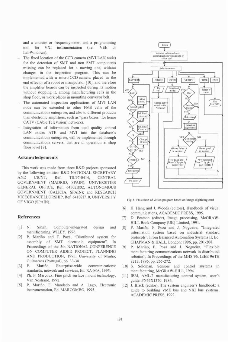
to include it inside the whole dark area when the screw is missing. Only are used the pixels from vertical line that cross the square by its half. The decision threshold is a grey level of 70. If there is no points from vertical line with a value higher than 70, no screw is in the area because all is dark. On the contrary if any point from vertical line has a value higher than 70, the screw is present given its metallic brightness. The explained grey level technique and its respective detection algorithm is stated in figure 7. Both techniques are used in the developed vision program of MVI (Fig. 8).
Line of grey levels control m Selection area
Twisting area of screw < , -
25.1 Level of grey 2551 Level of grey
decision level 7 0 , 7;p . 0
Pixels Pixels Grey level of decision line pixels Grey level of decision line pixels when the screw is missing when the screw is present
Fig. 7: Grey level technique and detection flowchart of non SMT components
stages, based on the exact location of defaults detected by MVI station.
- Just-In-Time (JIT) manufacturing methods are best supported by the feedback information provided by on- line inspection stations such as MVI and ATE.
- Low cost implementation of MVI and ATE stations doesn't affect to economy of "critical point" expenses derived of capital investments for FMS resources, and therefore a reduction of manufacturing costs is achieved, based in the best quality firnished to process and products in real-time.
5 Results 6 Conclusions
This total quality control project of FMS in the shop floor of communications enterprise is giving the next results: - Introduction of certified IS0 9000 quality for FMS based
on ATE and MVI performances, given the best and quick information provided about the manufacturing process.
On-linelpostprocess testing of final products (ATE), with a low rate of failed ones, because of implemented on- linefin-process inspection (MVI). Also failed products have been efficiently retrieved providing feedback mounting lines to previous manufacturing
New research and development tasks on the total quality control project of communications enterprise will be made in the following areas: - Change of ATE LAN node based on GPIB bus (IEEE
488) limited to a byte rate of 1 Mbyteslsec, to VXI based one with a mainframe able to control for instance type C instrumentation cards and byte rate over 100 Mbyteslsec [12]. This implementation could be based in two instrumentation cards such as a random signals generator
and a counter or frequencymeter, and a programming tool for VXI instrumentation ( e : VEE or Labwindows).
- The fixed location of the CCD camera (MVI LAN node) for the detection of SMT and non SMT components missing can be replaced for a moving one, without changes in the inspection program. This can be implemented with a micro CCD camera placed in the end effector of a robot or manipulator [lo], and therefore the amplifier boards can be inspected during its motion without stopping it, among manufacturing cells in the shop floor, or work places in mounting conveyor belt.
- The automated inspection applications of MVI LAN node can be extended to other FMS cells of the communications enterprise, and also to different products than electronic amplifiers, such as "pass boxes" for home CATV (CAble Television) networks.
- Integration of information from total quality control LAN nodes ATE and MVI into the database's communications enterprise, will be implemented through communications servers, that are in operation at shop floor level [8].
Acknowledgements
This work was made from three R&D projects sponsored by the following entities: R&D NATIONAL SECRETARY AND CICYT, Ref. TIC97-0414, CENTRAL GOVERNMENT (MADRID, SPAIN); UNIVERSITIES GENERAL OFFICE, Ref. 645021802, AUTONOMOUS GOVERNMENT (GALICIA, SPAIN); and RESEARCH VICECHANCELLORSHIP, Ref. 64 10217 10, UNIVERSITY OF VIGO (SPAIN).
References
[I] N. Singh, Computer-integrated design and manufacturing, WILEY, 1996.
[2] P. Mariiio and F. Poza, "Distributed system for assembly of SMT electronic equipment". In Proceedings of the 5th NATIONAL CONFERENCE ON COMPUTER AIDED PROJECT, PLANNING AND PRODUCTION, 1995, University of Minho, Guimaraes (Portugal), pp. 33-38.
[3] P. Mariiio, Enterprise-wide communications: standards, network and services, Ed. RA-MA, 1995.
[4] Ph. P. Marcoux, Fine pitch surface mount technology, Van Nostrand, 1992.
[S] P. Mariiio, E. Mandado and A. Lago, Electronic instrumentation, Ed. MARCOMBO, 1995.
(Begin) I Initialize values and open
commun~cations with dr~vers of I I vis~on card I
* Select~on menu I
Put code a Fig. 8: Flowchart of vision program based on image digitizing card
[6] H. Hang and J. Woods (editors), Handbook of visual communications, ACADEMIC PRESS, 1995.
[7] D. Pearson (editor), Image processing, McGRAW- HILL Book Company (UK) Limited, 199 1.
[8] P. Mariiio, F. Poza and J. Nogueira, "Integrated information system based on industrial standard protocols". From Balanced Automation Systems 11, Ed. CHAPMAN & HALL, London: 1996, pp. 201-208.
[9] P. Mariiio, F. Poza and J. Nogueira, "Flexible manufacturing communications network in distributed robotics". In Proceedings of the MHS'96, IEEE 96TH 8213, 1996, pp. 265-272.
[lo] S. Soloman, Sensors and control systems in manufacturing, McGRAW-HILL, 1994.
[ I l l IBM, AMLl2 manufacturing control system, user's guide, PN67X1370,1986.
[12] J. Black (editor), The system engineer's handbook: a guide to building VME bus and VXI bus systems, ACADEMIC PRESS, 1992.