feature detection and tracking with the dynamic and active ... · feature detection and tracking...
TRANSCRIPT

Feature Detection and Tracking with theDynamic and Active-pixel Vision Sensor (DAVIS)
David Tedaldi, Guillermo Gallego, Elias Mueggler and Davide Scaramuzza
Abstract— Because standard cameras sample the scene atconstant time intervals, they do not provide any informationin the blind time between subsequent frames. However, formany high-speed robotic and vision applications, it is crucialto provide high-frequency measurement updates also duringthis blind time. This can be achieved using a novel visionsensor, called DAVIS, which combines a standard camera andan asynchronous event-based sensor in the same pixel array.The DAVIS encodes the visual content between two subsequentframes by an asynchronous stream of events that convey pixel-level brightness changes at microsecond resolution. We presentthe first algorithm to detect and track visual features usingboth the frames and the event data provided by the DAVIS.Features are first detected in the grayscale frames and thentracked asynchronously in the blind time between frames usingthe stream of events. To best take into account the hybridcharacteristics of the DAVIS, features are built based on large,spatial contrast variations (i.e., visual edges), which are thesource of most of the events generated by the sensor. An event-based algorithm is further presented to track the features usingan iterative, geometric registration approach. The performanceof the proposed method is evaluated on real data acquired bythe DAVIS.
I. INTRODUCTION
Feature detection and tracking are the building blocks ofmany robotic and vision applications, such as tracking, struc-ture from motion, place recognition, etc. Extensive researchhas been devoted to feature detection and tracking withconventional cameras, whose operation principle is to tem-porally sample the scene at constant time intervals. However,conventional cameras still suffer from several technologicallimitations that prevent their use in high speed robotic andvision applications, such as autonomous cars and drones: (i)low temporal discretization (i.e., they provide no informationduring the blind time between consecutive frames), (ii) highredundancy (i.e., they wastefully transfer large amounts ofredundant information even when the visual content of thescene does not change), (iii) high latency (i.e., the timeneeded to capture and process the last frame). Since theagility of an autonomous agent is determined by the latencyand temporal discretization of its sensing pipeline, all theseadvantages put a hard bound on the maximum achievableagility of a robotic platform.
Bio-inspired event-based sensors, such as the DynamicVision Sensor (DVS) [1], [2], [3] or the Asynchronous Time-based Image Sensor (ATIS) [4], [5], [6], overcome the above-mentioned limitations of conventional cameras. In an event-
The authors are with the Robotics and Perception Group, Departmentof Informatics, University of Zurich, Switzerland—http://rpg.ifi.uzh.ch. This research was supported by the DARPA FLA Program andthe National Centre of Competence in Research Robotics (NCCR).
Fig. 1: Spatio-temporal view of the output of the DAVIS(frames and events) and the trajectories of the tracked fea-tures (in different colors, one for each feature). In this exam-ple, the scene consists of a rotating object. The motion in theblind time between consecutive frames is accurately trackedusing the stream of events; e.g., rotation is clearly visible inthe spiral-like trajectories of the event-based tracked features.To facilitate the visualization, only 10% of the events isdisplayed.
based sensor, each pixel operates independently of all otherpixels, and transmits asynchronously pixel-level brightnesschanges, called “events”, at microsecond resolution at thetime they occur. Hence, an event camera virtually eliminateslatency and temporal discretization. Also, it avoids redun-dancy, as no information is transmitted if the scene does notchange. However, this comes at a price: the output of an eventcamera (a stream of events) is fundamentally different fromthat of conventional cameras; hence, mature computer visionalgorithms cannot be simply adapted, and new, event-drivenalgorithms must be developed to exploit the full potential ofthis novel sensor.
More recently, hybrid vision sensors that combine thebenefits of conventional and event-based cameras have beendeveloped, such as the Dynamic and Active-pixel VIsionSensor (DAVIS) [7]. The DAVIS implements a standardgrayscale camera and an event-based sensor in the same pixelarray. Hence, the output consists of a stream of asynchronoushigh-rate (up to 1 MHz) events together with a stream ofsynchronous grayscale frames acquired at a low rate (ondemand and up to 24 Hz).
We present the first algorithm to detect features fromthe DAVIS frames and perform event-driven high-temporal
resolution tracking of these features in the blind time betweentwo frames. The key challenge consists of designing analgorithm that best takes into account the hybrid charac-teristics of the DAVIS output to solve the detection-and-tracking problem (Fig. 1). Since events are generated bychanges of brightness in the scenes, features are built basedon large, spatial contrast variations (i.e., visual edges), whichare the source of most of the events generated by the sensor.An event-based algorithm is further presented to track thefeatures using an iterative, geometric registration approach.
The paper is organized as follows. Section II reviews therelated work on event-based feature detection and tracking.Section III describes the DAVIS sensor. Section IV describesthe proposed detection and tracking algorithm. Section Vpresents the experimental results. Finally, section VI drawsthe conclusion and gives future perspectives.
II. RELATED WORK
A. From Frame-based to Event-based Tracking
Feature detection and tracking methods for frame-basedcameras are well-known [8], [9], [10]. The pixel intensitiesaround a corner point are used as a template that is comparedframe-by-frame with the pixels around the estimated positionof the corner point. The photometric error is then used toupdate the parameters describing the position and warpingof the template in the current frame. These appearance-based methods do not apply to event cameras; however, theapproach of using a parametric template model and updatingits parameters according to data fitting still applies.
From a high-level point of view, two relevant questionsregarding event-based tracking are what to track and howto track. The first question refers to how are the objects ofinterest modeled in terms of events so that object instancescan be detected in the event stream. The answer to this ques-tion is application dependent; the object of interest is usuallyrepresented by a succinct parametric model in terms of shapeprimitives. The second question, “how to track?”, then refersto how to update the parameters of the model upon thearrival of data events (caused by relative motion or by noise).For a system that answers the aforementioned questions,a third relevant question is “what kind of object motionsor distortions can be tracked?” The above-mentioned threequestions are key to understand existing tracking approaches.
B. Event-based Tracking Literature
Early event-based feature trackers were very simpleand focused on demonstrating the low-latency and low-processing requirements of event-driven vision systems,hence they tracked moving objects as clustered blob-likesources of events [11], [12], [13], [14], [15] or lines [16].
Accurate tracking of general shapes can be performed bycontinuously estimating the warping between the model andthe events. This has been addressed and demonstrated forarbitrary user-defined shapes using event-based adaptions ofthe Iterative Closest Point (ICP) algorithm [17], gradientdescent [18], or Monte-Carlo methods [19] (i.e., by matchingevents against a uniformly-sampled collection of rotated and
scaled versions of the template). Detection and tracking oflocally-invariant features, such as corners, directly from eventstreams has been addressed instead in [20].
Notice, however, that all above-mentioned papers weredeveloped for event-only vision sensors. In this paper, webuild upon these previous works and present the first algo-rithm to automatically detect features from the DAVIS framesand perform event-driven high-temporal resolution trackingof these features in the blind time between two frames.
III. THE DYNAMIC AND ACTIVE-PIXEL VISION SENSOR
The DAVIS [7] is a novel vision sensor combining aconventional frame-based camera (active pixel sensor - APS)and a DVS in the same array of pixels. The global-shutterframes provide absolute illumination on demand and up to24 Hz, whereas the event sensor responds asynchronouslyto pixel-level brightness changes, independently for eachpixel. More specifically, if I(t) is the illumination sensedat pixel (x, y) of the DVS, an event is triggered if relativebrightness change exceeds a global threshold: |∆ ln I| :=| ln I(t) − ln I(t − ∆t)| > C, where ∆t is the time sincethe last event was triggered (at the same pixel). An eventis a tuple e = (x, y, t, p) that conveys the spatio-temporalcoordinates (x, y, t) and sign (i.e., polarity p = ±1) of thebrightness change. Events are time-stamped with microsec-ond resolution and transmitted asynchronously when theyoccur, with very low latency 15 µs. The DAVIS has a veryhigh dynamic range (130 dB) compared with the 70 dB ofhigh-quality, traditional image sensors. The low latency, thehigh temporal resolution, and the very high dynamic rangemake the DAVIS extremely advantageous for future roboticapplications in uncontrolled natural lighting, i.e., real-worldscenarios.
A sample output of the DAVIS is shown in Fig. 1. Thespatial resolution of the DAVIS is 240× 180 pixels. This isstill limited compared to the spatial resolution of state-of-the-art conventional cameras. Newer sensors, such as the colorDAVIS (C-DAVIS) [21] will have higher spatial resolution(640× 480 pixels), thus overcoming current limitations.
IV. FEATURE DETECTION AND TRACKINGWITH THE DAVIS
Since events are generated by changes of brightness, thisimplies that only edges are informative. Intersecting edgescreate corners, which are “features” that do not suffer fromthe aperture problem and that have been proven to be opti-mally trackable in frame-based approaches [10]. Therefore,event-based cameras also allow for the perception of corners,as shown in [20]. We exploit these observations to extractand describe features using the DAVIS frames, and then trackthem using the event stream, as illustrated in Fig. 2. Ourmethod builds upon the customized shapes in [19] and theupdate scheme in [17]. The technique comprises to mainsteps: feature detection and tracking, as we detail in the nextsections.

(a) (b) (c) (d)
Fig. 2: Feature detection and tracking. (a) Frame with centers of detected features (green crosses). (b) Edge map (black andwhite) and square patches defining the features (i.e, model point sets, in red) (b)-(c) Zoomed views of the data point sets(i.e., events; blue circles) and model point sets (red stars) of the features, shortly after initialization.
Algorithm 1 High temporal resolution tracking
Feature detection:- Detect corner points on the frame (Harris detector).- Run Canny edge detector (returns a binary image, 1 ifedge pixel; 0 otherwise).- Extract local edge-map patches around corner points, andconvert them into model point sets.Feature tracking:- Initialize a data point set per patchfor each incoming event do
- Update the corresponding data point set.for each corresponding data point set do
- Estimate the registration parameters between thedata and the model point sets.
- Update registration parameters of the model points.
A. Feature Detection From Frames
The absolute brightness frames of the DAVIS are usedto detect edges (e.g., Canny’s method [22]) and corners(e.g., Harris detector [23]). Around the strongest corners,we use the neighboring pixels of the Canny edge-map todefine patches containing the dominant source of events. Wesimplify the detection by converting the edge-map patchesto binary masks indicating the presence (1) or absence (0)of an edge. The binary masks define the interest shapes fortracking in terms of 2D point sets, called “model point sets”.These steps are summarized at the beginning of Algorithm 1.
We use square patches of the same size, which is anadjustable parameter. However, it is straightforward to extendthe method to consider different aspect ratios and sizes.
Frames are not required to be provided at a constant ratesince they are only used to initialize features; they can beacquired on demand to replace features that are lost or fallout of the field of view of the sensor.
B. Feature Tracking From the Event Stream
Extracted features are tracked using subsequent eventsfrom the DAVIS. The input to the event-based trackingalgorithm consists of multiple, local model point sets. Thesecond part of Algorithm 1 summarizes our tracking strategy.
1) Sets of Events used for Feature Registration: For everyfeature, we define a data point set of the same size as themodel point set. Therefore, the size can be different forevery feature, depending on edge information. Data point setsconsist of local space-time subsets of the incoming events:an event is inserted in a data point set if the event coordinatesare inside the corresponding patch. Once a data point set hasbeen filled, registration of the point sets can be done. Hence,a data point set defines the set of events that are relevantfor the registration of the associated feature. Registrationis carried out by minimization of the distance between thedata and the model point sets, as explained next. Data pointsets are continuously updated: the newest event replaces theoldest one and the registration iteration proceeds.
This procedure is event-based, i.e., the parameters of thetracked feature are updated every time an incoming eventis considered relevant for that feature. The algorithm isasynchronous by design, and can process multiple featuressimultaneously. Several strategies to assign an incomingevent to one or more overlapping patches can be used, ina way similar to [18]. We updated all models around theambiguous event.
2) Registration: The data point set from the events, {pi},is registered to the model point set (feature), {mi}, byminimization of the Euclidean distance between the sets, andincluding outlier rejection:
arg minA
∑(pi,mi)∈Matches
‖A(pi)−mi‖2, (1)
where A is the registration transformation between thematched point sets. For simplicity, we choose A within theclass of Euclidean motions, but the method can be extendedto more complex transformations. We choose the iterativeclosest point algorithm (ICP) [24] to minimize (1). Matchespi ↔ mi are established according to nearest neighbor; apredefined distance of 2 pixels between the events in the datapoint set and the model point set is used for outlier rejection.Each algorithm iteration has three stages: first, candidatematches are established, then the geometric transformationis estimated, and, finally, the transformation is applied tothe model point set. The operation proceeds until the errordifference between two consecutive iterations is below acertain threshold.
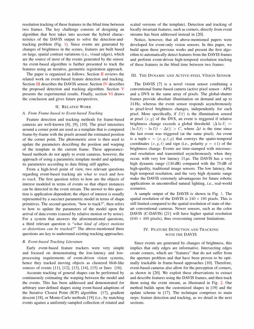
(a) Before registration (b) After registration
Fig. 3: A feature tracker, with the model point set (in red), thedata point set (in blue). Same color notation as in Figs. 2c-2d. The black square represents the patch around the modelpoint set. (a) Before registration: the current event (in green)updates the data point set and is used for registration of thepoint sets. (b) After registration: the events marked in yelloware classified as outliers, and the registration parameters areupdated, aligning the model and data point sets.
Fig. 3a shows both the model and the data point sets. Whena new event arrives, the geometric transformation that definesthe tracker is updated according to the minimization of (1).The result is depicted in Fig. 3b. By discounting the pointsclassified as outliers by the algorithm (in yellow), registrationis accurate. Feature trajectories are given by the positions ofthe features returned by the registration step.
Due to the high temporal resolution of the DAVIS, thetransformation between consecutive events (in the samefeature) is close to the identity (Fig. 3b), and so, our methodyields good results even after a single iteration. In practice,it is more efficient to compute the registration transformationevery M events, e.g., of half the size of the model point set.
V. EXPERIMENTS
We present the tests performed to validate the algorithmand to study its performance in different scenes with increas-ing level of complexity: a very large contrast (i.e., blackand white) scene, a piecewise constant scene (a cartoon),and a natural scene (the leaves of a tree; see Fig. 11). Thefirst scene depicts a black star on a white background; thisscene has sharp transitions between the two intensity levels,showing clear edges (Fig 1) and well-localized features. Thesecond scene consists of a cartoon image with piecewiseconstant regions (Fig 8a); intensity is concentrated in a fewgrayscale levels and there are moderately abrupt transitionsbetween them. The third scene is a representative of a naturalimage, rich in texture and brightness changes of differentmagnitudes (Fig. 11a) coming from the leaves of a tree. Thescene datasets show dominant translational and rotationalmotions.
We used patches of 25×25 pixels, which is approximately1/10 of the image width. This size was empirically found tobe best for a broad class of scenes.
We measured the tracking error over time. The trackingerror is computed against ground truth, which was generated
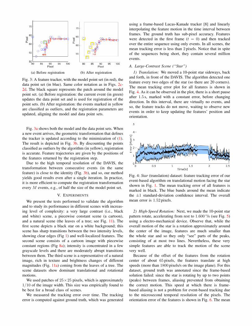
using a frame-based Lucas-Kanade tracker [8] and linearlyinterpolating the feature motion in the time interval betweenframes. The ground truth has sub-pixel accuracy. Featureswere detected in the first frame (t = 0) and then trackedover the entire sequence using only events. In all scenes, themean tracking error is less than 2 pixels. Notice that in spiteof the sequences being short, they contain several millionevents.
A. Large-Contrast Scene (“Star”)
1) Translation: We moved a 10-point star sideways, backand forth, in front of the DAVIS. The algorithm detected onefeature every two edges of the star (so there are 20 corners).The mean tracking error plot for all features is shown inFig. 4. As it can be observed in the plot, there is a short pauseafter 1.5 s, marked with a constant error, before changingdirection. In this interval, there are virtually no events, andso, the feature tracks do not move, waiting to observe newevents in order to keep updating the features’ position andorientation.
Fig. 4: Star (translation) dataset: feature tracking error of ourevent-based algorithm on translational motion facing the starshown in Fig. 1. The mean tracking error of all features ismarked in black. The blue bands around the mean indicatethe ±1 standard-deviation confidence interval. The overallmean error is 1.52 pixels.
2) High-Speed Rotation: Next, we made the 10-point starpattern rotate, accelerating from rest to 1.600 °/s (see Fig. 5)using a electro-mechanical device. Observe that, while theoverall motion of the star is a rotation approximately aroundthe center of the image, features are much smaller thanthe whole star and so they only “see” parts of the peaks,consisting of at most two lines. Nevertheless, these verysimple features are able to track the motion of the scenevery well.
Because of the offset of the features from the rotationcenter of about 65 pixels, the features translate at highspeeds (more than 1800 pixels/s on the image plane). For thisdataset, ground truth was annotated since the frame-basedsolution failed: since the star is rotating by up to two points(peaks) between frames, aliasing prevented from obtainingthe correct motion. This speed at which there is frame-based aliasing is not a problem for event-based tracking dueto the microsecond temporal resolution of the pixels. Theorientation error of the features is shown in Fig. 6. The mean

orientation error remains below 20° over more than two fullrevolutions, leading to a relative error of 2.3 %. The featuretracks form spirals in image space-time, as shown in Fig. 7.All of the 20 features (one per vertex) of the 10-point starwere accurately tracked during the entire sequence.
Fig. 5: Star (rotation) dataset: angular speed of rotating star.With an approximately constant acceleration (i.e., linear ve-locity profile), the angular speed reaches more than 1600 °/s.
Fig. 6: Star (rotation) dataset: feature tracking error of ourevent-based algorithm on the dataset shown in Fig. 1. Themean tracking error of all features is marked in black.The blue bands around the mean indicate the ±1 standard-deviation confidence interval. The overall mean error is 6.3°.
Fig. 7: Star (rotation) dataset: space-time locations of thefeatures. Due to the rotation of the star, the feature tracksform spirals. The spiral step gets smaller as the angular speedincreases, in this case, with constant acceleration.
B. Cartoon Scene (“Lucky Luke”)Fig. 8 shows several snapshots of the tracked features on
a sequence of the cartoon scene. The dominant motion is ahorizontal translation, back and forth. We observe that 81features well distributed in the object are correctly trackedthroughout the event stream. The tracking error is reported inFig. 9. As observed in the plot, there is a short pause after1 s (constant error), before changing the motion direction.A slight increase of the error can be observed when themotion resumes. However, the mean error in this part of themotion is less than 2 pixel and the overall mean error is small:1.22 pixel. Tracking in this scene is very good due to tworeasons: (i) most of the events are located at the strong edges,which are captured by the features, and regions of constantintensity do not generate events. (ii) there are more than twoedges per feature, and with a complex shape (edges in severaldirections) that make them distinctive for alignment. Thetracked features in image space-time are shown in Fig. 10.
Fig. 9: Lucky Luke dataset: feature tracking error of ourevent-based algorithm. The mean tracking error of all fea-tures is marked in black. The blue bands around the meanindicate the ±1 standard-deviation confidence interval. Theoverall mean error is 1.22 pixels.
Fig. 10: Lucky Luke dataset: space-time view in the imageplane of the tracked features’ trajectories. The sidewaysmotion is clearly visible in the feature trajectories.
(a) DAVIS frame for initializa-tion.
(b) Events (white over black) andfeatures (solid colors) shortly af-ter initialization.
(c) Features during motion. (d) Features during motion, at alater time than (c).
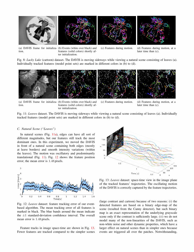
Fig. 8: Lucky Luke (cartoon) dataset. The DAVIS is moving sideways while viewing a natural scene consisting of leaves (a).Individually tracked features (model point sets) are marked in different colors in (b) to (d).
(a) DAVIS frame for initializa-tion.
(b) Events (white over black) andfeatures (solid colors) shortly af-ter initialization.
(c) Features during motion. (d) Features during motion, at alater time than (c).
Fig. 11: Leaves dataset. The DAVIS is moving sideways while viewing a natural scene consisting of leaves (a). Individuallytracked features (model point sets) are marked in different colors in (b) to (d).
C. Natural Scene (“Leaves”)
In natural scenes (Fig. 11a), edges can have all sort ofdifferent magnitudes, but our features still track the mostdominant ones. In this experiment, we moved the DAVISin front of a natural scene containing both edges (mostlyat leave borders) and smooth intensity variations (withinthe leaves). The motion was oscillatory and predominantlytranslational (Fig. 11). Fig. 12 shows the feature positionerror; the mean error is 1.48 pixels.
Fig. 12: Leaves dataset: feature tracking error of our event-based algorithm. The mean tracking error of all features ismarked in black. The blue bands around the mean indicatethe ±1 standard-deviation confidence interval. The overallmean error is 1.48 pixels.
Feature tracks in image space-time are shown in Fig. 13.Fewer features are tracked compared to the simpler scenes
Fig. 13: Leaves dataset: space-time view in the image planeof the tracked features’ trajectories. The oscillating motionof the DAVIS is correctly captured by the feature trajectories.
(large contrast and cartoon) because of two reasons: (i) thedetected features are based on a binary edge-map of thescene (resulted from the Canny detector), but such binarymap is an exact representation of the underlying grayscalescene only if the contrast is sufficiently large. (ii) we do notmodel many of the non-linearities of the DAVIS, such asnon-white noise and other dynamic properties, which have alarger effect on natural scenes than in simpler ones becauseevents are triggered all over the patches. Notwithstanding,

for some robotics applications there is no need to track manyfeatures; for example, in perspective-N-point problems) it issufficient to track as few as three features [25].
Notice that, overall, all the experiments show that ourproposed and automatically-detected features can be trackedfor a considerable amount of time, much larger than thetime between consecutive frames. Hence, lost features (e.g.,falling out of the field of view) could be replaced by newones that would be initialized using frames at a much lowerrate (e.g. 1 Hz) or on demand.
Our method has been tested with real data, with differenttypes of motion, and the results show accurate tracking (lessthan 2 pixels mean error). Better and more accurate resultscould be obtained by incorporating the edge strength and theevent generation model.
VI. CONCLUSIONS
We have developed a high-temporal tracking algorithmfor hybrid sensors such as the DAVIS. We used principledarguments of event data generation to justify our choice ofrelevant features to track, and proposed a pipeline to extractthose features from the frames. Then we used an event-based tracking algorithm that exploits the asynchronousand high temporal resolution of the event stream. In ourmethod, features are automatically and accurately initialized,and are adapted to the scene content, thus overcoming theshortcomings of existing methods. We tested the algorithmon real data from several sequences, and the results validatethe approach.
Inspired by the achieved tracking accuracy, we intend tobuild a visual-odometry pipeline on top of this event-basedfeature tracking method. Finally, the frames used in ouralgorithm to initialize the features suffer from motion blurand limited dynamic range, as in any standard camera. Toovercome these limitations, we plan to investigate methodsto extract features directly from the event stream.
ACKNOWLEDGMENTWe thank Tobi Delbruck for providing the DAVIS240C
and Beat Kueng for helping with data recording.
REFERENCES
[1] P. Lichtsteiner, C. Posch, and T. Delbruck, “A 128x128 120dB 30mWasynchronous vision sensor that responds to relative intensity change,”in Solid-State Circuits Conference, 2006. ISSCC 2006. Digest ofTechnical Papers. IEEE International, Feb 2006, pp. 2060–2069.
[2] ——, “A 128x128 120 dB 15 µs latency asynchronous temporalcontrast vision sensor,” IEEE J. of Solid-State Circuits, vol. 43, no. 2,pp. 566–576, 2008.
[3] T. Delbruck, B. Linares-Barranco, E. Culurciello, and C. Posch,“Activity-driven, event-based vision sensors,” in IEEE Intl. Symp. onCircuits and Systems (ISCAS), May 2010, pp. 2426–2429.
[4] C. Posch, D. Matolin, and R. Wohlgenannt, “An asynchronous time-based image sensor,” in IEEE Intl. Symp. on Circuits and Systems(ISCAS), May 2008, pp. 2130–2133.
[5] ——, “A QVGA 143dB dynamic range asynchronous address-eventPWM dynamic image sensor with lossless pixel-level video compres-sion,” in Solid-State Circuits Conference Digest of Technical Papers(ISSCC), 2010 IEEE International, Feb 2010, pp. 400–401.
[6] ——, “A QVGA 143 dB Dynamic Range Frame-Free PWM ImageSensor With Lossless Pixel-Level Video Compression and Time-Domain CDS,” IEEE J. of Solid-State Circuits, vol. 46, no. 1, pp.259–275, Jan 2011.
[7] C. Brandli, R. Berner, M. Yang, S.-C. Liu, and T. Delbruck, “A240x180 130dB 3us Latency Global Shutter Spatiotemporal VisionSensor,” IEEE J. of Solid-State Circuits, 2014.
[8] B. D. Lucas and T. Kanade, “An iterative image registration techniquewith an application to stereo vision,” in Proc. 7th Int. Joint Conf. onArtificial Intelligence (IJCAI) - Volume 2, 1981, pp. 674–679.
[9] C. Tomasi and T. Kanade, “Detection and tracking of point features,”Carnegie Mellon University, Tech. Rep., 1991.
[10] J. Shi and C. Tomasi, “Good features to track,” in Computer Visionand Pattern Recognition, 1994. Proceedings CVPR ’94., 1994 IEEEComputer Society Conference on, June 1994, pp. 593 –600.
[11] M. Litzenberger, C. Posch, D. Bauer, A. Belbachir, P. Schon, B. Kohn,and H. Garn, “Embedded vision system for real-time object trackingusing an asynchronous transient vision sensor,” in Digital SignalProcessing Workshop, 12th - Signal Processing Education Workshop,4th, Sept 2006, pp. 173–178.
[12] M. Litzenberger, A. Belbachir, N. Donath, G. Gritsch, H. Garn,B. Kohn, C. Posch, and S. Schraml, “Estimation of vehicle speedbased on asynchronous data from a silicon retina optical sensor,” inIntelligent Transportation Systems Conference, 2006. ITSC ’06. IEEE,Sept 2006, pp. 653–658.
[13] T. Delbruck and P. Lichtsteiner, “Fast sensory motor control based onevent-based hybrid neuromorphic-procedural system,” in IEEE Intl.Symp. on Circuits and Systems (ISCAS), May 2007, pp. 845–848.
[14] T. Delbruck and M. Lang, “Robotic goalie with 3ms reaction time at4% CPU load using event-based dynamic vision sensor,” Frontiers inNeuroscience, vol. 7, no. 223, 2013.
[15] E. Piatkowska, A. Belbachir, S. Schraml, and M. Gelautz, “Spatiotem-poral multiple persons tracking using Dynamic Vision Sensor,” inIEEE Comput. Soc. Conf. on Computer Vision and Pattern RecognitionWorkshops (CVPRW), June 2012, pp. 35–40.
[16] J. Conradt, M. Cook, R. Berner, P. Lichtsteiner, R. Douglas, andT. Delbruck, “A Pencil Balancing Robot using a Pair of AER DynamicVision Sensors,” in IEEE Intl. Symp. on Circuits and Systems (ISCAS),2009.
[17] Z. Ni, A. Bolopion, J. Agnus, R. Benosman, and S. Regnier, “Asyn-chronous Event-Based Visual Shape Tracking for Stable Haptic Feed-back in Microrobotics,” IEEE Trans. Robotics, vol. 28, pp. 1081–1089,2012.
[18] Z. Ni, S.-H. Ieng, C. Posch, S. Regnier, and R. Benosman, “VisualTracking Using Neuromorphic Asynchronous Event-Based Cameras,”Neural Computation, vol. 27, pp. 925–953, 2015.
[19] X. Lagorce, C. Meyer, S.-H. Ieng, D. Filliat, and R. Benosman,“Asynchronous Event-Based Multikernel Algorithm for High-SpeedVisual Features Tracking,” IEEE Trans. Neural Networks and LearningSystems, vol. 26, no. 8, pp. 1710–1720, Aug 2015.
[20] X. Clady, S.-H. Ieng, and R. Benosman, “Asynchronous event-basedcorner detection and matching,” Neural Networks, vol. 66, pp. 91 –106, 2015.
[21] C. Li, C. Brandli, R. Berner, H. Liu, M. Yang, S. Liu, and T. Delbruck,“An RGBW Color VGA Rolling and Global Shutter Dynamic andActive-Pixel Vision Sensor,” in International Image Sensor Workshop(IISW), Vaals, Netherlands, June 2015.
[22] J. Canny, “A computational approach to edge detection,” IEEE Trans.Pattern Anal. Machine Intell., vol. 8, no. 6, pp. 679–698, Nov 1986.
[23] C. Harris and M. Stephens, “A combined corner and edge detector,”in Proceedings of The Fourth Alvey Vision Conference, vol. 15.Manchester, UK, 1988, pp. 147–151.
[24] P. Besl and N. D. McKay, “A method for registration of 3-D shapes,”IEEE Trans. Pattern Anal. Machine Intell., vol. 14, no. 2, pp. 239–256,1992.
[25] L. Kneip, D. Scaramuzza, and R. Siegwart, “A novel parametrizationof the perspective-three-point problem for a direct computation ofabsolute camera position and orientation,” in Proc. IEEE Int. Conf.Computer Vision and Pattern Recognition, 2011, pp. 2969–2976.