feasibility study university of illinois at urbana … · solar project feasibility study summary...
TRANSCRIPT

Engineering | Planning | Allied Services
Krannert Center for the Performing Arts
Solar Project Feasibility Study University of Illinois at Urbana-Champaign Project Number: U12239
Summary of Findings March 25, 2014
Phase 1 March 1, 2013 (revised August 29, 2013)
Phase 2 95% Submittal March 25, 2014

UIUC Project No.: U12239 March 25, 2014 Krannert Center for Performing Arts Solar Project Feasibility Study
SUMMARY OF FINDINGS This Feasibility study considers the potential placement of a Photovoltaic array on the roof of Krannert Center for the Performing Arts (KCPA). The Study was conducted in two phases, the reports of which are included herein. A construction budget of five hundred eighty-five thousand dollars ($585,000), excluding contingencies, was proposed by the Student Sustainability Committee. Based on shadow studies, it was determined that placement of a photovoltaic array on the roof of the Great Hall would maximize the potential power gain, as compared to other locations at KCPA. However, structural analyses have shown that the roof structure would require strengthening prior to the application of any new load. Additionally, based on its age, it is recommended that the roofing be replaced prior to the installation of a photovoltaic array. Access to the roof is cumbersome, and is also in need of improvement. The opinion of probable construction cost for this associated work exceeds the five hundred eighty-five thousand dollar ($585,000) construction budget. Without considering these associated projects in the payback analysis, the complexities of constructing a PV array on the roof structure diminish the economical effectiveness of a roof mounted PV array as compared to a ground-mounted system, assuming the ready availability of real estate. Based on these findings, it is the recommendation of Hanson Professional Services Inc. (Hanson) that a photovoltaic array not be placed on the roof of the Great Hall at KCPA, and that consideration be given instead to directing the available funds to a location that is more readily suited to its construction. The following matrix captions the primary Objectives of the study, and directs the reader to the Section(s), Article(s) and / or Appendix(ces) in the Study that addresses the objective. A recapitulation of the Opinions of Probable Construction cost is also presented.
OBJECTIVE
REFERENCE ARTICLE
OR SECTION
COMMENTARY
PHASE 1 PHASE 2
1. Conduct project kick-off meeting with University personnel (KCPA and Facilities & Services).
Kick-off meeting was held January 18, 2013 at UIUC.
2. Review record documents of existing construction for the study areas and existing information on PV project feasibility.
Existing Plans, circa 1966 and 1967. Architect: Harrison & Abramovitz. Structural Engineers: Lev Zetlin & Associates. Mechanical/Electrical Engineers: Cosentini Associates
I:\11jobs\11G0002I\Admin\14-Reports\Phase 2\Summary of Findings.docx

UIUC Project No.: U12239 March 25, 2014 Krannert Center for Performing Arts Solar Project Feasibility Study
OBJECTIVE
REFERENCE ARTICLE
OR SECTION
COMMENTARY
PHASE 1 PHASE 2
3. Perform site survey of the study areas and identify probable installation locations of exterior solar PV arrays and interior PV inverters. Locations will be assessed for future system maintenance and connection to the commercial power grid.
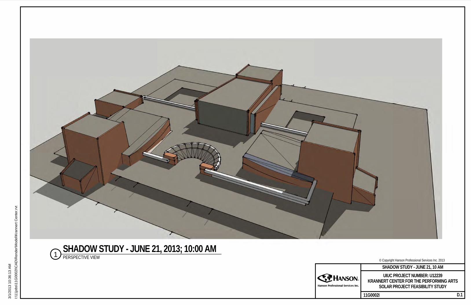
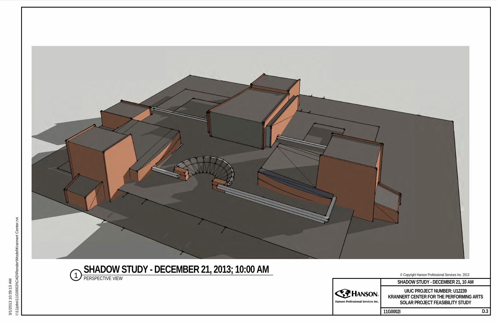
Site Visits performed on February 15, 2013. PV information identified in Section 5. Design Concepts, pp. 8-9. Appendix D – Shadow Studies
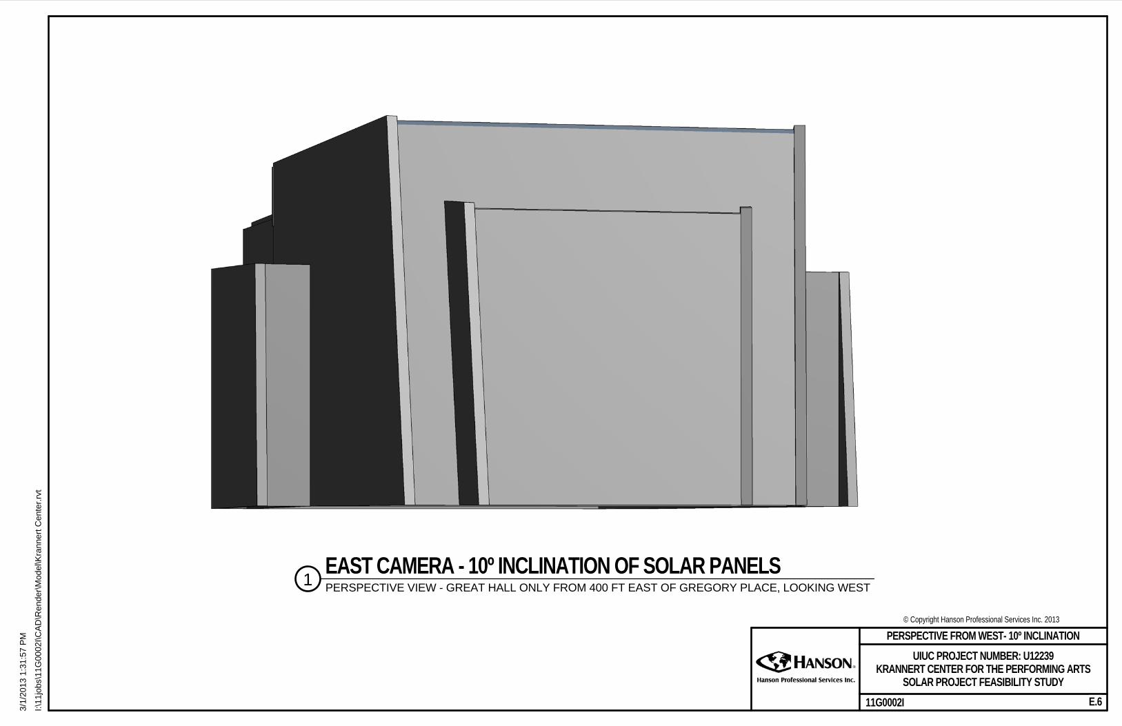
Shadow studies directed PV placement array on roof of Great Hall. 10 degree angle of inclination of PV array selected for aesthetic considerations.
4. Identify probable PV system size and number, type and size of PV arrays based on preliminary project construction budget for input on the rendering.
Section 5. Design Concepts, pp. 8-9 Appendix C – Schematic Roof Plan – Great Hall
5. Produce a preliminary report including a summary of initial findings and three exterior renderings of the facility depicting the visual impact the installation would be expected to have on the KCPA. The renderings will be produced in Revit by modeling the PV system design then overlaying that geometry onto three KCPA building photographs taken from the South, East, and West points of view.
Draft Report produced March 1, 2013. Renderings – Appendix E – Renderings – Line Type for Great Hall at 34° and 10° Inclination of Solar Panels and Overall ground Level Photo Renderings
6. Respond to the University’s review comments and meet with University personnel to disposition those comments.
Responded to UIUC’s comments on March 29, 2013. Phase 1 Report - Appendix I – UIUC Review Comments
I:\11jobs\11G0002I\Admin\14-Reports\Phase 2\Summary of Findings.docx

UIUC Project No.: U12239 March 25, 2014 Krannert Center for Performing Arts Solar Project Feasibility Study
OBJECTIVE
REFERENCE ARTICLE
OR SECTION
COMMENTARY
PHASE 1 PHASE 2
7. Update report and submit final preliminary report copy.
Revised Report and submitted to UIUC August 29, 2013.
Phase 2 report – Submitted March 25, 2014.
8. Evaluate existing electrical system to determine appropriate location to interconnect PV system. Determine maximum available solar power that can be effectively connected to the existing electrical system based on the available mounting area for the solar modules.
Section 5. Design Concepts – pp. 8 – 9.
Micro-inverters are proposed to be located at the PV array on the roof. New power distribution panel would be located on the Booth level. Maximum anticipated power generation = 80KW.
9. Evaluate the capacity of the existing roof structure to support the gravity and wind loads induced into the structure by the PV arrays.
Initial Findings – Article 1.5 Special Conditions, p. 6.
Section 1. Structural Evaluation, pp. 4-7.
Strengthening of existing structure is required prior to placement of PV array. OPCC is $300,000.
10. Evaluate the general condition of the existing roofing materials for the study areas to determine the anticipated remaining useful life of the roof(s).
Initial Findings – Article 1.5 Special Conditions, pp. 5 and 6.
Section 2. Roofing Replacement, p. 7.
Roofing replacement is recommended. OPCC is $360,000.
I:\11jobs\11G0002I\Admin\14-Reports\Phase 2\Summary of Findings.docx
UIUC Project No.: U12239 March 25, 2014 Krannert Center for Performing Arts Solar Project Feasibility Study
OBJECTIVE
REFERENCE ARTICLE
OR SECTION
COMMENTARY
PHASE 1 PHASE 2
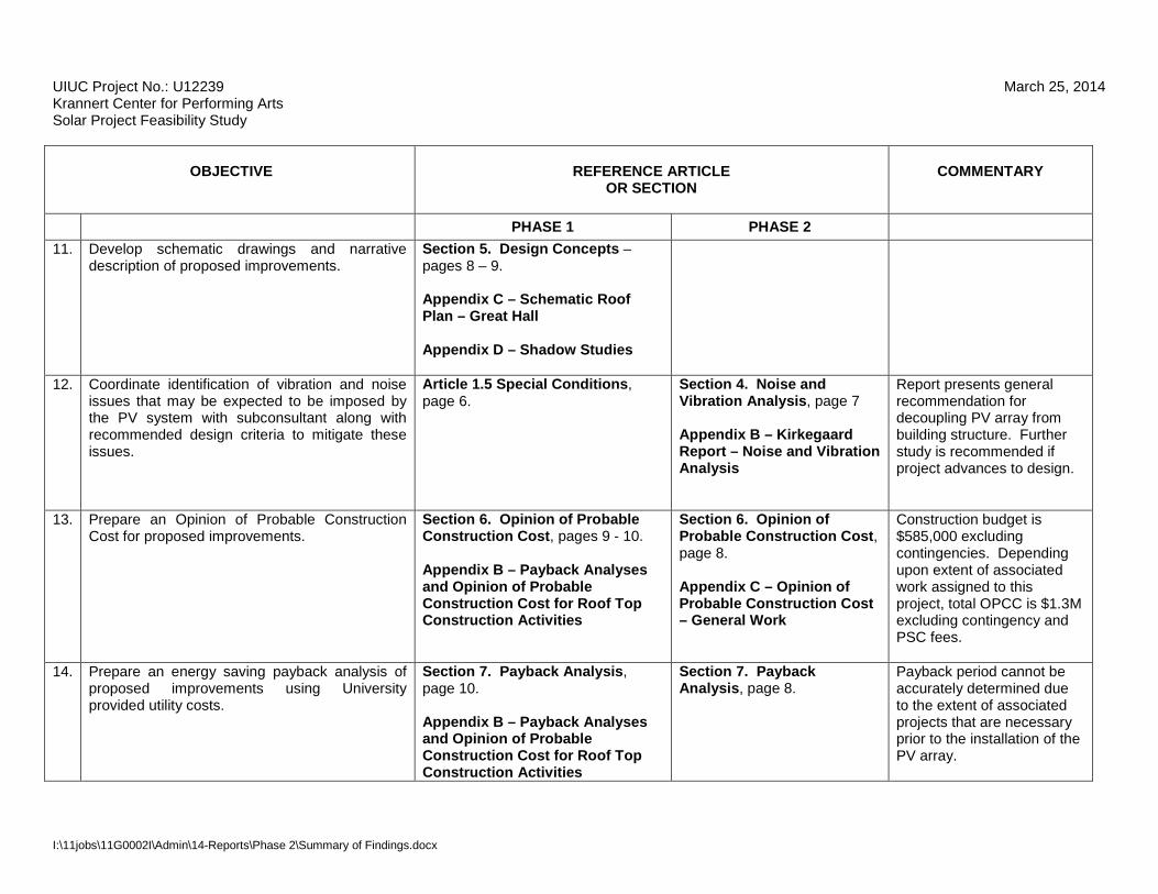
11. Develop schematic drawings and narrative description of proposed improvements.
Section 5. Design Concepts – pages 8 – 9. Appendix C – Schematic Roof Plan – Great Hall Appendix D – Shadow Studies
12. Coordinate identification of vibration and noise issues that may be expected to be imposed by the PV system with subconsultant along with recommended design criteria to mitigate these issues.
Article 1.5 Special Conditions, page 6.
Section 4. Noise and Vibration Analysis, page 7 Appendix B – Kirkegaard Report – Noise and Vibration Analysis
Report presents general recommendation for decoupling PV array from building structure. Further study is recommended if project advances to design.
13. Prepare an Opinion of Probable Construction Cost for proposed improvements.
Section 6. Opinion of Probable Construction Cost, pages 9 - 10. Appendix B – Payback Analyses and Opinion of Probable Construction Cost for Roof Top Construction Activities
Section 6. Opinion of Probable Construction Cost, page 8. Appendix C – Opinion of Probable Construction Cost – General Work
Construction budget is $585,000 excluding contingencies. Depending upon extent of associated work assigned to this project, total OPCC is $1.3M excluding contingency and PSC fees.
14. Prepare an energy saving payback analysis of proposed improvements using University provided utility costs.
Section 7. Payback Analysis, page 10. Appendix B – Payback Analyses and Opinion of Probable Construction Cost for Roof Top Construction Activities
Section 7. Payback Analysis, page 8.
Payback period cannot be accurately determined due to the extent of associated projects that are necessary prior to the installation of the PV array.
I:\11jobs\11G0002I\Admin\14-Reports\Phase 2\Summary of Findings.docx

UIUC Project No.: U12239 March 25, 2014 Krannert Center for Performing Arts Solar Project Feasibility Study
OBJECTIVE
REFERENCE ARTICLE
OR SECTION
COMMENTARY
PHASE 1 PHASE 2
15. Update renderings produced in Phase 1.
Appendix E - Renderings – Line Type for Great Hall at 34° and 10° Inclination of Solar Panels and Overall ground Level Photo Renderings
No change since Phase 1.
16. Evaluate the potential benefits of electrochromic glazing in the west curtain wall of the Great Hall.
Appendix H – Electrochromic Glazing Evaluation for Great Hall
Recapitulation of Opinion of Probable Construction Cost
ITEM Phase 1 OPCC Phase 2 OPCC Roofing Replacement Not included $360,000 Construction Access and General Construction $128,000 $132,000 Roof Scuttle Improvements Not included $15,000 Roof Truss Strengthening Not included $300,000 Noise and Vibration Mitigation Not included $36,000 Electrical conduit / routing $117,000 $117,000 PV cells and Micro-inverters $326,000 $326,000 Electrical Power Distribution Equipment $10,000 $10,000 Kiosk $4,000 $4000 TOTAL (excluding contingencies) $585,000 $1,300,000
I:\11jobs\11G0002I\Admin\14-Reports\Phase 2\Summary of Findings.docx

Engineering | Planning | Allied Services
Krannert Center for the Performing Arts Solar Project Feasibility Study University of Illinois at Urbana-Champaign Project Number: U12239 Phase 1 March 1, 2013 (revised August 29, 2013)
Krannert PV Feasibility Study Phase I University of Illinois at Urbana-Champaign
I:\11jobs\11G0002I\Admin\14-Reports\REP-Feasibility_Study.docx University of Illinois 1
Table of Contents
EXECUTIVE SUMMARY ....................................................................................................................... 3
1. DESCRIPTION, OPTIONS, OBJECTIVES, PROGRAM AND SPECIAL CONDITIONS ................ 4
1.1 Project Description .......................................................................................................................... 4
1.2 Master Plan Impact and Options .................................................................................................... 4
1.3 Major Project Objectives, and Design Requirements ...................................................................... 4
1.4 Program Summary ......................................................................................................................... 5
1.5 Special Conditions ......................................................................................................................... 5
2. CODES AND PERMITS ................................................................................................................. 7
2.1 Applicable Codes and Standards ................................................................................................... 7
2.2 Applicable Permits ......................................................................................................................... 7
3. SITE REQUIREMENTS ................................................................................................................. 7
4. MAINTENANCE BUDGET & ENERGY BUDGET FOR SUSTAINABILITY ................................... 8
5. DESIGN CONCEPTS .................................................................................................................... 8
6. OPINION OF PROBABLE CONSTRUCTION COST ..................................................................... 9
7 PAYBACK ANALYSIS .................................................................................................................. 10
8. PROJECT SCHEDULE ............................................................................................................... 10
9. UIUC REVIEW COMMENTS ........................................................................................................ 10
Krannert PV Feasibility Study Phase I University of Illinois at Urbana-Champaign
I:\11jobs\11G0002I\Admin\14-Reports\REP-Feasibility_Study.docx University of Illinois 2
Appendices Appendix A – Site Plan Appendix B – Payback Analyses and Opinion of Probable Construction Cost for Roof Top Construction
Activities Appendix C – Schematic Roof Plan – Great Hall Appendix D – Shadow Studies Appendix E – Renderings – Line Type for Great Hall at 34° and 10° inclination of Solar Panels and
Overall Ground Level Photo Renderings Appendix F – Conceptual Crane Placement Appendix G – Generic Wiring Diagram, Example of Micro-inverter and Product Data Sheet for Typical
Photovoltaic Panel Appendix H – Electrochromic Glazing Evaluation for Great Hall Appendix I – UIUC Review Comments Copyright 2012 by Hanson Professional Services Inc. All rights reserved. This document is intended solely for the individual or the entity to which it is addressed. The information contained in this document shall not be duplicated, stored electronically, or distributed, in whole or in part, by anyone other than the recipient without the express written permission of Hanson Professional Services Inc., 1525 S. Sixth St., Springfield, IL 62703, (217) 788-2450, www.hanson-inc.com. Unauthorized reproduction or transmission of any part of this document is a violation of federal law. Any concepts, designs and project approaches contained herein are considered proprietary. Any use of these concepts and approaches by others is considered a violation of copyright law.

Krannert PV Feasibility Study Phase I University of Illinois at Urbana-Champaign
I:\11jobs\11G0002I\Admin\14-Reports\REP-Feasibility_Study.docx University of Illinois 3
Executive Summary
The purpose of the study is to examine the feasibility of installing a solar photovoltaic (PV) system on one or more of the roofs at Krannert Center for the Performing Arts (KCPA). The study also addresses the potential use of electrochromic glazing on the west curtain wall of the Great Hall. Phase 1 of the study, presented herein, examines the visual impact on the facility and presents to the University an opinion of probable construction cost (OPCC), general considerations of construction phasing and associated general construction, and a simple payback analysis for the PV array. As part of Phase 1, the space requirements for the PV system’s inverters have been identified along with potential installation location(s) within the KCPA facility. If after considering the findings of Phase 1 of this study the University elects to further evaluate the feasibility of installing a PV array atop one or more of the roofs of the KCPA facilities, this study will continue with a second phase (Phase 2). This second phase will include an evaluation of the structural load the PV system would impose on the facility (gravity and wind), and an assessment of the general condition of the existing roofing material to identify the anticipated remaining useful life of the roofs. A noise and vibration analysis will also be included in Phase 2 to identify the acoustic impact the PV system installation may be expected to have on the performance spaces within the facility. A five hundred eighty-five thousand dollar ($585,000) construction budget, excluding contingencies, has been established for this project. Based on the assessments that have been completed during Phase 1, approximately four hundred fifty-seven thousand dollars ($457,000) would be directed toward the purchase and installation of solar panels and electrical work, with the remaining, one hundred twenty-eight thousand dollars ($128,000), being directed toward the costs of the associated general construction and construction access. This results in a net effective installed cost of between seven dollars and twenty-five cents and seven dollars and fifty cents ($7.25 and $7.50) per Watt. For general consideration, using an offset in consumption of 105,120 Watts / year, and a utility cost of twelve cents ($0.12) / Watt, the estimated payback period is substantially longer than 25 years. The cost of electrochromic glazing at the west curtain wall of the Great Hall is not included in the overall project cost assessment described in the preceding paragraph. It is generally approximated, thought to be on the order of three hundred thousand dollars ($300,000) to three hundred fifty thousand dollars ($350,000). Energy savings resulting from the use of electrochromic glazing are estimated to be under one thousand five hundred dollars ($1,500) annually.
Krannert PV Feasibility Study Phase I University of Illinois at Urbana-Champaign
I:\11jobs\11G0002I\Admin\14-Reports\REP-Feasibility_Study.docx University of Illinois 4
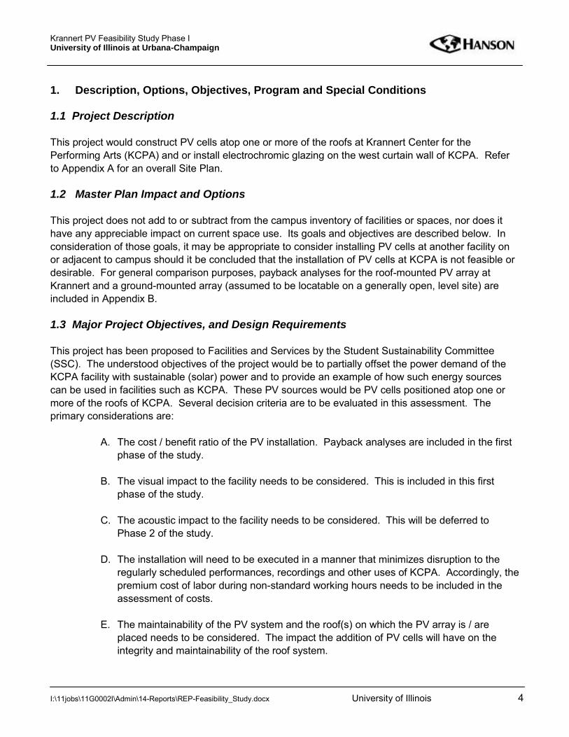
1. Description, Options, Objectives, Program and Special Conditions 1.1 Project Description This project would construct PV cells atop one or more of the roofs at Krannert Center for the Performing Arts (KCPA) and or install electrochromic glazing on the west curtain wall of KCPA. Refer to Appendix A for an overall Site Plan. 1.2 Master Plan Impact and Options This project does not add to or subtract from the campus inventory of facilities or spaces, nor does it have any appreciable impact on current space use. Its goals and objectives are described below. In consideration of those goals, it may be appropriate to consider installing PV cells at another facility on or adjacent to campus should it be concluded that the installation of PV cells at KCPA is not feasible or desirable. For general comparison purposes, payback analyses for the roof-mounted PV array at Krannert and a ground-mounted array (assumed to be locatable on a generally open, level site) are included in Appendix B. 1.3 Major Project Objectives, and Design Requirements This project has been proposed to Facilities and Services by the Student Sustainability Committee (SSC). The understood objectives of the project would be to partially offset the power demand of the KCPA facility with sustainable (solar) power and to provide an example of how such energy sources can be used in facilities such as KCPA. These PV sources would be PV cells positioned atop one or more of the roofs of KCPA. Several decision criteria are to be evaluated in this assessment. The primary considerations are:
A. The cost / benefit ratio of the PV installation. Payback analyses are included in the first phase of the study.
B. The visual impact to the facility needs to be considered. This is included in this first phase of the study.
C. The acoustic impact to the facility needs to be considered. This will be deferred to Phase 2 of the study.
D. The installation will need to be executed in a manner that minimizes disruption to the
regularly scheduled performances, recordings and other uses of KCPA. Accordingly, the premium cost of labor during non-standard working hours needs to be included in the assessment of costs.
E. The maintainability of the PV system and the roof(s) on which the PV array is / are placed needs to be considered. The impact the addition of PV cells will have on the integrity and maintainability of the roof system.

Krannert PV Feasibility Study Phase I University of Illinois at Urbana-Champaign
I:\11jobs\11G0002I\Admin\14-Reports\REP-Feasibility_Study.docx University of Illinois 5
1.4 Program Summary The intended program seeks to derive the benefit of solar energy to offset the building’s power consumption within an overall construction budget of $585,000, excluding bid and construction contingencies. This budget is to be directed toward the PV installation, and does not include the cost of replacement of any other building features, such as roofing, that should otherwise be included as part of the building’s regular maintenance. 1.5 Special Conditions Architectural Layout of the PV cells should maximize exposure to the sun, limit visual impact on the facility and, within the foregoing constraints, facilitate maintenance of the building and the new equipment as much as reasonably practicable. Also, the layout must not obstruct roof access with respect to existing openings. Given these objectives, the roofs of the Great Hall, Drama Theater and Music Theater were initially considered as probable locations for PV arrays. However, the focus of the study was ultimately directed to the roof of the Great Hall. This decision was reached in consideration of maximizing sun exposure (the backstage housing projections at the Drama Theater and Music Theater block the afternoon sun to a much greater extent than the backstage housing projection of the Great Hall blocks the morning sun), and the higher elevation of the Great Hall roof mitigates the visual impact the PV array has on the building. Refer to Appendix C for a “Schematic Roof Plan” of the Great Hall that depicts the PV array. Refer to Appendix C for Shadow Studies. The optimal angle of inclination of the solar panels for the latitude of Champaign, Illinois is considered to be approximately 34°. Line-type renderings showing the projection of the panels at 34 degrees inclination and 10 degrees inclination are included in this report for general comparison of visual impact. Ground level photo renderings are included for the 34° inclination of the PV array. Refer to Appendix E. PV cells generate Direct Current (DC) that needs to be converted to Alternating Current (AC) for efficient distribution and compatibility with building power. The DC current from the panels could be routed to a centralized inverter, located somewhere within the facility, or alternatively, micro-inverters can be included with each of the PV panels, eliminating the interior space need for the central inverter. For purposes of this study, it appears that a central inverter could be located in one of the booths at the rear of the Great Hall if the central inverter configuration is chosen. Roofing Roofs at the Great Hall and theaters are fully adhered EPDM. Facilities and Services has reviewed their records for the roofing of the Great Hall and reported that the roofing of the Great Hall was replaced by King Lar in 1995, and was covered by a 15 year (Firestone) warranty. Roofs of the Drama Theater and Music Theater were replaced in 1998 by Advanced Roofing. These roofs were also reportedly covered by 15 year Firestone warranties.
Krannert PV Feasibility Study Phase I University of Illinois at Urbana-Champaign
I:\11jobs\11G0002I\Admin\14-Reports\REP-Feasibility_Study.docx University of Illinois 6
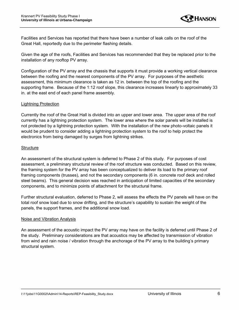
Facilities and Services has reported that there have been a number of leak calls on the roof of the Great Hall, reportedly due to the perimeter flashing details. Given the age of the roofs, Facilities and Services has recommended that they be replaced prior to the installation of any rooftop PV array. Configuration of the PV array and the chassis that supports it must provide a working vertical clearance between the roofing and the nearest components of the PV array. For purposes of the aesthetic assessment, this minimum clearance is taken as 12 in. between the top of the roofing and the supporting frame. Because of the 1:12 roof slope, this clearance increases linearly to approximately 33 in. at the east end of each panel frame assembly. Lightning Protection Currently the roof of the Great Hall is divided into an upper and lower area. The upper area of the roof currently has a lightning protection system. The lower area where the solar panels will be installed is not protected by a lightning protection system. With the installation of the new photo-voltaic panels it would be prudent to consider adding a lightning protection system to the roof to help protect the electronics from being damaged by surges from lightning strikes. Structure An assessment of the structural system is deferred to Phase 2 of this study. For purposes of cost assessment, a preliminary structural review of the roof structure was conducted. Based on this review, the framing system for the PV array has been conceptualized to deliver its load to the primary roof framing components (trusses), and not the secondary components (6 in. concrete roof deck and rolled steel beams). This general decision was reached in anticipation of limited capacities of the secondary components, and to minimize points of attachment for the structural frame. Further structural evaluation, deferred to Phase 2, will assess the effects the PV panels will have on the total roof snow load due to snow drifting, and the structure’s capability to sustain the weight of the panels, the support frames, and the additional snow load. Noise and Vibration Analysis An assessment of the acoustic impact the PV array may have on the facility is deferred until Phase 2 of the study. Preliminary considerations are that acoustics may be affected by transmission of vibration from wind and rain noise / vibration through the anchorage of the PV array to the building’s primary structural system.
Krannert PV Feasibility Study Phase I University of Illinois at Urbana-Champaign
I:\11jobs\11G0002I\Admin\14-Reports\REP-Feasibility_Study.docx University of Illinois 7
2. Codes and Permits 2.1 Applicable Codes and Standards
University of Illinois Facilities and Services Standards for Design and Construction. ASCE 7-05 “Minimum Design Loads for Buildings and Other Structures.” Structural Loadings (gravity and wind) will need to be assessed per the International Building
Code, 2009. Electrical design shall conform to the National Electrical Code (NEC) 2011. Code of Federal Regulations 29 CFR 1910 (pertaining to servicing of equipment near roof
edges). 2012 International Fire Code (pertaining to maintenance of access to existing roof openings).
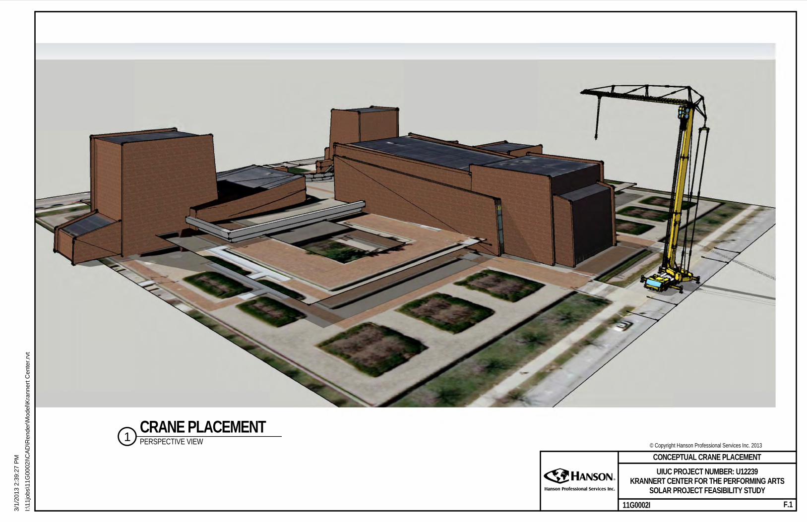
2.2 Applicable Permits Should this project proceed to subsequent phases of investigation and design, configuration of the disconnect will need to be confirmed with the Electric Utility so that in cases of power outages the distribution network would not be back-fed by the PV array, thus energizing lines that would otherwise be thought to be de-energized. An additional protection to the manual disconnect switch is the inverter monitor’s normal power, and if it is lost, the inverter automatically disengages the system’s ability to back-feed power. 3. Site Requirements Construction access for work on the Great Hall is expected to be gained via the east (Gregory Place) side of the facility. Laydown space and routing for deliveries is, at this time, thought to be achievable via the use of the plinth level immediately east of the Great Hall. At times, deliveries of equipment and materials may necessitate limitations on parking and pedestrian access from the Gregory Place side. Such limits (or shutdowns) would need to be coordinated around the scheduled activities at KCPA. It is likely that a crane will be required to hoist components for the frame that will be constructed atop the roof to support the PV array. None of these components is expected to be extremely heavy (maybe on the order of 700 pounds for an individual steel beam, if it is concluded that the frame will indeed be steel-framed), but due to the required reach of the crane, a 165 ton all terrain crane is expected to be necessary for material hoisting. Refer to Appendix F for “Conceptual Crane Placement.” Regular construction phase access for workmen and lighter material components and personnel to the roof of the Great Hall might be accomplished via a temporary construction stairway that could be installed somewhere along the east façade of the Great Hall. The benefits to the project of installing such a stairway are reduced travel time for the workmen to the roof, and a reduction of interruptions to the occupants of the facility. This project is not expected to require any demolition, abandonments or relocations of utilities.

Krannert PV Feasibility Study Phase I University of Illinois at Urbana-Champaign
I:\11jobs\11G0002I\Admin\14-Reports\REP-Feasibility_Study.docx University of Illinois 8
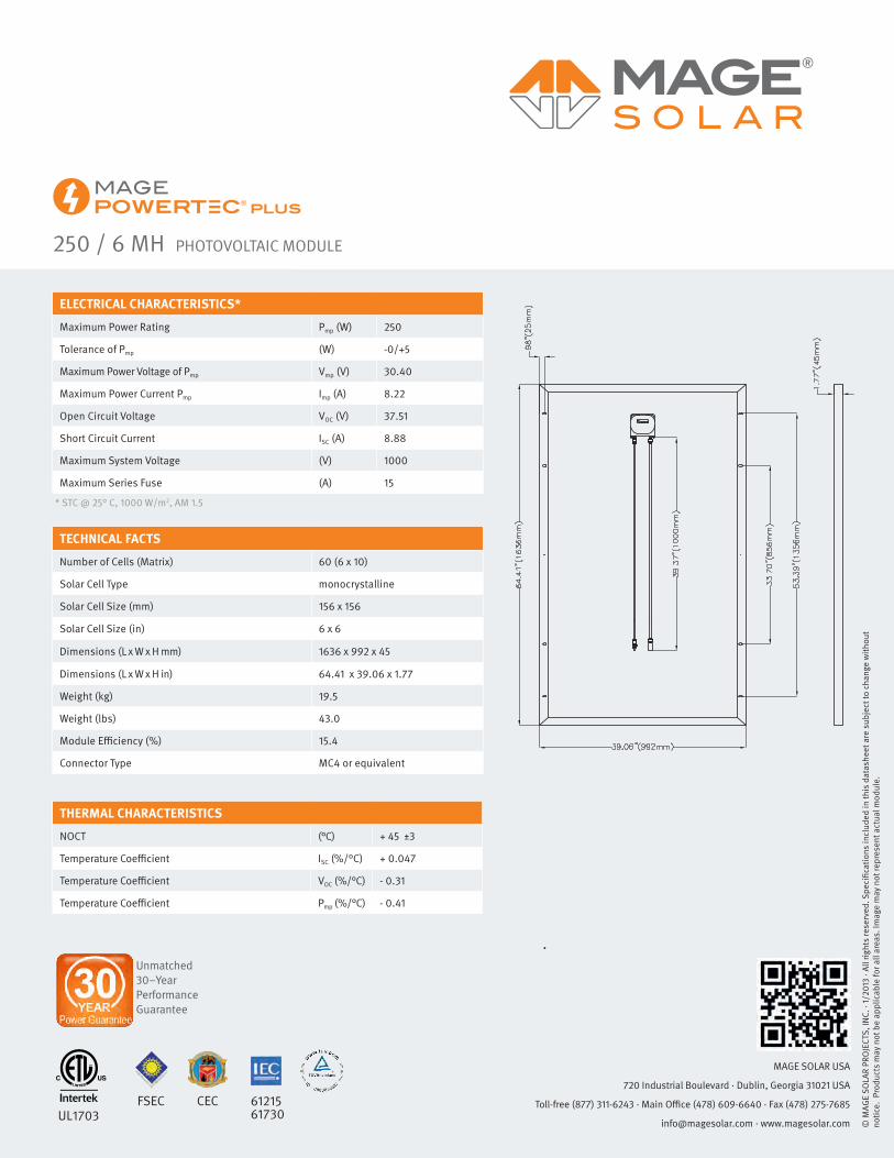
It is thought that the impacts of construction noise (crane engines, hammer drilling, concrete coring) on the functionality of the facility can be satisfactorily addressed by minimizing (or even prohibiting) such activities during performances and recordings. To achieve this objective, the contractor and KCPA administrators will need to agree to a work schedule, the general constraints of which should be defined in the bidding documents. For purposes of this study, some work activities are considered as being required to take place during non-standard working hours, and a 50 percent labor rate premium is included. 4. Maintenance Budget & Energy Budget for Sustainability The PV array should require only minimal maintenance, and should have a service life of 20 to 25 years. This project should not result in an increase in the overall campus energy budget. On the contrary, this project should result in a reduction in the energy budget, as described within this report. 5. Design Concepts Roof-mounted PV Array A field investigation was conducted on Friday February 15, 2013. The focus of the investigation was to determine a suitable location for the electronics and panel-boards required for a new PV system and to observe the main electrical service room serving the Great Hall. The current focus is to limit the location of new PV panels to the roof of the Great Hall only. Several factors went in to making this decision. From the perspective of electrical efficiency, a significant consideration is limiting, to the extent practicable, the number of three phase AC feeders that will need to be routed from the roof level of the building down to the lower level and connected into the main AC distribution system for the building. Currently the building’s electrical power is served from four different locations. The existing service consists of primary metering and primary cabling routed underneath the building to four separate unit substations. Focusing on the Great Hall is considered to provide the maximum amount of solar generation, within the project budget, while minimizing dollars on other associated construction, such as running additional conduits and wiring. Consideration has been given to the many types of inverter technologies for solar systems including; central inverter systems, string inverters and micro-inverters. Based on the limited amount of physical space near the roof level of the building and the difficulty in getting larger equipment to the upper level of the Great Hall, micro-inverters are recommended as a reasonable approach to this particular installation. A micro-inverter would be located at each photo-voltaic panel and the voltage is converted to AC right at the panel. The AC power will then be connected to a new power distribution panel in the upper level of the Krannert facility. The panel will then be tied back into the building main distribution system allowing power from the photo-voltaic array to be utilized to offset the building’s electricity consumption. Based on the project budget and preliminary evaluation, it has been preliminarily conceptualized that an 80 KW photo-voltaic system should be constructible on the facility. This is expected to consist of 320, 250-watt photo-voltaic panels. It is expected that the panels would fit on the lower portion of the roof of

Krannert PV Feasibility Study Phase I University of Illinois at Urbana-Champaign
I:\11jobs\11G0002I\Admin\14-Reports\REP-Feasibility_Study.docx University of Illinois 9
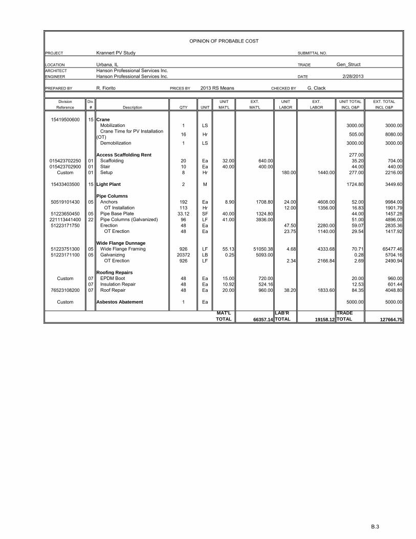
the Great Hall as can be seen in the “Schematic Roof Plan – Great Hall” (Appendix C). A new 208Y/120VAC three phase 400A panel will need to be installed on the upper level of the Krannert facility in one of the existing rooms. A new feeder will then be routed down to the lower level of the building and tie into an existing main distribution panelboard. It is thought that the chase located near the southwest corner of the Great Hall can be used for cable rating. A network communications cable will need to be installed to the location of the new panel at the upper level of the facility. A communications gateway then can be installed to monitor the specific energy generation of the system. This information can then be transported over the facility’s IP network and be displayed at a computer or Kiosk for convenient monitoring. A basic non-project specific wiring diagram, example of a micro-inverter and a product data sheet for a typical solar panel are included in Appendix G. Roof Access for Maintenance of the PV Array Periodic access (every six to nine months) for maintenance of the PV array should be expected. This access would be facilitated if ladder and scuttle layout that accesses the west end of the roof of the Great Hall were reconfigured to allow a single ladder run from the Booth floor level to the roof. In its current configuration, personnel who access the roof of the Great Hall from the Booth level first pass through an opening in the ceiling. From just above the ceiling, they must then pass through a portal type opening to another floor from which a second ladder leads to the roof. This passageway is cumbersome and consideration should be given to improving it. It appears that shifting the roof hatch 3 to 4 ft to the south would provide for this direct access. This alternate location is shown on the conceptual roof plan layout of the PV array. The cost for this improvement is not included in the evaluation for this project, as it may be more appropriate to include this work with the separate roofing replacement project that would precede the PV installation 6. Opinion of Probable Construction Cost The opinion of probable construction cost for the roof-mounted PV system, considering the difficulty level of the installation, is between seven dollars and twenty-five cents and seven dollars and fifty cents ($7.25-$7.50) per Watt. For an 80 KW (or 80,000 Watt) system the opinion of installed cost for the photo-voltaic system is summarized as follows:
Roofing Replacement NOT IN PROJECT Access and General Construction $128,000 Roof Scuttle improvements NOT IN PROJECT Electrical conduit / routing $117,000 PV cells and Micro-inverters $326,000 Electrical Power Distribution Equipment $10,000 Kiosk $4,000 TOTAL (excluding contingencies) $585,000

Krannert PV Feasibility Study Phase I University of Illinois at Urbana-Champaign
I:\11jobs\11G0002I\Admin\14-Reports\REP-Feasibility_Study.docx University of Illinois 10
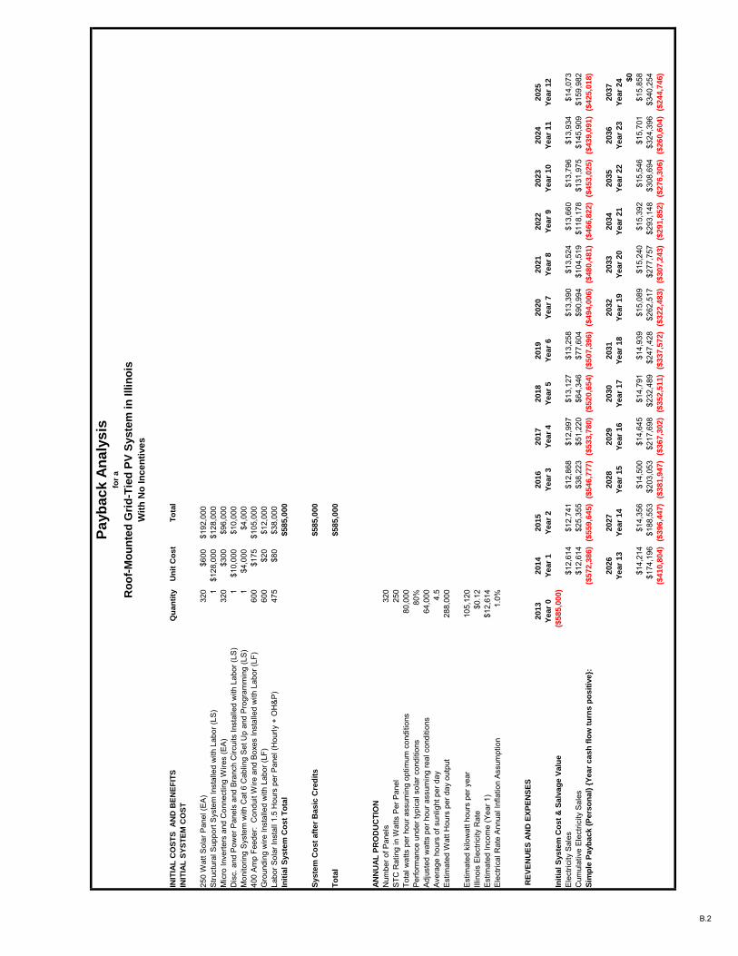
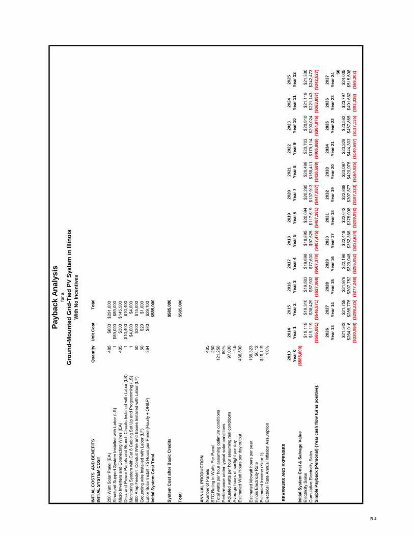
An allowance for shifting the roof scuttle to allow a single ladder run from the Booth level to the roof is not included in the Opinion of Probable Construction Cost (OPCC), but it is recommended that such an improvement be made to facilitate access to the roof. It is recommended that the project be bid with alternates. For example the Base Bid could include a 60 KW system and there could be an alternate additive per unit bid for additional 10KW blocks. Grants may be available to partially offset construction cost; however, identifying such grants is not within the scope of this study. 7 Payback Analysis The payback analysis is included in Appendix B of this report. The analysis shows an estimated annual payback of around twelve thousand six hundred dollars ($12,600) from energy savings on the five hundred eighty-five thousand dollar ($585,000) initial investment for the roof-mounted PV array. No attempt has been made to assign a dollar value to the benefits of environmental stewardship. For comparison purposes, a ground-mounted PV array may be expected to have an annual payback of nineteen thousand dollars ($19,000) on the same five hundred eighty-five thousand dollar ($585,000) initial investment. 8. Project Schedule A tentative project schedule will be identified during Phase 2 of the study. At this time, it is thought that on-site construction duration would be no more than eight weeks, assuming a construction schedule that would allow a 40 hour work week, of reasonable blocks of time. It is recognized that such working blocks of time may be limited to early morning, or night-time hours. 9. UIUC Review Comments Refer to Appendix I.

Appendix A Site Plan

© Copyright Hanson Professional Services Inc. 2013
11G0002II:\11
jobs
\11G
0002
I\CA
D\R
ende
r\Mod
el\K
rann
ert C
ente
r.rvt
3/1/
2013
10:
34:0
5 A
M SITE PLAN
A.1
UIUC PROJECT NUMBER: U12239KRANNERT CENTER FOR THE PERFORMING ARTS
SOLAR PROJECT FEASIBILITY STUDY
NO SCALE:1SITE PLAN

Appendix B Payback Analyses and
Opinion of Probable Construction Cost for Roof Top Construction Activities

B.1
PAYBACK ANALYSES
AND
OPINION OF PROBABLE CONSTRUCTION COST
The Payback Analyses and Opinion of Probable Construction Cost (OPCC) prepared by Hanson Professional Services Inc. (Hanson) represent our best judgment as design professionals familiar with the construction industry. It should be recognized, however, that Hanson has no control over the cost of labor, materials or equipment, over the Contractor’s methods of determining bid prices, over competitive bidding or market conditions, or over escalation in costs subsequent from the date of preparing these analyses and opinions of cost. Accordingly, Hanson cannot and does not guarantee that bids and actual payback will not vary from the opinions expressed herein.
The OPCC is based on Means 2013, first quarter for the Champaign-Urban area.
INIT
IAL
CO
ST
S A
ND
BE
NE
FIT
SQ
uan
tity
Un
it C
os
tT
ota
l
INIT
IAL
SY
ST
EM
CO
ST
250
Wat
t Sol
ar P
anel
(EA
)32
0$6
00$1
92,0
00S
truct
ural
Sup
port
Sys
tem
Inst
alle
d w
ith L
abor
(LS
)1
$128
,000
$128
,000
Mic
ro In
verte
rs a
nd C
onne
ctin
g W
ires
(EA
)32
0$3
00$9
6,00
0D
isc.
and
Pow
er P
anel
s an
d B
ranc
h C
ircui
ts In
stal
led
with
Lab
or (L
S)
1$1
0,00
0$1
0,00
0M
onito
ring
Sys
tem
with
Cat
6 C
ablin
g S
et U
p an
d P
rogr
amm
ing
(LS
)1
$4,0
00$4
,000
400
Am
p Fe
eder
: C
ondu
it W
ire a
nd B
oxes
Inst
alle
d w
ith L
abor
(LF)
600
$175
$105
,000
Gro
undi
ng w
ire In
stal
led
with
Lab
or (L
F)60
0$2
0$1
2,00
0La
bor S
olar
Inst
all 1
.5 H
ours
per
Pan
el (H
ourly
+ O
H&
P)
475
$80
$38,
000
Init
ial S
yste
m C
ost
To
tal
$585,0
00
Syste
m C
ost
aft
er
Basic
Cre
dit
s$585,0
00
To
tal
$585,0
00
AN
NU
AL
PR
OD
UC
TIO
N
Num
ber o
f Pan
els
320
STC
Rat
ing
in W
atts
Per
Pan
el25
0To
tal w
atts
per
hou
r ass
umin
g op
timum
con
ditio
ns80
,000
Per
form
ance
und
er ty
pica
l sol
ar c
ondi
tions
80%
Adj
uste
d w
atts
per
hou
r ass
umin
g re
al c
ondi
tions
64,0
00A
vera
ge h
ours
of s
unlig
ht p
er d
ay4.
5E
stim
ated
Wat
t Hou
rs p
er d
ay o
utpu
t28
8,00
0
Est
imat
ed k
ilow
att h
ours
per
yea
r10
5,12
0Ill
inoi
s E
lect
ricity
Rat
e$0
.12
Est
imat
ed In
com
e (Y
ear 1
)$1
2,61
4E
lect
rical
Rat
e A
nnua
l Inf
latio
n A
ssum
ptio
n1.
0%
RE
VE
NU
ES
AN
D E
XP
EN
SE
S
2013
2014
2015
2016
2017
2018
2019
2020
2021
2022
2023
2024
2025
Year
0Y
ear
1Y
ear
2Y
ear
3Y
ear
4Y
ear
5Y
ear
6Y
ear
7Y
ear
8Y
ear
9Y
ear
10
Year
11
Year
12
Init
ial S
yste
m C
ost
& S
alv
ag
e V
alu
e($
58
5,0
00
)
Ele
ctric
ity S
ales
$12,
614
$12,
741
$12,
868
$12,
997
$13,
127
$13,
258
$13,
390
$13,
524
$13,
660
$13,
796
$13,
934
$14,
073
Cum
ulat
ive
Ele
ctric
ity S
ales
$12,
614
$25,
355
$38,
223
$51,
220
$64,
346
$77,
604
$90,
994
$104
,519
$118
,178
$131
,975
$145
,909
$159
,982
Sim
ple
Payb
ack (
Pers
on
al)
{Y
ear
cash
flo
w t
urn
s p
osit
ive}:
($5
72,3
86
)($
55
9,6
45
)($
54
6,7
77
)($
53
3,7
80
)($
52
0,6
54
)($
50
7,3
96
)($
49
4,0
06
)($
48
0,4
81
)($
46
6,8
22
)($
45
3,0
25
)($
43
9,0
91
)($
42
5,0
18
)
2026
2027
2028
2029
2030
2031
2032
2033
2034
2035
2036
2037
Year
13
Year
14
Year
15
Year
16
Year
17
Year
18
Year
19
Year
20
Year
21
Year
22
Year
23
Year
24 $
0
$14,
214
$14,
356
$14,
500
$14,
645
$14,
791
$14,
939
$15,
089
$15,
240
$15,
392
$15,
546
$15,
701
$15,
858
$174
,196
$188
,553
$203
,053
$217
,698
$232
,489
$247
,428
$262
,517
$277
,757
$293
,148
$308
,694
$324
,396
$340
,254
($4
10,8
04
)($
39
6,4
47
)($
38
1,9
47
)($
36
7,3
02
)($
35
2,5
11
)($
33
7,5
72
)($
32
2,4
83
)($
30
7,2
43
)($
29
1,8
52
)($
27
6,3
06
)($
26
0,6
04
)($
24
4,7
46
)
B.2
Pa
yb
ac
k A
na
lys
isfo
r a
Ro
of-
Mo
un
ted
Gri
d-T
ied
PV
Syste
m in
Illin
ois
Wit
h N
o In
cen
tives
OPINION OF PROBABLE COST
PROJECT Krannert PV Study SUBMITTAL NO.
LOCATION Urbana, IL TRADE Gen_StructARCHITECT Hanson Professional Services Inc.ENGINEER Hanson Professional Services Inc. DATE 2/28/2013
PREPARED BY R. Fiorito PRICES BY 2013 RS Means CHECKED BY G. Clack
Division Div. UNIT EXT. UNIT EXT. UNIT TOTAL EXT. TOTALReference # Description QTY UNIT MAT'L MAT'L LABOR LABOR INCL O&P INCL O&P
15419500600 15 Crane
Mobilization 1 LS 3000.00 3000.00 Crane Time for PV Installation (OT) 16 Hr 505.00 8080.00
Demobilization 1 LS 3000.00 3000.00
Access Scaffolding Rent 277.00015423702250 01 Scaffolding 20 Ea 32.00 640.00 35.20 704.00015423702900 01 Stair 10 Ea 40.00 400.00 44.00 440.00
Custom 01 Setup 8 Hr 180.00 1440.00 277.00 2216.00
15433403500 15 Light Plant 2 M 1724.80 3449.60
Pipe Columns
50519101430 05 Anchors 192 Ea 8.90 1708.80 24.00 4608.00 52.00 9984.00 OT Installation 113 Hr 12.00 1356.00 16.83 1901.79
51223650450 05 Pipe Base Plate 33.12 SF 40.00 1324.80 44.00 1457.28221113441400 22 Pipe Columns (Galvanized) 96 LF 41.00 3936.00 51.00 4896.0051223171750 Erection 48 Ea 47.50 2280.00 59.07 2835.36
OT Erection 48 Ea 23.75 1140.00 29.54 1417.92
Wide Flange Dunnage
51223751300 05 Wide Flange Framing 926 LF 55.13 51050.38 4.68 4333.68 70.71 65477.4651223171100 05 Galvanizing 20372 LB 0.25 5093.00 0.28 5704.16
OT Erection 926 LF 2.34 2166.84 2.69 2490.94
Roofing Repairs
Custom 07 EPDM Boot 48 Ea 15.00 720.00 20.00 960.0007 Insulation Repair 48 Ea 10.92 524.16 12.53 601.44
76523108200 07 Roof Repair 48 Ea 20.00 960.00 38.20 1833.60 84.35 4048.80
Custom Asbestos Abatement 1 Ea 5000.00 5000.00
MAT'L
TOTAL 66357.14
LAB'R
TOTAL 19158.12
TRADE
TOTAL 127664.75
B.3
INIT
IAL
CO
ST
S A
ND
BE
NE
FIT
SQ
ua
nti
tyU
nit
Co
st
To
tal
INIT
IAL
SY
ST
EM
CO
ST
250
Wat
t Sol
ar P
anel
(EA
)48
5$6
00$2
91,0
00S
truct
ural
Sup
port
Sys
tem
Inst
alle
d w
ith L
abor
(LS
)1
$89,
000
$89,
000
Mic
ro In
verte
rs a
nd C
onne
ctin
g W
ires
(EA
)48
5$3
00$1
45,5
00D
isc.
and
Pow
er P
anel
s an
d B
ranc
h C
ircui
ts In
stal
led
with
Lab
or (L
S)
1$1
0,40
0$1
0,40
0M
onito
ring
Sys
tem
with
Cat
6 C
ablin
g S
et U
p an
d P
rogr
amm
ing
(LS
)1
$4,0
00$4
,000
800
Am
p Fe
eder
: C
ondu
it W
ire a
nd B
oxes
Inst
alle
d w
ith L
abor
(LF)
50$3
00$1
5,00
0G
roun
ding
wire
Inst
alle
d w
ith L
abor
(LF)
50$2
0$1
,000
Labo
r Sol
ar In
stal
l .75
Hou
rs p
er P
anel
(Hou
rly +
OH
&P
)36
4$8
0$2
9,10
0In
itia
l S
ys
tem
Co
st
To
tal
$5
85
,00
0
Sy
ste
m C
os
t a
fte
r B
as
ic C
red
its
$5
85
,00
0
To
tal
$5
85
,00
0
AN
NU
AL
PR
OD
UC
TIO
N
Num
ber o
f Pan
els
485
STC
Rat
ing
in W
atts
Per
Pan
el25
0To
tal w
atts
per
hou
r ass
umin
g op
timum
con
ditio
ns12
1,25
0P
erfo
rman
ce u
nder
typi
cal s
olar
con
ditio
ns80
%A
djus
ted
wat
ts p
er h
our a
ssum
ing
real
con
ditio
ns97
,000
Ave
rage
hou
rs o
f sun
light
per
day
4.5
Est
imat
ed W
att H
ours
per
day
out
put
436,
500
Est
imat
ed k
ilow
att h
ours
per
yea
r15
9,32
3Ill
inoi
s E
lect
ricity
Rat
e$0
.12
Est
imat
ed In
com
e (Y
ear 1
)$1
9,11
9E
lect
rical
Rat
e A
nnua
l Inf
latio
n A
ssum
ptio
n1.
0%
RE
VE
NU
ES
AN
D E
XP
EN
SE
S
20
13
20
14
20
15
20
16
20
17
20
18
20
19
20
20
20
21
20
22
20
23
20
24
20
25
Ye
ar
0Y
ea
r 1
Ye
ar
2Y
ea
r 3
Ye
ar
4Y
ea
r 5
Ye
ar
6Y
ea
r 7
Ye
ar
8Y
ea
r 9
Ye
ar
10
Ye
ar
11
Ye
ar
12
Init
ial S
ys
tem
Co
st
& S
alv
ag
e V
alu
e($
58
5,0
00
)
Ele
ctric
ity S
ales
$19,
119
$19,
310
$19,
503
$19,
698
$19,
895
$20,
094
$20,
295
$20,
498
$20,
703
$20,
910
$21,
119
$21,
330
Cum
ulat
ive
Ele
ctric
ity S
ales
$19,
119
$38,
429
$57,
932
$77,
630
$97,
525
$117
,619
$137
,913
$158
,411
$179
,114
$200
,024
$221
,143
$242
,473
Sim
ple
Pa
yb
ac
k (
Pe
rso
na
l) {
Ye
ar
ca
sh
flo
w t
urn
s p
os
itiv
e}:
($5
65
,88
1)
($5
46
,57
1)
($5
27
,06
8)
($5
07
,37
0)
($4
87
,47
5)
($4
67
,38
1)
($4
47
,08
7)
($4
26
,58
9)
($4
05
,88
6)
($3
84
,97
6)
($3
63
,85
7)
($3
42
,52
7)
20
26
20
27
20
28
20
29
20
30
20
31
20
32
20
33
20
34
20
35
20
36
20
37
Ye
ar
13
Ye
ar
14
Ye
ar
15
Ye
ar
16
Ye
ar
17
Ye
ar
18
Ye
ar
19
Ye
ar
20
Ye
ar
21
Ye
ar
22
Ye
ar
23
Ye
ar
24 $
0
$21,
543
$21,
759
$21,
976
$22,
196
$22,
418
$22,
642
$22,
869
$23,
097
$23,
328
$23,
562
$23,
797
$24,
035
$264
,016
$285
,775
$307
,752
$329
,948
$352
,366
$375
,008
$397
,877
$420
,975
$444
,303
$467
,865
$491
,662
$515
,698
($3
20
,98
4)
($2
99
,22
5)
($2
77
,24
8)
($2
55
,05
2)
($2
32
,63
4)
($2
09
,99
2)
($1
87
,12
3)
($1
64
,02
5)
($1
40
,69
7)
($1
17
,13
5)
($9
3,3
38
)($
69
,30
2)
B.4
Payb
ac
k A
na
lys
isfo
r a
Gro
un
d-M
ou
nte
d G
rid
-Tie
d P
V S
ys
tem
in
Illin
ois
Wit
h N
o In
cen
tives

Appendix C Schematic Roof Plan – Great Hall

G36 G11 G12 G13 G14 G15 G16 G17 G18 G19 G20
BACKSTAGE ROOFPROJECTION
6'-0
"
ROOF SCUTTLEAND VENT
PARAPET
PARAPET
NO PARAPET
6'-0
"6'
-0"
6'-0
"
PV PANELS
PV PANELS
AP
PRO
X. 8
2'-0
"
APPROX. 161'-0"
© Copyright Hanson Professional Services Inc. 2013
11G0002II:\11
jobs
\11G
0002
I\CA
D\R
ende
r\Mod
el\K
rann
ert C
ente
r.rvt
3/1/
2013
10:
35:0
6 A
M SCHEMATIC ROOF PLAN - GREAT HALL
C.1
UIUC PROJECT NUMBER: U12239KRANNERT CENTER FOR THE PERFORMING ARTS
SOLAR PROJECT FEASIBILITY STUDY
NORTH
SCALE: 1/16" = 1'-0"1ROOF PLAN

Appendix D Shadow Studies
© Copyright Hanson Professional Services Inc. 2013
11G0002II:\11
jobs
\11G
0002
I\CA
D\R
ende
r\Mod
el\K
rann
ert C
ente
r.rvt
3/1/
2013
10:
36:1
3 A
M SHADOW STUDY - JUNE 21, 10 AM
D.1
UIUC PROJECT NUMBER: U12239KRANNERT CENTER FOR THE PERFORMING ARTS
SOLAR PROJECT FEASIBILITY STUDY
PERSPECTIVE VIEW1SHADOW STUDY - JUNE 21, 2013; 10:00 AM

© Copyright Hanson Professional Services Inc. 2013
11G0002II:\11
jobs
\11G
0002
I\CA
D\R
ende
r\Mod
el\K
rann
ert C
ente
r.rvt
3/1/
2013
10:
37:5
3 A
M SHADOW STUDY - JUNE 21, 4 PM
D.2
UIUC PROJECT NUMBER: U12239KRANNERT CENTER FOR THE PERFORMING ARTS
SOLAR PROJECT FEASIBILITY STUDY
PERSPECTIVE VIEW1SHADOW STUDY - JUNE 21, 2013; 4:00 PM
© Copyright Hanson Professional Services Inc. 2013
11G0002II:\11
jobs
\11G
0002
I\CA
D\R
ende
r\Mod
el\K
rann
ert C
ente
r.rvt
3/1/
2013
10:
39:1
3 A
M SHADOW STUDY - DECEMBER 21, 10 AM
D.3
UIUC PROJECT NUMBER: U12239KRANNERT CENTER FOR THE PERFORMING ARTS
SOLAR PROJECT FEASIBILITY STUDY
PERSPECTIVE VIEW1SHADOW STUDY - DECEMBER 21, 2013; 10:00 AM

© Copyright Hanson Professional Services Inc. 2013
11G0002II:\11
jobs
\11G
0002
I\CA
D\R
ende
r\Mod
el\K
rann
ert C
ente
r.rvt
3/1/
2013
10:
40:2
4 A
M SHADOW STUDY - DECEMBER 21, 4 PM
D.4
UIUC PROJECT NUMBER: U12239KRANNERT CENTER FOR THE PERFORMING ARTS
SOLAR PROJECT FEASIBILITY STUDY
PERSPECTIVE VIEW1SHADOW STUDY - DECEMBER 21, 2013; 4:00 PM

Appendix E Renderings – Line Type for Great Hall at
34° and 10° Inclination of Solar Panels and Overall Ground Level Photo Renderings

© Copyright Hanson Professional Services Inc. 2013
11G0002II:\11
jobs
\11G
0002
I\CA
D\R
ende
r\Mod
el\K
rann
ert C
ente
r.rvt
3/1/
2013
1:0
5:00
PM PERSPECTIVE FROM NORTH - 34º INCLINATION
E.1
UIUC PROJECT NUMBER: U12239KRANNERT CENTER FOR THE PERFORMING ARTS
SOLAR PROJECT FEASIBILITY STUDY
PERSPECTIVE VIEW1NORTH CAMERA - 34º INCLINATION OF SOLAR PANELSPERSPECTIVE VIEW - GREAT HALL ONLY FROM ILLINOIS STREET, LOOKING SOUTH

© Copyright Hanson Professional Services Inc. 2013
11G0002II:\11
jobs
\11G
0002
I\CA
D\R
ende
r\Mod
el\K
rann
ert C
ente
r.rvt
3/1/
2013
1:0
7:46
PM PERSPECTIVE FROM SOUTH - 34º INCLINATION
E.2
UIUC PROJECT NUMBER: U12239KRANNERT CENTER FOR THE PERFORMING ARTS
SOLAR PROJECT FEASIBILITY STUDY
PERSPECTIVE VIEW1SOUTH CAMERA -34º INCLINATION OF SOLAR PANELSPERSPECTIVE VIEW - GREAT HALL ONLY FROM OREGON STREET, LOOKING NORTH

© Copyright Hanson Professional Services Inc. 2013
11G0002II:\11
jobs
\11G
0002
I\CA
D\R
ende
r\Mod
el\K
rann
ert C
ente
r.rvt
3/1/
2013
1:2
9:28
PM PERSPECTIVE FROM WEST - 34º INCLINATION
E.3
UIUC PROJECT NUMBER: U12239KRANNERT CENTER FOR THE PERFORMING ARTS
SOLAR PROJECT FEASIBILITY STUDY
PERSPECTIVE VIEW1EAST CAMERA - 34º INCLINATION OF SOLAR PANELSPERSPECTIVE VIEW - GREAT HALL ONLY FROM 400 FT EAST OF GREGORY PLACE, LOOKING WEST

© Copyright Hanson Professional Services Inc. 2013
11G0002II:\11
jobs
\11G
0002
I\CA
D\R
ende
r\Mod
el\K
rann
ert C
ente
r.rvt
3/1/
2013
1:2
3:54
PM PERSPECTIVE FROM NORTH - 10º INCLINATION
E.4
UIUC PROJECT NUMBER: U12239KRANNERT CENTER FOR THE PERFORMING ARTS
SOLAR PROJECT FEASIBILITY STUDY
SCALE:1NORTH CAMERA - 10º INCLINATION OF SOLAR PANELSPERSPECTIVE VIEW - GREAT HALL ONLY FROM ILLINOIS STREET, LOOKING SOUTH
© Copyright Hanson Professional Services Inc. 2013
11G0002II:\11
jobs
\11G
0002
I\CA
D\R
ende
r\Mod
el\K
rann
ert C
ente
r.rvt
3/1/
2013
1:2
7:44
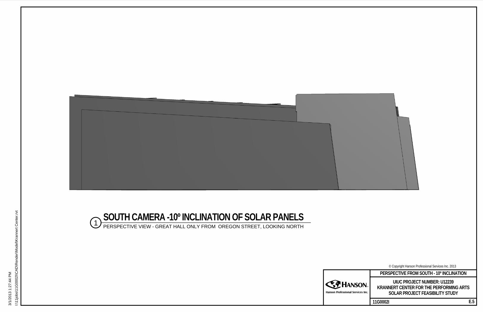
PM PERSPECTIVE FROM SOUTH - 10º INCLINATION
E.5
UIUC PROJECT NUMBER: U12239KRANNERT CENTER FOR THE PERFORMING ARTS
SOLAR PROJECT FEASIBILITY STUDY
SCALE:1SOUTH CAMERA -10º INCLINATION OF SOLAR PANELSPERSPECTIVE VIEW - GREAT HALL ONLY FROM OREGON STREET, LOOKING NORTH
© Copyright Hanson Professional Services Inc. 2013
11G0002II:\11
jobs
\11G
0002
I\CA
D\R
ende
r\Mod
el\K
rann
ert C
ente
r.rvt
3/1/
2013
1:3
1:57
PM PERSPECTIVE FROM WEST- 10º INCLINATION
E.6
UIUC PROJECT NUMBER: U12239KRANNERT CENTER FOR THE PERFORMING ARTS
SOLAR PROJECT FEASIBILITY STUDY
SCALE:1EAST CAMERA - 10º INCLINATION OF SOLAR PANELSPERSPECTIVE VIEW - GREAT HALL ONLY FROM 400 FT EAST OF GREGORY PLACE, LOOKING WEST

© Copyright Hanson Professional Services Inc. 2013
11G0002II:\11
jobs
\11G
0002
I\CA
D\R
ende
r\Mod
el\K
rann
ert C
ente
r.rvt
3/1/
2013
5:0
7:59
PM RENDERING FROM NORTH - 34º INCLINATION
E.7
UIUC PROJECT NUMBER: U12239KRANNERT CENTER FOR THE PERFORMING ARTS
SOLAR PROJECT FEASIBILITY STUDY
NO SCALE:1NORTH RENDERING 34º INCLINATION OF SOLAR PANELS

© Copyright Hanson Professional Services Inc. 2013
11G0002II:\11
jobs
\11G
0002
I\CA
D\R
ende
r\Mod
el\K
rann
ert C
ente
r.rvt
3/1/
2013
5:0
8:31
PM RENDERING FROM WEST - 34º INCLINATION
E.8
UIUC PROJECT NUMBER: U12239KRANNERT CENTER FOR THE PERFORMING ARTS
SOLAR PROJECT FEASIBILITY STUDY
NO SCALE:1WEST RENDERING 34º INCLINATION OF SOLAR PANELS

© Copyright Hanson Professional Services Inc. 2013
11G0002II:\11
jobs
\11G
0002
I\CA
D\R
ende
r\Mod
el\K
rann
ert C
ente
r.rvt
3/1/
2013
4:4
7:09
PM RENDERING FROM EAST - 34º INCLINATION
E.9
UIUC PROJECT NUMBER: U12239KRANNERT CENTER FOR THE PERFORMING ARTS
SOLAR PROJECT FEASIBILITY STUDY
NO SCALE:1EAST RENDERING 34º INCLINATION OF SOLAR PANELS

Appendix F Conceptual Crane Placement
© Copyright Hanson Professional Services Inc. 2013
11G0002II:\11
jobs
\11G
0002
I\CA
D\R
ende
r\Mod
el\K
rann
ert C
ente
r.rvt
3/1/
2013
2:3
9:27
PM CONCEPTUAL CRANE PLACEMENT
F.1
UIUC PROJECT NUMBER: U12239KRANNERT CENTER FOR THE PERFORMING ARTS
SOLAR PROJECT FEASIBILITY STUDY
PERSPECTIVE VIEW1CRANE PLACEMENT

Appendix G Generic Wiring Diagram, Example of
Micro-inverter and Product Data Sheet for Typical Photovoltaic Panel

D
C
B
A
B
A
1345678
12345678
D
C
FIELD WIRING DIAGRAM208 VAC THREE PHASE
IMPORTANT: Make sure to measure the line-to-line and the line-to-neutral voltage of all service entrance conductors prior to installing any solar equipment. The voltages for the 208 Vac rated microinverters should be within the following ranges: line to line - 183 to 229 Vac, line to neutral - 106 to 132 Vac.
JUNCTION BOX
UP TO 25 M215sPER AC BRANCH CIRCUIT
NEUTRAL GROUND
AC DISTRIBUTION PANELOR SUBPANEL
ONE 3- POLE 20 AMPCIRCUIT BREAKER
PER BRANCH CIRCUIT
METER
ENVOY COMMUNICATIONS GATEWAYETHERNET CONNECTIONTO BROADBAND ROUTER
TO METEROR AC DISTRIBUTION
PANEL
PHASE A-B PHASE C-A PHASE B-C
120 Vac POWER CABLE
ENGAGE CABLEBLACK - L1
RED - L2BLUE - L3
WHITE - NEUTRALGREEN - GROUND
TERMINATOR CAP INSTALLED ON END OF CABLENOTE: The grounding method shown is one of multiple allowable methods.
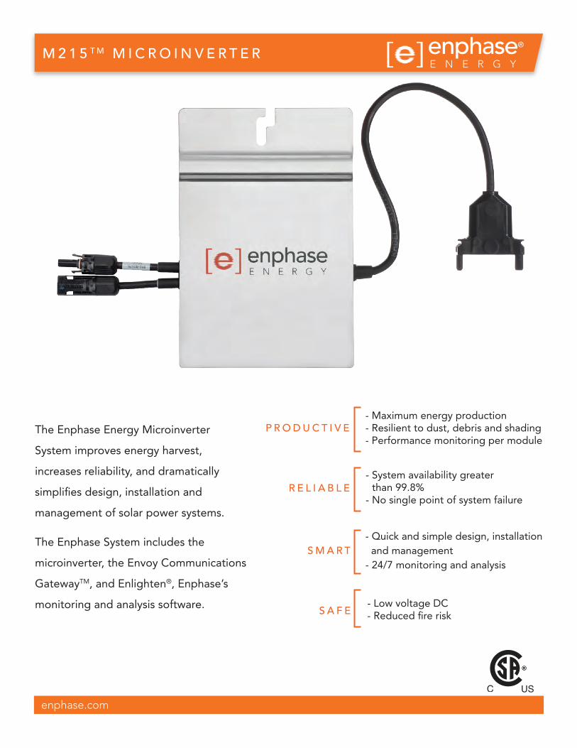
The Enphase Energy Microinverter
System improves energy harvest,
increases reliability, and dramatically
simplifies design, installation and
management of solar power systems.
The Enphase System includes the
microinverter, the Envoy Communications
GatewayTM, and Enlighten®, Enphase’s
monitoring and analysis software.
M 2 1 5 T M M I C R O I N V E R T E R
enphase.com
P R O D U C T I V E
R E L I A B L E
- Maximum energy production - Resilient to dust, debris and shading- Performance monitoring per module
- System availability greater than 99.8%
- No single point of system failure
S M A R T
S A F E
- Quick and simple design, installation and management- 24/7 monitoring and analysis
- Low voltage DC- Reduced fire risk
®

Pairs with most 60-cell PV modulesPower line25-year limited warrantyFree lifetime monitoring via Enlighten softwareUL1741/IEEE1547, FCC Part 15 Class BCAN/CSA-C22.2 NO. 0-M91, 0.4-04, and 107.1-01
Output Data (AC)Maximum output powerNominal output currentNominal voltage/rangeExtended voltage/rangeNominal frequency/rangeExtended frequency rangePower FactorMaximum units per 20A branch circuitMaximum output fault current
Recommended input power (STC)Maximum input DC voltagePeak power tracking voltageOperating rangeMin./Max. start voltageMax. DC short circuit currentMax. input current
CEC weighted efficiencyPeak inverter efficiencyStatic MPPT efficiency (weighted, reference EN50530)Dynamic MPPT efficiency (fast irradiation changes, reference EN50530)Night time power consumption
Efficiency
M215 — MICROINVERTER TECHNICAL DATAInput Data (DC) M215-60-2LL-S22/S23/S24 and M215-60-2LL-S22-NA/S23-NA (Ontario)
190 - 270W45V22V - 36V16V - 36V22V/45V15A10.5A
215W1.0A (arms at nominal duration)
208V/183-229V208V/179-232V60.0/59.3-60.5 Hz60.0/59.2-60.6 Hz>0.9525 (three phase)1.05 Arms, over 3 cycles; 25.2 Apeak, 1.74ms duration
215W0.9A (arms at nominal duration)
240V/211-264V240V/206-269V60.0/59.3-60.5 Hz60.0/59.2-60.6 Hz>0.9517 (single phase)
96.0%96.3%99.6%99.3%46mW
Mechanical Data
-40ºC to + 65ºC-40ºC to + 85ºC17.3 cm x 16.4 cm x 2.5 cm (6.8” x 6.45” x 1.0”)*1.6 kg (3.5 lbs)Natural convection - No fansOutdoor - NEMA 6
Ambient temperature rangeOperating temperature range (internal)Dimensions (WxHxD)WeightCoolingEnclosure environmental rating
Features
CompatibilityCommunicationWarrantyMonitoringCompliance
@208 Vac @240 Vac
Enphase Energy, Inc.1420 N. McDowell BoulevardPetaluma, CA 94954P: [email protected]://www.enphase.com
* without mounting bracket
142-00010, Rev 04b
© 2012 Enphase Energy. All rights reserved.

Installing the Enphase Line Communications Filter (LCF)LCFs are required at large installations that require more than one Envoy Communications GatewayTM. Each Enphase LCF contains an Envoy and termi-nations for phase conductor lines in and out. By running phase conductors through the LCF, it filters power line communications and eliminates any potential inter-Envoy crosstalk in multi-Envoy instal-lations.
Installation Considerations1. The LCF services a maximum number of En-
phase Microinverters per the following table, at a total continuous current of 100 Amps per phase.
208 VAC three-phase, approx 36 kW AC Microinverters supported
M215-60 166
M190-72 189
M210-84 171
240 VAC single-phase, approx 24 kW AC
M215-60 111
M190-72 126
M210-84 114
2. See the unit rating label for the compatible AC voltage requirements.
3. Use NEMA 4-rated, water-tight cable glands and hubs for all conduit entry. These must not compromise the integrity of the LCF’s NEMA enclosure rating.
4. When determining the installation location for the LCF, account for conduit/cable entry for the bottom or side of the LCF enclosure.
5. Select wire size based on ampacity. At a minimum, you will need:• #2-#2/0 copper wire for L1, L2, L3 and neutrals• #8 AWG minimum for line grounding wire• CAT5E or equivalent for Ethernet
6. The LCF terminal blocks have AC fasteners that require compression to a specific torque value during installation. These terminal blocks connect the circuit conductors from PV load center and the grid load center. The terminal block screws must be set to the recommended torque values as specified by the terminal block manufacturer to securely fasten the conductors. See the following sections for wiring steps and for torque values. Over-torqueing the set screws can compromise the performance of the LCF.
7. If you are using aluminum wire, use the specified procedure to install this wire. Refer to the terminal blocks for compatible gauge and wiring type.
Enphase Energy Customer Support: [email protected]
DANGER: Risk of electrical shock. Adhere to all warnings and notes.
WARNING: Installation of the LCF must be done by a qualified electrician.
WARNING: Make sure that power is turned off from the utility and from the solar array before connecting the LCF.
WARNING: Ensure that all connnections are torqued to values listed on the terminal block.
NOTE: Perform all wiring in accordance with the National Electric Code and ANSI/NFPA 70.
NOTE: Improper installation and/or maintenance of an LCF could result in reduced product reliability and/or damage to the product.
NOTE: The LCF must be installed between the utility-side circuit and the array-side circuit protection.
NOTE: Any changes or modifications to Enphase equipment not expressly approved by Enphase Energy could void the user’s authority to operate this equipment.
L C F - Q U I C K I N S TA L L G U I D E®

Mount the LCF1. Use the mounting holes on the back of the LCF
enclosure for installation.
2. Remove all four hole seals and hang the LCF using 8mm mounting hardware with sealing washers.
Wire the LCF1. De-energize all circuits before wiring the LCF.
2. Use antioxidant joint compound on all field termi-nation connection points.
3. On the utility side, use cable ties to hold L1, L2 and L3 together. Allow offset for cable bending.
4. Remove the ferrite core from the assembly bag and slip it over the utility-side wire bundle.
5. Use a torque wrench and the specified hex bit to make the terminations in steps 6, 7 and 8. Tighten the terminals to the torque values specified on the terminal blocks, according to conductor gauge and material. See table.
6. Terminate the utility-side lines to the terminal block labeled “Utility”.
• For black terminal blocks, use a 3/16 wrench that is at least 1.25 inches long.
• For grey terminal blocks, use both a 5mm wrench (at least 1.5 inches long) and a 6mm wrench (at least 1.25 long).
7. Terminate the neutral lines to the block labeled “Neutral” using an 8mm wrench that is at least 1 and 1/8 inches long.
8. Terminate the array-side lines to the terminal block labeled “Array”.
• For black terminal blocks, use a 3/16 wrench that is at least 1.25 inches long.
• For grey terminal blocks, use both a 5mm wrench (at least 1.5 inches long) and a 6mm wrench (at least 1.25 long).
9. Route the ground wires through the LCF so that they make contact with all hubs and con-nect them to the ground bus using an approved grounding connection method.
Marathon Black (Line)
Marathon Grey (Line)
Ferraz Shawmut (Neutral)
2
1
Conductor gauge
Terminal block type and torque specifications
Marathon Black(Line)
Ferraz Shawmut(Neutral)
Marathon Grey(Line)
#2/0 - #6 120 lbf-in --- ---
#2/0 - #1 --- 100 lbf-in 120 lbf-in
#2 - #6 --- 80 lbf-in 80 lbf-in
#8 40 lbf-in 60 lbf-in 40 lbf-in
10. Use a 1/2 inch knockout set to create a conduit knockout on the left side of the enclosure, and pass the CAT5E through the knockout.
11. If needed, to allow the CAT5E to pass through the strain relief, cut and reterminate the CAT5E.
12. Connect the one end of the CAT5E to the Envoy, and connect the other end to the broadband router.
13. After 30 minutes, retighten all terminations to the appro-priate torque value. Do not over-torque.
Terminal Block Types & Torque Specifications
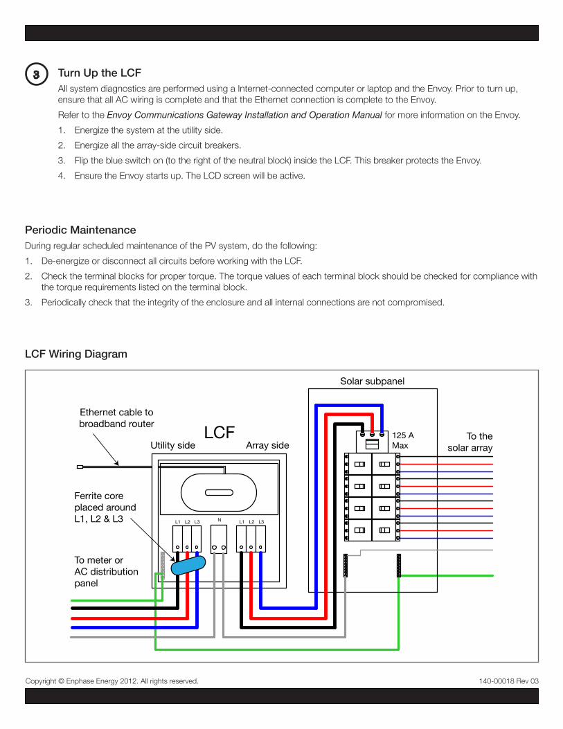
3 Turn Up the LCFAll system diagnostics are performed using a Internet-connected computer or laptop and the Envoy. Prior to turn up, ensure that all AC wiring is complete and that the Ethernet connection is complete to the Envoy.
Refer to the Envoy Communications Gateway Installation and Operation Manual for more information on the Envoy.
1. Energize the system at the utility side.
2. Energize all the array-side circuit breakers.
3. Flip the blue switch on (to the right of the neutral block) inside the LCF. This breaker protects the Envoy.
4. Ensure the Envoy starts up. The LCD screen will be active.
Solar subpanel
Ethernet cable tobroadband router
To meter or AC distribution panel
L1 L3L2 L1 L3L2N
LCF To thesolar array
Ferrite core placed around L1, L2 & L3
Utility side Array side125 A Max
LCF Wiring Diagram
140-00018 Rev 03Copyright © Enphase Energy 2012. All rights reserved.
Periodic MaintenanceDuring regular scheduled maintenance of the PV system, do the following:
1. De-energize or disconnect all circuits before working with the LCF.
2. Check the terminal blocks for proper torque. The torque values of each terminal block should be checked for compliance with the torque requirements listed on the terminal block.
3. Periodically check that the integrity of the enclosure and all internal connections are not compromised.

THE SUN ON YOUR SIDE
Number of Cells: 60 Solar Cell Type: monocrystalline
Power class: 250 Wp
250 / 6 MH PHOTOVOLTAIC MODULE
V With our 30-Year, 80% Power Guarantee, you can be assured top-production for 3 decades
V Industry leading 12 Year, 90% Power Guarantee
V Ideal for all rooftops and ground mount installations
V Easily connected to the grid or used in off-grid scenarios
V Suitable for use on ungrounded PV arrays
V Allows for string size up to 1000 V, which can reduce cost
Three Full Decades of Power - Guaranteed
High Efficiency Modules when Value Matters Most
Quality Tested, Service Assured
Flexible Design
V Only positive tolerances of up to +5 watts ensure maximum power without compromise
V Simple compatibility with any of our inverter partner products to achieve maximum system output
V Certified by the most rigorous US and International standards
V 10-Year Product Warranty
V Built to withstand even the most harsh conditions
1230 10YEARPRODUCTWARRANTY
YEAR 80%POWERGUARANTEE
YEAR 90%POWERGUARANTEE
WATTSPOSITIVETOLERANCES
+5
© M
AGE
SOLA
R PR
OJE
CTS,
INC.
· 1/
2013
· Al
l rig
hts
rese
rved
. Spe
cific
atio
ns in
clud
ed in
this
dat
ashe
et a
re s
ubje
ct to
cha
nge
with
out
notic
e. P
rodu
cts
may
not
be
appl
icab
le fo
r all
area
s. Im
age
may
not
repr
esen
t act
ual m
odul
e.
MAGE SOLAR USA
720 Industrial Boulevard · Dublin, Georgia 31021 USA
Toll-free (877) 311-6243 · Main Office (478) 609-6640 · Fax (478) 275-7685
[email protected] · www.magesolar.com
* STC @ 25° C, 1000 W/m2, AM 1.5
ELECTRICAL CHARACTERISTICS*
Maximum Power Rating Pmp (W) 250
Tolerance of Pmp (W) -0/+5
Maximum Power Voltage of Pmp Vmp (V) 30.40
Maximum Power Current Pmp Imp (A) 8.22
Open Circuit Voltage VOC (V) 37.51
Short Circuit Current ISC (A) 8.88
Maximum System Voltage (V) 1000
Maximum Series Fuse (A) 15
250 / 6 MH PHOTOVOLTAIC MODULE
TECHNICAL FACTS
Number of Cells (Matrix) 60 (6 x 10)
Solar Cell Type monocrystalline
Solar Cell Size (mm) 156 x 156
Solar Cell Size (in) 6 x 6
Dimensions (L x W x H mm) 1636 x 992 x 45
Dimensions (L x W x H in) 64.41 x 39.06 x 1.77
Weight (kg) 19.5
Weight (lbs) 43.0
Module Efficiency (%) 15.4
Connector Type MC4 or equivalent
THERMAL CHARACTERISTICS
NOCT (°C) + 45 ±3
Temperature Coefficient ISC (%/°C) + 0.047
Temperature Coefficient VOC (%/°C) - 0.31
Temperature Coefficient Pmp (%/°C) - 0.41
Unmatched 30–YearPerformanceGuarantee
FSEC CECUL1703
6121561730

Appendix H Electrochromic Glazing Evaluation
for Great Hall

H. Electrochromic Glazing Evaluation for Great Hall The original glazing used in the west curtain wall of Krannert’s Great Hall was made of single pane 1/4 in. clear glass. As part of the photovoltaic study, Hanson was asked to provide energy savings calculations associated with replacing this glass with electrochromic glazing. Hanson used eQuest v3.64 to simulate the existing space generally defined as the Great Hall Foyer with two alternative curtain wall glazing systems. The baseline simulation uses the existing single pane glass. The alternative curtain wall glazing systems modeled were Double Pane Low-E Electrochromic and standard Double Pane Low-E. The standard Double Pane Low-E glass was modeled for the sake of comparison because it was apparent that most of the energy saving resulted from the upgrade to double pane Low-E glass and not from the use of Electrochromic glazing. The UIUC FY2013 variable cost utility rates were used for the analysis as shown in Table H1.1. Table H1.1 Utility Rates: UIUC FY 2013 Variable Rates Utility Rate
Campus Steam $8.29 per klbs Campus Chilled Water $9.89 per Million Btu The results of the simulation are summarized in Table H1.2. Table H1.2 Energy Savings and Cost Results Summary(1)
1. Savings shown are in comparison to 1/4 in. single pane clear glass. 2. These projected savings are derived from a reduction of energy consumption based on building
geometry, construction type, internal loads, assumed use schedules, and average annual weather data. While those results are shown to the nearest $1, they should be considered approximate and for general comparison only.
The results shown in Table H1.2 indicate that the annual energy cost savings associated with replacing the curtain wall with Double Pane Low-E Electrochromic glazing would be $4,196, a substantial portion of which is attributed to the heating savings of upgrading the single pane glass to double pane Low-E glass. The net energy cost savings associated with adding an electrochromic feature to a clear double pane low-E glazing for the great hall foyer at Krannert is therefore estimated to be one thousand three hundred twenty-three dollars ($1,323) [$4,196 - $2,873] per year.
Annual
Heating
Savings
(klb steam)
Annual
Cooling
Savings
(MBtu Chilled
Water)
Annual
Heating
Savings
($) (2)
Annual
Cooling
Savings
($) (2)
Total Annual
Energy Cost
Savings ($) (2)
Double Pane Low-E 344 2 $2,855 $18 $2,873 Double Pane Low-E Electrochromic 322 154 $2,675 $1,521 $4,196
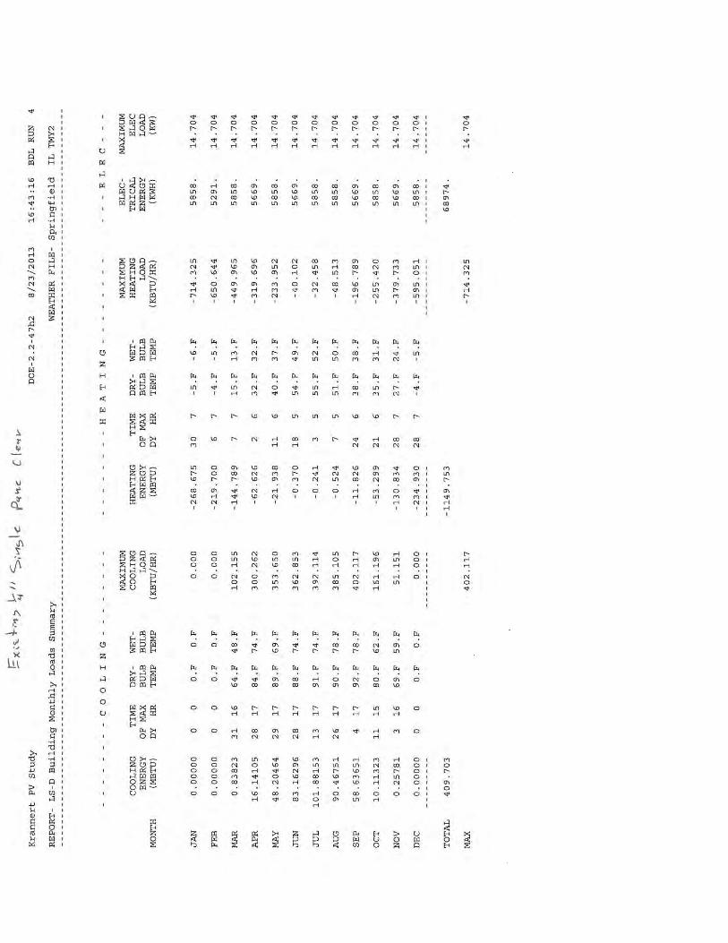


Appendix I UIUC Review Comments

Project Review Krannert Solar Study Architectural Review Comments
Plan Reviewer: McClure
Comment Number
Drawing or Spec
Reference UIUC Facilities & Services Comment AE Response
Drawing Comments
Specification Comments
101 Regarding
access to the roof top for workers
Page 7 mentions a temporary construction stairway on the east side of the building. What is the height from the plaza deck level to the roof top? Would a buck hoist better serve the project? What would that add to the cost?
Building height is 60 ft from the plaza level to the roof at the east end of the building. We looked into a buckhoist and the cost was considered to be prohibitive - around $25,000 for installation, rental and removal.
102 Regarding the Pythagoras Solar Glass
The literature says they have teamed up with "a number of leading glass manufacturers". Which ones?
We can evaluate this further in Phase 2 if the study is so-directed. Other reviewers have commented that the PVGU should not be included in this study
103 When Heat Mirror came on the market it sounded like a great idea. UI experience with it at ACES Library was that in less than 8 years, every piece of the glass had a failed seal in the air space. Some pieces failed within the first year. What assurances are there that this will not happen with the PV's in the middle? How are they inserted and held in the air space? Will they have a potentially adverse impact on the seal?
ditto
104 What does the product cost? Replacement cost for damaged pieces of glass is always a concern for us.
ditto
105 So the Student Sustainability Committee may pay for the installation. What if the product fails? Who will pay to remove the PV glass and re-install regular glass?
UIUC would need to assess how such costs would be borne if outside the manufacturer's warranty period

Plan Reviewer: John Prince
Comment Number
Drawing or Spec
Reference
UIUC Facilities & Services Comment AE Response
Drawing Comments
Specification Comments
Page 3-4 The Executive Summary is in conflict with the project
description. The description called for a study on the use of electro-chromatic glazing on the west wall and its effect on the thermal loading and energy consumption in the Great Hall area. The study only made passing references to photovoltaic glass units and included no analysis. An acceptable submittal must include this requested analysis which was not included in this report. Payback analysis should be both for the replacement and the increased cost of the electro-chromatic system over standard insulated glass units.
Hanson understood the study's focus to be directed to evaluation of capturing of solar energy. The Project's Executive Summary included in the Scope Statement references electro chromic or thin film solar on the west wall of the Great Hall as part of the overall solar energy project. In accordance with discussions at the kick-off meeting, our evaluation was limited to consideration of photovoltaics (thin film solar), and assessment of potentially offsetting HVAC demands through tinting of the glazing on the west curtain wall was not understood to be within the scope of the study.
Page 9 The Photovoltaic Glass evaluation was NOT part of the requested study and should be deleted from this report.
All reference to the PV glazing units can be removed in their entirety if the AE is so directed by UIUC
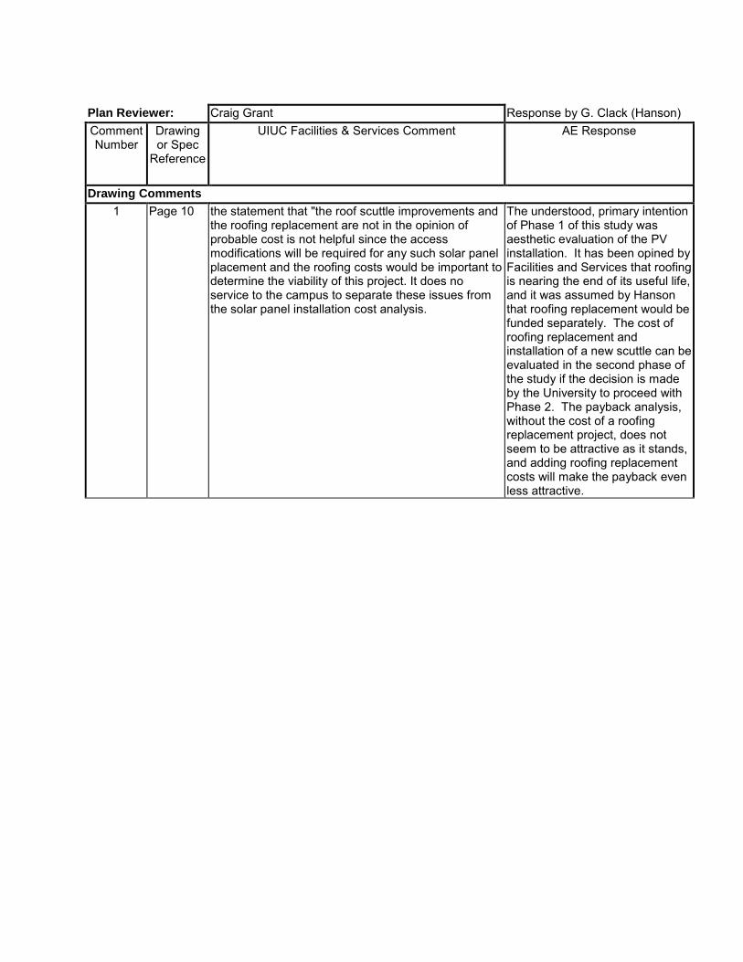
Plan Reviewer: Craig Grant Response by G. Clack (Hanson) Comment Number
Drawing or Spec
Reference
UIUC Facilities & Services Comment AE Response
Drawing Comments
1 Page 10 the statement that "the roof scuttle improvements and the roofing replacement are not in the opinion of probable cost is not helpful since the access modifications will be required for any such solar panel placement and the roofing costs would be important to determine the viability of this project. It does no service to the campus to separate these issues from the solar panel installation cost analysis.
The understood, primary intention of Phase 1 of this study was aesthetic evaluation of the PV installation. It has been opined by Facilities and Services that roofing is nearing the end of its useful life, and it was assumed by Hanson that roofing replacement would be funded separately. The cost of roofing replacement and installation of a new scuttle can be evaluated in the second phase of the study if the decision is made by the University to proceed with Phase 2. The payback analysis, without the cost of a roofing replacement project, does not seem to be attractive as it stands, and adding roofing replacement costs will make the payback even less attractive.

Engineering | Planning | Allied Services
Krannert Center for the Performing Arts Solar Project Feasibility Study University of Illinois at Urbana-Champaign Project Number: U12239 Phase 2 95% Submittal March 25, 2014
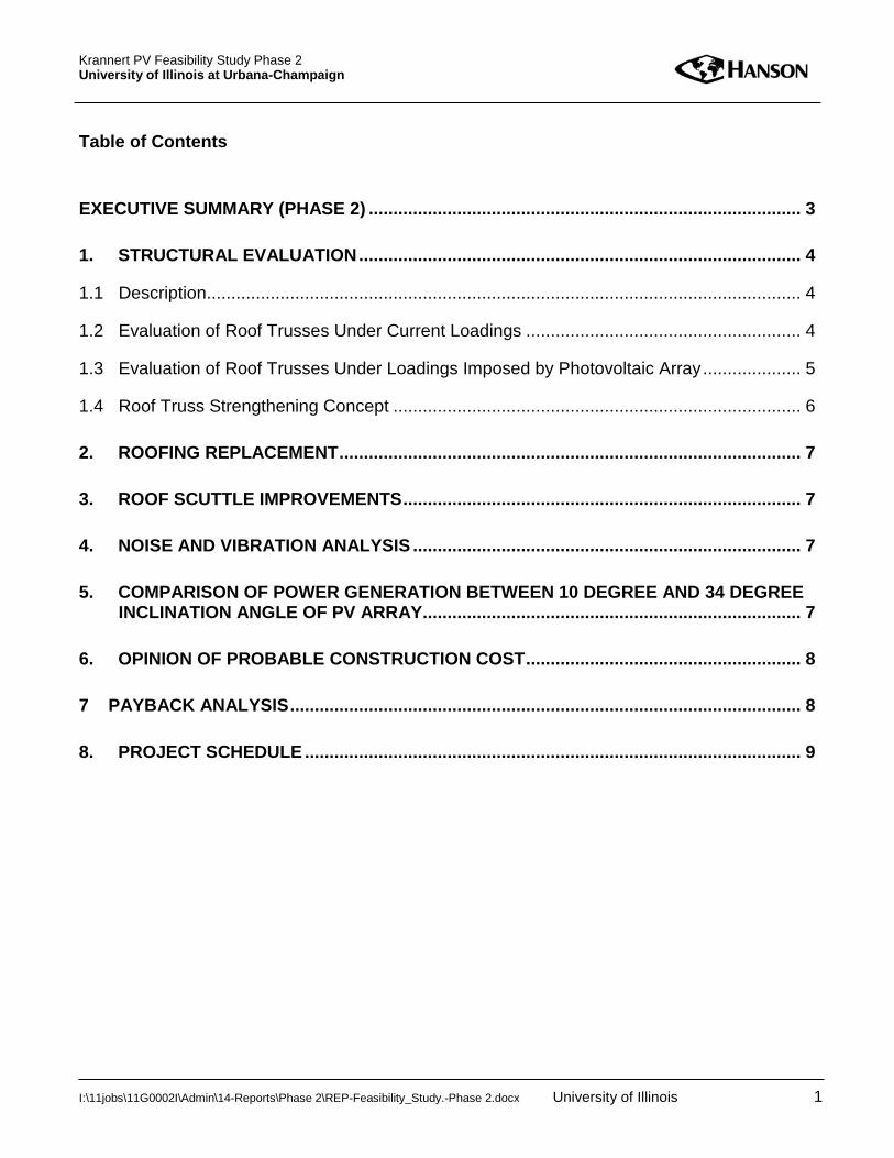
Krannert PV Feasibility Study Phase 2 University of Illinois at Urbana-Champaign
Table of Contents
EXECUTIVE SUMMARY (PHASE 2) ........................................................................................ 3
1. STRUCTURAL EVALUATION .......................................................................................... 4
1.1 Description ......................................................................................................................... 4
1.2 Evaluation of Roof Trusses Under Current Loadings ........................................................ 4
1.3 Evaluation of Roof Trusses Under Loadings Imposed by Photovoltaic Array .................... 5
1.4 Roof Truss Strengthening Concept ................................................................................... 6
2. ROOFING REPLACEMENT .............................................................................................. 7
3. ROOF SCUTTLE IMPROVEMENTS ................................................................................. 7
4. NOISE AND VIBRATION ANALYSIS ............................................................................... 7
5. COMPARISON OF POWER GENERATION BETWEEN 10 DEGREE AND 34 DEGREE INCLINATION ANGLE OF PV ARRAY............................................................................. 7
6. OPINION OF PROBABLE CONSTRUCTION COST ........................................................ 8
7 PAYBACK ANALYSIS ........................................................................................................ 8
8. PROJECT SCHEDULE ..................................................................................................... 9
I:\11jobs\11G0002I\Admin\14-Reports\Phase 2\REP-Feasibility_Study.-Phase 2.docx University of Illinois 1

Krannert PV Feasibility Study Phase 2 University of Illinois at Urbana-Champaign
Appendices Appendix A – Selected Structural Drawings from 1966 Plans by Lev Zetlin Appendix B – Kirkegaard Report – Noise and Vibration Analysis Appendix C – Opinion of Probable Construction Cost – General Work Copyright 2012 by Hanson Professional Services Inc. All rights reserved. This document is intended solely for the individual or the entity to which it is addressed. The information contained in this document shall not be duplicated, stored electronically, or distributed, in whole or in part, by anyone other than the recipient without the express written permission of Hanson Professional Services Inc., 1525 S. Sixth St., Springfield, IL 62703, (217) 788-2450, www.hanson-inc.com. Unauthorized reproduction or transmission of any part of this document is a violation of federal law. Any concepts, designs and project approaches contained herein are considered proprietary. Any use of these concepts and approaches by others is considered a violation of copyright law.
I:\11jobs\11G0002I\Admin\14-Reports\Phase 2\REP-Feasibility_Study.-Phase 2.docx University of Illinois 2

Krannert PV Feasibility Study Phase 2 University of Illinois at Urbana-Champaign
Executive Summary (Phase 2) The purpose of the study is to examine the feasibility of installing a solar photovoltaic (PV) system on one or more of the roofs at Krannert Center for the Performing Arts (KCPA). The study was divided into two phases. Phase 1 of the study presented an assessment of the visual impact on the facility, an opinion of probable construction cost (OPCC), general considerations of construction phasing and associated general construction, and a simple payback analysis for the PV array. Phase 2 of the study, presented herein, further examines:
• the capacity of the existing roof structure, and presents a conceptual level opinion of construction cost for roof strengthening;
• cost of roofing replacement; • concept and opinion of cost for improving maintenance access to the roof; • noise and vibration analysis associated with mounting a photovoltaic array on the roof of the
Great Hall; • general comparison of power generation efficiency between a 10 degree and 34 degree angle
of inclination; and • an updated OPCC.
The Phase 2 assessment has identified deficiencies in the existing roof structure that will need to be addressed prior to the addition of any new loads. General strengthening concepts are described in this report, and a high level OPCC for this roof strengthening is presented. Kirkegaard Associates prepared a general assessment of noise and vibration considerations that should be addressed in the design, and their report is included in Appendix B. The OPCC presented in this Phase 2 of the report includes only the items described above. A recapitulation of costs identified during Phase 1 and Phase 2 are presented in the Summary Report.
I:\11jobs\11G0002I\Admin\14-Reports\Phase 2\REP-Feasibility_Study.-Phase 2.docx University of Illinois 3

Krannert PV Feasibility Study Phase 2 University of Illinois at Urbana-Champaign
1. Structural Evaluation 1.1 Description Phase 2 of the feasibility study included a structural analysis of the existing roof trusses and slabs and the impact of placing photovoltaic cells on the roof structure. Two options for supporting the PV cells were considered. The first was a steel support system. Vertical steel posts would be secured to the existing structure and would support the framing that holds the PV cells. The second option considered vertical concrete knee walls aligned with the trusses that would support the PV cell frames. An acoustical assessment determined that steel supports may more directly transfer wind and other environmental loads to the roof steel. This could potentially exacerbate vibration and noise transmission through the building’s interior. For this reason, the loading of the heavier concrete walls was considered for structural analysis purposes. 1.2 Evaluation of Roof Trusses Under Current Loadings The existing structure was assessed based on the original 1966 drawings prepared by Lev Zetlin and Associates (see Appendix A). The current roof structure consists of a 6 in. reinforced concrete slab supported by steel trusses that span 84 ft across the Great Hall. The trusses are made up of tee-shaped chord members and double-angle web members. Secondary wide flange beams spaced at approximately 21 ft span between the trusses and create two-way action in the slab. Analyses conducted during Phase 1 of this Feasibility Study showed that the secondary components (roof slab and beams) do not have sufficient capacity to support the added load of the photovoltaic array. Consequently, support systems were conceptualized that would deliver the new loads directly to the trusses. Analyses conducted during Phase 2 therefore focused on the roof trusses. Loads and stresses on the trusses were determined using the American Society of Civil Engineers (ASCE) 7-10 design loads and typical material weights. Taking into consideration the dead loads (truss members, roofing materials, concrete slab, catwalks, and ceilings) and snow loads, the total load on the roof structure is estimated to be 130 lbs per sq. ft (see table below). With a distance of 21 ft-4 in. between trusses, this equates to approximately 2,800 lbs per lineal foot applied to the truss.
Existing Load Summary Load (lb/ft2) Truss (Self) 10 Slab 75
Catwalks and Ceilings 13 EPDM Roof 5 Insulation 3 Live Loads (Snow) 25 Total 131 lb/ft2
I:\11jobs\11G0002I\Admin\14-Reports\Phase 2\REP-Feasibility_Study.-Phase 2.docx University of Illinois 4
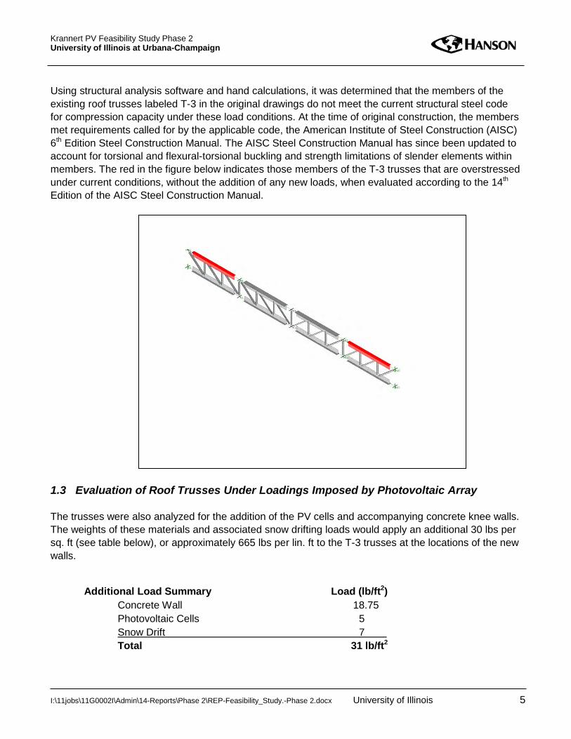
Krannert PV Feasibility Study Phase 2 University of Illinois at Urbana-Champaign
Using structural analysis software and hand calculations, it was determined that the members of the existing roof trusses labeled T-3 in the original drawings do not meet the current structural steel code for compression capacity under these load conditions. At the time of original construction, the members met requirements called for by the applicable code, the American Institute of Steel Construction (AISC) 6th Edition Steel Construction Manual. The AISC Steel Construction Manual has since been updated to account for torsional and flexural-torsional buckling and strength limitations of slender elements within members. The red in the figure below indicates those members of the T-3 trusses that are overstressed under current conditions, without the addition of any new loads, when evaluated according to the 14th Edition of the AISC Steel Construction Manual.
1.3 Evaluation of Roof Trusses Under Loadings Imposed by Photovoltaic Array The trusses were also analyzed for the addition of the PV cells and accompanying concrete knee walls. The weights of these materials and associated snow drifting loads would apply an additional 30 lbs per sq. ft (see table below), or approximately 665 lbs per lin. ft to the T-3 trusses at the locations of the new walls.
Additional Load Summary Load (lb/ft2) Concrete Wall 18.75 Photovoltaic Cells 5
Snow Drift 7 Total 31 lb/ft2
I:\11jobs\11G0002I\Admin\14-Reports\Phase 2\REP-Feasibility_Study.-Phase 2.docx University of Illinois 5

Krannert PV Feasibility Study Phase 2 University of Illinois at Urbana-Champaign
These loads would introduce an additional sixty thousand pounds (approximate) into each of the steel chord members, causing four additional chord members to be stressed beyond code-prescribed limitations, as indicated in blue in the figure below.
1.4 Roof Truss Strengthening Concept Two concepts for strengthening the truss top chord members were considered. Both are anticipated to be complex to execute due to the access constraints. The first concept for strengthening these members involves welding 7/8 in. x 9 in. steel plates to the stems of the tee-shaped chord elements. These plates would increase the compressive strength of the current members such that they would meet the provisions of the current AISC Steel Construction Manual. The second concept for strengthening the trusses would be to post-tension the top and bottom chords of the trusses. Steel cables would run approximately between the 1/4 and 3/4 points of the bottom chord of the truss and then turn and run diagonally towards the top chord bearing points. The cables would be anchored into the top chords and tensioned via a jacking system that would reduce the compression in the top chord and reduce tension in the bottom chord, offsetting the design loads and lowering the stresses experienced by the members to within code-prescribed limitations. This method may reduce the number of points of access required for repair, which may in turn decrease the cost of work as compared to welding plates across the entire chord length.
I:\11jobs\11G0002I\Admin\14-Reports\Phase 2\REP-Feasibility_Study.-Phase 2.docx University of Illinois 6
Krannert PV Feasibility Study Phase 2 University of Illinois at Urbana-Champaign
Because the ceiling of the Great Hall is expected to prevent direct access to the trusses from the Great Hall, any scaffolding built would have to be suspended from the trusses. Given the complex nature of this work, the cost of strengthening the trusses could be in a range between two hundred thousand dollars ($200,000) and three hundred thousand dollars ($300,000). 2. Roofing Replacement During Phase 1 of the study it was identified that the roofing of the Great Hall should be replaced prior to the installation of the photovoltaic array. Drawings detailing the current roof system installed in 1995 were not available for Hanson’s review, and a detailed examination of the roofing will need to be done to determine the extent of replacement needs. For planning purposes, an overall removal and replacement of all flashing, roofing materials, and insulation was considered. An OPCC for this scope of roofing work is approximately twenty dollars ($20) per sq. ft of roof, resulting in an OPCC of three hundred sixty thousand dollars ($360,000) for roofing work at this section of the facility. 3. Roof Scuttle Improvements As identified in Phase 1 of this study, access to the roof is cumbersome and consideration should be given to improving it. It appears that shifting the roof hatch 3 to 4 ft to the south would provide for this direct access. This alternate location is shown on the conceptual roof plan layout of the PV array. Modifications would involve constructing a new opening through the roof structure, in-filling the existing opening, and constructing a new ladder from the Booth Level to the roof in alignment with the new roof hatch. Installation of a safety post that could be extended above the hatch when in use is also recommended. An OPCC for these modifications is fifteen thousand dollars ($15,000). Note that the cost of roof flashing is not considered in this item, as it is accounted for separately under “Roofing Replacement.” 4. Noise and Vibration Analysis Kirkegaard Associates has conducted a general assessment of the potential for noise and vibration disruptions that may result in the Great Hall due to the placement of a roof-mounted photovoltaic array. Kirkegaard’s report is included as Appendix B. General recommendations for decoupling the PV array from the roof structure are presented. The need for additional evaluation is also identified in Kirkegaard’s report. Kirkegaard’s report includes unit costs associated with potential noise and vibration options. Costs for the spring isolator system are compiled in the “General Structural” OPCC. 5. Comparison of Power Generation between 10 degree and 34 degree Inclination
Angle of PV Array The angle of inclination for photovoltaic cells that is recommended for optimizing generation of electricity is based on the location with respect to the earth’s latitude. For this location, the
I:\11jobs\11G0002I\Admin\14-Reports\Phase 2\REP-Feasibility_Study.-Phase 2.docx University of Illinois 7
Krannert PV Feasibility Study Phase 2 University of Illinois at Urbana-Champaign
recommended fixed angle of inclination is approximately 34 degrees. Due to aesthetic objectives to limit the visible projection of the photovoltaic array, it is recommended that the angle of inclination be no more than 10 degrees. The loss of electrical generation efficiency between an angle of inclination of 34 degrees (optimum) and 10 degrees (chosen for aesthetics) is approximately 7 percent. 6. Opinion of Probable Construction Cost An OPCC is included in Phase 1 of the study. However, the OPCC prepared during Phase 1 did not include the cost of truss strengthening, roofing replacement or the cost of modifying the roof access hatch (roof scuttle). The costs presented in the Phase 1 study are included herein for reference. Modifications and additional items are summarized in the Phase 2 column, and those items for which there is no change are carried over as such into the Phase 2 column. These costs are presented below, and a recapitulation of cost is included in the Summary Report. An itemized OPCC for the General Work is included in Appendix C.
ITEM Phase 1 OPCC
Phase 2 OPCC
Roofing Replacement Not included
$360,000
Construction Access and General Construction $128,000 $132,000 Roof Scuttle Improvements Not
included $15,000
Roof Truss Strengthening Not included
$300,000
Noise and Vibration Mitigation Not included
$36,000
Electrical conduit / routing $117,000 $117,000 PV cells and Micro-inverters $326,000 $326,000 Electrical Power Distribution Equipment $10,000 $10,000 Kiosk $4,000 $4000 TOTAL (excluding contingencies) $585,000 $1,300,000
7. Payback Analysis The payback analysis is included in Appendix B of the Phase 1 report. The analysis shows an estimated annual payback (value of generated electricity) of around twelve thousand six hundred dollars ($12,600). The payback period is difficult to assess given the varied nature of collateral work associated with this project. No attempt has been made to assign a dollar value to the benefits of environmental stewardship.
I:\11jobs\11G0002I\Admin\14-Reports\Phase 2\REP-Feasibility_Study.-Phase 2.docx University of Illinois 8
Krannert PV Feasibility Study Phase 2 University of Illinois at Urbana-Champaign
For comparison purposes, a ground-mounted PV array may be expected to have an annual payback of nineteen thousand dollars ($19,000) on the same five hundred eighty-five thousand dollar ($585,000) initial investment. 8. Project Schedule During Phase 1 of the study, it was expressed that on-site construction duration would be no more than eight weeks, assuming a construction schedule that would allow a 40 hour work week, of reasonable blocks of time. Given the additional items of work that were identified during Phase 2, it is recommended that this be increased to no less than 12 weeks.
I:\11jobs\11G0002I\Admin\14-Reports\Phase 2\REP-Feasibility_Study.-Phase 2.docx University of Illinois 9
Appendix A Selected Structural Drawings
from 1966 Plans by Lev Zetlin


Appendix B Kirkegaard Report -
Noise and Vibration Analysis
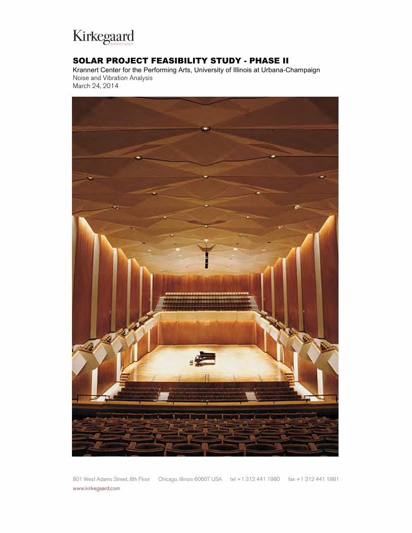
SOLAR PROJECT FEASIBILITY STUDY - PHASE II Krannert Center for the Performing Arts, University of Illinois at Urbana-Champaign Noise and Vibration Analysis March 24, 2014
801 West Adams Street, 8th Floor Chicago, Illinois 60607 USA tel +1 312 441 1980 fax +1 312 441 1981
www.kirkegaard.com
ASSOCIATES
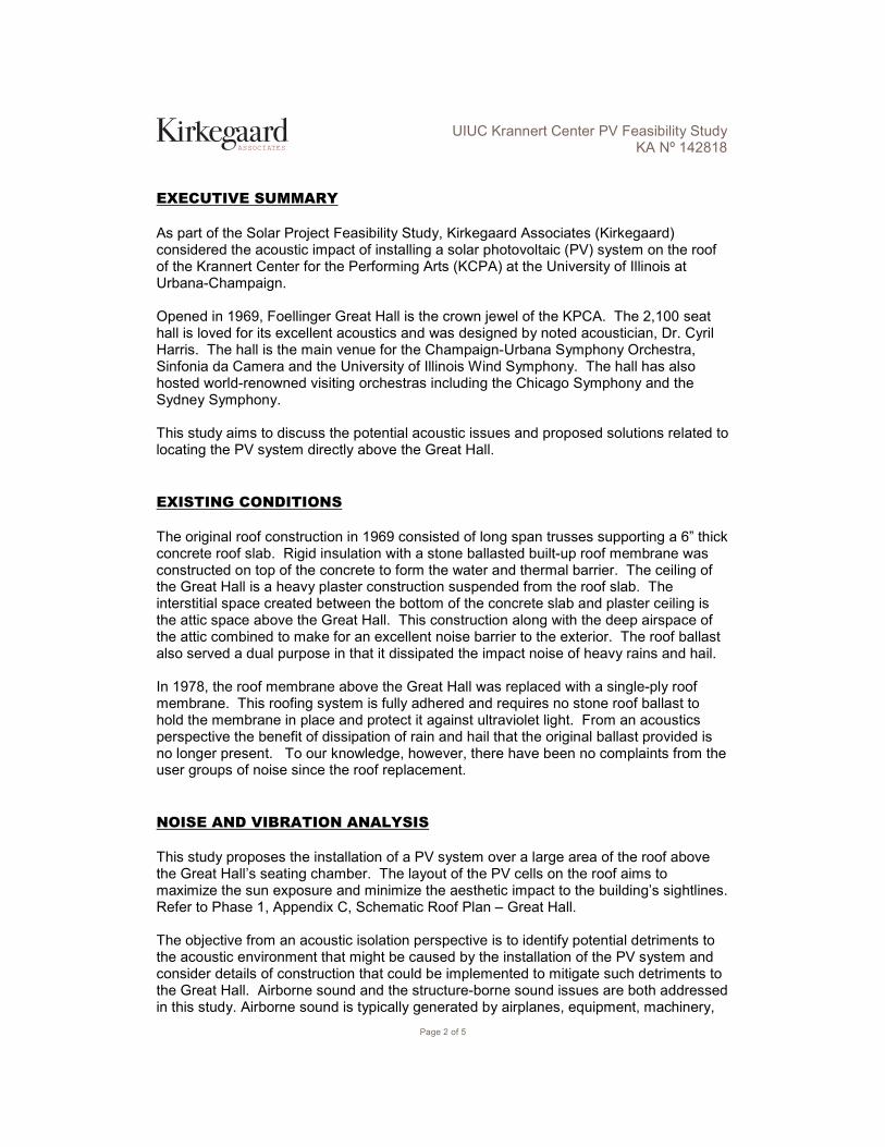
Page 2 of 5
ASSOCIATES
UIUC Krannert Center PV Feasibility Study KA Nº 142818
EXECUTIVE SUMMARY As part of the Solar Project Feasibility Study, Kirkegaard Associates (Kirkegaard) considered the acoustic impact of installing a solar photovoltaic (PV) system on the roof of the Krannert Center for the Performing Arts (KCPA) at the University of Illinois at Urbana-Champaign. Opened in 1969, Foellinger Great Hall is the crown jewel of the KPCA. The 2,100 seat hall is loved for its excellent acoustics and was designed by noted acoustician, Dr. Cyril Harris. The hall is the main venue for the Champaign-Urbana Symphony Orchestra, Sinfonia da Camera and the University of Illinois Wind Symphony. The hall has also hosted world-renowned visiting orchestras including the Chicago Symphony and the Sydney Symphony. This study aims to discuss the potential acoustic issues and proposed solutions related to locating the PV system directly above the Great Hall.
EXISTING CONDITIONS The original roof construction in 1969 consisted of long span trusses supporting a 6” thick concrete roof slab. Rigid insulation with a stone ballasted built-up roof membrane was constructed on top of the concrete to form the water and thermal barrier. The ceiling of the Great Hall is a heavy plaster construction suspended from the roof slab. The interstitial space created between the bottom of the concrete slab and plaster ceiling is the attic space above the Great Hall. This construction along with the deep airspace of the attic combined to make for an excellent noise barrier to the exterior. The roof ballast also served a dual purpose in that it dissipated the impact noise of heavy rains and hail. In 1978, the roof membrane above the Great Hall was replaced with a single-ply roof membrane. This roofing system is fully adhered and requires no stone roof ballast to hold the membrane in place and protect it against ultraviolet light. From an acoustics perspective the benefit of dissipation of rain and hail that the original ballast provided is no longer present. To our knowledge, however, there have been no complaints from the user groups of noise since the roof replacement.
NOISE AND VIBRATION ANALYSIS This study proposes the installation of a PV system over a large area of the roof above the Great Hall’s seating chamber. The layout of the PV cells on the roof aims to maximize the sun exposure and minimize the aesthetic impact to the building’s sightlines. Refer to Phase 1, Appendix C, Schematic Roof Plan – Great Hall. The objective from an acoustic isolation perspective is to identify potential detriments to the acoustic environment that might be caused by the installation of the PV system and consider details of construction that could be implemented to mitigate such detriments to the Great Hall. Airborne sound and the structure-borne sound issues are both addressed in this study. Airborne sound is typically generated by airplanes, equipment, machinery,
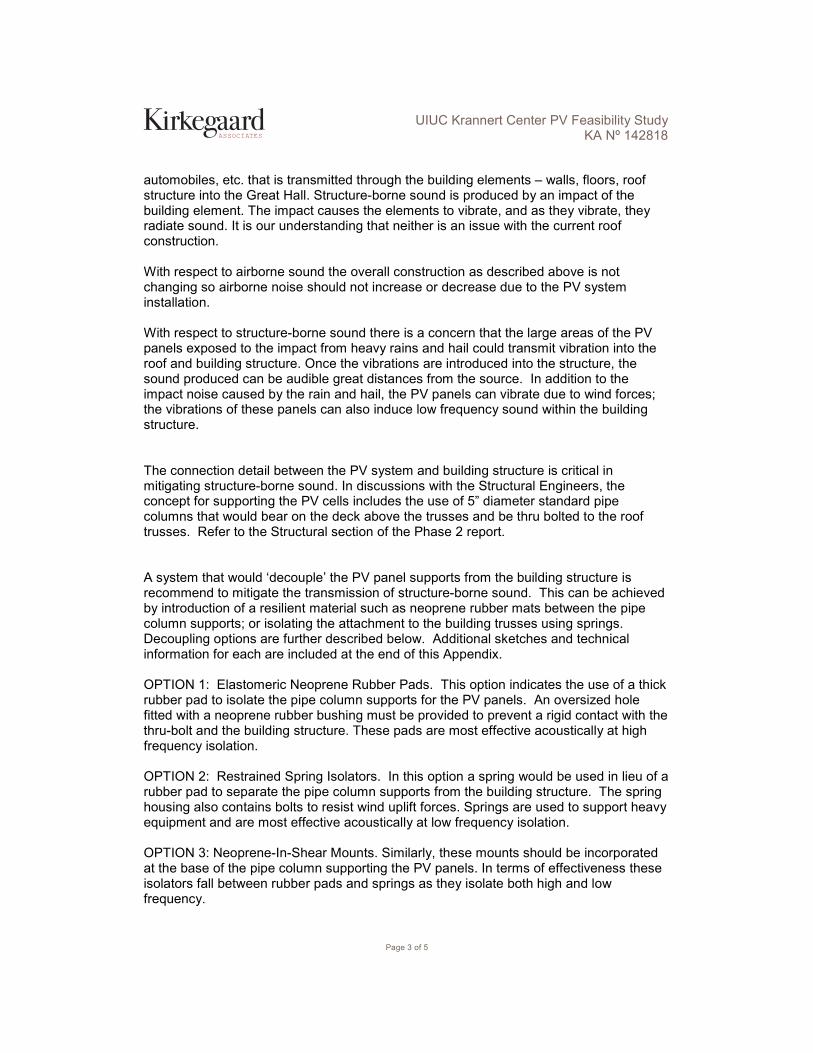
Page 3 of 5
ASSOCIATES
UIUC Krannert Center PV Feasibility Study KA Nº 142818
automobiles, etc. that is transmitted through the building elements – walls, floors, roof structure into the Great Hall. Structure-borne sound is produced by an impact of the building element. The impact causes the elements to vibrate, and as they vibrate, they radiate sound. It is our understanding that neither is an issue with the current roof construction. With respect to airborne sound the overall construction as described above is not changing so airborne noise should not increase or decrease due to the PV system installation. With respect to structure-borne sound there is a concern that the large areas of the PV panels exposed to the impact from heavy rains and hail could transmit vibration into the roof and building structure. Once the vibrations are introduced into the structure, the sound produced can be audible great distances from the source. In addition to the impact noise caused by the rain and hail, the PV panels can vibrate due to wind forces; the vibrations of these panels can also induce low frequency sound within the building structure. The connection detail between the PV system and building structure is critical in mitigating structure-borne sound. In discussions with the Structural Engineers, the concept for supporting the PV cells includes the use of 5” diameter standard pipe columns that would bear on the deck above the trusses and be thru bolted to the roof trusses. Refer to the Structural section of the Phase 2 report. A system that would ‘decouple’ the PV panel supports from the building structure is recommend to mitigate the transmission of structure-borne sound. This can be achieved by introduction of a resilient material such as neoprene rubber mats between the pipe column supports; or isolating the attachment to the building trusses using springs. Decoupling options are further described below. Additional sketches and technical information for each are included at the end of this Appendix. OPTION 1: Elastomeric Neoprene Rubber Pads. This option indicates the use of a thick rubber pad to isolate the pipe column supports for the PV panels. An oversized hole fitted with a neoprene rubber bushing must be provided to prevent a rigid contact with the thru-bolt and the building structure. These pads are most effective acoustically at high frequency isolation. OPTION 2: Restrained Spring Isolators. In this option a spring would be used in lieu of a rubber pad to separate the pipe column supports from the building structure. The spring housing also contains bolts to resist wind uplift forces. Springs are used to support heavy equipment and are most effective acoustically at low frequency isolation. OPTION 3: Neoprene-In-Shear Mounts. Similarly, these mounts should be incorporated at the base of the pipe column supporting the PV panels. In terms of effectiveness these isolators fall between rubber pads and springs as they isolate both high and low frequency.

Page 4 of 5
ASSOCIATES
UIUC Krannert Center PV Feasibility Study KA Nº 142818
The above three options are thought to be capable of providing the resiliency needed to decouple the PV panels from the building structure. In order for the selected option to perform effectively, it must be appropriately sized to avoid overloading the isolators. In the case of the springs, the springs must be compressed to achieve the ideal isolation performance. The PV panels may be too light and additional weight may be needed in order to properly deflect the springs. The costs for these “decoupling” connections can range as follows:
o Option 1: Kinetics Elastomeric Isolator Model RSP are approximately $3 per 2”x2” pads.
o Option 2: Kinetics Restrained Spring Isolator Model FLSS 4 are approximately $500 per isolator.
o Option 3: Kinetics Elastomeric Isolators Model RD are approximately $13 per isolator.
NEXT STEPS
Kirkegaard has identified three options to isolate the PV panels from the building structure. Within the scope of this Feasibility Study, however, it cannot be determined which option is most appropriate for the project. If the project is advanced to the design phase, additional analyses of the existing conditions and a mock-up are recommended as follows:
1. In-situ Isolation Testing – conduct impact isolation testing to measure the performance of the existing roof structure. This testing involves the use of a specialized tapping machine to meet current ASTM standards.
2. Further assess the structure for potential flanking paths for noise and vibration to gain a better understanding of the existing conditions and aid in the selection of an isolation approach.
3. Construct a full size mock-up or prototype installation of one of the PV panels on top of the roof. This is intended to simulate some of the conditions that the PV panels will encounter and provide the designers with better feedback than any computer model can predict. The mock-up would also be useful in confirming (or disproving) the assessment of the aesthetic impact of the installation of the PV array and could also aid in evaluating the effects of wind on the panels.
CONCLUSION
This Feasibility Study presents general considerations and possible options for noise and vibration mitigation that would be a necessary component of the installation of a photovoltaic array on the roof over the Great Hall. Recognizing that effective isolation of noise and vibration is critical to the function of this space, it is strongly encouraged that final selection of a vibration isolation system be guided by additional site assessments, including full scale mock-up testing.

Page 5 of 5
ASSOCIATES
UIUC Krannert Center PV Feasibility Study KA Nº 142818
Attachments Roof / Ceiling Isolation Conceptual Panel Support System Panel Frame Decoupling– Option 1: Rubber Pads Panel Frame Decoupling– Option 2: Spring Isolators Panel Frame Decoupling– Option 3: Neoprene-In-Shear Mounts


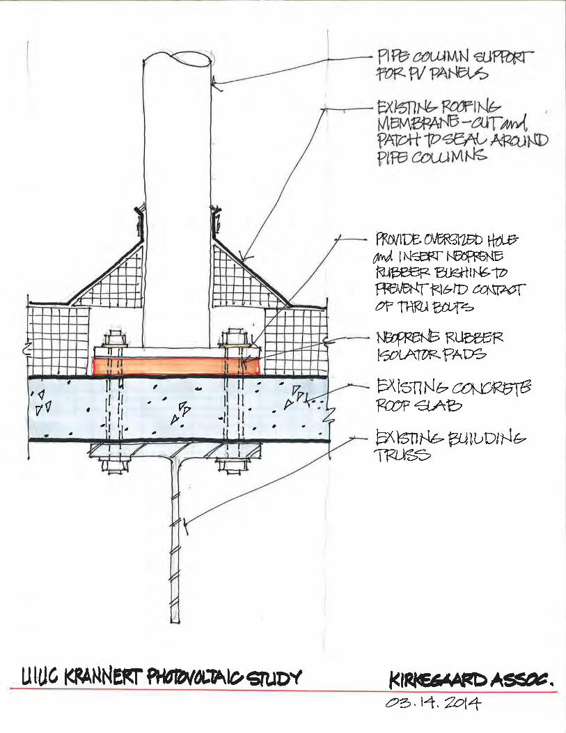

KINETICSTM
ElastomericIsolators
Model RSP
Application and DescriptionKinetics RSP neoprene pads are produced from a high quality neoprene elastomer. Pads are 50 durometer and are designed for a maximum of 60 psi (4.2 kg. / sq. cm) loading. Pads are designed for a maximum deflection of approximately 20% of its unloaded thickness, 0.15'' (0.38 cm). Several layers of RSP pads can be stacked for additional deflection when steel separation shim stock is used. The elastomer is oil and water resistant, offers a long life expectancy consistent with neoprene compounds, and has been designed to operate within the safe stress limits of the material. RSP pads are available in 18'' x 18'' x 3/4'' (457 mm x 457 mm x 19 mm) thick sheets and are pre-scored into 2'' x 2'' (51 mm x 51 mm) squares.
Kinetics Model RSP elastomer in-shear isolation pads are suitable for the isolation of noise, shock, and high frequency vibration produced by mechanical, industrial, or process equipment located on grade, structural slab, or in other non-critical areas.
Applications for Model RSP pads should be limited to pad loadings not to exceed 60 lb. / sq. inch (4.2 kg. / sq. cm.) and are typically used with equipment or machinery having lowest operating speeds of 3600 rpm. Under shock or impact loading, the load capacity of the pads should be reduced by 50%.
Features• Elastomer in-shear neoprene pads• Oil, Water, and Corrosion resistant• Available in 18'' x 18'' x 3/4''
(457 mm x 457 mm x 19 mm) sheets, scored into 2'' x 2'' (51 mm x 51 mm) squares
• Load Capacities from 10 (0.7 kg. / sq. cm.) to 60 (4.2 kg. / sq. cm.) psi
• Static Deflections up to 0.15'' (4 mm)

RSP 8/09
United States6300 Irelan Place P.O. Box 655Dublin, Ohio 43017Phone: 614-889-0480Fax: 614-889-0540
Canada3570 Nashua Drive
Mississauga, OntarioL4V 1L2
Phone: 905-670-4922Fax: 905-670-1698
Kinetics Noise Control, Inc. is continually upgrading the quality of our products. We reserve the right to make changes to this and all products without notice.
SpecificationsIsolation pads shall be neoprene elastomer in-shear pads, used in conjunction with steel shims where required, having static deflections as tabulated.
All pads shall be elastomer in-shear and shall be molded using 2500 psi minimum tensile strength, oil resistant neoprene compounds with no color additives.
Pads shall be 50 durometer and designed to permit 60 psi (4.2 kg. / sq. cm.) loading at a maximum rated deflection of 0.15'' (4 mm). Pads shall be available in 18'' x 18'' x 3/4'' (457 mm x 457 mm x 19 mm) thick sheets, scored into 2'' x 2'' x 3/4'' (51 mm x 51 mm x 19 mm) thick pads. When two isolation pads are laminated, they shall be separated by, and bonded to, a galvanized steel shim plate.
Neoprene vibration isolators shall have minimum operating static deflections as shown on the Vibration Isolation Schedule, or as indicated on the project documents, but not exceeding published load capabilities.
Neoprene vibration isolators shall be model RSP as manufactured by Kinetics Noise Control, Inc.
18''(45.7 cm)
18''(45.7 cm)
Full Sheet is 18'' x 18'' x 3/4''Contains 81 - 2'' x 2'' PadsMax. Load Rating for each 2'' x 2''Pad is 240 lbs. (109 Kg)


KINETICSTM
Restrained Spring IsolatorsModel FLSS 4
DescriptionKinetics Model FLSS Seismic Control Restrained Spring Vibration Isolators consist of free-standing, large diameter, laterally stable steel springs assembled into welded steel housing assemblies. The housings are fabricated to limit vertical movement of the isolated equipment if equipment loads are reduced or if the equipment is subjected to large external forces such as high winds or seismic events. The housings also provide a constant free and operating height to facilitate installation.
Spring elements are complete with internal noise isolation pads and leveling bolts as a part of the top load plate assembly. Holes are provided in all isolators for bolting to the structure and the supported equipment. To assure stability, the springs have a lateral spring stiffness greater than 1.2 times the rated vertical stiffness and are designed to provide a minimum overload capacity of 50%.
FLSS isolators are available with deflections to 4 in. (100 mm) and with load capacities to 23,200 lbs. (10523 kg) as standard products. Custom isolators with higher deflection and greater load capabilities are also available. Kinetics Model FLSS Spring Isolators are recommended for the isolation of vibration produced by equipment carrying a large fluid load which may be drained, such as boilers and chillers, and for the isolation of cooling towers, air-cooled condensers, etc., where motion due to wind loads must be minimized.
ApplicationKinetics Model FLSS Seismic Control Restraint Spring Isolators are recommended as a noise and vibration isolator for mechanical equipment under the following conditions:
1. When the mechanical equipment is located above or near noise and vibration sensitive areas.
2. When the mechanical equipment is subjected to seismic events, high wind loads or other external forces.
3. When the equipment to be isolated has significant changes of weight due to fluid drainage during maintenance operations such as boilers, chillers and cooling towers.
Operating static deflections are available up to 4 in. (100 mm) to maintain a high degree of noise and vibration control while compensating for long span flexible floor structures.
SpecificationVibration isolators shall be seismically rated, restrained spring isolators for equipment which is subject to load variations and large external forces. Isolators shall consist of large diameter, laterally stable, steel springs assembled into welded steel housing assemblies designed to limit movement of the supported equipment in all directions.
Housing assembly shall be of fabricated steel members and shall consist of a top load plate complete with adjusting and leveling bolts, adjustable vertical restraints, isolation washers, and a bottom plate with internal non-skid noise isolation pads and holes for anchoring of housing to supporting structure. Housing shall be hot-dip galvanized for corrosion resistance. Housing shall be designed to provide a constant free and operating height within 1/8 in. (3 mm).
The isolator housing shall provide seismic and wind restraint required by current building codes.
Spring elements shall be selected to provide static deflec-tions as shown on the vibration isolation schedule or as indicated or required in the project documents. Springs shall be color coded or otherwise identified.
Spring elements shall have a lateral stiffness greater than 1.2 times the rated vertical stiffness and shall be de-signed to provide a minimum of 50% overload capacity. Non-welded spring elements shall be polyester powder coated, and shall have a 1000 hr rating when tested in accordance with ASTM B-117.
Vibration isolators shall be Model FLSS as manufacturedby Kinetics Noise Control, Inc.

FLSS-4 6/12
United States6300 Irelan Place P.O. Box 655Dublin, Ohio 43017Phone: 614-889-0480Fax: 614-889-0540
Canada3570 Nashua Drive
Mississauga, OntarioL4V 1L2
Phone: 905-670-4922Fax: 905-670-1698
Kinetics Noise Control, Inc. is continually upgrading the quality of our products. We reserve the right to make changes to this and all products without notice.
IsolatorTypeFLSS-4-100FLSS-4-250FLSS-4-500FLSS-4-750FLSS-4-1000FLSS-4-1250FLSS-4-1600
FLSS-4-2250FLSS-4-2500FLSS-4-2750FLSS-4-3000FLSS-4-3250FLSS-4-3500FLSS-4-3850FLSS-4-4200FLSS-4-4450FLSS-4-4700FLSS-4-4950FLSS-4-5200FLSS-4-5450FLSS-4-5800
FLSS-4-5500FLSS-4-6000FLSS-4-6500FLSS-4-7000FLSS-4-7700FLSS-4-8400FLSS-4-8900FLSS-4-9400FLSS-4-9900FLSS-4-10400FLSS-4-10900FLSS-4-11600
FLSS-4-11000FLSS-4-12000FLSS-4-13000FLSS-4-14000FLSS-4-15400FLSS-4-16800FLSS-4-17800FLSS-4-18800FLSS-4-19800FLSS-4-20800FLSS-4-21800FLSS-4-23200
SpringColorGrayBlueGrnBlackRedBrownOrange
BeigeBge/BluBge/GrnBge/BlkBge/RedBge/BrnBge/OrgChromeChr/BluChr/GrnChr/BlkChr/RedChr/BrnChr/Org
Bge/GrnBge/BlkBge/RedBge/BrnBge/OrgChromeChr/BluChr/GrnChr/BlkChr/RedChr/BrnChr/Org
Bge/GrnBge/BlkBge/RedBge/BrnBge/OrgChromeChr/BluChr/GrnChr/BlkChr/RedChr/BrnChr/Org
lbs.
100250500750
100012501600
22502500275030003250350038504200445047004950520054505800
550060006500700077008400890094009900
104001090011600
110001200013000140001540016800178001880019800208002180023200
kg
45113227340454567726
10211134124713611474158817461905201821322245235924722631
249527222948317534933810403742644491471749445262
4990544358976350698576208074852889819435988810523
RatedCapacity
in.
4.004.004.004.004.004.004.00
4.004.004.004.004.004.004.004.004.004.004.004.004.004.00
4.004.004.004.004.004.004.004.004.004.004.004.00
4.004.004.004.004.004.004.004.004.004.004.004.00
mm
102102102102102102102
102102102102102102102102102102102102102102
102102102102102102102102102102102102
102102102102102102102102102102102102
RatedDeflection
in.
5.635.635.635.635.635.635.63
8.008.008.008.008.008.008.008.008.008.008.008.008.008.00
8.008.008.008.008.008.008.008.008.008.008.008.00
8.008.008.008.008.008.008.008.008.008.008.008.00
mm
143143143143143143143
203203203203203203203203203203203203203203
203203203203203203203203203203203203
203203203203203203203203203203203203
SpringO.D.
in.
11.0011.0011.0011.0011.0011.0011.00
16.2516.2516.2516.2516.2516.2516.2516.2516.2516.2516.2516.2516.2516.25
26.0026.0026.0026.0026.0026.0026.0026.0026.0026.0026.0026.00
27.0027.0027.0027.0027.0027.0027.0027.0027.0027.0027.0027.00
mm
279279279279279279279
413413413413413413413413413413413413413413
660660660660660660660660660660660660
686686686686686686686686686686686686
Lin.
6.006.006.006.006.006.006.00
8.008.008.008.008.008.008.008.008.008.008.008.008.008.00
8.008.008.008.008.008.008.008.008.008.008.008.00
17.0017.0017.0017.0017.0017.0017.0017.0017.0017.0017.0017.00
mm
152152152152152152152
203203203203203203203203203203203203203203
203203203203203203203203203203203203
432432432432432432432432432432432432
Win.
0.690.690.690.690.690.690.69
0.690.690.690.690.690.690.690.690.690.690.690.690.690.69
0.690.690.690.690.690.690.690.690.690.690.690.69
0.810.810.810.810.810.810.810.810.810.810.810.81
mm
17171717171717
1717171717171717171717171717
171717171717171717171717
212121212121212121212121
Din.
0.560.560.560.560.560.560.56
0.690.690.690.690.690.690.690.690.690.690.690.690.690.69
0.690.690.690.690.690.690.690.690.690.690.690.69
0.690.690.690.690.690.690.690.690.690.690.690.69
mm
14141414141414
1717171717171717171717171717
171717171717171717171717
171717171717171717171717
din.
14.0014.0014.0014.0014.0014.0014.00
17.2517.2517.2517.2517.2517.2517.2517.2517.2517.2517.2517.2517.2517.25
17.2517.2517.2517.2517.2517.2517.2517.2517.2517.2517.2517.25
17.2517.2517.2517.2517.2517.2517.2517.2517.2517.2517.2517.25
mm
330330330330330330330
381381381381381381381381381381381381381381
387387387387387387387387387387387387
387387387387387387387387387387387387
H
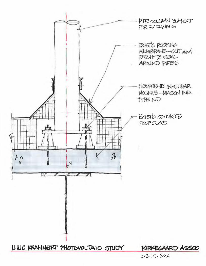
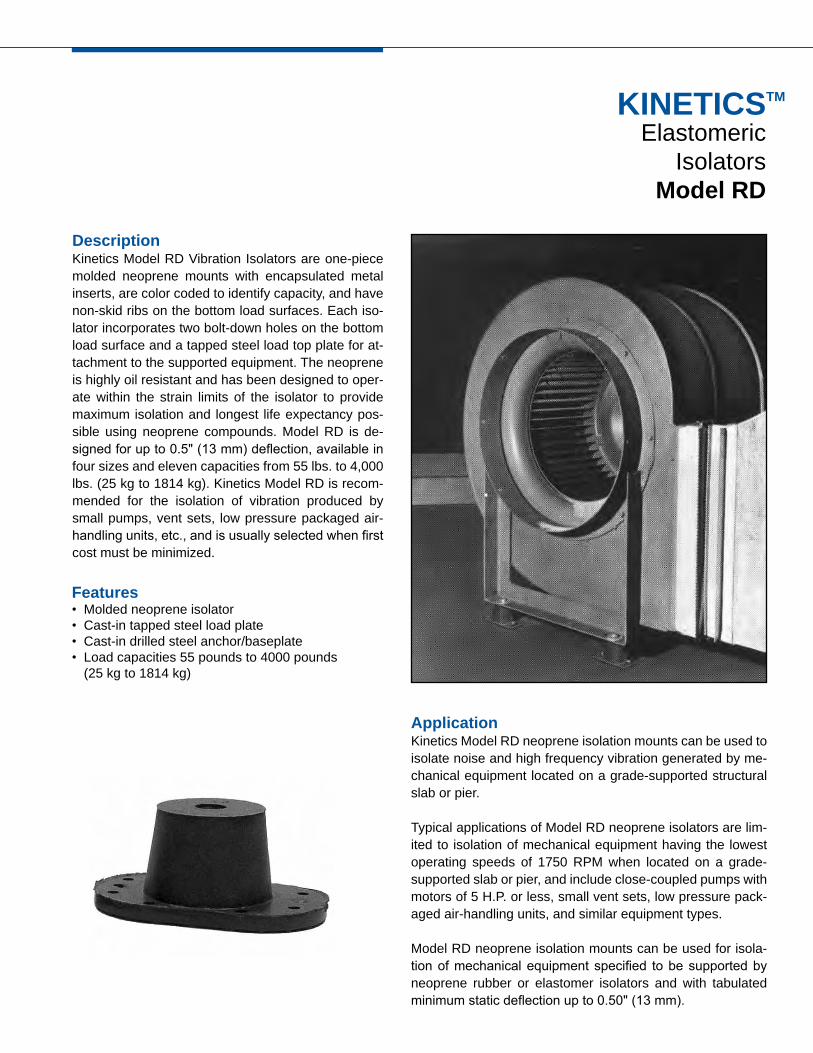
KINETICSTM
ElastomericIsolators
Model RD
DescriptionKinetics Model RD Vibration Isolators are one-piece molded neoprene mounts with encapsulated metal inserts, are color coded to identify capacity, and have non-skid ribs on the bottom load surfaces. Each iso-lator incorporates two bolt-down holes on the bottom load surface and a tapped steel load top plate for at-tachment to the supported equipment. The neoprene is highly oil resistant and has been designed to oper-ate within the strain limits of the isolator to provide maximum isolation and longest life expectancy pos-sible using neoprene compounds. Model RD is de-signed for up to 0.5" (13 mm) deflection, available in four sizes and eleven capacities from 55 lbs. to 4,000 lbs. (25 kg to 1814 kg). Kinetics Model RD is recom-mended for the isolation of vibration produced by small pumps, vent sets, low pressure packaged air-handling units, etc., and is usually selected when first cost must be minimized.
ApplicationKinetics Model RD neoprene isolation mounts can be used to isolate noise and high frequency vibration generated by me-chanical equipment located on a grade-supported structural slab or pier.
Typical applications of Model RD neoprene isolators are lim-ited to isolation of mechanical equipment having the lowest operating speeds of 1750 RPM when located on a grade-supported slab or pier, and include close-coupled pumps with motors of 5 H.P. or less, small vent sets, low pressure pack-aged air-handling units, and similar equipment types.
Model RD neoprene isolation mounts can be used for isola-tion of mechanical equipment specified to be supported by neoprene rubber or elastomer isolators and with tabulated minimum static deflection up to 0.50" (13 mm).
Features• Molded neoprene isolator• Cast-in tapped steel load plate• Cast-in drilled steel anchor/baseplate• Load capacities 55 pounds to 4000 pounds
(25 kg to 1814 kg)

RD 7/12Kinetics Noise Control, Inc. is continually upgrading the quality of our products. We reserve the right to make changes to this and all products without notice.
kineticsnoise.com/hvac/[email protected]
Dublin, Ohio, USA Las Vegas, Nevada, USA Toronto, Ontario, Canada Hong Kong, China
A
EH
C
L
(2 PLACES)D DIA
W
(TAPPED HOLE)B DIA
SpecificationsVibration isolators shall be neoprene, molded from oil-resistant compounds, with cast-in-top steel load transfer plate for bolting to supported equipment, and a bolt-down plate with holes provided for anchoring to supporting structure. Bottom surfaces shall have non-skid ribs.
Neoprene vibration isolators shall have minimum operating static deflections as shown on the Vibration Isolation Schedule or as indicated on the project documents but not exceeding published load capabilities.
Neoprene vibration isolators shall be Model RD, as manufactured by Kinetics Noise Control, Inc.
IsolatorType
RDA-55RDA-125
RDB-120RDB-220RDB-375
RDC-250RDC-600RDC-1100
RDD-2250RDD-3000RDD-4000
lbs
55125
120220375
2506001100
225030004000
Duro
5070
455565
556070
506070
Color
YellowBlue
OrangeGreenBlue
YellowBlueWhite
RedGreenGray
kg
2557
54100170
113272499
102113611814
in
0.400.40
0.500.500.50
0.500.500.50
0.500.500.50
mm
1010
131313
131313
131313
in
3.193.19
3.883.883.88
5.505.505.50
6.256.256.25
mm
8181
989898
140140140
159159159
in
1.811.81
2.382.382.38
3.253.253.25
4.634.634.63
mm
4646
606060
838383
118118118
in
1.251.25
1.751.751.75
2.502.502.50
3.753.753.75
mm
3232
444444
646464
959595
in
0.310.31
0.380.380.38
0.500.500.50
0.500.500.50
mm
88
101010
131313
131313
in
2.382.38
3.003.003.00
4.134.134.13
5.005.005.00
mm
6060
767676
105105105
127127127
in
0.340.34
0.340.340.34
0.560.560.56
0.560.560.56
mm
99
999
141414
141414
in
0.190.19
0.250.250.25
0.250.250.25
0.380.380.38
mm
55
666
666
101010
in
1.501.50
1.751.751.75
2.502.502.50
2.752.752.75
mm
3838
444444
646464
707070
RatedLoad
RatedDeflection L W A B C D E H

Appendix C Opinion of Probable
Construction Cost - General Work
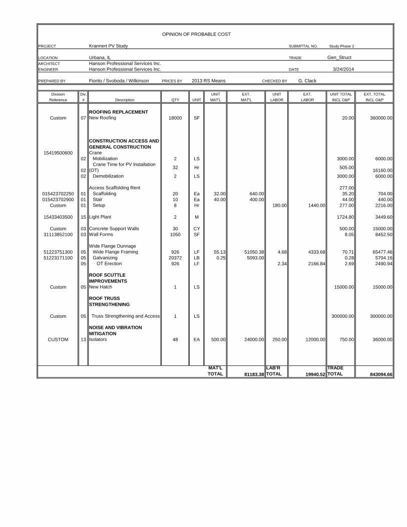
OPINION OF PROBABLE COST
PROJECT Krannert PV Study SUBMITTAL NO. Study Phase 2
LOCATION Urbana, IL TRADE Gen_Struct
ARCHITECT Hanson Professional Services Inc.
ENGINEER Hanson Professional Services Inc. DATE 3/24/2014
PREPARED BY Fiorito / Svoboda / Wilkinson PRICES BY 2013 RS Means CHECKED BY G. Clack
Division Div. UNIT EXT. UNIT EXT. UNIT TOTAL EXT. TOTAL
Reference # Description QTY UNIT MAT'L MAT'L LABOR LABOR INCL O&P INCL O&P
ROOFING REPLACEMENT
Custom 07 New Roofing 18000 SF 20.00 360000.00
CONSTRUCTION ACCESS AND
GENERAL CONSTRUCTION
15419500600 Crane
02 Mobilization 2 LS 3000.00 6000.00
02
Crane Time for PV Installation
(OT)32 Hr 505.00
16160.00
02 Demobilization 2 LS 3000.00 6000.00
Access Scaffolding Rent 277.00
015423702250 01 Scaffolding 20 Ea 32.00 640.00 35.20 704.00
015423702900 01 Stair 10 Ea 40.00 400.00 44.00 440.00
Custom 01 Setup 8 Hr 180.00 1440.00 277.00 2216.00
15433403500 15 Light Plant 2 M 1724.80 3449.60
Custom 03 Concrete Support Walls 30 CY 500.00 15000.00
31113852100 03 Wall Forms 1050 SF 8.05 8452.50
Wide Flange Dunnage
51223751300 05 Wide Flange Framing 926 LF 55.13 51050.38 4.68 4333.68 70.71 65477.46
51223171100 05 Galvanizing 20372 LB 0.25 5093.00 0.28 5704.16
05 OT Erection 926 LF 2.34 2166.84 2.69 2490.94
ROOF SCUTTLE
IMPROVEMENTS
Custom 05 New Hatch 1 LS 15000.00 15000.00
ROOF TRUSS
STRENGTHENING
Custom 05 Truss Strengthening and Access 1 LS 300000.00 300000.00
NOISE AND VIBRATION
MITIGATION
CUSTOM 13 Isolators 48 EA 500.00 24000.00 250.00 12000.00 750.00 36000.00
MAT'L
TOTAL 81183.38
LAB'R
TOTAL 19940.52
TRADE
TOTAL 843094.66