feasibility study on improving of 5-seater...
TRANSCRIPT

FEASIBILITY STUDY ON IMPROVING OF 5-SEATER HELICOPTER
FORWARD FLIGHT SPEED
NIK AHMAD RIDHWAN B. NIK MOHD
A thesis submitted in fulfilment of the
requirements for the award of the degree of
Master of Engineering (Mechanical)
Faculty of Mechanical Engineering
Universiti Teknologi Malaysia
JULY 2006

Dedicated to my beloved parents and family, and to my wife…
Thank you for the endless support and encouragement. You all always have a special place in my heart.

vii
ACKNOWLEDGEMENT
I would like to give my deepest gratitude to my academic and thesis advisor,
Prof. Dr. Ir. Hj. Abas b. Ab. Wahab for his support, guidance, insight, and vision of
this project. His understanding, patience, and unbelievable kindness became a source
of encouragement and strength to me to complete this research. I am very honored
and grateful to have had such a unique opportunity to work under his instruction on a
very exciting and challenging research topic at UTM.
I would like to thank the Malaysia Ministry of Science, Technology and
Innovation (MOSTI) for providing me support and funding for one and half years
through National Science Fellowship (NSF) scholarship program.
I would like to thank my research fellows for their help, advice, and
cooperation for many years.
My special thanks go to my family. I would like to thank my parent and my
grandmother, who taught me to take chances for better thing in my life. Also my
gratitude to my wife, who had offered me unconditional love and care. I thank my
brother and sister for their care and wish the best in their career.
In retrospect, this project did start humble but have grown to be a great
success as now. There were many happy times and many disappointing moments, but
now I am very happy because all the hardship I had to go through mostly alone
finally paid off.
Above all, syukur to Allah for everything He had provided in my life,
especially during my years in UTM.

viii
ABSTRACT
In this study, two 5-seater helicopters that are in the same FAR 27
category were chosen for the forward flight speed comparison. In order to
improve the helicopter cruising speed, the main rotor blade of a helicopter that
posses a lesser flight speed was modified through the usage of different number
of main rotor blade (from 3 to 4 blades), different value of blade solidity and the
usage of new engine with better performance. For design and analysis purposes,
the appropriate theory i.e. the closed-form equation from blade element theory
(BET) which deals with both the blade dynamics and aerodynamics was used. By
considering the retreating blade stall, figure of merit and the growth of reverse
flow area, the new combination of rotor and engine that is suitable for a better
helicopter cruising speed performance were obtained. For data comparison, the
results obtained from BET analysis then were compared with the results obtained
from the computational fluid dynamic (CFD) based analysis. Using CFD
approach, the FLUENT software was used and the multiple reference frames
(MRF) method was used to simulate the helicopter main rotor at steady and level
flight condition. Finally, the performance results of the current and the new rotor
design obtained from the BET and CFD analysis then were compared with the
other helicopter forward flight speed performance and found that they were in
good agreement.

ix
ABSTRAK
Di dalam kajian ini, dua buah helikopter lima tempat duduk bagi
penumpang eksekutif daripada kategori FAR 27 yang sama telah dipilih untuk
dibandingkan kelajuan kehadapannya. Dengan matlamat untuk mencapai
kelajuan penerbangan menjajap yang lebih baik, bilah rotor utama bagi helikopter
yang berkelajuan lebih rendah telah diubahsuai dengan mengambilkira kesan
penggunaan bilangan bilah rotor yang berbeza (daripada 3 kepada 4 bilah), nilai
kepadatan bilah yang berbeza, dan juga engin baru yang lebih berkuasa tinggi.
Untuk tujuan rekabentuk dan analisis, persamaan yang sesuai iaitu persamaan
bentuk tertutup daripada teori elemen bilah (TEB) yang mana mengambil kira
dinamik dan aerodinamik bilah telah digunakan. Dengan mengambilkira pegun
bilah mengundur (retreat), ‘Figure of Merit’, dan peningkatan kawasan aliran
terbalik; kombinasi baru di antara rotor dan enjin yang sesuai bagi keupayaan
penerbangan menjajap yang lebih baik telah dikenalpasti. Untuk tujuan
perbandingan data, keputusan-keputusan analisis yang diperolehi daripada
analisis TEB kemudiannya telah dibandingkan dengan keputusan yang diperolehi
daripada analisis dinamik bendalir berkomputer (DBB). Melalui pendekatan
DBB, program berkomputer FLUENT telah digunakan dan kaedah bingkai
pelbagai rujukan (BPR) telah digunakan bagi mensimulasikan rotor utama pada
keadaan penerbangan searas dan mantap. Akhir sekali, keputusan-keputusan
keupayaan bagi rekabentuk rotor asal dan baru yang diperolehi daripada analisis
TEB dan DBB kemudiannya telah dibandingkan dengan sebuah lagi helikopter
dan mendapati ia berada keadaan yang dipersetujui.

x
TABLE OF CONTENT
CHAPTER TITLE PAGE
ACKNOWLEDGMENTS vii
ABSTRACT viii
ABSTRAK ix
TABLE OF CONTENT x
LIST OF FIGURE xiii
LIST OF TABLES xvi
NOMENCLATURE xvii
1 INTRODUCTION 1
1.0 Background 1
1.1 Previous Work 5
1.1.1 Compound Helicopter 6
1.1.2 ABC 6
1.1.3 Tilt-Rotor 7
1.1.4 X-wing 7
1.1.5 Variable Diameter 7
1.2 Helicopter General Description 16
1.3 Helicopter Speed Limitation 21
1.4 Objective 22
1.5 Scope of Research 22
1.6 Research Design 22
2 METHODOLOGY 23
2.0 Introduction 23
2.1 Preliminary Study 24

xi
2.2 Introduction to Rotor Trim 25
2.3 Rotor System and Dynamic Motion 28
2.3.1 Equilibrium about the flapping hinge 29
2.3.2 Blade feathering 31
2.3.3 Local blade angle of attack 32
2.4 The Closed-Form Equation of the Blade Element Theory 34
2.4.1 Closed-form integration for thrust 34
2.4.2 Closed-form integration for torque 36
2.4.3 Closed-form integration for H-force 37
2.5 Design Requirement 38
2.5.1 Rotor solidity 39
2.5.1.1 Number of blades 40
2.5.1.2 Helicopter Airfoil 40
2.5.1.3 Rotor diameter 41
2.5.2 Figure of merit 42
2.5.3 Tip speed 43
2.6 Fuselage Aerodynamic 43
2.7 Engine Selection 44
3 COMPUTATIONAL FLUID DYNAMIC 46
3.0 Introduction 46
3.1 Computational Fluid Dynamic 46
3.2 Previous Work on Rotorcraft CFD 47
3.3 Simulation Methodology 49
3.3.1 Domain setup 50
3.3.2 Solver setup 51
4 RESULT AND DISCUSSION 57
4.0 Introduction 57
4.1 Airfoil Analysis 57
4.2 Existing Rotor Analysis 60
4.3 Rotor Drag 70
4.4 New Rotor Design Analysis 71

xii
4.4.1 M-2 rotor blade design 72
4.4.2 M-3 rotor blade design 73
4.4.3 M-4 rotor blade design 75
4.4.4 Effect of gross weight 77
4.4.5 Effect of different rotor – engine combination 78
4.5 Computational Fluid Dynamic Analysis 83
5 CONCLUSIONS & RECOMMENDATION 93
5.0 Conclusion 93
5.1 Recommendation 95
REFERENCES 97
APPENDIX A 102
APPENDIX B 112

xiii
LIST OF FIGURES
FIGURE NO. TITLE PAGE
1.0 Representative the future forecast of rotary-wing aircraft
flight speed 2
1.1 Velocity field of helicopter rotor 3
1.2 Multiple limitation factors occur during fast cruising flight 4
1.3 Example of compound helicopter 6
1.4 Structural realization of nose-drooping design 9
1.5 Implementation of a cylinder rotating valve for periodic
bleed air modulation 10
1.6 Pulse vortex generator jet 11
1.7 Tapered tip and variety of blade tip design 12
1.8 Example of CFD results for the flow separation near the
notch region of BERP blade 13
1.9 Example of Rotor Blade Tip tested in S2 Chalais-Meudon
Wind Tunnel 15
1.10 Agusta A 109A and Eurocopter AS 355F2 helicopter 16
1.11 3-view of Eurocopter AS 355F2 helicopter 18
1.12 ONERA 209 airfoil, t/c = 9% 19
1.13 Effect of parasite drag on helicopter speed performance 20
2.1 Forces and moments acting on the helicopter in free-flight 28
2.2 Equilibrium of blade aerodynamic and centrifugal forces
about the flapping hinge 29
2.3 Blade element including local velocities and forces 32
2.4 Example of theoretical Analysis set-up for rotor thrust, drag
and dynamic coefficient calculation 33

xiv
2.5 Example of theoretical Analysis set-up for rotor angle of
attack, sectional blade lift distribution, blade pitching and
flapping motion calculation 38
3.0 Velocity field around the ROBIN fuselage 49
3.1 Computational domain and boundary condition setup for
forward flight 51
3.2 Solver setting 52
3.3 3D blade modelled by using Quad/Tri face mesh 54
4.0 Lift coefficient of ONERA 209 airfoil 59
4.1 Drag coefficient of ONERA 209 airfoil 59
4.2 Lift to drag ratio of ONERA 209 airfoil 60
4.3 Variation of induced velocity generated by rotor at different
solidity and forward flight speed 62
4.4 Variation in Control Input to Trim a Eurocopter AS355F2
Helicopter Rotor in Forward Flight. 63
4.5 Sectional Blade Angle of Attack of Eurocopter AS 355F2
Helicopter 64
4.6 Sectional Blade Angle of Attack of Agusta A 109A
Helicopter 64
4.7 Lift Distribution of Eurocopter AS 355F2 Helicopter Rotor
Blade as a Function of Radial Station 66
4.8 Lift Distribution of Agusta A 109A Helicopter Rotor Blade
as a Function of Radial Station 66
4.9 Azimuthal Variation of the Blade Lift ( )2RacL Ωρ of
Eurocopter Helicopter 67
4.10 Azimuthal Variation of the Blade Lift ( )2RacL Ωρ of Agusta
Helicopter. 68
4.11 Performance Chart of AS 355F2 and Agusta A 109A
Helicopter. 69
4.12 Performance Chart of Eurocopter with M-2 Rotor 73
4.13 Performance Chart of Eurocopter with M-3 Rotor 74
4.14 Performance Chart of Eurocopter with M-4 Rotor 75

xv
4.15 Sectional Blade Angle of Attack of Eurocopter (M-4 rotor)
with Current Engine 76
4.16 Azimuthal Variation of the Blade Lift ( )2RacL Ωρ of
Eurocopter Helicopter with M-4 Rotor and Current Engine 77
4.17 Sectional Blade Angle of Attack of Eurocopter with
Combination (B) 80
4.18 Azimuthal Variation of the Blade Lift ( )2RacL Ωρ of
Eurocopter Helicopter with Combination (B) 81
4.19 Sectional Blade Angle of Attack of Eurocopter with
Combination (D) 81
4.20 Azimuthal Variation of the Blade Lift ( )2RacL Ωρ of
Eurocopter Helicopter with Combination (D) 82
4.21 Contour of velocity magnitude of 3-bladed rotor at hovering
mode (Plan view). 86
4.22 Contour of velocity magnitude of 3-bladed rotor at hovering
mode (Side View). 86
4.23 Path line coloured by velocity magnitude of 3-bladed rotor at
hovering mode (Side View). 87
4.24 Path line coloured by velocity magnitude of 3-bladed rotor at
forward flight mode of V = 20 m/s (Rear View). 87
4.25 Contour of velocity magnitude of 3-bladed rotor at forward
flight mode of V = 40 m/s (Plan view). 88
4.26 Contour of velocity magnitude of 4-bladed rotor at hovering
mode (Plan view). 88
4.27 Contour of velocity magnitude of 4-bladed rotor at hovering
mode (Viewed at Ψ = 1800). 89
4.28 Path line coloured by velocity magnitude of 4-bladed rotor at
hovering flight mode. 89
4.29 Contour of static pressure of 4-bladed rotor at hovering flight
mode (r/R = 0.75). 90
4.30 Contour of velocity magnitude of 4-bladed rotor at hovering
mode (blade at Ψ = 1800 position). 90

xvi
4.31 Path line coloured by particle ID of 4-bladed rotor at forward
flight mode of V = 20 m/s (Starboard View). 91
4.32 Path line coloured by velocity magnitude of 4-bladed rotor at
forward flight mode of V = 20 m/s (Viewed at Ψ = 00). 91
4.33 Path line coloured by velocity magnitude of 4-bladed rotor at
forward flight mode of V = 40 m/s (The clearly visible of
blade wake interaction). 92

xvii
LIST OF TABLES
TABLE NO. TITLE PAGE
1.0 General Description of Eurocopter and Agusta Helicopter 17
2.1 Advantages of low and high number of blades 40
2.2 Rotor blade configuration 42
2.3 Current and new configuration of Eurocopter AS 355F2 45
2.4 Combination between blade and engine 45
3.0 Simulation discretisation scheme 53
3.1 Under-relaxation factor setting 54
3.2 Grid size used for 3-bladed 55
3.3 Grid size used for 4-bladed 55
3.4 Simulation flow model 56
4.0 Summary of Aerodynamic Characteristics of Onera 209
Airfoil 58
4.1 Percentage of Error of Maximum Cruising Speed obtained
from BET and Flight Manual Data 70
4.2 Drag of helicopter rotor calculated by using BET as proposed
by Prouty 71
4.2 The Simplified Performance Data of Eurocopter Helicopter at
Different Combination of Rotor-Engine Configurations 80
4.3 The Figure of Merit of different Rotor-engine configuration
Measured at Hovering Condition 82
4.4 Comparison of Aerodynamic Loads of Combination (1)
Rotor obtained from BET and CFD Analysis 84
4.5 Comparison of Aerodynamic Loads of Combination (4)
Rotor obtained from BET and CFD Analysis 84
4.6 Summary of Result 95
xviii
NOMENCLATURE
Symbol Definition
A Area
1A Lateral cyclic pitch
B Effective radius factor
1B Longitudinal cyclic pitch
dC Drag coefficient corresponding to the 70% radial
station
TC Coefficient of thrust
PC Coefficient of pressure
HC Coefficient of drag
F Force
D, H Drag
bI Blade moment of inertia
L Lift
M Moment
Pi Induced power
Po Profile power
Pp Parasite power
PT Total power
Q Torque
R Rotor Radius
T Thrust
TU Tangential velocity
PU Perpendicular velocity
RU Radial velocity
f Equivalent flat plate area
V Speed

xix
a Speed of sound
oa Coning angle
sa1 Longitudinal flapping
b Number of blade
sb1 Lateral flapping
c Chord length
lc Coefficient of lift
dc Airfoil drag coefficient
h height
m Mass per running length
q Dynamic pressure
Acronym
AR Aspect ratio
DL Disk loading
..WG Gross weight
FM Figure of merit
RN , Re Reynolds number
Greek Symbol
α Angle of attack
υ Induced velocity
oθ Collective pitch angle
1θ , θtw Twist angle
oβ Coning angle
σ Solidity 2RbcRπ
Ω Rotor shaft rotational speed
Ψ Azimuth angle
λ’ Inflow ratio
φ Induced angle, roll angle
γ Lock number

xx
µ Advanced ratio
ρ Density
Subscript
c.g Center of gravity
F Fuselage
t Tip
eff Effective
Ref Reference
hov Hovering
CF Centrifugal force
HP Horizontal plane
HT Horizontal tail
TPP Tip path plane
MR Main rotor
TR Tail rotor
VT Vertical tail

CHAPTER 1
INTRODUCTION
1.0 BACKGROUND
In its earlier history of development, the helicopter or direct-lift aircraft was
used to replace the balloon and airship in observation purposes [1]. The special
capability of the helicopter to hover out of ground, perform the axial translation (i.e.,
vertical ascent and descent, flying forward, backward and sideward) has permitted it
to be used in some critical flight operations; for examples the search and rescue
(SAR) operation, fire fighting, air observation, military purposes and air ambulance
service where the utilization of hovering capability aircraft is more useful. Hovering
capability is a criterion that makes the rotary and the fixed-wing aircraft become
different between each other.
Nowadays, there were such types of rotary-wing flying machines the so-
called helicopter which can be configured by its rotor(s) arrangement (i.e.,
conventional helicopter, side-by-side, synchropter, twin tandem, and coaxial rotor).
According to the forecast by National Aeronautic and Space Administration
(NASA), the forward flight speed of helicopter and other type of rotorcraft has
shown an increment until year 2000. This increment can be modelled by linear curve
as shown in Figure 1.0 and because the high demand especially in military needs this
increment is expected to be continued year by year. The development of a high speed
helicopter is normally originated with the reasons to reduce or cut-off the travelling
time. According to Hooper [2] there are 3 major areas that can greatly be modified to

2
realize the goal of the faster speed helicopter, i.e.; (1) aerodynamics, such as good
aerodynamic shape, (2) engine, such as powerful engine performance, and (3)
structure, such as light and stiff structure. However, the first two major areas (i.e.:
aerodynamics and engine) will be considered in this study.
Figure 1.0: Representative the Future Forecast of Rotary-Wing Aircraft Flight
Speed.
In forward flight, the helicopter rotor provides propulsive forces to overcome
the aircraft drag by tilting the plane of the rotor forward. In this flight condition, the
rotor blades encounter an asymmetric velocity fields, which maximum on the blade
which advances into the relatives wind and minimum on the blade which retreats
away from the relative wind (Figure 1.1) [3, 4]. The local dynamic pressure and the
blade airloads therefore are considerably more complex than that of a fixed-wing
aircraft, mainly because of the individual wake trailed from each blade. For a
helicopter in forward flight, the blade tip vortices can remain closed to each rotor and
to the following blades for several rotor revolutions. As a result of a low disc loading
(thrust carried per unit area of a rotor disc) being created and generally causes low
average flow velocities through the rotor disc. These vortices remain close enough to
produce a strongly three-dimensional induced velocity field [5, 6].

3
(a) (b)
Figure 1.1: Velocity field of helicopter rotor in (a) hovering and (b) forward
flight [3].
It has been observed that in high forward speed of flight, the conditions that
could restrict the forward flight speed are listed as follows:
1. Compressibility Effect 3. Retreating blade stall
2. Reverse flow region
At high speed of flight, the rotor blade on the advancing side operates at
relatively high Mach number closed to transonic regime [7] and this speed regime
will be exceeded as the rotor rotational and flight speed is increased. Compressibility
of the air influences the rotor performance and motion (i.e.: flapping, pitching and
lagging) by its effects on the blade forces. The most importance are the increase in
lift curve slope with Mach number and the sharp increase in drag and pitching
moment above a certain critical Mach number.
The second factor limiting the speed capability of a helicopter at high forward
flight speed is the retreating blade stall [8]. Just as the stall of an airplane wing limits
the low speed possibilities of the airplane, the stall of a rotor blade limits the high
speed potential of a helicopter. The airspeed of the retreating blade (the blade
moving away from the direction of flight) slows down as forward speed increases.
The retreating blade must, however, produce an amount of lift equal to that of the

4
advancing blade. Therefore, as the airspeed of the retreating blade decreases with
forward flight speed, the blade angle of attack must be increased to equalize lift
throughout the rotor disk area. As this angle increase is continued, the blade will stall
at some high forward speed. According to McCroskey et al [9], the two primary
flight conditions requiring high blade angle of attack are high thrust and high speed.
Blade stall phenomenon also limits the flight performance of a helicopter in high “g”
manoeuvres [10, 11].
ThrustAeroelasticResponse
°=Ψ 0
°=Ψ 270°=Ψ 180
°=Ψ 90
Dynamic Stall onRetreating Blade
Blade-Tip Vortexinteractions
UnsteadyAerodynamicsTransonic Flow on
Advancing Blade
Main Rotor / Tail Rotor/ Fuselage
Flow Interference
∞V
NoiseShock Waves
Tip Vortices
Figure 1.2: Multiple Limitation Factor Occur During Fast Cruising Flight [9].
Forward flight stall is also encountered because of the reverse flow region
[5]. Near the reverse flow boundary or the third factor, the small reverse velocity
produce a large inflow angle, and hence a large angle of attack. Sufficient near the
reverse flow boundary the angle of attack will always be above the stall value, but
the dynamic pressure is so low that the effects of this stall near the boundary are not
great. The blade angle of attack or lift coefficient (the actual value or some
representative value) is the primary criterion for stall of rotary-wings.
Unsteady Aerodynamics
Aeroelastic Response
Thrust Transonic Flow on Advancing Blade
Noise
Tip vortices Main Rotor/Tail Rotor/Fuselage Flow Interference
Dynamic Stall on Retreating side
Blade-tip vortex interactions
Shock wave

5
1.1 PREVIOUS WORK
To achieve greater forward or cruising flight speed, numerous design concept
of the rotary-wing aircraft have been proposed and tested; for the example the
Compound helicopter [12] (Figure 1.3), Central lift fan concept [13], Tilt-wing
aircraft [14], Advanced Blade Concept (ABC), Tilt-rotor aircraft, Folding tilt-rotor
concept, Trailing rotor concept, Single stowed rotor concept, X-wing concept and
Variable diameter rotor concept [15, 16]. However most of these design concepts
encountered with a lot of complexity and costly. Currently, the technologies for
advanced helicopter have their own trends of developments. Hooper [2] has stated 4
requirements for advanced helicopter design and one of these requirements is it
should be “fast”. The most significant progress in helicopter performance has
resulted from the introduction of airfoils specially tailored to the high lift
requirement of the retreating blade and Mach number penetration necessary to
operate in the transonic environment of the advancing blade.
Follows are few concepts of high speed helicopter (HSH) that have been
proposed by some of helicopter manufacturer such as Sikorsky, Boeing, Bell
Helicopter, Piasecki, Augusta and etc. However, only tilt-rotor helicopter i.e.;
Bell/Boeing Osprey V-22 and Bell/Agusta BA609 has successfully passed the
airworthiness regulation that will allow them to enter in service.

6
Figure 1.3: Example of Compound Helicopter (a) With Pusher (b) With Fixed-Wing [12] and (c) X-Wing Helicopter [16].
1.1.1 Compound Helicopter – The compound helicopter is derived by the adding
of wings and some auxiliary propulsion to a helicopter [12]. The NH-3A (S-
61F) aircraft which can fly at speed up to 425.96 km/hr was based on
Sikorsky S-61 but incorporated with wing, two turbojets for auxiliary
propulsion, and airplane type control surface. The fastest experimental
compound helicopter was a derivative of the Bell UH-1 which was installed
with a high jet thrust to weight ratio. This aircraft has a capability to fly at
speeds up to 509.3 km/hr. One such helicopter that had been planned for
production in the past was the Fairey Rotodyne. This aircraft used a pressure
jet rotor with tip burning. The compound helicopter is a very feasible aircraft
configuration with low technical risk, but there are not in economical
viability. The compound helicopter has one large advantage over the other
type, since for nearly any existing helicopter can be compound.
1.1.2 ABC – In the 1960s, two rigid co-axial, counter-rotating rotor systems called
Advanced Blade Concept (ABC) was used by Sikorsky S-69 aircraft [12].
This concept was design to alleviate the problem of retreating blade stall by
(a) (b)
(c)

7
allowing more symmetrical distribution of lateral airloads over the rotor.
Furthermore, the lift potential of the advancing blade may be realized because
of the strength and stiffness of the blades and counterbalancing of the two
rotors. Lift capability of the ABC increases with speed, unlike that of the
conventional helicopter rotor. This machine would reach maximum speed of
487 km/hr.
1.1.3 Tilt-Rotor – This V/STOL aircraft has two lifting rotor mounted on pods at
the tips of wing, and capable to tilt the rotor shafts 90 degrees. The
Bell/Boeing V-22 Osprey that now goes on trial and becomes the first
rotorcraft to do so. The principle operation of this aircraft is by tilting the
rotors to 90 degree for forward flight and tilted to 0 degree for hovering, and
axial translation condition. According to Fradenburgh, the probable speed
regime for reasonably economic operation of this aircraft is about 463 to
648.2 km/hr [15]. A typical envelope of lift and propulsive force through the
entire tilt range at a moderate flight speed (~125 knots) and despite the two
rotors supply all of the propulsive force at high speed, the wing provides
100% of the lift to the aircraft.
1.1.4 X-Wing – One possible approach for helicopter to having a speed range of
740.8 to 926 km/hr is the X-Wing concept. This aircraft is designed to fly like
a helicopter at low speeds, and once to enough speed for the wings and
external turbines to sustain the craft, the rotor will stop in the X position and
function more as supplemental wings [16].
1.1.5 Variable Diameter – Other concepts are by incorporating a variable
geometry of the rotor. Many variable-diameter concepts have been
envisioned. In late 1960’s and early 1970’s, Sikorsky Aircraft has developed
aircraft called Telescoping Rotor AirCraft (TRAC). This concept was farther
along the road to successful flight demonstration than any other variable-
diameter scheme. The main lifting surface of the blade is outboard, sliding
over the streamline handle (torque tube) when it telescopes in [15, 16].

8
The helicopter’s forward speed is limited by aerodynamic constrain inherent
in its design. Beside the above technique, there are other techniques (i.e.: blade
planform modification, nose-droop concept, and direct synthetic jet concept) that
have been studied to improve the forward flight speed of helicopter. The Soviet
Union’s Hind A-10 held the helicopter world speed record of 368.37 km/h for eight
year until Westland Helicopter Ltd. flew its modified G-Lynx to 400.87 km/hr in
1986. After Westland attained the world speed record, the helicopter industry
realized that the aerodynamic of helicopter rotor blade is could still be improved.
One of the significant different between Hind and G-Lynx was the unique helicopter
rotor blade known as British Experimental Rotor Program (BERP) blade [27].
Unlike fixed-wing aircraft, helicopter rotors have traditionally relied upon
relatively simple airfoils because of the conflicting aerodynamic requirements,
aeroelastic constraints, vibration, and the need for structural simplicity and
operational reliability. As a consequence the significant performance benefits of
high-lift airfoils that are taken for granted by fixed-wing aircraft designers have not
been exploited for rotorcraft. In view of the potential benefits, there is increasing
interest in developing variable geometry airfoils and aerodynamic flow control
technologies for rotorcraft [51]. Nowadays, most of the research study to build a
High Speed Helicopter has been carried-out by studying the rotor blade aerodynamic
phenomenon such as blade stall, compressibility effect, and rotor wake difficulties. It
is also possible to extend the helicopter forward flight speed margin by reducing
vibration effect and dynamic motion of the rotor blade.
Flow control technology by “Nose-droop” concept has progressively been
developed in Germany. Under the scope of the German AROSYS (Adaptive Rotor
Systems) between DLR, ECD and DaimlerChrysler AG; Geissler, W. et al [17-19]
had carried out the studies on the “Nose-drooping” blade concept on the modified
airfoil A1581 section. The investigation was focused at influencing separation
(dynamic stall) on the retreating side and trying to reduce the strength and local
excursion of the shock wave on the advancing of the loop. About 10% of the airfoil
leading edge will be oscillating about the axis of rotation with the maximum
deflection angle of the flap, Θ = 100 (Figure. 1.4).

9
Figure 1.4: Structural Realization of Nose-Drooping design [17].
The nose-drooping airfoil is possible to largely reduce the leading edge
pressure peak, reduce the secondary pressure peak due to the dynamic stall vortex
and have similar effects due to the moving shock front. The extra pressure peaks are
caused by the dynamic stall vortex travelling over the upper surface of the airfoil and
shock front is starting close to the airfoil leading edge and is moving downstream
and again upstream similar to a sin-wave. Dynamic nose-droop yields attached flow
conditions even at high blade angle of attack and thus lead to an increased helicopter
lift and forward flight speed capability.
The attempts to reduce the boundary layer or flow separation of the retreating
rotor blade at high angle of attack by using the Direct Synthetic Jet (DSJ) concept
was presented [20, 21]. In 1998, the initial application of the Directed Synthetic Jet
(DSJ) to control airfoil separation was performed in a low speed steady flow facility.
The pulsed air was expelled from a series of slots near 6% of chord. This experiment
demonstrated how the DSJ could operate as an unsteady excitation device at lower
momentum coefficient, Cµ and as a separation suppression device at higher Cµ. An
alternative to the synthetic jet for generating unsteady Cµ is modulating net blowing
produced by an air source. In a similar approach performed by Seifert et al [22],
mass-less jet generated by flexible cavity walls are used to alter the boundary layer
behaviour and prevent stall.

10
Figure 1.5: Implementation of a cylinder rotating valve for periodic bleed air
modulation [20].
A conceptual rotary valve design (Figure. 1.5) was developed based on two
concentric cylinders with slots; the inner cylinder rotating to align these slots for
flow out of the valve. A number of slots in the rotating cylinder controls the RPM
required to obtain a given frequency and the size of the slots controls the airflow and
pressure drop. Enhanced rotor performance from a blade flow separation control
system is incrementally shown for two moderate levels of improvement
i. The first level increment represents a 5 degree increases in the stall
angle of attack, and
ii. The second level increment adds an additional 10% increases inmaxLC .
The work by Magill et al [23] described in this paragraph extends previous
results in pulsed-jet separation control to the problem of dynamic stall. In this study
the actuators, Pulsed Vortex Generator Jets (PVGJs) consist of discrete circular air
jets on the upper surface of the airfoil was applied to control the flow separation. The
PVGJs produce vortices that promote mixing, energizing the boundary layer and
preventing separation. PVGJs generate vortices that promote mixing of high energy
free stream air into the boundary layer to displace low-energy fluid (Figure 1.6). This
keeps the boundary layer from separating and allows operation at higher angles of
attack, resulting ultimately in higher lift and lift-to-drag ratio. The presence of slat at
leading edge of the blade also shows the quite similar application as the nose-droop
concept where their function is to prevent the production of reverse flow region or air
bubble that could produce the turbulent flow air separation.

11
Figure 1.6: Pulsed vortex generator jets create mixing structures that prevent
flow separation [23].
Many dynamic stall load-alleviation concepts have been proposed in literature
i.e; a leading edge slat device, which operates much like a slat on a wing and
suppresses the leading edge stall [24]. Tuncer and Sankar [25] have numerically
studied this using a two-dimensional multi-element dynamic stall solver. A limited
number of 3-D calculations have also been done to demonstrate that leading edge
slats are effective in alleviating dynamic stall [26]. The major drawback of slats is
the high drag penalty associated with their use at off-design conditions. A retraction
mechanism similar to that found on aircraft will be heavy and costly. For these
reasons, this device has not been pursued by the industries.
An alternative approach to improve the aerodynamic design of helicopter rotor
blade is by Blade Planform Modification (BPM). In this method, the blade tip
modification is the most popular one [27-31]. The blade tips play an important role in
the aerodynamic performance of the rotor. The blade tips encounter the highest
dynamic pressure and highest Mach numbers, and strong trailed tip vortices. The
poorly designed blade tip can have serious implications on the rotor performance.
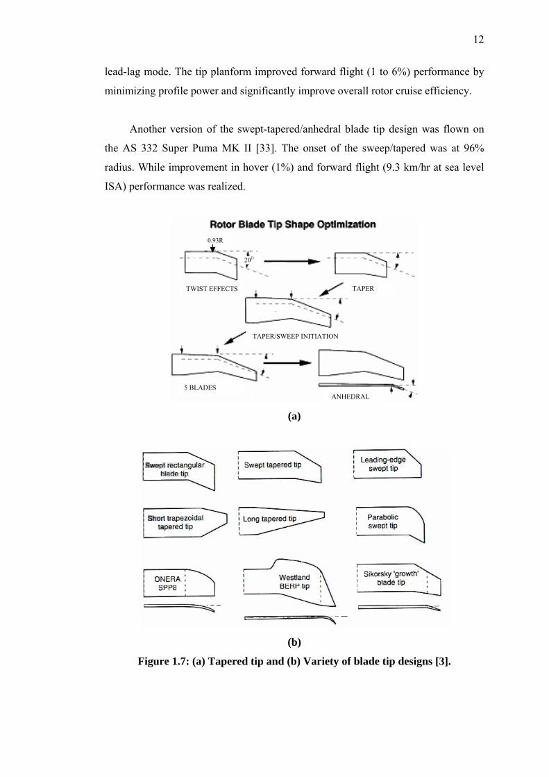
Figure 1.7 shows several of tapered blade tip designs which are the very successful
design to optimize the hovering flight. The result of a flight test of a swept back
parabolic tip on a Dauphin 365N was reported by Guillet, F and Phillipe, J.J. [32].
Additional weights were added at 45% radius for the dynamic tuning of the second
12
lead-lag mode. The tip planform improved forward flight (1 to 6%) performance by
minimizing profile power and significantly improve overall rotor cruise efficiency.
Another version of the swept-tapered/anhedral blade tip design was flown on
the AS 332 Super Puma MK II [33]. The onset of the sweep/tapered was at 96%
radius. While improvement in hover (1%) and forward flight (9.3 km/hr at sea level
ISA) performance was realized.
(a)
(b)
Figure 1.7: (a) Tapered tip and (b) Variety of blade tip designs [3].
0.93R
TWIST EFFECTS TAPER
TAPER/SWEEP INITIATION
5 BLADES ANHEDRAL
20O

13
The British Experimental Rotor Programme (BERP) blade was the result of
ten-year (1976-1986) aerodynamic research collaboration between Westland
helicopter and the Royal Aircraft Establishment. It was designed to meet the
conflicting aerodynamic requirements of advancing and retreating blade conditions,
either of which can limit the performance of the rotor in high forward flight. The
technical details of the BERP research program were described by Perry [34]. BERP
research paid off in 1986 when a GKN-Westland Super Lynx attained the world
absolute speed record for a conventional helicopter. As shown in Figure 1.8, the
BERP blade is distinctive because of its unique tip shape. The aerodynamic
improvements shown with the BERP rotor are the result of several innovations in
both airfoil design and tip shape design. The BERP blade uses a number of high
performance airfoils based on the RAE family. One of the most recognizable features
of the BERP blade is the use of high sweepback over the tip region, which is an
effective means of reducing compressibility effects and delaying their effect on the
rotor to a higher advanced ratio [35,36]. The BERP blade is specifically designed to
perform as a swept tip at high Mach numbers and low angles of attack, but it also
designed to operate at very high angle of attack without stalling.
25 degrees 30 degrees Figure 1.8: Example of CFD Results for the Flow Separation near the Notch
Region of A BERP Blade [27].
However, the world speed record was achieved as a result of the following four
accomplishments [45]:
1. Very good aerodynamic drag cleanup,
2. Water-methanol inject,

14
3. A reduction in engine tailpipe area in order to obtain a significant part of the
available engine power in the form of jet thrust, and
4. A novel main rotor blade tip called BERP tip.
In his report, Amer [45] has concluded that the BERP tip has only improved rotor
stall by about 5% and this tip was only a minor contribution to the speed record.
As previously discussed, one of the many problems confronting the helicopter
rotor aerodynamic is the compressibility effect that occurs at the advancing blade
side. The influences of compressibility are clear and potential to restrict the
helicopter forward flight speed. At high-speed forward flight, advancing side
blade(s) will involve with unsteady transonic, viscous, and highly non-linear
phenomena [31]. The flight envelope of a helicopter rotor is set by the
compressibility effects experienced by the advancing rotor blade and the retreating
blade dynamic stall. As the helicopter forward flight speed is increased, the
freestream velocity observed in the reference frame of the advancing blade is that of
the sum of the helicopter forward flight speed and the speed of the advancing blade.
At high cruise speeds, the freestream Mach number observed by the advancing blade
reaches levels where local supersonic zones on the surface of the rotor blade are
present. These regions usually terminate with a shock wave which causes a sudden
increase in wave drag. During the retreating phase, the blade incidence approaches
the stall angle, thus causing separation to occur on the upper surface of the blade
which leads to a loss of lift [37].
In most attempts, the blade planform modification has been applied on
reducing the compressibility effect [38-42]. Desopper et al [39] in their work have
observed that modification of the blade-tip planform may improve the aerodynamic
performance of the rotor by reducing the wave drag and the intensity of the transonic
flow that appear on the rectangular blade for fast forward flight speed. Several blade-
tip designs including rectangular, sweptback with constant sweep angle, swept
forward with constant sweep angle, sweptback-parabolic tip, FL5, RAE, PF2 and
rectangular with an anhedral tip shape have been tested in S2 Chalais-Meudon wind
tunnel (Figure 1.9). And as reported by Desopper, for almost all the advancing blade
side:

15
a) The intensity of the transonic flows is smaller on the PF2 tip when compared
to the straight tip,
b) The swept tip rotor has a lower drag and requires less power than the same
rotor with straight tip,
c) It is possible to decrease the intensity of the transonic flow for a large
azimuthal sector of the advancing side by using a 30 deg swept back tip, and
therefore it is possible to decrease the power needed to drive the rotor, and
d) The total performance measurements of the model rotor for rectangular and
sweptback parabolic tips shows that the PF2 tip has made possible a
significant reduction (5-8%) in the power required by the rotor.
Figure 1.9: Example of Rotor Blade Tip Tested in S2 Chalais-Meudon wind
tunnel [39].
Beside most of studies have focused on tapered, swept-tip, and parabolic
blade tip-shape, a computational fluid dynamic (CFD) analysis on more advanced
blade tip design which combined the several tip shapes and having a different value
of blade solidity was carried-out [43, 44]. From this study the Mach number normal
to the leading edge of the blade has reduced, thus allowing the rotor to attain a higher
advanced ratio before compressibility effect manifest as an increase in power
required. The use of different angle of sweep angle also affects tip vortex formation,
its location after has been trailed from the blade, and overall vortex structure.

16
1.2 HELICOPTER GENERAL DESCRIPTION
There are a many helicopter models that currently being operated in
Malaysia. In this study, two 5-seater helicopters under the same Federal Aviation
Regulation category 27 (FAR 27) have been chosen for design and analysis purposes.
The Eurocopter AS 355F2 (Eurocopter) and Agusta A 109A (Agusta) helicopter that
are respectively being utilized by Royal Malaysian Police Air Wing and by some
private operator (Fig. 1.10) were considered. The basic descriptions of these aircraft
are given in Table 1.0, and the selections of these aircraft are based on the following
criteria:
i. FAR 27 or JAR 27 category [50] for small rotorcraft,
ii. Comparable gross weight,
iii. Comparable installed powerplant performance, and
iv. Different in cruising speed performance.
Figure 1.10: (a) Agusta A 109A and (b) Eurocopter AS 355F2 helicopter.
Figure 1.11 depicts a 3-view drawing of 5-seater executive passenger
Eurocopter AS 355F2 helicopter. This helicopter is powered by 2 Allison 250C 20F
free turbine engines and installed in two independent fireproof bays. The main gear
box is modular design, i.e. consisting of subassemblies that can be replaced without
adjustment or special tooling, and without returning the gearbox to the factory. This
result in lower maintenance costs. The main gear box drive train of this aircraft
consists of planet pinions that are driven by the sun gear. They (planet pinions) in
turn drive the planet pinion carrier and thus the rotor mast at 394 rpm. This gearing
(a) (b)

17
system has gearing speed ratio of about 3.59 between sun gear and bevel ring gear,
and speed ratio of about 4.33 between gears in the planet pinion. With the engine
shaft rotational output of 6016 rpm, this gearing system will transfer the rotation
output of about 394 rpm to the main rotor shaft. This main rotor mast rotational
speed afterwards will then determine the helicopter cruising speed performance.
Table 1.0: General Description of Eurocopter [51] and Agusta [52] Helicopter.
DESCRIPTION Engines Rating
Eurocopter Agusta Take-off Power (kW) 2 x 313 2 x 313 Maximum Continuous Power, MCP (kW) 2x 276 2x 276
Main Rotor Airfoil Type (Inboard) Onera 209 Naca 23012 (Outboard) Onera 209 Naca 13006 Rotor Radius (m) 5.345 5.50 Chord 0.35 0.335 Shaft Rotational Speed (rad/s) 41.26 40.30 Twist Angle (deg) -9 -6 Number of Blades (N) 3 4 Blade Disc Area(m2) 89.75 95.0 Never Exceed Speed (km/hr) 278.0 296.0 Maximum Cruise Speed @ MCP (km/hr) 222.0 263.0
Weight Maximum Authorized Gross Weight (kg) 2540 2600 Empty Weight (kg) 1205 1418
As listed in Table 1.0, the most obvious physical different between Agusta
and Eurocopter is in the number of blades. They have 4 and 3 blades respectively.
The effect of using the different number of blade on forward flight performance has
become the interest of this study. In term of blade airfoil profile, Agusta helicopter
uses a combination of different airfoils at inboard and at outboard of blade. The rotor
that uses single airfoil on the entire span of blade cannot meet all the various
aerodynamic requirement. This is because the angle of attack and Mach number of
blade element vary continuously along the blade span. Unlike Agusta, Eurocopter
using a single ONERA 209 airfoil with tab at the trailing edge (Figure 1.12). A
general discussion about ONERA 209 airfoil will be given in subsection 2.5.1.2.

18
Figure 1.11: 3-view of Eurocopter AS 355F2 Helicopter

19
Figure 1.12: ONERA 209 Airfoil, t/c = 9% [51]
Both the helicopter’s main-rotor blades consist of the negative (nose down)
twist. The purpose of negative twist of the blade here is to redistribute the lift over
the blade and help reduce the induced power. The proper use of blade twist can
significantly improve hover figure-of-merit. In forward flight however, the rotor with
a high nose-down blade twist may suffer some performance loss. This is because of
the reduced angle of attack on the tip of the advancing blade resulting in a loss of
rotor thrust and propulsive force. In this study, the blade twist value and blade profile
of the new rotor design will be kept the same as the current blade design. However,
the attentiveness of this study is given to the methods of increasing the number of
blade and optimizing the blade and rotor size due to increasing in the number of
blade.
Another significant different between Agusta and Eurocopter that may
contribute to the better forward flight speed is the use of different type of landing
gear. The use of different type of landing gear may give either an advantage or a
disadvantage to the helicopter forward speed performance. It may cause either
increasing or decreasing in the aircraft parasite drag. Usually, the low fuselage drag
is required in the design of helicopter for improved performance. The drag of a
helicopter fuselage may be up to one order of magnitude higher than that of fixed-
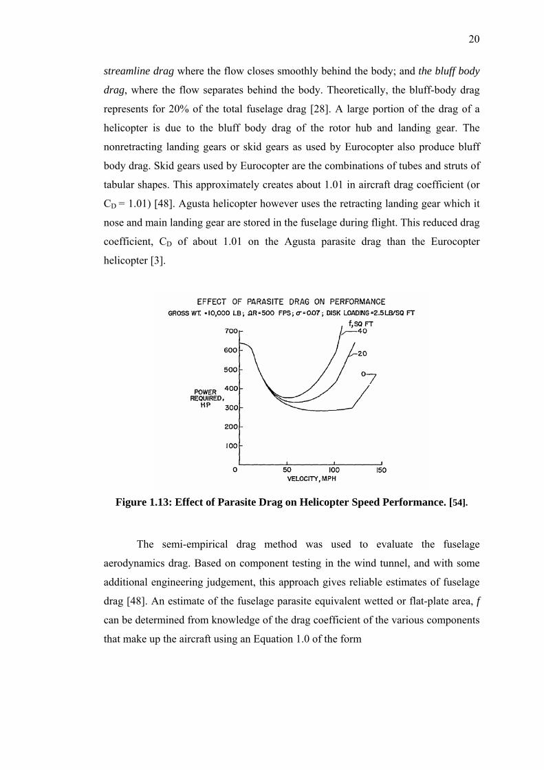
wing aircraft of the same gross weight. Figure 1.13 depicts the effect of parasite drag
on helicopter performance. For a helicopter, there are 2 types of parasite drag: the
Tab
20
streamline drag where the flow closes smoothly behind the body; and the bluff body
drag, where the flow separates behind the body. Theoretically, the bluff-body drag
represents for 20% of the total fuselage drag [28]. A large portion of the drag of a
helicopter is due to the bluff body drag of the rotor hub and landing gear. The
nonretracting landing gears or skid gears as used by Eurocopter also produce bluff
body drag. Skid gears used by Eurocopter are the combinations of tubes and struts of
tabular shapes. This approximately creates about 1.01 in aircraft drag coefficient (or
CD = 1.01) [48]. Agusta helicopter however uses the retracting landing gear which it
nose and main landing gear are stored in the fuselage during flight. This reduced drag
coefficient, CD of about 1.01 on the Agusta parasite drag than the Eurocopter
helicopter [3].
Figure 1.13: Effect of Parasite Drag on Helicopter Speed Performance. [54].
The semi-empirical drag method was used to evaluate the fuselage
aerodynamics drag. Based on component testing in the wind tunnel, and with some
additional engineering judgement, this approach gives reliable estimates of fuselage
drag [48]. An estimate of the fuselage parasite equivalent wetted or flat-plate area, f
can be determined from knowledge of the drag coefficient of the various components
that make up the aircraft using an Equation 1.0 of the form

21
∑=n
nD SCfn
(1.0)
1.3 HELICOPTER SPEED LIMITATION
As for fixed-wing aircraft, the maximum speed of a helicopter in level flight
is limited by the power available, but with a rotary wing there are a number of other
speed limitations as well. This includes the stall, compressibility, and aeroelastic
stability effect. The primary limitation with many current designs is retreating blade
stall, which at high speed produces an increase in the rotor and control system loads
and helicopter vibration, severe enough to limit the flight speed. The result of these
limitations is that the design cruise speed of the pure helicopter is generally between
277.8 and 370.4 km/hr with current technology. To achieve a higher forward speed
requires either an improvement in rotor and fuselage aerodynamic or a significant
change in the helicopter configuration.
The absolute maximum level flight speed is the speed at which the power
required equals the maximum power available. At high speed the principle power
loss is the parasite power. To increase the power-limited speed requires an increase
in the installed power of the helicopter or a reduction in the hub and body drag.
Because of the parasite power is proportional to cube of flying speed, V3, a
substantial change in drag or installed power is required to noticeably influence the
helicopter speed. The rotor profile power also shows a sharp increase at some high
speed as a result of stall and compressibility effects.
A measure of stall effects on the rotor is the ratio of the thrust coefficient to
solidity σTC , which represents the mean lift coefficient of the blade. In hover, quite
high values of σTC can be achieves before the profile power increase due to stall is
encountered. In forward flight, however, the angle of attack increases at the
retreating side of the disc to maintain the same loading as on the advancing side,
hence the stall is encountered at significantly lower values σTC .

22
The maximum advanced ratio at which the helicopter may be operated
depends on several factors. As advanced ratio µ, increases, the aeroelastic stability of
the blade motion decreases, the blade and control loads increase because of the
asymmetry of the flow, and the aerodynamic efficiency and propulsive force
capability of the rotor decrease. Retreating blade stall often constitutes the primary
restriction on µ. For a specified maximum advanced ratio, the rotor tip speed must
be increased to obtain a high forward speed of the helicopter. However,
compressibility limits the possible tip speed and thus limits the helicopter speed.
1.4 OBJECTIVE
To study the feasibility of improving the 5-seater helicopter forward flight speed
through the increase in the number of blade, different blade size and engine sizing.
1.5 SCOPE OF RESEARCH
The scopes of this project were established as follows:
i. To determine the performance of the existing helicopter rotor.
ii. To study the possible factor (increase in the number of blade, different blade
size and engine sizing) that could improve the existing flight speed.
iii. To determine the speed increment.
1.6 RESEARCH DESIGN
The research design comprises of:
i. Preliminary study to select the appropriate and available helicopter.
ii. Theoretical analysis by using closed-form equation from blade element
theory [48].
iii. CFD analysis by using Fluent Inc. and Gambit software for flow
simulation and grid generation.

97
REFERENCES
[1] Warner, E. P. (1922). “The Prospect of the Helicopter.” NACA TM 107. [2] Hooper, W.E. (1987). “Technology for Advanced Helicopter.” SAE Paper No.
872370: 6.1668-6.1675. [3] Leishman, J.G. (2001). “Principles of Helicopter Aerodynamics.” United
Kingdom: Cambridge University Press. [4] Ford, T. (1997). “Advanced in Rotorcraft.” Aircraft Engineering and
Aerospace Technology. 69(5): pp 447-452. [5] Johnson, W. (1980). “Helicopter Theory.” New Jersey: Princeton University
Press. [6] Gessow, A. (1986). “Understanding and Predicting Helicopter Behaviour-Then
and Now.” Journal of American Helicopter Society 31(1): 3-28. [7] Caradona, F.X, and Philippe, J.J. (1978). “The Flow Over A Helicopter Blade
Tip In The Transonic Regime.” Vertica, (2)1, pp 43-60. [8] Bailey, F.J., Jr. and Gustafson, F.B. (1939). “Observations in Flight of the
Region of Stalled Flow over the Blades of an Autogyro Rotor.” NACA TN No. 741.
[9] McCroskey, W.J., McAlister, K.W., Carr, L.W., and Pucci, S.L. (1982). “An
Experiment Study of Dynamic Stall on Advanced Airfoil Section.” NASA TM-84245; Vol: 1, 2, 3.
[10] McCroskey, W.J. and Fisher, R. k., Jr. (1972). “Detailed Aerodynamic
Measurements on a Model Rotor in the Blade Stall Regime.” Journal of American Helicopter Society 17(1): 20-30.
[11] Bousman, W.G. (2002). “Airfoil Design and Rotorcraft Performance.”
Proceeding of the 58th Annual American Helicopter Society Forum. [12] Newman, S. (1997). “The Compound helicopter Configuration and the
Helicopter Speed trap”. Aircraft Engineering and Aerospace Technology. 69(5): pp 407-413.
98
[13] Rafi Yoeli (2002). “Ducted Fan Utility Vehicles and Other Flying Cars.” presented to The American Institute of Aeronautics and Astronautics, November.
[14] Chana, W. F. and Sullivan, T. M. (1992). “The Tilt-Wing Advantage-For High
Speed VSTOL Aircraft.” SAE Paper No 921911: pp 1535-1543. [15] Fradenburgh, E.A. (1991). “The High Speed Challenge for Rotary Wing
Aircraft”. SAE Paper No. 911974: pp 1969-1987. [16] Jimmy, C.T., Dimitri, N.M. and Schrage, D.P. (1997). “A Comparative
Assessment of High Speed Rotorcraft Concept (HSRC): Reaction Driven Stopped Rotor/Wing and Variable Diameter Tiltrotor”.
[17] Geissler, W., Sobieczky, H., and Trenker, M. (2000). “New Rotor Airfoil
Design Procedure for Unsteady Flow Control”. Duetches Zentrum für Luft-und Raumfahrt e.V., Institut für Strömungsmechanik, Bunsenstr. 10 D-37073 Göttingen, Germany.
[18] Geissler, W., and Trenker, M. (2002). “Numerical Investigation of Dynamic
Stall Control by a Nose-Drooping Device”. Presented at the American Helicopter Society Aerodynamics, Acoustics, and Test and Evaluation Technical Specialist Meeting.
[19] Chandrasekhara, M. S. and Carr, L. W. (1998). “Unsteady stall Control using
Dynamically Deforming Airfoils,” AIAA Journal, 36(10). [20] Lorber, P., McCormick, D., Anderson, T., Wake, B., MacMartin, D., Pollack,
M., Corke, T. and Bruer, K. (2000). “Rotorcraft Retreating Blade Stall Control”. AIAA 2000-2475.
[21] McCormick, D.C, Lozyniak , S. A., MacMartin, D. G., and Lorber, P. F.
(2001). “COMPACT, HIGH-POWER BOUNDARY LAYER SEPARATION CONTROL ACTUATION DEVELOPMENT”. Proceedings of ASME FEDSM’01. Paper No. 18279.
[22] Seifert, A., Bachar, T., Koss, D., Shepshelovich, M. and Wygnanski, I. (1993).
“Oscillatory Blowing - A Tool to delay Boundary Layer Separation,” AIAA Journal, 31(11), pp. 2052-2060.
[23] Magill, J., Bachmann, M., Rixon, G., and McManus, K. (2001). “Dynamic Stall
Control Using a Model-Based Observer”. AIAA 2001-0251. [24] Carr, L. W. and McAlister, K. W. (1983). “The Effects of Leading Edge Slat on
the Dynamic Stall of an oscillating Airfoil,” AIAA Paper 85-2533. [25] Tuncer, I. And Sankar, L. N. (1994). “Unsteady Aerodynamic Characteristics
of a Dual-Element Airfoil,” Journal of Aircraft, 31(3).

99
[26] Bangalore, A. and Sankar, L. N. (1996). “Numerical Analysis of Aerodynamic Performance of Rotors with Leading Edge Slats,” Journal of Computational Mechanics, Vol. 17, pp. 335-342.
[27] Duque, Earl P. N. (1992). “A Numerical Analysis of the British Experimental
Rotor Program Blade”. Journal of American Helicopter Society, 37(1): pp 46-54.
[28] Leishman, J.G. (1989). “Modeling Sweep effect on Dynamic Stall”. Journal of
American Helicopter Society, 34(3): pp 18-29. [29] Amer, K.B. (1989). “High-Speed Rotor Aerodynamics”. Journal of American
Helicopter Society, Technical Note. 34(1): pp 63. [30] Perry, F.J. (1989). “The Contribution of Planform Area to the Performance of
the BERP Rotor”. Journal of American Helicopter Society, 34(1). [31] Preiur, J., Lafon, P., Caplot, M., Desopper, A. (1989). “Aerodynamics and
Acoustic of Rectangular and Swept Rotor Blade Tips”. Journal of American Helicopter Society, 34(1): pp 42-51.
[32] Guillet, F. and Philippe, J.J. (1984) “Flight Test of a Swept Back Parabolic Tip
On A Dauphin 365N.” 10th European Rotorcraft Forum. [33] Gullet, A., Allongue, M., Philippe, J.J., and Desopper, A. (1989). “Performance
And Aerodynamic Development of The Super Puma MK II Main Rotor With New SPP8 Blade Design.” 15th European Rotorcraft Forum.
[34] Perry, F.J. (1987). “The Aerodynamics of the World Speed Record”. Presented
at the 43rd Annual Forum of the American Helicopter Society, St. Louis.
[35] Brocklehurst, A., Beedy, J., Barakos, G., Badcock, K., & Richards, B. E. “Experimental and CFD Investigation of Helicopter BERP Tip Aerodynamics.”
[36] Brocklehurst, A. and Duque, E. P. N. (1990). “Experimental and Numerical Study of the British Experimental Rotor Programme Blade.” AIAA 8th Applied Aerodynamics Conference, AIAA-90-3008.
[37] Siva K. Nadarajah and Jameson, A. (2002). “Optimal Control of Unsteady
Flows Using a Time Accurate Method.” AIAA Journal Paper 2002-5436. [38] Chee Tung, Caradonna, F.X., and Johnson, W. (1984). “The Prediction of
Transonic Flows on Advancing Rotor.” Presented at the 40th Annual Forum of the American Helicopter Society, Arlington.
[39] Desopper, A., Lafon, P., Ceroni, P., and Philippe, J.J. (1986). ‘Ten Years Of
Rotor Flow Studies at ONERA.’ Presented at the 42nd Annual Forum of the American Helicopter Society, Washington.

100
[40] Althoff, S.L. (1989). “Effect of tip speed on rotor inflow.” Journal of American Helicopter Society, 34(4): pp 18-27.
[41] McCroskey, W.J., Beader, J.D., and Bridgeman, J.O. (1985). “Calculation of
Helicopter Airfoil Characteristic for High Tip-Speed Applications.” Journal of American Helicopter Society, 31(2): pp 3-9.
[42] Walsh, J.L., Bingham, G.J., and Riley, M.F. (1985). “Optimization Method
Applied to the Aerodynamic Design of Helicopter Rotor Blades.” Journal of American Helicopter Society, 32(4): Pp 39-44.
[43] Aoyama, T., Kawachi, K., and Saito, S. (1995). “Effect of Blade-Tip Planform
on Shock Wave of Advancing Helicopter Blade.” Journal of Aircraft, 32(5): Pp. 955-961.
[44] Aoyama, T., Saito, S., and Kawachi, K. (1992). “Unsteady Calculation for
Flowfield of Helicopter Rotor with Various Tip Shapes.” Proceeding of the 18th European Rotorcraft Forum, Avignon: Pp. B03.1-B03.12.
[45] Amer, K.B. (1989). “High Speed Rotor Aerodynamics”, Technical Note,
Journal of American Helicopter Society, 34(1): pp 63. [46] Bramwell, A.R.S., Done, G., and Balmford, D. (2001). “Bramwell’s Helicopter
Dynamics”. London: Butterworth Heinemann. [47] Raletz, R. (1988). “Basic Theory of the Helicopter (Pictorial Initiation)”.
France: CEPADUES-Edition. [48] Prouty, R.W. (Year). “Helicopter performance, Stability and Control”. PWS
Engineering, Boston. [49] Fay, G. (2001). “Derivation of the Aerodynamic Forces for the Mesicopter
Simulation”. [50] FAR 27 for Small Helicopter (2001) [51] Twinstar AS 355 Instruction Manual, Aerospatiale. Issue 1986. [52] http://www.agustawestland.com. Access on 9th March 2005. [53] A.A. Wahab and N.A.R. Nik Mohd (2004). “The Effect of Blade Solidity on
Helicopter Cruising Speed”. Published at The Malaysian Science and Technology Congress (MSTC), Kuala Lumpur.
[54] Barrington, R. D. (1954). “Reduction of Helicopter Parasite Drag”, NACA TN
3234. [55] Fluent Inc. Manual (2003).

101
[56] Versteeg, H.K. and Malalasekera, W. (1995). “An Introduction to Computational Fluid Dynamics – The Finite volume Method”, Longman, Malaysia.
[57] Caradonna, F. X. and Isom, M. P. (1972). “Subsonic and Transonic Potential
Flow over Helicopter Rotor Blades”, AIAA Journal, No. 12, pp. 1606-1612. [58] Chang, I. C.(1984). “Transonic Flow Analysis for Rotors”, NASA TP 2375. [59] FLUENT News 2002 (11)2, pp: s9 [60] Xu, M., Mamou, M. and Khalid, M. (2002). “Numerical Investigation of
Turbulent Flow Past a Four-Bladed Helicopter Rotor Using k-ω SST Model”, The 10th Annual Conference of CFD Society of Canada, Windsor.
[61] Wake, B. E. and Baeder, F. D.(1996). “Evaluation of a Navier-Stokes Analysis
Method for Hover Performance Prediction,” Journal of the American Helicopter Society, Vol. 41, No. 1, pp. 1-17.
[62] Beaumier, P., Pahlke, K., and Celli, E. (2000). “Navier- Stokes Prediction of
Helicopter Rotor Performance in Hover Including Aero-Elastic Effects,” American Helicopter Society 56th Annual Forum, Virginia Beach, VA.
[63] Pomin, H. and Wagner, S. (2001). “Navier-Stokes Analysis of Helicopter Rotor
Aerodynamics in Hover and Forward Flight,” AIAA Paper 2001-0998, 39th Aerospace Sciences Meeting and Exhibit.
[64] Strawn, R. C. and Djomehri, M. J. (2001). “Computational Modeling of
Hovering Rotor and Wake Aerodynamics,” American Helicopter Society 57th Annual Forum, Washington, DC.
[65] Sides, J., Pahlke, K. and Costes, M. (2001). “Numerical Simulation of Flow
Around Helicopter at DLR and ONERA”, Editions Scientifiques et Medicales Elsevier.
[66] H. van der Ven and O.J. Boelens (2003). “Towards Affordable CFD
Simulations Of Rotors In Forward Flight”, DLR, Present at the 59th American Helicopter Society Forum,Phoenix, Arizona, USA.