feasibility report use of mir spectroscopy for optimisation of … i queens university... ·...
TRANSCRIPT

Feasibility Report
Use of MIR Spectroscopy for
Optimisation of Biogas Plants
A feasibility report from the ‘Driving Innovation in AD’ programme which looks at the use of MIR spectroscopy for optimisation of biogas plants
Project code: OIN001-407 Research date: March – June 2012 Date: October 2012

WRAP’s vision is a world without waste, where resources are used sustainably. We work with businesses, individuals and communities to help them reap the benefits of reducing waste, developing sustainable products and using resources in an efficient way. Find out more at www.wrap.org.uk Document reference: [e.g. WRAP, 2006, Report Name (WRAP Project TYR009-19. Report prepared by…..Banbury, WRAP]
Written by: Simon Murray & Elaine Groom, QUESTOR Centre, Queen’s University Belfast; Christian Wolf, Gummersbach Environmental Computing Centre, Cologne University of Applied Science Project Partners: agriAD, EnviTec Biogas UK Ltd, Fibre Photonics & Cologne University of Applied Sciences
Front cover photography:
While we have tried to make sure this report is accurate, we cannot accept responsibility or be held legally responsible for any loss or damage arising out of or in
connection with this information being inaccurate, incomplete or misleading. This material is copyrighted. You can copy it free of charge as long as the material is
accurate and not used in a misleading context. You must identify the source of the material and acknowledge our copyright. You must not use material to endorse or
suggest we have endorsed a commercial product or service. For more details please see our terms and conditions on our website at www.wrap.org.uk

Use of MIR Spectroscopy for Optimisation of Biogas Plants 1
Abstract
MIR spectroscopy is an established technique which has process monitoring applications in the chemical and pharmaceutical industries. Previous attempts to utilise the technology for monitoring of AD plants were of limited success, with operation hindered by severe clogging of the probe. Novel fittings, which allow a probe to be withdrawn from the process fluid, cleaned and recalibrated in situ have now been developed to combat this clogging problem. This has allowed a spectroscopic probe to be used successfully in lab scale digesters for real time measurement of VFA concentration, a key parameter to the stability of AD plants. This project will demonstrate the technology at a farm scale AD plant for the first time. Both real-time measurements of VFA concentrations and parameters currently measured by plant operators will be available, leading to state-of-the-art monitoring and control of the AD plant. With the improved monitoring that this probe will deliver, it is hoped to realise a 10% increase in biogas production without compromising the stability of the process. This will deliver both economic and environmental benefits.

Use of MIR Spectroscopy for Optimisation of Biogas Plants 2
Executive summary
The reliable measurement of relevant process parameters is vital to the control and optimisation of industrial processes, however, state-of-the-art control of anaerobic digestion facilities currently lacks on-line measurement for some the key parameters. Monitoring of gas production and composition, and digester pH are supplemented by off-line measurements, of which one of the most important for monitoring of process stability is VFA concentrations. A cost-effective system that allows frequent and reliable on-line monitoring of VFAs has not previously been available, however, this capability would have direct monetary benefits for plant operators, by enabling an early indication of process upsets. More importantly, to avoid breakdowns due to high VFA concentrations, most AD plants are operated in a ‘safe zone’ of low organic loading rates where operation is more stable but biogas yields are lower. Despite this obvious benefit, instrumentation and control at full scale biogas plants is in its infancy. Even in Germany, where the biogas production industry is much more mature than it is in the U.K., only 70% of all biogas plants have measurement systems, and then only for the biogas production rate and biogas quality. Online measurement of parameters requiring more sophisticated equipment, such as pH, redox potential and VFA content, is available at less than 5% of plants. More widespread adoption of measurement devices for these parameters is limited by cost and reliability of available systems. Over the last decade, advances in UV and visible light (UV/vis), near-infrared (NIR) and mid-infrared (MIR) spectroscopy have allowed some of the key parameters in digester operation to be measured indirectly. This project aims to demonstrate the potential of a novel MIR-spectroscopy system for real time monitoring of a biogas plant. The MIR probe in this system comes with a fully-automated cleaning and recalibration system. This system has two advantages. On the one hand, organic acids have very distinctive reflection spectra in the MIR-spectrum, which allows for a more universal calibration and on the other hand problems of clogging and recalibration are automatically mitigated. The MIR-probe will be installed at a farm-scale AD facility in Northern Ireland, calibrated for various parameters with an appropriate sampling and laboratory analysis regime, and used for long term monitoring of digester conditions. Deployment of this technology in the biogas industry will allow safe operation of existing assets at higher organic loading rates, delivering increased biogas production and realising economic and environmental benefits for plant operators. Incorporation of the technology into new projects will allow the same performance to be obtained from smaller assets by operating them closer to their capacity.

Use of MIR Spectroscopy for Optimisation of Biogas Plants 3
Contents
1.0 Introduction and background ....................................................................... 8 1.1 Company/consortium ................................................................................. 8 1.2 Introduction to your technology .................................................................. 9 1.3 Proposal (technology/concept) background ................................................ 10
2.0 Project Objectives ...................................................................................... 12 2.1 What did you set out to achieve from the feasibility study and what are your aims for the demonstration ................................................................................. 12 2.2 How does the feasibility report and the proposed demonstration project meet the desired outcomes of the ‘Driving Innovation’ programme ................................. 13
3.0 State of technology .................................................................................... 14 3.1 Development history of the technology ...................................................... 14 3.2 Previous use/evidence to support the use of your technology from other countries, sectors or industries where applicable ................................................... 15 3.3 c. Previous tests ie. desk-based studies, lab-scale, on the ground ................ 15 3.4 Verification of the MIR probe cleaning regime ............................................. 20
4.0 Legislation .................................................................................................. 27 4.1 Identification of the relevant regulations and legislation which will apply to the development and/or installation of the technology, identification and mitigation of risks relating to these ......................................................................................... 27
5.0 Detailed technical appraisal of technology ................................................. 30 5.1 Theory/process behind the technology ....................................................... 30 5.2 Operational parameters ............................................................................ 33 5.3 Comparison with ‘business as usual’ .......................................................... 33 5.4 Range ..................................................................................................... 34 5.5 Life cycle of technology ............................................................................ 34 5.6 Risk Analysis ............................................................................................ 35 5.7 References .............................................................................................. 35
6.0 Economic/Cost Benefit Analysis ................................................................. 36 6.1 Appraisal of Cost to industry/facilities including capex and opex and other associated financial benefits ................................................................................ 36 6.2 Comparative Cost Benefit Analysis versus ‘business as usual’ ....................... 36
7.0 Overall Environmental Impacts .................................................................. 41 7.1 References .............................................................................................. 42
8.0 PHASE 2 DEMONSTRATION ........................................................................ 43 8.1 Methodology for demonstration ................................................................. 43 8.2 Include any statements confirming/evidencing the selection and securing of sites, stakeholders, personnel and contractors ...................................................... 45
9.0 Complete and detailed project timescale ................................................... 46 9.1 Project Financing ..................................................................................... 46 9.2 Operation ................................................................................................ 46 9.3 Monitoring and evaluation ......................................................................... 46 9.4 Decommissioning ..................................................................................... 47
10.0 Project milestones ...................................................................................... 49 11.0 Commercialisation of technology post demonstration ............................... 50
11.1 Plan for approaching the market................................................................ 50 11.2 Standards and regulation .......................................................................... 50 11.3 Anticipated size of the market to be approached ......................................... 50 11.4 Projections for industry uptake in year 1, 2, 5, 10 etc .................................. 51 11.5 Companies likely to deliver the technology ................................................. 51
12.0 Key personnel ............................................................................................. 53 13.0 Evaluation and monitoring for the purpose of WRAP reporting ................. 55

Use of MIR Spectroscopy for Optimisation of Biogas Plants 4
14.0 Health and Safety ....................................................................................... 55 15.0 Conclusion .................................................................................................. 55

Use of MIR Spectroscopy for Optimisation of Biogas Plants 5
List of Figures
Figure 1: Real time reaction monitoring ........................................................................ 10 Figure 2: a) MIR probe from fibre photonics, b) Ceramat installation fitting manufactured by Knick ........................................................................................................................... 14 Figure 3: Comparison of the MIR spectra from acetic acid. MIR probe (left), NIST spectra database (right) ........................................................................................................... 16 Figure 4: Comparison of the MIR spectra from propionic acid. MIR probe (left), NIST spectra database (right) ................................................................................................ 16 Figure 5: Comparison of the MIR spectra from butanoic acid. MIR probe (left), NIST spectra database (right) ........................................................................................................... 17 Figure 6: Comparison of the MIR spectra from valeric acid. MIR probe (left), NIST spectra database (right) ........................................................................................................... 17 Figure 7: Calibration line for acetic acid at 1722 cm-1 ..................................................... 18 Figure 8: Calibration line for acetic acid at 1392 cm-1 ..................................................... 18 Figure 9: Calibration line for acetic acid at 1276 cm-1 ..................................................... 19 Figure 10: Cleaning of the MIR probe after the measurement of milk (3.5% fat) .............. 21 Figure 11: Cleaning of the MIR probe after the measurement of flour type 405 ............... 22 Figure 12: Cleaning of the MIR probe after the measurement of sunflower oil ................. 23 Figure 13: Cleaning of the MIR probe after the measurement of a mixture of milk, flour and sunflower oil ................................................................................................................ 24 Figure 14: Cleaning of the MIR probe after the measurement of digestate from an industrial biogas plant ................................................................................................................. 25 Figure 15: Example of a transmission spectrum for Formaldehyde over the MIR-range. .... 30 Figure 16: Principle of MIR online-measurement system ................................................ 30 Figure 17: Diamond-tipped ATR probe for MIR .............................................................. 31 Figure 18: MIR-probe suffering from severe clogging and fouling before and after cleaning .................................................................................................................................. 32 Figure 20: Complete MIR online-measurement system for AD processes ......................... 33 Figure 21: Gantt Chart .................................................................................................. 48 Figure 22: Commercialisation Strategy ......................................................................... 51 Figure 23: Site location (Drumnahare marked as ‘A’) ..................................................... 56 Figure 24: Plant layout at Drumnahare AD facility ......................................................... 57 Figure 25: Envitec process diagram .............................................................................. 57 Figure 26: Kreis-Dissolver............................................................................................ 59 Figure 27: Example chromatograph for VFA determination ............................................. 63

Use of MIR Spectroscopy for Optimisation of Biogas Plants 6
List of Tables
Table 1: Project outcomes in support of DIAD programme goals ..................................... 13
Table 2: Calibration results for acetic, butanoic, propionic and iso butanoic acid with
characteristic wavenumbers and corresponding correlation coefficients ............................. 19
Table 3: Risk Analysis .................................................................................................. 35
Table 4: Cost benefit of project – Scenario A: 10% increase in biogas production due to
increased feedstock loading .......................................................................................... 38
Table 5: Cost benefit of project – Scenario B – 10% increase in biogas production to due
increased biogas yield ................................................................................................... 39
Table 6: Environmental benefit of technology ................................................................ 41
Table 7: Simplified Life Cycle Assessment ...................................................................... 41
Table 8: Project Partnership ......................................................................................... 45
Table 9: Parameters to be monitored during demonstration ............................................ 46
Table 10: Project workpackages and estimated completion dates .................................... 49
Table 11: Project milestones and estimated dates ......................................................... 49
Table 17: Results table for pH measurement ................................................................. 60
Table 18: Results table for Redox potential measurement .............................................. 61
Table 19: Results table for Total Ammonia measurement ............................................... 61
Table 20: Results table for Total and Volatile Solids Content ........................................... 62
Table 21: Results table for VFA determination ............................................................... 63
Table 22: Results table for FOS/TAC determination ........................................................ 64

Use of MIR Spectroscopy for Optimisation of Biogas Plants 7
Glossary
ABPs Animal By-Products
AD Anaerobic Digestion
ANN Artificial Neural Networks
ATR Attenuated Total Reflectance
CHP Combined Heat and Power
CIR Chalcogenide glass Infra-red
COD Chemical Oxygen Demand
COSHH Control of Substances Hazardous to Health
CUAS Cologne University of Applied Sciences
DARD Department of Agriculture and Rural Development
DECC Department of Energy and Climate Change
FOS Volatile Organic Acids (Flüchtigen Organischen Säuren) GC Gas Chromatograph
IP Intellectual Property
IR Infra-red
ISA Ionic Strength Adjustor
KTP Knowledge Transfer Partnership
LEC Levy Exemption Certificate
MIR Mid Infra-Red
NIEA Northern Ireland Environment Agency
NIR Near Infra-Red
NIST National Institute of Standards and Technology
NNFCC National Non-Food Crops Centre
OPC Open Process Control
OPEX Operational Expenses
PIR Polycrystalline Infra-red
PLS Partial Least Squares regression
PPA Power Purchase Agreement
RF Random Forest
ROC Renewable Obligation Certificate
ROCs Renewable Obligation Certificates
SCADA Supervisory Control and Data Acquisition
SME Small to Medium Enterprise
TAC Buffer Capacity (Titre Alcalimétrique Complet) TOC Total Organic Carbon
UV Ultraviolet (light)
VFA Volatile Fatty Acids
vis Visible (light)
WP Work Package

Use of MIR Spectroscopy for Optimisation of Biogas Plants 8
1.0 Introduction and background 1.1 Company/consortium This is a collaborative project between three SMEs and two university research groups. It will be led by the QUESTOR Centre, a university research centre at Queen’s University Belfast. The QUESTOR Centre is an industrially led, university research centre which carries out applied environmental research in four areas of interest: Water and Wastewater Treatment; Sensors for Environmental Monitoring; Soil and Groundwater Remediation and Energy from Biomass. The Centre has significant experience in the area of anaerobic digestion. Recent research by staff from the Centre includes GreenGrass, a four year collaboration with Teagasc and University College Cork addressing the utilisation of grass resources in Ireland for the production of biogas. The Centre has also collaborated directly with industry through the completion of four technology transfer projects (3 KTPs, 1 North-South Ireland Cooperation FUSION Project) focussing on different aspects of anaerobic digestion, and was one of 5 groups funded by Scottish Enterprise as part of its Seaweed Anaerobic Digestion Programme. The Centre also provides laboratory testing services to an extensive client base throughout the water, waste, wastewater, and renewable energy sectors on a consultancy basis. These facilities will be made available to the project. Access to additional testing facilities in other units of the university can also be arranged if required. Other partners in the project are an Anaerobic Digestion (AD) facility owner, agriAD Ltd. and two technology providers, EnviTec Biogas UK Ltd and Fibre Photonics Ltd. agri AD Ltd is a development company whose primary business is the development of on-farm Anaerobic Digestion plants in partnership with the farm owners. The farm owner provides the site for an AD plant, the AD feedstock (typically grass silage and animal manure) and operates the plant. agriAD provide project funding, AD technology, project development and process management, biological support and plant maintenance. Currently, agriAD have full planning permission for a 500 kW AD plant which will be located at a farm near Banbridge, County Down, Northern Ireland, owned by the directors of agriAD Ltd. The first phase of this plant, which will generate 255 kW of electricity, is currently under construction and will be operational in early 2013. This plant will host the site trials as part of the main research project. The company are in on-going discussions regarding over 50 other potential AD facilities, 7 of which are currently in planning. EnviTec Biogas UK Ltd is the UK division of EnviTec Biogas AG. EnviTec Biogas AG covers the entire value chain for the production of biogas – including the planning and turnkey construction of biogas plants and their commissioning. The company provides the biological and technical services to support plant operation. In addition EnviTec also operates more than 40 of its own biogas plants. In 2011 EnviTec Biogas expanded operations into processed bio-methane and the trading of green gas and green electricity. The company is represented in 15 countries throughout Europe as well as in India. EnviTec has delivered more than 500 biogas plants with an installed capacity in excess of 250 MW.

Use of MIR Spectroscopy for Optimisation of Biogas Plants 9
EnviTec Biogas UK (ETUK) was formed 4 years ago and is a Joint Venture between EnviTec Biogas AG and ARM Buildings Ltd, a long established livestock buildings company based in Rugeley, Staffordshire. ETUK’s objective is to supply and install ET biogas plants in the UK and Ireland. ETUK now has 6 plants operational or near to completion. The first plant is 500 kW, runs on food waste and is located in South Wales. The other 5 are farm-based facilities utilising farm derived crops, all located in England and comprising of 2 at 500 kW and 3 at 1 MW installed capacity. EnviTec Biogas UK is developing the market for biogas plants in Northern Ireland under a collaboration agreement with agriAD. Fibre Photonics Ltd was established in October 2006 and is based in Livingston, Scotland. The company specialises in the development and manufacture of mid infrared fibre optic materials for light delivery in industrial and avionic applications, and also chemical sensing in biotech, pharma, chemicals and food and drink applications. Specifically relating to chemical sensing, the company produces a variety of fibre optic based attenuated total reflectance (ATR) immersion probes that can operate in either the visible, near infrared or mid infrared regions. The company has implemented lean manufacturing principles throughout its fibre optic production facility and has the ability to investigate the feasibility of providing reaction monitoring through the development of an analytical chemistry laboratory. A German university research centre, the Gummersbach Environmental Computing Center (GECO►C) at the Cologne University of Applied Sciences (CUAS), will provide world class expertise on optical sensors as well as their calibration and maintenance on a sub-contracting basis. GECO►C has an existing working relationship with Fibre Photonics’ German partners, A.R.T. Photonics, and has experience working with the technology which will be used in the main research project. 1.2 Introduction to your technology Reliable measurement of relevant process parameters is vital to the control and optimisation of industrial processes. In most biogas plants, there is normally little real-time monitoring of the key biological and chemical processes underpinning performance. Control loops are usually limited to temperature control, despite the digestion process being sensitive to changes not only in temperature but also to other parameters such as pH, carbon buffer (alkalinity), organic acid concentration, ammonia concentration and substrate composition. For the complete control and optimisation of AD processes a measurement of all of these parameters is required. On-line monitoring allows early detection and warning of process disturbances to prevent breakdowns and consequently a system with this capability would have direct benefits for plant operators in terms of reduction of risk. More importantly, to avoid breakdowns, most plants are operated in a ‘safe zone’ of low organic loading rates where operation is more stable but biogas yields are lower. Improved monitoring may allow the AD plant to operate at higher organic loading rates. Despite this obvious benefit, instrumentation and control at full scale biogas plants is in its infancy. Even in Germany, where the biogas production industry is much more mature than it is in the U.K., only 70% of all biogas plants have measurement systems for biogas production rates and biogas quality. Online measurement of parameters requiring more sophisticated equipment, such as pH, redox potential and Volatile Fatty Acid (VFA) content,

Use of MIR Spectroscopy for Optimisation of Biogas Plants 10
is available at less than 5% of plants. More widespread adoption of measurement devices for these parameters is limited by cost and reliability of available systems. This project aims to demonstrate the potential of a novel MIR-spectroscopy system for real time monitoring of a biogas plant, which comes with a fully-automated cleaning and recalibration system. This system has two advantages. On the one hand, organic acids have very distinctive reflection spectra in the MIR-spectrum, which allows for a more universal calibration and on the other hand problems of clogging and recalibration are taken care of automatically. A MIR-probe will be installed at a farm-scale AD facility in Northern Ireland for the long term monitoring of digester conditions. It shall be calibrated for various parameters and an appropriate sampling and laboratory analysis regime will be adopted.
1.3 Proposal (technology/concept) background 1.3.1 Where – origins of technology? MIR spectroscopy has been used for many years in analytical chemistry applications. Perkin-Elmer produced the first low-cost spectrophotometer capable of recording an infrared spectrum as early as 1957. Due to fundamental vibrations in the IR region, these instruments could be used to identify compounds of pure samples. Initially, the technique was of limited use for mixtures of compounds, due to competing absorption in similar areas of the spectrum. Developments in computerised data processing and fibre optics have allowed the technology to be used for real time monitoring of chemical and biochemical reaction progress in applications such as synthesis of polymers, food additives and pharmaceuticals, using a setup similar to that shown in Figure 1.
Figure 1: Real time reaction monitoring
Over the last decade, advances in UV and visible light (UV/vis), near-infrared (NIR) and mid-infrared (MIR) spectroscopy have allowed some of the key parameters in digester monitoring to be measured indirectly. This means that light absorption or reflection patterns can be used to correctly measure VFA concentrations, buffer capacity and organic total solids by using powerful machine learning software (Wolf et al. 2011, Holm-Nielsen et al. 2008, Jacobi, Moschner & Hartung 2009, Steyer et al. 2002). However, most of these online-measurement systems were tested at lab-scale bioreactors and showed severe problems at full-scale plants caused by clogging and changes in substrate composition and quality.

Use of MIR Spectroscopy for Optimisation of Biogas Plants 11
Through the use of a novel installation fitting however, the problems with clogging can be overcome. With these new fittings, the probe can be withdrawn from the process fluid, cleaned and recalibrated in situ. 1.3.2 Why – Why this technology? Control of VFA concentration is vital for the stability of biogas plants. High VFA concentrations can lead to poor biogas production rates and, in severe cases, can lead to total biological failure of the digester. To avoid this, many plants are operated in a ‘safe zone’ of low organic loading, but with better monitoring i.e. with an online probe, VFA concentrations could be better controlled, allowing AD plants to operate at higher organic loading rates. This will subsequently result in higher biogas production rates, without fear of biological failure. 1.3.3 Application of your technology into the UK AD industry now and into the future There are currently no industrial deployments of this technology in UK or elsewhere, but following successful demonstration it is envisaged that the technology will be developed into a commercial product which can be integrated into the control systems of both existing and new AD plants.

Use of MIR Spectroscopy for Optimisation of Biogas Plants 12
2.0 Project Objectives 2.1 What did you set out to achieve from the feasibility study and what are your aims for
the demonstration The feasibility study set out to:
verify the use of MIR-spectroscopy for determining VFA concentrations in anaerobic digestate in lab scale experiments;
develop a cleaning regime which can be used to overcome probe fouling and demonstrate the probe can be successfully recalibrated after cleaning;
verify the existing QUESTOR laboratory analytical procedures for digestate analysis, making modifications where required. The relevant parameters are VFA concentration, ammoniacal nitrogen concentration, total and volatile solids, partial and intermediate alkalinity, pH and redox potential; and
undertake a site scoping for the demonstration site to be used in the main project, including an understanding of the logistics of probe installation and the development of a list of auxiliary equipment required.
These aims were successfully achieved. The main project aims for the feasibility study are to:
verify the use of an existing technology (MIR- spectroscopy) in a new application (monitoring of AD plants);
qualify and quantify the benefits of applying the technology in anaerobic digesters: - can probe shorten commissioning time allowing revenue to obtained quicker/reduce
return on investment?; - can probe help prevent total biological failure?; - can spare plant capacity be utilised?; and - will more stable operation allow higher biogas yields to be realised?
clarify pathway to commercialisation; - Identify needs of software and other infrastructure required to integrate probe into
biogas plant control systems; and - Identify requirements of spectrophotometer. For example, if key spectral region for
VFA measurement can be identified, the spectrophotometer required for a commercial product will be significantly less complex and the commercial system significantly less expensive.

Use of MIR Spectroscopy for Optimisation of Biogas Plants 13
2.2 How does the feasibility report and the proposed demonstration project meet the desired outcomes of the ‘Driving Innovation’ programme
Table 1: Project outcomes in support of DIAD programme goals
DIAD Goal/Outcome Process Benefit
Better – getting more outputs from the same inputs by making assets perform more efficiently or by improving processes
The best optimisation strategy for biological systems is to provide stable conditions and allow the microbial consortium to adapt. Through adoption of this technology, it is possible to add control of VFA concentrations to the control of temperature, pH and redox potential currently employed at some biogas plants. With the increased stability to digester conditions that this additional layer of control provides, higher biogas yields (m3biogas/tonne substrate) may be realised.
Quicker – increasing the speed of throughput or processing without compromising output quality
Most biogas plants operate in a ‘safe zone’ of low organic loading to prevent breakdown due to unstable conditions. Operation at higher loading rates is possible, but are avoided due to the high costs and lost revenues associated with plant failure and re-commissioning. With better monitoring, plants can be operated at higher loading rates; the MIR system allows early detection of unstable conditions and prevents breakdowns. At higher loading rates, higher biogas production (with higher electricity revenue) is realised.
Cheaper – reducing the cost of some or all parts of the process to improve profitability.
If the technology allows AD plants to operate at a higher organic loading rate, future generations of AD plants where this technology is employed can produce the same biogas with smaller tanks. This will reduce the footprint of the AD system with associated reduction in the capital investment required for a given biogas production.
If increased biogas yields (described in ‘Better’ above) are realised, significant savings in feedstock requirements (which account for a significant portion of OPEX) can also be obtained.

Use of MIR Spectroscopy for Optimisation of Biogas Plants 14
3.0 State of technology The following sections describe recent developments in MIR spectroscopy as well as previous applications of MIR probes from other industrial sectors. The last section then describes results achieved for the use of MIR spectroscopic probes with anaerobic digesters during lab experiments and with lab-scale AD plants. 3.1 Development history of the technology Although, the distinctive fingerprints of organic acids (VFA) lie in the MIR waveband between 1,800 and 700 cm-1, MIR spectroscopic probes were only used twice for AD applications in the last ten years. In 2002, Steyer et. al used a FT-IR probe to monitor COD, TOC, VFA and buffer capacity in an anaerobic waste water treatment lab-scale bioreactor and Spanjers et. al (2006) measured VFA and COD over three years at a waste water treatment plant in Delft using the same FT-IR system. All in all, the main problems associated with the use of MIR probes were found to be:
fibres for light transmission have high absorption necessitating short cable lengths;
preprocessing (filtering) of samples necessary; and
severe clogging of the probe necessitating regular cleaning intervals.
Over the past five years all of these problems have been solved. Newly developed poly crystalline IR (PIR) fibres reduce the self-absorption significantly and allow longer cable lengths with better signal quality. These fibres were developed by Fibre Photonics1 in the UK and A.R.T. Photonics2 in Germany. Due to the higher intensity of the signal, preprocessing of the sample is no longer necessary, which makes in-line monitoring possible and cost-effective. The problem of severe clogging still exists, but innovative installation fittings allow the probe to be extracted into a cleaning chamber during the process and to initiate several consecutive cleaning steps. This cleaning of the probe is fully automated and thus reduces maintenance to a minimum. Such installation fittings are available from the company Knick3 in Germany.
Figure 2: a) MIR probe from fibre photonics, b) Ceramat installation fitting manufactured by Knick a) b)
1 http://www.fibrephotonics.com – fibre photonics Ltd. 2 http://www.artphotonics.de – art photonics GmbH 3 http://www.knick.de – Knick Elektronische Messgeräte GmbH & Co. KG

Use of MIR Spectroscopy for Optimisation of Biogas Plants 15
Furthermore, advances in data analysis and machine learning methods over the past decade allow for a fast and detailed analysis of absorption patterns and changes over time. High organic acid concentrations cause higher absorption at specific wavelengths, allowing them to be detected. Nevertheless, these changes in absorption intensity and the absorption of the matrix of the digestate sometimes interfere with each other making a clear-cut detection difficult. Machine learning methods are able to detect even the slightest underlying absorption changes if applied properly. Therefore, these methods have to be trained on a set of training samples consisting of absorption spectra and the corresponding organic acid concentration. After successful training and validation of the methods, organic acid concentrations can be detected reliably. Commonly used methods are Partial Least Squares regression (PLS), Artificial Neural Networks (ANN), Random Forest (RF), Support Vector Machines (SVM) or Generalized Discriminant Analysis (GerDA). All in all, recent advances in MIR spectroscopy and in the analysis of MIR spectral data show that this technology can be used for online measurement and that it is well suited for the measurement of relevant AD parameters. 3.2 Previous use/evidence to support the use of your technology from other countries,
sectors or industries where applicable MIR spectroscopic probes are widely applied in different industries, including environmental monitoring, reaction monitoring in the pharmaceutical industry and various applications in the food industry. In the following, a few applications will be described in detail. In environmental analysis, the remote or stand-off detection of trace chemicals, environmental pollutants, chemical and biological agents can easily be achieved with MIR probes. Such emission monitoring systems can include the detection of Carbon Dioxide (CO2), Carbon Monoxide (CO), Methane (CH4) and Nitrous Oxides (NOx). When it comes to reaction monitoring MIR ATR probes are commonly used to monitor molecular vibrations in the fingerprint region. This information can then be used to optimise or control crystallisation and fermentation processes. In 2011, the University of Strathclyde and Fibre Photonics published an article about the use of MIR ATR probes for the detection of counterfeit scotch whiskey samples. It was successfully shown that ethanol concentrations can be measured with a high accuracy and that counterfeit samples can be easily detected (McIntyre et. al 2011). 3.3 Previous tests ie. desk-based studies, lab-scale, on the ground In order to guarantee the full functionality of the MIR probe, a series of laboratory measurements with different organic acids was conducted. A MIR probe with a diamond ATR head, manufactured by Fibre Photonics was used for the test. The measured transmission spectra were then compared to the spectra from the National Institute of Standards and Technology (NIST)4 to validate probe performance and accuracy. The organic acids that have been validated are:
acetic acid;
propionic acid;
butanoic acid; and
valeric acid.
4 http://www.nist.gov/index.html

Use of MIR Spectroscopy for Optimisation of Biogas Plants 16
These acids contain between 2 and 5 carbon atoms. The laboratory analysis of ‘real’ digestate, also carried out as part of this feasibility study, justified the choice of these acids. The GC method used is capable of determining caproic acid (6 carbons) concentration, but no caproic acid was detected in ten samples collected from a variety of AD plants in Northern Ireland. The measured transmittance spectra are shown in the following figures:
Figure 3: Comparison of the MIR spectra from acetic acid. MIR probe (left), NIST spectra database (right)
Figure 4: Comparison of the MIR spectra from propionic acid. MIR probe (left), NIST spectra database (right)
0
20
40
60
80
100
700170027003700
tran
sm
itta
nc
e / %
wavenumber / cm-1
0
20
40
60
80
100
700170027003700
tran
sm
itta
nc
e / %
wavenumber / cm-1
Use of MIR Spectroscopy for Optimisation of Biogas Plants 17
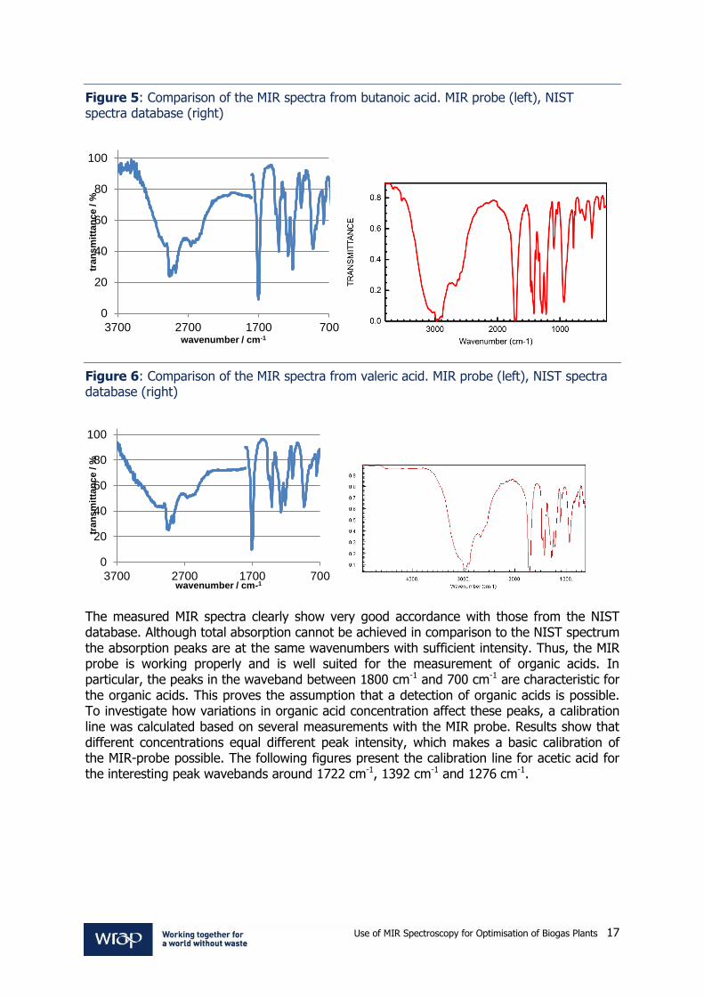
Figure 5: Comparison of the MIR spectra from butanoic acid. MIR probe (left), NIST spectra database (right)
Figure 6: Comparison of the MIR spectra from valeric acid. MIR probe (left), NIST spectra database (right)
The measured MIR spectra clearly show very good accordance with those from the NIST database. Although total absorption cannot be achieved in comparison to the NIST spectrum the absorption peaks are at the same wavenumbers with sufficient intensity. Thus, the MIR probe is working properly and is well suited for the measurement of organic acids. In particular, the peaks in the waveband between 1800 cm-1 and 700 cm-1 are characteristic for the organic acids. This proves the assumption that a detection of organic acids is possible. To investigate how variations in organic acid concentration affect these peaks, a calibration line was calculated based on several measurements with the MIR probe. Results show that different concentrations equal different peak intensity, which makes a basic calibration of the MIR-probe possible. The following figures present the calibration line for acetic acid for the interesting peak wavebands around 1722 cm-1, 1392 cm-1 and 1276 cm-1.
0
20
40
60
80
100
700170027003700
tran
sm
itta
nc
e / %
wavenumber / cm-1
0
20
40
60
80
100
700170027003700
tran
sm
itta
nc
e / %
wavenumber / cm-1
Use of MIR Spectroscopy for Optimisation of Biogas Plants 18
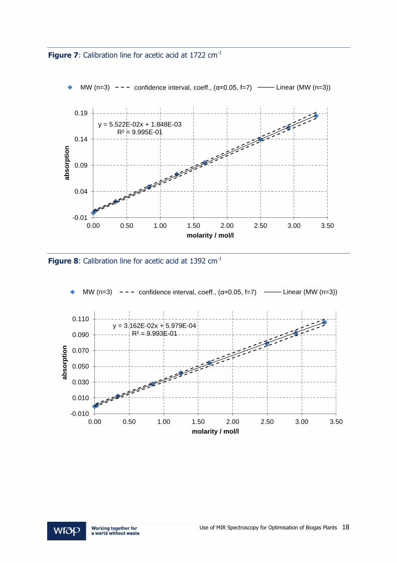
Figure 7: Calibration line for acetic acid at 1722 cm-1
Figure 8: Calibration line for acetic acid at 1392 cm-1
y = 5.522E-02x + 1.848E-03 R² = 9.995E-01
-0.01
0.04
0.09
0.14
0.19
0.00 0.50 1.00 1.50 2.00 2.50 3.00 3.50
ab
so
rpti
on
molarity / mol/l
MW (n=3) confidence interval, coeff., (α=0.05, f=7) Linear (MW (n=3))
y = 3.162E-02x + 5.979E-04 R² = 9.993E-01
-0.010
0.010
0.030
0.050
0.070
0.090
0.110
0.00 0.50 1.00 1.50 2.00 2.50 3.00 3.50
ab
so
rpti
on
molarity / mol/l
MW (n=3) confidence interval, coeff., (α=0.05, f=7) Linear (MW (n=3))

Use of MIR Spectroscopy for Optimisation of Biogas Plants 19
Figure 9: Calibration line for acetic acid at 1276 cm-1
Similar calibrations were carried out for propionic and butanoic acids as can be seen in Table 2.
Table 2: Calibration results for acetic, butanoic, propionic and iso butanoic acid with characteristic wavenumbers and corresponding correlation coefficients 1st wavenumber
(cm-1) 2nd wavenumber
(cm-1) 3rd wavenumber
(cm-1)
Acetic acid 1,722 1,392 1,276
fitted linear functions (acetic acid)
y = 5.52E-02x + 1.85E-03 3.16E-02x + 5.98E-04 y = 9.8E-03x - 1.5E-04
R² 0.99950 0.99930 0.99990
Butanoic acid 1,708 1,276 1,208
fitted linear functions
(butanoic acid)
y = 5.28E-02x + 1.89E-03 y = 2.8E-02x + 5.08E-04 4.7E-02x - 8.29E-04
R² 0.99970 0.99980 0.99930
Propionic acid 1,712 1,384 1,224
fitted linear functions (propionic acid)
y = 4.95E-02x + 9.23E-04 y = 2.741E-02x + 4.146E-04 y = 5.5E-02x - 4.28E-04
R² 0.99960 0.99950 0.99980
Iso butanoic acid 1,704 1,228
fitted linear functions (iso butanoic acid)
y = 5.08E-02x + 3.361E-05 y = 5.65E-02x - 2.8E-04
R² 0.99990 1.0000
y = 5.899E-02x - 1.510E-04 R² = 9.999E-01
-0.010
0.040
0.090
0.140
0.190
0.00 0.50 1.00 1.50 2.00 2.50 3.00 3.50
ab
so
rpti
on
molarity / mol/l
MW (n=3) confidence interval, coeff., (α=0,05, f=7) Linear (MW (n=3))

Use of MIR Spectroscopy for Optimisation of Biogas Plants 20
3.4 Verification of the MIR probe cleaning regime To investigate whether cleaning of the MIR probe is possible and the best substances for cleaning the diamond head, five different experimental setups were measured. Therefore, the MIR measurements were conducted in:
milk;
flour;
sunflower oil;
a mixture of milk, flour and sunflower oil; and
digestate from an industrial biogas plant.
After the measurement cycle, the MIR probe was cleaned in several steps with three different substances, namely deionised water, soap solution and acetone. These three substances were chosen as they represent three cleaning fluids of different strength with deionized water being the weakest and acetone the strongest substance. The following figures show the transmittance baseline before the measurement, during the measurement and after each cleaning step. The probe was exposed to the measurement medium for one measurement cycle which takes about 15 minutes. After that the cleaning started. During operation at the full-scale plant, it will be necessary to further investigate the necessary cleaning interval. Cleaning after each single measurement might not be necessary.

Use of MIR Spectroscopy for Optimisation of Biogas Plants 21
Figure 10: Cleaning of the MIR probe after the measurement of milk (3.5% fat)
For the cleaning of the sample of fat milk, it becomes obvious that all three cleaning fluids provide very good cleaning results with a transmission of more than 98%. Nevertheless, the cleaning with deionized water is not sufficient to reach the initial baseline (close to 100%). The soap solution increases cleaning performance but also fails to reach the baseline. As expected, acetone achieves the best results with transmission values that match the initial baseline or are even slightly better.
40
50
60
70
80
90
100
800900100011001200130014001500160017001800
tran
sm
itta
nc
e / %
wavenumber / cm-1
Baseline before measurement Sample: H-Milk 3,5% fat
Baseline, 1. cleaning step: A - deionised water Baseline, 2. cleaning step: B - soap solution
Baseline, 3. cleaning step: C - acetone
98.5
98.7
98.9
99.1
99.3
99.5
99.7
99.9
100.1
100.3
100.5
800900100011001200130014001500160017001800
tran
sm
issio
n / %
wave number / cm-1
Baseline before measurement Baseline, 1. cleaning step: A - deionised water
Baseline, 2. cleaning step: B - soap solution Baseline, 3. cleaning step: C - acetone

Use of MIR Spectroscopy for Optimisation of Biogas Plants 22
Figure 11: Cleaning of the MIR probe after the measurement of flour type 405
The second cleaning test using flour type 405 shows that all cleaning fluids provide very similar results close or even above the initial baseline. Transmission values higher than the initial baseline transmissions can be explained by small impurities on the optics during the baseline measurement. Considering the extremely small deviation of 0.2 to 0.4 percent, this effect can be neglected.
88
90
92
94
96
98
100
102
800900100011001200130014001500160017001800
tran
sm
itta
nc
e / %
wave number / cm-1
Baseline before measurement Sample: flour type 405
Baseline, 1. cleaning step: A - deionised water Baseline, 2. cleaning step: B - soap solution
Baseline, 3. cleaning step: C - acetone
99.4
99.6
99.8
100
100.2
100.4
100.6
100.8
101
101.2
101.4
800900100011001200130014001500160017001800
tran
sm
itta
nc
e / %
wavenumber / cm-1
Baseline before measurement Baseline, 1. cleaning step: A - deionised water
Baseline, 2. cleaning step: B - soap solution Baseline, 3. cleaning step: C - acetone

Use of MIR Spectroscopy for Optimisation of Biogas Plants 23
Figure 12: Cleaning of the MIR probe after the measurement of sunflower oil
The cleaning of the probe from oily substances is the most difficult as can be seen in the results from Figure 11. A cleaning with deionized water fails to deliver an acceptable transmission so that a cleaning with acetone was absolutely necessary in this case.
30
40
50
60
70
80
90
100
110
800900100011001200130014001500160017001800
tran
sm
itta
nc
e / %
wavenumber / cm-1
Baseline before measurement Sample: sunflower oil
Baseline, 1. cleaning step: A - deionised water Baseline, 2. cleaning step: C - acetone
99
99.2
99.4
99.6
99.8
100
100.2
100.4
800900100011001200130014001500160017001800
tran
sm
itta
nc
e / %
wavenumber / cm-1
Baseline before measurement Baseline, 2. cleaning step: C - acetone

Use of MIR Spectroscopy for Optimisation of Biogas Plants 24
Figure 13: Cleaning of the MIR probe after the measurement of a mixture of milk, flour and sunflower oil
The mixture of milk, flour and oil is also difficult to clean. Deionized water as well as soap solution are not able to achieve transmission values close to the baseline. Acetone is the only cleaning fluid, which guarantees the regeneration of the baseline.
40
50
60
70
80
90
100
800900100011001200130014001500160017001800
tran
sm
itta
nc
e / %
wavenumber / cm-1
Baseline before measurement Sample: mixture of milk, flour and oil
Baseline, 1. cleaning step: A - deionised water Baseline, 2. cleaning step: B - soap solution
Baseline, 3. cleaning step: B - soap solution Baseline, 4. cleaning step: aceton
97
97.5
98
98.5
99
99.5
100
100.5
800900100011001200130014001500160017001800
tran
sm
itta
nc
e / %
wavenumber / cm-1
Baseline before measurement Baseline, 2. cleaning step: B - soap solution
Baseline, 3. cleaning step: B - soap solution Baseline, 4. cleaning step: aceton

Use of MIR Spectroscopy for Optimisation of Biogas Plants 25
Figure 14: Cleaning of the MIR probe after the measurement of digestate from an industrial biogas plant
The cleaning results after a measurement of digestate show that all three cleaning fluids can be used to regenerate the baseline. The higher transmission values after cleaning in comparison to the baseline indicate that the small impurities were on the optics before the initial measurement.
40
50
60
70
80
90
100
800900100011001200130014001500160017001800
tran
sm
itta
nc
e / %
wavenumber / cm-1
Baseline before measurement Sample: Industrial biogas plant (not filtered)
Baseline, 1. cleaning step: A - deionised water Baseline, 2. cleaning: B - soap solution
Baseline, 3. cleaning step: C - acetone
99.6
99.8
100
100.2
100.4
100.6
100.8
101
101.2
800900100011001200130014001500160017001800
tran
sm
itta
nc
e / %
wavenumber / cm-1
Baseline before measurement Baseline, 1. cleaning step: A - deionised water
Baseline, 2. cleaning: B - soap solution Baseline, 3. cleaning step: C - acetone
Use of MIR Spectroscopy for Optimisation of Biogas Plants 26
These results clearly show that a cleaning of the MIR probe is in most cases possible with two cleaning steps, one with deionised water and the second with a soap solution. Cleaning with acetone brought additional improvement of the baseline, but this was only absolutely necessary in the case of sunflower oil, which could not be entirely removed with the first cleaning steps. In the other cases the improvement in transmittance was marginal. Thus, cleaning with acetone might be necessary if greasy substrates are used for anaerobic digestion, such as glycerol. All in all a complete cleaning of the MIR probe to re-establish the original baseline is possible. 3.4.1 References McIntyre, A.C., Bilyk, M.L., Nordon, A., Colquhoun, G. and Littlejohn, D., 2011. Detection of counterfeit Scotch
whisky samples using mid-infrared spectrometry with an attenuated total reflectance probe incorporating
polycrystalline silver halide fibres. Analytica Chimica Acta, 690 (2), 228–233.
Spanjers, H., Bouvier, J., Steenweg, P., Bisschops, I., van Gils, W. and Versprille, B., 2006. Implementation of in-
line infrared monitor in full-scale anaerobic digestion process. Water Science and Technology, 53 (4-5), 55–61.
Steyer, P., Bouvier, J.C., Conte, T., Gras, P., Harmand, J. and Delgenes, J.P., 2002. On-line measurements of
COD, TOC, VFA, total and partial alkalinity in anaerobic digestion processes using infra-red spectrometry. Water
Science and Technology, 45 (10), 133–138.
Wolf, C., Gaida, D., Stuhlsatz, A., Ludwig, T., McLoone, S. and Bongards, M., 2011. Predicting organic acid
concentration from UV/vis spectrometry measurements - A comparison of machine learning techniques.
Transactions of the Institute of Measurement and Control.

Use of MIR Spectroscopy for Optimisation of Biogas Plants 27
4.0 Legislation 4.1 Identification of the relevant regulations and legislation which will apply to the
development and/or installation of the technology, identification and mitigation of risks relating to these
The demonstration site to be used in the project is the agriAD facility at Drumnahare, near
Banbridge, County Down, Northern Ireland. Compared with England and Wales, different
regulations and legislation are applicable to the operation of an AD plant in Northern
Ireland.
Waste Management License - The demonstration site is based on a farm holding
owned and operated by the directors of agriAD. The feedstock requirement for the plant
will be met from internal farm lands, and as such does not require a waste management
license.
The project will not result in any changes to feedstock requirement that cannot be met
by internal farm lands – therefore no change in the waste managing license status will be
effected.
Standard permits for AD - The NIEA (Northern Ireland Environment Agency) have
published a set of rules that must be complied with during the commissioning and
operation of an on-farm anaerobic digester.
These rules require the license holder (in this case agriAD) to provide information to the
NIEA with respect to the biogas quality and quantity during the commissioning period and
the environmental impact of the commissioning process.
During steady operation, biogas hydrogen sulphide content and gas pressure must be
constantly monitored and records made available to NIEA on request. Records of CHP
(Combined Heat & Power) plant failure and corrective action and the use of emergency flare
must be reported to the NIEA. The plant owner must also carry out regular inspection and
servicing of the plant equipment.
The technology demonstration to be undertaken as part of this project will have no effect on
the compliance with these requirements.
Pollution Prevention & Control - The demonstration site at Drumnahare will be
subject to The Pollution Prevention and Control Regulations (Northern Ireland) 2003.
These regulations require the plant to include measures such as a gas leak detection
system and emergency flare system to prevent uncontrolled releases of biogas to the
environment.
The project will not affect the compliance of the demonstration site with these
regulations.

Use of MIR Spectroscopy for Optimisation of Biogas Plants 28
Animal by-product Regulations - The Animal By-Product Regulations (Northern
Ireland) 2003 allow the treatment in biogas plants of low-risk (category 3) Animal By-
Products (ABPs) and catering waste containing meat or which comes from a meat
handling premises. High-risk (category 2) ABPs cannot be used as feedstock, except
where they have first been rendered to the 133°C/3 bar/20 minute EU pressure-
rendering standard.
Manure and digestive tract content are classified as a category 2 ABP, but they can be
used without pre-processing except where it is used as feedstock in combination with
other ABPs.
The demonstration site is an on-farm anaerobic digestion plant which will use only grass
silage and dairy cow slurry throughout the duration of this project. As such, the ABP
Regulations are not applicable to this project.
Duty of Care - In Northern Ireland, The Controlled Waste (Duty of Care) Regulations (Northern Ireland) 2002 apply. This law says that all reasonable steps must be taken to ensure that waste is produced, stored, transported and disposed of without harming the environment. In the context of an anaerobic digestion facility, this law has an effect on the size of digestate storage facilities and digestate spreading regime. As the project may potentially lead to the feeding rate to the plant being increased, a greater volume of digestate may be created, giving rises to the risk that insufficient digestate storage space is available. This is unlikely to cause problems as the slurry holding tanks in the existing farm have sufficient capacity to serve the cattle population and there will be minimal overall change in the volume of liquid requiring storage. Nevertheless, this risk will be monitored and appropriate action taken if necessary.
Health and Safety - As part of the permitting system, agriAD has carried out a full risk assessment of the site and appropriate control measures will be employed where needed. For example, the mixing basement, where the project equipment will be located, is considered a confined space. To prevent oxygen depletion occurring in this area, an air exchange system will be used. This system has a throughput of 1,000 m3/h and is integrated into the plant safety system. The project activities will have no impact on the existing site risk assessment. In order to obtain data on the composition of the digestate, some analyses must be carried out immediately after sampling. These analyses will be carried out using standard methods. Risk assessments for each method will be carried out and full training will be provided to the operators carrying out the analysis.

Use of MIR Spectroscopy for Optimisation of Biogas Plants 29
Planning Permission - agriAD has obtained full planning permission for a 500 kW AD plant at Drumnahare. The plant is currently in construction and will be operational in early 2013; in time for use in the demonstration phase of the project. The project will have no impact on the conditions of the planning permission.
Digestate Quality - If increased monitoring does allow increased feeding, this will decrease retention time in the digester. Current retention time is approximately 50 days – a 10% increase in the feeding rate will lead to the retention time decreasing to around 45 days. This reduction in retention time may have an effect on the digester’s ability to produce digestate which is compliant with the relevant quality standards (i.e. PAS 110). The current position of the of NIEA is that when agricultural manure and slurry is destined for a treatment process (including biogas production) it is waste and will be subject to regulatory control. This is a requirement of the revised Waste Framework Directive (2008/98/EC, Article 2, 2(b)).
In order to not be regarded as waste, anaerobic digestate will have to meet the requirements of PAS110. Slurry is not, however, seen as a waste when it is used directly as a fertiliser on land. The NIEA recognises that the digestate product from manure and slurry only has improved fertilising properties and will have less of an environmental risk than undigested manure and slurry. Therefore, the NIEA will not regulate the AD digestate as waste if it the only feedstock is manure or slurry or if manure or slurry is mixed with crops grown specifically as a feedstock for AD, and the digestate is spread on agricultural land as a fertiliser. The digestate produced by the agriAD digester used for the demonstration will be used as a fertiliser within the existing farm holding. As such, any impact the technology demonstration may have on the digestate quality will have no regulatory implications.
Excise Duty/End of waste criteria for biomethane – Not applicable. The biogas produced by the AD facility will be burnt in on-site CHP units.

Use of MIR Spectroscopy for Optimisation of Biogas Plants 30
5.0 Detailed technical appraisal of technology 5.1 Theory/process behind the technology Middle Infrared spectroscopy The middle-infrared wavelength range goes from 2.5µm to 50µm and has advantages over other ranges as substances tend to have clear and characteristic reflection spectra that are well suited for indirect measurement purposes when using powerful machine learning techniques. Nevertheless, measuring in the MIR-wavelength range has proven to be difficult due to a lack of adequate fibre optics available on the market. The company Fibre Photonics, which produces fibre optics and immersion probes for UV/vis, NIR and MIR spectroscopy, has overcome these problems by developing new fibre-optics (PIR – Polycrystalline IR-Fibres) with reduced damping and optimized bending of the fibre. Thus, these fibre-optics are perfectly suited for measurements in the MIR wavelength range up to 18µm.
Figure 15: Example of a transmission spectrum for Formaldehyde over the MIR-range.
Newly developed MIR reflection probes made from stainless steel allow for a robust online-measurement of AD process parameters. Figure 16 shows the basic measurement principle, where MIR spectra are collected and then analysed to predict VFA or FOS concentrations.
Figure 16: Principle of MIR online-measurement system

Use of MIR Spectroscopy for Optimisation of Biogas Plants 31
The theory behind this kind of online measurement is that each substance has a characteristic absorption pattern in the MIR wavelength band. With increasing concentration of the substances the absorption also increases, which allows the VFAs to become detectable in the measured spectra. If these changes in the spectra over time are properly analysed, the actual concentration of a desired substance can be calculated at any time. This kind of online-measurement is called indirect measurement because the concentration of a substance is not measured directly with a specially adapted chemical method, but instead calculated based on measured absorption spectra. The MIR probe used in this case is a diamond tipped ATR probe. This probe is extremely robust and can withstand the strongest abrasive forces during online operation. The probe can be delivered with up to 3m of fibre optics cable length and is available in lengths from 100 to 500cm. Furthermore, different diameters are available from 12mm to 50mm. The used fibre-optics for MIR probes are PIR Fibres for Mid IR range 550 ‐3300cm-1 (3 ‐18 μm)
and CIR (Chalcogenide glass IR) Fibres Near IR / Mid IR range 1650 ‐6650cm-1 (1.5 ‐ 6.0
μm), which are produced by Fibre Photonics. The required spectrometer for analysing purposes, which covers the NIR and MIR wavelength range, is manufactured by ABB. The probe is available in three different materials Hastelloy (C22, C276), Stainless Steel (316L) and Titanium. The MIR probe is manufactured by Fibre Photonics and its German partner company A.R.T. Photonics. The installation fitting for the probe is made of stainless steel and possesses a fully automated control system to pull the probe back into a cleaning chamber for multiple cleaning cycles with different chemical fluids. The assembling of probe housing, fibre-optics and spectrometer is done by Fibre Photonics. The installation of the probe will be performed by Fibre Photonics in close collaboration with the AD plant operator/owner and the participating research organisations.
Figure 17: Diamond-tipped ATR probe for MIR
Two things about the MIR measurement system used in this project are different from conventional systems:
the fully automated cleaning and recalibration systems; and
data analysis with powerful machine learning methods as described in Section 3.
The advantages of such a system are a reliable prevention of clogging and fouling of the probe, which is a common problem associated with spectroscopic online-measurements, and a fast, high quality spectral analysis,

Use of MIR Spectroscopy for Optimisation of Biogas Plants 32
Figure 18: MIR-probe suffering from severe clogging and fouling before and after cleaning
The automatic cleaning system uses up to three different chemical liquids, which are specially adapted to the matrix of the measurement medium. These are consecutively, automatically pumped in a cleaning chamber of the installation fitting. After each cleaning step the absorption spectrum in deionized water is measured and compared to previously taken reference spectra. If cleaning is sufficient, the process will be stopped, if not it is continued. Furthermore, the degree of fouling and clogging can be estimated by the measurement of these reference samples at any time during operation, so that cleaning is only performed if necessary.
Figure 19: Fully automated cleaning of the MIR probe
The software to control the cleaning of the probe as well as the algorithms for data analysis are integrated in a process control unit that comes from the company Knick Elektronische Messgeräte GmbH & Co. KG and was specially adapted by Fibre Photonics. Thus, the complete online-measurement system consists of three basic components: the MIR probe, the installation fitting with cleaning chamber and the process control unit.

Use of MIR Spectroscopy for Optimisation of Biogas Plants 33
Figure 19: Complete MIR online-measurement system for AD processes
Description of in situ installation The MIR probe will be installed in a bypass line where a representative sample of digestate can be analysed. Due to the guidelines for Explosion Protection and Prevention for AD plants an installation inside the main digester is not possible or would require substantial changes in the probe design, resulting in much higher manufacturing prices. The ideal situation is a line in which digestate pumped into the main digester and from the main digester to the secondary digester, allowing a measurement from the input material and the fermentation sludge to be achieved with only one probe. For single tank digesters, a sample loop is easily constructed to allow monitoring of reactor VFA concentrations. The measurement data will be stored in a database at the AD plant. The connection between sensor and database will be realised using the Open Process Control (OPC) interface for data transmission. To recognise which pump stream is currently measured, modifications have to be made to the process control system at the AD plant. These will be programmed into the local PLC. 5.2 Operational parameters The operational parameters for the MIR measurement system are 240 V to power the process control and cleaning unit as well as the spectrometer. Furthermore, it is important to protect the fibre cable against strong bending and violent pressure. To guarantee a sufficient cleaning and drying of the probe, compressed air needs to be available at the plant, which is a common (relatively inexpensive) piece of equipment on agricultural holdings. The installation of the complete MIR measurement system requires a space of 1 m². 5.3 Comparison with ‘business as usual’ The state-of-the-art way to measure and monitor organic acid concentration on agricultural biogas plants unfortunately is still to perform laboratory analysis of the fermenting sludge and substrate feed on a regular basis. This thorough analysis allows efficient process operating conditions to be determined and indicates whether a process is stable or in

Use of MIR Spectroscopy for Optimisation of Biogas Plants 34
danger. However, performing the analysis and interpreting the results requires detailed knowledge about the fermentation process, and access to such expertise is generally only cost effective for the largest biogas production facilities. Furthermore, laboratory analyses are difficult, expensive and time-consuming, which makes effective process monitoring and control impractical. Based on the current situation in the field of online measurement systems for biogas plants, the need for new developments in sensor technology and engineering solutions in this area is huge. Existing technologies for online measurements of organic acid concentrations in biogas plants, such as gas-phase chromatographs or automatic titrators, are only used by a small group of skilled AD plant operators, as they are expensive and high-maintenance products. 5.4 Range The range of applicability for the MIR measurement system can be best described by analysing the biogas market in Germany, which is much more developed than in the U.K. Currently there are approximately 7,100 biogas plants in Germany according to the German Biogas Association (www.biogas.org). Nevertheless, the recent biogas measurement program in Germany (FNR e.V. 2009) showed instrumentation at full-scale biogas plants to be still in its infancy. Currently 70% of biogas plants in Germany possess measurement systems for biogas production and 60% have systems for measuring biogas composition. Liquid and solid substrate feed are measured at 50% and 80% of the plants, respectively. In contrast, the more sophisticated measurement systems, such as online pH, redox potential or even VFA analysis are available at less than 5% of all plants. This leaves lots of potential for the application of innovative online measurements to improve plant performance and presents a huge market for manufacturers of online measurement systems. Furthermore, there is substantial research activity in this area aiming to provide new robust and feasible measurement systems. Considering the fact that roughly 50% of all biogas plants have more than 300 kWe of capacity and are thus bigger plants that can afford the most from detailed process monitoring technology, the market for the MIR measurement system consists of 3,500 biogas plants in Germany alone. Looking at the European market the potential for such a system would be even higher. The MIR measurement system is considered to be too expensive (approximately £30k – £40k) for small biogas plants as the return on investment is not achieved within an acceptable timeframe. 5.5 Life cycle of technology The life span of the MIR probe can only be estimated based on previous experience and is expected to be 20 years. For the process control and cleaning system, the life span is approximately 15 years. Of course, regular maintenance of the complete system is absolutely necessary to guarantee the functionality of the system as long as possible.

Use of MIR Spectroscopy for Optimisation of Biogas Plants 35
5.6 Risk Analysis The following risks to the successful completion of the project have been identified:
Table 3: Risk Analysis
Risk Mitigation
Drumnahare facility construction delayed due to inclement weather etc.
The project can be paused without costs to the project being incurred. If the delay is to be excessive, an alternative demonstration site can be sought; the non-commercial digester at AFBI Hillsborough and other Envitec digesters are candidate sites.
Failure of MIR Probe The laboratory probe used in the experiments carried out in the feasibility stage will be held in reserve and can be employed at the demonstration site until Fibre Photonics can manufacture a replacement
Failure of analytical equipment Through the QUESTOR Centre, the project will have access to additional analytical equipment in the School of Chemistry and Chemical Engineering and elsewhere in the university. If required, external laboratories can be used.
5.7 References FNR e.V., 2009. Biogas-Messprogramm II - 61 Biogasanlagen im Vergleich: (Biogas Measurement Program II - A comparison of 61 German biogas plants). 1st ed. Gülzow: Fachagentur Nachwachsende Rohstoffe (Agency for Renewable Resources).

Use of MIR Spectroscopy for Optimisation of Biogas Plants 36
6.0 Economic/Cost Benefit Analysis 6.1 Appraisal of cost to industry/facilities including capex and opex and other associated
financial benefits The MIR probe is in early prototype stage. Using the outputs from this project, it is hoped that a complete online-measurement system based on the MIR probe will be ready for launch into the market in the last quarter of 2013. Drawing on experience from similar applications in other industrial sectors, it is estimated that the MIR online-measurement system will be made available at a market price of £30,000. It is estimated that installation of the probe and integration into the existing plant control system will be possible for approximately £10,000, giving a total Capital Expenditure of £40,000. Operating costs of the system are minimal. The probe uses optical sensing only and as such contains no sensing fluids. The probe is diamond tipped and therefore inert and very robust; it will not require frequent replacement in comparison to online pH or redox potential meters. A system life of 10 years minimum is to be expected. The only operational expenses are in servicing and the provision of cleaning fluids. Estimates are that an annual service and a year’s supply of cleaning fluids will cost less than £1,500. Using a ten year serviceable life, this gives a total investment of £55,000. Financial benefits of the system will be realised through increased operational efficiency allowing the generation of additional electricity with associated increased income and realisation of increased biogas yields allowing savings in feedstock costs. 6.2 Comparative Cost Benefit Analysis versus ‘business as usual’ The data contained in Table 4 and Table 5 is adapted from a financial model which was prepared by KPMG for agriAD’s business plan. It is based on a 499 kWe biogas plant with a combined heat and power system. This is likely to be typical of the size of plants built in Northern Ireland as it is the largest size of plant eligible for 4 ROCs support. The model considers:
cost of silage as feedstock;
revenue from electricity sales;
revenue from capacity payments;
revenue from Renewable Obligation Certificates (ROCs); and
revenue from Levy Exemptions Certificates (LECs).
The following assumptions are used:
silage costs are £25 per tonne delivered to the feeding hopper of the biogas plant;
7% of the electrical energy generated by the plant is consumed by the plant operations;
revenue from electricity sales are paid on the net amount of electrical energy exported to the grid. A wholesale price of £52.53/MWh is used;
revenue from capacity payments is paid on the net amount of electrical energy exported to the grid. A price of £8.05/MWh is used;
revenue from ROCs is paid on the total amount of electrical energy exported to the grid. Each MWh of electricity earns 4 ROCs and each ROC has a price of £47.28;
revenue from LECs is paid on the total amount of electrical energy exported to the grid. A price of £5.10/MWh is paid;

Use of MIR Spectroscopy for Optimisation of Biogas Plants 37
the Power Purchase Agreement (PPA) dictates the fraction of generated electricity eligible for each form of payment (as detailed in Table 4 and Table 5);
the values of the electrical wholesale price, capacity payments, ROCs and LECs are taken from the KMPG report; and
An annual basis is used.
Scenario A – 10% increase in biogas production due to increased feedstock loading. The figures shown in Table 4 explain the effect on the plant finances of a 10% increase in the biogas production of the AD plant due to increased organic loading of the digester through additional feeding of silage only (no additional slurry). This will allow additional revenue to be obtained as the additional biogas will lead to more operational hours of the CHP system and more electricity being generated.

Use of MIR Spectroscopy for Optimisation of Biogas Plants 38
Table 4: Cost benefit of project – Scenario A: 10% increase in biogas production due to increased feedstock loading Unit Business as
Usual Target Project
benefit
Engine size kW 499 499
Operational Efficiency 89.60% 98.56%
Operational Hours h/year 7,849 8,634
Electrical Energy Generated kWh/year 3,916,631 4,308,294
Biogas -> Electricity Conversion kWh(e)/m3 2 2
Biogas Volume m3/year 1958316 2154147
Feedstock
Biogas yield (slurry) m3/tonne 62 62
Slurry requirement tonnes/year 3250 3250
Biogas yield (silage) m3/tonne 150 150
Silage requirement tonnes/year 11712 13018
Silage price £/tonne 25 25
Silage cost £/year - £ 292,803 -£ 325,441 -£ 32,639
Electricity Sales
MWh exported MWh/year 3642 4007
Electricity Price £/MWh 52.53 52.53
PPA offer 92% 92%
Electricity Sales Revenue £/year £ 176,032 £ 193,635 £ 17,603
Capacity Payments
MWh exported 3642 4007
Capacity Payment Price £/MWh 8.05 8.05
PPA offer 90% 90%
Capacity Payments Revenue £/year £ 26,390 £ 29,029 £ 2,639
ROCs
Electricity exported MWh/year 3917 4308
No of ROCs 4 4
ROCs cost £/MWh 47.28 47.28
PPA offer 90% 90%
ROCs revenue £/year £ 666,642 £ 733,306 £ 66,664
Levy Exemption Certificates
Electricity exported MWh/year 3917 4308
LEC price £/MWh 5.1 5.1
PPA offer 70% 70%
LECs Revenue £/year £ 13,982 £ 15,381 £ 1,398
Totals £590,243 £645,909 £ 55,666
The figures in Table 4 show that if the technology is able to deliver a 10% increase in operational efficiency, £55,666 of additional income will be obtained. This is an increase of 9.4% in annual income. Based on the total investment for installation and integration of the MIR system of £55,000, this indicates a payback for the system of just less than 12 months.
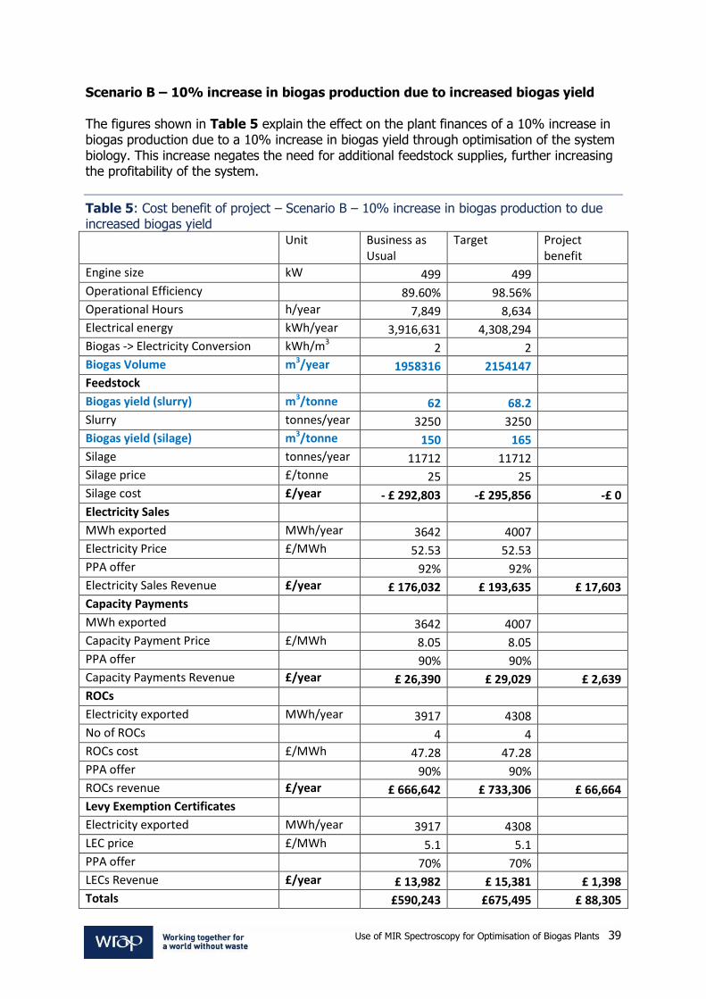
Use of MIR Spectroscopy for Optimisation of Biogas Plants 39
Scenario B – 10% increase in biogas production due to increased biogas yield The figures shown in Table 5 explain the effect on the plant finances of a 10% increase in biogas production due to a 10% increase in biogas yield through optimisation of the system biology. This increase negates the need for additional feedstock supplies, further increasing the profitability of the system.
Table 5: Cost benefit of project – Scenario B – 10% increase in biogas production to due increased biogas yield Unit Business as
Usual Target Project
benefit
Engine size kW 499 499
Operational Efficiency 89.60% 98.56%
Operational Hours h/year 7,849 8,634
Electrical energy kWh/year 3,916,631 4,308,294
Biogas -> Electricity Conversion kWh/m3 2 2
Biogas Volume m3/year 1958316 2154147
Feedstock
Biogas yield (slurry) m3/tonne 62 68.2
Slurry tonnes/year 3250 3250
Biogas yield (silage) m3/tonne 150 165
Silage tonnes/year 11712 11712
Silage price £/tonne 25 25
Silage cost £/year - £ 292,803 -£ 295,856 -£ 0
Electricity Sales
MWh exported MWh/year 3642 4007
Electricity Price £/MWh 52.53 52.53
PPA offer 92% 92%
Electricity Sales Revenue £/year £ 176,032 £ 193,635 £ 17,603
Capacity Payments
MWh exported 3642 4007
Capacity Payment Price £/MWh 8.05 8.05
PPA offer 90% 90%
Capacity Payments Revenue £/year £ 26,390 £ 29,029 £ 2,639
ROCs
Electricity exported MWh/year 3917 4308
No of ROCs 4 4
ROCs cost £/MWh 47.28 47.28
PPA offer 90% 90%
ROCs revenue £/year £ 666,642 £ 733,306 £ 66,664
Levy Exemption Certificates
Electricity exported MWh/year 3917 4308
LEC price £/MWh 5.1 5.1
PPA offer 70% 70%
LECs Revenue £/year £ 13,982 £ 15,381 £ 1,398
Totals £590,243 £675,495 £ 88,305

Use of MIR Spectroscopy for Optimisation of Biogas Plants 40
The figures in Table 5 show that, if these improvements are realised, the increased biogas production with no increased feedstocks requirements mean an additional annual income of £88,305 will be obtained. This is an increase of 15.0% on annual project income. In these circumstances, the technology is even more attractive, with a payback period of approximately 8 months. These projections are based on an existing AD facility. If both increased loading and increased biogas yield were realised simultaneously (i.e. a 20% increase in biogas production), the facility in question could not process the additional biogas without the installation of additional engine capacity. As such, some existing plants would not be able to achieve the full benefits of this technology. However, for future plants, the knowledge of the benefits will lead to the construction of smaller plants which operate at higher organic loading rates and provide significant capital costs savings. Also, better, real-time monitoring of VFA concentration in biogas plants will prevent biological failure caused by excessive VFA build up. From the experiences of Envitec AG, biological failure results in the loss of the equivalent of 45 days biogas whilst the digester tank is emptied, refilled and re-undergoes the commissioning process. Calculations carried out by consultants KPMG on behalf of agriAD estimated this cost to be £0.16 per kWh lost, even when savings in the utilisation of feedstock is taken into account. For a 499 kW plant operating at an operational efficiency of 89.6%, a downtime of 45 days results in the loss of 482,872 kWh at a cost to the business of £77,260. This loss of revenue can be prevented through better monitoring providing by this technology.
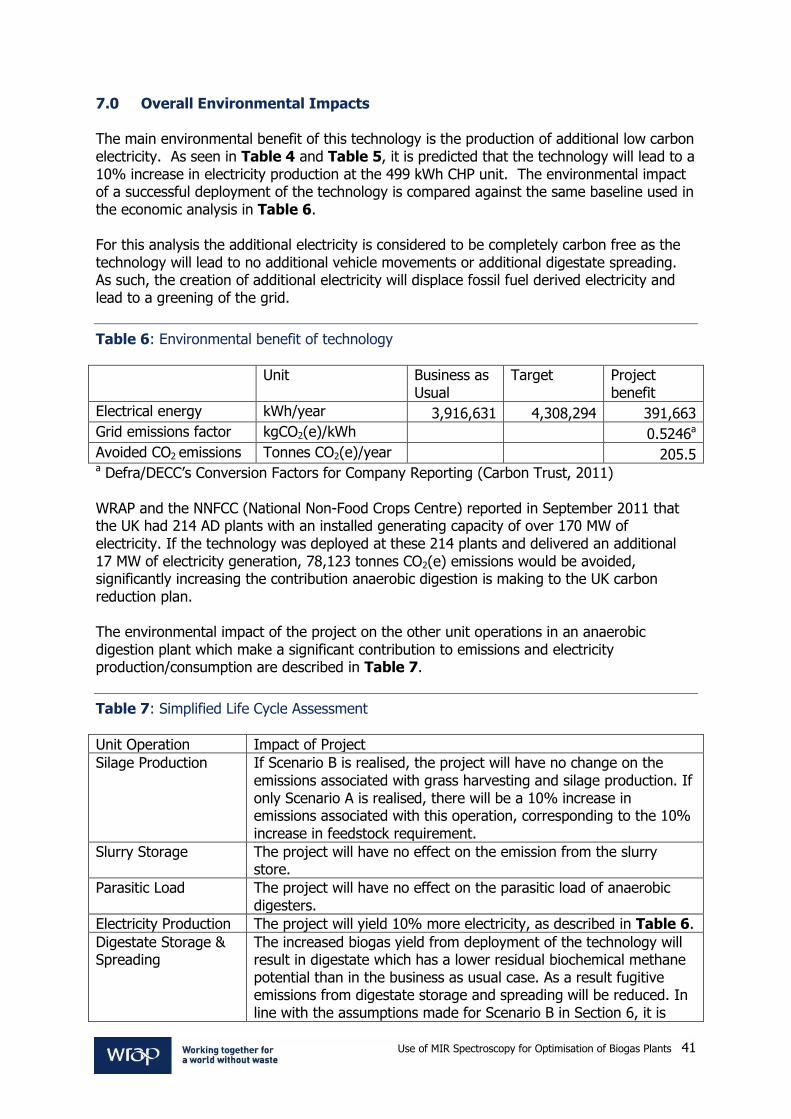
Use of MIR Spectroscopy for Optimisation of Biogas Plants 41
7.0 Overall Environmental Impacts The main environmental benefit of this technology is the production of additional low carbon electricity. As seen in Table 4 and Table 5, it is predicted that the technology will lead to a 10% increase in electricity production at the 499 kWh CHP unit. The environmental impact of a successful deployment of the technology is compared against the same baseline used in the economic analysis in Table 6. For this analysis the additional electricity is considered to be completely carbon free as the technology will lead to no additional vehicle movements or additional digestate spreading. As such, the creation of additional electricity will displace fossil fuel derived electricity and lead to a greening of the grid.
Table 6: Environmental benefit of technology
Unit Business as Usual
Target Project benefit
Electrical energy kWh/year 3,916,631 4,308,294 391,663
Grid emissions factor kgCO2(e)/kWh 0.5246a
Avoided CO2 emissions Tonnes CO2(e)/year 205.5 a Defra/DECC’s Conversion Factors for Company Reporting (Carbon Trust, 2011) WRAP and the NNFCC (National Non-Food Crops Centre) reported in September 2011 that the UK had 214 AD plants with an installed generating capacity of over 170 MW of electricity. If the technology was deployed at these 214 plants and delivered an additional 17 MW of electricity generation, 78,123 tonnes CO2(e) emissions would be avoided, significantly increasing the contribution anaerobic digestion is making to the UK carbon reduction plan. The environmental impact of the project on the other unit operations in an anaerobic digestion plant which make a significant contribution to emissions and electricity production/consumption are described in Table 7.
Table 7: Simplified Life Cycle Assessment
Unit Operation Impact of Project
Silage Production If Scenario B is realised, the project will have no change on the emissions associated with grass harvesting and silage production. If only Scenario A is realised, there will be a 10% increase in emissions associated with this operation, corresponding to the 10% increase in feedstock requirement.
Slurry Storage The project will have no effect on the emission from the slurry store.
Parasitic Load The project will have no effect on the parasitic load of anaerobic digesters.
Electricity Production The project will yield 10% more electricity, as described in Table 6.
Digestate Storage & Spreading
The increased biogas yield from deployment of the technology will result in digestate which has a lower residual biochemical methane potential than in the business as usual case. As a result fugitive emissions from digestate storage and spreading will be reduced. In line with the assumptions made for Scenario B in Section 6, it is
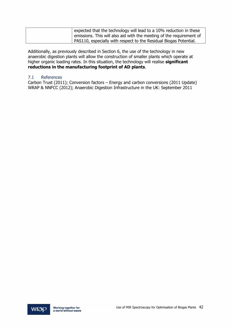
Use of MIR Spectroscopy for Optimisation of Biogas Plants 42
expected that the technology will lead to a 10% reduction in these emissions. This will also aid with the meeting of the requirement of PAS110, especially with respect to the Residual Biogas Potential.
Additionally, as previously described in Section 6, the use of the technology in new anaerobic digestion plants will allow the construction of smaller plants which operate at higher organic loading rates. In this situation, the technology will realise significant reductions in the manufacturing footprint of AD plants. 7.1 References Carbon Trust (2011); Conversion factors – Energy and carbon conversions (2011 Update) WRAP & NNFCC (2012); Anaerobic Digestion Infrastructure in the UK: September 2011
Use of MIR Spectroscopy for Optimisation of Biogas Plants 43
PHASE 2 DEMONSTRATION 7.2 Methodology for demonstration If the project is successful in proceeding to Stage 2 of the DIAD programme, this project shall begin in September 2012. The project shall be delivered as a series of 5 Work Packages (WPs). These work packages will take place alongside the construction of the Drumnahare AD facility which is being undertaken by two of the project partners (agriAD and Envitec Biogas UK). WP1 - Project Management This work package will ensure the smooth running of the project according to the work plan and that all targets and deliverables are met in a timely fashion. Tasks:
establish a consortium agreement between partners;
ensure good communication between the project partners through holding of regular consortium meetings and conference calls;
hold regular communication with WRAP to ensure project meets the goals of the DIAD programme as well as those of the project partners;
produce suitable reports to disseminate the project outcomes and benefits; and
manage all financial aspects of the project.
WP2 - Design specification, equipment procurement and installation agriAD, in conjunction with Envitec, will shortly begin construction of the Drumnahare AD facility which will be used for the demonstration aspect of the project. The site scoping exercise carried out as part of the feasibility study identified that the Kreis-dissolver is the ideal location in an Envitec plant to deploy the probe, but that some modifications to their current offering is needed and that some additional equipment is required. The project partners will work together during the design clarification stage to ensure these modifications are made to the final design of the Drumnahare AD facility. This work package will also include the procurement and installation of the probe and associated equipment and the analytical equipment required to carry out the project. Tasks:
specification of modification to Envitec offer to facility project;
procurement and installation of MIR probe, spectrophotometer, datalogger, connections etc.; and
procurement of analytical equipment and training of operators in analytical techniques.
WP3 - Cleaning regime optimisation and spectral characteristics The laboratory work carried out with the probe verified its ability to use the spectral characteristics of digestate samples to measure the VFA concentration. It also demonstrated that the probe could be successfully cleaned and recalibrated in situ. However, this work also showed that there is variation in the best wavelengths for accurate VFA concentration determination depending on the nature of the sample. Additionally, the
Use of MIR Spectroscopy for Optimisation of Biogas Plants 44
nature of the sample also dictates the best choice of cleaning fluids and the frequency of cleaning.
This work package will take place during early operation of the Drumnahare AD plant and will define the best spectral regimes with which to measure VFA concentration. The best regime for the digestate will also be determined. Tasks
determination of spectral characteristics of agriAD digestate; and
optimisation of cleaning regime (choice of cleaning fluid, frequency).
WP4 – Testing This work package is in two phases. Firstly the probe and other monitoring equipment will be used to establish a baseline of ‘normal’ plant performance.
In the second phase, following a review of the baseline data, the measurements from the MIR probe will be used to make manual adjustments to the feed regime, increasing the organic loading to the plant. The same parameters will be monitored to ascertain the effect on the process this change has. Tasks
analysis and logging of all available data - probe: VFA concentrations; - digestate analysis: pH, redox potential, FOS/TAC ratio, speciated VFAs, ammoniacal
nitrogen, volatile and total solids; - plant: digester temperature, biogas production volume, biogas quality, electricity
production, feeding rate etc.;
if data indicates it is possible, manual changes of feed regime; and
monitoring of changes in process (biogas production volume, biogas quality, electricity production, digestate quality).
WP5 – Commercialisation planning The MIR probe, analyser system and other associated equipment, which will be used in this project is not yet ready to be launched as a commercial product. For example, the analyser to be used in the project is more complex (and therefore more expensive) – it is capable of measurement in the full range of the IR spectrum, whilst it likely to be shorter ranges of wavelengths that are required for VFA measurement. Part of the work to be undertaken in this WP will define the spectral range required. Additionally, development of the MIR measurement system will require input from organisations that are not part of the project consortium. This WP will also identify potential commercialisation partners and work with them to identify a method of funding of the commercial product. Commercialisation is further discussed in Section 11. Tasks
define characteristics of commercial MIR spectroscopy product;
develop consortium required to deliver commercial system; and
seek funding required to achieve commercialisation.

Use of MIR Spectroscopy for Optimisation of Biogas Plants 45
The timescales of each of these work packages is illustrated in Figure 20 and discussed further in Section 10. 7.3 Include any statements confirming/evidencing the selection and securing of sites,
stakeholders, personnel and contractors The following organisations have confirmed commitment to the Phase 2 Demonstration Project:
Table 8: Project Partnership
Organisation Input to Project
Questor Centre, Queen’s University Belfast Project management, digestate analysis and expertise in the operation and optimisation of anaerobic digestion processes.
Gummersbach Environmental Computing Center, Cologne University of Applied Sciences
Probe installation, setup and calibration. Expertise in process control, simulation and optimisation of anaerobic digestion plants.
agriAD Provision of the demonstration site and feedstocks at Drumnahare. Installation of the probe and spectroscopy system. Collection of digestate samples for analysis and commercialisation of the MIR system.
Envitec Biogas UK Installation of probe and associated equipment, data acquisition and commercialisation of the MIR system.
Fibre Photonics Provision and installation of the MIR probe, expertise in spectroscopy and commercialisation of the MIR system.

Use of MIR Spectroscopy for Optimisation of Biogas Plants 46
8.0 Complete and detailed project timescale The project will take place alongside the construction of Drumnahare AD facility by agriAD and Envitec. This is illustrated in the Gantt Chart (Figure 20). The technology does not require any permitting in addition to those already secured by agriAD for the Drumnahare AD plant. For the duration of the project, all feedstock will be provided by agriAD from internal farm lands at the Drumnahare site, which is owned by fellow directors of agriAD. This commitment to provide feedstock will be contained in the Stage 2 consortium agreement. Energy purchase and grid connections have previously been secured by agriAD as part of the development of the Drumnahare project. 8.1 Project Financing If successful, the project will be part funded through WRAP, with the match funding being provided by the industrial partners in the project from their internal resources. agriAD, Envitec and Fibre Photonics have agreed to make the time their staff spend working on the project an in-kind contribution. 8.2 Operation Operation of the probe and cleaning system will be automated. Digestate samples will be collected by operators at Drumnahare plant, who will be given full training on correct sample collection, sample analysis (of those parameters requiring immediate measurement ie. pH, redox potential and FOS/TAC) and sample storage procedures by experienced staff from the QUESTOR Centre. 8.3 Monitoring and evaluation In order to qualify and quantify the usefulness of the technology, the following data will be measured and logged:
Table 9: Parameters to be monitored during demonstration
Process Parameter Method of Measurement/Location
Speciated VFAs concentration MIR Probe, digestate recycle line
Speciated VFAs concentration Digestate sample, QUESTOR laboratory GC
Ammoniacal Nitrogen Digestate sample, QUESTOR laboratory
Total and Volatile Solids Content Digestate sample, QUESTOR laboratory
FOS/TAC ratio Digestate sample, onsite analyser
pH Digestate sample, onsite analyser
Redox potential Digestate sample, onsite analyser
Digester temperature SCADA
Substrate loading SCADA
Biogas production volume SCADA
Biogas quality SCADA
Electricity production SCADA
Other information available from the plant’s SCADA system may prove useful. agriAD have agreed to make the full SCADA system available to the project and the data collection regime shall be reviewed at each consortium meeting.

Use of MIR Spectroscopy for Optimisation of Biogas Plants 47
8.4 Decommissioning The Drumnahare AD plant will continue to operate after the completion of the project. It is anticipated the probe will continue to be of use and funding sought in order to integrate the VFA measurement system into the plant control system.

Use of MIR Spectroscopy for Optimisation of Biogas Plants 48
Figure 20: Gantt Chart

Use of MIR Spectroscopy for Optimisation of Biogas Plants 49
9.0 Project milestones The project is planned within five workpackages (WPs) which will take place alongside the construction of the Drumnahare AD facility by two of the project partners (agriAD and Envitec Biogas UK). Assuming project commencement at the beginning of September 2012 indicative completion dates for each workpackage within the two-year project are shown in Table 10; milestones are listed and described in Table 11. (see also Figure 20)
Table 10: Project workpackages and estimated completion dates
Workpackage Workpackage Name Estimated Completion
Date
WP1 Project Management 31/08/14
WP2 Design specification, equipment procurement and installation
30/04/13
WP3 Cleaning regime optimisation and spectral characteristics 31/05/13
WP4 Testing 15/08/14
WP5 Commercialisation planning 31/08/14
Table 11: Project milestones and estimated dates
Milestone Milestone Description Estimated Date
Milestone 1. Decision on optimum placement of probes and sampling ports 31/10/12
Milestone 2. Commencement of plant feed/heating and supply of samples to WP2 for probe calibration
01/02/13
Milestone 3. Baseline commissioning complete; begin live data collection 01/05/13
Milestone 4. Review of data – decision point re continuation of testing regime or move to uprated feeding regime
30/09/13
Milestone 5. Technical feasibility confirmed – proceed with commercialisation
28/02/14

Use of MIR Spectroscopy for Optimisation of Biogas Plants 50
10.0 Commercialisation of technology post demonstration 10.1 Plan for approaching the market A successful trial will quantify the benefits and payback of employing a MIR based monitoring system for biogas plants, allowing higher loading rates to be employed and higher biogas production rates to be achieved. The benefits of the system will be disseminated throughout the biogas sector, both in the U.K. and across Europe, through the existing contacts of the consortium and through suitable industrial journal publications and presentations at trade shows and conferences etc. agriAD is already in receipt of funding from the Department of Agriculture and Regional Development (DARD) Biomass processing challenge fund to facilitate open operation of their biogas facility to visitors. agriAD is expected to provide increased data about plant performance to DARD and to the rest of the farm community and biogas industry in Northern Ireland. Therefore, this collaboration is an ideal opportunity for Fibre Photonics to test the probe and monitoring system and obtain data from a closely monitored plant, which will then be widely disseminated. This project will expedite the testing of the probe under real conditions and establish a relationship between the technology provider (Fibre Photonics) and two end users (agriAD and EnviTec Biogas UK). This relationship will aid the entry of the system into the market and demonstrate the benefits of improved monitoring. At this stage, this relationship is informal, but it is envisaged that a formal relationship will be entered in to following a successful demonstration of the technology. The outputs of the project will allow definition of the characteristics of a commercial MIR spectroscopy product for monitoring of biogas plants. The project partners will work in WP5 to develop a commercialisation strategy, identifying the aspects of the commercial product that can be delivered by each member of the project consortium and which aspects need input from other companies and organisations. This is described in more detail in Section 10.5 below. 10.2 Standards and regulation There is currently no relevant standard for measurement of VFA concentration in anaerobic digestate. Due to the potentially explosive atmospheres in which the commercial product will be deployed, the product will have to obtain CE marking in order to be sold with the European Economic Area (EEA). This has already been obtained for similar products which have used MIR spectroscopy in other industrial applications; the modifications required for this technology will not interfere with this and as such this does not represent a barrier to market. 10.3 Anticipated size of the market to be approached There is significant market for such a system. In the U.K., there are currently 214 AD plants (including waste water treatment works) treating a variety of feedstock types: Food Waste, Farm Wastes, Purpose Grown Crops and Wastewater Sludges. As VFA concentration is a key parameter for monitoring in all anaerobic digestion processes, this technology is applicable to all of these plants. Elsewhere in Europe, there are approximately 12,000 AD plants, the majority of which are in Germany. This number is being added to all the time. In Northern Ireland for example (where there is generous support for AD through ROCs), there are 6 operational plants, 4 of which have been commissioned in the last six months. There are also 80 plants going through the

Use of MIR Spectroscopy for Optimisation of Biogas Plants 51
planning process, of which 19 have been granted planning permission. QUESTOR has contact with 6 of the plants in planning stages. 10.4 Projections for industry uptake in year 1, 2, 5, 10 etc Fibre Photonics plan the probe and monitoring system will be ready for entry into the market in 2014. Sales will be affected by the price of the technology and government subsidies for energy produced by biogas plants, but current estimates predict sales of 10-20 systems in year 1, 40-60 systems in year 2, 150-200 in year 5 and reaching 300 sales per year by year 10. 10.5 Companies likely to deliver the technology A commercial system shall consist of the following elements:
MIR probe and fibre for signal transmission;
installation fitting with automated cleaning;
spectrophotometer for data processing; and
SCADA system for remote monitoring.
Additionally, the following services shall be required:
probe installation;
laboratory analysis; and
data analysis and probe calibration.
The companies and organisation in a position to deliver these products and services are illustrated in Figure 21.
Figure 21: Commercialisation Strategy

Use of MIR Spectroscopy for Optimisation of Biogas Plants 52
As seen in Figure 21, the majority of the roles required for the commercialisation of the technology can be filled by project partners. Project partners have existing relationships with Knick GmbH who provide the installation fittings and Bruker, ABB and Mettler who are spectrophotometer manufacturers. Discussions with these organisations and with the as yet unidentified automation company will take place as part of Work Package 5. Both Fibre Photonics and CUAS have existing links with automation companies and these companies shall be approached as part of the commercialisation task. This project arose out of a developing FP7 proposal (under Research for the Benefit of SMEs) for which preparation began in March 2011. This was not developed fully for the 2012 call deadline in December 2011, however one work package instead formed the basis of this project. Further development of the proposal concept and completion of the consortium has since taken place. The focus of the FP7 application for the November 2012 deadline will now be on data integration and modelling via a cloud computing platform for improved AD plant control. If successful under UK funding, this project team will also form part of the consortium of the expanded FP7 application. This will allow the data from MIR probe to form a core part of the data supply to the model and ‘learning software’ which will represent a further iteration in the development of smart control for next generation AD plants.

Use of MIR Spectroscopy for Optimisation of Biogas Plants 53
11.0 Key personnel QUESTOR Dr Elaine Groom is a Microbiologist who joined QUESTOR in 1996. She has extensive knowledge and practical experience of the anaerobic digestion process, including design, operation and optimisation of plants for specific feedstocks. This has been developed through work with industry including commercial trials of biogas production at the laboratory and pilot scale. She is currently leading projects on biogas production from energy crops and nutrient recovery from digestate. Simon Murray is a Chemical Engineer with four years’ experience working in research and technology transfer projects. He is currently engaged in technology transfer projects involving innovation in anaerobic digestion and energy recovery from ‘waste’ tyres. Dr Julie-Anne Hanna is a Chemical Engineer who joined the QUESTOR Centre team in 2003, becoming the manager of the Applied Technology Unit in 2007. She has significant experience in working with industry on a variety of environmental issues. She is the unit’s Health and Safety manager holds both the NEBOSH certificate and diploma in occupational health and safety.
David Parker is an Analytical Chemist who was recruited to the QUESTOR Centre Technical Staff in 1997 and is now responsible for managing the day to day operation of the QUESTOR Centre Laboratories. This encompasses a wide spectrum of activity including effluent monitoring, sampling and providing an analytical service for both research and industrial needs.
CUAS Christian Wolf is an electrical engineer with significant expertise in the field of automation and optimisation of production processes and data analysis. He joined GECO►C at CUAS in 2006, since which time he has had involvement in research projects on process control, simulation and optimisation of biogas plants. Fibre Photonics Gary Colquhoun is the director and CEO of Fibre Photonics. He has over 10 years’ experience in photonics, both in this role and with a previous startup company. He is active in technology transfer and research commercialisation through his membership of the Scottish Technology Network and steering committees /advisory boards for several universities. agriAD Thomas Cromie has fifteen years’ experience at senior level in SMEs active in the agricultural and energy industries. Through working in close collaboration with local government he has provided significant input into the development of regional policies in these sectors and has been invited by DETI NI to join the panel for the next MATRIX Foresight Study in Sustainable Energy. He is a former sales manager at Future Systems, which supplies slurry storage and handling systems; a director of Kedco Energy NI and a founder and partner in agriAD Ltd.

Use of MIR Spectroscopy for Optimisation of Biogas Plants 54
Peter Mulgrew has worked with Thomas Cromie in Kedco Energy NI and agriAD since 2007. He is a graduate of Queen’s University Belfast and has spent all of his working life in the commercial sector, working in various roles in the drinks sector with brands including Coca-Cola and Budweiser. He is founding member and current PRO of the industry pressure group the Forum for Renewable Energy Development in Northern Ireland. EnviTec Biogas UK John Day joined ETUK when the company was created in 2007. He is UK Sales Manager responsible for presenting the offers for biogas plants and securing the contracts to build. Prior to joining EnviTec he worked in the agricultural buildings industry supplying livestock farmers from Cornwall to Aberdeenshire. Previous work included livestock consultancy for the Meat and Livestock Commission in the South of England and supplying thousands of pigs to Sainsbury’s on behalf of the farmer members of the Cambac Co-operative Pig Group. Andrew Barkas joined EnviTec Biogas UK in 2009 after a spell running his own company. He had previously worked in estimating and quantity/quality areas. He is ETUK Technical Sales Manager responsible for the preparation of offers, specifying the plant and controlling the interfaces between ET and the project company. Jens Albers is Technical Sales Support in EnviTec Biogas AG and is responsible for the UK market. He has been with EnviTec Biogas for a few years and has previously worked in the Calculations Department and in Project Planning. He is the main interface for ETUK/ETAG and is involved in the preparation of offers, preparation of contract documents, project handover to the project managers, visiting sites and checking their suitability for an EnviTec Biogas plant.

Use of MIR Spectroscopy for Optimisation of Biogas Plants 55
12.0 Evaluation and monitoring for the purpose of WRAP reporting All of the data collected for the purpose of evaluating the success of the project as described in Section 9 will be reported to WRAP. Additionally, WRAP personnel will be invited to take part in the regular consortium meetings which will be held as part of the Project Management Work Package. Feedback will be sought from WRAP on the data collection regime, and changes made if required, to ensure the objectives of the WRAP DIAD programmes are met in addition to those of the project partners. 13.0 Health and Safety In addition to the standard health and safety measures that agriAD and Envitec will be responsible for during the build and operation of the biogas plant at Drumnahare, some health and safety measures are specific to the optimisation project. COSHH (Control of Substances Hazardous to Health) Risk assessments will be carried out for the fluids used for probe cleaning and analytical reagents. All staff collecting digestate sampling and analysis will be given appropriate training by experienced staff from the QUESTOR Centre at Queen’s University. The project team will work with the QUESTOR Centre’s safety representative (Dr Julie-Anne Hanna) to produce risk assessments for all work carried out either at the demonstration site or in the analytical laboratory as part of the project. These assessments will address all relevant aspects of Health and Safety legislation including Personal Protective Equipment, electrical safety of equipment, working at heights etc. 14.0 Conclusion The monitoring of VFA concentrations in anaerobic digesters is vital for stable operation. MIR spectroscopy has developed as a reliable online measurement technique for chemical sensing in a variety of process industries, and novel connections are now available which overcome fouling problems experienced during early deployments in digesters. In this project, a farm scale AD plant will be monitored using a MIR spectroscopy system. After establishing a performance baseline, the data from the probe will be used to make manual adjustments to the feeding regime of the plant. Suitable data will then be collected to verify the usefulness of the technology in the AD industry. If successful, the demonstration will generate data on both the business and environmental case for widespread deployment of this technology in the AD industry and shall help clarify the commercialisation path for the technology.

Use of MIR Spectroscopy for Optimisation of Biogas Plants 56
Appendices
Site scoping Site location The demonstration aspect of the main project will be carried out at the agriAD site at Drumnahare, near Banbridge, County Down, Northern Ireland. The plant is set within an existing farm holding of approximately 380 acres. The owners of the existing farm are directors of agriAD Ltd.
Figure 22: Site location (Drumnahare marked as ‘A’)
Whilst the Drumnahare site is located in a discrete site and isolated from sensitive receptors, it remains only 3km from Banbridge (population c.15,000) and less than 1km from the A1, the main Belfast-Dublin road, providing excellent road access. Full planning permission has been received for a 499kW of electricity anaerobic digestion plant at the site. Construction is currently underway for the first phase of the project, which will have a capacity of 255 kW of electricity. The majority of the feedstock requirement of the plant will come from internal farm lands, with the balance being supplied from other farmers on long term index linked contracts. Site layout agriAD have worked with Envitec Biogas UK to design the optimal plant layout (Figure 23).
Banbridge
Main Belfast-Dublin Road

Use of MIR Spectroscopy for Optimisation of Biogas Plants 57
Figure 23: Plant layout at Drumnahare AD facility
The facility comprises a fermenter tank (8), technical building (3) and CHP house. An existing slurry store (9) is also used. A dedicated entrance from Reservoir Road is provided (1) for delivers from contractors, and the site is bounded by existing hedgerows to provide significant screening. Process description The feedstock input to the plant will be a mixture of grass silage and cattle slurry. Water will also be added to reduce the viscosity and aid mixing of the feedstock to give a total input of approximately 15,000 tonnes per year. The main units of the process are illustrated in Figure 24.
Figure 24: Envitec process diagram

Use of MIR Spectroscopy for Optimisation of Biogas Plants 58
The slurry is pumped directly from the storage installed on site to the Kreis-Dissolver within the technical building by a separate slurry pump. The grass silage is fed to the intake hoper on the vertical mixer by the system installed on site. From here, a screw conveyor transfers the material into the Kreis-Dissolver. Further details of the Kreis-Dissolver are given in the Sensor location section below. The input substances, which are transported by screw conveyors and substrate pumps, are dispersed in the Kreis-Dissolver by the centrally positioned agitators with a tooth disc. The fermenter has a useable volume of approximately 2,220 m3. Initially, a daily supply of approximately 42 m3 of substrate will be used, resulting in a residence time of 53 days. The fermenter is equipped with the Flexo roof with integrated gas membrane, especially developed by Envitec, allowing gas storage in the fermenter. An overflow pipe removes excess digestate once the tank is full. From this the digestate flow splits, part is sent for storage and part is returned to the Kries-Dissolver. Sensor location The Kreis-Dissolver is designed as a sealed, non-pressurised tank with an inspection opening. The agitation time, feeding intervals and respective daily volumes of the input substances can be entered in the PLC and amended as required. The pumping process is controlled by a weighting system, located beneath the dissolver. The Kreis-Dissolver blends silage, slurry, water (if required) and returned digestate and raises the mixture to biological temperatures. Once the agitation process is complete, the substrate pump conveys the substrate into the fermenter. The Kreis-Dissolver is shown in Figure 25. For a reference point for the size of the dissolver, a hand washing sink, can be seen in the corner, approximately 3 feet above the ground.

Use of MIR Spectroscopy for Optimisation of Biogas Plants 59
Figure 25: Kreis-Dissolver
The probe will be fitted into the digestate return line using appropriate connections described in the methodology section. During filling of the Kreis-Dissolver, which occurs every 15 minutes (depending on feed rate), this line will be filled with digestate representative of the conditions in the digester. Locating the probe here allows VFA concentrations to be determined, whilst causing minimum disruption to the process. Additionally, power is available here, so the analyser unit can be located nearby, avoiding any issues with signal transmission. Auxiliary equipment The control building, where the Kries-dissolver is to be housed, is being built with expansion plans for the Drumnahare site in mind. As a result, there is plenty of room to house the analyser system, cleaning solutions, cleaning solution pumps, analytical equipment etc. Analytical methods validation The parameters which are of importance in the monitoring and control of biogas plants are:
pH;
redox potential;
total solids concentration and volatile solids content;
volatile fatty acids concentration; and
partial and total alkalinity.
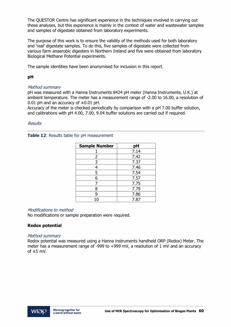
Use of MIR Spectroscopy for Optimisation of Biogas Plants 60
The QUESTOR Centre has significant experience in the techniques involved in carrying out these analyses, but this experience is mainly in the context of water and wastewater samples and samples of digestate obtained from laboratory experiments. The purpose of this work is to ensure the validity of the methods used for both laboratory and ‘real’ digestate samples. To do this, five samples of digestate were collected from various farm anaerobic digesters in Northern Ireland and five were obtained from laboratory Biological Methane Potential experiments. The sample identities have been anonymised for inclusion in this report. pH Method summary pH was measured with a Hanna Instruments 8424 pH meter (Hanna Instruments, U.K.) at ambient temperature. The meter has a measurement range of -2.00 to 16.00, a resolution of 0.01 pH and an accuracy of ±0.01 pH. Accuracy of the meter is checked periodically by comparison with a pH 7.00 buffer solution, and calibrations with pH 4.00, 7.00, 9.04 buffer solutions are carried out if required. Results
Table 12: Results table for pH measurement
Sample Number pH
1 7.14
2 7.42
3 7.37
4 7.46
5 7.54
6 7.57
7 7.75
8 7.79
9 7.86
10 7.87
Modifications to method No modifications or sample preparation were required. Redox potential Method summary Redox potential was measured using a Hanna instruments handheld ORP (Redox) Meter. The meter has a measurement range of -999 to +999 mV, a resolution of 1 mV and an accuracy of ±5 mV.

Use of MIR Spectroscopy for Optimisation of Biogas Plants 61
Results
Table 13: Results table for Redox potential measurement
Sample Number Redox potential (mV)
1 -315
2 -74
3 -114
4 -58
5 -46
6 -27
7 -365
8 -373
9 -99
10 -360
Modifications to method No modifications or sample preparation was required, although it was noted that the samples did take a long time for a stable value to be obtained. Ammoniacal Nitrogen Method summary Ammoniacal Nitrogen concentration was ascertained through use of Hach-Lange sensIONTM2 fitted with Ammonia Ion Selective Electrode (Isis Environmental, U.K.), capable of measuring NH4
+-N concentrations between 0.05 and 14,000 mg l-1 over a temperature range of 0 – 50°C. 25 ml of sample was adjusted to high pH through the addition of one Hach-Lange Ammonia Ionic Strength Adjustor (ISA) powder pillow. The ISA converts all ammonium to free nitrogen gas. The gas diffuses through the electrode membrane and causes a pH change in the electrode solution. The magnitude of the pH is proportional to the ammonia concentration in the solution being measured. The probe was calibrated before each use with 10 mg l-1 and 100 mg l-1 NH4
+-N standards. Results
Table 14: Results table for Total Ammonia measurement
Sample Number Total Ammonia as N (mg/l)
1 1610a
2 348
3 333
4 316
5 315
6 324
7 1300b
8 1135a
9 411
10 373 a – x2.5 dilution carried out, b- x5 dilution carried out

Use of MIR Spectroscopy for Optimisation of Biogas Plants 62
Modifications to method The method requires the sample to be stirred whilst stabilisation takes place, without this stirring action causing excessive vortex formation which can interfere with the reading. Some of the samples were too viscous to be stirred with a magnetic flea at a low rotational speed. To negate this issue, the viscosity was reduced with dilution with distilled water. The extent of dilution required was estimated by the experienced technical staff who work in the QUESTOR analytical laboratory. Total solids and volatile solids content Method summary A known volume of the sample is placed into a clean, dry crucible of known weight. The sample is then placed into a drying oven at 105 °C and dried approximately six hours to evaporate all free water. After drying, the crucible is allowed to cool to room temperature in a desiccator before being re-weighed. This weight is recorded and used to calculate total solids content. The crucible is then transferred to a muffle furnace at 550 °C and heated for 2 hours to drive off any volatiles. The crucible is then cooled to room temperature in a desiccator before being re-weighed. This weight is recorded and used to calculate volatile solids content. The total solids content is reported as a percentage by weight of the initial sample, and the volatile solids content is reported as a percentage by weight of the total solids. Results
Table 15: Results table for Total and Volatile Solids Content
Sample Number Total Solids (%) Volatile Solids (%)
1 7.51 77.75
2 1.26 53.11
3 1.36 48.47
4 1.29 52.90
5 1.56 41.47
6 1.24 49.64
7 5.74 75.04
8 6.39 71.33
9 2.03 58.49
10 3.89 70.62
Modifications to method No modifications to the standard method were required. Volatile fatty acids concentration Method summary Digestate samples were centrifuged at 12,000 rpm for 10 minutes. Volatile fatty acids (VFAs) concentration in the supernatant was then ascertained by use of a Perkin Elmer Autosystem XL Gas Chromograph fitted with a Shin Carbon ST micropacked column and an FID detector. An oven temperature of 40 °C was used and helium was used as the carrier gas.

Use of MIR Spectroscopy for Optimisation of Biogas Plants 63
VFA concentration was then determined by integration of the chromatogram peaks, in comparison to those peaks obtained with a 10 mmol VFA standard. The chromatogram for Sample 1 is shown as an example (Figure 26).
Figure 26: Example chromatograph for VFA determination
Results
Table 16: Results table for VFA determination
Sa
mp
le
Nu
mb
er
Ace
tic
Pro
pio
nic
Iso
bu
tryic
Bu
tryic
Iso
va
leric
n-V
ale
ric
Iso
ca
pro
ic
n-C
ap
roic
To
tal
de
tecte
d
Concentration (mg/l)
1 1621 635 89 188 97 1 8 3 2641
2 5 0 0 0 0 0 0 0 5
3 4 0 0 0 0 0 0 0 4
4 0 0 0 0 0 0 0 0 0
5 0 0 0 0 0 0 0 0 0
6 0 0 0 0 0 0 0 0 0
7 26 3 0 0 0 0 0 0 29
8 32 3 1 0 0 0 0 0 36
9 5 0 0 0 0 0 0 0 5
10 180 0 0 0 0 0 0 0 180

Use of MIR Spectroscopy for Optimisation of Biogas Plants 64
Modifications to method The more viscous nature of ‘real’ digestate samples in comparison to those taken from laboratory digesters led to issues with carryover of VFA compounds between injections. This was not observed until after Sample 1 was analysed, explaining in part the high concentration of organic acids detected. This issue was resolved by changing the solvent used to rinse the injection needle from distilled water to methanol, after which no further carry over was observed. Alkalinity/FOS-TAC ratio Alkalinity is a measure of the ability of a solution to neutralise acids. At different pH, different chemical species contained in a solution are responsible for the neutralisation of acids. The FOS/TAC ratio was developed in Germany as a useful parameter in the monitoring of biogas plants. FOS represents volatile organic acids (VFAs) and TAC represents total inorganic carbonate, which act as buffers against acid addition at different pHs. Method summary A representative sample is taken and course solids removed by filtering through a kitchen strainer. 20 ml of the filtrate is diluted as required and placed in a beaker and stirred with a magnetic stirrer. The sample is then titrated with 0.1 N H2SO4 to pH 5 and the volume of acid added noted (A). The titration then continues to pH 4.4 and the volume of acid added between pH 5 and 4.4 noted (B). The FOS/TAC ratio is then calculated using the empirical formula below:
(( ) )
Results
Table 17: Results table for FOS/TAC determination
Sample Number TAC titre (mls)
FOS titre (mls) FOS/TAC ratio
1 10.0 4.2 1.36
2 4.9 0.2 0.07
3 4.25 0.75 0.52
4 4.9 0.2 0.07
5 5.2 0.2 0.07
6 5.4 0.2 0.07
7 11.4 0.6 0.15
8 14.5 0.8 0.16
9 8.2 0.35 0.11
10 11.5 0.5 0.12
Modifications to method As with ammonia concentration determination, the viscosity of the samples was reduced through addition of distilled water. If the parameter of interest is FOS/TAC, this dilution does not have any effect as FOS/TAC is a ratio. However, if the FOS titre is being used to estimate total VFA concentration, then the dilution factor applied must be taken into account.

Use of MIR Spectroscopy for Optimisation of Biogas Plants 65
Recommendations The analyses of interest in the monitoring of biogas plants were successfully carried out on a number of digestate samples, with only minor deviations from the QUESTOR analytical procedures required. The methods involved were successfully verified. However, pH, redox potential and alkalinity are temperature and pressure dependent and samples should be therefore be analysed for these parameters immediately after collection. As this was not logistically possible for the analysis detailed here, the accuracy of these analyses cannot be guaranteed. To avoid this being an issue during the main project, dedicated equipment shall be made available on site. As it is unlikely that a person with experience in carrying out titrations will be available each time samples are collected, an automatic titrator should also be made accessible.

www.wrap.org.uk/diad