feasibility of a negative pressure system to remove … emergency vision assurance system...
TRANSCRIPT

Feasibility of a Negative Pressure System to Remove Smoke from an Aircraft
Flight Deck
by
Russell Davies
A Thesis Presented in Partial Fulfillment
of the Requirements for the Degree
Master of Science in Technology
Approved November 2013 by the
Graduate Supervisory Committee:
Bradley Rogers, Chair
Dale Palmgren
John Rajadas
ARIZONA STATE UNIVERSITY
December 2013

i
ABSTRACT
Smoke entering a flight deck cabin has been an issue for commercial aircraft for
many years. The issue for a flight crew is how to mitigate the smoke so that they can
safely fly the aircraft. For this thesis, the feasibility of having a Negative Pressure
System that utilizes the cabin altitude pressure and outside altitude pressure to remove
smoke from a flight deck was studied. Existing procedures for flight crews call for a
descent down to a safe level for depressurizing the aircraft before taking further action.
This process takes crucial time that is critical to the flight crew’s ability to keep aware of
the situation. This process involves a flight crews coordination and fast thinking to
manually take control of the aircraft; which has become increasing more difficult due to
the advancements in aircraft automation. Unfortunately this is the only accepted
procedure that is used by a flight crew.
Other products merely displace the smoke. This displacement is after the time it
takes for the flight crew to set up the smoke displacement unit with no guarantee that a
flight crew will be able to see or use all of the aircrafts controls.
The Negative Pressure System will work automatically and not only use similar
components already found on the aircraft, but work in conjunction with the smoke
detection system and pressurization system so smoke removal can begin without having
to descend down to a lower altitude. In order for this system to work correctly many
factors must be taken into consideration. The size of a flight deck varies from aircraft to
aircraft, therefore the ability for the system to efficiently remove smoke from an aircraft
is taken into consideration. For the system to be feasible on an aircraft the cost and

ii
weight must be taken into consideration as the added fuel consumption due to weight of
the system may be the limiting factor for installing such a system on commercial aircraft.

iii
DEDICATION
I would like to dedicate my Masters Thesis to my parents Ann and Barry as well
as my brothers Jon and Graham.
My father Barry, who’s spent 40 years working as an Electrical Engineer, has
taught and guided me through my schooling and career. My mother Ann, along with my
father, have both provided me with encouragement and support.
My Brothers Jon, an ASU Mechanical Engineering Technology student, and
Graham, an ASU Chemical Engineering Alum, have both supported and challenged me
with their knowledge to help push me forward to better myself.

iv
ACKNOWLEDGMENTS
I would like to thank all the Professors and faculty at ASU who have
helped guide me throughout my undergraduate and graduate studies in Mechanical
Engineering Technology to help get me to this point. Special thanks to Dr. Rogers for
encouragement and advice as an undergrad to get me into the graduate program and
subsequent guidance to help me complete my thesis. I would also like to thank Dr.
Rajadas and Dr. Palmgren for their time, effort, and enthusiasm to be my committee
members.
Lastly, I would like to thank all those I work with directly at US Airways and
indirectly through US Airways repair vendors and OEM suppliers. They have taught me
a great deal about the industry and aircraft systems. It is this knowledge I was taught
through work experience that I was able to develop this thesis topic.

v
TABLE OF CONTENTS
Page
LIST OF TABLES ………………………………………………………………..…….. vi
LIST OF FIGURES ………………………………………………………………….… vii
LIST OF ACRONYMS ………………………..…………………………………….... viii
CHAPTER
1 INTRODUCTION ………………………………………………………. 1
2 LITERATURE REVIEW ……………………………………………..… 4
3 METHODOLOGY …………………………………………………….. 12
4 RESULTS …………………………………………………………...…. 19
5 CONCLUSIONS & RECOMMENDATIONS ………………………… 23
REFERENCES ………………………………………………………………………… 25
APPENDIX
A BOEING 737-700/800 QUICK REFERENCE HANDBOOK (QRH)
SMOKE/FUME REOMVAL PROCEDURE ……...…………………... 28

vi
LIST OF TABLES
Table Page
1 Time of Useful Consciousness vs. Altitude..………………………...……...….. 19

vii
LIST OF FIGURES
Figure Page
1 Boeing Study of Smoke Events…..………………………………………...……. 2
2 FAA 20 Year Passenger Forecast ……………………………………..………… 3
3 Fatal Airline Accidents ………………………………………………..………… 5
4 O2 Mask Types ………………………………………………………..………… 6
5 IVU Removed from Container and Placed in Front of Captain ………...….……. 8
6 IVU Inflated to View Critical Flight Instruments ……………..……………..….. 8
7 Pilots Using IVU …………………………………………………..…………….. 9
8 Typical Aircraft Pressurization System Schematic ……………………….……. 13
9 Aircraft Pressurized Areas ……………………………………………………... 13
10 Cabin Altitude vs. Airplane Altitude ………………………………….……..… 15
11 Negative Pressure System Layout ………………….……………………..…… 18
12 QRH 737-700/800 Smoke Removal Procedure ………………………….......… 29

viii
LIST OF ACRONYMS
Acronym Page
NTSB National Transportation Safety Board ……………………………………….….. 2
FAA Federal Aviation Administration ……………………………………………..…. 2
InFO Information for Operators …………………………………….……………….… 4
EVAS Emergency Vision Assurance System ……………………….………………….. 7
IVU Inflatable Vision Unit …………………………………………………………… 7
QRH Quick Reference Handbook ……………………………..……………………... 10
AC Advisory Circular ………………………………………………………………. 10
CFR Code of Federal Regulations …………………………………………………… 10
ASD Aspirating Smoke Detector …………………………………………………….. 14
FAR Federal Aviation Regulation …………………………………………………… 16
CAQ Cabin Air Quality ………………………………………………………………. 17
EDS Energy-Dispersive Spectrometer ………………………………………………. 17
SEM Scanning Electron Microscope ………………………………………………… 18

1
CHAPTER 1
INTRODUCTION
Since the beginning of aircraft passenger travel, the aviation industry has made
much advancement in aircraft safety and reliability helping to ensure the flying public a
safe arrival to their destination if they so choose to travel by air. The advancement in
aviation safety has come from improved reliability of mechanical systems and also
improved avionics. The avionics of a modern aircraft have made the aircraft virtually
fully automated with airline pilots tending to only be manually flying the aircraft 90
seconds during take-off and 90 seconds during landing with the majority of flight being
controlled by automation. This automation has said to have diminished an airline pilot’s
skill and ability to make split second decisions to safely fly an airplane which has led to
the loss of control of an aircraft with catastrophic results [1]. Furthermore, the more
avionics installed on an aircraft increases the potential for an electronics fire.
Between November of 1992 and June of 2000, Boeing did a study showing that
the majority of events that resulted in smoke entering the aircraft were a result of
electronic system failures [2]. Figure 1 shows Boeing aircraft, listed in order of avionics
complexity, with the percentage of smoke events due to Electronic failures compared to
smoke from the air conditioning system and smoke caused by other materials. The air
conditioning smoke events were where smoke passed through the air conditioning ducts.
The smoke may have originated as a result of an event such as engine oil burning.
Materials smoke refers to items such as a coffee machine or an oven malfunction that
produced smoke.

2
Figure 1: Boeing Study of Smoke Events [2]
With the increases in automation, the avionics becomes a source of smoke and
fire. In part, due to this fire risk, the National Transportation Safety Board (NTSB) in
November of 2012 published their “Most Wanted List” with Improving Fire Safety in
Transportation as one of their top 10 issues [3]. One of the reasons to tackle the issue of
Fire Safety is that the Federal Aviation Administration (FAA) published their 20 year
Aerospace Forecast for Fiscal Years 2012-2032. The FAA study estimates that close to
500 million more passengers will fly annually by 2032 than in 2012 as depicted in Figure
2 below [4]. Airlines will have to compensate the increase in passengers with more
aircraft, thus increasing the potential for a smoke related event.

3
Figure 2: FAA 20 Year Passenger Forecast [4]
With the increase in amount of electrical equipment for automating the aircraft,
which in turn diminishes the pilot’s quick thinking ability, more aircraft flying, and the
NTSB’s push for Improving Fire Safety, there is a need to effectively remove smoke
from a flight deck. In doing so, the pilots can more easily stay calm and focused without
trying to view the aircraft instrumentation through a smoke filled flight deck. This
research will look at utilizing the pressure difference between the cabin and atmosphere
at cruising altitude to determine the feasibility of using a negative pressure system to
remove smoke from a flight deck.

4
CHAPTER 2
LITERATURE REVIEW
With advancements in avionics there is a potential for electrical failure such as
that of the Japan Airlines Boeing 787 at Boston’s Logan International Airport in January
of 2013; which was one of several events on the 787 that lead to the grounding of the
fleet by government officials [5]. This event however occurred while the aircraft was on
the ground and empty of passengers and crew. In many cases though, smoke events
occur while the aircraft is in flight which presents serious risk and danger to the
passengers and crew. In October of 2010, the FAA released an Information for Operators
(InFO) asking operators that experience a smoke or fumes event to collect the data for the
FAA so it can be tracked and determine trends. This is due to the fact that the FAA
Office of Accident Investigation and Prevention receives over 900 reports a year on
smoke or fumes in the cabin and or cockpit. The InFO stated that in a single day in April
of 2010, five aircraft had emergencies declared and diverted to the nearest airport due to
smoke or fumes [6]. Though the vast majority of reported events have no further
incident, tragically, smoke in the cockpit has been a cause of fatal aircraft crashes. In
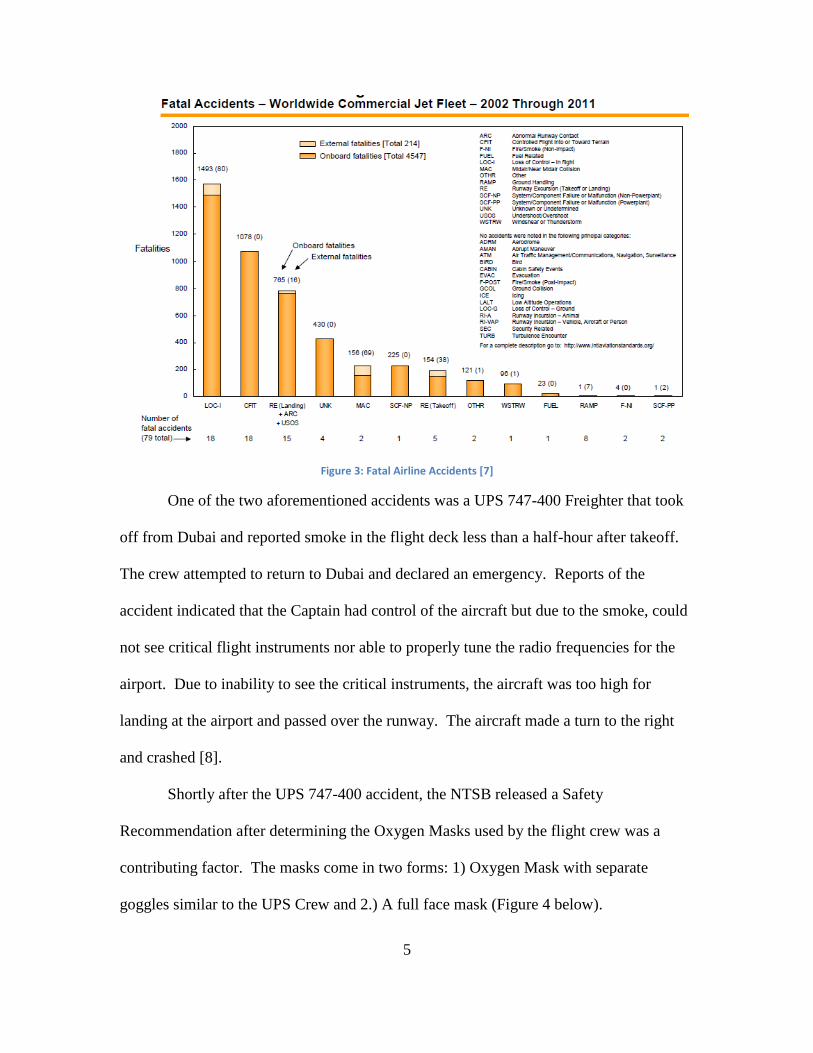
Figure 3 below from Boeings Statistical Summary of Commercial Jet Airplane Accidents,
there were 2 fatal accidents resulting in 4 losses of life between the years 2002 and 2011
[7].
5
Figure 3: Fatal Airline Accidents [7]
One of the two aforementioned accidents was a UPS 747-400 Freighter that took
off from Dubai and reported smoke in the flight deck less than a half-hour after takeoff.
The crew attempted to return to Dubai and declared an emergency. Reports of the
accident indicated that the Captain had control of the aircraft but due to the smoke, could
not see critical flight instruments nor able to properly tune the radio frequencies for the
airport. Due to inability to see the critical instruments, the aircraft was too high for
landing at the airport and passed over the runway. The aircraft made a turn to the right
and crashed [8].
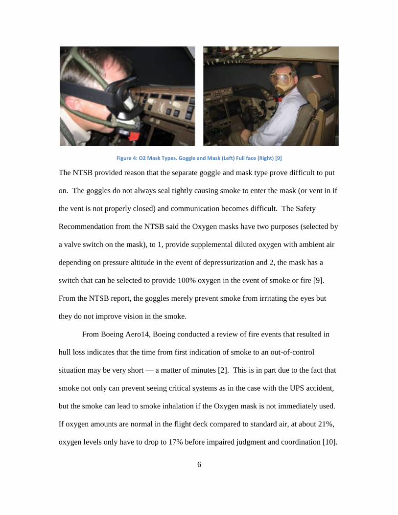
Shortly after the UPS 747-400 accident, the NTSB released a Safety
Recommendation after determining the Oxygen Masks used by the flight crew was a
contributing factor. The masks come in two forms: 1) Oxygen Mask with separate
goggles similar to the UPS Crew and 2.) A full face mask (Figure 4 below).
6
Figure 4: O2 Mask Types. Goggle and Mask (Left) Full face (Right) [9]
The NTSB provided reason that the separate goggle and mask type prove difficult to put
on. The goggles do not always seal tightly causing smoke to enter the mask (or vent in if
the vent is not properly closed) and communication becomes difficult. The Safety
Recommendation from the NTSB said the Oxygen masks have two purposes (selected by
a valve switch on the mask), to 1, provide supplemental diluted oxygen with ambient air
depending on pressure altitude in the event of depressurization and 2, the mask has a
switch that can be selected to provide 100% oxygen in the event of smoke or fire [9].
From the NTSB report, the goggles merely prevent smoke from irritating the eyes but
they do not improve vision in the smoke.
From Boeing Aero14, Boeing conducted a review of fire events that resulted in
hull loss indicates that the time from first indication of smoke to an out-of-control
situation may be very short — a matter of minutes [2]. This is in part due to the fact that
smoke not only can prevent seeing critical systems as in the case with the UPS accident,
but the smoke can lead to smoke inhalation if the Oxygen mask is not immediately used.
If oxygen amounts are normal in the flight deck compared to standard air, at about 21%,
oxygen levels only have to drop to 17% before impaired judgment and coordination [10].

7
This smoke then in turn may lead to Spatial Disorientation which is the mistaken
perception of one’s position and motion relative to the earth. Any condition that deprives
the pilots natural, visual references to maintain orientation can rapidly cause Spatial
Disorientation [11].
With the immediate danger that smoke presents an aircraft crew, there is a need
for a system to remove smoke from an aircraft flight deck. One such technology already
exists; which is a smoke displacement technology known as Emergency Vision
Assurance System (EVAS). This device is currently the only smoke displacement
technology enabling the pilots to see through the smoke [12]. The EVAS System is an
inflatable balloon like device, known as an Inflatable Vision Unit (IVU) that displaces
flight deck smoke by taking up the volume of space in the flight deck. When inflated
there is a viewing window on either end of the IVU with the intent that the flight crew
will be able to see directly through the IVU to the critical instruments [13]. The set-up of
the IVU is displayed in Figures 5-7 below.

8
Figure 5: IVU removed from container and placed in front of Captain [12]
Figure 6: IVU Inflated to view critical flight instruments [12]

9
Figure 7: Pilots using IVU [12]
The IVU, as shown in the above figures only covers the primary flight instruments but
does not cover engine instruments and controls, electronic panels and controls, overhead
panels, or circuit breakers [13]. This could be problematic for the Captain, as the
instruments that may display indications of what is causing the smoke, still can not be
seen. Furthermore, any attempt to stop a fire or smoke by turning off the engine controls,
electronic controls, or circuit breakers would also not be able to be done due to the IVU
not providing visibility paths to those areas of the flight deck and the bulkiness of the
IVU limiting the flight crews ability to maneuver around the flight deck. Further
downfall of the unit is that the IVU takes 30 to 60 seconds to inflate, which is in addition
to the time it takes the flight crew to locate the unit and set it up. In that time frame, the
flight deck may have filled with dangerous levels of the smoke while the crew waited
upwards of a minute for the IVU to inflate. Once inflated, the IVU also does not form

10
any air tight seal to the instruments or the flight crew. Therefore, smoke can still get
between the IVU and the instruments or the IVU and the flight crews goggles/mask. This
may still obstruct their vision, defeating the intent of the IVU. According to the
manufacturer of the Emergency Vision Assurance System (EVAS), VisionSafe, their list
of customers shows no major US airline having equipped their aircraft with EVAS [14].
In the event of smoke in the aircraft, commercial airlines will follow their Quick
Reference Handbook (QRH) for aircraft manufacturer approved procedures to attempt to
remove smoke. For example, the 737-800 QRH procedure (Appendix A), instructs the
flight crew to descend to below 14,000 feet and open the outflow valve. This will
depressurize the aircraft in an attempt to draw smoke out through the cabin – this is
essentially a “crude” Negative Pressure Smoke removal system in place today. In a worst
case scenario, the QRH authorizes the First Officer to open their window while
cautioning the effects of opening the window, such as noise levels [15]. This procedure
too has its downfalls, as first off it takes time to descend from upwards of 35,000ft to
40,000ft down to 14,000ft in a safe manner. Then the aircraft is depressurized to try and
rid the aircraft of smoke. Depressurization may cause aircraft structure issues and
passenger discomfort. Lastly, the procedure says to open a window, which the procedure
cautions about doing. This in itself could pose a danger to the flight crew with noise.
The QRH is however an accepted and practiced procedure by airlines. The FAA
released Advisory Circular (AC) 25-9A in 1994 for test procedures related to smoke and
fire on the aircraft [16]. This Advisory Circular references Code of Federal Regulation
(CFR) Title 14 – Aeronautics and Space, Part 25.831 which authorizes the use of
depressurization to evacuate smoke from the aircraft. This is the regulation that enables a

11
Negative Pressure System to remove smoke from an aircraft flight deck to be installed on
an aircraft.

12
CHAPTER 3
METHODOLOGY
With smoke and fume related incidents of nearly 900 being reported and the
Emergency Vision Assurance System (EVAS) currently the only marketed smoke
displacement system, there is a need for a viable flight deck smoke removal system
[6],[14]. With the regulations stating that the aircraft can be depressurized in an attempt
to remove smoke from the aircraft, a Negative Pressure System could be that viable
option [16].
The Negative Pressure System would expand on the existing Smoke Removal
Procedure of the Quick Reference Handbook (QRH) which allows for the opening of the
aircrafts pressurization control outflow valve at 14,000 feet [15]. This Negative Pressure
Control System would however enable the flight crew to safely evacuate the smoke from
the flight deck in a controlled manner while maintaining altitude.
What enables this is having a separate, isolated system from the current
pressurization system found on most commercial aircraft today. A schematic of an
aircraft’s pressurization system is depicted in Figure 8 where it shows the location of the
outflow valve at the aft end of the aircraft and the engine bleed system that provides the
air to the Air-Conditioning Packs, which pressurizes the cabin [17]. Figure 9 shows the
areas of the aircraft which are pressurized and the relation of the outflow valve to the
flight deck. If the outflow valve were to be opened to evacuate smoke from the flight
deck, the smoke would have to pass through the entire cabin area and the aircraft would
have to completely depressurize which would be inefficient.

13
Figure 8: Typical Aircraft Pressurization System Schematic [17]
Figure 9: Aircraft Pressurized Areas [17]

14
The Negative Pressure System for Flight Deck Smoke Removal will be an
automatic system, with manual overrides that will consist of a two valve system per side,
Captain and First Officer, a smoke detector system, a pressure sensor, an exhaust valve, a
filter system, and all items will be contained within a chamber.
The first component of the system is the smoke detection. A smoke detector, such
as an Aspirating Smoke Detector (ASD), would be used. The ASD uses an aspirating fan
to draw air through sampling pipes to detect smoke. This type of smoke detector
provides a higher than normal sensitivity allowing for earlier detection [18]. With the
ASD, the sampling pipes could be located in various places of a flight deck that smoke
may originate from which may provide earlier detection than a standard detector. The
smoke detection system would be tied into the aircrafts computer system. When the
smoke is sensed, the valve system for smoke removal will be triggered to operate
The valves for the system will be similar to that of the outflow valve already
found on pressurized aircraft. There will be two valves per side of the flight deck, the
Captains side and the First Officers side of the aircraft. The system will be identical for
both sides. The system will have one set of valves that will be located within the
pressurized area of the flight deck and the second set of valves on the fuselage. Each
valve will be connected by a duct/chamber area. Both sets of valves will be normally
closed. Therefore, when the aircraft pressurizes, the chamber area connected by the
valves will be isolated and thus unpressurized. When the smoke detection system
triggers the valve system, the valve in the flight deck will open and the differential
pressure between the flight deck and the chamber will cause the smoke to be drawn
through vents into the chamber. Aircraft typically fly with a cabin pressure to outside

15
pressure differential of about 8 PSI. As the aircraft altitude increases, the cabin altitude
increases, as shown in Figure 10, all the while maintaining the differential pressure of
about 8 PSI [17].
Figure 10: Cabin Altitude vs. Airplane Altitude [17]
The pressurization system of the aircraft through the opening and closing action
of the outflow valve will keep pressure changes to between 0.16PSI and 0.26PSI per
minute while the aircraft descends or ascends [17]. When the valves in the negative
pressure smoke system are activated, this is counteracting the work of the outflow valve
by causing sudden changes in cabin altitude. This is due to the opening of the first valve
to the chamber has increased the volume of the pressurized area of the aircraft by the now
pressurized volume of the chamber. This is addressed by having a pressure sensor
system in the chamber linked to the pressurization system of the aircraft.

16
When the first valve is opened to allow smoke to flow into the chamber, the
pressure sensors will determine the pressure between the chamber and the cabin. As the
pressure normalizes, the valve will shut. This will prevent the smoke from reentering the
flight deck. This will however likely cause an increase in cabin pressure altitude. For
example, Figure 10 shows a cabin altitude of about 8,000 feet when the aircraft is
cruising at 40,000 feet; by opening the valve to the smoke chamber, the cabin altitude
will raise. Though 8,000 feet is a comfortable level for passengers, Federal Aviation
Regulation (FAR) 91.211 does not require supplemental oxygen when the cabin pressure
altitude is below 12,500 feet [19]. Therefore, the pressure sensors would effectively
maintain safe cabin pressures but enough of a pressure differential between the cabin and
the chamber to draw smoke in. This is what allows for smoke removal process to begin
at cruise altitudes.
Once the pressure between the cabin and the chamber has normalized, the smoke
will be vented overboard by the opening of the second valve located on the exterior of the
fuselage. Similar to the way the smoke entered the chamber, the chamber is now
pressurized and at that 8PSI differential to the outside, thus the smoke will be vented
overboard. The placement of the exterior valve is however critical as to be above the
plane line of the engines. As smoke exits the aircraft, if it is not properly routed, it may
enter into the engines bleed air system and routed back into the aircraft cabin.
In an effort to maintain a safe aircraft cabin pressure altitude, the valve system,
identical on the Captain side and First Officers side, would alternate. That is, once the
system has been activated, the Captain’s side would first open the valve to draw smoke
into the chamber. Once the Captain’s first stage of the smoke removal cycle completes

17
with the valve in the flight deck closing and the second valve opening, the First Officer’s
side will begin with the valve in the flight deck opening. Thus, no two valves are open at
the same time but both sides are being utilized for sufficient smoke removal.
The system is automatic and will continue to cycle open and closed until no
smoke is detected or the flight crew has determined an issue and manually stops the
cycling of the system; which will reset the system and will automatically start again at the
next detection of smoke.
In the manner the flight crew can manually stop the cycling the system, the
system would also have a manual switch where a manual activation of the system will
cycle the system. Since this is a manual operation of the system, the pressure sensors
would cycle the valves sooner, as to not have as great of effect on the aircrafts cabin
altitude pressure.
A flight crew may want to manually operate the system for two reasons; one, if
smoke can be seen but the smoke detection system has had a failure and two, if there is
an odor present but no smoke. Since the bleed air from the engines provides air to the
air-conditioning PACK which is then recirculated for 50% fresh and 50% recirculated,
Cabin Air Quality (CAQ) has been an issue [17]. This manual activation will expel the
odor from the flight deck and the flight crew can then determine if it was an isolated
event or if the odor persists.
In the event the flight crew operated the system manually for odor, or even if it
was operated due to smoke, the system will have a filter element downstream of the first
valve contained within the chamber. These filters then can be removed for analysis using
such equipment as an Energy-Dispersive Spectrometer (EDS) for Scanning Electron

18
Microscope (SEM) Analysis [20]. Such an analysis can determine what the composition
of material was collected on the filter so an aircraft maintenance team can determine
where the odor and/or smoke may have originated from.
The final part of the system is an exhaust fan within the chamber. This fan will
aid in drawing smoke into the chamber which would be beneficial if the aircraft is at low
altitudes. If the aircraft is at low altitudes, the aircraft may not be pressurized meaning
the outflow valve for pressurizing the aircraft is open. However, since the aircraft is
unpressurized, there is no pressure differential to draw the smoke through the outflow
valve. The exhaust fan will provide the necessary means to remove any smoke from the
flight deck.
A layout of the Negative Pressure System is in Figure 11 below.
Figure 11: Negative Pressure System layout
19
CHAPTER 4
RESULTS
The use of a Negative Pressure System for Flight Deck Smoke Removal results in
the time saved for a flight crew to safely determine an issue with the aircraft prior to
descending. The significance of being able to remove the smoke at an altitude such as
35,000 feet as opposed to 14,000 feet is the significant amount of time a flight crew can
save to react and troubleshoot. From the FAA Advisory Circular 61-107A, an aircraft
cabin pressure would descend about 500 Feet Per Minute to prevent inner ear problems
for passengers and crew; this equates to about 14 minutes with cabin altitude at 8,000ft
when the aircraft is at 35,000ft and a cabin altitude of 1,000ft when the aircraft is at an
altitude of 14,000 feet [17], [21]. That 14 minutes of descend time could be critical if
there is a lack of oxygen due to the smoke and flight crews cannot react quickly enough
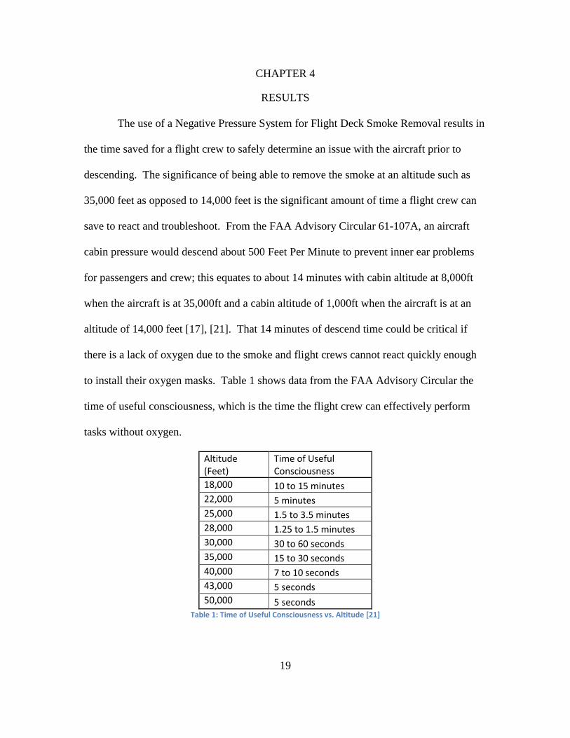
to install their oxygen masks. Table 1 shows data from the FAA Advisory Circular the
time of useful consciousness, which is the time the flight crew can effectively perform
tasks without oxygen.
Altitude (Feet)
Time of Useful Consciousness
18,000 10 to 15 minutes
22,000 5 minutes
25,000 1.5 to 3.5 minutes
28,000 1.25 to 1.5 minutes
30,000 30 to 60 seconds
35,000 15 to 30 seconds
40,000 7 to 10 seconds
43,000 5 seconds
50,000 5 seconds Table 1: Time of Useful Consciousness vs. Altitude [21]

20
Since there is only a matter of seconds to react to an event, it is imperative to have an
automatic system to remove smoke. This will provide precious amounts of time for the
flight crew to react. What enables this system to work effectively is a result of Boyle’s
Law. If it is assumed that at an instant in time, the amount of gas in the flight deck is
fixed and temperature is constant, the pressure and volume are inversely proportional
given in the equation as follows [22]:
p1V1 = p2V2
The volume, V2, would be equal to the volume of the flight deck, V1 plus the volume of
the chamber. Therefore, the equation becomes:
p1V1 = p2(V1+Vchamber)
This demonstrates that this increase in volume with the chamber will increase the
pressure in the flight deck.
Since the design of the system is based on smoke/air moving from the larger area
of the flight deck, into the smaller area of the chamber, and finally out into the
atmosphere, the design of the system can be modeled with a Venturi Effect. That is, as
the smoke passes through the constricted area from the flight deck to the chamber, the
pressure decreases and the velocity increases. This effect can be used to calculate
Volumetric Flow Rate, Q, as in the following equation [23]:
Q = v1A1 = v2A2
For this system, A1 would be the cross-sectional area of the flight deck and A2 the cross-
sectional area of the chamber. Since aircraft flight decks vary in size, A1 will change
based on aircraft type, therefore the system could be designed to meet the needs of a
smaller aircraft and thus have a smaller chamber area, A2. The flow rate would be
21
important in estimating the number of times the system would have to cycle to remove
the air from the flight deck. The rate at which smoke can effectively be removed from
the aircraft will be what determines how viable of a solution this Negative Pressure
System is to commercial aircraft.
Though the system may be beneficial, other factors affect the results in the
performance of the system. Since the system is based on utilizing the aircrafts
pressurization system, the system must do work in order to maintain pressurization. As
mentioned in the Methodology section for Figure 8, the engine bleed system provides the
air to the air-conditioning pack system. As the aircraft pressurizes, more air is needed to
be bled off the engine, resulting in less efficiency.
Another factor that decreases efficiency of the aircraft is weight and balance. The
system will require a substantial increase in weight to the aircraft. The weight and
balance is calculated by finding a moment of the added weight (in this case, the smoke
removal system) in relation to a datum line, which is calculated using the following
equation [24]:
M = Fd
With this system being located in the flight deck, it will be forward of the Center
of Gravity, which may alter flight characteristics slightly. The weight will have most
effect on fuel, as that is extra weight that will be carried by the aircraft.
Lastly, the system will have a noticeable effect on the aircraft because the second
valve will be in the fuselage skin to exhaust overboard. The cutout of the skin is critical;
however, the installation of the valve in the placement of the cutout negates the structural
effect of the cutout. However, from the Boeing Fuel Conservation – Airframe

22
Maintenance for Environmental Performance, excrescence drag, which is the drag on the
airplane due to deviations from the smooth external surface, can make the aircraft less
efficient. A 1% increase in drag on a Boeing 767 for example can increase fuel
consumption by 30,000 gallons per year. Boeing states that the forward area of an
aircraft’s fuselage is a critical area and requires a high degree of aerodynamic smoothness
[25]. The second valve to exhaust smoke overboard then becomes critical in its location
on the aircraft as to reduce the aerodynamic effect.
The aerodynamic effect of the valve may have a long term economical effect with
the cost of fuel for a commercial aircraft. This is in addition to the additional costs that
would be involved with the complexities of integrating a new system into the aircraft.
The design, testing, implementation, and subsequent maintenance of a Negative Pressure
System for Flight Deck Smoke Removal will likely result in a high financial cost.

23
CHAPTER 5
CONCLUSIONS & RECOMMENDATIONS
With the significant amount of reports of smoke and fumes being reported in
commercial aircraft, there is a need to address this issue. The advancements in aviation
technology have seen both its pros and cons. The advanced technology has made flying
overall more reliable and more efficient. The drawback however is that pilot skills are
dulled by automation and the electronics needed for the automation increases fire
potential. This fire potential has led to some recent development in technology that could
be beneficial to a flight crew without increasing their work load.
The advantage of having an automatic Negative Pressure System to remove
smoke from a flight deck is that the system would be designed in such a way that a pilot
would not have to descend to a lower altitude to begin the process of removing smoke
from the flight deck. This buys the flight crew precious time to make critical decisions to
determine the cause and extent of danger from any smoke. By being able to operate the
system at altitude, there is also no need to do an emergency descent to depressurize the
cabin. This preserves passenger comfort and prevents any serious effects of rapid
decompression on the aircraft structure.
The primary advantage is that this is the only system that would remove smoke
from a flight deck whereas others merely disperse the smoke. By being able to
successfully remove smoke from the flight deck, it prevents smoke from building up
which may prevent a flight crew from viewing critical instruments. In order for a flight
crew to maintain safe flight, they need to be able to easily see these critical instruments
24
and be able to easily access all controls they may need as they make quick decisions on
how to handle the emergency.
The disadvantages of the system are going to be that the complete system will
have to be incorporated into the aircraft design. This will require additional weight,
structural changes, increases in drag, electrical power, and changes to the aircraft
computer system so the systems can integrate together. This will come at a high cost and
may only be suitable for new production aircraft. Any type of retrofit system to existing
aircraft may be cost prohibitive. Therefore, the system would only have a very small
market share of the world’s aircraft population; thus not making a significant impact.
With no smoke removal technology for commercial aircraft available, only smoke
displacement, it is recommended to further study how smoke can effectively be removed
from an aircraft. It is recommended to investigate all aircraft types as designing a system
around one aircraft type may not be practical due to the variations in aircraft size and the
performance of the aircraft – which could affect cabin altitude pressure and the altitude it
cruises at. Though the number of catastrophic accidents due to smoke in the flight deck
are relatively low; the growth of aircraft travel will dictate the need for a system such as
the Negative Pressure System to Remove Smoke from an Aircraft Flight Deck.

25
REFRENCES
[1] Joan Lowy. (2011, August) AP IMPACT: Automation in the Air Dulls Pilot Skill.
[Online]. http://www.deseretnews.com/article/700174876/AP-IMPACT-
Automation-in-the-air-dulls-pilot-skill.html
[2] Morton, J. (2001, April). Flight and Cabin Crew Response to In-flight Smoke.
Boeing Aero. 3-10.
[3] National Transportation Safety Board. (2012, November). Improve Fire Safety in
Transportation. [Online]. http://www.ntsb.gov/safety/mwl4_2012.html
[4] Federal Aviation Administration. (2012, March). FAA Aerospace Forecast Fiscal
Years 2012 – 2023. [Online].
http://www.faa.gov/about/office_org/headquarters_offices/apl/aviation_forecasts/
aerospace_forecasts/2012-2032/
[5] Topham, J. (2013, January). Boeing Dreamliners Grounded Worldwide on
Battery Checks. [Online]. http://www.reuters.com/article/2013/01/17/us-boeing-
dreamliner-idUSBRE90F1N820130117
[6] Federal Aviation Administration. (2010, October). InFO 10019 – Information For
Operators; Smoke/Fumes in the Cabin/Cockpit of Transport Category Aircraft.
[Online].
http://www.faa.gov/other_visit/aviation_industry/airline_operators/airline_safety/i
nfo/
[7] Boeing. (2011). Statistical Summary of Commercial Jet Airplane Accidents 1959-
2011. [Online]. http://www.boeing.com/news/techissues/pdf/statsum.pdf
[8] Basusta, U. (2008, November). UPS Cargo Boeing 747Crashes. [Online].
http://www.airnewstimes.co.uk/unal-basusta-ups-cargo-boeing-747-crashes-240-
article.html
[9] National Transportation Safety Board. (2011, September). Safety
Recommendation A-11-87-91. [Online].
http://www.ntsb.gov/doclib/recletters/2011/a-11-087-091.pdf
[10] National Fire Protection Association. (2013, January). The Consequences of
Fire. [Online].
http://www.nfpa.org/itemDetail.asp?categoryID=1367&itemID=31834&URL=
Press%20Room/A%20Reporter%27s%20Guide%20to%20Fire%20and%20the
%20NFPA/The%20consequences%20of%20fire&cookie_test=1
[11] Wynbrandt, J. (2004, August). Spatial Disorientation – Confusion that Kills.
AOPA Safety Advisor. 1-10.

26
[12] RAESE Group. (2012, October). Smoke Displacement Technology – A Vital
Insurance Policy. [Online]. http://www.raesegroup.com/2012/10/09/smoke-
displacement-technology-a-vital-insurance-policy/
[13] Vision Safe. (2009, June). EVAS Training Outline. [Online].
http://www.visionsafe.com/VisionSafe.com/Content/docs/Classroom%20hando
ut%20022713.pdf
[14] Vision Safe. (2013, February). EVAS Equipped Operators. [Online].
http://www.visionsafe.com/operators.html
[15] Copa Airlines. (2009, October). B737-700/800 Quick Reference Handbook.
[Online]. http://cmpva.org/manops/quick%20reference%20manual%20B737-
70025.pdf
[16] Federal Aviation Administration. (1994, January). Advisory Circular 25-9A –
Smoke Detection, Penetration, Evacuation Tests and Related Flight Manual
Emergency Procedures. [Online].
http://www.faa.gov/regulations_policies/advisory_circulars/index.cfm/go/docu
ment.information/documentID/22464
[17] Hunt, Elwood., Reid, Don., Space, David., Tilton, Fred. (1995). Commercial
Airliner Environmental Control System. Engineering Aspects of Cabin Air
Quality, 1-8.
[18] Air Sense Technology. (2013, January). Aspirating Smoke Detection – A Brief
Guide for the Designer. [Online].
http://www.airsensetechnology.com/documents/guides/brief_guide.pdf
[19] Federal Aviation Administration. (2012, November). Code of Federal
Regulations – FAR 91.211. [Online].
http://rgl.faa.gov/Regulatory_and_Guidance_Library/rgFAR.nsf/0/ba9afbf96db
c56f0852566cf006798f9!OpenDocument
[20] EDAX Smart Insight. (2011, March). EDS for SEM Analysis. [Online].
http://www.edax.com/Products/EDS/TEAM/TEAM-EDS-SEM-Analysis-Phase-
mapping-Spectra-collection.aspx

27
[21] Federal Aviation Administration. (2003, January). Advisory Circular 61-107A –
Operations of Aircraft at Altitudes Above 25,000 Feet MSL and/or MACH
Numbers (MMO) Greater than 0.75. [Online].
http://www.faa.gov/pilots/training/airman_education/media/ac%2061-107a.pdf
[22] Think Quest. (2013, February). Boyles Law. [Online].
http://library.thinkquest.org/12596/boyles.html
[23] Western Washington University Physics Net. (2013, January). Volumetric Flow
Rate. [Online].
http://faculty.wwu.edu/vawter/PhysicsNet/Topics/Pressure/VolumeFlowRate.ht
ml
[24] Federal Aviation Administration (2005, June). Advisory Circular 120-27E –
Aircraft Weight and Balance Control. [Online].
http://www.faa.gov/regulations_policies/advisory_circulars/index.cfm/go/docu
ment.information/documentID/22749
[25] International Civil Aviation Organization. (2006, September). Fuel
Conservation Airframe Maintenance for Environmental Performance. [Online].
http://www.icao.int/Meetings/EnvironmentalWorkshops/Documents/ICAO-
TransportCanada-2006/Anderson.pdf

28
APPENDIX A
BOEING 737-700/800 QUICK REFERENCE HANDBOOK (QRH)
SMOKE/FUMES REMOVAL PROCEDURE

29
Figure 12: 737-700/800 QRH Smoke Removal Procedure [15]