feasibility and limits of wi-fi imaginggshyam/papers/wision.pdf · feasibility and limits of wi-fi...
TRANSCRIPT
Feasibility and Limits of Wi-Fi Imaging
Donny Huang†, Rajalakshmi Nandakumar†, Shyamnath GollakotaUniversity of Washington
donnyhuang, rajaln, [email protected]†Co-primary Student Authors
AbstractWe explore the feasibility of achieving computational
imaging using Wi-Fi signals. To achieve this, we leveragemulti-path propagation that results in wireless signals bounc-ing off of objects before arriving at the receiver. These re-flections effectively light up the objects, which we use to per-form imaging. Our algorithms separate the multi-path reflec-tions from different objects into an image. They can also ex-tract depth information where objects in the same direction,but at different distances to the receiver, can be identified.We implement a prototype wireless receiver using USRP-N210s at 2.4 GHz and demonstrate that it can image objectssuch as leather couches and metallic shapes in line-of-sightand non-line-of-sight scenarios. We also demonstrate proof-of-concept applications including localization of static hu-mans and objects, without the need for tagging them withRF devices. Our results show that we can localize static hu-man subjects and metallic objects with a median accuracy of26 and 15 cm respectively. Finally, we discuss the limits ofour Wi-Fi based approach to imaging.
Categories and Subject DescriptorsC.2.1 [Network Architecture and Design]: Wireless
Communication
KeywordsWireless sensing, Wi-Fi imaging
1 IntroductionIs it possible to leverage Wi-Fi signals to create images
of objects and humans? Given the ubiquity of Wi-Fi signals,a positive answer would allow us to localize static humanseven when they do not carry any RF devices, thus enablingpervasive home sensing. It would also enable new applica-tions such as inventory localization — objects such as cartscan be tracked without either the need for tagging them withRF sources or the burden of installation and cost that make
Permission to make digital or hard copies of all or part of this work for personal orclassroom use is granted without fee provided that copies are not made or distributedfor profit or commercial advantage and that copies bear this notice and the full citationon the first page. To copy otherwise, to republish, to post on servers or to redistributeto lists, requires prior specific permission and/or a fee.
SenSys’14, November 3–6, 2014, Memphis, TN, USA.Copyright c© 2014 ACM 978-1-4503-1169-4 ...$10.00
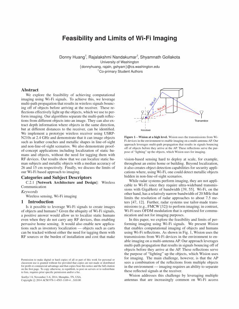
Figure 1—Wision at a high level. Wision uses the transmissions from Wi-
Fi devices in the environment to enable imaging on a multi-antenna AP. Our
approach leverages multi-path propagation that results in signals bouncing
off of objects before they arrive at the AP. These reflections serve the pur-
pose of “lighting” up the objects, which Wision uses for imaging.
vision-based sensing hard to deploy at scale, for example,throughout an entire home or building. Beyond localization,it also creates object detection capabilities for security appli-cations where, using Wi-Fi, one could detect metallic objectshidden in non-line-of-sight scenarios.
While radar systems perform imaging, they are not appli-cable to Wi-Fi since they require ultra-wideband transmis-sions with GigaHertz of bandwidth [39, 55]. Wi-Fi, on theother hand, has a relatively narrow bandwidth of 20 MHz thatlimits the resolution of radar approaches to about 7.5 me-ters [47, 12]. Further, radar systems use tailor-made trans-missions (e.g., FMCW [32]) to perform imaging; in contrast,Wi-Fi uses OFDM modulation that is optimized for commu-nication and not for imaging purposes.
In this paper, we explore the feasibility and limits of per-forming imaging using Wi-Fi signals. We present Wisionthat enables computational imaging of objects and humansusing Wi-Fi reflections. As shown in Fig. 1, Wision uses thetransmissions from Wi-Fi devices in the environment to en-able imaging on a multi-antenna AP. Our approach leveragesmulti-path propagation that results in signals bouncing off ofobjects before they arrive at the AP. These reflections servethe purpose of “lighting” up the objects, which Wision usesfor imaging. The main challenge, however, is that the APsees a combination of the reflections from multiple objectsin the environment — imaging requires an ability to separatethese reflected signals at the receiver.
Wision addresses this challenge by leveraging multipleantennas that are increasingly common on Wi-Fi access

Figure 2—Example image created by Wision. The figure shows the image
captured by Wision of a T-shaped metallic object.
points. Wi-Fi APs today come with an ever-increasing num-ber of antennas; 16-32 sectorized antenna Wi-Fi APs are al-ready available on the market [3]. Further, there is a push inthe academic community to provide higher network capac-ity by using large-scale MIMO APs with tens to hundreds ofantennas [52, 45, 22].
To understand Wision, consider the wireless signals re-ceived by the two-dimensional antenna array shown in thefigure. The Wision receiver leverages angle-of-arrival tech-niques to construct an image that separates the reflectionsfrom each azimuthal and elevation angle. Specifically, Wi-sion performs a 2D-FFT operation to separate the multi-pathreflections on its antenna array. Intuitively, a signal froman azimuthal and elevation angle results in a specific patternof phase differences across the receive antennas. Since dif-ferences in phase translates into a frequency, each azimuthaland elevation angle corresponds to a specific frequency com-ponent at the receiver. Thus, by computing an FFT, the re-ceiver can separate these signals. Wision then constructs animage by measuring the intensities of the multi-path reflec-tions from each azimuthal and elevation angle.
Wision also goes beyond the capabilities of traditional op-tical cameras, and extracts the depth information. Specifi-cally, since the above FFT operation produces a single in-tensity value per direction (azimuthal and elevation angle),it cannot distinguish two objects that lie at different depthsalong the same direction to the receiver. Wision extracts thisdepth information by performing beamforming at the wire-less transmitter. Intuitively, beamforming changes the regionof space that is illuminated by wireless signals and henceenables the receiver to focus on reflections from differentdepths along the same azimuthal and elevation angles. Thus,a Wision receiver computes the intensity values for differenttransmit beamforming directions and stitches them togetherto image objects that lie along different depths. In the restof the paper, we expand on the above idea and demonstratehow to image objects in both line-of-sight and non-line-of-sight scenarios. We also extend our approach to work withone-dimensional antenna arrays and describe our algorithmto combine images across multiple wireless transmitters.
Wision is related to recent work on motion detectionusing Wi-Fi Doppler [14, 38, 19]. These systems extractthe minute changes in the Wi-Fi signals caused by humanmotion such as running [14], walking forward and back-ward [19], and gestures [38]. While we build on this work,Wision is the first system that leverages narrowband signal(e.g., Wi-Fi) reflections to create images of static objects inthe environment.
To show the feasibility of our approach, we implement aWision receiver on USRP-N210s operating at 2.4 GHz usingthe phase and amplitude of the first OFDM data sub-carrier.We evaluate the effects of various properties of objects, in-cluding size, material, and orientation, on their interactionwith Wi-Fi signals. We present imaging results using variousreceiver configurations ranging from 4× 1 to 8× 8 antennaarrays. We experiment in various line-of-sight and non-line-of-sight scenarios where the object is separated from both thetransmitter and the receiver. Our results show the following:• Using two-dimensional antenna arrays, Wision could cre-
ate images of a metallic T-shaped structure, similar toFig. 2. The object’s length and height in the resulting im-age are within 5 and 8 cm, and 18 and 40 cm of the actualobject, using 8×8 and 4×4 antenna arrays respectively.
• Wision’s imaging capability extends to common objectssuch as leather couches and in non-line-of-sight scenarioswhere the object is separated from the transmitter and thereceiver by a barrier 4 cm thick.
• The imaging capability however is limited by the materialof the object: metallic surfaces reflect better than woodensurfaces, which in turn reflect better than foam. Also, theimaging ability reduces with the object’s size: objects thatare smaller or comparable to the wavelength of the wire-less signals have very weak interactions making them dif-ficult to image. Finally, the blurriness of the images (asseen in Fig. 2) is dependent on the signal wavelength andis inherent to imaging using Wi-Fi signals.
We also perform feasibility studies of three applications:static human localization, object localization, and through-the-fabric detection of metallic objects. Our results show thefollowing about Wision:• It localizes static humans with a median accuracy of
26 cm, even in the presence of motion from other humansin the environment.
• It localizes a HP desktop with a median accuracy of15 cm, in an office environment with other furniture.
• It could detect a passive MacBook Pro placed in a back-pack and a passive smartphone placed in the pocket of ahoodie worn by a human subject.
Contributions: We explore the feasibility of imaging usingnarrow band signals (e.g., Wi-Fi) by leveraging the multi-path reflections. To do this, we show how to extract the in-tensities of the wireless reflections from different azimuthaland elevation angles by leveraging multiple-antennas at theAP. We also introduce mechanisms that extract the depth in-formation using transmit beamforming. We build a prototypeand demonstrate its ability to create images in both line-of-sight and non-line-of-sight scenarios. Finally, we discuss thelimits of our Wi-Fi based approach to imaging.
2 Related WorkOur work is related to prior art in two domains.
(a) Wi-Fi Systems: The related work in this domain falls intwo main areas: Wi-Fi localization and device-free motiondetection. There has been significant work on Wi-Fi devicelocalization [8, 53] using techniques including RSSI [15, 48]and fine-grained channel state information [44]. The stateof the art systems [7, 21, 51] achieve sub-meter localiza-

tion accuracies using statistical angle-of-arrival techniquessuch as MUSIC [43]. More recently work on motion de-tection [38, 19, 28, 14, 42, 46] uses changes to the wirelesssignals caused by human motion such as running [14], walk-ing forward and backward [19], body gestures [38, 28], andactivity recognition [42, 46]. Wision goes beyond these de-vice localization and motion detection systems and enablesimaging of static objects and humans.
(b) RF Image Sensing: Traditional radar systems havebeen used to perform human motion and activity detec-tion [4, 40, 31, 34, 5, 18, 29] and detection of static metallicobjects [13, 39, 49, 55, 27]. These systems however use ex-pensive ultra-wideband transceivers, multiple antennas, andspecialized signal modulation (e.g., FMCW [32]). Specif-ically, [13, 39, 49] use 500 MHz to 3 GHz wideband trans-missions to detect human motion and image metallic objects.Wision instead performs imaging of objects using narrow-band wireless transmissions (e.g., Wi-Fi). Further, Wisionachieves this using the channel amplitude and phase infor-mation from Wi-Fi OFDM transmissions, instead of requir-ing special modulated signals (e.g., FMCW).
Wision is also related to recent proposals [10, 35] thatuse techniques like compressive sensing with single-antennadevices and full-duplex radios to detect the presence of anyobject in a sparse environment. In contrast, Wision addressesthe more general problem of transforming Wi-Fi into a cam-era that creates images of objects. We also build a prototypeof Wision and show that it can image and localize objectsand humans in line-of-sight and non-line-of-sight scenarios.
Wision also builds on foundation work on radio tomog-raphy imaging [54, 50, 37]. These systems track humanmotion including fine-grained breathing motion by deploy-ing ten to thirty sensors spread throughout the environ-ment and measuring the channel attenuation between everypair of sensors. Recent work also creates images of ob-jects using robotic Wi-Fi transmitter-receiver pairs that movearound the object of interest to measure its absorption prop-erties [36, 23, 24]. Wision differs from this line of work intwo ways: First, our goal is to use static Wi-Fi infrastructureto enable sensing and imaging applications using few Wi-Fitransmitters, without the need for multiple sensors or roboticdeployments. To achieve this we leverage multiple antennasto extract the object reflections in the environment. Second,tomography systems [36, 24] use wireless absorption prop-erties of the objects for imaging. In contrast, we use wirelessreflections and scattering to perform imaging, and hence re-quire a different set of algorithms.
Finally, our work builds on prior work in MRI, optical,microscopy, and computational photography. In contrast tothis work, we focus on exploring the feasibility of imagingusing OFDM based signals that are commonly used in wire-less communication systems (e.g., Wi-Fi).
3 Wision OverviewWision is a novel approach to imaging using narrowband
wireless signals (e.g., Wi-Fi). It leverages transmissionsfrom Wi-Fi devices in the environment to perform imagingon the AP. Wireless transmissions experience multi-path re-flections that effectively ”light up” reflective objects in the
Figure 3—Overview of Imaging Radar Approaches. The transmitter
sends a very narrow pulse and the receiver computes the intensity of the
region R by measuring the pulse echoes from distances of d00 · · ·dnn at the
antenna elements. This requires ultra-wideband transmissions that is not
applicable to Wi-Fi signals.
environment, which the Wision receiver uses to image theobjects. Wision leverages multiple antennas at the receiverand is designed to be implemented on a Wi-Fi AP. The trans-mitters can be either mobile devices, like smartphones andlaptops, or other APs on the same Wi-Fi channel. In the restof this section, we first provide an overview of imaging radarapproaches. We then describe the advantages and challengesof using Wi-Fi over radar imaging.
3.1 Overview of Radar ApproachesRadar systems operate by transmitting a short narrow
pulse and waiting for the pulse to hit an object and returnback. They then compute the time difference between thetwo events to estimate the distance from the object. Fromradar theory, to distinguish two objects that are separated by∆d, the duration of the pulse, ∆p, must satisfy [47]:
∆p ≤2∆d
c0
where c0 is the speed of the wireless signals. The aboveequation states that to distinguish two close-by objects, thelength of the pulse must be short. This is expected becausethe echoes of longer pulses merge together and make it dif-ficult to identify the echoes as two separate objects. Sinceshorter pulses occupy wider bandwidth, radar approaches re-quire a large bandwidth to distinguish objects in the environ-ment. For instance, achieving a resolution of 50 cm requiresa transmission bandwidth of 300 MHz.
Imaging radar systems (e.g., SAR [20, 12]) leverage theabove approach to create an image. Specifically, these sys-tems use antenna arrays (or equivalently, moving antennas)as the receiver, as shown in Fig. 3. To compute the inten-sity of a particular region R, the receiver measures the pulseechoes on each of the antennas from distances of d00, · · · ,dnn,as shown in the figure. The receiver then coherently com-bines these echoes across all its antennas to compute an in-tensity value for R. By repeating this procedure across re-gions, radar systems create an image of the space.
Note that the resolution of the radar imaging is deter-mined by its ability to compute accurate distance measure-ments from each of the receive antennas; this requires narrowpulses that use ultra-wideband transmissions. We note thatmany practical radar systems use specialized signals (e.g.,

FMCW [32, 39]); these systems however still need similarultra-wideband transmissions to perform imaging.
3.2 A Case for Using Wi-Fi over Radar Imag-ing
Using Wi-Fi over radar for imaging is attractive for twomain reasons: First, the cost of a Wi-Fi chipset is signifi-cantly lower than a radar device given its economy of scaleand lower bandwidth requirements. Thus, a Wi-Fi imag-ing solution would enable imaging capabilities at a muchlower cost than radar-based solutions. Second, for the samepower level, mono-static radar systems (where the transmit-ter and the receiver are co-located) have a much lower rangeof operation than bi-static radar systems (where the trans-mitter and receiver are separated in distance) [38]. Thusto achieve a good range (e.g., a whole-home coverage), theradar transmitter-receiver pair should be separated and de-ployed at different locations. Further, reliable wireless imag-ing requires deploying multiple radar transmitters at variousangles with respect to the object. In contrast, Wi-Fi devicesare already spread out in the environment, and hence natu-rally provide a good imaging range as well as light the objectfrom various angles to provide reliable imaging.
3.3 Challenges Using Wi-Fi for ImagingWi-Fi transmissions impose significant constraints that
make it challenging to leverage radar imaging approaches:• Wi-Fi has orders of magnitude lower bandwidth than is
required for radar imaging. Typical Wi-Fi transmissionsoccupy a bandwidth of 20 MHz; a radar system with a20 MHz bandwidth provides a maximum resolution of7.5 meters, which is inadequate for imaging purposes. Wealso note that while the above distance-based radar sys-tems use multiple antennas, they require accurate compu-tation of the distance values from an object of interest toeach of its antennas.
• Wi-Fi signals are OFDM-based transmissions that are notdesigned for imaging purposes. Our goal is to lever-age transmissions from Wi-Fi devices in the environment.Thus, we cannot use custom radar signal waveforms in-cluding narrow pulse transmissions and FMCW signals.1
We also note that the channel state information [25] isincreasingly becoming accessible on Wi-Fi devices; thus,it is desirable to have an imaging solution that uses onlythe channel amplitude and phase information.
4 Wision DesignTo avoid the above challenges, Wision creates images us-
ing a different principle than that of radar systems. Wision’sapproach is similar in spirit to optical imaging systems whereimages are typically formed by measuring the incoming sig-nal intensities at each azimuth and elevation angle. Thisavoids the need for distance computation and hence is notconstrained by the requirements of traditional radar systems.
Achieving this in practice is, however, not straightforwardbecause the receiver receives the combination of reflectionsfrom multiple regions in space on each of its antennas. In a
1 In contrast to Wi-Fi that uses OFDM, FMCW signals use hundreds
of megahertz/GHz bandwidth and sweep the frequency across time; pulse
radar signals send very narrow pulse in time.
Figure 4—Calculating the phase difference between antenna Anm and
A00. For the signal S(ψ,α), the difference in the received phase between
Anm and A00 is related to the additional distance ∆dnm(ψ,α) that S(ψ,α)travelled to reach Anm.
optical system, a lens is used to physically separate the re-ceived signals from different directions. Wision, in contrast,uses multiple antennas and Fourier analysis to separate thesesignals. In the rest of this section, we first describe our im-age construction algorithm using a two-dimensional antennaarray at the receiver. We then extend our design to work withsingle-antenna arrays. Next, we describe how we combineimages across multiple transmitters. Finally, we outline ouralgorithm to extract depth using transmitter beamforming.
4.1 Wision’s Imaging Algorithm
As shown in Fig. 4, Wision performs imaging using multi-ple antennas at the Wi-Fi receiver. We first show that the sig-nal from each azimuthal and elevation angle corresponds toa specific pattern of phase differences (i.e., a basis function)across the antennas. We then describe how Wision extractsthe multi-path intensities at different azimuthal and elevationangles by performing a Fourier transform.
4.1.1 Mapping directions to basis functions
The received signal is a linear combination of the multi-path reflections from different directions (i.e., azimuthaland elevation angles). Consider the multi-path reflection,S(ψ,α), arriving at the receiver from an azimuthal angle ψand an elevation angle α. These reflections correspond tospecific phase differences across the antennas at the receiver.
To see this, consider the antenna array along the x-y plane,Fig. 4, where the antenna, A00, is located at the origin. Saythat the antennas are each separated by d and that there area total of N and M antennas along the x-axis and y-axis re-spectively. We compute the phase difference between theantenna-pair, Anm and A00. From basic physics, the phasechange in a complex wave as it traverses a distance ∆d is
given by ej 2π∆dλ , where λ is the signal wavelength. Thus, the
phase change, experienced by the signal S(ψ,α) is given by:
ej2π∆dnm(ψ,α)
λ (1)
where ∆dnm(ψ,α) is the extra distance traversed by the signalbetween A00 and Anm, as shown in the figure. Using trigono-metric identities, we derive the following equations that are

(a) ψ = 0,α = 0 (b) ψ = 30,α = 0 (c) ψ = 60,α = 0 (d) ψ = 60,α = 30
Figure 5—Basis functions for various azimuthal (ψ) and elevation angles (α). Signals incoming from different azimuthal and elevation angles correspond
to basis functions of differing frequencies and orientations. Treating the incoming signals as a combination of basis functions enables efficient operations, such
as the 2D-FFT, to be performed upon them.
satisfied in the figure:
∆dnm(ψ,α) = ‖~Anm‖cos(γ)
cos(γ) =~S(ψ,α) ·~Anm
‖ ~S(ψ,α)‖‖~Anm‖
where ~Anm is the vector from the origin to the antenna ele-
ment Anm,~S(ψ,α) is the vector corresponding to the signal,S(ψ,α), and the (·) operation computes the dot product be-tween two vectors. Now, given that the antenna array Anm isat position (nd,md,0), where d is the distance between the
antennas,~Anm can be written as,
~Anm = [nd,md,0]T
Similarly, since the signal S(ψ,α) arrives at the receiveralong the azimuthal angle ψ and elevation angle α, we havethe unit vector corresponding to the signal S(ψ,α) as,
~S(ψ,α)
‖~S(ψ,α)‖= [cos(α)cos(ψ), sin(α), cos(α)sin(ψ)]T
Combining all the above equations, we can rewrite the phasechange between antennas, Anm and A00 in Eq. 1 as,
ej(nd cos(α)cos(ψ)+md sin(α))
Now if we define the basis function of the signal arrivingfrom an azimuthal angle ψ and elevation angle α, Bψ,α, asthe pattern of phase differences from all the antennas to A00,we can write the basis function as the following matrix:
Bψ,α = [ej(nd cos(α)cos(ψ)+md sin(α))]n,m
The above equation states that the basis function changeswith the azimuthal and elevation angles, which we show inFig. 5. The plots show that there is a distinct pattern thatcorresponds to each angle between 0 and 180 degrees. Inthe next section, we will use these patterns to extract the in-tensity of the multi-path reflections from different azimuthaland elevation angles. We note that to differentiate betweenobjects throughout 360 degrees, we can place one of the an-tennas in a different plane than the rest of the antenna array.
4.1.2 Extracting images from basis functionsThe above description shows that the received signal can
be decomposed into a linear combination of the basis func-tions, each of which arrives from a specific azimuthal andelevation angle. Wision creates an image by extracting theintensity values corresponding to each basis function. At ahigh level, given that each azimuthal and elevation angle cor-responds to a specific basis function, we get the intensities bycorrelating with the corresponding basis functions. Specifi-cally, to get the intensity at azimuthal and elevation angles ofψ and α, one can compute the following summation:
I(ψ,α) =N−1
∑n=0
M−1
∑m=0
x(n,m)Bψ,α(n,m)
=N−1
∑n=0
M−1
∑m=0
x(n,m)e−jd(n(cos(α)cos(ψ))+m(sin(α)))
where x(n,m) is the received signal on the antenna element(n,m) and Bψ,α is the basis function matrix correspondingto the azimuthal angle ψ and elevation angle α. Intuitively,the above equation adjusts the phase of the received signalto correspond to that of the basis function. This ensures thatonly signals arriving from a specific azimuthal and eleva-tion angle would coherently combine, while all the remain-ing signals combine non-coherently. Taking the summationover all antenna elements ensures that the desired signals areamplified, hence giving us the intensity value for a specificazimuthal and elevation angle.
We note that the above computation is identical to a two-dimensional Fourier transform. Specifically, the equation fora 2-D Fourier transform given a two-dimensional input sig-nal x(n,m), is given by,
X(u,v) =1
NM
N−1
∑n=0
M−1
∑m=0
x(n,m)e−jΩ(nu+mv)
where Ω is the fundamental Fourier frequency [17]. We notethat the above two equations are identical to a constant fac-tor, when we substitute u for cos(α)cos(ψ) and v for sin(α).Thus, a two-dimensional Fourier transform directly providesus with the intensity values for each azimuthal and elevationangle. Given this property, we summarize our algorithm:

Initialization. The receiver measures the phase and magni-tude information from all of its antennas. Note that phase andmagnitude information are both easily obtained from chan-nel state information (CSI) that is increasingly available oncommodity Wi-Fi hardware [25].
Step 1. Compute the azimuthal (ψ) and elevation (α) anglesfor a given region in the space.
Step 2. Compute the corresponding intensity value by per-forming a 2D Fourier transform operation and mapping uand v in the 2D-FFT equation to cos(α)cos(ψ) and sin(α).
Step 3. Repeat Step 1 and Step 2 for every region in the two-dimensional space to generate images with proportions thatare visually expected by the human eye.
4.2 Wision with One-Dimensional AntennaArrays
The discussion so far has focused on using a two-dimensional antenna array at the Wi-Fi receiver. Wi-sion, however, applies even if the receiver only has a one-dimensional antenna array. Here, the receiver cannot distin-guish between different elevation angles. However, given anincoming signal at an angle ψ, the antenna array sees a phasechange that maps to a particular frequency in the Fouriertransform. Specifically, for an incoming angle ψ, the dif-ference in the phase seen between the first antenna and the
nth antenna can be written as ∆ψ(n)= 2π(n−1)dcos(ψ)λ
, where λis the signal wavelength, and d is the distance between adja-cent antennas in the array. Thus, the signals incoming fromdifferent angles ψ, corresponds to one-dimensional cosinefunctions of different frequencies. These cosine functionsform a set of one-dimensional basis functions; Wision canperform a one-dimensional fast Fourier transform to deter-mine the weight of each of these basis functions, and therebydetermine the intensity of the reflections incoming from eachdirection. We note that the resulting images visually repre-sent the intensity of signals incoming from different direc-tions. Such a representation does not provide the elevationinformation and hence is not as intuitive to the human eye.However, they can still be used to detect the presence of re-flective objects at various angles from the receiver. We eval-uate this property in §7.1.
4.3 Accounting for the Wi-Fi transmitterSo far we have focused on receiving the multi-path sig-
nals from a transmitter that get reflected off of objects. Inpractice, however, there might be a strong direct signal fromthe transmitter. In this section, we first describe how Wisioncancels these direct signals from the Wi-Fi transmitter. Wethen show how Wision combines transmissions from multi-ple Wi-Fi devices to enhance the images.
4.3.1 Removing direct Wi-Fi transmissionsThe direct path from a Wi-Fi transmitter to the receiver
can have significantly higher energy than the reflections offobjects in the environment. Fig. 6(a) shows the image cap-tured by a one-dimensional antenna array of a metal bottlewith diameter 8 cm and height 25 cm. We place the trans-mitter and the object at angles 20 and 60 degrees respectivelyfrom the receiver. The figure shows that the direct transmittersignal is stronger than the bottle’s reflection.
(a) Bottle before nulling (b) Bottle after nulling
Figure 6—Removing direct Wi-Fi transmissions. The figure shows the
effect of nulling the direct Wi-Fi transmissions. The reflections correspond-
ing to the metallic water bottle were weaker before the nulling operation.
The bottle can be seen with a higher contrast after the nulling operation.
Wision addresses this problem by leveraging the multipleantennas at the receiver to null out the signal in the direc-tion of the Wi-Fi transmitter using interference nulling [33].Fig. 6(b) shows the result of this operation; the object cannow be seen with a higher contrast than before. We note thefollowing key points about the above design.• The nulling approach can also be extended to work with
multiple objects and walls. Specifically, similar to nullingthe direct path from the transmitter, the receiver cannull the reflections from a strong-reflective object (e.g.,metal), to improve the visibility of weak-reflective objects(e.g., plastic). The resolution with which we can achievethis depends on the number of bits at the ADC; our exper-iments use 10 bits at the ADC.
• The nulling operation eliminates the ability to image ob-jects that lie along the same azimuthal and elevation an-gles as the transmitter. We can however address this prob-lem by combining information across two Wi-Fi transmit-ters at different locations, which we describe next.
4.3.2 Using multiple transmittersIn principle, the Wision receiver can create images using
transmissions from every Wi-Fi device in the environment,and combine the images to achieve a more reliable mecha-nism. Since Wi-Fi devices use carrier sense and they trans-mit at different times, their transmissions do not interferewith each other and hence the receiver can independentlycreate images for each transmitter. However, Wi-Fi devicescan vary in various aspects including transmission power, an-tenna gains, and their orientations. Thus, naively summingup the intensity values across transmitters is not desirable.Wision instead combines the images after normalizing eachimage with the maximum intensity observed in it. This ac-counts for differences that are inherent to wireless devices.
4.4 Extracting depth informationSince the above algorithm produces a single intensity
value for each azimuthal and elevation angle, it can neitheridentify an object’s depth nor differentiate between objectsthat lie along the same direction from the receiver.
Wision addresses this problem by performing beamform-ing at the transmitter (see Fig. 7). Specifically, if two objectslie at different depths but at the same azimuthal ψ and eleva-tion α angle relative to the receiver, then Wision can identifyand distinguish them by focusing its transmitter’s signals atdifferent depths of the receiver. When the transmitted sig-

Figure 7—Wision beamforming. Wision can use transmitter beamform-
ing to distinguish objects along the same azimuthal and elevation angle. In
contrast, mono-static radars need to use ultra-wide band transmissions to
distinguish such objects.
nal is directed at an object, the receiver sees a strong signalincoming from ψ and α. If the signal is not directed at anyspecific object, then there will not be a strong reflection. Thisallows Wision to identify the depth of each object.
More generally, our algorithm works by having the trans-mitter beamform at different angles with respect to itself.The receiver computes the intensities for all the azimuthaland elevation angles that intersect with the transmitter’sbeamforming direction. By stitching together the intensityvalues for different beamforming directions, Wision can re-construct the intensity values at different positions that liealong the same azimuthal and elevation angles from the re-ceiver, allowing it to extract the depth information.
The above approach is possible because Wision leveragesWi-Fi transmitters that are not co-located with the receiver.Specifically, in traditional mono-static radar systems, thetransmitter and receiver are co-located. Therefore, the onlyangular parameters that can be changed are the azimuthaland elevation angles with respect to the radar device. As aresult, to image objects at different positions along the samedirection, these systems have to use ultra-wide band trans-missions. In contrast, in Wision, the transmitter and the re-ceiver are at different positions. Thus, we have three free pa-rameters, the azimuthal and elevation angles at the receiver,and the beamforming angle, θ, at the transmitter, which wevary to image at different depths with respect to the receiver.
In practice one can achieve transmit beamforming usingMIMO pre-coding, phased arrays, and directional antennas.Transmit beamforming can be implemented on other APs inthe network that are likely to have multiple antennas. Wenote that the effectiveness of beamforming depends on thetransmit beam width that in turn depends on the numberof antennas (for multi-antenna systems) and the direction-ality coefficients (for directional antennas). We use a direc-tional antenna with a coarse directionality of 16 degrees todemonstrate the feasibility of our approach. One can, how-ever, achieve much better results by using either MIMO pre-coding or better directional antennas.
5 Wi-Fi Interaction with ObjectsObjects either reflect or absorb Wi-Fi signals, or allow
Wi-Fi signals to pass-through them. While Wision lever-ages the pass-through property of objects to enable imagingin non-line-of-sight and through-the-wall scenarios, Wisionmainly uses their reflective property to achieve imaging. In
this section we describe three aspects that determine the in-teraction of Wi-Fi signals with objects in the environment.
(a) Material of the object. A metallic surface reflects a largeportion of the incident wireless signals, while these signalsmostly pass-through commodity plastic surfaces. Thus thematerial of an object affects its reflective properties. Fur-ther, objects also differ in the type of reflection they possess.Specifically, reflection can be broadly classified as either dif-fuse reflection or specular reflection [9]. In diffuse reflection,the object scatters the incident signals in all the directions. Inspecular reflection, the object acts like a mirror while follow-ing the laws of reflection, i.e., the angle of reflection is suchthat a line drawn perpendicular to the surface bisects the an-gle between the reflected and incident waves. Every objecthas both diffuse and specular reflection properties to vary-ing extents depending on the smoothness of the reflectionsurface — smooth surfaces in general have a better specu-lar reflection property than rough surfaces. While one candesign algorithms to identify the material given its reflectiveproperties, this is not in the scope of this paper.
(b) Size of the object. Smaller objects of the same materialhave smaller cross-sections and hence reflect a smaller frac-tion of the incident wireless signals. Further, as the size ofthe object becomes proportional to the wavelength of Wi-Fisignals (approx. 12 cm at 2.4 GHz), its interaction with theWi-Fi signals reduces. Our results confirm this hypothesis.We however note that using the nulling mechanism in §4.3,our prototype implementation could identify a metallic polewith diameter less than 2 cm, albeit with lower intensity.
(c) Diffraction effects. Finally, the images generated by Wi-sion are blurry in nature. This is a result of diffraction (i.e.,interference) effects of the Wi-Fi signals, which limits ourangular resolution. Specifically, because of diffraction, in-stead of seeing a source from a particular azimuthal andelevation angle as a point, we see the source as an Airydisk pattern [6], which in traditional imaging are concentriccircles of constructive and destructive interference. As theAiry disk patterns from different signal sources overlap andmerge, they create the blurriness seen in Wision’s images.The extent of diffraction can be quantified by the Rayleighcriterion [26], which states that the angular resolution θ is:
θ ≈ 1.220λ
D
where λ is the wavelength of the signals used, and D is thehorizontal or vertical length of Wision’s antenna array. Thus,in general, we can reduce the blurriness in the images by ei-ther using higher frequency transmissions (e.g., 5 GHz ver-sus 2.4 GHz) or by increasing the length of the antenna array.
While the above discussion is not a comprehensive list ofall the properties that effect Wi-Fi’s interaction with objects,it helps us better understand the images in our experiments.
6 ImplementationWe implement a prototype of Wision on the software ra-
dio platform and evaluate it on the USRP-N210 hardware.We note that Wision works using only the CSI information(i.e., amplitude and phase in each OFDM subcarrier, per an-

(a) 18 (b) 15
Figure 8—Wision with two objects placed at different angles from the
receiver. The figure shows that Wision creates distinguishable streaks when
the angle between the objects is greater than 15 degrees. This resolution can
be reduced to 7.5 degrees by using 5 GHz Wi-Fi.
tenna) that is provided by Intel 802.11n chipsets [25]. How-ever, extracting the CSI information from 802.11ac chipsetswith more than three antennas requires purchasing expensive(from a cost perspective) firmware updates from the chipsetmanufacturers. Thus, to evaluate Wision we replicate a Wi-Fi OFDM receiver on the USRP hardware with 54 sub-carriers and random data payload. Specifically, each USRPis fitted with a XCVR2450 daughter board that enables re-ception of OFDM signals at the 2.4GHz frequency range us-ing a 10 MHz bandwidth. We use only 10 MHz since it is dif-ficult for USRPs to reliably receive the I/Q samples in soft-ware at 20 MHz. We use the amplitude and phase on the firstOFDM data sub-carrier to run our imaging algorithms. Inprinciple, one can improve the reliability by combining theresulting images from all the OFDM data sub-carriers; this ishowever not in the scope of this paper. We run experimentswith 8×8, 4×4, 8×1, and 4×1 antenna arrays. Instead ofusing 64 USRP-N210s to build an 8×8 antenna array whichwould be expensive, we move an USRP-N210 on a linearactuator and sample the transmitted signal at eight differentlocations separated by half a wavelength. We then move thelinear actuator to eight different heights, each separated byhalf a wavelength. We note that using linear actuators is astandard technique for evaluating antenna arrays [41, 16].
We create images using both one-dimensional and two-dimensional antenna arrays as our receiver. The images cre-ated by one-dimensional antenna arrays show the intensitiesof the multi-path reflections along different angles to the re-ceiver. The two-dimensional antenna array images, on theother hand, show the reflection intensities as a function of thewidth and the height of the target area. Finally, to performbeamforming, we use a log periodic directional antenna [2]at the transmitter that is rotated over 180 degrees in steps often degrees. We then stitch together the receiver measure-ments across the transmit beamform directions to create anintensity map as a function of the depth.
7 Evaluation
We evaluate our prototype in an office building. First,we use our one-dimensional antenna arrays to evaluate theability to identify objects at different angles and depths withrespect to our prototype receiver. Next, we demonstrate Wi-sion’s ability to image objects in line-of-sight and non-line-of-sight scenarios using 2-D antenna arrays.
Figure 9—Depth of two objects at different azimuthal and elevation an-
gles relative to the receiver. The figure shows the intensity values stitched
together from different transmit beamforming directions. The depth of the
objects corresponds to the regions of high intensity in the plot. The streaks
of intensity are due to the coarse directionality of our antennas.
Figure 10—Depth of two objects at the same azimuthal and elevation
angle relative to the receiver. We plot the intensity values along the direc-
tion of the objects as a function of depth. The figure shows that the areas of
high intensity can identify the depth of both the objects.
7.1 Imaging Using 1-D Antenna ArraysWe evaluate Wision’s ability to image two objects using
our 1-D antenna array receiver. We first image objects atdifferent directions from the receiver, and then image objectsthat lie along different depths from the receiver.
7.1.1 Objects at different receiver directionsWe run experiments with two metallic objects of dimen-
sions 16×20×5 cm3 placed at two different angles to the re-ceiver. Specifically, we place our 8×1 array receiver and thesingle-antenna transmitter at coordinates (0,0) and (75,60)respectively. We place the objects at different angles fromthe receiver. We repeat the experiments as we move the ob-jects closer to each other. Fig. 8 plots the results for two dif-ferent angles between the two objects. The plots show thatwhen the angle between the objects is 15 degrees or greater,the receiver sees two distinct streaks corresponding to thetwo objects. We note that our receiver’s angular resolutionimproves at higher frequencies — the above resolution canbe further reduced by using 5 GHz Wi-Fi signals.
7.1.2 Objects at different receiver depthsAs described in §4.4, Wision has the ability to extract the
depth information of each object and also identify hiddenobjects that lie along the same direction. We evaluate boththese aspects in this section.
Experiment 1. We place two metal desktops (44× 44× 18cm3) at angles of 80 and 130 degrees from the receiver. Thefirst object is placed at a depth of two meters and the second

object is placed at a depth of 0.8 meters. Our goal in this ex-periment is to extract the depth values of both these objectsusing the algorithm described in §4.4. To do this, we place an8×1 receiver antenna array and a single-antenna transmitterat coordinates of (0,0) and (80, 80) respectively. The trans-mitter employs the log-directional antenna [2] to beamformsignals along different depths. The receiver stitches togetherthe intensity values at different depths to create a 2D-imageas a function of the depth and the width.
Fig. 9 plots the image created by the above experiment.The figure shows two bright intensity blobs centered atdepths of 2 meters and 0.8 meters, which corresponds to thepositions of the two objects. We note that since the direc-tional antenna we use has a very coarse directionality, we seereflections with moderate-energy along all depths for eachobject’s direction. We note however that the intensities arethe strongest at the positions corresponding to the objects.
Experiment 2. We place two objects one behind the otheralong the same direction to the receiver. The object in thefront (a stack of books) is placed to hide the object behindit (a laptop); they are at depths of 1 and 3 meters respec-tively. We use an eight-antenna array as our receiver and aHG2415G directional grid antenna [1] at the transmitter. Thereceiver stitches together the intensities along the direction ofthe objects at various depths using our depth algorithm.
Fig. 10 shows the reflection intensities as a function ofdepth. The plot shows two peaks corresponding to the depthvalues of the objects. We also see a higher reflection intensityfor the object in the back. This is because the object in theback is a metallic object that has a much higher reflectiveintensity than a stack of books.
Observed Limitations: We note two key observations fromour experiments. First, the object’s orientation with respectto the transmitter and the receiver was a key factor in de-termining the resulting image quality. Specifically, to iden-tify the object in the image, the transmitter’s signals musteffectively light up the object and further the reflected sig-nals must reach the receiver. To address this issue, one couldoptimize the antenna position, use antennas with better radi-ation patterns or combine images taken from multiple Wi-Fidevices in different locations. Second, in a setting with ob-jects of different materials like metal, wood and plastic, astrong reflector (e.g., flat metallic surface) would appear pre-dominantly in an image. Our ability to distinguish a weakerreflecting object in the presence of such a strong reflector isdependent on the amount of nulling we can achieve. Withour current nulling capability of 28-30 dB, when two objectsare placed behind each other, a strong reflector (e.g., a largemetallic object) in the front could in certain receiver anglesobstruct reflections from a weak reflector behind it. How-ever, we believe that with better nulling capabilities [11, 10],one can improve our ability to image weak reflectors.
7.2 Imaging using 2D ArraysAs described in §6, imaging using two-dimensional an-
tenna arrays creates an intensity map that is a function ofwidth and height. To see this, we perform imaging on ametallic T-structure with dimensions 44× 62× 44 cm3 thatis placed 1.2 meters away from the receiver. We run experi-
(a) 8×8 (b) 4×4
Figure 11—Imaging a metal T-structure. (a) shows an image captured
using an 8×8 antenna array, and (b) shows an image captured using a 4×4
antenna array. The length and height of the object in the resulting image are
within 5 and 8 cm of the actual object using the 8×8 antenna array and 18
and 40 cm using a 4×4 antenna array. This is in comparison to the 15 meter
resolution using FMCW radar systems with a comparable bandwidth.
ments with single-antenna transmitters and an 8×8 antennaarray as a receiver. The transmitter and receiver are fittedwith omni-directional antennas and are separated by one me-ter. Since the radiation pattern of the antennas we use isplanar, we place two transmitters at different heights of ap-proximately 0.3 m and 0.46 m. We note that the need for twotransmitters is an artifact of the antennas we used and is nota fundamental requirement for Wision. The two transmitterssend at different times and the receiver generates two differ-ent images using their transmissions. We then combine theimages using the normalization technique described in §4.3to account for differences between the transmitters.
Fig. 11(a) shows the results of our experiments. The plotsshow that the image created for the T-shaped metallic ob-ject approximates the underlying shape. The image createdis blurrier than the actual object due to the Airy disk effectdescribed in §5. To see the effect of the antenna array size, inFig. 11(b), we plot the image generated using a 4×4 antennaarray placed at the same position as before. As expected, theimages are blurrier than those with an 8× 8 antenna array.This is because a 4× 4 antenna array has a smaller aperturesize and hence has a lower angular resolution. We note thatthe length and height of the object in the resulting image arewithin 5 and 8 cm of the actual object using the 8×8 antennaarray and 18 and 40 cm using a 4×4 antenna array. This isin comparison to the 15 meter resolution using FMCW radarsystems with a comparable bandwidth.
Observed Limitations: First, our two-dimensional antennaarray experiments were performed by manually moving asingle antenna over a linear actuator at different heights sim-ulating an antenna array. This entire process roughly takesten minutes per image. During this process, we assumed thatthe environment remains fairly constant. Further, since thefinal image computes the intensity value averaged across allthe antenna locations, the small changes (e.g., people walk-ing by) that almost always happened during this time periodgot averaged out from the image. We note that this is nota fundamental limitation of our approach and can be easilyaddressed by using actual antenna arrays. Second, as de-scribed earlier, the object in this experiment was a homoge-neous metallic desktop. Objects that are made up of com-bination of materials (e.g., metal and plastic) have different

(a) Actual couch (b) Non-Line-of-sight
Figure 12—Non-line-of-sight imaging of a couch. The figure shows the
imaged couch separated from the transmitter and the receiver by a 4 cm bar-
rier. The figure shows that the different parts of the couch are distinctly clear
even when an obstacle separates it from the transmitter and the receiver.
reflective properties; thus, parts of the object would appearwith a higher intensity than the rest. Extracting the shape ofsuch objects would require nulling the higher intensity mate-rial; understanding the limits of such an approach, however,is not in the scope of this paper.
7.3 Imaging in NLOS ScenariosNext we evaluate Wision in non-line-of-sight (NLOS)
scenarios. Specifically, we show the feasibility of imag-ing a common object (i.e., a couch) that is separated fromthe transmitter and the receiver by an obstacle (a polishedwooden board barrier).
We use our two-dimensional antenna array to performNLOS imaging of the couch shown in Fig. 12(a). We runexperiments with the transmitter and the receiver on one sideof a barrier 4 cm thick and the couch on the other side ofthe barrier. The couch is placed 0.4 m from the barrier andthe transmitter and receiver are approximately 0.8 m on theother side of the wall. The results for other distance valuesare similar to that shown in this section. Since the transmit-ter and receiver are on the same side of the wall, the receiversees two strong signals: one directly from the transmitter andanother reflected from the wall. Since walls/barrier are rea-sonably smooth surfaces, they reflect specularly (i.e., mirror-like). Thus, the receiver sees a signal that is reflected fromthe mid-point on the wall between the transmitter and thereceiver. The receiver uses the nulling technique in §4.3 toeliminate both the direct transmitter signals and the specularreflections from the barrier.
Fig. 12 plots the images for our experiments. The figuresshow that, while the reflections are weaker, they capture thegeneral shape of the couch: we see reflections correspond-ing to the left leg, the mid-section, the head-rest and faintreflections from the right leg. These results show promisefor imaging objects in non-line-of-sight scenarios that is notfeasible with traditional cameras.
Observed Limitations: Our NLOS experiments use a rela-tively thin polished wooden barrier. As the barrier becomesthicker and more reflective in nature (e.g., concrete, metal), asmaller fraction of the signal reaches the object on the otherside of the barrier making the resulting images fainter. Byimproving our interference nulling capabilities to be greaterthan our current 28-30 dB cancellation, one can reduce the
Figure 13—Performance of Tag-Free Object Localization. The figure
plots the CDF of the localization error for a desktop in a 35 sq. meter office
room. The plot shows that the median localization error is 15 cm.
strong reflections from the barrier. This would result in mak-ing the intensities in the resulting images stronger. We alsonote that we place the object close to the barrier while captur-ing the imaging. This is mainly because our OFDM imple-mentation on USRPs does not work well at higher power lev-els due to hardware non-linearities. Thus, we had to signif-icantly reduce the transmission power from the USRP. Withhigher transmit power and better nulling capabilities we be-lieve that the above limitations can be relaxed to some extent.
8 Proof-of-Concept ApplicationsWision enables imaging of objects and humans using nar-
rowband wireless signals (e.g., Wi-Fi). Given the ubiquityof Wi-Fi signals, we believe that this opens up multiple per-vasive sensing applications that are traditionally considereddifficult. In this section, we demonstrate proof-of-conceptsfor three applications that are enabled by Wision: (1) Ob-ject localization without the need to tag them with devices,(2) Localizing humans even when they are static, and (3)Through-the-fabric object detection. The goal of this exer-cise is to provide a glimpse into the possibilities opened bythis technique; we consider fully exploring the potential usesand generalizing our results to various scenarios to be out ofthe scope of this paper.
8.1 Localizing Objects without Tagging themTo demonstrate the feasibility of object localization, we
run experiments with a desktop of dimensions 44× 44× 18cm3. To perform localization, we first perform imaging us-ing our two-dimensional antenna array and search for thedesktop. Specifically, we look for a vertical band of high-intensity reflection coefficients that match the dimensions ofthe desktop within an accuracy of 14 centimeters. We deter-mine the location of our object by using a second receiverplaced 2 meters from the first. We then estimate the intersec-tion region between the images of the desktop created by thetwo receivers. Since our goal is to demonstrate the feasibil-ity of object localization, extending our object recognitionalgorithm to general object shapes requires integrating Wi-sion with computer vision techniques for object recognition.We also note that since Wision provides depth information,it can help improve the traditional object recognition accura-cies by reducing the search space. Exploring this, however,would be the focus of future work.
We place our object in an office room of dimensions 7 by

Figure 14—Performance of Static Human Localization. The figure plots
the CDF of the localization error for a static human subject in a 35 sq. meter
office room. The plot shows that the median localization error is around
26 cm, which demonstrates the feasibility of tracking static humans without
the need for carrying RF devices. During the experiments, multiple other
human occupants moved around in the environment.
5 meters at 10 different locations. The room has other typicalfurniture including a couch, tables, and chairs. To focus onour object of interest, we use the beamforming and nullingalgorithms described in §4.4 and §4.3. At each location, wecompute the localization error by measuring the differencebetween the actual and estimated object locations. To elimi-nate the effect of other mobility in the environment, we aver-age the intensity values output by our algorithm across time.We note that our environment does not have other objectswith similar dimensions.
Fig. 13 plots a CDF of the localization error computedacross different locations. The plot shows that the medianerror is about 15 cm. We also see a variance in the local-ization error that is due to the orientation issue. Specificallythe orientation of the object with respect to the receiver dif-fers with the object locations, resulting in lower reflectionintensities at some of the tested locations. This results in amaximum localization error of about 59 cm.
8.2 Static Human LocalizationNext to demonstrate the feasibility of static human local-
ization, we run experiments with a male human subject withheight 174 cm and weight about 160 lbs.2 We again use ourantenna array and search for a block of intensities that hasthe corresponding height and width. We again run our ex-periment in the same office room as above with the subjectat 10 different locations. As above, we leverage our beam-forming and nulling algorithms to focus on the human in thepresence of other objects in the environment. We note thatour tested environment does not have furniture with similardimensions to that of the standing human subject. Further,some of the tested locations were with the human standingnext to the walls. Also, in §10 we describe ideas for distin-guishing humans and objects of similar dimensions.
Fig. 14 plots a CDF of the localization error computedacross 10 different locations. The plot shows that the me-
2We focus on static human localization instead of mobile humans for
two main reasons. First, detecting static humans is much more difficult
since mobility create significant changes in the wireless signals that can help
mobile human localization. Second, the ability to localize static humans at
every time instance would also translate to localizing mobile humans by
interpolating the images over time.
(a) Backpack without laptop (b) Backpack with laptop
Figure 15—Imaging a backpack with and without a laptop. The figures
show a significant intensity difference between the two scenarios, which
demonstrates the ability to detect metallic objects in backpacks.
(a) Without the cellphone (b) Cellphone in hoodie pocket
Figure 16—Imaging a cellphone in a hoodie pocket. The figures show an
intensity difference between the two scenarios, which demonstrates the abil-
ity to detect metallic objects in the hoodie pocket. In addition, (a) demon-
strates the ability to detect the faint outlines of humans.
dian localization error is around 26 cm, which demonstratesthe feasibility of tracking static humans without the needfor carrying RF devices. We note that the localization er-rors are slightly higher than in the above object localizationscenario since metallic objects have a higher reflection co-efficient than the human body. We note that during our ex-periments, multiple human occupants moved around in theenvironment. This however did not affect our results, sinceWision measures the intensity values at different azimuthaland elevation angles and averages them across time. Thisreduces the effect of mobile users in the environment. Inprinciple, we can combine Wision with previous approacheson Wi-Fi motion detection [38, 19] to track both static andmobile humans in the environment.
8.3 Imaging in through-the-fabric scenariosFinally, one of the benefits of using wireless signals for
imaging is that, unlike light, it can ”see through” clothes and
Material Metal Wood Plastic FoamRelative Intensity 235 93 27 14
Table 1—Relative reflection intensity of different materials.
fabric. We evaluate the feasibility of two such scenarios: (1)detecting a laptop that is within a backpack, and (2) imaginga phone in a hoodie pocket.
Detecting a laptop in a backpack. Laptops have a num-ber of metallic components that have better reflective prop-erties than the fabric of a backpack. So the presence of alaptop in the backpack significantly increases the reflectiveintensity in the image. We run experiments with a 13-inchMAC Book Pro placed inside a closed backpack. We use atwo-dimensional antenna array as our receiver and a single-antenna transmitter. The transmitter uses a log periodic di-rectional antenna pointing towards the backpack. We placethe backpack in front of the receiver on the floor at a dis-tance of one meter. We first image the empty backpack andthen image the backpack with the laptop placed in it. Thewireless connectivity on the laptop is turned OFF during theexperiments. Fig. 15(a) and (b) show the two images. Thefigure shows a faint reflection when there is only a backpack.When there is a laptop in it, however, the reflection intensitysignificantly increases. This is expected because metallic ob-jects have stronger reflection properties. The above experi-ment demonstrates the basic feasibility of detecting metallicdevices within backpacks.
Detecting a Phone in the pocket. Next we evaluate the fea-sibility of detecting a phone in a hoodie pocket. To do this,we use an iPhone 5 that is placed in the hoodie pocket wornby a volunteer. The subject sits on the ground and has thephone in the hoodie pocket. As above, we run experimentswith an 8× 8 antenna array as our receiver. We use a sin-gle directional antenna as our transmitter. The subject is 1.5meters away from the receiver. We run the experiments bothwith and without the phone in the hoodie. We turn OFF theWi-Fi transmissions on the phone to ensure that the only sig-nals we see from the phone are due to the reflected signals ofthe transmitter.
Fig. 16(a) and (b) shows the images with and without thephone in the hoodie. The figures show the following:
• In the absence of the phone, the images capture the faintreflections from the human body. Specifically, the faintsignals we see in the image outline the sitting subject.This is noteworthy since posture information can be use-ful in a number of activity detection applications.
• With the phone, we see a bright reflective blob in the cen-ter; this higher reflective intensity is because the phoneis a metallic object and hence reflects more than the hu-man body. These results show the feasibility of detectingmetallic objects hidden on the human body.
9 Micro-BenchmarksFinally, we evaluate key properties that affect an object’s
interaction with Wi-Fi — size, material, and orientation.
Effect of Size. We consider four metal objects of decreasingdimensions — a desktop with dimensions 44×44×18 cm3,
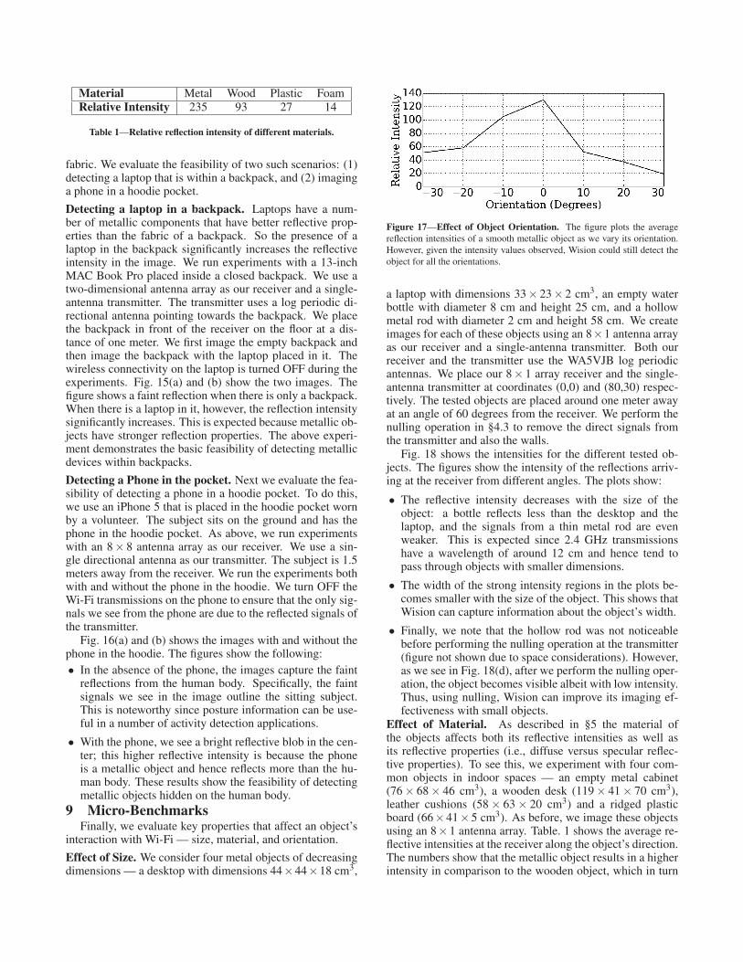
Figure 17—Effect of Object Orientation. The figure plots the average
reflection intensities of a smooth metallic object as we vary its orientation.
However, given the intensity values observed, Wision could still detect the
object for all the orientations.
a laptop with dimensions 33× 23× 2 cm3, an empty waterbottle with diameter 8 cm and height 25 cm, and a hollowmetal rod with diameter 2 cm and height 58 cm. We createimages for each of these objects using an 8×1 antenna arrayas our receiver and a single-antenna transmitter. Both ourreceiver and the transmitter use the WA5VJB log periodicantennas. We place our 8× 1 array receiver and the single-antenna transmitter at coordinates (0,0) and (80,30) respec-tively. The tested objects are placed around one meter awayat an angle of 60 degrees from the receiver. We perform thenulling operation in §4.3 to remove the direct signals fromthe transmitter and also the walls.
Fig. 18 shows the intensities for the different tested ob-jects. The figures show the intensity of the reflections arriv-ing at the receiver from different angles. The plots show:
• The reflective intensity decreases with the size of theobject: a bottle reflects less than the desktop and thelaptop, and the signals from a thin metal rod are evenweaker. This is expected since 2.4 GHz transmissionshave a wavelength of around 12 cm and hence tend topass through objects with smaller dimensions.
• The width of the strong intensity regions in the plots be-comes smaller with the size of the object. This shows thatWision can capture information about the object’s width.
• Finally, we note that the hollow rod was not noticeablebefore performing the nulling operation at the transmitter(figure not shown due to space considerations). However,as we see in Fig. 18(d), after we perform the nulling oper-ation, the object becomes visible albeit with low intensity.Thus, using nulling, Wision can improve its imaging ef-fectiveness with small objects.
Effect of Material. As described in §5 the material ofthe objects affects both its reflective intensities as well asits reflective properties (i.e., diffuse versus specular reflec-tive properties). To see this, we experiment with four com-mon objects in indoor spaces — an empty metal cabinet(76 × 68 × 46 cm3), a wooden desk (119 × 41 × 70 cm3),leather cushions (58 × 63 × 20 cm3) and a ridged plasticboard (66×41×5 cm3). As before, we image these objectsusing an 8×1 antenna array. Table. 1 shows the average re-flective intensities at the receiver along the object’s direction.The numbers show that the metallic object results in a higherintensity in comparison to the wooden object, which in turn

is a better reflector than the plastic object and the cushions(foam). This matches our intuition that an object’s materialaffects its reflectivity.
Effect of Orientation. Finally, the orientation of an objectaffects the intensity of the reflected signal, especially whenthe object acts like a mirror. So we pick the smooth metallicdesktop and compute the average intensity observed in thedirection of the object. We repeat the experiment for differ-ent object orientations. We again replicate the set up in theprevious experiment with a directional antenna at the trans-mitter and an 8×1 antenna array as the receiver.
Fig. 17 plots the average intensity values as a function ofthe smooth metallic object’s orientation. The figure showsthat the reflective intensity significantly varies with the ori-entation of the object. This is expected because smooth sur-faces have larger specular (mirror-like) reflections. The highintensity value in the figure corresponds to the orientationwhere the receiver lies along the direct reflected ray from theobject. We note that while the intensity values change, wecan still image the object for all the orientation values.
10 Limitations and DiscussionsFinally, we summarize the limits of Wi-Fi imaging; some
of these correspond to our specific implementation and oth-ers that are more fundamental.
Object Size and Material. Our evaluation demonstrates Wi-sion’s ability to image and localize either relatively large ob-jects such as couches, desktops, and T-shaped objects or ob-jects that have good reflective properties (e.g., metallic sur-faces). Smaller objects of the same material have smallercross-sections and reflect a smaller fraction of the incidentwireless signals; hence making them harder to image. Fur-ther, as the size of the object becomes proportional to thewavelength of Wi-Fi signals (approx. 12 cm at 2.4 GHz), itsinteraction with the Wi-Fi signals reduces. This is a funda-mental limitation of imaging with Wi-Fi transmissions. Onecould address this by going to higher frequencies (i.e., 5 GHzWi-Fi) that have a smaller wavelength (approx. 6 cm). Wehowever believe that Wision still represents a significant ca-pability that will be useful in many areas ranging from in-ventory tracking (e.g., tracking equipment such as trolleysand carts without having to tag them with sensors) to smarthomes (e.g., monitoring the status of large items like doors,windows, etc., without additional sensor deployment).
Imaging Resolution. As described in §5, the imaging resolu-tion with Wi-Fi signals depends on two main parameters: thesignal wavelength and the antenna array length. For a givenwavelength, one can increase the imaging resolution by in-creasing the length of the antenna array. We believe that theresolution we achieved is close to the optimal at 2.4 GHz forthe considered array lengths and is unlikely to increase with-out either increasing the length of the antenna array or using5 GHz Wi-Fi transmissions. We also note that the resolu-tion mainly depends on the length of the antenna array andnot on the number of antennas. Specifically, recent theoreti-cal work has shown that one can achieve similar resolutionswith lesser number of antennas as long as the length of theantenna array is kept constant [30].
Object Orientation. One of the key constraints we found
with our prototype implementation is that Wi-Fi transmis-sions in the environment reach an object only if that objectlies within the radiation pattern of the transmitter. Further,since smooth metallic surfaces act like mirrors, they couldbe oriented such that they are hidden from view for certaintransmitter positions. To address these issues, one may eitherpick antennas with better radiation patterns or optimize theantenna position to maximize their reach. Another approachis to leverage transmissions from multiple Wi-Fi devices inthe environment, which are naturally likely to be at differentpositions. Further, one can leverage the mobility of wirelessdevices (e.g., smartphones) to create images by stitching to-gether the intensities as the user moves around. Exploringthese approaches, however is not in the scope of this paper.
11 ConclusionWe present Wision, a novel imaging system that uses nar-
rowband wireless transmissions (e.g., Wi-Fi). Wision lever-ages multi-path propagation that results in wireless signalsbouncing off of objects before arriving at the receiver. Thesereflections effectively light up the objects, which Wision usesto image them. We also show how to extract depth informa-tion where objects that are at different distances from thereceiver can be identified. We implement a prototype of Wi-sion and image objects such as leather couches and metallicshapes in both line-of-sight and non-line-of-sight scenarios.We also demonstrate proof-of-concept applications includ-ing localization of static humans and objects using Wision,without the need for tagging them with RF devices. Finally,we explore the limits of our Wi-Fi based imaging approach.
Acknowledgements: We would like to thank the anony-mous SenSys reviewers for their helpful comments. Thisresearch is funded in part by the NSF award CNS-1420654,Google Faculty Award, and University of Washington.
12 References[1] Hg2415g grid antenna. http://www.l-com.com/multimedia/
datasheets/DS_HG2415G-NF-5PK.PDF.
[2] wa5vjb directional antenna. http://www.wa5vjb.com/pcb-pdfs/
LP8565.pdf.
[3] Xirrus corporation. http://www.xirrus.com.
[4] F. Ahmad and M. Amin. Through-the-wall human motion indicationusing sparsity-driven change detection. In IEEE Transactions on Geo-science and Remote Sensing, 2013.
[5] F. Ahmad, M. Amin, and P. Setlur. Through-the-wall target localiza-tion using dual-frequency cs radars. In Proc. SPIE 6201, C3I Tech-nologies for Homeland Security and Homeland Defense V, 62010H,2006.
[6] G. Airy. On the diffraction of an object-glass with circular aperture.In Transactions of the Cambridge Philosophical Society, 1835.
[7] I. Amundson, J. Sallai, X. Koutsoukos, and A. Ledeczi. Rf angleof arrival-based node localization. In International Journal of SensorNetworks, 2011.
[8] P. Bahl and V. N. Padmanabhan. Radar: An in-building rf-based userlocation and tracking system. In INFOCOM, 2000.
[9] P. Beckmann and A. Spizzichino. The scattering of electromagneticwaves from rough surfaces. Artech house, 1987.
[10] D. Bharadia, K. Joshi, and S. Katti. Full duplex backscatter. In Hot-nets, 2013.
[11] D. Bharadia, E. McMilin, and S. Katti. Full duplex radios. In Sig-comm, 2013.
[12] W. Carrara, R. Goodman, and R. Majewski. Spotlight Synthetic Aper-ture Radar: Signal Processing Algorithms. Artech House, 1995.

(a) Desktop (b) Laptop (c) Bottle (d) Rod
Figure 18—Effect of size. The plots show the intensity maps captured using a one-dimensional antenna array as the receiver. The plots show that the intensity
of the multi-path reflections decrease with the size of the object. Further, the width of the reflections is proportional to the width of the object. Wision however
could extract the intensity values for all the tested objects using its nulling algorithm.
[13] G. Charvat, L. Kempel, E. Rothwell, C. Coleman, and E. Mokole. AThrough-dielectric Radar Imaging System. In Trans. Antennas andPropagation, 2010.
[14] K. Chetty, G. Smith, and K. Woodbridge. Through-the-wall Sensingof Personnel Using Passive Bistatic WiFi Radar at Standoff Distances.In Trans. Geoscience and Remote Sensing, 2012.
[15] K. Chintalapudi, A. Iyer, and V. Padmanaban. Indoor Localizationwithout the Pain. In NSDI, 2011.
[16] J. R. Costa, E. B. Lima, C. R. Medeiros, T. Radil, R. C. Martins, P. M.Ramos, and C. A. Fernandes. Development of an Indoor Wireless Per-sonal Area Network based on Mechanically steered millimeter-wavelens antenna. In I2MTC, 2010.
[17] O. K. Ersoy. Diffraction, Fourier Optics and Imaging. John WileySons, 2006.
[18] F. FAdib, Z. adelec, D. Katabi, and R. Miller. 3d localization viahuman body reflections. In NSDI, 2014.
[19] F. FAdib and D. Katabi. Seeing Through Walls Using WiFi! In SIG-COMM, 2013.
[20] J. P. Fitch. Synthetic Aperture Radar. 1988.
[21] J. Friedman, Z. Charbiwala, T. Schmid, Y. cho, and M. Srivastava.Angle-of-arrival assisted radio interferometry target localization. InMILCOM, 2008.
[22] J. Gjengset, J. Xiong, G. McPhilips, and K. Jamieson. EnablingPhased Array Signal Processing on Commodity WiFi access points.In Mobicom, 2014.
[23] A. Gonzalez-Ruiz and Y. Mostofi. Cooperative robotic structure map-ping using wireless measurements, a comparison of random and coor-dinated sampling patterns. In IEEE Sensors Journal, 2013.
[24] A. Gonzelez-Ruiz, A. Ghaffarkhah, and Y. Mostofi. An integratedframework for obstacle mapping with see-through capabilities usinglaser and wireless channel measurements. In IEEE Sensors, 2014.
[25] D. Harperin, W. Hu, A. Sheth, and D. Wetherall. Gathering 802.11ntraces with channel state information. In CCR, 2011.
[26] E. Hecht. Optics, 2nd Edition. 1987.
[27] J. Hunt, T. Driscoll, A. Mrozack, G. Lipworth, M. Reynolds, D. Brady,and D. Smith”. Metamaterial apertures for computational imaging. InScience, 2013.
[28] B. Kellogg, V. Talla, and S. Gollakota. Bringing gesture recognitionto all devices. In NSDI, 2014.
[29] D. Y. Kim and O. Kenneth. 280ghz and 860ghz image sensors usingschottky-barrier diodes in 0.13m digital cmos. In International Solid-State Circuits Conference, 2012.
[30] J. Krieger, Y. Kochman, and G. Wornell. Multi-Coset, Sparse ImagingArrays. In IEEE transactions on Antennas and Propogation, 2014.
[31] C.-P. Lai and R. Narayanan. Through-wall imaging and characteriza-tion of human activity using ultrawideband (uwb) random noise radar.In C3I Technologies for Homeland Security and Homeland Defense,2005.
[32] N. Levanon and E. Mozeson. Radar Signals. John Wiley Sons, 2004.
[33] K. Lin, S. Gollakota, and D. Katabi. Random Access HeterogeneousMIMO Networks. In SIGCOMM, 2011.
[34] V. Lubecke, O. Boric-Lubecke, H. Madsen, and A. Fathy. Through-the-wall radar life detection and monitorin. In IEEE/MTT-S, 2007.
[35] P. Maechler, N. Felber, and H. Kaeslin. Compressive sensing for wifi-based passive bistatic radar. In EUSIPCO, 2012.
[36] Y. Mostofi. Cooperative wireless-based obstacle/object mapping andsee-through capabilities in robotic networks. In IEEE Transactions onMobile Computing, 2013.
[37] N. Patwari, L. Brewer, Q. Tate, O. Kaltiokallio, and M. Bocca.Breathfinding: A Wireless Network That Monitors and LocatesBreathing in a Home. In IEEE Journal Signal Processing, 2014.
[38] Q. Pu, S. Gupta, S. Gollakota, and S. Patel. Whole-Home GestureRecognition Using Wireless Signals. In MOBICOM, 2013.
[39] T. Ralston, G. Charvat, and J. Peabody. Real-time through-wall imag-ing using an ultrawideband MIMO phased array radar system. In Ar-ray, 2010.
[40] S. Ram and H. Ling. Through-wall tracking of human movers usingjoint doppler and array processing. In Geoscience and Remote Sens-ing, 2008.
[41] C. Rodenbeck and K. Chang. Automated pattern measurement forcircularly-polarized antennas using the phase-amplitude method. InMicrowave Journal, 2004.
[42] A. Saeed, A. E. Kosba, and M. Youssef. Ichnaea: A low-overheadrobust wlan device-ftree passive localization system. In IEEE Journalof selected topics in signal processing, 2014.
[43] R. O. Schmidt. Multiple Emitter Location and Signal Parameter Esti-mation. In IEEE Trans. on Antennas and Propagation, AP-34(3):276-280,Mar. 1986.
[44] S. Sen, B. Radunovic, R. R. Choudhury, and T. Minka. Spot localiza-tion using PHY layer information . In Mobisys, 2012.
[45] C. Shepard, H. Yu, N. Anand, E. Li, T. Marzetta, R. Yang, andL. Zhong. Argos: practical many-antenna base stations. In Mobicom,2012.
[46] S. Sigg, S. Shi, and Y. Ji. Rf-based device-free recognition of simul-taneously conducted activities. In Ubicomp, 2013.
[47] M. Skolnik. Radar Handbook. McGraw-Hill, 1988.
[48] H. Wang, S. Sen, A. Elgohary, M. Youssef, and R. R. Choudhury.No need to war-drive: unsupervised indoor localization. In MobiSys,2012.
[49] Y. Wang, M. Kuhn, and A. Fathy. Advanced system level simulationof uwb three-dimensional through-wall imaging radar for performancelimitation prediction. In MTT, 2010.
[50] J. Wilson and N. Patwari. Through-Wall Motion Tracking UsingVariance-Based Radio Tomography Networks. In ARXIV, 2009.
[51] J. Xiong and K. Jamieson. ArrayTrack: A Fine-Grained Indoor Loca-tion System. In NSDI, 2013.
[52] Q. Yang, X. Li, H. Yao, J. Fang, K. Tan, W. Hu, J. Zhang, andY. Zhang. BigStation: Enabling Scalable Real-time Signal Process-ing in Large MU-MIMO Systems. In SIGCOMM, 2013.
[53] M. Youssef and A. Agrawala. The horus wlan location determinationsystem. In MobiSys, 2005.
[54] Y. Zhao and N. Patwari. Robust Estimators for Variance-BasedDevice-Free Localization and Tracking. In ARXIV, 2011.
[55] F. Zhu, S. Gao, A. Ho, W. Brown, J. Li, and J. Xu. Low-profile di-rectional ultra-wideband antenna for see-through-wall imaging appli-cations. In Electromagnetics Research, 2011.