fea dos and dont
DESCRIPTION
Basic don't and dos for a stress analystTRANSCRIPT
Finite Element Modeling and AnalysisFinite Element Modeling and Analysis
Do’s and Don’tsDo’s and Don’ts
Hormoz Zareh, Associate professorHormoz Zareh, Associate professor
Mechanical Engineering Dept. Portland State UniversityMechanical Engineering Dept. Portland State University
SAE Meeting, October 24, 2003SAE Meeting, October 24, 2003
What is Finite Element Analysis or Modeling?What is Finite Element Analysis or Modeling?
Analysis:Analysis: A numerical method for approximation of a A numerical method for approximation of a complex differential equation problem (discrete or complex differential equation problem (discrete or continuous) into a finite number of solvable algebraic continuous) into a finite number of solvable algebraic equations.equations.
Modeling:Modeling: Subdividing a physical structure into a number Subdividing a physical structure into a number of small (of small (finitefinite) entities () entities (elementselements). This is followed by ). This is followed by application of prescribed boundary conditions (loads and application of prescribed boundary conditions (loads and restraints).restraints).
What is F.E. Analysis all about?What is F.E. Analysis all about?
Fundamental design question:
What type of analysis is needed, and how will the outcome be related to the design performance requirements?
Requirements to perform FEA/FEMRequirements to perform FEA/FEM
Grasp of the problem areaGrasp of the problem area Knowledge of the field (Structural, thermal, etc.)Knowledge of the field (Structural, thermal, etc.) Ability to solve a simplified version via analytical methodsAbility to solve a simplified version via analytical methods
Fundamental background in FE modeling and AnalysisFundamental background in FE modeling and Analysis Take formal training courses, not just vendor’s “how to” class.Take formal training courses, not just vendor’s “how to” class. Think about all the loading conditions that could affect the design, Think about all the loading conditions that could affect the design,
including thermal, mechanical, motion, etc. including thermal, mechanical, motion, etc. Simplify CAD models to the minimum required detail. Simplify CAD models to the minimum required detail. Start with a simple model, and add complexity later. Start with a simple model, and add complexity later. Double check the input data (material and physical properties). Double check the input data (material and physical properties). Examine the model with a range of boundary conditions instead of Examine the model with a range of boundary conditions instead of
just one. just one. Indicates design sensitivities!Indicates design sensitivities! Discuss the model and results with your colleagues.Discuss the model and results with your colleagues.
More about Fundamental requirementsMore about Fundamental requirements
Remember that FE modeling is more than preparing a mesh and preprocessing.
Skill in modeling is based on the visualization of physical behavior and relating it to the specific element behavior.
Acquire broad knowledge base.
Know and remember the assumptions and underlying Know and remember the assumptions and underlying restrictions of the analysis tools.restrictions of the analysis tools.
Always start simple and be prepared to revise your model.
Evaluate the results with a healthy dose of skepticism.
Structure behavior vs. Element behavior
The single most important underlying question in FE modeling and analysis:
“Which element should I use for a given problem?”
The answer is not simple.
Correct element identification, mesh density, and application of boundary conditions are all part of the following principle:
Thorough understanding of how the original design is likely to behave under the actual loads/boundary conditions, and how selected elements are able to simulate that behavior
Some general Modeling guidelines:
Include as much of the structure as possible in the model.
Do not omit part of the structure on the assumption that it does not influence the rest of the system by “being lightly stressed!”
Use finer mesh (than the one used to obtain displacements) to obtain stresses.
Use symmetry when appropriate, avoid when unsure about the outcome.
General Modeling guidelines:(Continued)
Keep the design detail at a level which can be easily managed for future analysis and verification.
Generate the beam models with curves and edges and not the actual cross sections.
Eliminate minor geometric details such as fillets, chamfers, tiny holes, etc. They complicate the FE mesh while not influencing the analysis outcome.
General Modeling guidelines:(Continued)
If some details are necessary, include them such that they can be easily identified and suppressed prior to FE modeling and analysis.
Take advantage of “partitioning” to divide complex shapes into a series of simpler geometries.
General Modeling guidelines:(Continued)
If the problem involves nonlinearity or anisotropy, analyze a linear isotropic version of the problem first.
When dynamic effects are present, perform a static analysis first, using loads that approximate the dynamic effect.
Do not use a symmetric half of the model for modal analysis (Natural frequencies and modes).
Sources of ErrorSources of Error and Concept of Error estimation and Concept of Error estimation
One must distinguish between inherent errors in the FE process and plain “mistakes.”
The mistakes include such things as entering the wrong data (such as material or properties, thickness of a member, forgetting the support or loads, etc.)
Modeling errors include using the wrong element formulation, modeling the incorrect geometry, using a poor mesh distribution, and numerical error (due to limitation of computing accuracy).
Sources of Error and Concept of Error estimationSources of Error and Concept of Error estimation(Continued)(Continued)
Another source of modeling error may arise when a load is distributed over a small region.
The solution at the immediate vicinity of the load requires considerable mesh refinement. However, if the desired area is a reasonably far away from the load location, coarse mesh could be sufficient.
Rule of thumb based on St. Venant’s principle:
The error is generally small when the distance (at which measurement is taken) is at least five times the width of the original distributed load.
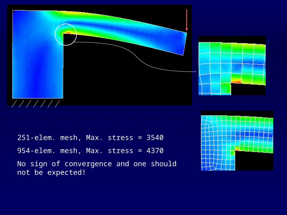
251-elem. mesh, Max. stress = 3540
954-elem. mesh, Max. stress = 4370
No sign of convergence and one should not be expected!
Element-by-element stress field
This type of stress distribution is discontinuous between elements, while stresses computed from nodal averaging are continuous.
One method of judging an approximate error field is to observe the difference between element-by-element and nodal averaging quantities.
Typically, the amount of discontinuity between elements is regarded as a measure of error.
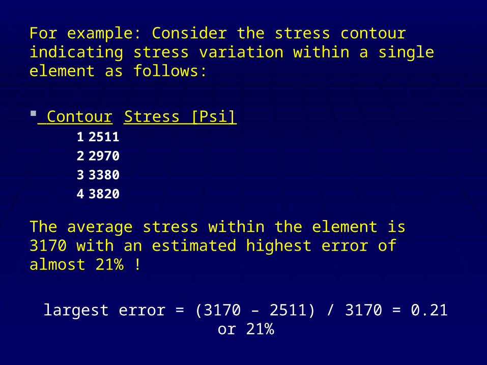
For example: Consider the stress contour indicating stress variation within a single element as follows:
Contour Stress [Psi]1 2511
2 2970
3 3380
4 3820
The average stress within the element is 3170 with an estimated highest error of almost 21% !
largest error = (3170 – 2511) / 3170 = 0.21 or 21%
Mesh refinementMesh refinement
This is based on the assumption that discontinuities in element-by-element stress field are indicative of error. However, physical discontinuities may exist which produce realistic, and often desirable, stress discontinuities.
Mesh should not be refined to the extent that the size of the smallest element is considerably smaller than the largest one.
Finally, adaptive meshing may give the analyst a false sense of security that by achieving convergence, a correct solution has been obtained.
Rule of thumb: Keep the ratio to below 100:1 (linear dimensions) or 1000:1 (area dimensions).
Element SelectionElement Selection
Forms the foundation of FE modeling and analysis.Forms the foundation of FE modeling and analysis.
Example: 4-node QUADS are preferred to 3-node triangular Example: 4-node QUADS are preferred to 3-node triangular elements.elements.
Linear formulations with successive refinements yield good Linear formulations with successive refinements yield good results.results.
Avoid higher order elements unless necessary, or in critical Avoid higher order elements unless necessary, or in critical situations (medical device, aerospace).situations (medical device, aerospace).
ElementsElements
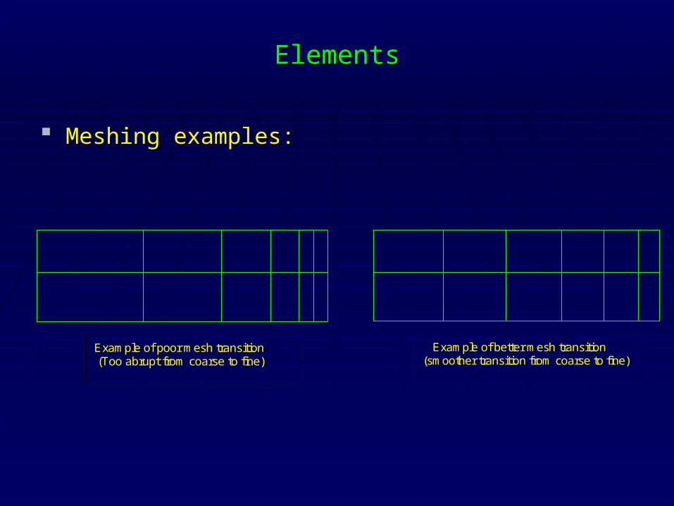
Meshing examples:Meshing examples:
Example of poor mesh transition (Too abrupt from coarse to fine)
Example of better mesh transition(smoother transition from coarse to fine)
ElementsElements (continued)(continued)
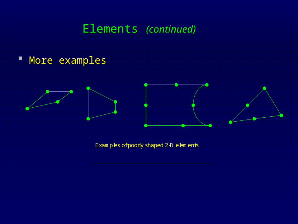
More examplesMore examples
Examples of poorly shaped 2-D elements
ElementsElements (continued)(continued)
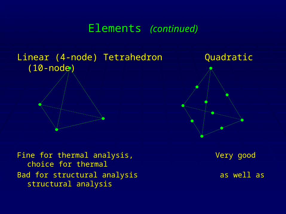
Linear (4-node) TetrahedronLinear (4-node) Tetrahedron Quadratic (10-node) Quadratic (10-node)
Fine for thermal analysis, Fine for thermal analysis, Very good choice for thermal Very good choice for thermal
Bad for structural analysisBad for structural analysis as well as structural analysis as well as structural analysis
Physical and Material propertiesPhysical and Material properties
Make sure proper material and physical properties are Make sure proper material and physical properties are used in the analysis.used in the analysis.
A common mistake is to inadvertently use the software’s A common mistake is to inadvertently use the software’s defaults for the analysis.defaults for the analysis.
Some default properties used in certain FEA program:Some default properties used in certain FEA program:Thickness of Shell elements = 0.038 in. (1 mm)Thickness of Shell elements = 0.038 in. (1 mm)
Material property = Generic Isotropic SteelMaterial property = Generic Isotropic Steel
Boundary ConditionsBoundary Conditions
A critical aspect of the modeling is the proper A critical aspect of the modeling is the proper transformation of the actual boundary conditions to the transformation of the actual boundary conditions to the loads/restraints set of the FE software. For example, loads/restraints set of the FE software. For example, Dynamic (Modal) analysis is very sensitive to the boundary Dynamic (Modal) analysis is very sensitive to the boundary conditions.conditions.
A model must be “fully restrained” for proper analysis. A model must be “fully restrained” for proper analysis. Otherwise, Otherwise, RIGID BODYRIGID BODY modes will cause solution failure modes will cause solution failure (in Static analysis), or unexpected vibration modes (in (in Static analysis), or unexpected vibration modes (in Dynamic analysis).Dynamic analysis).
Boundary Conditions Boundary Conditions (continued)(continued)
For models which are not fully restrained:For models which are not fully restrained:
Static analysis:Static analysis: completely restrain one node. Pick a node completely restrain one node. Pick a node which is not close to the area of deflection/stress which is which is not close to the area of deflection/stress which is being investigated.being investigated.
Dynamic analysis:Dynamic analysis: set the first natural frequency to a small set the first natural frequency to a small number greater than zero, yet small enough to not interfere number greater than zero, yet small enough to not interfere with the actual frequency.with the actual frequency.
Thermal analysis:Thermal analysis: restraints are applied as temperature. restraints are applied as temperature. Condition of symmetry is imposed as insulation!Condition of symmetry is imposed as insulation!
Solution strategySolution strategy
Decide on a solution strategy which best meets the design Decide on a solution strategy which best meets the design requirements. requirements.
Static analysis vs. Dynamic analysisStatic analysis vs. Dynamic analysis
Modal analysis vs. Shock (impact) loadingModal analysis vs. Shock (impact) loading
Structural vs. Thermal (or combined) analysisStructural vs. Thermal (or combined) analysis
First few modes represent displacements quite well, but First few modes represent displacements quite well, but impact loading cannot be modeled correctly with Modal impact loading cannot be modeled correctly with Modal analysis solution!analysis solution!
Post processing Post processing
View the results with critical eyes. View the results with critical eyes.
Don’t be impressed by color contours, and what might Don’t be impressed by color contours, and what might “seem” to be a convincing output.“seem” to be a convincing output.
Common sense and good engineering judgment are far Common sense and good engineering judgment are far more important than the computer output.more important than the computer output.
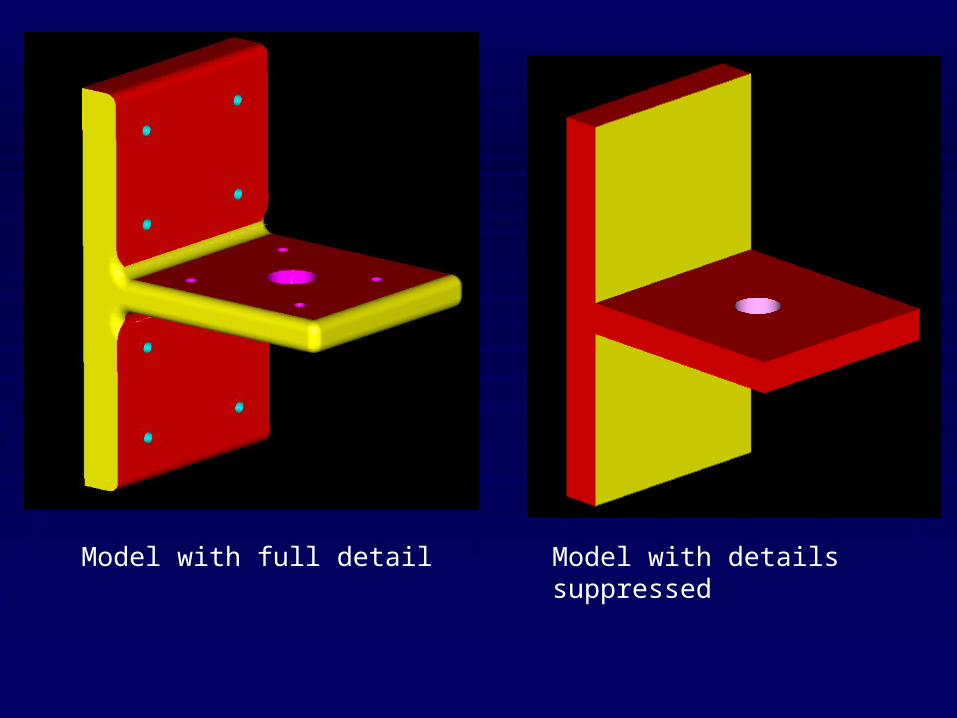
Model with full detail Model with details suppressed
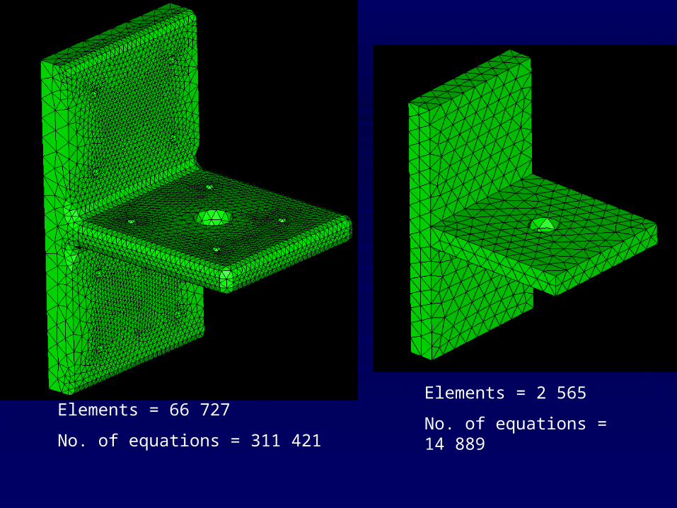
Elements = 2 565
No. of equations = 14 889Elements = 66 727
No. of equations = 311 421
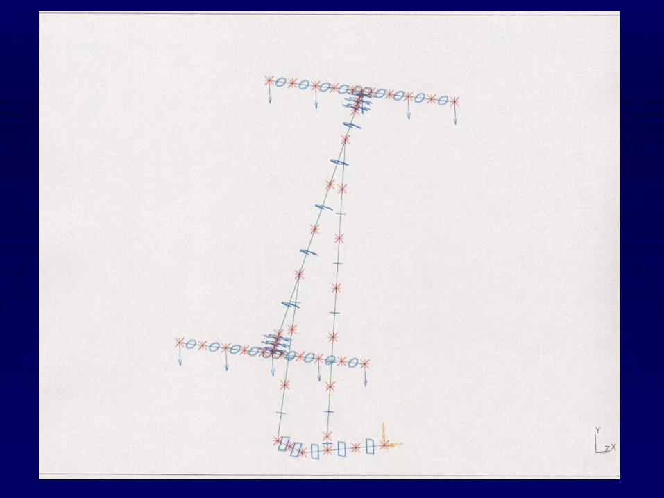
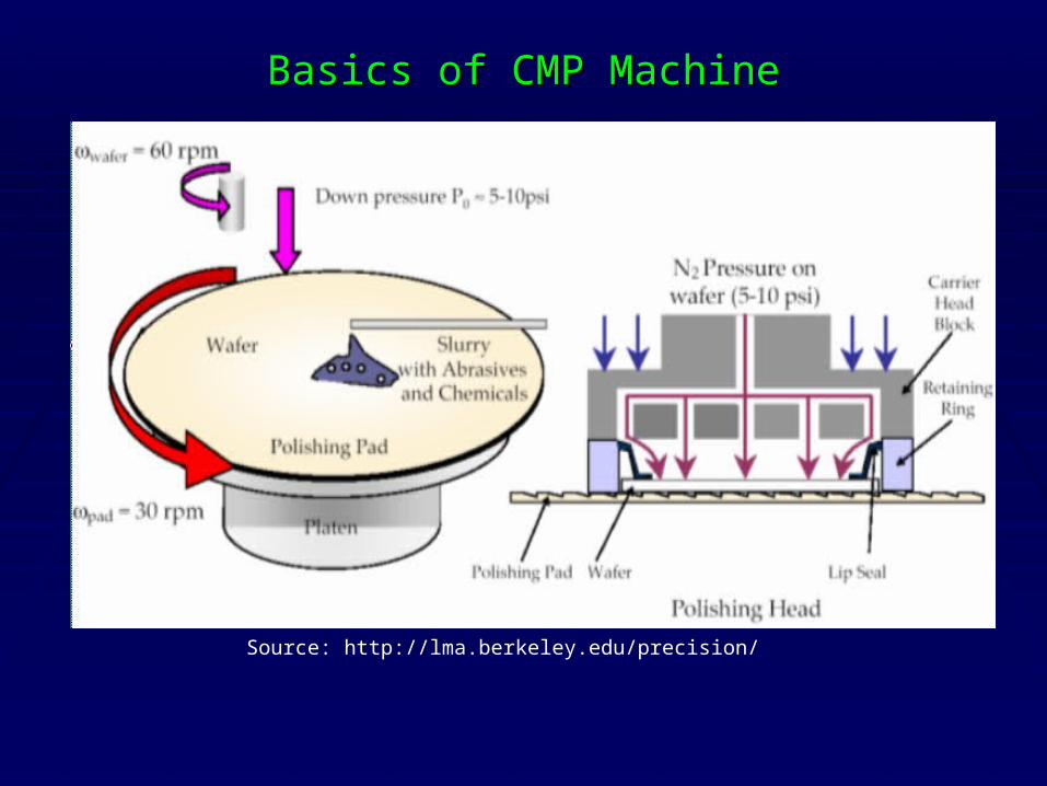
Basics of CMP MachineBasics of CMP Machine
Source: http://lma.berkeley.edu/precision/
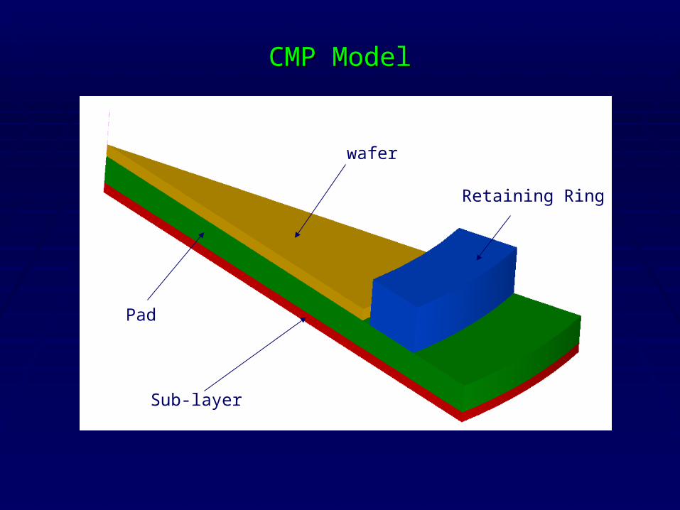
CMP ModelCMP Model
wafer
Sub-layer
Pad
Retaining Ring
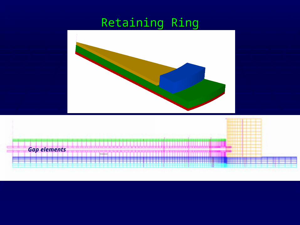
Retaining RingRetaining Ring
Gap elements
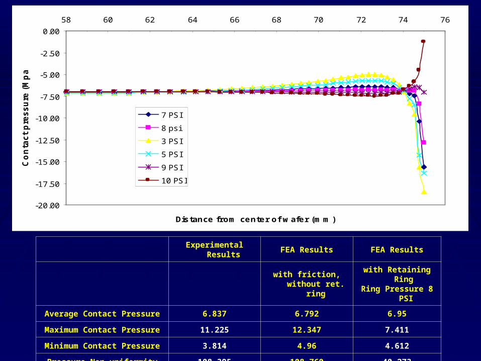
-20.00
-17.50
-15.00
-12.50
-10.00
-7.50
-5.00
-2.50
0.00
58 60 62 64 66 68 70 72 74 76
Distance from center of w afer (m m )
Co
nta
ct
pre
ss
ure
(M
pa
)
7 PSI
8 psi
3 PSI
5 PSI
9 PSI
10 PSI
Experimental Results FEA Results FEA Results
with friction, without
ret. ringwith Retaining Ring Ring Pressure 8 PSI
Average Contact Pressure 6.837 6.792 6.95
Maximum Contact Pressure 11.225 12.347 7.411
Minimum Contact Pressure 3.814 4.96 4.612
Pressure Non-uniformity 108.395 108.760 40.273
Final ThoughtFinal Thought
“ Finite Element Analysis makes a good engineer great, and a bad engineer dangerous !”
Robert D. Cook, Professor of Mechanical EngineeringUniversity of Wisconsin, Madison