fdot modifications to standard specifications for
TRANSCRIPT
FLORIDA DEPARTMENT OF TRANSPORTATION
FDOT MODIFICATIONS TO STANDARD SPECIFICATIONS FOR STRUCTURAL SUPPORTS
FOR HIGHWAY SIGNS, LUMINAIRESAND TRAFFIC SIGNALS (LTS-6)
FDOT STRUCTURES MANUALVOLUME 3
JANUARY 2014

FDOT Modifications to LTS-6 Topic No. 625-020-018
January 2014
Table of Contents
Table of Contents . . . . . . . . . . . . . . . . . . . . . . . . . . . . . . . . . . . . . . . . . . . . . . . . . i1 Introduction. . . . . . . . . . . . . . . . . . . . . . . . . . . . . . . . . . . . . . . . . . . . . . . . . . . . . 1
1.1 Scope . . . . . . . . . . . . . . . . . . . . . . . . . . . . . . . . . . . . . . . . . . . . . . . . . . . . . . . 12 General Features of Design . . . . . . . . . . . . . . . . . . . . . . . . . . . . . . . . . . . . . . . . 1
2.1 Scope . . . . . . . . . . . . . . . . . . . . . . . . . . . . . . . . . . . . . . . . . . . . . . . . . . . . . . . 12.4 Functional Requirements . . . . . . . . . . . . . . . . . . . . . . . . . . . . . . . . . . . . . . . . 1
2.4.2 Structural Supports for Signs and Traffic Signals . . . . . . . . . . . . . . . . . . . 12.4.2.2 Size, Height and Location of Signs (Rev. 01/14) . . . . . . . . . . . . . . . . . 1Figure 1 Example: actual signs . . . . . . . . . . . . . . . . . . . . . . . . . . . . . . . . . . . . 2Figure 2 Example: signs used in design . . . . . . . . . . . . . . . . . . . . . . . . . . . . . 2
2.4.2.4 Variable Message Signs . . . . . . . . . . . . . . . . . . . . . . . . . . . . . . . . . . . . 32.4.2.5 Horizontal Span and Cantilever Limits (Rev. 01/14) . . . . . . . . . . . . . . . 3
3 Loads . . . . . . . . . . . . . . . . . . . . . . . . . . . . . . . . . . . . . . . . . . . . . . . . . . . . . . . . . . 33.8 Wind Load (Rev. 01/14) . . . . . . . . . . . . . . . . . . . . . . . . . . . . . . . . . . . . . . . . . 3
3.8.2 Basic Wind Speed . . . . . . . . . . . . . . . . . . . . . . . . . . . . . . . . . . . . . . . . . . . 33.8.3 Wind Importance Factor Ir . . . . . . . . . . . . . . . . . . . . . . . . . . . . . . . . . . . . . 4
FDOT Table 3-3 Minimum Design Life . . . . . . . . . . . . . . . . . . . . . . . . . . . . . . 43.8.6 Drag Coefficients Cd . . . . . . . . . . . . . . . . . . . . . . . . . . . . . . . . . . . . . . . . . 43.8.7 Lift Coefficient for Traffic Signals Cl . . . . . . . . . . . . . . . . . . . . . . . . . . . . . 5
3.9 Design Wind Loads On Structures . . . . . . . . . . . . . . . . . . . . . . . . . . . . . . . . . 53.9.1 Load Application . . . . . . . . . . . . . . . . . . . . . . . . . . . . . . . . . . . . . . . . . . . . 53.9.3 Design Loads for Vertical Supports . . . . . . . . . . . . . . . . . . . . . . . . . . . . . . 5
3.10 References . . . . . . . . . . . . . . . . . . . . . . . . . . . . . . . . . . . . . . . . . . . . . . . . . . 65 Steel Design . . . . . . . . . . . . . . . . . . . . . . . . . . . . . . . . . . . . . . . . . . . . . . . . . . . . 6
5.5 Material - Structural Steel . . . . . . . . . . . . . . . . . . . . . . . . . . . . . . . . . . . . . . . . 65.13 Cables And Connections. . . . . . . . . . . . . . . . . . . . . . . . . . . . . . . . . . . . . . . . 65.14 Details of Design . . . . . . . . . . . . . . . . . . . . . . . . . . . . . . . . . . . . . . . . . . . . . . 6
5.14.3 Transverse Plate Thickness (Rev. 01/14) . . . . . . . . . . . . . . . . . . . . . . . . 65.15 Welded Connections . . . . . . . . . . . . . . . . . . . . . . . . . . . . . . . . . . . . . . . . . . . 6
5.15.1 Tube-to-Tube Splice Circumferential Welds . . . . . . . . . . . . . . . . . . . . . . 75.15.3 Tube-to-Transverse Plate Connection Welds . . . . . . . . . . . . . . . . . . . . . 7
5.16 Bolted Connections . . . . . . . . . . . . . . . . . . . . . . . . . . . . . . . . . . . . . . . . . . . . 75.17 Anchor Bolt Connections. . . . . . . . . . . . . . . . . . . . . . . . . . . . . . . . . . . . . . . . 7
5.17.1 Anchor Bolt Types . . . . . . . . . . . . . . . . . . . . . . . . . . . . . . . . . . . . . . . . . . 85.17.2 Anchor Bolt Materials . . . . . . . . . . . . . . . . . . . . . . . . . . . . . . . . . . . . . . . 85.17.2.4 Anchor Bolt Holes in Base Plate (Rev. 01/14) . . . . . . . . . . . . . . . . . . 8
5.17.3 Design Basis . . . . . . . . . . . . . . . . . . . . . . . . . . . . . . . . . . . . . . . . . . . . . . 85.17.3.1 Double-Nut Anchor Bolt Connections (Rev. 01/14). . . . . . . . . . . . . . . 85.17.3.3 Use of Grout (Rev. 01/14) . . . . . . . . . . . . . . . . . . . . . . . . . . . . . . . . . . 9
iStructures Manual Home

FDOT Modifications to LTS-6 Topic No. 625-020-018
January 2014
5.17.4 Anchor Bolt Design . . . . . . . . . . . . . . . . . . . . . . . . . . . . . . . . . . . . . . . . . 95.17.4.3 Bending Stress in Anchor Bolts (Rev. 01/14) . . . . . . . . . . . . . . . . . . . 9
5.19 References (Rev. 01/14) . . . . . . . . . . . . . . . . . . . . . . . . . . . . . . . . . . . . . . . . 96 Aluminum Design . . . . . . . . . . . . . . . . . . . . . . . . . . . . . . . . . . . . . . . . . . . . . . . . 10
6.1 Scope . . . . . . . . . . . . . . . . . . . . . . . . . . . . . . . . . . . . . . . . . . . . . . . . . . . . . . . 107 Prestressed Concrete Design . . . . . . . . . . . . . . . . . . . . . . . . . . . . . . . . . . . . . . 10
7.5 Design . . . . . . . . . . . . . . . . . . . . . . . . . . . . . . . . . . . . . . . . . . . . . . . . . . . . . . . 107.5.1 Method of Design . . . . . . . . . . . . . . . . . . . . . . . . . . . . . . . . . . . . . . . . . . . 107.5.2 Concrete Strength . . . . . . . . . . . . . . . . . . . . . . . . . . . . . . . . . . . . . . . . . . . 10
7.10 Durability . . . . . . . . . . . . . . . . . . . . . . . . . . . . . . . . . . . . . . . . . . . . . . . . . . . . 107.10.2 Concrete Cover . . . . . . . . . . . . . . . . . . . . . . . . . . . . . . . . . . . . . . . . . . . . 10
10 Serviceability Requirements . . . . . . . . . . . . . . . . . . . . . . . . . . . . . . . . . . . . . . 1110.5 Camber . . . . . . . . . . . . . . . . . . . . . . . . . . . . . . . . . . . . . . . . . . . . . . . . . . . . . 11
11 Fatigue Design . . . . . . . . . . . . . . . . . . . . . . . . . . . . . . . . . . . . . . . . . . . . . . . . . 1111.6 Fatigue Importance Factors (Rev. 01/14) . . . . . . . . . . . . . . . . . . . . . . . . . . . 1111.7 Fatigue Design Loads . . . . . . . . . . . . . . . . . . . . . . . . . . . . . . . . . . . . . . . . . . 12
11.7.1 Galloping . . . . . . . . . . . . . . . . . . . . . . . . . . . . . . . . . . . . . . . . . . . . . . . . . 1211.8 Deflection . . . . . . . . . . . . . . . . . . . . . . . . . . . . . . . . . . . . . . . . . . . . . . . . . . . 12
13 Foundation Design . . . . . . . . . . . . . . . . . . . . . . . . . . . . . . . . . . . . . . . . . . . . . . 1213.6 Drilled Shafts. . . . . . . . . . . . . . . . . . . . . . . . . . . . . . . . . . . . . . . . . . . . . . . . . 12
13.6.1 Geotechnical Design . . . . . . . . . . . . . . . . . . . . . . . . . . . . . . . . . . . . . . . . 1313.6.1.1 Embedment (Rev. 01/14) . . . . . . . . . . . . . . . . . . . . . . . . . . . . . . . . . . 13
13.6.2 Structural Design . . . . . . . . . . . . . . . . . . . . . . . . . . . . . . . . . . . . . . . . . . . 1413.6.2.1 Details . . . . . . . . . . . . . . . . . . . . . . . . . . . . . . . . . . . . . . . . . . . . . . . . . 14
13.10 Embedment of Lightly Loaded Small Poles and Posts . . . . . . . . . . . . . . . . 1413.11 References . . . . . . . . . . . . . . . . . . . . . . . . . . . . . . . . . . . . . . . . . . . . . . . . . 15
Appendix C . . . . . . . . . . . . . . . . . . . . . . . . . . . . . . . . . . . . . . . . . . . . . . . . . . . . . . 151 Alternate Method (Rev. 01/14) . . . . . . . . . . . . . . . . . . . . . . . . . . . . . . . . . . . . . . 152 Wind Load . . . . . . . . . . . . . . . . . . . . . . . . . . . . . . . . . . . . . . . . . . . . . . . . . . . . . 16
FDOT Table C.2-1 Wind Speed by County . . . . . . . . . . . . . . . . . . . . . . . . . . . 17 Volume 3 - Revision History . . . . . . . . . . . . . . . . . . . . . . . . . . . . . . . . . . . . . . . . R3-1
iiStructures Manual Home

FDOT Modifications to LTS-6 Topic No. 625-020-018
January 2014
1 INTRODUCTION
C 1.1Add the following:Structures Manual Introduction I.6 is updated annually to reflect the specific specifications editions and interims adopted by the FDOT.
1.1 Scope
Add the following:
Conform to the date specific AASHTO Publications listed in Structures Manual Introduction I.6 References.
2 GENERAL FEATURES OF DESIGN
C 2.1Add the following:The FDOT Plans Preparation Manual contains additional FDOT requirements for sign, signal and lighting structures. The FDOT Design Standards contains drawings for all typical sign, signal and lighting structures.
2.1 Scope
Add the following:
See Chapters 2, 7 and 29 of the FDOT Plans Preparation Manual, Volume 1 regarding the use of FDOT Design Standards and other plans preparation requirements.
2.4 Functional Requirements
2.4.2 Structural Supports for Signs and Traffic Signals
C 2.4.2.2Add the following:Minimum sign areas provide a reasonable allowance for future sign panel installations without the need for a new support structure.Minimum sign areas for overhead variable message sign supports are normally not required.See the FDOT PPM, Volume 1, Introduction for a link to the Urban Area Boundary Maps. See PPM, Volume 1 for cantilever and span overhead sign support location criteria.
2.4.2.2 Size, Height and Location of Signs (Rev. 01/14)
Add the following:
Span type overhead sign structures in urban locations shall be designed either for the actual signs shown on the signing plans or for a minimum sign area of 120 sq. ft. (12 ft. W x 10 ft. H) per lane, whichever is the greater. The minimum sign area applies to lanes without signs and lanes with sign sizes smaller than the minimum. If the signing plans require signs for only one traffic direction, the minimum sign area per lane requirement applies to the traffic lanes in this direction only.
Cantilever type overhead sign structures in urban locations shall be designed either for the actual signs shown on the signing plans or for a minimum sign area of 80 sq.
1Structures Manual Home

FDOT Modifications to LTS-6 Topic No. 625-020-018
January 2014
ft. (8 ft. W x 10 ft. H) located at the end of the cantilever, whichever provides the more stringent load or stress at the location under consideration.
Figures 1 and 2 show how to apply the above minimum sign areas for span type overhead sign structures in urban locations.
Overhead signs in rural locations should be designed for the actual sign shown on the signing plans.
Figure 1 Example: actual signs
Figure 2 Example: signs used in design
2Structures Manual Home

FDOT Modifications to LTS-6 Topic No. 625-020-018
January 2014
C 2.4.2.4Add the following:The minimum requirements given provide additional measures to limit the possibility of galloping.
Since cantilever overhead Variable Message Sign (VMS) structures are more susceptible to fatigue than span overhead VMS structures, span structures should be used whenever possible.
In Florida, overhead VMS structures are typically referred to as Dynamic Message Sign (DMS) structures.
2.4.2.4 Variable Message Signs
Add the following:
For all overhead Variable Message Sign (VMS) structures, the horizontal member shall consist of a truss with a minimum of two chords with a minimum center-to-center distance between the chords of 3'- 0". See FDOT section 11.8 for VMS maximum span-to-depth ratios.
FDOT vertical clearance requirements for VMS structures are found in PPM, Volume 1, Chapter 2.
C 2.4.2.5Add the following:These limits were chosen based on past practice and practical experience.A FDOT Design Variation is required when sign or signal structure limits are exceeded. The design variation documentation shall include the type of structure, height, length, discussion of alternatives, and costs.
2.4.2.5 Horizontal Span and Cantilever Limits (Rev. 01/14)
New Section, add the following:
Sign and signal structures shall be limited to the following maximum horizontal lengths:
Structure Type Max Length
Span Overhead Sign 220 feet
Cantilever Overhead Sign 50 feet
Mast Arm 78 feet
Span Wire Assembly 250 feet
3 LOADS
C 3.8For existing supports, FDOT PPM, Volume 1, Section 25.4.26 defines when structural evaluation is necessary and lists FDOT Design Exception and Variation requirements.
3.8 Wind Load (Rev. 01/14)
Delete the last paragraph and add the following:
The use of Appendix C is only permitted for the evaluation of existing structures.
C 3.8.2Add the following:FDOT SDG Table 2.4.1-2 was derived from the ASCE 7-05 wind speed map.To simplify the design process, FDOT has designated one wind speed per county.
3.8.2 Basic Wind Speed
Delete the entire paragraph including Figure 3-2, and add the following:
The wind loads shall be based on the wind speeds (mph) shown in FDOT SDG Table 2.4.1-2
3Structures Manual Home

FDOT Modifications to LTS-6 Topic No. 625-020-018
January 2014
C 3.8.3Add the following:A 1.5-year design life has been added for temporary construction signs. The importance factor is calculated based on "Wind Speed for Design of Temporary Structures" by D.W. Boggs and J.A. Peterka, Structures Congress, 1992, Compact Papers, ASCE, 1992.Florida has traditionally designed Luminaire support structures, 50 feet in height and less, and strain poles for a 25 year design life.Concrete strain poles are designed for zero tension stress, therefore a twenty-five year design life is appropriate.
3.8.3 Wind Importance Factor IrAdd the following Wind Importance Factor
to Table 3-2:
Recurrence Interval Years
V =85-100 mph
V > 100 mph
Alaska
1.5 0.45 0.2 ---
Delete Table 3-3 and add the following FDOT Table 3-3:
FDOT Table 3-3 Minimum Design Life
Design Life Structure Type
50-year
Overhead sign structuresLuminaire support structures >50' in height.Mast ArmsMonotubesSteel Strain PolesITS Camera Poles >50’ in height
25-yearLuminaire supports and other structures ≤ 50' in height.Concrete Strain Poles
10-year Roadside sign structures1.5-year Temporary construction signs
A 1.5-year design life (Ir = 0.2) for temporary construction signs shall only be used with a 150 mph design wind speed.
C 3.8.6Add the following to note 2 at the bottom of Table 3-6:A drag coefficient for traffic signal installed with the ability to swing has been established through research (Cook 2007). On span wire systems where signal and signs are allowed to swing, varying Cd as a function of swing angle is allowed (Hoit and Cook 1997).
3.8.6 Drag Coefficients Cd
Replace the coefficient of drag for Traffic Signals in Table 3-6 with the following:
Traffic Signals - no ability to swing - 1.2
Traffic Signals - installed with the ability to swing on span wire systems under full wind load - 0.7
4Structures Manual Home

FDOT Modifications to LTS-6 Topic No. 625-020-018
January 2014
C 3.8.7Add the following: A lift coefficient of 0.4 on traffic signals installed on span wire systems has been established through research (Cook 2007). On span wire systems where signal and signs are allowed to swing, varying Cl as a function of swing angle is allowed (Hoit and Cook 1997).
3.8.7 Lift Coefficient for TrafficSignals Cl
New Section, add the following:
For traffic signals installed with the ability to swing on span wire systems under full design wind speed (Group II loading), use a coefficient of lift Cl equal to 0.4. To compute the lift pressure, use Eq. 3-1 substituting Cl for Cd. Using a reduced signal area based on the swing angle, compute the lift force and apply in a vertical direction opposite dead load.
3.9 Design Wind Loads On Structures
C 3.9.1Add the following:Swing angles for traffic signals and signs installed on span wire systems have been established through research (Cook 2007).Areas given are for standard signals in Florida.
3.9.1 Load Application
Add the following:
Use the following areas for traffic signals:
Item Projected Area
12" Signal 1.36 sf8" Signal 0.70 sf3 Section Backplate 5.67 sf4 Section Backplate 6.83 sf5 Section Backplate 8.00 sf
When the full design wind speed is used for Group II loading on span wire systems, use a reduced signal and sign area based on the following swing angles:
Wind Speed Swing Angle
110 mph 45 degrees130 mph 55 degrees150 mph 60 degrees
C 3.9.3Add the following:More refined analysis is typically not required due to the number of approximate assumptions made in the analysis. Other angles may be analyzed and substituted if program results are not consistent at the specified angles.
3.9.3 Design Loads for Vertical Supports
Add the following:
When 3 or 4 span wire pole structures are connected, analyze the system with wind directions of 0, 45, and 90 degrees. If other angles are used, document the angles in the analysis report.
5Structures Manual Home

FDOT Modifications to LTS-6 Topic No. 625-020-018
January 2014
3.10 References
Add the following:
Cook, R.A. (2007). Development of Hurricane Resistant Cable Supported Traffic Signals (FDOT Report# BD545 RPWO #57). Gainesville, Florida: University of Florida.
Hoit, M.I., Cook, R.A. (1997). Computer Aided Design Program for Signal Pole and Span Wire Assemblies With Two Point Connection System (FDOT Report# 0510653). Gainesville, Florida: University of Florida.
5 STEEL DESIGN
C 5.4Add the following:In some environmental conditions in Florida, A588 steel has deteriorated significantly faster than expected.
5.5 Material - Structural Steel
Add the following:
Do not specify ASTM A588 (rustic, Corten, “self-oxidizing", or "self-weathering") steel in sign, signal, or lighting structures.
C 5.13Add the followingCables used in the construction of span-wire pole structures are listed in FDOT Specification 634.
5.13 Cables And Connections
Add the following:
Use the cable breaking strength values specified in FDOT Specification 634.
5.14 Details of Design
C 5.14.3Add the following:Research has proven full-penetration groove welds combined with thicker base plates increases the pole-to-base-plate connection fatigue strength.
5.14.3 Transverse Plate Thickness(Rev. 01/14)
Add the following:
The minimum base plate thickness shall be 2½ inches for mast arm signal structures and steel strain poles, and 3 inches for high mast light poles.
C 5.15Add the following:Section 5.15 is referenced as a requirement in FDOT Specification 460-6.4.
5.15 Welded Connections
6Structures Manual Home

FDOT Modifications to LTS-6 Topic No. 625-020-018
January 2014
C 5.15.1Add the following:The Department’s intent is to avoid any unnecessary welds on sign, signal or lighting structures.
5.15.1 Tube-to-Tube Splice Circumferential Welds
Add the following:
On steel sign and signal structures, no circumferential welds are permitted on the uprights, arms or chords with the exceptions of the base plate weld, the flange plate connections on tubular truss members, mitered arm-to-upright angle weld on monotubes and uprights greater than 40 feet in height.
C 5.15.3Add the following:Research has proven full-penetration groove welds combined with thicker base plates increases the pole-to-base-plate connection fatigue strength.
5.15.3 Tube-to-Transverse Plate Connection Welds
Add the following:
For base plate connections without stiffeners on 50 year recurrence interval structures, only use full-penetration groove welds.
C 5.16Add the following:Through bolted connections provide fully tensioned A325 bolts.
5.16 Bolted Connections
Add the following:
Design all pole to arm connections on Mast Arm structures as "through bolted". Tapped connections are not permitted. Do not use hardened steel washers between the end plate of a Mast Arm and the mounting plate of the pole.
C 5.17Add the following:A minimum of eight anchor bolts provides redundancy and better distribution of forces through the base plate.
5.17 Anchor Bolt Connections
Add the following:
All sign, signal, and lighting structures designed for a minimum service life of 50 years (wind speed based on a 50-year mean recurrence interval) shall use a minimum of eight, Grade 55, ASTM F1554 anchor bolts at the pole to foundation connection, with the exception of Mast Arm signal structures where the minimum is six anchor bolts.
7Structures Manual Home

FDOT Modifications to LTS-6 Topic No. 625-020-018
January 2014
C 5.17.1Add the following:FDOT only allows straight headed anchor bolts.Adhesive anchor and threaded post-tensioning bars have undesirable creep and non-ductile behavior respectively.
5.17.1 Anchor Bolt Types
Delete anchor bolts types listed in the second and third bullet and add the following:
Both Adhesive anchors and threaded post-tensioning bars are not permitted.
C 5.17.2Add the following:ASTM F 1554 Grade 55 anchor bolts provide sufficient ductility after yield to engage all the anchor bolts on the tension side of the base plate.
5.17.2 Anchor Bolt Materials
Add the following:
Only use ASTM F 1554 anchor bolts with 55 ksi yield strength.
C 5.17.2.4Oversized anchor bolt holes are allowed in Florida.
5.17.2.4 Anchor Bolt Holes in Base Plate (Rev. 01/14)
Delete the first bullet in the first paragraph.
5.17.3 Design Basis
C 5.17.3.1Add the following:A structural grout pad significantly contributes to the design load carrying capacity of anchor bolts in cantilever structures.
5.17.3.1 Double-Nut Anchor Bolt Connections (Rev. 01/14)
Add the following:
Use double-nut moment joints in all mast arm signal structures, steel strain poles, high mast light poles and overhead sign structures.
Replace the 2nd paragraph with the following:
In cantilever support structures, bending of the anchor bolt from shear and torsion shall be considered according to Article 5.17.4.3 unless a structural grout pad is provided. In non-cantilevered support structures, if the clear distance between the bottom of the bottom leveling nut and the top of concrete is less than the nominal anchor bolt diameter, bending of the anchor bolt from shear and torsion may be ignored. If the clear distance exceeds one bolt diameter, bending in the anchor bolt shall be considered according to Article 5.17.4.3.
8Structures Manual Home

FDOT Modifications to LTS-6 Topic No. 625-020-018
January 2014
C 5.17.3.3Add the following:When significant torsion is transmitted from the base plate to the anchor bolt group, a structural grout pad permits the anchors to develop their full shear strength, Cook et al. (2013).Inspections have shown that a poorly functioning grout pad is worse than no grout pad at all. For poles without a grout pad beneath the base plate, the double-nut moment joint requires adequate tensioning of the anchor bolts. It is critical that the nuts beneath the base plate, typically referred to as leveling nuts, are firmly tightened and locked to prevent loosening. This locking mechanism is accomplished through the turn of the nut method specified in FDOT Specification 649 or a properly placed grout pad.
5.17.3.3 Use of Grout (Rev. 01/14)
Add the following:
A structural grout pad is required under the base plates in double-nut moment joints of mast arm signal structures and cantilever overhead sign structures.
Grout pads are not required under the base plates in double-nut moment joints of span overhead sign structures, high mast light poles, steel strain poles and monotube structures.
5.17.4 Anchor Bolt Design
C 5.17.4.3Replace the first paragraph with the following:Bending stresses in individual bolts can be ignored in the following cases:● in non-cantilevered support structures,
if the standoff distance between the topof the foundation and bottom of theleveling nut is less than one boltdiameter.
● in cantilevered support structures, ifa structural grout pad is provided.
For larger standoff distances, the following beam model should be used. (See LTS.)
5.17.4.3 Bending Stress in Anchor Bolts(Rev. 01/14)
Replace the first paragraph with the following:
In cantilevered support structures, bending stresses in the anchor bolts shall be considered unless a structural grout pad is provided. In non-cantilevered support structures, when the clearance between the bottom of the leveling nuts and the top of the concrete foundation exceeds one bolt diameter, bending stresses in the anchor bolts should be considered.
5.19 References (Rev. 01/14)
Add the following:
Cook, R. A., Prevatt, D. O., and McBride, K. E. 2013. Steel Shear Strength of Anchors with Stand-Off Base Plates. Florida Department of Transportation Research Report BDK75-49, Tallahassee, FL
9Structures Manual Home

FDOT Modifications to LTS-6 Topic No. 625-020-018
January 2014
6 ALUMINUM DESIGN
C 6.1Add the following:Aluminum overhead sign structures have been prone to unacceptable levels of vibration and fatigue cracking.
6.1 Scope
Add the following:
Do not specify aluminum overhead sign structure supports with the exception of the vertical sign panel hangers, which may be aluminum or steel.
7 PRESTRESSED CONCRETE DESIGN
7.5 Design
C 7.5.1Add the following:FDOT uses Standard Prestressed Concrete Poles in accordance with Index 17725 and Specification 641. After analysis of the proposed span-wire pole structure, the Designer selects the appropriate pole using the design moment values given in the Instructions for Design Standards for Index 17725.
7.5.1 Method of Design
Add the following:
For Standard Prestressed Concrete Pole Design, see Instructions for Design Standard Index 17725, for the Service Moment Capacity and Ultimate Moment Capacity. An increased percentage of Allowable Stress for Group II loading (LTS Table 3-1) is not applicable for Prestressed Concrete Poles, since Group II loading is an ultimate moment capacity calculation.
C 7.5.2Add the following:FDOT uses Class V Special, 6 ksi or Class VI 8.5 ksi concrete in accordance with Specification 346.
7.5.2 Concrete Strength
Replace this section with the following:
The minimum compressive concrete strength shall be 6 ksi.
7.10 Durability
C 7.10.2Add the following:FDOT requires a minimum 1 inch cover on all concrete poles in all environments.
7.10.2 Concrete Cover
Replace this section with the following:
The minimum clear concrete cover for all prestressed and non-prestressed poles is 1 inch.
10Structures Manual Home

FDOT Modifications to LTS-6 Topic No. 625-020-018
January 2014
10 SERVICEABILITY REQUIREMENTS
C 10.5Add the following:Permanent camber equal to 1.5 times the dead load deflection provides for a better appearance than the relatively small L/1000 given in AASHTO. For mast arms, a two degree upward angle at the arm/upright connection is standard industry practice.
10.5 Camber
Replace this section with the following:
Provide permanent camber equal to 1.5 times the dead load deflection for overhead sign structures. For span overhead sign structures, arch the horizontal member upwards and for cantilever overhead sign structures rake the vertical support backwards. For mast arm signal structures, provide a two degree upward angle at the arm/upright connection.
11 FATIGUE DESIGN
C 11.6Add the following:There have been no reports of fatigue damage to sign, signal and lighting structures built using FDOT Design Standards.
11.6 Fatigue Importance Factors(Rev. 01/14)
Add the following:
When evaluating galloping, use Fatigue Category II for all flat panel sign, traffic signal, and lighting support structures meeting the limits in 2.4.2.5 and designed in accordance with the current LTS specifications. Use Fatigue Category I for all other sign, traffic signal, and lighting support structure designs including all VMS support structures.
11Structures Manual Home
FDOT Modifications to LTS-6 Topic No. 625-020-018
January 2014
11.7 Fatigue Design Loads
C 11.7.1Add the following:Vibration mitigation devices are seldom necessary and installed only after excessive vibration has been observed and the device is approved by the Department.Cantilevered sign support structures with horizontal three or four chord trusses have never been reported to vibrate from vortex shedding or galloping. (ref. FHWA Guidelines for the Installation, Inspection, Maintenance and Repair of Structural Supports for Highway Signs, Luminaries, and Traffic Signals)
11.7.1 Galloping
Replace the 2nd, 3rd and 4th paragraphs with the following:
Vibration Mitigation devices are not allowed in lieu of designing for galloping.
Exclude galloping loads for the fatigue design of overhead cantilevered sign and VMS support structures with three or four chord horizontal trusses with bolted web to chord connections.
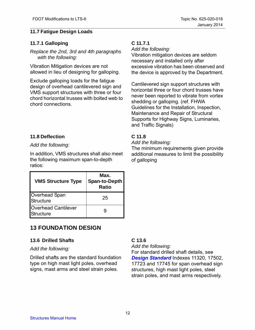
C 11.8Add the following:The minimum requirements given provide additional measures to limit the possibility of galloping
11.8 Deflection
Add the following:
In addition, VMS structures shall also meet the following maximum span-to-depth ratios:
VMS Structure TypeMax.
Span-to-DepthRatio
Overhead Span Structure
25
Overhead Cantilever Structure
9
13 FOUNDATION DESIGN
C 13.6 Add the following:For standard drilled shaft details, see Design Standard Indexes 11320, 17502, 17723 and 17745 for span overhead sign structures, high mast light poles, steel strain poles, and mast arms respectively.
13.6 Drilled Shafts
Add the following:
Drilled shafts are the standard foundation type on high mast light poles, overhead signs, mast arms and steel strain poles.
12Structures Manual Home

FDOT Modifications to LTS-6 Topic No. 625-020-018
January 2014
13.6.1 Geotechnical Design
C 13.6.1.1Add the following:FDOT experience has established a safety factor of 2 produces conservative designs.The torsion resistance equation is based on the theory for the Beta Method (O'Neill
and Reese, 1999). A single fdot factor of 1.5 is used to adjust for the concurrent overturning and torsional forces and to compare with past FDOT practice. Since the consequence of a torsion soil-structure failure is usually small, some rotation is typically allowable from the design wind.Since cantilever overhead sign structures can have significantly more torsion than a Mast Arm, a higher safety factor of 1.3 is appropriate.For soils with SPT N-values less than 5, consult the Geotechnical Engineer for additional recommendations.
13.6.1.1 Embedment (Rev. 01/14)
Add the following:
Use a safety factor against overturning of 2 when using the Broms method.For torsion resistance in drilled shafts supporting Mast Arm signal and cantilever overhead sign structures, use the following equations:
Tu
Tn
SFtor--------------
Where
Tn DLFsD2---- D
2---- 2
LconcD3---- +=
Fs vfdot=
v soilL2--- =
soil tan=
Tu = Torsion force on the drilled shaft
Tn = Nominal torsion resistance of the drilled shaft
SFtor = Safety Factor against torsion
= 1.0 for Mast Arm signal structures= 1.3 for overhead cantilever sign
structuresD = diameter of the drilled shaftL = length of the drilled shaftFs = unit skin friction
v = effective vertical stress at mid-layerfdot = load transfer ratio where the allowable shaft rotation may exceed 10 degrees
= 1.5 for granular soils where uncorrected SPT N-values are 15 or greater
= 1.5 N value–
15--------------------------- for uncorrected
N-values greater than or equal to 5 and less than 15.
13Structures Manual Home

FDOT Modifications to LTS-6 Topic No. 625-020-018
conc
January 2014
= unit weight of concretesoil = unit weight of soil
= Coefficient of friction between the shaft and soil
soil =soil friction angle
C 13.6.2Add the following:Using 1% steel is conservative for flexural design in most cases. Additional stirrups in the top of the shaft provides resistance against shear failure in the top of the shaft. Due to torsion, additional stirrups may be required in cantilever structures.
13.6.2 Structural Design
Add the following:
Longitudinally reinforce drilled shaft foundations with a minimum of 1% steel. At a minimum, place #5 stirrups at 4 inch spacing in the top two feet of shaft. In cantilever structures, design for shear resulting from the torsion loading on the anchor bolt group.
C 13.6.2.1Add the following:FDOT requires six inches of cover to ensure durability in drilled shafts.Concrete consolidation below the anchor bolts becomes more difficult with reinforcement clear spacing less than six inches.
13.6.2.1 Details
Replace the second sentence with the following:
A minimum concrete cover of six inches over steel reinforcement is required.
Add the following:
The minimum diameter for drilled shafts is 36 inches. A minimum main reinforcement clear spacing of six inches is required for proper concrete consolidation. Stirrups in drilled shafts for sign, signal and lighting structures are exempt from this spacing requirement.
13.10 Embedment of Lightly Loaded Small Poles and Posts
Add the following:
When using the Broms method for ground sign foundation design, use a safety factor against overturning of 1.3. When using the Broms method for direct burial concrete pole foundation design, use a safety factor against overturning of 1.5.
14Structures Manual Home

FDOT Modifications to LTS-6 Topic No. 625-020-018
January 2014
13.11 References
Add the following:
Cook, R.A. (2007). Anchor Embedment Requirements for Signal/Sign Structures (FDOT Report# BD545 RPWO #54). Gainesville, Florida: University of Florida.
APPENDIX C
C C.1Add the following:By allowing an overstress factor of 1.4, consistent with previous editions of LTS, properly designed existing structures will be allowed to remain in place in accordance with the PPM.
C.1 Alternate Method (Rev. 01/14)
Add the following:
When using Appendix C:• an allowable overstress factor (LTS 3.4)
of 1.4 for Group II loading is allowed.• FDOT minimum sign areas (FDOT
2.4.2.2) are not required.• fatigue evaluation (LTS Section 11) is
not required.• foundation evaluation (LTS Section 13),
structural and geotechnical, is not required.
In addition, if any of the following details exist, a Design Variation/Exception is not required:• mast arm connections with 4 bolt
(FDOT 5.17)• tapped mast arm connections (FDOT
5.16)• fillet welded tube-to-transverse plate
connections (FDOT 5.15.3)• 4 bolt mast arm anchorage
connections (FDOT 5.17)• transverse plate thickness (FDOT 5.14.3)
◦ mast arm horizontal and upright 1.5 inches and greater
◦ high mast light pole and steel strain pole 2.0 inches and greater
All items listed above should be checked in situations where there is evidence of distress or instability, or where the Engineer has reason to believe the structural capacity is in doubt.
15Structures Manual Home

FDOT Modifications to LTS-6 Topic No. 625-020-018
January 2014
C C.2Add the following:To simplify the design process, FDOT has designated one wind speed per county.
C.2 Wind Load
Delete the 2nd and 3rd sentence and add the following:
The design wind pressures shall be computed using the wind pressure formula, Eq. C-1, with the appropriate wind speed shown in FDOT Table C.2-1, Wind Speed by County.
16Structures Manual Home

FDOT Modifications to LTS-6 Topic No. 625-020-018
FDOT Table C.2-1 Wind Speed by County
County (Dist)10
year25
year50
yearCounty (Dist)
10year
25year
50year
Alachua (2) 60 80 90 Lee (1) 80 90 100
Baker (2) 60 80 90 Leon (3) 60 70 80
Bay (3) 70 80 90 Levy (2) 70 80 90
Bradford (2) 60 80 90 Liberty (3) 60 80 90
Brevard (5) 80 90 100 Madison (2) 60 70 80
Broward (4) 90 100 110 Manatee (1) 80 90 100
Calhoun (3) 60 80 90 Marion (5) 60 80 90
Charlotte (1) 80 90 100 Martin (4) 80 90 100
Citrus (7) 70 80 90 Miami-Dade (6) 90 100 110
Clay (2) 60 80 90 Monroe (6) 90 100 110
Collier (1) 80 90 100 Nassau (2) 70 80 90
Columbia (2) 60 70 80 Okaloosa (3) 70 90 100
DeSoto (1) 70 80 90 Okeechobee (1) 70 80 90
Dixie (2) 70 80 90 Orange (5) 70 80 90
Duval (2) 70 80 90 Osceola (5) 70 80 90
Escambia (3) 70 90 100 Palm Beach (4) 80 100 110
Flagler (5) 70 80 90 Pasco (7) 70 90 100
Franklin (3) 70 90 100 Pinellas (7) 70 90 100
Gadsden (3) 60 70 80 Polk (1) 70 80 90
Gilchrist (2) 60 80 90 Putnam (2) 60 80 90
Glades (1) 70 80 90 St. Johns (2) 70 80 90
Gulf (3) 70 90 100 St. Lucie (4) 80 90 100
Hamilton (2) 60 70 80 Santa Rosa (3) 70 90 100
Hardee (1) 70 80 90 Sarasota (1) 80 90 100
Hendry (1) 70 80 90 Seminole (5) 70 80 90
Hernando (7) 70 90 100 Sumter (5) 60 80 90
Highlands (1) 70 80 90 Suwannee (2) 60 70 80
Hillsborough (7) 70 80 90 Taylor (2) 70 80 90
Holmes (3) 60 70 80 Union (2) 60 80 90
Indian River (4) 80 90 100 Volusia (5) 80 90 100
Jackson (3) 60 70 80 Wakulla (3) 70 80 90
Jefferson (3) 60 70 80 Walton (3) 70 80 90
Lafayette (2) 60 80 90 Washington (3) 60 80 90
Lake (5) 60 80 90
January 2014
17Structures Manual Home

FDOT Modifications to LTS-6 Topic No. 625-020-018
Volume 3 - Revision History January 2014
R3-1Structures Manual Home
VOLUME 3 - REVISION HISTORY
2.4.2.2 ..........Revised first Paragraph and Figure 2.
2.4.2.5 ..........Revised maximum length of Span Overhead Sign Structures from 250 to 220 feet.
3.8 ................Clarified Commentary.
5.14.3 ...........Added criteria for mast arm signal structures, steel strain poles and high mast light poles.
5.17.2.4 ........Added new Section and associated Commentary.
5.17.3.1 ........Added new Section and Commentary.
5.17.3.3 ........Revised criteria and associated Commentary regarding the use of grout pads.
5.17.4.3 ........Replaced Section and associated Commentary.
5.19 ..............Added new Section
11.6 ..............Added galloping requirement; Changed cross references; Deleted some Commentary.
13.6.1.1 ........Added "uncorrected" to definition of ωfdot.
C.1 ...............Revised Section.